WO2020095940A1 - 溶融めっき方法 - Google Patents
溶融めっき方法 Download PDFInfo
- Publication number
- WO2020095940A1 WO2020095940A1 PCT/JP2019/043455 JP2019043455W WO2020095940A1 WO 2020095940 A1 WO2020095940 A1 WO 2020095940A1 JP 2019043455 W JP2019043455 W JP 2019043455W WO 2020095940 A1 WO2020095940 A1 WO 2020095940A1
- Authority
- WO
- WIPO (PCT)
- Prior art keywords
- hot
- plating
- bath
- dip
- vibration
- Prior art date
- Legal status (The legal status is an assumption and is not a legal conclusion. Google has not performed a legal analysis and makes no representation as to the accuracy of the status listed.)
- Ceased
Links
Images








Classifications
-
- C—CHEMISTRY; METALLURGY
- C23—COATING METALLIC MATERIAL; COATING MATERIAL WITH METALLIC MATERIAL; CHEMICAL SURFACE TREATMENT; DIFFUSION TREATMENT OF METALLIC MATERIAL; COATING BY VACUUM EVAPORATION, BY SPUTTERING, BY ION IMPLANTATION OR BY CHEMICAL VAPOUR DEPOSITION, IN GENERAL; INHIBITING CORROSION OF METALLIC MATERIAL OR INCRUSTATION IN GENERAL
- C23C—COATING METALLIC MATERIAL; COATING MATERIAL WITH METALLIC MATERIAL; SURFACE TREATMENT OF METALLIC MATERIAL BY DIFFUSION INTO THE SURFACE, BY CHEMICAL CONVERSION OR SUBSTITUTION; COATING BY VACUUM EVAPORATION, BY SPUTTERING, BY ION IMPLANTATION OR BY CHEMICAL VAPOUR DEPOSITION, IN GENERAL
- C23C2/00—Hot-dipping or immersion processes for applying the coating material in the molten state without affecting the shape; Apparatus therefor
- C23C2/04—Hot-dipping or immersion processes for applying the coating material in the molten state without affecting the shape; Apparatus therefor characterised by the coating material
- C23C2/06—Zinc or cadmium or alloys based thereon
-
- C—CHEMISTRY; METALLURGY
- C23—COATING METALLIC MATERIAL; COATING MATERIAL WITH METALLIC MATERIAL; CHEMICAL SURFACE TREATMENT; DIFFUSION TREATMENT OF METALLIC MATERIAL; COATING BY VACUUM EVAPORATION, BY SPUTTERING, BY ION IMPLANTATION OR BY CHEMICAL VAPOUR DEPOSITION, IN GENERAL; INHIBITING CORROSION OF METALLIC MATERIAL OR INCRUSTATION IN GENERAL
- C23C—COATING METALLIC MATERIAL; COATING MATERIAL WITH METALLIC MATERIAL; SURFACE TREATMENT OF METALLIC MATERIAL BY DIFFUSION INTO THE SURFACE, BY CHEMICAL CONVERSION OR SUBSTITUTION; COATING BY VACUUM EVAPORATION, BY SPUTTERING, BY ION IMPLANTATION OR BY CHEMICAL VAPOUR DEPOSITION, IN GENERAL
- C23C2/00—Hot-dipping or immersion processes for applying the coating material in the molten state without affecting the shape; Apparatus therefor
- C23C2/32—Hot-dipping or immersion processes for applying the coating material in the molten state without affecting the shape; Apparatus therefor using vibratory energy applied to the bath or substrate
-
- C—CHEMISTRY; METALLURGY
- C23—COATING METALLIC MATERIAL; COATING MATERIAL WITH METALLIC MATERIAL; CHEMICAL SURFACE TREATMENT; DIFFUSION TREATMENT OF METALLIC MATERIAL; COATING BY VACUUM EVAPORATION, BY SPUTTERING, BY ION IMPLANTATION OR BY CHEMICAL VAPOUR DEPOSITION, IN GENERAL; INHIBITING CORROSION OF METALLIC MATERIAL OR INCRUSTATION IN GENERAL
- C23C—COATING METALLIC MATERIAL; COATING MATERIAL WITH METALLIC MATERIAL; SURFACE TREATMENT OF METALLIC MATERIAL BY DIFFUSION INTO THE SURFACE, BY CHEMICAL CONVERSION OR SUBSTITUTION; COATING BY VACUUM EVAPORATION, BY SPUTTERING, BY ION IMPLANTATION OR BY CHEMICAL VAPOUR DEPOSITION, IN GENERAL
- C23C2/00—Hot-dipping or immersion processes for applying the coating material in the molten state without affecting the shape; Apparatus therefor
- C23C2/003—Apparatus
- C23C2/0032—Apparatus specially adapted for batch coating of substrate
- C23C2/00322—Details of mechanisms for immersing or removing substrate from molten liquid bath, e.g. basket or lifting mechanism
-
- C—CHEMISTRY; METALLURGY
- C23—COATING METALLIC MATERIAL; COATING MATERIAL WITH METALLIC MATERIAL; CHEMICAL SURFACE TREATMENT; DIFFUSION TREATMENT OF METALLIC MATERIAL; COATING BY VACUUM EVAPORATION, BY SPUTTERING, BY ION IMPLANTATION OR BY CHEMICAL VAPOUR DEPOSITION, IN GENERAL; INHIBITING CORROSION OF METALLIC MATERIAL OR INCRUSTATION IN GENERAL
- C23C—COATING METALLIC MATERIAL; COATING MATERIAL WITH METALLIC MATERIAL; SURFACE TREATMENT OF METALLIC MATERIAL BY DIFFUSION INTO THE SURFACE, BY CHEMICAL CONVERSION OR SUBSTITUTION; COATING BY VACUUM EVAPORATION, BY SPUTTERING, BY ION IMPLANTATION OR BY CHEMICAL VAPOUR DEPOSITION, IN GENERAL
- C23C2/00—Hot-dipping or immersion processes for applying the coating material in the molten state without affecting the shape; Apparatus therefor
- C23C2/003—Apparatus
- C23C2/0034—Details related to elements immersed in bath
- C23C2/00342—Moving elements, e.g. pumps or mixers
-
- C—CHEMISTRY; METALLURGY
- C23—COATING METALLIC MATERIAL; COATING MATERIAL WITH METALLIC MATERIAL; CHEMICAL SURFACE TREATMENT; DIFFUSION TREATMENT OF METALLIC MATERIAL; COATING BY VACUUM EVAPORATION, BY SPUTTERING, BY ION IMPLANTATION OR BY CHEMICAL VAPOUR DEPOSITION, IN GENERAL; INHIBITING CORROSION OF METALLIC MATERIAL OR INCRUSTATION IN GENERAL
- C23C—COATING METALLIC MATERIAL; COATING MATERIAL WITH METALLIC MATERIAL; SURFACE TREATMENT OF METALLIC MATERIAL BY DIFFUSION INTO THE SURFACE, BY CHEMICAL CONVERSION OR SUBSTITUTION; COATING BY VACUUM EVAPORATION, BY SPUTTERING, BY ION IMPLANTATION OR BY CHEMICAL VAPOUR DEPOSITION, IN GENERAL
- C23C2/00—Hot-dipping or immersion processes for applying the coating material in the molten state without affecting the shape; Apparatus therefor
- C23C2/003—Apparatus
- C23C2/0038—Apparatus characterised by the pre-treatment chambers located immediately upstream of the bath or occurring locally before the dipping process
- C23C2/004—Snouts
-
- C—CHEMISTRY; METALLURGY
- C23—COATING METALLIC MATERIAL; COATING MATERIAL WITH METALLIC MATERIAL; CHEMICAL SURFACE TREATMENT; DIFFUSION TREATMENT OF METALLIC MATERIAL; COATING BY VACUUM EVAPORATION, BY SPUTTERING, BY ION IMPLANTATION OR BY CHEMICAL VAPOUR DEPOSITION, IN GENERAL; INHIBITING CORROSION OF METALLIC MATERIAL OR INCRUSTATION IN GENERAL
- C23C—COATING METALLIC MATERIAL; COATING MATERIAL WITH METALLIC MATERIAL; SURFACE TREATMENT OF METALLIC MATERIAL BY DIFFUSION INTO THE SURFACE, BY CHEMICAL CONVERSION OR SUBSTITUTION; COATING BY VACUUM EVAPORATION, BY SPUTTERING, BY ION IMPLANTATION OR BY CHEMICAL VAPOUR DEPOSITION, IN GENERAL
- C23C2/00—Hot-dipping or immersion processes for applying the coating material in the molten state without affecting the shape; Apparatus therefor
- C23C2/02—Pretreatment of the material to be coated, e.g. for coating on selected surface areas
- C23C2/022—Pretreatment of the material to be coated, e.g. for coating on selected surface areas by heating
- C23C2/0222—Pretreatment of the material to be coated, e.g. for coating on selected surface areas by heating in a reactive atmosphere, e.g. oxidising or reducing atmosphere
-
- C—CHEMISTRY; METALLURGY
- C23—COATING METALLIC MATERIAL; COATING MATERIAL WITH METALLIC MATERIAL; CHEMICAL SURFACE TREATMENT; DIFFUSION TREATMENT OF METALLIC MATERIAL; COATING BY VACUUM EVAPORATION, BY SPUTTERING, BY ION IMPLANTATION OR BY CHEMICAL VAPOUR DEPOSITION, IN GENERAL; INHIBITING CORROSION OF METALLIC MATERIAL OR INCRUSTATION IN GENERAL
- C23C—COATING METALLIC MATERIAL; COATING MATERIAL WITH METALLIC MATERIAL; SURFACE TREATMENT OF METALLIC MATERIAL BY DIFFUSION INTO THE SURFACE, BY CHEMICAL CONVERSION OR SUBSTITUTION; COATING BY VACUUM EVAPORATION, BY SPUTTERING, BY ION IMPLANTATION OR BY CHEMICAL VAPOUR DEPOSITION, IN GENERAL
- C23C2/00—Hot-dipping or immersion processes for applying the coating material in the molten state without affecting the shape; Apparatus therefor
- C23C2/02—Pretreatment of the material to be coated, e.g. for coating on selected surface areas
- C23C2/024—Pretreatment of the material to be coated, e.g. for coating on selected surface areas by cleaning or etching
-
- C—CHEMISTRY; METALLURGY
- C23—COATING METALLIC MATERIAL; COATING MATERIAL WITH METALLIC MATERIAL; CHEMICAL SURFACE TREATMENT; DIFFUSION TREATMENT OF METALLIC MATERIAL; COATING BY VACUUM EVAPORATION, BY SPUTTERING, BY ION IMPLANTATION OR BY CHEMICAL VAPOUR DEPOSITION, IN GENERAL; INHIBITING CORROSION OF METALLIC MATERIAL OR INCRUSTATION IN GENERAL
- C23C—COATING METALLIC MATERIAL; COATING MATERIAL WITH METALLIC MATERIAL; SURFACE TREATMENT OF METALLIC MATERIAL BY DIFFUSION INTO THE SURFACE, BY CHEMICAL CONVERSION OR SUBSTITUTION; COATING BY VACUUM EVAPORATION, BY SPUTTERING, BY ION IMPLANTATION OR BY CHEMICAL VAPOUR DEPOSITION, IN GENERAL
- C23C2/00—Hot-dipping or immersion processes for applying the coating material in the molten state without affecting the shape; Apparatus therefor
- C23C2/04—Hot-dipping or immersion processes for applying the coating material in the molten state without affecting the shape; Apparatus therefor characterised by the coating material
- C23C2/08—Tin or alloys based thereon
-
- C—CHEMISTRY; METALLURGY
- C23—COATING METALLIC MATERIAL; COATING MATERIAL WITH METALLIC MATERIAL; CHEMICAL SURFACE TREATMENT; DIFFUSION TREATMENT OF METALLIC MATERIAL; COATING BY VACUUM EVAPORATION, BY SPUTTERING, BY ION IMPLANTATION OR BY CHEMICAL VAPOUR DEPOSITION, IN GENERAL; INHIBITING CORROSION OF METALLIC MATERIAL OR INCRUSTATION IN GENERAL
- C23C—COATING METALLIC MATERIAL; COATING MATERIAL WITH METALLIC MATERIAL; SURFACE TREATMENT OF METALLIC MATERIAL BY DIFFUSION INTO THE SURFACE, BY CHEMICAL CONVERSION OR SUBSTITUTION; COATING BY VACUUM EVAPORATION, BY SPUTTERING, BY ION IMPLANTATION OR BY CHEMICAL VAPOUR DEPOSITION, IN GENERAL
- C23C2/00—Hot-dipping or immersion processes for applying the coating material in the molten state without affecting the shape; Apparatus therefor
- C23C2/04—Hot-dipping or immersion processes for applying the coating material in the molten state without affecting the shape; Apparatus therefor characterised by the coating material
- C23C2/12—Aluminium or alloys based thereon
-
- C—CHEMISTRY; METALLURGY
- C23—COATING METALLIC MATERIAL; COATING MATERIAL WITH METALLIC MATERIAL; CHEMICAL SURFACE TREATMENT; DIFFUSION TREATMENT OF METALLIC MATERIAL; COATING BY VACUUM EVAPORATION, BY SPUTTERING, BY ION IMPLANTATION OR BY CHEMICAL VAPOUR DEPOSITION, IN GENERAL; INHIBITING CORROSION OF METALLIC MATERIAL OR INCRUSTATION IN GENERAL
- C23C—COATING METALLIC MATERIAL; COATING MATERIAL WITH METALLIC MATERIAL; SURFACE TREATMENT OF METALLIC MATERIAL BY DIFFUSION INTO THE SURFACE, BY CHEMICAL CONVERSION OR SUBSTITUTION; COATING BY VACUUM EVAPORATION, BY SPUTTERING, BY ION IMPLANTATION OR BY CHEMICAL VAPOUR DEPOSITION, IN GENERAL
- C23C2/00—Hot-dipping or immersion processes for applying the coating material in the molten state without affecting the shape; Apparatus therefor
- C23C2/50—Controlling or regulating the coating processes
- C23C2/51—Computer-controlled implementation
-
- C—CHEMISTRY; METALLURGY
- C23—COATING METALLIC MATERIAL; COATING MATERIAL WITH METALLIC MATERIAL; CHEMICAL SURFACE TREATMENT; DIFFUSION TREATMENT OF METALLIC MATERIAL; COATING BY VACUUM EVAPORATION, BY SPUTTERING, BY ION IMPLANTATION OR BY CHEMICAL VAPOUR DEPOSITION, IN GENERAL; INHIBITING CORROSION OF METALLIC MATERIAL OR INCRUSTATION IN GENERAL
- C23C—COATING METALLIC MATERIAL; COATING MATERIAL WITH METALLIC MATERIAL; SURFACE TREATMENT OF METALLIC MATERIAL BY DIFFUSION INTO THE SURFACE, BY CHEMICAL CONVERSION OR SUBSTITUTION; COATING BY VACUUM EVAPORATION, BY SPUTTERING, BY ION IMPLANTATION OR BY CHEMICAL VAPOUR DEPOSITION, IN GENERAL
- C23C2/00—Hot-dipping or immersion processes for applying the coating material in the molten state without affecting the shape; Apparatus therefor
- C23C2/50—Controlling or regulating the coating processes
- C23C2/52—Controlling or regulating the coating processes with means for measuring or sensing
-
- C—CHEMISTRY; METALLURGY
- C23—COATING METALLIC MATERIAL; COATING MATERIAL WITH METALLIC MATERIAL; CHEMICAL SURFACE TREATMENT; DIFFUSION TREATMENT OF METALLIC MATERIAL; COATING BY VACUUM EVAPORATION, BY SPUTTERING, BY ION IMPLANTATION OR BY CHEMICAL VAPOUR DEPOSITION, IN GENERAL; INHIBITING CORROSION OF METALLIC MATERIAL OR INCRUSTATION IN GENERAL
- C23C—COATING METALLIC MATERIAL; COATING MATERIAL WITH METALLIC MATERIAL; SURFACE TREATMENT OF METALLIC MATERIAL BY DIFFUSION INTO THE SURFACE, BY CHEMICAL CONVERSION OR SUBSTITUTION; COATING BY VACUUM EVAPORATION, BY SPUTTERING, BY ION IMPLANTATION OR BY CHEMICAL VAPOUR DEPOSITION, IN GENERAL
- C23C28/00—Coating for obtaining at least two superposed coatings either by methods not provided for in a single one of groups C23C2/00 - C23C26/00 or by combinations of methods provided for in subclasses C23C and C25C or C25D
-
- C—CHEMISTRY; METALLURGY
- C23—COATING METALLIC MATERIAL; COATING MATERIAL WITH METALLIC MATERIAL; CHEMICAL SURFACE TREATMENT; DIFFUSION TREATMENT OF METALLIC MATERIAL; COATING BY VACUUM EVAPORATION, BY SPUTTERING, BY ION IMPLANTATION OR BY CHEMICAL VAPOUR DEPOSITION, IN GENERAL; INHIBITING CORROSION OF METALLIC MATERIAL OR INCRUSTATION IN GENERAL
- C23C—COATING METALLIC MATERIAL; COATING MATERIAL WITH METALLIC MATERIAL; SURFACE TREATMENT OF METALLIC MATERIAL BY DIFFUSION INTO THE SURFACE, BY CHEMICAL CONVERSION OR SUBSTITUTION; COATING BY VACUUM EVAPORATION, BY SPUTTERING, BY ION IMPLANTATION OR BY CHEMICAL VAPOUR DEPOSITION, IN GENERAL
- C23C28/00—Coating for obtaining at least two superposed coatings either by methods not provided for in a single one of groups C23C2/00 - C23C26/00 or by combinations of methods provided for in subclasses C23C and C25C or C25D
- C23C28/30—Coatings combining at least one metallic layer and at least one inorganic non-metallic layer
- C23C28/32—Coatings combining at least one metallic layer and at least one inorganic non-metallic layer including at least one pure metallic layer
- C23C28/322—Coatings combining at least one metallic layer and at least one inorganic non-metallic layer including at least one pure metallic layer only coatings of metal elements only
-
- C—CHEMISTRY; METALLURGY
- C23—COATING METALLIC MATERIAL; COATING MATERIAL WITH METALLIC MATERIAL; CHEMICAL SURFACE TREATMENT; DIFFUSION TREATMENT OF METALLIC MATERIAL; COATING BY VACUUM EVAPORATION, BY SPUTTERING, BY ION IMPLANTATION OR BY CHEMICAL VAPOUR DEPOSITION, IN GENERAL; INHIBITING CORROSION OF METALLIC MATERIAL OR INCRUSTATION IN GENERAL
- C23C—COATING METALLIC MATERIAL; COATING MATERIAL WITH METALLIC MATERIAL; SURFACE TREATMENT OF METALLIC MATERIAL BY DIFFUSION INTO THE SURFACE, BY CHEMICAL CONVERSION OR SUBSTITUTION; COATING BY VACUUM EVAPORATION, BY SPUTTERING, BY ION IMPLANTATION OR BY CHEMICAL VAPOUR DEPOSITION, IN GENERAL
- C23C28/00—Coating for obtaining at least two superposed coatings either by methods not provided for in a single one of groups C23C2/00 - C23C26/00 or by combinations of methods provided for in subclasses C23C and C25C or C25D
- C23C28/30—Coatings combining at least one metallic layer and at least one inorganic non-metallic layer
- C23C28/32—Coatings combining at least one metallic layer and at least one inorganic non-metallic layer including at least one pure metallic layer
- C23C28/322—Coatings combining at least one metallic layer and at least one inorganic non-metallic layer including at least one pure metallic layer only coatings of metal elements only
- C23C28/3225—Coatings combining at least one metallic layer and at least one inorganic non-metallic layer including at least one pure metallic layer only coatings of metal elements only with at least one zinc-based layer
Definitions
- the present invention relates to a hot-dip plating method for metal materials, and more particularly to a hot-dip plating method for steel materials.
- hot-dip plating methods are roughly classified into continuous hot-dip plating methods and immersion plating methods.
- a steel material will be exemplified as a representative of metal materials, and a hot-dip plating method for steel material will be described.
- the continuous hot-dip plating method is a method in which a coil-shaped steel material (metal strip) is continuously passed (immersed and passed) through a hot-dip plating bath to plate the steel material.
- the immersion plating method is a so-called “dough pickling plating", which is a method of depositing a flux on a preformed steel material and then immersing the steel material in a hot dip bath to perform plating. ..
- the equipment (continuous hot-dip plating equipment) used for carrying out the continuous hot-dip plating method usually includes a pretreatment equipment, a reduction heating furnace, a hot-dip galvanizing bath (molten metal pot), and a post-treatment equipment.
- a pretreatment facility a treatment for removing rolling oil and dirt adhering to the steel material is performed.
- the reduction heating furnace the steel material is heated in an atmosphere containing H 2 to reduce the Fe oxide existing on the surface of the steel material.
- the hot dip bath part the steel material treated in the reduction heating furnace is immersed in and passed through the hot dip bath while being held in a reducing atmosphere or in an atmosphere that prevents reoxidation of the steel surface, thereby Is subjected to hot dip coating.
- various treatments are performed on the hot-dipped steel material depending on the application.
- the equipment used to carry out Dobu-zuke plating is a degreasing equipment that removes oil and dirt from preformed steel materials, and an Fe oxide layer (called rust or black skin).
- a flux equipment for applying a flux to the pickled steel material, and a hot dip bath section for performing hot dip plating on the steel material after drying the flux is a degreasing equipment that removes oil and dirt from preformed steel materials, and an Fe oxide layer (called rust or black skin).
- a flux equipment for applying a flux to the pickled steel material, and a hot dip bath section for performing hot dip plating on the steel material after drying the flux is a post-treatment equipment may be attached to the dobu-zuke plating equipment as in the case of the continuous hot dip plating equipment.
- the flux is used to improve the reactivity between the steel material and the hot dip bath.
- the problem of occurrence of plating defects (called non-plating or pinholes) on the surface of a plated product (semi-finished product) after hot-dip plating may occur.
- the plating defect is a portion in which the molten metal does not adhere to the steel material and the plated metal does not exist on the surface of the steel material.
- countermeasures have been taken for many years.
- a technique of performing hot-dip plating in a state where ultrasonic vibration is applied to a metal strip after heat treatment (reduction treatment) in a continuous hot-dip plating method Patent Documents 1 and 2). See).
- a technique has been proposed for performing Dobuzuke plating using ultrasonic waves to solve the problem of non-plating caused by burns (exposed alloy layer) (Patent Document 3). See).
- the annealing treatment of the material of the metal strip and the reduction treatment of the oxide film existing on the surface of the metal strip are performed by the reduction heating furnace in the previous step of immersing the metal strip in the molten metal pot. ..
- the metal band is heat-treated in a mixed atmosphere of, for example, nitrogen and hydrogen in order to reduce the oxide film.
- the heating temperature of the metal strip is set according to the intended use of the plated product, and in order to improve the reactivity between the metal strip and the hot dip bath, the metal strip must be at least at the temperature of the hot dip bath or higher. Be heated.
- the oxide film on the surface of the metal strip is removed by the treatment in the reduction heating furnace, the reactivity between the metal strip and the hot dip bath is improved in the hot dip bath. Therefore, it is possible to stably produce the hot-dipped metal strip.
- JP-A-2-125850 Japanese Unexamined Patent Publication “JP-A-2-28456” Japanese Patent Laid-Open Publication "JP 2000-064020”
- plating defects may occur on the surface of plated products.This is not only the case of continuous hot dip plating but also of dobuzuke plating. The same applies when a plated product is manufactured.
- the reduction heating furnace in continuous hot dip coating equipment requires a very large amount of heat and consumes a large amount of nitrogen and hydrogen used as atmospheric gases. This also applies to the techniques described in Patent Documents 1 and 2. In the conventional continuous hot dip plating method, it is not easy to reduce the energy consumption while satisfying the requirements for hot dip plated products (small plating defects, etc.).
- the dobu-zuke plating facility is usually provided with a flux facility to ensure good plating properties.
- a flux facility to ensure good plating properties.
- chloride including ZnCl 2 , NH 4 Cl, etc.
- One aspect of the present invention has been made in view of the above-mentioned conventional problems, and an object thereof is that the plating adhesion on the surface of the metal material after performing hot dip plating is good, and the energy is higher than in the past.
- An object of the present invention is to provide a hot-dip plating method capable of reducing the consumption amount and improving the working environment.
- a hot-dip plating method is a hot-dip plating method in which a metal material is introduced into a plating bath that is a hot metal to coat the hot metal with the hot metal.
- a plating step of coating the molten metal on the metal material while applying vibration to the plating bath wherein the frequency of the vibration applied to the plating bath is a basic frequency, and the plating step includes: The above-mentioned vibration is applied so that the acoustic spectrum measured in the bath satisfies the relationship of the following formula (1).
- IB-NB Average value of sound pressure over the entire measurement frequency band
- IB (i) Between sound pressure peak at the fundamental frequency and sound pressure peak at the second overtone frequency, and (ii) sound pressure at a plurality of overtone frequencies Of the sound pressure in a specific frequency band between adjacent peaks of the peaks of NA: NA: the average value of the sound pressure of the entire measurement frequency band when the vibration is not applied
- NB Specified with respect to the IB It is an average value of sound pressure in the specific frequency band when the vibration is not applied).
- the intensity ratio obtained by (IB-NB) / (IA-NA) as described above may be referred to as a characteristic intensity ratio.
- the present inventors perform hot dip plating on a metal material in which the thickness of the oxide film formed on the surface is reduced by pretreatment, under the condition that the characteristic strength ratio is larger than 0.2. It has been found that this improves the plating adhesion of the metal material.
- the hot-dip plating that has good plating adhesion on the surface of the metal material after hot-dip plating can reduce energy consumption and improve the working environment more than before.
- a method can be provided.
- FIG. 1 is a schematic diagram showing a state in which a steel sheet is introduced into a hot dip bath under an air atmosphere
- (b) is an enlarged schematic diagram showing a region (A1) in the diagram shown in (a).
- FIG. It is an acoustic spectrum observed when a hot dip bath is vibrated by using an ultrasonic oscillator with an output of 380 W.
- (A) is a schematic diagram showing a state in which hot-dip plating is performed on a steel sheet having a relatively thick oxide film in the comparative example, and (b) is a pretreatment for reducing the thickness of the oxide film in the example of the present invention.
- It is a schematic diagram which shows a mode that hot-dip plating is performed about the processed steel plate. It is a graph which shows the relationship between the analytical depth from the surface in the steel plate before hot dip coating, and the intensity
- hot dip bath metal various kinds of molten metal (molten metal) forming the hot dip bath
- the material and shape of the steel material to be subjected to hot dip plating using the hot dip bath are not particularly limited unless otherwise specified.
- steel plate may be read as “steel band” as long as there is no inconvenience.
- platability means both the wettability of the metal material and the hot-dip plating bath, and the adhesion between the metal material and the plating layer formed on the surface of the metal material. Is sometimes referred to as platability.
- platability in the present specification, “plating property”, “plating wettability”, and “plating adhesion” are used in the same meaning as in the past.
- FIG. 13A is a schematic diagram showing a state in which a steel sheet is allowed to enter a hot dip bath under an air atmosphere.
- FIG. 13B is a partially enlarged view schematically showing a region (A1) shown in FIG. 13A in an enlarged manner.
- the steel plate 100 that has not been subjected to the reduction treatment is allowed to enter the hot dip bath 110 in the atmosphere.
- An oxide film (oxide film) is formed on the surface of the steel plate 100.
- a bath surface oxide 112 exists at the boundary (that is, the surface of the hot dip coating bath 110) between the hot dip bath metal 111 inside the hot dip bath 110 and the atmosphere (atmosphere) outside the hot dip bath 110. To do.
- the steel sheet 100 includes (i) the bath surface oxide 112 and (ii) the air entrainment layer 120 formed by the atmospheric gas (air) on the surface of the hot dip bath 110. As it is rolled in, it enters the hot-dip plating bath 110. As a result, inside the hot dip bath 110, the reaction inhibiting portion 130 is formed between the hot dip bath metal 111 and the oxide film 101 of the steel plate 100. The reaction inhibiting portion 130 is formed by the bath surface oxide 112 and the air entrainment layer 120 in a composite manner.
- the reaction between the steel sheet 100 and the hot dip bath metal 111 is hindered by the oxide film 101 and the reaction inhibiting portion 130, so that the surface of the plated product after being pulled up from the hot dip bath 110 has no plating defect (pinhole or non-plating). Etc.) easily occur.
- the steel sheet obtained by reducing the oxide film on the steel sheet surface using the heating furnace is introduced into the hot-dip plating bath through the snout held in the reducing atmosphere ( See, for example, Patent Documents 1 and 2.
- Patent Documents 1 and 2 See, for example, Patent Documents 1 and 2.
- the reaction between the steel sheet and the hot dip bath metal rapidly progresses.
- the present inventors have diligently studied a hot-dip plating method that can reduce energy consumption by a new method different from the above-mentioned conventional technology.
- the vibration activation effect produced by applying vibration under the specific conditions to the hot dip coating bath can enhance the reactivity between the steel material and the hot dip coating metal.
- the wettability of the steel material for plating can be enhanced.
- Such a phenomenon is a phenomenon that was not expected at all in the prior art, as can be seen from the structure in which the reduction heating furnace was arranged in the previous stage of the hot dip coating section in the conventional hot dipping equipment.
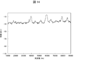
- FIG. 14 is an acoustic spectrum observed when vibration is applied to the hot-dip plating bath using an ultrasonic oscillator with an output of 380 W.
- the cavitation effect of high power ultrasonic irradiation to the hot dip bath is used to physically remove the oxide film existing on the steel plate surface (or the oxide film remaining on the steel plate surface after the reduction treatment). By breaking, the plateability of the steel sheet was improved.
- the inventors of the present invention have found that the vibration activating effect of the present invention is recognized even when a low-power ultrasonic transducer is used, and the plating wettability of the steel sheet is effectively improved. Found. In this case, a peak characteristic of the acoustic spectrum is observed, which will be specifically described later.
- the present inventors consider the following vibration activation effect, which is different from the conventional technique and which is exhibited even at a low sound pressure, as follows.
- the hot dip of the hot-dip galvanized metal vibrates due to sound waves, and this pressure vibration causes Bubbles are generated. It is considered that a shock wave is generated toward the periphery of the bubble when the generated bubble is crushed due to the pressure vibration. Further, it is considered that the bubbles repeatedly expand and contract due to the pressure vibration, and this expansion and contraction may cause a local flow of the hot-dip metal around the bubbles. Due to the action of the shock wave and the local flow based on the acoustic energy, the mass transfer is promoted at the interface between the steel material and the plating bath, and the effect of reducing the thickness of the boundary layer or increasing the mass transfer speed is brought about. As a result, a mechanism is considered in which the plating wettability between the steel material and the hot dip bath is secured.
- the reaction in which the steel material is dissolved in the hot dip plating bath is that the concentration of the components of the steel material such as iron (Fe) in the hot dip plating bath is increased, and as a result, the occurrence of dross is likely to occur.
- concentration of the components of the steel material such as iron (Fe) in the hot dip plating bath is increased, and as a result, the occurrence of dross is likely to occur.
- erosion of members (ultrasonic horns) and the like that are immersed in the bath for imparting vibration with high sound pressure to the hot dip bath is likely to occur, which makes maintenance of these members complicated.
- a hot-dip plating method (hereinafter sometimes simply referred to as the hot-dip plating method) according to an embodiment of the present invention based on the findings found by the present inventors. That is, (i) ultrasonic vibration is applied to the steel material, or (ii) ultrasonic vibration is applied to the hot-dip galvanizing bath using, for example, a vibration plate, so that vibration with a low sound pressure is applied to the hot-dip galvanizing bath. Give. Then, the acoustic spectrum is measured using an acoustic measuring device immersed in the hot dip bath.
- the ultrasonic vibration is applied to the hot dip bath so that the acoustic spectrum satisfies a predetermined condition.
- the ultrasonic vibration applied to the steel material or the diaphragm causes a vibration activation effect in the hot dip plating bath.
- the above-mentioned predetermined condition is defined to indirectly specify the degree of the vibration activation effect by using the acoustic spectrum in the hot dip bath so that the vibration activation effect above a certain level is generated.
- the inventors of the present invention have obtained the following findings as a result of further studies. That is, for example, ultrasonic vibration is applied to the hot-dip galvanizing bath so as to satisfy a predetermined condition for a steel material having a reduced oxide film thickness by performing a pretreatment such as pickling. While performing hot dip plating. It has been found that this makes it possible to improve the plating adhesion on the surface of the steel material after hot dipping.
- FIG. 15A is a schematic diagram showing how a steel sheet having a relatively thick oxide film is subjected to hot dip plating in a comparative example.
- FIG. 15 (b) is a schematic diagram showing a state in which hot-dip plating is performed on a steel sheet that has been subjected to pretreatment to reduce the thickness of the oxide film in the example of the present invention.
- FIG. 15 (a) in the case of performing hot dip plating while applying ultrasonic vibration to a steel plate 100 of a comparative example in which a relatively thick oxide film 101 is formed in a hot dip bath.
- the vibration activation effect occurs in the hot dip bath by ultrasonic vibration. That is, the molten plating metal in a molten state vibrates under pressure due to sound waves, and bubbles are generated in the plating bath due to this pressure vibration. It is considered that a shock wave is generated toward the periphery of the bubble when the generated bubble is crushed due to the pressure vibration. Further, it is considered that the bubbles repeatedly expand and contract due to the pressure vibration, and this expansion and contraction may cause a local flow of the hot-dip metal around the bubbles.
- the mass transfer is promoted at the interface between the steel material and the plating bath, and the thickness of the boundary layer is reduced, or the mass transfer rate is increased. Conceivable.
- the oxide film 101 when the oxide film 101 is relatively thick, the oxide film 101 remains on the surface of the steel sheet 100 and the plating layer 150 is formed on the oxide film 101 even if the mass transfer is promoted. It will be. As a result, it is considered that the plating layer 150 is easily separated from the surface of the oxide film 101 or the steel plate 100.
- the steel sheet 2 of the example of the present invention on which the thin oxide film 6 is formed is subjected to hot dipping while applying ultrasonic vibration in the hot dipping bath.
- the following reactions are considered to occur. That is, energy is applied to the oxide film 6 from the vibration activation region 23 generated in the molten plating bath metal 21.
- a reaction layer 7 is formed on the surface of the steel sheet 2 after the hot dip coating as a result of mutual atomic diffusion among the oxide film 6, the steel sheet 2, and the hot dip bath metal 21.
- the reaction layer 7 is an alloy layer containing the components of the steel plate 2 and the hot dip bath metal 21. Due to the reaction layer 7, the steel plate 2 and the plating layer 8 are relatively firmly bonded to each other. As a result, it is considered that the plating adhesion on the surface of the steel sheet 2 after hot dipping is improved.
- the phenomenon of improving the plating adhesion described above suitably occurs when hot dip plating is performed using a Zn-based hot dip plating bath.
- a hot dip plating bath containing 40 mass% or more of Zn it is possible to improve the plating adhesion on the surface of the steel sheet 2 after hot dipping.
- the thickness of the oxide film 6 when entering the hot dip plating bath is preferably 6 nm or less, and preferably less than 4 nm so that the reaction layer 7 is suitably formed on the surface of the steel sheet 2 by performing hot dipping. Is more preferable.
- a plate-shaped steel material (steel plate) among metal materials is used, and the steel plate is immersed in a hot dip bath and then pulled up to perform hot dip plating on the steel plate (so-called dobu-zuke plating). Will be described. Further, in the hot-dip plating method of the present embodiment, the above-mentioned dobu-zuke plating is performed in the atmosphere. Note that the hot-dip plating method in one embodiment of the present invention is not necessarily limited to this. The present hot-dip plating method can be applied to various metallic materials that are generally objects of hot-dip plating.
- the present hot dip plating method can be applied to a continuous hot dip plating method in which a steel strip is used as a steel material and the steel strip is continuously subjected to hot dip plating.
- the hot-dip plating method can also be applied to the case where a steel wire is used as a steel material and the steel wire is subjected to doppling plating or continuous hot-dip plating.
- the steel plate used in the hot-dip plating method of the present embodiment may be appropriately selected from various known steel plates according to the application, and examples of the steel type constituting the steel plate include carbon steel (common steel, high-strength steel ( High Si / high Mn steel)), stainless steel, and the like.
- the plate thickness of the steel plate is not particularly limited, but may be, for example, 0.2 mm to 6.0 mm.
- the shape of the steel sheet is not particularly limited, but may be rectangular, for example.
- Steel plates generally used for hot dip plating can be used for the hot dip plating method of the present embodiment.
- the steel sheet may have an oxide film on its surface at the time of being put into the hot dip bath.
- the thickness of the oxide film is, for example, about several tens nm to several hundreds nm in an untreated state in a cold-rolled steel plate, although it depends on the steel type of the steel plate.
- the thickness of the oxide film of the steel sheet is, for example, 6.0 nm or less at the time of being introduced into the hot-dip plating bath by performing pretreatment such as pickling treatment. Also, it is preferably less than 4.0 nm.
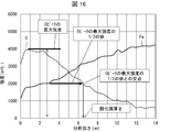
- FIG. 16 is a graph showing the relationship between the analysis depth from the surface of the steel sheet before hot dip coating and the strengths of Fe and O measured by Auger electron spectroscopy.
- the horizontal axis represents the analysis depth of the oxide film and the vertical axis represents the vertical axis.
- a graph with intensity is obtained.
- the analysis depth when the peak value (maximum intensity) of the curve showing oxygen in the graph is shown is the thickness of the oxide film.
- the thickness of the oxide film formed on the surface of the steel sheet can be reduced by, for example, pickling treatment.
- pickling treatment for example, an acidic fluid such as hydrochloric acid, sulfuric acid or mixed acid (mixed solution of hydrochloric acid and nitric acid) is used, temperature: 50 to 80 ° C., concentration: 5 to 25% by mass, contact time between the acidic fluid and the steel sheet It can be set to 10 to 180 seconds.
- the temperature of the steel sheet before entering the hot dip bath may be room temperature.
- the temperature of the steel sheet may be, for example, room temperature to 700 ° C.
- the steel sheet may be subjected to a heat treatment, a reduction treatment, a flux treatment, or the like, if necessary, before the hot dipping treatment.
- hot dip plating bath As the hot dip plating bath in the present embodiment, various known hot dip plating baths can be used. Examples of the hot-dip plating bath include a zinc (Zn) -based plating bath, a Zn-aluminum (Al) -based plating bath, a Zn-Al-magnesium (Mg) -based plating bath, and a Zn-Al-Mg-silicon (Si) -based plating.
- Zn zinc
- Al Zn-aluminum
- Mg Zn-Al-magnesium
- Si Zn-Al-Mg-silicon
- Examples thereof include a bath, an Al-based plating bath, an Al-Si-based plating bath, a Zn-Al-Si-based plating bath, a Zn-Al-Si-Mg-based plating bath, and a tin (Sn) -Zn-based plating bath.
- the temperature of the hot dip bath in this hot dip plating method may be the same as the temperature of the hot dip bath used in the known hot dip plating method.
- the molten plating bath is preferably a Zn-based plating bath in order to enhance the plating adhesion on the surface of the steel sheet after the hot dipping.
- the hot dip plating bath in one embodiment of the present invention has a Zn concentration of 40% or more.
- FIG. 1 is a schematic diagram showing a hot dipping apparatus 1 for carrying out the hot dipping method in the present embodiment.
- the hot-dip galvanizing apparatus 1 includes an ultrasonic horn (vibration generator) 10, an ultrasonic power source device D1, a hot-dip galvanizing bath 20, and a measuring device 30.
- the ultrasonic horn 10 is provided with an ultrasonic transducer 11.
- the steel plate 2 is fixed to the tip of the ultrasonic horn 10 with bolts 12.
- the ultrasonic power supply device D1 includes an oscillator 13, a power amplifier 14, and a power meter 15.
- the oscillator 13 generates an AC signal having an arbitrary frequency
- the power amplifier 14 amplifies the AC signal to generate an ultrasonic signal.
- the ultrasonic horn 10 receives the ultrasonic signal supplied via the power meter 15. As a result, the ultrasonic transducer 11 vibrates ultrasonically.
- the steel plate 2 connected to the ultrasonic horn 10 vibrates due to the vibration of the ultrasonic vibrator 11.
- the vibration of the steel sheet 2 causes a vibration activation effect in the hot-dip galvanizing bath 20, and a vibration activation region 23 is formed inside the hot-dip galvanizing bath 20 near the steel sheet 2.
- Hot-dip plating bath 20 is stored in pot 24 and contains hot-dip plating bath metal 21 and bath surface oxide 22.
- the vibration activation region 23 occurs in both the hot dip bath metal 21 and the bath surface oxide 22 in the hot dip bath 20.
- a waveguide rod 31 is inserted in the hot dip bath 20.
- One end of the waveguide rod 31 is arranged at an appropriate position inside the molten plating bath 20 so that the frequency of vibration of the molten plating bath metal 21 can be acquired, and the other end is connected to the vibration sensor 32.
- the vibration sensor 32 is a device that converts the vibration of the waveguide rod 31 into an electric signal using a piezoelectric element.
- the electrical signal transmitted from the vibration sensor 32 is amplified by the amplifier 33 and then transmitted to the spectrum analyzer 34.
- the spectrum analyzer 34 includes a display unit 34a. In this embodiment, the case where the spectrum analyzer 34 includes the display unit 34a will be described, but the display unit 34a may be replaced by an external device connected to the spectrum analyzer 34.
- the frequency of the ultrasonic oscillator 11 is set to 20 kHz, the output of the ultrasonic oscillator 11 is reduced, and vibration with a low sound pressure is applied to the hot dip bath 20.
- an acoustic spectrum as shown in FIG. 2 is displayed on the display unit 34a.
- the distance L1 between the waveguide rod 31 and the steel plate 2 was 10 mm, and the depth (distance from the tip to the bath surface of the hot dip plating bath 20) D1 of the waveguide rod 31 was 30 mm.
- FIG. 2 is a graph showing an example of an acoustic spectrum measured by the spectrum analyzer 34 included in the hot dipping apparatus 1. In the graph of FIG.
- the horizontal axis represents frequency and the vertical axis represents power value measured by the spectrum analyzer 34.
- the unit of the power value dBm (more accurately, dBmW: decibel milliwatt) represents the power in decibel value with reference to 1 mW.
- dBmW decibel milliwatt
- Such a power value can be used as an index representing the intensity of the acoustic spectrum.
- the magnitude of the value of the intensity (vertical axis in FIG. 2) in the acoustic spectrum corresponds to the magnitude of the sound pressure in the hot dip bath 20. Therefore, the peak of intensity in the acoustic spectrum corresponds to the peak of sound pressure.
- a peak showing a fundamental tone (frequency: 20 kHz) corresponding to the vibration applied to the hot dip bath 20 and a peak showing a harmonic (frequency that is an integral multiple of the fundamental tone) are mainly present.
- the frequency of the fundamental tone is defined as the fundamental frequency f
- the range (width) of the frequencies at which the acoustic spectrum is measured is defined as the measurement frequency band.
- the intermediate frequency (specifically, 3 / 2f, 5 / 2f, 7 / 2f, 9 / 2f) of each of the fundamental frequency f and a plurality of overtone frequencies (integer overtones: 2f, 3f, 4f, 5f) is determined.
- the range of the width of is the overtone band (specific frequency band).
- a range of a predetermined width from the intermediate frequency between the fundamental frequency f and the overtone frequency 2f is also referred to as an overtone band.
- the predetermined width of the inter-harmonic band is set to a range of 1 / 3f centering on the intermediate frequency.
- this predetermined width is not necessarily limited to this, and is appropriately set so as to be the frequency band between adjacent peaks among the main peaks in the acoustic spectrum (peaks at the fundamental frequency and peaks at the overtone frequency). do it.
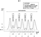
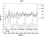
- FIG. 3 is a graph showing an example of an acoustic spectrum measured by the spectrum analyzer included in the hot dipping apparatus 1 when the ultrasonic wave output is changed.
- the horizontal axis represents frequency (Hz) and the vertical axis represents intensity (dBm).
- the fundamental frequency is set to 20 kHz and the ultrasonic output is changed to 0.1 W to 30 W.
- the output of the ultrasonic transducer 11 when the output of the ultrasonic transducer 11 was changed from 0.1 W to 30 W, the higher the output, the more the intensity of the acoustic spectrum increased over the entire frequency range. Further, when vibration is not applied to the hot dip bath 20 (the output of the ultrasonic transducer 11 is 0 W), the intensity of the acoustic spectrum measured by the spectrum analyzer can be regarded as noise. In this measurement system, the level (noise level) when no ultrasonic vibration was applied was ⁇ 100 dBm.
- the acoustic spectrum measured by the spectrum analyzer has a peak at the fundamental frequency (20 kHz) and a peak at the overtone frequency, and the intensity between these peaks (interharmonic band). Increase and decrease.
- the intensity between these peaks (interharmonic band).
- the inter-harmonic band there were some peaks with relatively small intensity, and the peak frequencies of these peaks varied variously depending on the output.
- the present inventors have found that there is a relationship between the strength (increase and decrease in strength) in the interharmonic band and the plateability of the steel sheet immersed in the hot dip plating bath 20. Specifically, it is as follows.
- the average value of the intensities in the inter-harmonic band may be referred to as inter-harmonic average intensity.
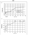
- FIG. 4 is a graph showing the influence of ultrasonic output on the average intensity of the entire measurement frequency band in the acoustic spectrum and the average intensity between overtones.
- the horizontal axis represents the ultrasonic wave output and the vertical axis represents the average intensity.
- the ultrasonic wave output is 10 W or less
- the inter-harmonic average intensity is smaller than the average intensity in the entire measurement frequency band.
- the ultrasonic wave output is 20 W or more
- the average intensity in the entire measurement frequency band and the interharmonic average intensity become equal to each other.
- the above noise level was evaluated as a reference. That is, the average intensity of the entire measurement frequency band and the inter-harmonic average intensity are evaluated as the signal intensity ratio with respect to the noise level. Then, the relationship between the ratio of the average intensities and the output was summarized. The result will be described below with reference to FIG.
- FIG. 4 (b) is a graph showing the influence of ultrasonic output on the intensity ratio of the interharmonic average intensity (noise standard) to the average intensity (noise standard) of the entire measurement frequency band in the acoustic spectrum.
- the ultrasonic output is plotted on the horizontal axis and the intensity ratio is plotted on the vertical axis.
- the intensity ratio (equation (1) described later) may be referred to as a characteristic intensity ratio.
- the above characteristic intensity ratio increased as the ultrasonic output increased from 0.1 W to 20 W.
- the characteristic intensity ratio became about 1 and became almost constant.
- the present inventors performed hot-dip plating of the steel sheet 2 by using the hot-dip galvanizing apparatus 1 while changing the ultrasonic output in various ways. As a result, it has been found that when the hot dip plating is performed under the condition that the characteristic strength ratio is larger than 0.2, the wettability of the steel sheet 2 is improved. That is, the reactivity between the surface of the steel sheet 2 and the hot-dip bath metal 21 can be improved by applying the vibration in the hot-dip bath 20 to satisfy the above condition. Specifically, the non-plating rate on the surface of the plated product after hot dipping can be less than 10%.
- the hot dip plating method is to allow a steel material to enter a plating bath which is a hot metal and to apply vibration to the hot metal while the steel material is in contact with the hot metal.
- the method includes a plating step of coating the steel material with the molten metal.
- the frequency of the vibration applied to the plating bath is the fundamental frequency.
- the vibration is applied so that the acoustic spectrum measured in the plating bath satisfies the relationship of the following formula (1): (IB-NB) / (IA-NA)> 0.2 (1) here, IA: Average value of sound pressure in the entire measurement frequency band IB: (i) Between sound pressure peak at the fundamental frequency and sound pressure peak at the second overtone frequency, and (ii) integer overtone frequencies (2 or more) Of the sound pressure peaks adjacent to each other among the peaks of the sound pressure in the specific frequency band NA: the average value of the sound pressure when the vibration is not applied in the entire measurement frequency band NB: It is the average value of the sound pressure in the specific frequency band defined for the IB when the vibration is not applied).
- the ultrasonic horn 10 imparts the vibration of the frequency of 20 kHz to the steel plate 2 by vibrating the ultrasonic transducer 11.
- the ultrasonic horn 10 may apply vibration of a frequency of 15 kHz to 150 kHz to the steel plate 2, for example.
- the intensity of vibration applied to the steel plate 2 by the ultrasonic horn 10 is set so that an acoustic spectrum satisfying the relationship of the above formula (1) is generated in the hot dip plating bath.
- what is the output of the ultrasonic transducer 11 and whether the acoustic spectrum satisfying the relationship of the above formula (1) is generated in the hot dip bath is determined for each condition such as the steel plate and the hot dip bath 20. You should check it beforehand.
- the predetermined condition is satisfied (the relationship of the above formula (1) is satisfied) while the steel sheet 2 and the hot-dip bath 20 are in contact with each other.
- the vibration is applied to the steel plate 2.
- the bath surface oxide 22 and the atmosphere caught in the hot-dip galvanizing bath 20 are dispersed in the bath. That is, the reaction inhibiting part is dispersed in the bath.
- mass transfer is promoted at the interface between the steel plate 2 and the hot-dip galvanizing bath 20, and the effect of reducing the thickness of the boundary layer or increasing the mass transfer speed is brought about. This ensures the wettability of the plating between the steel plate 2 and the hot dip bath 20.
- the reaction between the molten plating bath metal 21 and the steel plate 2 proceeds smoothly.
- the plating wettability of the steel sheet 2 can be improved. Therefore, it is possible to provide a hot-dip plating method in which the wettability of the hot-dip galvanized bath metal 21 and the steel sheet 2 is good and the energy consumption can be reduced more than ever before.
- the hot-dip plating method according to the aspect of the present invention, it is not necessary to perform the flux treatment. Therefore, the running cost can be reduced and the work environment can be improved.
- the hot-dip plating method in one aspect of the present invention when a new hot-dip plating facility is newly introduced, the cost and materials for installing the heating furnace are unnecessary, and the introduction cost can be reduced. Further, since the heating furnace has a long furnace length, it is not necessary to install the heating furnace, so that the total length of the hot dip plating equipment can be shortened.
- either the heat treatment or the reduction treatment before the hot-dip plating treatment (plating step) may be omitted, or both of them may be omitted.
- the steel plate 2 may be subjected to a heat treatment and a reduction treatment that are lighter than conventional ones before the plating step. In this case, energy consumption in both of those treatments is reduced. The amount can be reduced.
- the steel plate 2 may be subjected to various pretreatments before the hot dip plating treatment. For example, it does not matter if a reduction treatment is performed as a pretreatment for the plating step. If necessary, the steel plate 2 may be subjected to degreasing treatment or pickling treatment, or both of them may be performed (see Embodiment 4 described later). In the present hot dipping method, degreasing treatment and pickling treatment may be performed on the steel sheet 2 as pretreatment for the plating step, and at least degreasing treatment is particularly preferable. A pickling treatment may be performed subsequent to the degreasing treatment.
- the hot dip plating method includes a film thickness adjusting step of performing a pretreatment for reducing the thickness of the oxide film formed on the surface of the steel sheet 2 prior to the plating step.
- the film thickness adjusting step the thickness of the oxide film formed on the surface of the steel sheet 2 is reduced by, for example, subjecting the steel sheet 2 to pickling.
- the inventors of the present invention have performed a hot dip bath 20 so as to satisfy the relationship of the above formula (1) with respect to the steel sheet 2 in which the thickness of the oxide film is variously changed by performing pretreatment such as pickling treatment.
- Hot dip plating was performed while applying vibration to the inside.
- the plating adhesion of the steel sheet 2 is improved.
- the plated product after hot-dip plating is bent, and the plating removal test (see the description of Example 1 below) is performed, and the plating removal rate can be less than 10%.
- the plating peeling rate can be less than 5% and the plating peeling rate can be 0%.
- the hot-dip plating bath 20 it is preferable to use a hot-dip Zn-based plating bath containing 40 mass% or more of Zn.
- a steel material is allowed to enter a plating bath which is a hot-melt metal to coat the hot-melt metal with the hot-melt metal.
- This hot dip plating method comprises a film thickness adjusting step of performing a pretreatment for reducing the thickness of an oxide film formed on the surface of the metal material, and the steel material coming into contact with the molten metal after the film thickness adjusting step.
- a plating step of coating the steel material with the molten metal while applying vibration to the plating bath is performed.
- the frequency of the vibration applied to the plating bath is the fundamental frequency.
- the vibration is applied so that the acoustic spectrum measured in the plating bath satisfies the relationship of the following formula (1): (IB-NB) / (IA-NA)> 0.2 (1) here, IA: Average value of sound pressure in the entire measurement frequency band IB: (i) Between sound pressure peak at the fundamental frequency and sound pressure peak at the second overtone frequency, and (ii) integer overtone frequencies (2 or more) Of the sound pressure peaks adjacent to each other among the peaks of the sound pressure in the specific frequency band NA: the average value of the sound pressure when the vibration is not applied in the entire measurement frequency band NB: It is the average value of the sound pressure in the specific frequency band defined for the IB when the vibration is not applied).
- the steel plate 2 whose oxide film is thinned by the pretreatment is subjected to vibration in the hot-dip plating bath 20 so as to satisfy the relationship of the above-mentioned formula (1).
- Hot-dip while applying.
- the reaction layer 7 can be preferably formed on the surface of the steel sheet 2 after hot dipping, and the steel sheet 2 and the plating layer are relatively firmly bonded to each other via the reaction layer 7.
- the plating adhesion of the steel sheet 2 can be improved. Therefore, it is possible to provide a hot-dip plating method that has good plating adhesion on the steel sheet 2 after hot-dip galvanizing and that can reduce energy consumption more than before.
- the measurement frequency band may include the fundamental frequency and have a frequency width that is four times or more the fundamental frequency.
- the measurement frequency band may be 10 kHz or more and 90 kHz or less.
- a vibration generator (ultrasonic horn 10) is used to apply the vibration to the plating bath, and the output of the vibration generator may be 0.5 W or more.
- the output of the vibration generator may be 0.5 W or more and 30 W or less, and the frequency of vibration applied to the hot dip bath 20 via the steel plate 2 may be 15 kHz or more and 150 kHz or less.
- the vibration generator applies vibration with a frequency of 15 kHz or more and 150 kHz or less to the hot dipping bath 20, and the output may be 1 W or more and 30 W or less, or may be 5 W or more and 30 W or less.
- the time for applying the vibration in the plating bath using the vibration generator may be 2 seconds or more and 90 seconds or less.
- the steel plate 2 may have a temperature (inlet temperature) immediately before being immersed in the hot dip bath 20 at room temperature, for example, 100 ° C. or lower, or 50 ° C. or lower. May be.
- the acoustic spectrum in the plating bath is measured using a vibration detection device (eg, vibration sensor 32, amplifier 33, spectrum analyzer 34).
- the distance between the vibration detection point and the steel plate 2 in the plating bath may be 1 mm or more and 10 mm or less. The distance is measured in a state in which the steel plate 2 is immersed in the hot dip bath 20 before the vibration of the ultrasonic horn 10 is started.
- Example 1 An example of the hot dipping method according to the first embodiment of the present invention will be described below.
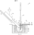
- FIG. 5 is a schematic diagram showing an example of a hot-dip plating apparatus used when the hot-dip plating method according to an aspect of the present invention is applied to dobu-zuke plating under an air atmosphere.
- the hot dipping apparatus 40 has a carbon crucible 42 housed inside a crucible furnace 41, and heats the carbon crucible 42 by causing resistance heating in a heating zone 43.
- the molten plating bath metal 21 is stored in the carbon crucible 42, and the bath surface oxide 22 is formed on the surface of the molten plating bath metal 21.
- the surface of the hot dip bath metal 21 is in the atmosphere.
- the hot dipping apparatus 40 includes the ultrasonic horn 10, and the steel plate 2 is fixed to the tip of the ultrasonic horn 10.
- the ultrasonic transducer 11 of the ultrasonic horn 10 receives the ultrasonic signal supplied from the ultrasonic power supply device D1 (including the oscillator 13, the power amplifier 14, and the wattmeter 15), and the ultrasonic power supply device D1 operates to receive the ultrasonic signal. Vibration is applied to the steel plate 2 with the set output.
- ultrasonic oscillator 11 a commercially available bolted Langevin type oscillator can be used.
- ultrasonic horn 10 an ultrasonic horn made of aluminum, titanium, ceramics, or the like can be used.
- the hot dipping apparatus 40 has a waveguide rod 51, an acoustic emission sensor (hereinafter, may be referred to as an AE sensor) 52, and a measuring apparatus 50 (corresponding to the measuring apparatus 30 in FIG. 1) for measuring an acoustic spectrum.
- the measuring unit 53 is provided.
- the measuring unit 53 includes a spectrum analyzer and an amplifier.
- One end of the waveguide rod 51 is immersed in the molten plating bath metal 21, and the other end is connected to the AE sensor 52.
- the various equipment used for the hot dipping apparatus 40 in this embodiment is specifically as follows.
- Ultrasonic vibration supply system ⁇ Ultrasonic transducer 11: Honda Electronics, bolted Langevin type transducer ⁇ Ultrasonic horn 10: Material ⁇ Aluminum alloy A2024A> -Oscillator 13: 33220A, manufactured by Agilent Technology Co., Ltd. ⁇ Power amplifier 14: M-2141, manufactured by Mestec Co., Ltd. ⁇ Electricity meter 15: PW-3335 manufactured by Hioki Electric Co., Ltd. (Ultrasonic vibration measurement system) -Waveguide 51: Material ⁇ SUS430>, ⁇ 6mm x 300mm ⁇ AE sensor 52: AE-900M, manufactured by NF Circuit Design Block Co., Ltd. ⁇ Amplifier: AE9922 manufactured by NF Circuit Design Block Co., Ltd. Spectrum analyzer: E4408B manufactured by Agilent Technologies, Inc.
- steel plate 2 (plating base material)
- carbon steel steel (steel type A and steel type B) shown in Table 1 below or stainless steel (steel type C to steel type F) shown in Table 2 below was used.
- Steel types A to F are all annealed materials.
- FIG. 17 is a schematic diagram for explaining the plating adhesion test. As shown in (a) of FIG. 17, the steel sheet after hot dip coating was used as the test material 200, and the test material 200 was first subjected to 0T adhesion bending processing (180 ° bending processing). Then, after the cellophane tape 210 was attached to the bent portion 201 to be in close contact with it, the cellophane tape 210 was peeled off.
- the peeled cellophane tape 210 was attached to Xerox paper. Then, a black-and-white binarization process was performed on the imaged image of the Xerox paper to which the cellophane tape 210 was attached. From the image after the binarization process, the area A of the portion 211 of the cellophane tape 210 that was in close contact with the bending portion 201 was calculated, and the plating layer 230 separated from the bending portion 201 attached to the cellophane tape 210 was calculated. Area B was calculated. Then, the value obtained by the calculation of (B / A) ⁇ 100 was calculated as the plating peeling rate. The plating adhesion of the test material 200 was evaluated according to the following criteria, and a rating of ⁇ or higher was passed.
- Plating peeling rate is 0% ⁇ : Plating peeling rate is more than 0% and less than 5% ⁇ : Plating peeling rate is 5% or more and less than 10% ⁇ : Plating peeling rate is 10% or more and less than 80% xx: Plating peeling rate is 80% or more.
- Example 1-1 Zn-Al-Mg type hot dip bath type is used, plating wettability
- the steel plates A to F shown in Table 1 and Table 2 were respectively subjected to a pre-treatment of alkali degreasing and pickling treatment using 10% hydrochloric acid.
- the pre-treated steel plates were attached to the tips of the ultrasonic horns 10 respectively, and were immersed in a Zn--Al--Mg-based hot dip bath at a depth of 60 mm (in other words, immersed in the bath in the depth direction of the plating bath).
- the length of the steel plate which is present) was soaked, and the soaking time was set to 100 seconds to carry out dobu-zuke plating.
- the application of the vibration was started 10 seconds after the immersion of the steel sheet attached to the tip of the ultrasonic horn 10 into the hot dip plating bath, and the vibration was applied for 90 seconds.
- the composition of the hot dip plating bath was 6 mass% Al, 3 mass% Mg, 0.025 mass% Si, and the balance Zn.
- the temperature of the hot dip bath was 380 ° C. to 550 ° C., and when vibration was applied to the hot dip bath, the fundamental frequency and the output of the ultrasonic vibrator 11 were changed.
- dobuzuke plating was performed without applying vibration to the hot dip bath.
- FIG. 6 is a side view showing the state of the sample material 3 after plating. As shown in FIG. 6, the test material 3 after plating is provided with a hot-dip plated region 3a. Further, a non-plated portion 4 which is not subjected to hot dip plating may exist in a part of the plated region 3a.
- the depth of the portion immersed in the hot dip bath is L11, and the width of the sample material 3 is L12.
- L11 ⁇ L12 ⁇ 2 is an ideal plating area ⁇ .
- the area ⁇ of the unplated portion 4 is measured using a known area measuring means.
- the area ⁇ of the unplated portion 4 is an area measured on both plated surfaces (both plate surfaces) of the sample material 3.
- the non-plating rate was calculated by calculating ( ⁇ / ⁇ ) ⁇ 100.
- the plating property of the sample 3 was evaluated based on the following criteria, and the evaluation of ⁇ or more was regarded as acceptable.
- Non-plating rate is 0% ⁇ : Non-plating rate is more than 0% and less than 1% ⁇ : Non-plating rate is 1% or more and less than 10% X: Non-plating rate is 10% or more and less than 80% XX: Non-plating rate is 80% or more.
- the plating base material is a steel plate, and whether or not the plating base material is heated means whether or not the steel plate is heated before the hot dip plating. Further, the inlet temperature means the temperature of the steel sheet at the time of charging into the hot dip bath.
- the sound intensity (noise standard) in the table is obtained by IA-NA, and the average intensity between integer overtones (that is, the average intensity between noise overtones) is obtained by IB-NB.
- the ratio (characteristic intensity ratio) of is determined by (IB-NB) / (IA-NA) (for these symbols, see the above-mentioned mathematical expression (1)). The above is the same in the following in the present specification.
- the vibration applied to the hot dip coating bath is too weak (sound pressure is too low)
- the acoustic spectrum within the range of the present invention is not measured in the hot dip bath, and No. 3 in Table 3 is not measured.
- the non-plating rate of the plated product was 10% or more.
- the non-plating rate of the plated product was 80% or more.
- Example 1-1-1 Using Zn-Al-Mg type hot dip bath type, plating adhesion
- the steel sheet A shown in Table 1 was subjected to pickling treatment to adjust various oxide film thicknesses, and then subjected to dobuzuke plating. The conditions other than this were the same as in Example 1-1 above.
- the plating adhesion was evaluated as described above using the sample after dobu-zuke plating as a test material. The test results are summarized in Table 4.
- the thickness of the oxide film is set within the range of the present invention, and vibration is generated in the hot-dip plating bath under the condition that an acoustic spectrum within the range of the present invention is measured in the hot-dip plating bath.
- the plating adhesion of the steel sheet was improved, and the plating peeling rate as a result of performing the plating adhesion test on the plated product was less than 10%.
- the plating peeling rate was 0% as a result of the plating adhesion test performed on the plated products.
- the vibration applied in the hot dip bath is too weak (sound pressure is too low), even if the thickness of the oxide film is within the range of the present invention, it is within the range of the present invention in the hot bath.
- the acoustic spectrum of No. 2 in Table 4 was not measured.
- the plating peeling rate of the plated product was 10% or more as a result of the plating adhesion test.
- the steel plate is applied while vibrating in the hot-dip plating bath under the condition that the acoustic spectrum within the range of the present invention is measured in the hot-dip plating bath. No.
- Example 1-1-2 Zn-Al-Mg based hot dip bath type is used, plating adhesion and pickling conditions are changed
- Steel plate A shown in Table 1 was subjected to pickling treatment using an acid other than hydrochloric acid to adjust the thickness of various oxide films, and then subjected to dobuzuke plating.
- As a mixed solution of hydrochloric acid and nitric acid so-called aqua regia, which is a mixture of hydrochloric acid (HCl) at 7.5% by mass, nitric acid (HHO 3 ) at 2.5% by mass, and water (H 2 O) at 90% by mass, is used.
- aqua regia which is a mixture of hydrochloric acid (HCl) at 7.5% by mass, nitric acid (HHO 3 ) at 2.5% by mass, and water (H 2 O) at 90% by mass, is used.
- the conditions other than this were the same as in Example 1-1 above.
- the plating adhesion was evaluated as described above using the sample after do
- Example 1-2 Using Al-Si type hot dip plating bath type, plating wettability
- Al-9 mass% Si-2 mass% Fe-based plating bath as the hot dip plating bath
- various steel plates shown in Table 1 and Table 2 were subjected to dobu-zuke plating.
- the temperature of the hot dip bath is 630 to 700 ° C.
- the dipping time of the steel plate in the hot dip bath is 12 seconds
- vibration is applied 10 seconds after the dipping of the steel plate into the hot dip bath is started.
- the fundamental frequency was set to 15 kHz
- the output of the ultrasonic transducer 11 was changed to 10 W or 0.05 W to 0.3 W.
- the conditions other than these were the same as in Example 1-1 above.
- the test results are summarized in Table 6.
- the vibration applied to the hot dip bath is too weak (sound pressure is too low)
- the acoustic spectrum within the scope of the present invention is not measured in the hot dip bath, and No. 6 in Table 6 is measured.
- the non-plating rate of the plated product was 10% or more.
- No. 6 in Table 6 was used.
- the non-plating rate of the plated product was 80% or more.
- Example 1-3 Various kinds of hot dip plating baths are used, plating wettability
- Example 2 Example 2-3 of the third embodiment were used as the hot-dip galvanizing baths, and various steel sheets A to F shown in Tables 1 and 2 were subjected to dobu-zuke plating.
- the compositions of the hot dip baths M1 to M10 are shown in Table 11 of Example 2, and the compositions of the hot dip bath M12 are shown in Table 12 of Example 2.
- the plating bath type M11 is an Al-2 mass% Fe-based plating bath, and the bath temperature is 700 ° C.
- the plating bath type M11 used in the test shown in Table 6 is Al-9 mass% Si- Unlike the 2 mass% Fe-based plating bath, Si is not added).
- the dipping time of the steel sheet in the hot dip coating bath was 12 seconds.
- the vibration was started 10 seconds after the dipping of the steel sheet in the hot dipping bath was started, and the vibration was given for 2 seconds.
- Example 1-3 the basic frequency was set to 15 kHz and the output of the ultrasonic vibrator 11 was kept constant at 20 W, and vibration was applied to the molten plating bath.
- the comparative example dobu-zuke plating was performed without applying vibration to the hot dipping bath.
- the steel plates A to F used had a plate thickness of 0.8 mm.
- Example 1-3 Various hot-dip bath types are used, plating adhesion
- the steel sheet A shown in Table 1 is subjected to pickling treatment with hydrochloric acid to reduce the thickness of the oxide film, and then used as a hot dip plating bath in Example 2 (Example 2-3) of the third embodiment. Dobuzuke plating was performed using various hot dip baths.
- the compositions of the hot dip baths M1 to M10 are shown in Table 11 of Example 2.
- Example 1-3 the basic frequency was set to 15 kHz and the output of the ultrasonic vibrator 11 was kept constant at 20 W, and vibration was applied to the molten plating bath.
- the comparative example dobu-zuke plating was performed without applying vibration to the hot dipping bath.
- the steel plate A having a plate thickness of 0.8 mm was used.
- the thickness of the oxide film is set within the range of the present invention, and vibration is generated in the hot-dip plating bath under the condition that the acoustic spectrum within the range of the present invention is measured in the hot-dip plating bath.
- the plating adhesion of the steel sheet was improved, and the plating peeling rate as a result of performing the plating adhesion test on the plated product was 0%.
- the acoustic spectrum was measured while fixing the distance L1 between the tip of the waveguide rod 31 and the surface of the steel plate 2 in the hot dipping bath 20 to 10 mm. According to a further study by the present inventor, it has been found that the characteristic intensity ratio in the acoustic spectrum can change with a change in the position where the acoustic spectrum is measured.
- 7A to 7E are graphs showing acoustic spectra measured by changing the output of the ultrasonic transducer 11 at each distance L1, where FIG. 7A is a distance L1 of 1 mm, and FIG. 7B is a graph.
- the distance L1 is 5 mm
- the distance L1 is 10 mm in (c)
- the distance L1 is 30 mm in (d)
- the distance L1 is 80 mm in (e).
- FIG. 8 is a graph showing the relationship between the distance L1 and the characteristic strength ratio. As shown in FIG. 8, as the distance L1 increases, the characteristic intensity ratio tends to decrease, and this tendency is particularly remarkable when the output is weak (specifically, 0.1 W and 0.5 W). is there. From this, for example, when the output is 0.1 W or 0.5 W, it can be said that the distance L1 is preferably 10 mm or less in order to detect the acoustic spectrum.
- the output is 0.5 W or more and the distance L1 is 10 mm or less.
- the ultrasonic horn 10 is used to apply vibration to the steel plate 2 with the steel plate 2 attached to the tip of the ultrasonic horn 10.
- vibration is applied to the vibration plate using the ultrasonic horn 10, and the steel plate 2 is passed through the hot dip bath 20. The difference is that it indirectly gives a vibration to.
- FIG. 9 is a schematic diagram showing a hot dipping apparatus 60 for carrying out the hot dipping method in the present embodiment.
- the hot-dip galvanizing apparatus 60 includes a gas reduction heating zone 61, a hot-dip galvanizing section 62, an ultrasonic horn 10, and a measuring device 50 for measuring an acoustic spectrum.
- the gas reduction heating zone 61 is provided with an atmospheric gas introducing portion 61a and a heating portion 61b, and can heat-treat the steel sheet 2 in a desired atmosphere.
- the space above the crucible furnace 41 is isolated from the atmosphere by a port flange 64 and an O-ring 65.
- An atmosphere gas introduction portion 66 is provided in a part of the port flange 64 so that the atmosphere in the hot dip coating portion 62 can be controlled.
- a gate valve 63 is provided between the gas reduction heating zone 61 and the hot dip coating 62.
- the steel plate 2 processed in the gas reduction heating zone 61 opens the gate valve 63 and is transferred to the hot-dip galvanizing section 62 without being exposed to the atmosphere.
- the steel sheet 2 enters the plating bath 21 after undergoing pretreatment such as atmosphere control and heat treatment in the gas reduction heating zone 61 above the gate valve 63.
- the vibration plate 70 is fixed to the tip of the ultrasonic horn 10 instead of the steel plate 2.
- the vibrating plate 70 is made of ordinary steel (the same steel type as the steel plate A in Table 1) and has a length of 150 mm, a width of 50 mm, and a thickness of 0.8 mm.
- the vibration of the vibrating plate 70 applies vibration to the molten plating bath metal 21.
- the steel plate 2 is vibrated via the hot dip bath metal 21. That is, the hot dipping device 60 indirectly applies vibration to the steel plate 2.
- the diaphragm 70 is not limited to the above materials.
- the vibrating plate 70 is preferably made of a material that has strong erosion resistance when immersed in a hot dip plating bath and does not have good wettability with respect to the hot dipping bath. For example, ceramics can be used.
- measuring device 50 Other configurations of the measuring device 50 and the like are similar to those of the above-described hot dipping device 40 (see FIG. 5), and thus detailed description thereof will be omitted.
- the hot dipping apparatus 60 as described above can be applied to a continuous hot dipping method. That is, in the continuous hot dip coating method, it is difficult to directly apply vibration to the steel plate, but it is possible to indirectly apply vibration to the steel plate 2 as in the hot dipping apparatus 60. Therefore, the results demonstrated by using the hot dipping apparatus 60 as described above can be applied to the continuous hot dipping method. An example of application to the continuous hot dip plating method will be specifically described later.
- Example 2 An example of the hot-dip plating method according to the third embodiment of the present invention will be described below.
- the hot dip plating apparatus 60 shown in FIG. 9 was used.
- Example 1 Various steel plates A to F (see Tables 1 and 2) are used as in Example 1, and a Zn—Al—Mg-based hot dip plating bath or an Al-9 mass% Si-2 mass% Fe-based plating bath is used. Was used to perform hot dip plating under various conditions.
- Example 2-1 No heat treatment in gas reduction heating zone 61
- Alkaline degreasing treatment was applied to each of the various steel sheets as a pretreatment.
- the hot dip plating bath the Zn-Al-Mg based plating bath in Example 1-1 of Example 1 and the Al-9% Si based plating bath in Example 1-2 of Example 1 were used.
- the atmosphere in the hot dip section 62 was changed to an air atmosphere, a nitrogen atmosphere, a 3% hydrogen-nitrogen atmosphere, or a 30% hydrogen-nitrogen atmosphere. Atmosphere control and heat treatment in the gas reduction heating zone 61 were not performed.
- the dipping time of the steel sheet in the hot dip coating bath is 12 seconds, and when vibrating the vibrating plate 70 by using the ultrasonic horn 10 to apply vibration to the hot dip coating bath, start dipping the steel sheet in the hot dipping bath.
- the application of vibration was started 10 seconds after, and the vibration was applied for 2 seconds.
- the fundamental frequency was set to 15 kHz and the output of the ultrasonic transducer 11 was kept constant at 30 W, and vibration was applied to the hot dip bath.
- the arrangement of the steel plate and the vibration plate in the hot dip plating bath was adjusted so that the distance (distance) between the vibration plate and the steel plate was 5 mm.
- the distance between the steel plate and the tip of the waveguide rod was 5 mm.
- Example 2-2 There is heat treatment in the gas reduction heating zone 61
- Example 2 described above except that the atmosphere control and heat treatment in the gas reduction heating zone 61 were performed, and the vibration was started for 2 seconds after starting the immersion of the steel sheet in the hot dip plating bath for 2 seconds. Hot-dip plating was performed in the same manner as in -1. The results of the test are summarized in Table 10.
- Hot-dip plating was performed in the same manner as in Example 2-1 except that the hot-dip plating baths having the compositions shown in Tables 11 and 12 below were used and the atmosphere in the hot-dip plating section 62 was a 3% hydrogen-nitrogen atmosphere. ..
- the plating bath type M11 is an Al-2 mass% Fe-based plating bath and the bath temperature is 700 ° C.
- the plating bath type M11 used in the tests shown in Table 6 is Al-9 mass% Si-2 mass% Fe. Unlike the system-based plating bath, Si is not added). The test results are summarized in Table 13.
- the hot dip plated steel sheet produced by the hot dip plating method of the present invention may have a base chemical conversion treatment film formed on the surface of the plating layer for improving corrosion resistance and film adhesion.
- the base chemical conversion coating is preferably an inorganic coating, and more specifically, a coating containing a valve metal oxide or hydroxide and a valve metal fluoride.
- valve metal refers to a metal whose oxide exhibits high insulation resistance.
- the valve metal element is preferably one or more elements selected from Ti, Zr, Hf, V, Nb, Ta, Mo and W.
- the base chemical conversion treatment film may contain a soluble or sparingly soluble metal phosphate or complex phosphate.
- the base chemical conversion coating may contain an organic wax such as a fluorine-based, polyethylene-based or styrene-based wax, or an inorganic lubricant such as silica, molybdenum disulfide or talc.
- the base chemical conversion coating may be an organic coating based on urethane resin, acrylic resin, epoxy resin, olefin resin, polyester resin or the like.
- the hot-dip plated steel sheet produced by the hot-dip plating method of the present invention on the surface of the plating layer, a polyester-based, acrylic resin-based, fluororesin-based, vinyl chloride resin-based, urethane resin-based, epoxy resin-based resin system
- the paint can be applied by methods such as roll coating, spray coating, curtain flow coating, and dip coating. Alternatively, it can also be used as a base material for film lamination when laminating a plastic film such as an acrylic resin film.
- a part of the ultrasonic horn is immersed in the hot dip bath, and vibration is applied to the hot dip bath from the tip of the ultrasonic horn.
- the vibration is indirectly transmitted from the tip of the ultrasonic horn to the steel sheet through the hot dip plating bath, and the steel sheet is subjected to doppling plating.
- FIG. 10 is a schematic diagram showing a hot dipping apparatus 80 for carrying out the hot dipping method in the present embodiment.
- the hot dip coating device 80 includes an elevating device 81, an ultrasonic horn 10A, a measuring device 50 for measuring an acoustic spectrum, and a carbon crucible 42 in which the hot dip bath metal 21 is stored. ing.
- the steel plate 2 is immersed in the hot dip plating bath 20 in the air and without heating the steel plate 2.
- the elevating device 81 is a device capable of immersing the steel plate 2 in the hot dip plating bath 20 while holding the steel plate 2 and pulling the steel plate 2 out of the hot dip bath 20.
- a known device may be used as the lifting device 81, and detailed description thereof will be omitted.
- the ultrasonic horn 10A includes an ultrasonic transducer 11, a tip portion 17, and a connecting portion 16 that connects the ultrasonic transducer 11 and the tip portion 17 together.
- the ultrasonic transducer 11 is fixed by a transducer fixing stage 19.
- the connection portion 16 has a length that facilitates resonance according to the frequency of the vibration generated by the ultrasonic transducer 11.
- the connecting portion 16 may be a simple adapter or a booster that amplifies the amplitude generated by the ultrasonic transducer 11 and transmits the amplified amplitude to the tip portion 17.
- the ultrasonic transducer 11 receives the ultrasonic signal transmitted from the ultrasonic power supply device D1 and vibrates ultrasonically. To do. This ultrasonic vibration is transmitted to the tip portion 17 via the connection portion 16, and the tip portion 17 imparts vibration to the hot dip bath 20.
- a vibrating surface 17A is formed at an end of the tip portion 17 farther from the connecting portion 16 in the longitudinal direction so that the cross-sectional shape of the end portion becomes an isosceles triangular shape, and the vibrating surface 17A is melted. It faces the surface of the steel plate 2 immersed in the plating bath 20.
- the tip 17 is preferably made of ceramic. This is to reduce deterioration of the tip portion 17 that may occur due to ultrasonic vibration of the tip portion 17 in the hot dip bath 20.
- the hot dipping device 80 may use an integrated ultrasonic horn instead of the ultrasonic horn 10A.
- the tip of the ultrasonic horn may be made of ceramics.
- the distance L2 between the vibrating surface 17A of the tip portion 17 and the surface of the steel plate 2 may be 0 mm or may be greater than 0 mm and 50 mm or less.
- the distance L2 of 0 mm means that the vibrating surface 17A and the surface of the steel plate 2 are in contact with each other before the ultrasonic horn 10A vibrates ultrasonically (that is, at the time of setting).
- the lifting device 81 can move the steel plate 2 in the horizontal direction, and the distance L2 can be adjusted by moving the steel plate 2 in the horizontal direction using the lifting device 81.
- the distance L2 is preferably more than 0 mm and 5 mm or less.
- the frequency and output of the vibration applied to the hot dipping bath 20 using the ultrasonic horn 10A are the same as those described in the first embodiment.
- Example 3 An example of the hot-dip plating method according to the fifth embodiment of the present invention will be described below.
- the hot dipping apparatus 80 shown in FIG. 10 described above was used.
- the various equipment used for the hot dipping apparatus 80 in this embodiment is specifically as follows.
- Ultrasonic vibration supply system ⁇ Ultrasonic transducer 11: Hielscher, 20 kHz transducer ⁇ Connecting portion 16 (booster): Material ⁇ Ti>, amplification factor 2.2 times, 1/2 wavelength type, length 126 mm -Tip 17: Material ⁇ Ti>, 1/2 wavelength type, length 250 mm ⁇ Ultrasonic power supply device D1: Hielscher, 20 kHz, 2 kW power supply (ultrasonic vibration measurement system) -Waveguide 51: Material ⁇ SUS430>, ⁇ 6mm x 300mm ⁇ AE sensor 52: AE-900M, manufactured by NF Circuit Design Block Co., Ltd. ⁇ Measuring unit 53 Amplifier: AE9922 manufactured by NF Circuit Design Block Co., Ltd. Spectrum analyzer: E4408B manufactured by Agilent Technologies, Inc.
- Example 1-1 ′ of Example 1 the steel sheet A shown in Table 1 was adjusted to various oxide film thicknesses by pickling treatment, and then a Zn—Al—Mg-based hot dip bath was used. Using this, dobu-zuke plating was performed under various conditions.
- the distance L2 was 0 mm to 50 mm, and the fundamental frequency was 20 kHz or 50 kHz.
- vibration is applied to the hot dip bath using the ultrasonic horn 10A
- vibration is applied 10 seconds after the steel plate 2 is immersed in the hot dip bath and vibration is applied for 2 seconds to 60 seconds. ..
- the ultrasonic transducer 11 has a built-in amplitude sensor for monitoring the amplitude of the ultrasonic transducer 11.
- a display device was used to receive the output from the amplitude sensor and display the output with a full scale of 5V. Since the magnitude of the amplitude of the ultrasonic transducer 11 is reflected in the output displayed by the display device, 5V of full scale is set as 100% of the output in the following, and is an index indicating the magnitude of the amplitude of the ultrasonic transducer 11. "Output%" was used as.
- the load on the ultrasonic power source is considered to be the steel sheet itself.
- the load on the ultrasonic power source is the steel sheet and the hot dip bath. Therefore, the vibration applying condition is expressed not by using the output (W) itself from the ultrasonic power source but by using “output%” which is an index indicating the amplitude of the ultrasonic vibrator when resonating.
- each test material was subjected to dobu-zuke plating using the hot dipping device 80 without applying vibration to the hot dipping bath.
- the test results are summarized in Table 14.
- the thickness of the oxide film is set within the range of the present invention, and vibration is generated in the hot dipping bath under the condition that the acoustic spectrum within the range of the present invention is measured in the hot dipping bath.
- the plating adhesion of the steel sheet was improved, and the plating peeling rate as a result of performing the plating adhesion test on the plated product was less than 10%.
- the thickness of the oxide film is out of the range of the present invention
- vibration is applied to the hot dip bath under conditions such that the acoustic spectrum within the range of the present invention is measured in the hot dip bath. No. in Table 14 even if the steel plate is plated with dobu-zuke.
- the plating peeling rate of the plated product was 10% or more as a result of the plating adhesion test.
- hot-dip plating was performed without applying vibration to the hot-dip plating bath, No. As indicated by 408, the plating layer was not sufficiently formed on the plated product, and the plating adhesion could not be tested.
- the hot-dip plating method in the present embodiment while using a continuous hot-dip galvanizing equipment to continuously pass the steel strip in the hot-dip galvanizing bath, a part of the ultrasonic horn is immersed in the hot-dip galvanizing bath to Place the tip of the ultrasonic horn in the vicinity. While applying vibration to the hot dip bath or the steel strip from the tip of the ultrasonic horn, the hot dip is continuously applied to the steel strip.
- FIG. 11 is a schematic diagram showing an example of hot-dip plating equipment 90A for carrying out the hot-dip plating method in the present embodiment.
- the hot-dip galvanizing equipment 90A has a configuration in which an ultrasonic horn 10B and a measuring device 50 are added to a general continuous hot-dip galvanizing equipment.
- 2 A of steel strips are immersed in the hot dip bath 20 through the snout 91.
- the steel strip 2A is passed through the hot-dip galvanizing bath 20 by a guide roll 92 and a support roll 93, then pulled up, and the amount of coating adhered is adjusted by gas blowing or the like.
- the steel strip 2A may be subjected to a pickling treatment or the like to remove the iron oxide layer on the surface of the steel strip 2A as a pretreatment for the plating process.
- the hot dip equipment 90A may be configured to heat the steel strip 2A to a temperature suitable for hot dip plating by a heating device (not shown) provided in the preceding stage of the snout 91.
- the hot-dip galvanizing equipment 90A does not have to be provided with a reduction heating device before the snout 91.
- ultrasonic vibration is applied to the hot-dip bath 20 using the ultrasonic horn 10B so that the wettability of the steel strip 2A can be reduced even if the surface of the steel strip 2A is not subjected to reduction treatment. Can be increased.
- the ultrasonic horn 10B is an integrated device including the ultrasonic transducer 11, the tip portion 17, and the connecting portion 16 in the ultrasonic horn 10A described in the fifth embodiment.
- the hot dip equipment 90A may use the ultrasonic horn 10A instead of the ultrasonic horn 10B.
- the ultrasonic horn 10B is arranged so that the tip of the ultrasonic horn 10B is immersed in the hot dip bath 20 and located near the steel strip 2A near the outlet of the snout 91. There is.
- the ultrasonic horn 10B preferably has a vibrating surface 17A formed by chamfering the end of the ultrasonic horn 10B closer to the steel strip 2A in the longitudinal direction.
- the vibrating surface 17A faces the surface of the steel strip 2A that passes through the hot dip bath 20. Thereby, the vibration can be efficiently transmitted from the ultrasonic horn 10B to the steel strip 2A while keeping the distance between the vibrating surface 17A and the surface of the steel strip 2A constant according to the passing direction.
- the hot-dip galvanizing equipment 90A in the hot-dip galvanizing bath 20, in the vicinity of the second surface of the steel strip 2A on the side opposite to the first surface of the steel strip 2A facing the vibrating surface 17A.
- the tip of the wavy rod 51 is arranged. It is preferable that the waveguide rod 51 is arranged along the passing direction of the steel strip 2A.
- the waveguide rod 51 may be provided with a protective tube or the like that covers a portion other than the tip of the hot dip bath 20 in order to reduce noise and the like in the acoustic spectrum.
- the distance L3 between the vibrating surface 17A and the surface of the steel strip 2A may be 0 mm, or may be greater than 0 mm and 50 mm or less.
- the distance L3 of 0 mm means that the vibrating surface 17A and the surface of the steel strip 2A are in contact with each other before the ultrasonic horn 10B vibrates ultrasonically (that is, at the time of setting).
- the steel strip 2A is vibrated at the same fundamental frequency as the ultrasonic horn 10B. It is possible to As a result, the plating wettability can be improved not only on the first surface of the steel strip 2A but also on the second surface.
- the frequency and output of the vibration applied to the hot dip bath 20 using the ultrasonic horn 10B are the same as those described in the first embodiment.
- FIG. 12 is the schematic which shows the hot-dip plating equipment 90B and hot-dip plating equipment 90C of a modification.
- the hot dip equipment 90B and the hot dip equipment 90C differ from the hot dip equipment 90A described above in that the ultrasonic horn 10B is disposed near the support roll 93.
- the ultrasonic horn 10B is arranged at a position after the steel strip 2A has been passed through the hot dip coating bath 20 and passed through the support roll 93. Even when the ultrasonic horn 10B is arranged in this manner, the ultrasonic wetness of the ultrasonic horn 10B to the molten plating bath 20 or the steel strip 2A can enhance the wettability of the plating of the steel strip 2A. ..
- the ultrasonic horns 10B in the hot dip equipment 90A to 90C may be combined so as to apply ultrasonic vibration to the hot dip bath 20 or the steel strip 2A using a plurality of ultrasonic horns 10B. .. It is sufficient to appropriately select a configuration that provides good plating properties of the steel strip 2A.
- the strip speed of the steel strip 2A is adjusted so that the plating property of the steel strip 2A becomes good. May be adjusted appropriately.
- Example 4 An example of the hot-dip plating method according to the sixth embodiment of the present invention will be described below.
- the hot dip plating equipment 90A shown in FIG. 11 was used.
- the various equipment used in the hot-dip plating equipment 90A in this embodiment is specifically as follows.
- Ultrasonic vibration supply system ⁇ Ultrasonic transducer 11: Hielscher, 20 kHz transducer ⁇ Connecting part 16 (adapter): material ⁇ Ti>, 1/2 wavelength type, length 126 mm -Tip 17: Material ⁇ Super Sialon>, dual wavelength type, length 500 mm ⁇ Ultrasonic power supply device D1: Hielscher, 20 kHz, 2 kW power supply (ultrasonic vibration measurement system) -Waveguide 51: Material ⁇ SUS430>, ⁇ 6mm x 300mm ⁇ AE sensor 52: AE-900M, manufactured by NF Circuit Design Block Co., Ltd. ⁇ Measuring unit 53 Amplifier: AE9922 manufactured by NF Circuit Design Block Co., Ltd. Spectrum analyzer: E4408B manufactured by Agilent Technologies, Inc.
- Example 1-1 ′ of Example 1 the steel sheet A shown in Table 1 was adjusted to various oxide film thicknesses by pickling treatment, and then a Zn—Al—Mg-based hot dip bath was used. Using this, dobu-zuke plating was performed under various conditions.
- the atmosphere inside the snout was changed to an air atmosphere, a nitrogen atmosphere, a 3% hydrogen-nitrogen atmosphere, or a 30% hydrogen-nitrogen atmosphere. Further, in the previous stage of the snout, the steel strip was heat-treated in a nitrogen atmosphere, a 3% hydrogen-nitrogen atmosphere, or a 30% hydrogen-nitrogen atmosphere.
- the distance L3 was 0 mm and the fundamental frequency was 20 kHz.
- the strip running speed of the steel strip in the hot-dip galvanizing bath was 20 m / min in the example with heat treatment before the snout, and 3 m / min in the example without heat treatment.
- the thickness of the oxide film is set within the range of the present invention, and vibration is generated in the hot-dip plating bath under the condition that the acoustic spectrum within the range of the present invention is measured in the hot-dip plating bath.
- the steel strip was subjected to hot-dip galvanizing using the continuous plating equipment while applying, the following results were obtained. Whether the steel strip is heated in an air atmosphere or a non-oxidizing atmosphere, and regardless of the atmosphere in the snout, the plating adhesion of the steel strip is improved, and the plating adhesion test is performed on the plated product. As a result, the plating peeling rate was 0%.
- the atmosphere in the snout is changed to the air atmosphere or the non-oxidizing atmosphere, and the steel strip is hot-dipped. No. of Table 15 is performed. As shown in 418 to 424, the plating peeling rate of the plated product was 80% or more as a result of the plating adhesion test.
- the atmosphere in the snout is set to the air atmosphere or the non-oxidizing atmosphere, and the steel strip is hot-dipped without vibration in the hot-dip plating bath.
- No. of Table 15 As shown by 425 to 431, the plating layer was not sufficiently formed on the plated product, and the plating adhesion could not be tested.
Landscapes
- Chemical & Material Sciences (AREA)
- Engineering & Computer Science (AREA)
- Chemical Kinetics & Catalysis (AREA)
- Materials Engineering (AREA)
- Mechanical Engineering (AREA)
- Metallurgy (AREA)
- Organic Chemistry (AREA)
- Inorganic Chemistry (AREA)
- Computer Hardware Design (AREA)
- Coating With Molten Metal (AREA)
- Application Of Or Painting With Fluid Materials (AREA)
- Glass Compositions (AREA)
Abstract
溶融めっきを施した後の金属材料の表面におけるめっき密着性が良好であるとともに、従来よりもエネルギー消費量の低減を図ることができる溶融めっき方法を提供する。溶融めっき方法は、金属材料の酸化膜の厚さを調整する前処理を施す膜厚調整工程と、音響スペクトルにおける測定周波数帯域全体の音圧の平均値(ノイズを除く)に対する、基本周波数の倍音周波数における音圧のピーク間の音圧の平均値(ノイズを除く)の比が0.2よりも大きくなるように振動を付与するめっき工程と、を含む。
Description
本発明は、金属材料の溶融めっき方法に関し、特に鋼材に対する溶融めっき方法に関する。
現在、溶融めっき製品の製造に用いられている方法(溶融めっき方法)は、連続式溶融めっき方法と浸漬めっき方法とに大別される。以下では、金属材料を代表して鋼材を例示し、鋼材に対する溶融めっき方法について説明する。
連続式溶融めっき方法は、コイル状の鋼材(金属帯)を連続的に溶融めっき浴に通板(浸漬および通過)させて、該鋼材をめっきする方法である。また、浸漬めっき方法は、いわゆる「どぶ漬けめっき」と称される方法であって、予め成形された鋼材にフラックスを付着させた後、当該鋼材を溶融めっき浴に浸漬させてめっきする方法である。
上記連続式溶融めっき方法の実施に用いられる設備(連続式溶融めっき設備)は、通常、前処理設備、還元加熱炉、溶融めっき浴部(溶融金属ポット)、および後処理設備を含む。上記前処理設備では、鋼材に付着している圧延油および汚れを除去する処理が行われる。上記還元加熱炉では、H2を含む雰囲気中にて鋼材を加熱することにより、該鋼材の表面に存在するFe酸化物の還元処理が行われる。上記溶融めっき浴部では、還元加熱炉にて処理された鋼材を、還元雰囲気内、または鋼材表面の再酸化を防止する雰囲気内に保持したまま溶融めっき浴に浸漬および通過させることにより、該鋼材に溶融めっきが施される。上記後処理設備では、溶融めっきされた鋼材に対して用途に応じて様々な処理が施される。
一方、どぶ漬けめっきの実施に用いられる設備(どぶ漬けめっき設備)は、予め成形された鋼材の油および汚れを除去する脱脂設備、Fe酸化物層(錆または黒皮と称される)を除去する酸洗設備、酸洗処理された鋼材にフラックスを付着させるフラックス設備、および上記フラックスの乾燥後の鋼材に溶融めっきを施す溶融めっき浴部を含む。必要に応じて、上記連続式溶融めっき設備と同様に、どぶ漬けめっき設備に後処理設備が付設される場合もある。上記フラックスは、鋼材と溶融めっき浴との反応性を良好にするために用いられる。
従来、溶融めっき方法において、溶融めっき後のめっき品(半製品)の表面におけるめっき欠陥(不めっきまたはピンホールと称される)の発生という問題が生じ得る。めっき欠陥とは、鋼材に溶融金属が付着せず該鋼材の表面にめっき金属が存在しない状態となっている部分のことである。めっき欠陥の発生には様々な要因が考えられ、その対策が長年講じられてきた。例えば、対策の一つとして、連続式溶融めっき方法における加熱処理(還元処理)後の金属帯に超音波振動を付与した状態にて溶融めっきを施す技術が提案されている(特許文献1、2を参照)。どぶ漬けめっきにおいても、やけ(合金層の露出)が原因となって不めっきが発生するという課題に対して、超音波を使用してどぶ漬けめっきを行う技術が提案されている(特許文献3を参照)。
一般に、連続式溶融めっき方法では、金属帯を溶融金属ポットに浸漬させる前段階において、上記還元加熱炉によって金属帯の材料自体の焼鈍処理および金属帯表面に存在する酸化膜の還元処理が行われる。該還元加熱炉では、酸化膜の還元のために、例えば窒素および水素の混合雰囲気下で金属帯の加熱処理が行われる。この加熱処理では、めっき製品の使用目的に応じて金属帯の加熱温度が設定され、金属帯と溶融めっき浴との反応性を良好にするために、少なくとも溶融めっき浴の温度以上に金属帯が加熱される。
上記還元加熱炉における処理によって金属帯表面の酸化膜が除去されるため、溶融めっき浴中にて、金属帯と溶融めっき浴との反応性が向上する。そのため、溶融めっきの施された金属帯を安定して生産することができる。
しかしながら、金属材料の成分または製造条件等の各種の要因によって、めっき品の表面にめっき欠陥が生じる場合があり、このことは、連続式溶融めっきを行う場合だけでなく、どぶ漬けめっきを行ってめっき品を製造する場合においても同様である。
また、近年、(i)溶融めっき方法の省エネルギー化、および(ii)クリーンな作業環境にて作業者が溶融めっき作業に従事すること、についての要望が益々高まっている。
連続式溶融めっき設備における上記還元加熱炉は、非常に大きな熱量を必要とし、かつ、雰囲気ガスとして用いられる窒素および水素を大量に消費する。このことは、特許文献1、2に記載の技術においても同様である。従来の連続式溶融めっき方法において、溶融めっき製品への要求(少めっき欠陥等)を満たしつつエネルギー消費量を低減することは容易では無い。
また、どぶ漬けめっき設備では、通常、良好なめっき性を確保するためにフラックス設備が設けられている。この場合、作業環境の観点から以下のような問題がある。すなわち、(i)フラックスの主成分となる塩化物(ZnCl2,NH4Cl等を含む)の取り扱いを要する、および(ii)フラックスが乾燥した後の金属材料を溶融めっき浴に浸漬した際に大量の白煙および臭気が発生する、等の問題がある。どぶ漬けめっき設備において、溶融めっき製品への要求を満たしつつ作業環境の改善を図ることは難しい。
本発明の一態様は、上記従来の問題点に鑑みなされたものであって、その目的は、溶融めっきを施した後の金属材料の表面におけるめっき密着性が良好であるとともに、従来よりもエネルギー消費量の低減および作業環境の改善を図ることができる溶融めっき方法を提供することにある。
上記の課題を解決するために、本発明の一態様における溶融めっき方法は、溶融金属であるめっき浴中に金属材料を進入させて、上記金属材料に上記溶融金属を被覆させる溶融めっき方法であって、上記金属材料の表面に形成された酸化膜の厚さを低減する前処理を施す膜厚調整工程と、上記膜厚調整工程の後、上記溶融金属に上記金属材料が接触している間に上記めっき浴中に振動を付与しつつ上記金属材料に上記溶融金属を被覆させるめっき工程と、を含み、上記めっき浴に付与する上記振動の周波数を基本周波数として、上記めっき工程では、上記めっき浴中にて測定される音響スペクトルが下記式(1)の関係を満たすように、上記振動を付与することを特徴としている。
(IB-NB)/(IA-NA)>0.2 ・・・(1)
(ここで、
IA:測定周波数帯域全体における音圧の平均値
IB:(i)上記基本周波数における音圧のピークと2倍音周波数における音圧のピークとの間、並びに、(ii)複数の倍音周波数における音圧のピークのうち隣り合うピーク間、の特定周波数帯域における音圧の平均値
NA:上記測定周波数帯域全体における、上記振動を付与していない場合の音圧の平均値
NB:上記IBに関して規定される上記特定周波数帯域における、上記振動を付与していない場合の音圧の平均値
である)。
(ここで、
IA:測定周波数帯域全体における音圧の平均値
IB:(i)上記基本周波数における音圧のピークと2倍音周波数における音圧のピークとの間、並びに、(ii)複数の倍音周波数における音圧のピークのうち隣り合うピーク間、の特定周波数帯域における音圧の平均値
NA:上記測定周波数帯域全体における、上記振動を付与していない場合の音圧の平均値
NB:上記IBに関して規定される上記特定周波数帯域における、上記振動を付与していない場合の音圧の平均値
である)。
本明細書において、上記のように(IB-NB)/(IA-NA)にて求められる強度比を、特徴的強度比と称することがある。本発明者らは、表面に形成された酸化膜の厚さが前処理によって低減された金属材料に対して、上記特徴的強度比が0.2よりも大きくなる条件にて溶融めっきを行うことにより、金属材料のめっき密着性が向上することを見出した。
本発明の一態様によれば、溶融めっきを施した後の金属材料の表面におけるめっき密着性が良好であるとともに、従来よりもエネルギー消費量の低減および作業環境の改善を図ることができる溶融めっき方法を提供することができる。
以下、本発明の実施の形態について、図面を参照して説明する。なお、以下の記載は発明の趣旨をよりよく理解させるためのものであり、特に指定のない限り、本発明を限定するものでは無い。また、本出願において、「A~B」とは、A以上B以下であることを示している。本出願における各図面に記載した構成の形状および寸法は、実際の形状および寸法を必ずしも反映させたものではなく、図面の明瞭化および簡略化のために適宜変更している。
(用語の定義)
本明細書において、溶融めっき浴を構成する各種の溶融された金属(溶融金属)を「溶融めっき浴金属」と称することがある。また、本明細書において、溶融めっき浴を用いて溶融めっきを施される対象としての鋼材の材質および形状は、格別の記載が無い限り特に限定されない。また、「鋼板」は、不都合の無い限り「鋼帯」と読み替えてもよい。
本明細書において、溶融めっき浴を構成する各種の溶融された金属(溶融金属)を「溶融めっき浴金属」と称することがある。また、本明細書において、溶融めっき浴を用いて溶融めっきを施される対象としての鋼材の材質および形状は、格別の記載が無い限り特に限定されない。また、「鋼板」は、不都合の無い限り「鋼帯」と読み替えてもよい。
なお、一般に溶融めっき方法において「めっき性」とは、金属材料と溶融めっき浴とのめっき濡れ性、および、金属材料と金属材料の表面に形成されためっき層との間のめっき密着性の両方を指してめっき性と呼ぶことがある。本明細書においても、従来と同様の意味で、「めっき性」、「めっき濡れ性」、「めっき密着性」を用いる。
<発明の知見の概略的な説明>
一般に、(i)還元処理を行っていない鋼板(鋼帯)を溶融めっき浴に進入させる、または(ii)スナウトを用いずに大気(酸素濃度の高い)雰囲気下にて鋼板を溶融めっき浴に進入させると、鋼板と溶融めっき浴金属との反応が阻害され、良好なめっき性が得られない。この理由について、図13を用いて詳細に説明すれば、以下のとおりである。図13の(a)は、大気雰囲気下にて鋼板を溶融めっき浴に進入させる様子を示す模式図である。図13の(b)は、(a)に示した図の領域(A1)について拡大して模式的に示した部分拡大図である。
一般に、(i)還元処理を行っていない鋼板(鋼帯)を溶融めっき浴に進入させる、または(ii)スナウトを用いずに大気(酸素濃度の高い)雰囲気下にて鋼板を溶融めっき浴に進入させると、鋼板と溶融めっき浴金属との反応が阻害され、良好なめっき性が得られない。この理由について、図13を用いて詳細に説明すれば、以下のとおりである。図13の(a)は、大気雰囲気下にて鋼板を溶融めっき浴に進入させる様子を示す模式図である。図13の(b)は、(a)に示した図の領域(A1)について拡大して模式的に示した部分拡大図である。
図13の(a)に示すように、大気雰囲気下にて、還元処理を行っていない鋼板100を溶融めっき浴110に進入させる。鋼板100の表面には酸化皮膜(酸化膜)が形成されている。また、溶融めっき浴110の内部の溶融めっき浴金属111と、溶融めっき浴110の外部の雰囲気(大気)と、の境界(すなわち溶融めっき浴110の表面)には、浴面酸化物112が存在する。
図13の(b)に示すように、鋼板100は、(i)浴面酸化物112を巻き込むとともに、(ii)溶融めっき浴110表面の雰囲気ガス(空気)により形成される空気巻き込み層120を巻き込むようにして、溶融めっき浴110に進入する。その結果、溶融めっき浴110の内部において、溶融めっき浴金属111と鋼板100の酸化膜101との間に反応阻害部130が形成される。この反応阻害部130は、浴面酸化物112および空気巻き込み層120により複合的に形成される。酸化膜101および反応阻害部130によって鋼板100と溶融めっき浴金属111との反応が阻害されることにより、溶融めっき浴110から引き上げた後のめっき品の表面にはめっき欠陥(ピンホールまたは不めっき等)が容易に生じる。
それゆえ、従来技術における溶融めっき方法では、前述のように、加熱炉を用いて鋼板表面の酸化膜を還元した鋼板を、還元雰囲気に保持されたスナウト内を通じて溶融めっき浴に進入させている(例えば、特許文献1、2を参照)。この場合、溶融めっき浴に鋼板が進入すると、鋼板と溶融めっき浴金属との反応が迅速に進行する。
本発明者らは、上記のような従来技術とは異なる新たな方法によって、エネルギー消費量の低減を図ることができる溶融めっき方法について鋭意検討を行った。その結果、鋼材を溶融めっき浴に進入させる際に、該溶融めっき浴に特定条件の振動を付与することにより生じる振動活性化効果によって、鋼材と溶融めっき浴金属との反応性を高めることができるという新規な知見を見出した。この知見によれば、常温の鋼材を大気雰囲気下で溶融めっき浴に進入させた場合であっても、鋼材のめっき濡れ性を高めることができる。このようなことは、従来の溶融めっき設備では溶融めっき部の前段階に還元加熱炉が配置された構成であったことからもわかるように、従来技術では全く予想されていなかった現象である。
本発明者らが見出した知見と従来技術との相違点について、より詳しく説明すれば以下のとおりである。すなわち、従来、大出力(例えば数百W級)の超音波振動子を用いて高い音圧の振動を溶融めっき浴に付与する技術が提案されており、この場合、例えば図14に示すような音響スペクトル(特徴的なピークがほとんど見られないホワイトノイズ様のスペクトル)が観察される。図14は、380Wの出力の超音波振動子を用いて溶融めっき浴に振動を付与した場合に観察される音響スペクトルである。この種の技術では、溶融めっき浴への大出力の超音波照射によるキャビテーション効果を利用して、鋼板表面に存在する酸化膜(または還元処理後の鋼板表面に残存する酸化膜)を物理的に破壊することにより、鋼板のめっき性を向上させていた。
これに対して、本発明者らは、小出力の超音波振動子を用いた場合であっても、本発明の振動活性化効果が認められ、鋼板のめっき濡れ性が効果的に向上することを見出した。この場合、具体的には後述するが、音響スペクトルに特徴的なピークが観測される。本発明者らは、従来技術とは異なる、低い音圧においても発現する上記振動活性化効果について、以下のように考えている。
具体的には、まだ明らかではないが、溶融めっき浴に低い音圧を付与する場合においても、溶融状態にある溶融めっき金属が音波により圧力振動し、この圧力振動に起因してめっき浴中に気泡が発生する。そして、発生した気泡が圧力振動に伴って圧壊するときに気泡の周囲に向かって衝撃波が発生すると考えられる。また、圧力振動が原因となって、気泡が膨張収縮を繰返すと考えられ、この膨張収縮によって、気泡の周囲に溶融めっき金属の局所流れが発生することも考えられる。音響エネルギーに基づく上記衝撃波および上記局所流れ等の作用によって、鋼材とめっき浴との界面において物質移動が促進され、境界層の厚みが小さくなる、または物質移動速度が大きくなる等の効果をもたらす。これにより、鋼材と溶融めっき浴との間のめっき濡れ性が確保されるという機構が考えられる。
なお、従来技術(高い音圧の振動を溶融めっき浴に付与する場合)においても、鋼材と溶融めっき浴との界面における物質移動の促進という現象は生じると考えられる。しかし、本発明の知見によれば、高い音圧の振動を溶融めっき浴に付与する必要はなく、振動のエネルギーは鋼材と溶融めっき浴との間のめっき濡れ性を確保できる振動活性化効果が生じる程度であればよいことがわかった。また、高い音圧の振動をめっき浴に付与するという従来技術には、以下のような点から不利益がある。
すなわち、高い音圧の振動を溶融めっき浴に付与する場合には、衝撃波および局所流れと同時に起こるキャビテーション効果により、鋼材が溶融めっき浴中に迅速に溶解してしまい、いわゆるエロージョンと呼ばれる腐食現象が起こりやすくなるという不都合が発生する。これは、鋼材が鋼板である場合、溶融めっき後における鋼板の板厚が溶融めっき浴に進入させる前よりも小さくなることを意味し、溶融めっき鋼板の製品板厚を保証することが難しくなるという懸念がある。また、鋼材が溶融めっき浴中に溶解する反応は、溶融めっき浴中における鉄(Fe)をはじめとする鋼材の成分の濃度が上昇することであり、その結果、ドロスの発生につながりやすくなるという懸念もある。さらに、高い音圧の振動を溶融めっき浴に付与するために浴中へ浸漬される部材(超音波ホーン)等のエロージョンも起こりやすくなり、それら部材の維持管理が煩雑になる。
本発明者らが見出した知見に基づく本発明の一実施形態における溶融めっき方法(以下、単に本溶融めっき方法と称することがある)について、概略的に説明すれば以下のとおりである。すなわち、(i)鋼材に対して超音波振動を与える、または(ii)例えば振動板を用いて溶融めっき浴中に超音波振動を与える、ことにより、溶融めっき浴中に低い音圧の振動を付与する。そして、溶融めっき浴中に浸漬した音響測定器を用いて音響スペクトルを測定する。本溶融めっき方法では、該音響スペクトルが所定の条件を満たすように、上記超音波振動を溶融めっき浴に付与する。鋼材または振動板に対して付与した超音波振動によって溶融めっき浴中には振動活性化効果が生じる。上記所定の条件は、一定以上の振動活性化効果が生じるように、振動活性化効果の強さの程度を溶融めっき浴内の音響スペクトルを用いて間接的に特定するために規定される。
そして、本発明者らは、更なる検討の結果、以下の知見を得た。すなわち、例えば酸洗処理等の前処理を施すことによって酸化膜の厚さを低減した鋼材に対して、上記したことと同様に所定の条件を満たすように溶融めっき浴中に超音波振動を付与しつつ溶融めっきを行う。これにより、溶融めっきを施した後の鋼材の表面におけるめっき密着性を向上させることができることを見出した。
上記のような溶融めっき方法によってめっき密着性を向上させることができる原理について詳細は明らかではないが、図15を用いて説明すれば、例えば以下のような機構が考えられる。図15の(a)は、比較例における、比較的厚い酸化膜を有する鋼板について溶融めっきを施す様子を示す模式図である。図15の(b)は、本発明例における、酸化膜の厚さを低減する前処理を施された鋼板について溶融めっきを施す様子を示す模式図である。
図15の(a)に示すように、厚さの比較的厚い酸化膜101が形成されている比較例の鋼板100に対して溶融めっき浴中に超音波振動を付与しつつ溶融めっきを施す場合、超音波振動によって溶融めっき浴中に振動活性化効果が生じる。すなわち、溶融状態にある溶融めっき金属が音波により圧力振動し、この圧力振動に起因してめっき浴中に気泡が発生する。そして、発生した気泡が圧力振動に伴って圧壊するときに気泡の周囲に向かって衝撃波が発生すると考えられる。また、圧力振動が原因となって、気泡が膨張収縮を繰返すと考えられ、この膨張収縮によって、気泡の周囲に溶融めっき金属の局所流れが発生することも考えられる。音響エネルギーに基づく上記衝撃波および上記局所流れ等の作用によって、鋼材とめっき浴との界面において物質移動が促進され、境界層の厚みが小さくなる、または物質移動速度が大きくなる等の効果をもたらすと考えられる。
しかし、酸化膜101の厚さが比較的厚い場合、上記物質移動が促進されたとしても、鋼板100の表面には酸化膜101が残存し、その酸化膜101上にめっき層150が形成されることになる。その結果、めっき層150は、酸化膜101または鋼板100の表面から剥離し易いと考えられる。
一方で、図15の(b)に示すように、厚さの薄い酸化膜6が形成されている本発明例の鋼板2に対して溶融めっき浴中に超音波振動を付与しつつ溶融めっきを施す場合、以下のような反応が生じると考えられる。すなわち、溶融めっき浴金属21に生じた振動活性化領域23から酸化膜6にエネルギーが与えられる。溶融めっき後の鋼板2の表面には、酸化膜6、鋼板2、溶融めっき浴金属21の間における相互の原子拡散の結果、反応層7が形成される。この反応層7は、鋼板2の成分と、溶融めっき浴金属21と、を含む合金層である。反応層7によって、鋼板2とめっき層8とは、互いに比較的強固に結合される。その結果、溶融めっきを施した後の鋼板2の表面におけるめっき密着性が向上すると考えられる。
なお、上記のようなめっき密着性の向上する現象は、Zn系の溶融めっき浴を用いて溶融めっきを施す場合に好適に生じる。例えば、Znを40質量%以上含有する溶融めっき浴を用いることによって、溶融めっきを施した後の鋼板2の表面におけるめっき密着性を向上させることができる。そして、溶融めっきを施すことによって鋼板2の表面に反応層7が好適に形成されるように、溶融めっき浴に進入する際の酸化膜6の厚さは6nm以下であることが好ましく、4nm未満であることがより好ましい。
〔実施形態1〕
以下、本発明の実施の形態について、詳細に説明する。
以下、本発明の実施の形態について、詳細に説明する。
本実施形態では、金属材料のうち板形状の鋼材(鋼板)を用いて、溶融めっき浴に該鋼板を浸漬した後に引き上げることにより、該鋼板に溶融めっきを施す溶融めっき方法(いわゆるどぶ漬けめっき)について説明する。また、本実施形態における溶融めっき方法では、上記どぶ漬けめっきを大気雰囲気下で行う。なお、本発明の一態様における溶融めっき方法は、必ずしもこれに限定されない。本溶融めっき方法は、例えば、一般に溶融めっきを施す対象となる、各種の金属材料に適用することができる。また、本溶融めっき方法は、鋼材として鋼帯を用いて、該鋼帯に連続的に溶融めっきを施す連続式溶融めっき方法に適用することができる。また、本溶融めっき方法は、鋼材として鋼線を用いて、該鋼線にどぶ漬けめっきまたは連続式溶融めっきを施す場合に適用することもできる。
(鋼板)
本実施形態の溶融めっき方法に用いられる鋼板は、公知の各種鋼板の中から用途に応じて適宜選択されてよく、鋼板を構成する鋼種としては、例えば、炭素鋼(普通鋼、高強度鋼(高Si・高Mn鋼))、ステンレス鋼、等が挙げられる。上記鋼板の板厚は、特に限定されないが、例えば0.2mm~6.0mmであってもよい。また、上記鋼板の形状は特に限定されるものではないが、例えば長方形であってもよい。一般に溶融めっきに用いられる鋼板を、本実施形態の溶融めっき方法に用いることができる。
本実施形態の溶融めっき方法に用いられる鋼板は、公知の各種鋼板の中から用途に応じて適宜選択されてよく、鋼板を構成する鋼種としては、例えば、炭素鋼(普通鋼、高強度鋼(高Si・高Mn鋼))、ステンレス鋼、等が挙げられる。上記鋼板の板厚は、特に限定されないが、例えば0.2mm~6.0mmであってもよい。また、上記鋼板の形状は特に限定されるものではないが、例えば長方形であってもよい。一般に溶融めっきに用いられる鋼板を、本実施形態の溶融めっき方法に用いることができる。
上記鋼板は、溶融めっき処理の前に還元加熱処理等を行うことが不要である。そのため、溶融めっき浴に投入される時点において、上記鋼板は、その表面に酸化膜を有していてもよい。酸化膜の厚さは、鋼板を構成する鋼種にもよるが、例えば冷延鋼板では、未処理の状態で、例えば数10nm~数100nm程度である。本実施形態の溶融めっき方法では、例えば酸洗処理等の前処理を施すことによって、溶融めっき浴に投入される時点において、鋼板の酸化膜の厚さは、例えば6.0nm以下になっていてもよく、好ましくは4.0nm未満である。
本明細書において、酸化膜の厚さは、以下のように規定する。図16は、オージェ電子分光法により測定した、溶融めっき前の鋼板における表面からの分析深さと、FeおよびOの強度との関係を示すグラフである。
図16に示すように、鋼板に対してAES(オージェ電子分光)装置を用いて鋼板の表面から深さ方向に元素の濃度測定をすることにより、横軸を酸化膜の分析深さ、縦軸を強度とするグラフが得られる。グラフにおける酸素を示す曲線のピーク(最大強度)の半分の値を示すときの分析深さを、酸化膜の厚さとする。
また、鋼板の表面に形成された酸化膜の厚さは、例えば酸洗処理によって低減することができる。酸洗処理としては、例えば塩酸、硫酸、混酸(塩酸と硝酸の混合液)などの酸性流体を用い、温度:50~80℃、濃度:5~25質量%、酸性流体と鋼板との接触時間:10~180秒とすることができる。
また、本実施形態の溶融めっき方法では、溶融めっき浴に進入させる前の上記鋼板の温度は常温であってもよい。換言すれば、鋼板の温度は、例えば、常温~700℃であってもよい。
そして、本実施形態の溶融めっき方法では、上記鋼板は、溶融めっき処理の前にフラックス処理等を行うことが不要である。ただし、上記鋼板は、溶融めっき処理の前に、必要に応じて、加熱処理、還元処理、フラックス処理等が行われていても構わない。
(溶融めっき浴)
本実施形態における溶融めっき浴としては、公知の各種溶融めっき浴を用いることができる。溶融めっき浴としては、例えば、亜鉛(Zn)系めっき浴、Zn-アルミニウム(Al)系めっき浴、Zn-Al-マグネシウム(Mg)系めっき浴、Zn-Al-Mg-シリコン(Si)系めっき浴、Al系めっき浴、Al-Si系めっき浴、Zn-Al-Si系めっき浴、Zn-Al-Si-Mg系めっき浴、錫(Sn)-Zn系めっき浴、等が挙げられる。
本実施形態における溶融めっき浴としては、公知の各種溶融めっき浴を用いることができる。溶融めっき浴としては、例えば、亜鉛(Zn)系めっき浴、Zn-アルミニウム(Al)系めっき浴、Zn-Al-マグネシウム(Mg)系めっき浴、Zn-Al-Mg-シリコン(Si)系めっき浴、Al系めっき浴、Al-Si系めっき浴、Zn-Al-Si系めっき浴、Zn-Al-Si-Mg系めっき浴、錫(Sn)-Zn系めっき浴、等が挙げられる。
本溶融めっき方法における溶融めっき浴の温度は、公知の溶融めっき方法において用いられる溶融めっき浴の温度と同様であってよい。
溶融めっきを施した後の鋼板の表面におけるめっき密着性を高める場合、溶融めっき浴はZn系めっき浴であることが好ましい。例えば、本発明の一実施形態における溶融めっき浴は、Zn濃度が40%以上である。
(溶融めっき装置)
本実施形態における溶融めっき方法を実施する溶融めっき装置1について、図1および図2を用いて説明する。なお、溶融めっき装置1は一例であって、本溶融めっき方法を実施する装置は、特に限定されるものではない。図1は、本実施の形態における溶融めっき方法を実施する溶融めっき装置1を示す概略図である。
本実施形態における溶融めっき方法を実施する溶融めっき装置1について、図1および図2を用いて説明する。なお、溶融めっき装置1は一例であって、本溶融めっき方法を実施する装置は、特に限定されるものではない。図1は、本実施の形態における溶融めっき方法を実施する溶融めっき装置1を示す概略図である。
図1に示すように、溶融めっき装置1は、超音波ホーン(振動発生装置)10と、超音波電源装置D1と、溶融めっき浴20と、測定装置30とを備えている。超音波ホーン10には、超音波振動子11が設けられている。超音波ホーン10の先端に、鋼板2がボルト12によって固定されている。
超音波電源装置D1は、発振器13、電力増幅器14、および電力計15を含む。発振器13は任意周波数の交流信号を発生し、電力増幅器14は当該交流信号を増幅して超音波信号を生成する。超音波ホーン10は、電力計15を経由して供給される上記超音波信号を受信する。これにより、超音波振動子11は超音波振動する。超音波振動子11の振動によって、超音波ホーン10と接続された鋼板2が振動する。
鋼板2の振動によって、溶融めっき浴20中に振動活性化効果が生じ、溶融めっき浴20の内部における鋼板2の近傍に振動活性化領域23が生成する。溶融めっき浴20は、ポット24内に貯留されており、溶融めっき浴金属21と浴面酸化物22とを含む。振動活性化領域23は、溶融めっき浴20における溶融めっき浴金属21および浴面酸化物22の両方に生じる。
溶融めっき浴20には、導波棒31が挿入されている。導波棒31の一端は溶融めっき浴金属21の振動の周波数を取得可能なように溶融めっき浴20の内部の適切な位置に配置されており、他端は振動センサ32と接続されている。振動センサ32は圧電素子を用いて導波棒31の振動を電気信号に変換する機器である。振動センサ32から送信された電気信号は、アンプ33を介して増幅された後、スペクトラムアナライザ34に伝達される。スペクトラムアナライザ34は表示部34aを備えている。本実施形態では、スペクトラムアナライザ34が表示部34aを備える場合について説明するが、表示部34aは、スペクトラムアナライザ34に接続された外部機器にて代替されてもよい。
例えば、超音波振動子11の周波数を20kHzに設定し、超音波振動子11の出力を小さくして低い音圧の振動を溶融めっき浴20中に付与した状態にて、鋼板2に対してどぶ漬けめっきを行った場合、典型的には、図2に示すような音響スペクトルが表示部34aに表示される。なお、ここでは、導波棒31と鋼板2との距離L1を10mm、導波棒31の先端の深さ(先端から溶融めっき浴20の浴面までの距離)D1を30mmとした。図2は、溶融めっき装置1が備えるスペクトラムアナライザ34にて測定される音響スペクトルの一例を示すグラフである。図2のグラフにおいて、横軸は周波数であり、縦軸はスペクトラムアナライザ34にて測定された電力値である。この電力値の単位dBm(より正確にはdBmW:デジベルミリワット)は、1mWを基準として電力をデシベルの値で表したものである。このような電力値は、音響スペクトルの強度を表す指標として用いることができる。また、音響スペクトルにおける強度(図2の縦軸)の値の大きさは、溶融めっき浴20中の音圧の大きさに対応する。そのため、音響スペクトルにおける強度のピークは、音圧のピークに対応する。
図2に示すように、音響スペクトルには、溶融めっき浴20に付与した上記振動に対応する基音(周波数:20kHz)を示すピークと、倍音(基音の整数倍の周波数)を示すピークとが主に表れている。ここで、上記基音の周波数を基本周波数fとし、音響スペクトルを測定した周波数の範囲(幅)を測定周波数帯域とする。また、基本周波数fおよび複数の倍音周波数(整数倍音:2f、3f、4f、5f)のそれぞれの中間周波数(具体的には3/2f、5/2f、7/2f、9/2f)から所定の幅の範囲を倍音間帯域(特定周波数帯域)とする。なお、本明細書では、説明の便宜上、基本周波数fと2倍音周波数2fとの中間周波数から所定の幅の範囲についても倍音間帯域と称する。
本実施形態では、倍音間帯域の所定の幅について、中間周波数を中心として1/3fの範囲とする。但し、この所定の幅は必ずしもこれに限定されず、音響スペクトルにおける主たる複数のピーク(基本周波数におけるピークおよび倍音周波数における複数のピーク)のうち隣り合うピーク間の周波数帯域となるように適切に設定すればよい。
低い音圧(例えば10Wの出力)の振動を溶融めっき浴20中に付与した場合、図2に示すように、音響スペクトルにおいて、上記倍音間帯域(例えば基音の3/2倍の周波数(ここでは30kHz)を中心として1/3fの範囲の領域)にもピークが表れる。そして、超音波振動子11の出力を高くするに従い、上記倍音間帯域の強度も上昇する(後述の図3参照)。このような強度の上昇が生じる理由については明らかでは無いが、例えば、溶融めっき浴20中における振動に伴う気泡の生成および消滅に起因し得ると考えられる。
ところで、超音波ホーン10を用いて鋼板2に振動を与えたとしても、その振動によって、溶融めっき浴金属21にどのような振動が生じているか、換言すれば鋼板2の近傍にどの程度活性な振動活性化領域23が形成されているか、ということを評価することは容易では無い。これは、例えば、溶融めっき浴20の成分組成および温度等に応じて、溶融めっき浴金属21の例えば粘度、蒸気圧、密度、振動の伝播速度、音響インピーダンス等が変化するためである。つまり、溶融めっき浴金属21への鋼板2の振動の伝わり方は様々な条件の影響を受けるため、超音波振動子11の出力のみに基づいて振動活性化領域23の範囲、活性度等を評価および制御することは難しい。
そこで、本発明者らは、音響スペクトルにおける上記倍音間帯域のスペクトル強度と、音響スペクトルの全体のスペクトル強度との比に着目した。このことについて、図3を参照して以下に説明する。図3は、超音波出力を変化させた場合に、溶融めっき装置1が備えるスペクトラムアナライザにて測定される音響スペクトルの一例を示すグラフである。図3では、横軸に周波数(Hz)、縦軸に強度(dBm)を示している。また、ここでは、基本周波数を20kHzとし、超音波出力を0.1W~30Wに変化させた結果について示している。
図3に示すように、超音波振動子11の出力を0.1W~30Wに変化させた場合、出力が高いほど、音響スペクトルの強度が周波数全域において全体的に増大した。また、溶融めっき浴20に振動を付与していない場合(超音波振動子11の出力が0W)に、スペクトラムアナライザにて測定される音響スペクトルの強度はノイズと見なすことができる。この測定系では超音波振動を付与しない場合のレベル(ノイズレベル)は、-100dBmであった。
いずれの出力においても、スペクトラムアナライザにて測定される音響スペクトルには、基本周波数(20kHz)におけるピークと倍音周波数におけるピークとが顕著に現れるとともに、これらのピークの間(倍音間帯域)においても強度の増大および減少がみられる。倍音間帯域では、強度が相対的に小さい幾つかのピークが存在しており、これらのピークは出力に応じてピーク周波数が様々に変動した。本発明者らはこの倍音間帯域における強度(強度の増大および減少)と、溶融めっき浴20中に浸漬した鋼板のめっき性との間に関係があることを見出した。具体的には、以下のとおりである。なお、本明細書において、上記倍音間帯域における強度の平均値を倍音間平均強度と称することがある。
図4の(a)は、音響スペクトルにおける測定周波数帯域全体の平均強度と、倍音間平均強度と、におよぼす超音波出力の影響について示すグラフである。図4の(a)では、横軸に超音波出力、縦軸に平均強度を示している。図4の(a)に示すように、超音波出力が10W以下では、測定周波数帯域全体における平均強度よりも倍音間平均強度が小さい。一方で、超音波出力が20W以上になると、測定周波数帯域全体における平均強度と倍音間平均強度とは互いに同等レベルになる。
上記測定周波数帯域全体の平均強度および倍音間平均強度について、より正確に評価するために、上記ノイズレベルを基準となるように評価した。すなわち、上記測定周波数帯域全体の平均強度および倍音間平均強度を、ノイズレベルに対する信号強度比として評価するようにした。その上で、それら平均強度の比と、出力との関係について整理した。その結果について、図4の(b)を用いて以下に説明する。
図4の(b)は、音響スペクトルにおける測定周波数帯域全体の平均強度(ノイズ基準)に対する、倍音間平均強度(ノイズ基準)の強度比、におよぼす超音波出力の影響について示すグラフである。図4の(b)では、横軸に超音波出力、縦軸に上記強度比を示している。本明細書では、上記強度比(後述の式(1))について、特徴的強度比と称することがある。
図4の(b)に示すように、超音波出力が0.1Wから20Wまで増大するにつれて、上記特徴的強度比は大きくなった。超音波出力が20W以上に大きくなると、特徴的強度比は約1となり略一定となった。
本発明者らは、溶融めっき装置1を用いて、超音波出力を様々に変化させて、鋼板2の溶融めっきを行った。その結果、上記特徴的強度比が0.2よりも大きくなる条件にて溶融めっきを行うと、鋼板2のめっき濡れ性が向上することを見出した。つまり、溶融めっき浴20内に上記の条件となるような振動を付与することによって、鋼板2の表面と溶融めっき浴金属21との反応性を向上させることができる。具体的には、溶融めっき後のめっき品の表面における不めっき率を10%未満とすることができる。
上記のことは以下のように整理することができる。
すなわち、本発明の一態様における溶融めっき方法は、溶融金属であるめっき浴中に鋼材を進入させて、上記溶融金属に上記鋼材が接触している間に上記めっき浴中に振動を付与しつつ上記鋼材に上記溶融金属を被覆させるめっき工程を含む。上記めっき浴に付与する上記振動の周波数を基本周波数とする。上記めっき工程では、上記めっき浴中にて測定される音響スペクトルが下記式(1)の関係を満たすように、上記振動を付与する:
(IB-NB)/(IA-NA)>0.2 ・・・(1)
ここで、
IA:測定周波数帯域全体における音圧の平均値
IB:(i)上記基本周波数における音圧のピークと2倍音周波数における音圧のピークとの間、並びに(ii)複数の整数倍音周波数(2以上の整数)における音圧のピークのうち隣り合うピーク間、の特定周波数帯域における音圧の平均値
NA:上記測定周波数帯域全体における、上記振動を付与していない場合の音圧の平均値
NB:上記IBに関して規定される上記特定周波数帯域における、上記振動を付与していない場合の音圧の平均値
である)。
(IB-NB)/(IA-NA)>0.2 ・・・(1)
ここで、
IA:測定周波数帯域全体における音圧の平均値
IB:(i)上記基本周波数における音圧のピークと2倍音周波数における音圧のピークとの間、並びに(ii)複数の整数倍音周波数(2以上の整数)における音圧のピークのうち隣り合うピーク間、の特定周波数帯域における音圧の平均値
NA:上記測定周波数帯域全体における、上記振動を付与していない場合の音圧の平均値
NB:上記IBに関して規定される上記特定周波数帯域における、上記振動を付与していない場合の音圧の平均値
である)。
(振動周波数・出力)
上記の例では、超音波ホーン10は、超音波振動子11が振動することによって、20kHzの周波数の振動を鋼板2に付与していた。しかし、これに限定されず、超音波ホーン10は、例えば、15kHz~150kHzの周波数の振動を鋼板2に付与してもよい。また、超音波ホーン10によって鋼板2に付与する振動の強度(超音波振動子11の出力)は、上記式(1)の関係を満たす音響スペクトルが溶融めっき浴中に生じるように設定されればよい。例えば、超音波振動子11がどの程度の出力であれば、上記式(1)の関係を満たす音響スペクトルが溶融めっき浴中に生じるかを、鋼板および溶融めっき浴20等の各種の条件毎に予め調べておけばよい。
上記の例では、超音波ホーン10は、超音波振動子11が振動することによって、20kHzの周波数の振動を鋼板2に付与していた。しかし、これに限定されず、超音波ホーン10は、例えば、15kHz~150kHzの周波数の振動を鋼板2に付与してもよい。また、超音波ホーン10によって鋼板2に付与する振動の強度(超音波振動子11の出力)は、上記式(1)の関係を満たす音響スペクトルが溶融めっき浴中に生じるように設定されればよい。例えば、超音波振動子11がどの程度の出力であれば、上記式(1)の関係を満たす音響スペクトルが溶融めっき浴中に生じるかを、鋼板および溶融めっき浴20等の各種の条件毎に予め調べておけばよい。
(有利な効果1)
以上のように、本発明の一態様における溶融めっき方法によれば、鋼板2と溶融めっき浴20とが接触している間に、所定条件となる(上記式(1)の関係を満たす)ような振動を鋼板2に付与する。これにより、溶融めっき浴20内に巻き込んだ浴面酸化物22および大気が浴中で分散される。すなわち、反応阻害部が浴中で分散される。また、鋼板2と溶融めっき浴20との界面において物質移動が促進され、境界層の厚みが小さくなる、または物質移動速度が大きくなる等の効果をもたらす。これにより、鋼板2と溶融めっき浴20との間のめっき濡れ性が確保される。そのため、溶融めっき浴金属21と鋼板2との反応がスムーズに進行する。その結果、予め加熱処理(還元処理)を行っていない鋼板2を用いた場合であっても、鋼板2のめっき濡れ性を良好なものとすることができる。したがって、溶融めっき浴金属21と鋼板2とのめっき濡れ性が良好であるとともに、従来よりもエネルギー消費量の低減を図ることができる溶融めっき方法を提供することができる。
以上のように、本発明の一態様における溶融めっき方法によれば、鋼板2と溶融めっき浴20とが接触している間に、所定条件となる(上記式(1)の関係を満たす)ような振動を鋼板2に付与する。これにより、溶融めっき浴20内に巻き込んだ浴面酸化物22および大気が浴中で分散される。すなわち、反応阻害部が浴中で分散される。また、鋼板2と溶融めっき浴20との界面において物質移動が促進され、境界層の厚みが小さくなる、または物質移動速度が大きくなる等の効果をもたらす。これにより、鋼板2と溶融めっき浴20との間のめっき濡れ性が確保される。そのため、溶融めっき浴金属21と鋼板2との反応がスムーズに進行する。その結果、予め加熱処理(還元処理)を行っていない鋼板2を用いた場合であっても、鋼板2のめっき濡れ性を良好なものとすることができる。したがって、溶融めっき浴金属21と鋼板2とのめっき濡れ性が良好であるとともに、従来よりもエネルギー消費量の低減を図ることができる溶融めっき方法を提供することができる。
また、本発明の一態様における溶融めっき方法によれば、フラックス処理を行うことが不要である。そのため、ランニングコストを低減することができるとともに、作業環境を改善することができる。
そして、本発明の一態様における溶融めっき方法によれば、溶融めっき設備を新規に導入する場合に、加熱炉を設置するための費用および材料が不要となり、導入コストを低減することができる。また、加熱炉は炉長が長いことから、加熱炉を設置不要であることによって溶融めっき設備の全長を短くすることもできる。
(前処理)
本実施形態の溶融めっき方法では、溶融めっき処理(めっき工程)前の加熱処理および還元処理のいずれかを省略してもよく、それらの両方を省略してもよい。また、本実施形態の溶融めっき方法では、めっき工程の前に、鋼板2に対して、従来よりも軽度の加熱処理および還元処理を行ってもよく、この場合、それらの両方の処理におけるエネルギー消費量を低減することができる。
本実施形態の溶融めっき方法では、溶融めっき処理(めっき工程)前の加熱処理および還元処理のいずれかを省略してもよく、それらの両方を省略してもよい。また、本実施形態の溶融めっき方法では、めっき工程の前に、鋼板2に対して、従来よりも軽度の加熱処理および還元処理を行ってもよく、この場合、それらの両方の処理におけるエネルギー消費量を低減することができる。
なお、上記鋼板2は、溶融めっき処理の前に各種の前処理が行われていてもよい。例えば、めっき工程の前処理として還元処理が行われていても別段構わない。また、必要に応じて、鋼板2に脱脂処理または酸洗処理が実施されていてもよく、それらの両方が実施されていてもよい(後述の実施形態4を参照)。本溶融めっき方法では、めっき工程の前処理として、鋼板2に対する脱脂処理および酸洗処理を行ってもよく、少なくとも脱脂処理を行うことが特に好ましい。脱脂処理に続いて酸洗処理を行ってもよい。
本発明の一態様における溶融めっき方法では、めっき工程に先立って、鋼板2の表面に形成された酸化膜の厚さを低減する前処理を施す膜厚調整工程を含む。膜厚調整工程では、例えば鋼板2に対して酸洗処理を施すことにより、鋼板2の表面に形成された酸化膜の厚さを低減する。
本発明者らは、酸洗処理等の前処理を施すことによって酸化膜の厚さを様々に変化させた鋼板2に対して、上記の式(1)の関係を満たすように溶融めっき浴20中に振動を付与しながら溶融めっきを行った。その結果、鋼板2を溶融めっき浴20に進入させる時点における鋼板2の酸化膜の厚さを6nm以下として溶融めっきを行うと、鋼板2のめっき密着性が向上することを見出した。具体的には、溶融めっき後のめっき品について曲げ加工を行い、めっき剥離試験(後述の実施例1の説明を参照)を行ったときのめっき剥離率を10%未満とすることができる。条件によっては、めっき剥離率を5%未満とすることができ、めっき剥離率を0%とすることもできる。この場合、溶融めっき浴20としては、Znを40質量%以上含有する溶融Zn系めっき浴を用いることが好ましい。
上記のことは以下のように整理することができる。
すなわち、本発明の一態様における溶融めっき方法は、溶融金属であるめっき浴中に鋼材を進入させて、上記金属材料に上記溶融金属を被覆させる。本溶融めっき方法は、上記金属材料の表面に形成された酸化膜の厚さを低減する前処理を施す膜厚調整工程と、上記膜厚調整工程の後、上記溶融金属に上記鋼材が接触している間に上記めっき浴中に振動を付与しつつ上記鋼材に上記溶融金属を被覆させるめっき工程とを含む。上記めっき浴に付与する上記振動の周波数を基本周波数とする。上記めっき工程では、上記めっき浴中にて測定される音響スペクトルが下記式(1)の関係を満たすように、上記振動を付与する:
(IB-NB)/(IA-NA)>0.2 ・・・(1)
ここで、
IA:測定周波数帯域全体における音圧の平均値
IB:(i)上記基本周波数における音圧のピークと2倍音周波数における音圧のピークとの間、並びに(ii)複数の整数倍音周波数(2以上の整数)における音圧のピークのうち隣り合うピーク間、の特定周波数帯域における音圧の平均値
NA:上記測定周波数帯域全体における、上記振動を付与していない場合の音圧の平均値
NB:上記IBに関して規定される上記特定周波数帯域における、上記振動を付与していない場合の音圧の平均値
である)。
(IB-NB)/(IA-NA)>0.2 ・・・(1)
ここで、
IA:測定周波数帯域全体における音圧の平均値
IB:(i)上記基本周波数における音圧のピークと2倍音周波数における音圧のピークとの間、並びに(ii)複数の整数倍音周波数(2以上の整数)における音圧のピークのうち隣り合うピーク間、の特定周波数帯域における音圧の平均値
NA:上記測定周波数帯域全体における、上記振動を付与していない場合の音圧の平均値
NB:上記IBに関して規定される上記特定周波数帯域における、上記振動を付与していない場合の音圧の平均値
である)。
(有利な効果2)
本発明の一態様における溶融めっき方法によれば、前処理によって酸化膜の厚さを薄くした鋼板2に対して、上述の式(1)の関係を満たすように溶融めっき浴20中に振動を付与しながら溶融めっきする。これにより、溶融めっき後における鋼板2の表面に反応層7を好適に形成させることができ、反応層7を介して鋼板2とめっき層とが比較的強固に結合する。その結果、予め加熱処理(還元処理)を行っていない鋼板2を用いた場合であっても、鋼板2のめっき密着性を良好なものとすることができる。したがって、溶融めっき後の鋼板2におけるめっき密着性が良好であるとともに、従来よりもエネルギー消費量の低減を図ることができる溶融めっき方法を提供することができる。
本発明の一態様における溶融めっき方法によれば、前処理によって酸化膜の厚さを薄くした鋼板2に対して、上述の式(1)の関係を満たすように溶融めっき浴20中に振動を付与しながら溶融めっきする。これにより、溶融めっき後における鋼板2の表面に反応層7を好適に形成させることができ、反応層7を介して鋼板2とめっき層とが比較的強固に結合する。その結果、予め加熱処理(還元処理)を行っていない鋼板2を用いた場合であっても、鋼板2のめっき密着性を良好なものとすることができる。したがって、溶融めっき後の鋼板2におけるめっき密着性が良好であるとともに、従来よりもエネルギー消費量の低減を図ることができる溶融めっき方法を提供することができる。
(その他の構成)
本発明の一態様における溶融めっき方法では、上記測定周波数帯域は、上記基本周波数を含むとともに上記基本周波数の4倍以上の周波数幅であってもよい。例えば、上記測定周波数帯域は、10kHz以上90kHz以下であってもよい。
本発明の一態様における溶融めっき方法では、上記測定周波数帯域は、上記基本周波数を含むとともに上記基本周波数の4倍以上の周波数幅であってもよい。例えば、上記測定周波数帯域は、10kHz以上90kHz以下であってもよい。
また、上記特定周波数帯域における各ピークの間は、上記基本周波数をfとし、(n+(1/2))fの周波数(nは自然数)を中心として(1/3)fの周波数幅であってもよい。
上記めっき工程では、振動発生装置(超音波ホーン10)を用いて上記めっき浴中に上記振動を付与するとともに、上記振動発生装置の出力が0.5W以上であってもよい。本溶融めっき方法では、上記振動発生装置の出力が0.5W以上30W以下であり、かつ鋼板2を介して溶融めっき浴20に付与される振動の周波数が15kHz以上150kHz以下であってもよい。また、振動発生装置は、15kHz以上150kHz以下の周波数の振動を溶融めっき浴20に付与するとともに、出力が1W以上30W以下であってもよく、5W以上30W以下であってもよい。
また、上記めっき工程では、振動発生装置を用いて上記めっき浴中に上記振動を付与する時間は2秒以上90秒以下であってよい。そして、上記めっき工程において、鋼板2は、溶融めっき浴20中に浸漬する直前の温度(インレット温度)が、室温であってもよく、例えば100℃以下であってもよく、50℃以下であってもよい。
上記めっき工程では、振動検知装置(例えば振動センサ32、アンプ33、スペクトラムアナライザ34)を用いて上記めっき浴中の上記音響スペクトルを測定する。上記めっき浴中における上記振動の検知箇所と鋼板2との距離が1mm以上10mm以下であってもよい。上記距離は、超音波ホーン10の振動を開始させる前の、溶融めっき浴20中に鋼板2を浸漬した状態において測定される。
〔実施例1〕
本発明の実施形態1における溶融めっき方法の一実施例について以下に説明する。
本発明の実施形態1における溶融めっき方法の一実施例について以下に説明する。
本実施例では、本発明の実施形態1における溶融めっき方法を実施する装置として、図5に示す溶融めっき装置を用いた。図5は、本発明の一態様における溶融めっき方法を大気雰囲気下でのどぶ漬けめっきに適用した場合に用いられる溶融めっき装置の一例を示す概略図である。
図5に示すように、溶融めっき装置40は、ルツボ炉41の内部にカーボンルツボ42が収容されており、加熱帯43に抵抗加熱を生じさせることによって、カーボンルツボ42を加熱する。カーボンルツボ42内には溶融めっき浴金属21が貯留されており、溶融めっき浴金属21の表面に浴面酸化物22が生成している。溶融めっき装置40では、溶融めっき浴金属21の表面は大気雰囲気となっている。
前述した溶融めっき装置1(図1を参照)と同様に、溶融めっき装置40は、超音波ホーン10を備えており、超音波ホーン10の先端に鋼板2が固定されている。超音波ホーン10の超音波振動子11は、超音波電源装置D1(発振器13、電力増幅器14、および電力計15を含む)から供給される超音波信号を受信して、超音波電源装置D1によって設定された出力にて鋼板2に振動を付与する。
超音波振動子11としては市販のボルト締めランジュバン型振動子を用いることができる。また、超音波ホーン10としては、アルミニウム製、チタン製、セラミックス製などの超音波ホーンを用いることができる。
また、溶融めっき装置40は、音響スペクトルを測定する測定装置50(図1の測定装置30に対応)として、導波棒51、アコースティックエミッションセンサ(以下、AEセンサと称することがある)52、および計測部53を備えている。計測部53は、スペクトルアナライザおよびアンプを含む。溶融めっき浴金属21中に導波棒51の一端が浸漬し、他端がAEセンサ52に接続している。
本実施例における溶融めっき装置40に用いた各種機器は、具体的には以下のとおりである。
(超音波振動供給系統)
・超音波振動子11:本多電子製、ボルト締めランジュバン型振動子
・超音波ホーン10:材質<アルミ合金A2024A>
・発振器13:アジレント・テクノロジー(株)社製、33220A
・電力増幅器14:(株)メステック社製、M-2141
・電力計15:日置電機(株)社製、PW-3335
(超音波振動測定系統)
・導波棒51:材質<SUS430>、φ6mm×300mm
・AEセンサ52:(株)エヌエフ回路設計ブロック社製、AE-900M
・アンプ:(株)エヌエフ回路設計ブロック社製、AE9922
・スペクトラムアナライザ:アジレント・テクノロジー(株)社製、E4408B。
・超音波振動子11:本多電子製、ボルト締めランジュバン型振動子
・超音波ホーン10:材質<アルミ合金A2024A>
・発振器13:アジレント・テクノロジー(株)社製、33220A
・電力増幅器14:(株)メステック社製、M-2141
・電力計15:日置電機(株)社製、PW-3335
(超音波振動測定系統)
・導波棒51:材質<SUS430>、φ6mm×300mm
・AEセンサ52:(株)エヌエフ回路設計ブロック社製、AE-900M
・アンプ:(株)エヌエフ回路設計ブロック社製、AE9922
・スペクトラムアナライザ:アジレント・テクノロジー(株)社製、E4408B。
また、本実施例では鋼板2(めっき母材)として、下表1に示す炭素鋼(鋼種Aおよび鋼種B)または下表2に示すステンレス鋼(鋼種C~鋼種F)を用いた。鋼種A~Fは、いずれも焼鈍材である。


(めっき密着性試験方法)
図17はめっき密着性試験について説明するための模式図である。図17の(a)に示すように、溶融めっき後の鋼板を供試材200として、先ず供試材200に0T密着曲げ加工(180°曲げ加工)を施した。そして、曲げ加工部201にセロハンテープ210を貼り付けて密着させた後、セロハンテープ210を引き剥がした。
図17はめっき密着性試験について説明するための模式図である。図17の(a)に示すように、溶融めっき後の鋼板を供試材200として、先ず供試材200に0T密着曲げ加工(180°曲げ加工)を施した。そして、曲げ加工部201にセロハンテープ210を貼り付けて密着させた後、セロハンテープ210を引き剥がした。
次いで、図17の(b)に示すように、剥がしたセロハンテープ210をゼロックス用紙に貼り付けた。そして、セロハンテープ210を貼り付けたゼロックス用紙を撮像した画像に対して、白黒の二値化処理を行った。二値化処理後の画像から、セロハンテープ210における曲げ加工部201に密着していた部分211の面積Aを算出するとともに、セロハンテープ210に付着している曲げ加工部201から剥離しためっき層230の面積Bを算出した。そして、(B/A)×100の計算により求まる値を、めっき剥離率として算出した。以下の基準で供試材200のめっき密着性を評価し、△評価以上を合格とした。
◎:めっき剥離率が0%
○:めっき剥離率が0%より大きく5%未満
△:めっき剥離率が5%以上10%未満
×:めっき剥離率が10%以上80%未満
××:めっき剥離率が80%以上。
○:めっき剥離率が0%より大きく5%未満
△:めっき剥離率が5%以上10%未満
×:めっき剥離率が10%以上80%未満
××:めっき剥離率が80%以上。
(例1-1:Zn-Al-Mg系の溶融めっき浴種を使用、めっき濡れ性)
表1および表2に示す上記鋼板A~Fについて、それぞれ前処理としてアルカリ脱脂および10%塩酸を用いて酸洗処理を行った。前処理後の鋼板をそれぞれ超音波ホーン10の先端に取り付け、Zn-Al-Mg系の溶融めっき浴内に60mmの深さ(換言すれば、めっき浴の深さ方向における浴中に浸漬している鋼板の長さ)まで浸漬し、浸漬時間を100秒として、どぶ漬けめっきを行った。鋼板に振動を付与する場合、超音波ホーン10の先端に取り付けた鋼板を溶融めっき浴中へ浸漬開始してから10秒後に振動の付与を開始し、90秒間振動を付与した。
表1および表2に示す上記鋼板A~Fについて、それぞれ前処理としてアルカリ脱脂および10%塩酸を用いて酸洗処理を行った。前処理後の鋼板をそれぞれ超音波ホーン10の先端に取り付け、Zn-Al-Mg系の溶融めっき浴内に60mmの深さ(換言すれば、めっき浴の深さ方向における浴中に浸漬している鋼板の長さ)まで浸漬し、浸漬時間を100秒として、どぶ漬けめっきを行った。鋼板に振動を付与する場合、超音波ホーン10の先端に取り付けた鋼板を溶融めっき浴中へ浸漬開始してから10秒後に振動の付与を開始し、90秒間振動を付与した。
溶融めっき浴の組成は、6質量%Al、3質量%Mg、0.025質量%Si、残部Znとした。溶融めっき浴の温度は380℃~550℃とし、溶融めっき浴中へ振動を付与する場合、基本周波数および超音波振動子11の出力を変化させた。また、比較例として、溶融めっき浴中へ振動を付与することなく、どぶ漬けめっきを行った。
どぶ漬けめっき後の試料を供試材として、めっき濡れ性の評価を以下のように行った。図6は、めっき後の供試材3の様子について示す側面図である。図6に示すように、めっき後の供試材3には、溶融めっきが施されためっき領域3aが形成される。また、めっき領域3aの一部には、溶融めっきが施されていない不めっき部4が存在し得る。
例えば、供試材3のうち、溶融めっき浴に浸漬した部分の深さをL11とし、供試材3の幅の長さをL12とする。この場合、図6に示す板面(両面)において、L11×L12×2が理想的なめっき領域の面積αとなる。また、公知の面積測定手段を用いて、不めっき部4の面積βを測定する。不めっき部4の面積βは、供試材3の両方のめっき面(両方の板面)について測定した面積である。そして、(β/α)×100を計算することにより不めっき率を算出した。以下の基準で供試材3のめっき性を評価し、△評価以上を合格とした。
◎:不めっき率が0%
○:不めっき率が0%より大きく1%未満
△:不めっき率が1%以上10%未満
×:不めっき率が10%以上80%未満
××:不めっき率が80%以上。
○:不めっき率が0%より大きく1%未満
△:不めっき率が1%以上10%未満
×:不めっき率が10%以上80%未満
××:不めっき率が80%以上。
上述した試験の結果をまとめ、表3に示す。表3において、めっき母材は鋼板であり、めっき母材の加熱有無とは、溶融めっきの前段階における鋼板の加熱の有無を意味している。また、インレット温度とは、溶融めっき浴への投入時点の鋼板の温度を意味している。表中の音響強度(ノイズ基準)はIA-NAにより求められ、整数倍音間の平均強度(すなわちノイズ基準の倍音間平均強度)はIB-NBにより求められ、音響強度に対する整数倍音間の平均強度の比(特徴的強度比)が(IB-NB)/(IA-NA)により求められる(これらの記号については前述の数式(1)を参照)。上記のことは、本明細書において以下同様である。
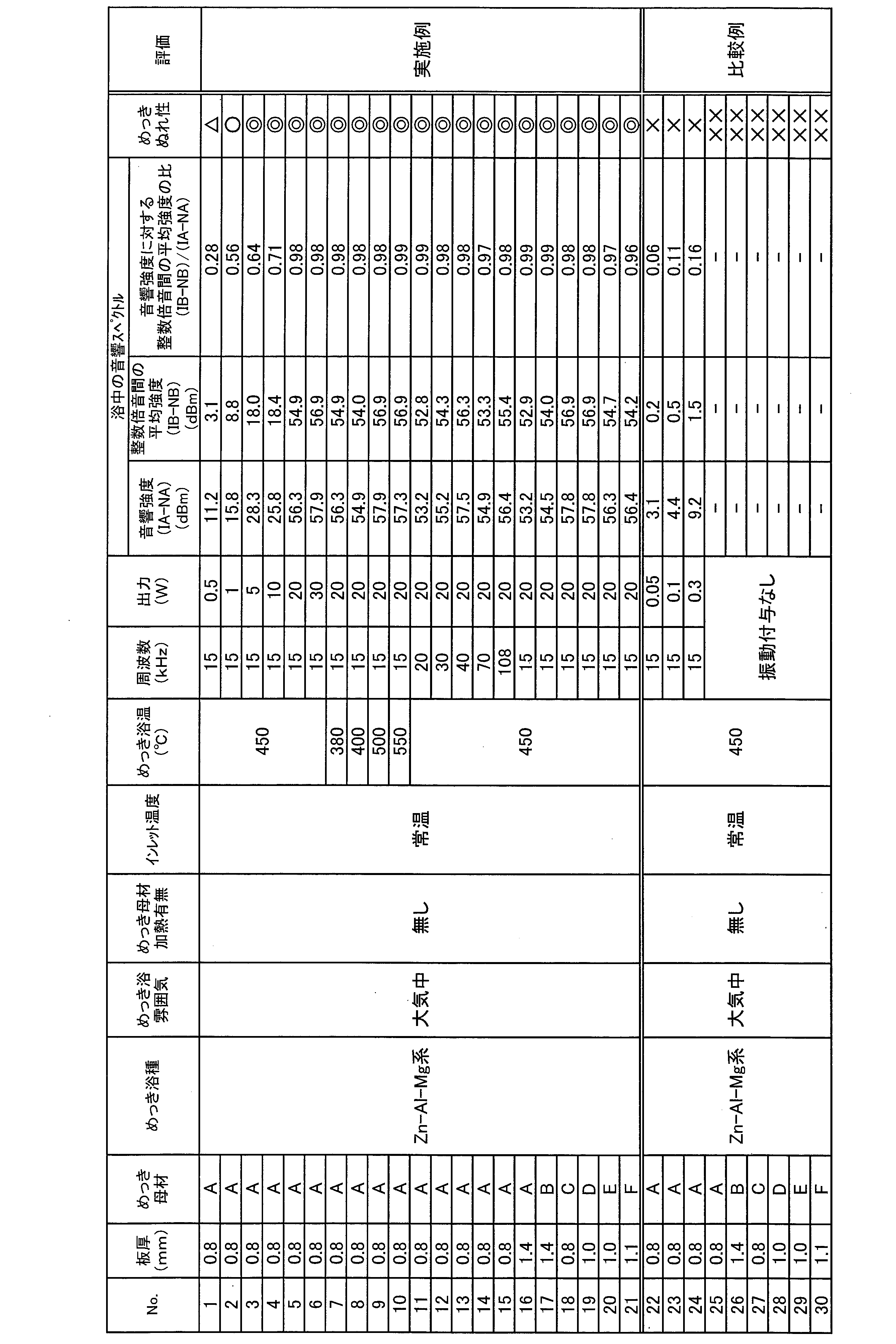
これに対し、溶融めっき浴中に付与した振動が弱すぎる(音圧が低すぎる)場合、溶融めっき浴中において本発明の範囲内の音響スペクトルが計測されず、表3のNo.22~24に示すように、めっき品の不めっき率は10%以上となった。また、溶融めっき浴中に振動を付与することなく溶融めっきを行った場合、表3のNo.25~30に示すように、めっき品の不めっき率は80%以上であった。
(例1-1-1:Zn-Al-Mg系の溶融めっき浴種を使用、めっき密着性)
表1に示した鋼板Aについて、酸洗処理によって種々の酸化膜の厚さに調整した後、どぶ漬けめっきを行った。このこと以外の条件は上記の例1-1と同様とした。どぶ漬けめっき後の試料を供試材として、上述のようにめっき密着性の評価を行った。試験の結果をまとめ、表4に示す。
表1に示した鋼板Aについて、酸洗処理によって種々の酸化膜の厚さに調整した後、どぶ漬けめっきを行った。このこと以外の条件は上記の例1-1と同様とした。どぶ漬けめっき後の試料を供試材として、上述のようにめっき密着性の評価を行った。試験の結果をまとめ、表4に示す。
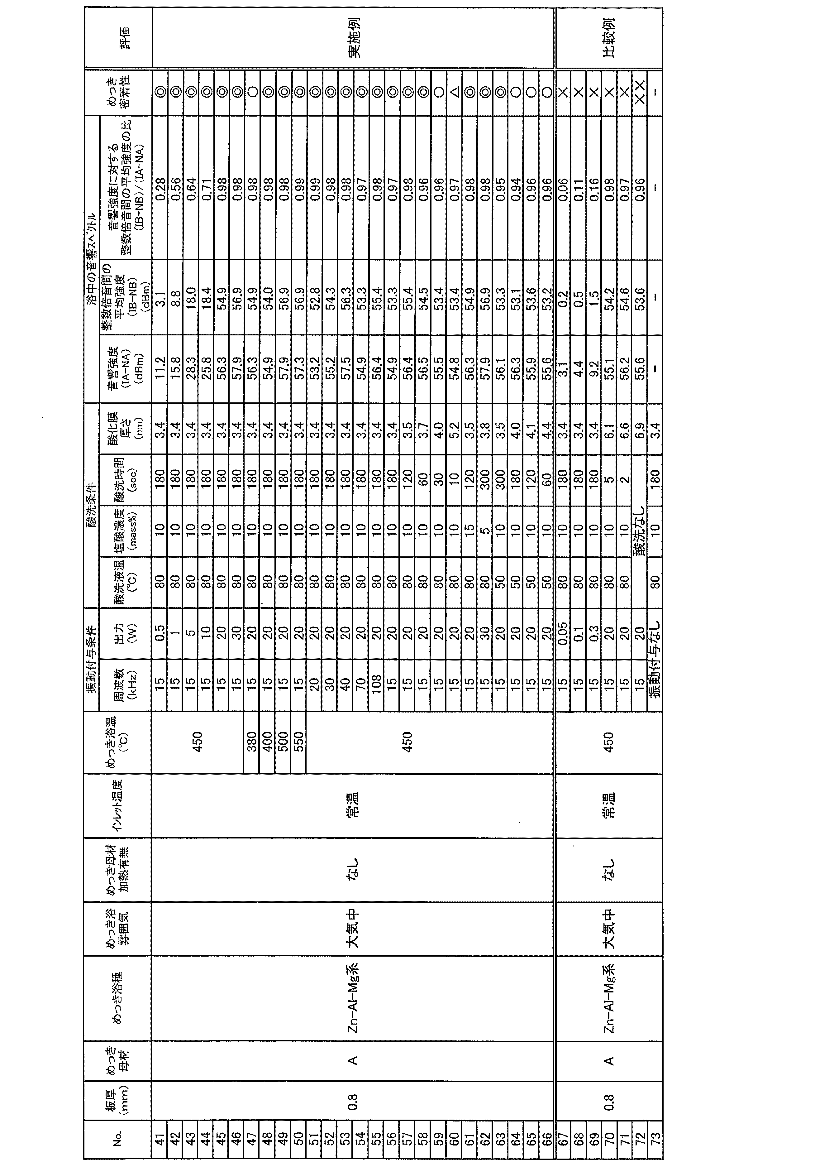
これに対し、溶融めっき浴中に付与した振動が弱すぎる(音圧が低すぎる)場合、酸化膜の厚さが本発明の範囲内であっても、溶融めっき浴中において本発明の範囲内の音響スペクトルが計測されず、表4のNo.67~69に示すように、めっき品に対してめっき密着性試験を行った結果のめっき剥離率が10%以上となった。また、酸化膜の厚さが本発明の範囲外の場合、溶融めっき浴中において本発明の範囲内の音響スペクトルが計測されるような条件にて溶融めっき浴中に振動を付与しつつ、鋼板にどぶ漬けめっきを施しても、表4のNo.70~72に示すように、めっき品に対してめっき密着性試験を行った結果のめっき剥離率が10%以上となった。また、溶融めっき浴中に振動を付与することなく溶融めっきを行った場合、表4のNo.73に示すように、めっき品にめっき層が十分に形成されず、めっき密着性について試験不可であった。
(例1-1-2:Zn-Al-Mg系の溶融めっき浴種を使用、めっき密着性、酸洗処理条件を変更)
表1に示した鋼板Aについて、塩酸以外の酸を用いて酸洗処理を行うことによって種々の酸化膜の厚さに調整した後、どぶ漬けめっきを行った。塩酸と硝酸との混合液として、塩酸(HCl)を7.5質量%、硝酸(HHO3)を2.5質量%、水(H2O)を90質量%の割合で混合した、いわゆる王水を用いた。このこと以外の条件は上記の例1-1と同様とした。どぶ漬けめっき後の試料を供試材として、上述のようにめっき密着性の評価を行った。試験の結果をまとめ、表5に示す。
表1に示した鋼板Aについて、塩酸以外の酸を用いて酸洗処理を行うことによって種々の酸化膜の厚さに調整した後、どぶ漬けめっきを行った。塩酸と硝酸との混合液として、塩酸(HCl)を7.5質量%、硝酸(HHO3)を2.5質量%、水(H2O)を90質量%の割合で混合した、いわゆる王水を用いた。このこと以外の条件は上記の例1-1と同様とした。どぶ漬けめっき後の試料を供試材として、上述のようにめっき密着性の評価を行った。試験の結果をまとめ、表5に示す。
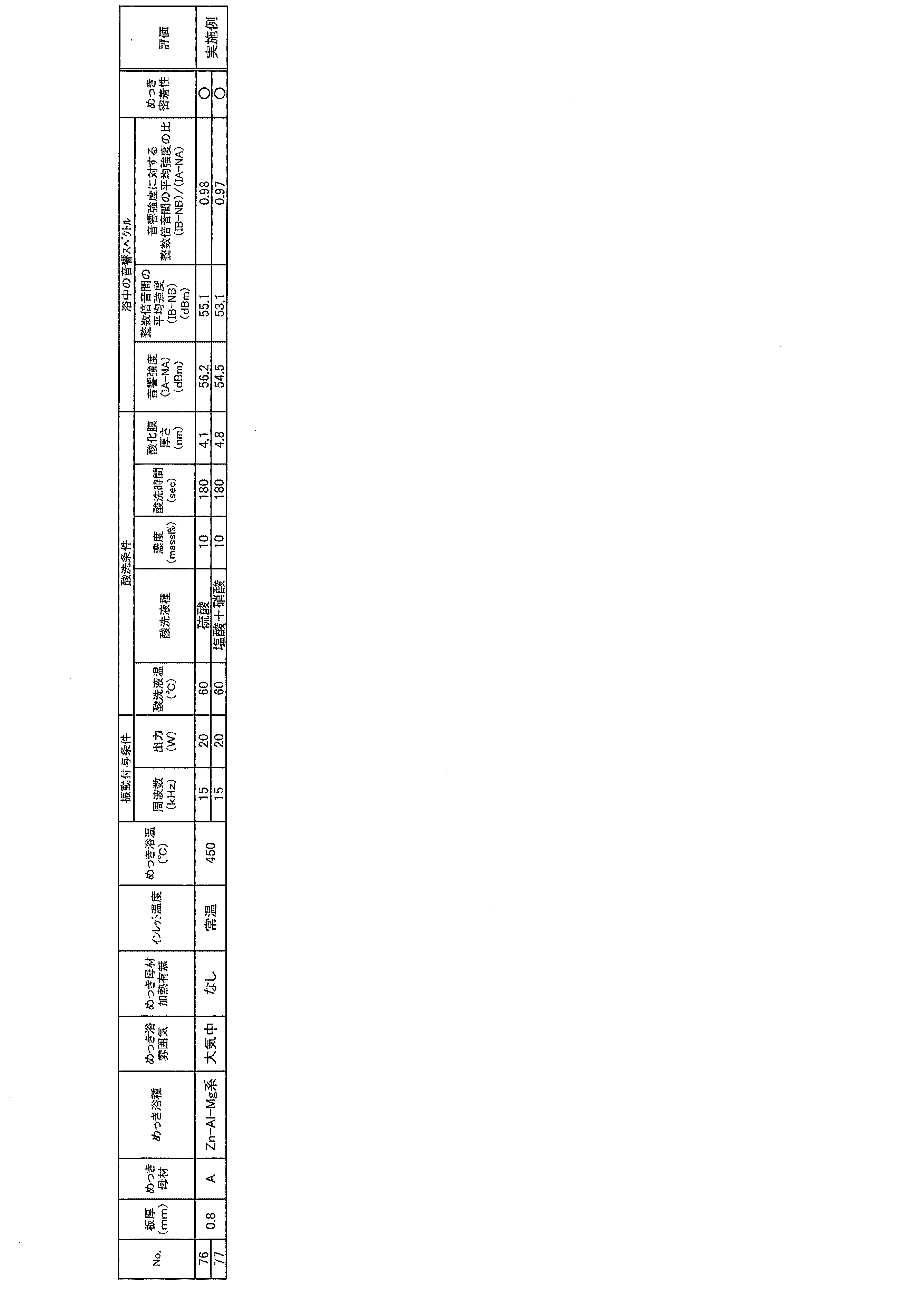
(例1-2:Al-Si系の溶融めっき浴種を使用、めっき濡れ性)
溶融めっき浴としてAl-9質量%Si-2質量%Fe系めっき浴を用いて、表1および表2に示した各種の鋼板にどぶ漬けめっきを行った。溶融めっき浴の温度は630℃~700℃、溶融めっき浴への鋼板の浸漬時間は12秒とし、鋼板を振動させる場合、鋼板を溶融めっき浴中へ浸漬開始してから10秒後に振動の付与を開始し、2秒間振動を付与した。鋼板を振動させる場合、基本周波数は15kHzとし、超音波振動子11の出力を10Wまたは0.05W~0.3Wに変化させた。これら以外の条件は上記の例1-1と同様とした。試験の結果をまとめ、表6に示す。
溶融めっき浴としてAl-9質量%Si-2質量%Fe系めっき浴を用いて、表1および表2に示した各種の鋼板にどぶ漬けめっきを行った。溶融めっき浴の温度は630℃~700℃、溶融めっき浴への鋼板の浸漬時間は12秒とし、鋼板を振動させる場合、鋼板を溶融めっき浴中へ浸漬開始してから10秒後に振動の付与を開始し、2秒間振動を付与した。鋼板を振動させる場合、基本周波数は15kHzとし、超音波振動子11の出力を10Wまたは0.05W~0.3Wに変化させた。これら以外の条件は上記の例1-1と同様とした。試験の結果をまとめ、表6に示す。
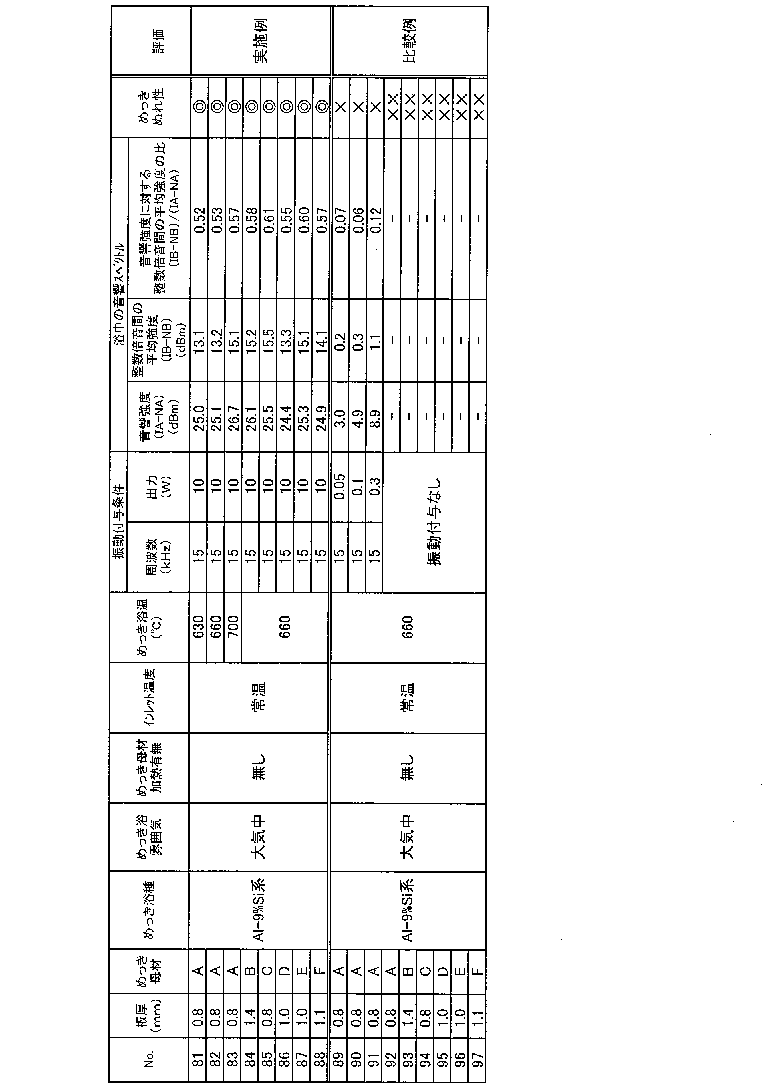
これに対し、溶融めっき浴中に付与した振動が弱すぎる(音圧が低すぎる)場合、溶融めっき浴中において本発明の範囲内の音響スペクトルが計測されず、表6のNo.89~91に示すように、めっき品の不めっき率は10%以上となった。また、溶融めっき浴中に振動を付与することなく溶融めっきを行った場合、表6のNo.92~97に示すように、めっき品の不めっき率は80%以上であった。
(例1-3:各種の溶融めっき浴種を使用、めっき濡れ性)
溶融めっき浴として、実施形態3の実施例2(例2-3)に示す各種の溶融めっき浴を用いて、表1および表2に示した各種の鋼板A~Fにどぶ漬けめっきを行った。溶融めっき浴M1~M10の組成は実施例2の表11に示され、溶融めっき浴M12の組成は実施例2の表12に示されている。また、めっき浴種M11は、Al-2質量%Fe系めっき浴であり、浴温は700℃である(めっき浴種M11は、表6に示す試験にて用いたAl-9質量%Si-2質量%Fe系めっき浴と異なり、Siを添加していない)。
溶融めっき浴として、実施形態3の実施例2(例2-3)に示す各種の溶融めっき浴を用いて、表1および表2に示した各種の鋼板A~Fにどぶ漬けめっきを行った。溶融めっき浴M1~M10の組成は実施例2の表11に示され、溶融めっき浴M12の組成は実施例2の表12に示されている。また、めっき浴種M11は、Al-2質量%Fe系めっき浴であり、浴温は700℃である(めっき浴種M11は、表6に示す試験にて用いたAl-9質量%Si-2質量%Fe系めっき浴と異なり、Siを添加していない)。
溶融めっき浴への鋼板の浸漬時間は12秒とし、鋼板を振動させる場合、鋼板を溶融めっき浴中へ浸漬開始してから10秒後に振動の付与を開始し、2秒間振動を付与した。
例1-3における実施例においては、基本周波数を15kHz、超音波振動子11の出力を20Wと、それぞれ一定にして、溶融めっき浴中へ振動を付与した。比較例では、溶融めっき浴中へ振動を付与することなく、どぶ漬けめっきを行った。また、実施例および比較例において、鋼板A~Fとしては、板厚が0.8mmのものを用いた。
上記以外の条件は上記の例1-1と同様とした。試験の結果をまとめ、表7に示す。

これに対し、溶融めっき浴中に振動を付与することなく溶融めっきを行った場合、表7のNo.173~184に示すように、めっき品の不めっき率は80%以上であった。
(例1-3’:各種の溶融めっき浴種を使用、めっき密着性)
表1に示した鋼板Aについて、塩酸を用いて酸洗処理を行うことによって酸化膜の厚さを低減した後、溶融めっき浴として、実施形態3の実施例2(例2-3)に示す各種の溶融めっき浴を用いて、どぶ漬けめっきを行った。溶融めっき浴M1~M10の組成は実施例2の表11に示されている。
表1に示した鋼板Aについて、塩酸を用いて酸洗処理を行うことによって酸化膜の厚さを低減した後、溶融めっき浴として、実施形態3の実施例2(例2-3)に示す各種の溶融めっき浴を用いて、どぶ漬けめっきを行った。溶融めっき浴M1~M10の組成は実施例2の表11に示されている。
例1-3における実施例においては、基本周波数を15kHz、超音波振動子11の出力を20Wと、それぞれ一定にして、溶融めっき浴中へ振動を付与した。比較例では、溶融めっき浴中へ振動を付与することなく、どぶ漬けめっきを行った。また、実施例および比較例において、鋼板Aとしては、板厚が0.8mmのものを用いた。
上記以外の条件は上記の例1-1と同様とした。試験の結果をまとめ、表8に示す。

これに対し、酸化膜の厚さが本発明の範囲外の場合、溶融めっき浴中において本発明の範囲内の音響スペクトルが計測されるような条件にて溶融めっき浴中に振動を付与しつつ、鋼板にどぶ漬けめっきを施しても、表8のNo.201~210に示すように、めっき品に対してめっき密着性試験を行った結果のめっき剥離率が80%以上となった。また、溶融めっき浴中に振動を付与することなく溶融めっきを行った場合、表8のNo.211~220に示すように、めっき品にめっき層が十分に形成されず、めっき密着性について試験不可であった。
〔実施形態2〕
本発明の他の実施形態について、以下に説明する。なお、説明の便宜上、上記実施形態にて説明した部材と同じ機能を有する部材については、同じ符号を付記し、その説明を繰り返さない。
本発明の他の実施形態について、以下に説明する。なお、説明の便宜上、上記実施形態にて説明した部材と同じ機能を有する部材については、同じ符号を付記し、その説明を繰り返さない。
前記実施形態1における溶融めっき装置1(図1参照)では、溶融めっき浴20内における導波棒31の先端と鋼板2の表面との距離L1を10mmに固定して、音響スペクトルを測定した。本発明者の更なる検討によれば、音響スペクトルを測定する位置の変化に伴って、音響スペクトルにおける上記特徴的強度比は変化し得ることがわかった。
そこで、上記距離L1を1mm~80mmと変化させるとともに、超音波振動子11の出力を0.1W~20Wに変化させて音響スペクトルを測定した。その結果を図7の(a)~(e)に示す。図7の(a)~(e)は、各距離L1において超音波振動子11の出力を変化させて測定した音響スペクトルを示すグラフであり、(a)は距離L1が1mm、(b)は距離L1が5mm、(c)は距離L1が10mm、(d)は距離L1が30mm、(e)は距離L1が80mmの場合をそれぞれ示している。
図8は、上記距離L1と上記特徴的強度比との関係を示すグラフである。図8に示すように、距離L1が遠くなるほど、特徴的強度比は低下する傾向にあり、特に、出力の弱い(具体的には0.1W、0.5W)場合にはその傾向が顕著である。このことから、例えば出力が0.1Wまたは0.5Wの場合、音響スペクトルを検知するためには、距離L1を10mm以下とすることが好ましいといえる。
また、図7の(a)~(e)に示すように、距離L1が大きすぎると、音響スペクトルの信号強度が小さくなり、ノイズレベルを下回ることにより信号を検出し難いことがある。そのため、溶融めっき浴20内の振動状態を正確に評価し難いことがある。よって、本溶融めっき方法では、出力が0.5W以上であるとともに、距離L1は10mm以下であることが好ましい。
〔実施形態3〕
本発明の他の実施形態について、以下に説明する。なお、説明の便宜上、上記実施形態にて説明した部材と同じ機能を有する部材については、同じ符号を付記し、その説明を繰り返さない。
本発明の他の実施形態について、以下に説明する。なお、説明の便宜上、上記実施形態にて説明した部材と同じ機能を有する部材については、同じ符号を付記し、その説明を繰り返さない。
前記実施形態1および実施形態2では、超音波ホーン10の先端に鋼板2を取り付けた状態において、超音波ホーン10を用いて鋼板2に振動を付与していた。これに対して、本実施形態では、超音波ホーン10の先端に振動板を取り付けた状態において、超音波ホーン10を用いて振動板に振動を付与し、溶融めっき浴20を介して、鋼板2に間接的に振動を与える点が異なっている。
(溶融めっき装置)
本実施形態における溶融めっき方法を実施する溶融めっき装置60について、図9を用いて説明する。なお、溶融めっき装置60は一例であって、本溶融めっき方法を実施する装置は、特に限定されるものではない。図9は、本実施の形態における溶融めっき方法を実施する溶融めっき装置60を示す概略図である。
本実施形態における溶融めっき方法を実施する溶融めっき装置60について、図9を用いて説明する。なお、溶融めっき装置60は一例であって、本溶融めっき方法を実施する装置は、特に限定されるものではない。図9は、本実施の形態における溶融めっき方法を実施する溶融めっき装置60を示す概略図である。
図9に示すように、溶融めっき装置60は、ガス還元加熱帯61と、溶融めっき部62と、超音波ホーン10と、音響スペクトルを測定する測定装置50と、を備えている。ガス還元加熱帯61は、雰囲気ガス導入部61aおよび加熱部61bを備え、鋼板2に対して所望の雰囲気にて加熱処理を行うことが可能となっている。
溶融めっき部62では、ルツボ炉41の上方の空間が、ポートフランジ64およびOリング65によって大気から遮断されている。また、ポートフランジ64の一部には雰囲気ガス導入部66が設けられており、溶融めっき部62における雰囲気を制御することができるようになっている。
ガス還元加熱帯61と溶融めっき部62との間にはゲートバルブ63が設けられている。ガス還元加熱帯61にて処理された鋼板2は、ゲートバルブ63を開いて、大気に晒されることなく溶融めっき部62に移送される。鋼板2は、ゲートバルブ63よりも上のガス還元加熱帯61において、雰囲気制御および加熱処理といった前処理を受けたのちに、めっき浴21の中に進入する。
また、本実施形態の溶融めっき装置60では、超音波ホーン10の先端に鋼板2ではなく振動板70が固定されている。この振動板70は、ここでは、材質が普通鋼(表1の鋼板Aと同じ鋼種)であって、長さ150mm×幅50mm×厚さ0.8mmの板を用いた。振動板70の振動によって、溶融めっき浴金属21に振動を付与する。これにより、溶融めっき浴金属21を介して、鋼板2に振動が与えられる。すなわち、溶融めっき装置60は、鋼板2に間接的に振動を付与するようになっている。なお、振動板70としては、上記の材質に限定されない。振動板70は、溶融めっき浴中に浸漬された場合に耐侵食性が強く、溶融めっき浴に対する濡れ性が良くない材質のものが好ましく、例えばセラミックスを用いることができる。
その他の測定装置50等の構成は、前述の溶融めっき装置40(図5参照)と同様であるため、詳しい説明を省略する。
上記のような溶融めっき装置60は、連続式溶融めっき方法へと適用することが可能である。つまり、連続式溶融めっき方法では、鋼板に直接的に振動を付与することは難しいが、溶融めっき装置60のように鋼板2に間接的に振動を付与することができる。よって、上記のような溶融めっき装置60を用いて実証された結果は、連続式溶融めっき方法に適用することができる。連続式溶融めっき方法への適用例について、具体的には後述する。
〔実施例2〕
本発明の実施形態3における溶融めっき方法の実施例について以下に説明する。本実施例では、上述の図9に示す溶融めっき装置60を用いた。
本発明の実施形態3における溶融めっき方法の実施例について以下に説明する。本実施例では、上述の図9に示す溶融めっき装置60を用いた。
前記実施例1と同様に各種の鋼板A~F(表1および表2参照)を用いるとともに、Zn-Al-Mg系の溶融めっき浴またはAl-9質量%Si-2質量%Fe系めっき浴を用いて、各種の条件にて溶融めっきを行った。
(例2-1:ガス還元加熱帯61における加熱処理無し)
各種の鋼板にはそれぞれ前処理としてアルカリ脱脂処理を行った。溶融めっき浴として、前述の実施例1の例1-1におけるZn-Al-Mg系めっき浴、および実施例1の例1-2におけるAl-9%Si系めっき浴を用いた。溶融めっき部62における雰囲気を大気雰囲気、窒素雰囲気、3%水素-窒素雰囲気、または30%水素-窒素雰囲気に変化させた。ガス還元加熱帯61における雰囲気制御および加熱処理は行わなかった。溶融めっき浴への鋼板の浸漬時間は12秒とし、超音波ホーン10を用いて振動板70を振動させて溶融めっき浴中へ振動を付与する場合、鋼板を溶融めっき浴中へ浸漬開始してから10秒後に振動の付与を開始し、2秒間振動を付与した。振動板70を振動させる場合、基本周波数を15kHz、超音波振動子11の出力を30Wと、それぞれ一定にして、溶融めっき浴中へ振動を付与した。
各種の鋼板にはそれぞれ前処理としてアルカリ脱脂処理を行った。溶融めっき浴として、前述の実施例1の例1-1におけるZn-Al-Mg系めっき浴、および実施例1の例1-2におけるAl-9%Si系めっき浴を用いた。溶融めっき部62における雰囲気を大気雰囲気、窒素雰囲気、3%水素-窒素雰囲気、または30%水素-窒素雰囲気に変化させた。ガス還元加熱帯61における雰囲気制御および加熱処理は行わなかった。溶融めっき浴への鋼板の浸漬時間は12秒とし、超音波ホーン10を用いて振動板70を振動させて溶融めっき浴中へ振動を付与する場合、鋼板を溶融めっき浴中へ浸漬開始してから10秒後に振動の付与を開始し、2秒間振動を付与した。振動板70を振動させる場合、基本周波数を15kHz、超音波振動子11の出力を30Wと、それぞれ一定にして、溶融めっき浴中へ振動を付与した。
振動板と鋼板との距離(間隔)が5mmとなるように、溶融めっき浴中における鋼板および振動板の配置を調整した。鋼板と導波棒の先端との互いの距離は5mmとした。
また、比較例として、溶融めっき浴中へ振動を付与することなく、溶融めっき装置60を用いて鋼板にどぶ漬けめっきを行った。試験の結果をまとめ、表9に示す。

これに対し、溶融めっき浴中に振動を付与することなく溶融めっきを行った場合、表9のNo.489~504に示すように、各種いずれの条件においてもめっき品の不めっき率は80%以上であった。
(例2-2:ガス還元加熱帯61における加熱処理有り)
ガス還元加熱帯61における雰囲気制御および加熱処理を行うとともに、鋼板を溶融めっき浴中へ浸漬開始してから2秒後に振動の付与を開始し、2秒間振動を付与したこと以外は上記の例2-1と同様にして、溶融めっきを行った。試験の結果をまとめ、表10に示す。
ガス還元加熱帯61における雰囲気制御および加熱処理を行うとともに、鋼板を溶融めっき浴中へ浸漬開始してから2秒後に振動の付与を開始し、2秒間振動を付与したこと以外は上記の例2-1と同様にして、溶融めっきを行った。試験の結果をまとめ、表10に示す。
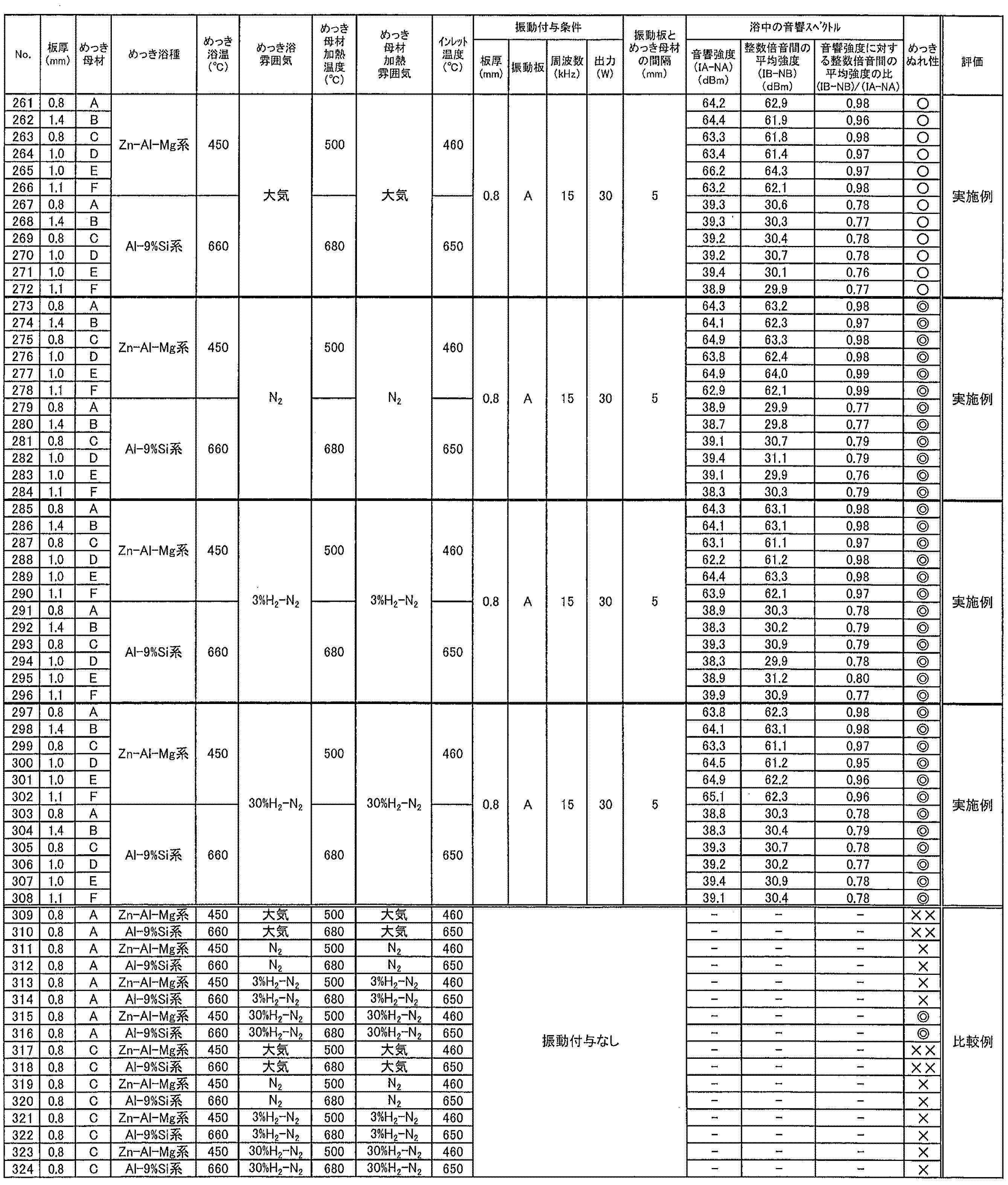
また、表10のNo.273~308に示すように、ガス還元加熱帯61における加熱雰囲気および溶融めっき浴の雰囲気を非酸化性雰囲気とした場合、鋼板を加熱した状態にて鋼板を溶融めっき浴に進入させても、溶融めっき浴中において本発明の範囲内の音響スペクトルが計測されるような条件にて振動を付与していることによって、めっき品の不めっき率は0%となった。
これに対し、大気雰囲気にて鋼板を加熱した後、溶融めっき浴中に振動を付与することなく溶融めっきを行った場合、表10のNo.309、310、317、318に示すように、めっき品の不めっき率は80%以上であった。
また、表10のNo.311~314、319~324に示すように、ガス還元加熱帯61における加熱雰囲気および溶融めっき浴の雰囲気を非酸化性雰囲気として、溶融めっき浴中に振動を付与することなく溶融めっきを行った場合、めっき品の不めっき率は10%以上80%未満となった。
なお、従来技術と同様に、鋼板に還元加熱処理を行って、還元雰囲気下で溶融めっきを行った場合、表10のNo.315、316に示すように、めっき品の不めっき率は0%であった。
(例2-3:ガス還元加熱帯61における加熱処理無し・各種のめっき浴使用)
下記表11、表12に示す組成の溶融めっき浴を用い、溶融めっき部62における雰囲気を3%水素-窒素雰囲気としたこと以外は上記の例2-1と同様にして、溶融めっきを行った。めっき浴種M11は、Al-2質量%Fe系めっき浴、浴温は700℃である(めっき浴種M11は、表6に示す試験にて用いたAl-9質量%Si-2質量%Fe系めっき浴と異なり、Siを添加していない)。試験の結果をまとめ、表13に示す。
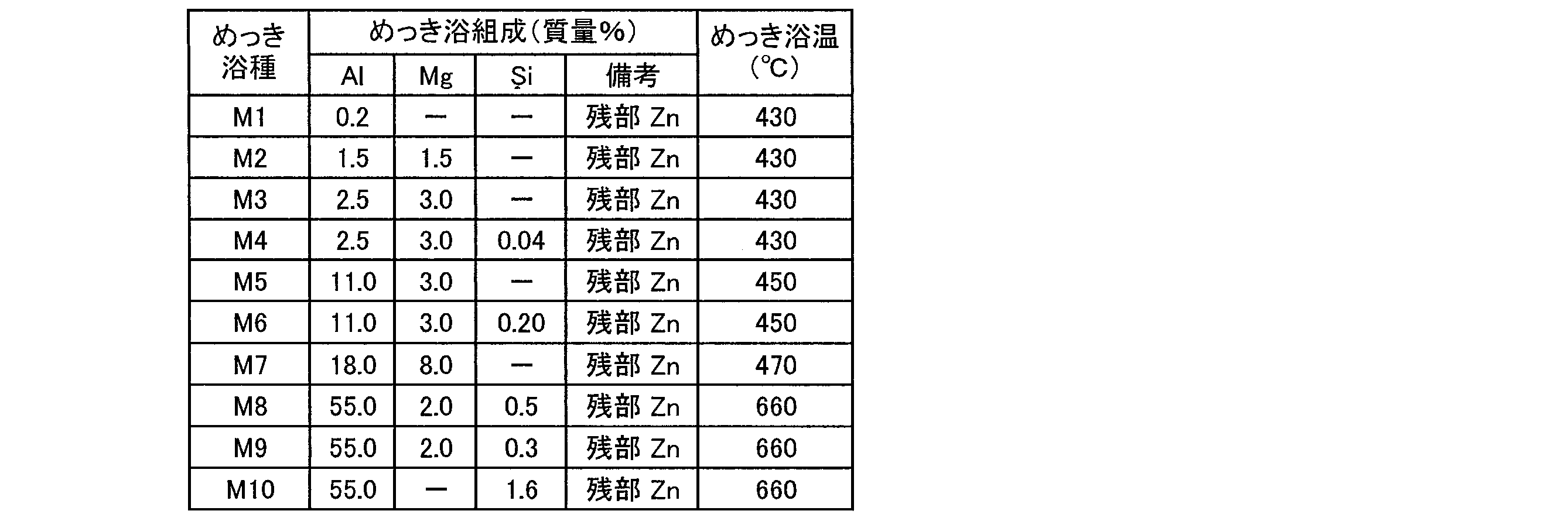

下記表11、表12に示す組成の溶融めっき浴を用い、溶融めっき部62における雰囲気を3%水素-窒素雰囲気としたこと以外は上記の例2-1と同様にして、溶融めっきを行った。めっき浴種M11は、Al-2質量%Fe系めっき浴、浴温は700℃である(めっき浴種M11は、表6に示す試験にて用いたAl-9質量%Si-2質量%Fe系めっき浴と異なり、Siを添加していない)。試験の結果をまとめ、表13に示す。
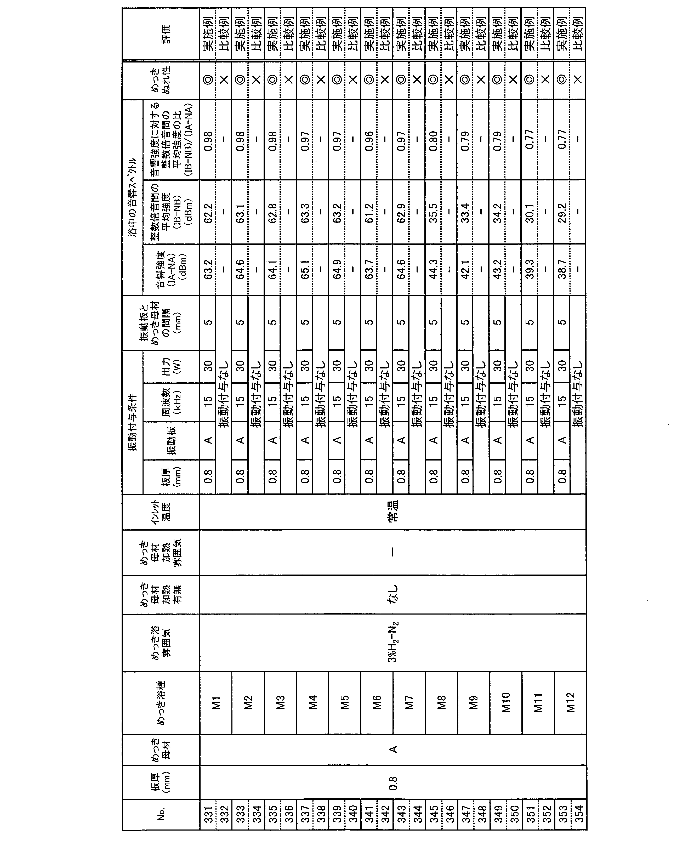
これに対し、溶融めっき浴中に振動を付与することなく溶融めっきを行った場合、表13のNo.332、334、336、338、340、342、344、346、348、350、352、354に示すように、めっき品の不めっき率は10%以上であった。
〔実施形態4〕
本発明の溶融めっき方法により製造された溶融めっき鋼板は、めっき層の表面に、耐食性および皮膜密着性を向上させる下地化成処理皮膜が形成されていてもよい。下地化成処理皮膜としては、無機系皮膜が好ましく、さらに具体的には、バルブメタルの酸化物または水酸化物と、バルブメタルのフッ化物とを含有するものが好ましい。ここで「バルブメタル」とは、その酸化物が高い絶縁抵抗を示す金属をいう。バルブメタル元素としては、Ti、Zr、Hf、V、Nb、Ta、MoおよびWから選ばれる1種または2種以上の元素が好ましい。また、下地化成処理皮膜は、可溶性または難溶性の金属リン酸塩または複合リン酸塩を含んでいてもよい。さらに、下地化成処理皮膜は、フッ素系、ポリエチレン系、スチレン系などの有機ワックス、または、シリカ、二硫化モリブデン、タルクなどの無機質潤滑剤などを含んでいてもよい。下地化成処理皮膜は、ウレタン樹脂、アクリル樹脂、エポキシ樹脂、オレフィン樹脂、ポリステル樹脂などをベースとする有機系皮膜であってもよい。
本発明の溶融めっき方法により製造された溶融めっき鋼板は、めっき層の表面に、耐食性および皮膜密着性を向上させる下地化成処理皮膜が形成されていてもよい。下地化成処理皮膜としては、無機系皮膜が好ましく、さらに具体的には、バルブメタルの酸化物または水酸化物と、バルブメタルのフッ化物とを含有するものが好ましい。ここで「バルブメタル」とは、その酸化物が高い絶縁抵抗を示す金属をいう。バルブメタル元素としては、Ti、Zr、Hf、V、Nb、Ta、MoおよびWから選ばれる1種または2種以上の元素が好ましい。また、下地化成処理皮膜は、可溶性または難溶性の金属リン酸塩または複合リン酸塩を含んでいてもよい。さらに、下地化成処理皮膜は、フッ素系、ポリエチレン系、スチレン系などの有機ワックス、または、シリカ、二硫化モリブデン、タルクなどの無機質潤滑剤などを含んでいてもよい。下地化成処理皮膜は、ウレタン樹脂、アクリル樹脂、エポキシ樹脂、オレフィン樹脂、ポリステル樹脂などをベースとする有機系皮膜であってもよい。
また、本発明の溶融めっき方法により製造された溶融めっき鋼板は、めっき層の表面に、ポリエステル系、アクリル樹脂系、フッ素樹脂系、塩化ビニル樹脂系、ウレタン樹脂系、エポキシ樹脂系等の樹脂系塗料を、ロール塗装、スプレー塗装、カーテンフロー塗装、ディップ塗装等の方法により塗装することができる。あるいはアクリル樹脂フィルム等のプラスチックフィルムを積層する際のフィルムラミネートの基材として用いることもできる。
〔実施形態5〕
本発明の他の実施形態について、以下に説明する。なお、説明の便宜上、上記実施形態にて説明した部材と同じ機能を有する部材については、同じ符号を付記し、その説明を繰り返さない。
本発明の他の実施形態について、以下に説明する。なお、説明の便宜上、上記実施形態にて説明した部材と同じ機能を有する部材については、同じ符号を付記し、その説明を繰り返さない。
本実施形態における溶融めっき方法では、超音波ホーンの一部を溶融めっき浴中に浸漬させて、超音波ホーンの先端から溶融めっき浴に振動を付与する。これにより、超音波ホーンの先端から、溶融めっき浴を介して間接的に鋼板へ振動を伝達させて、鋼板にどぶ漬けめっきを施す。
(溶融めっき装置)
本実施形態における溶融めっき方法を実施する溶融めっき装置80について、図10を用いて説明する。なお、溶融めっき装置80は一例であって、本溶融めっき方法を実施する装置は、特に限定されるものではない。図10は、本実施の形態における溶融めっき方法を実施する溶融めっき装置80を示す概略図である。
本実施形態における溶融めっき方法を実施する溶融めっき装置80について、図10を用いて説明する。なお、溶融めっき装置80は一例であって、本溶融めっき方法を実施する装置は、特に限定されるものではない。図10は、本実施の形態における溶融めっき方法を実施する溶融めっき装置80を示す概略図である。
図10に示すように、溶融めっき装置80は、昇降装置81と、超音波ホーン10Aと、音響スペクトルを測定する測定装置50と、溶融めっき浴金属21が貯留されたカーボンルツボ42と、を備えている。溶融めっき装置80では、大気中で、かつ、鋼板2を加熱することなく、鋼板2が溶融めっき浴20中に浸漬される。
昇降装置81は、鋼板2を保持した状態にて、鋼板2を溶融めっき浴20中に浸漬させること、および、鋼板2を溶融めっき浴20から引き上げることを可能とする装置である。昇降装置81としては、公知の装置を用いればよく、詳細な説明は省略する。
超音波ホーン10Aは、超音波振動子11と、先端部17と、超音波振動子11および先端部17を接続する接続部16と、を備えている。超音波振動子11は、振動子固定ステージ19によって固定されている。接続部16は、超音波振動子11にて発生した振動の周波数に対応して共振し易い長さを有している。接続部16は、単なるアダプタであってもよく、超音波振動子11にて発生した振幅を増幅して先端部17に伝達するブースターであってもよい。
超音波ホーン10Aにおける先端部17の少なくとも一部が溶融めっき浴20に浸漬された状態で、超音波振動子11が、超音波電源装置D1から送信された超音波信号を受信して超音波振動する。この超音波振動が接続部16を介して先端部17に伝達し、先端部17によって溶融めっき浴20中に振動が付与される。
昇降装置81によって鋼板2を溶融めっき浴20中に浸漬させる場合、先端部17の前面に鋼板2が配置される。先端部17の、長手方向における接続部16から遠い方の端部には、当該端部の断面形状が二等辺三角形状となるように振動面17Aが形成されており、振動面17Aは、溶融めっき浴20中に浸漬された鋼板2の表面と対向する。
先端部17は、セラミック製であることが好ましい。これは、溶融めっき浴20中において先端部17が超音波振動することによって発生し得る先端部17の劣化を低減するためである。
なお、溶融めっき装置80は、超音波ホーン10Aの代わりに、一体型である超音波ホーンを用いてもよい。この場合、超音波ホーンの先端部をセラミックス製とすればよい。
先端部17の振動面17Aと鋼板2の表面との距離L2は、0mmであってもよく、0mmより大きく50mm以下であってもよい。距離L2が0mmとは、超音波ホーン10Aが超音波振動する前の時点(すなわちセッティングの時点)において、振動面17Aと鋼板2の表面とが互いに接していることを意味する。例えば昇降装置81が鋼板2を水平方向に移動させることが可能となっており、距離L2は、昇降装置81を用いて鋼板2を水平方向に移動させることにより調整することができる。距離L2は、好ましくは0mmより大きく5mm以下である。
溶融めっき装置80において、超音波ホーン10Aを用いて溶融めっき浴20中に付与される振動の周波数、出力等については、前記実施形態1にて説明したことと同様である。
〔実施例3〕
本発明の実施形態5における溶融めっき方法の実施例について以下に説明する。本実施例では、上述の図10に示す溶融めっき装置80を用いた。
本発明の実施形態5における溶融めっき方法の実施例について以下に説明する。本実施例では、上述の図10に示す溶融めっき装置80を用いた。
本実施例における溶融めっき装置80に用いた各種機器は、具体的には以下のとおりである。
(超音波振動供給系統)
・超音波振動子11:hielscher社製、20kHz振動子
・接続部16(ブースター):材質<Ti>、増幅率2.2倍、1/2波長型、長さ126mm
・先端部17:材質<Ti>、1/2波長型、長さ250mm
・超音波電源装置D1:hielscher社製、20kHz、2kW電源
(超音波振動測定系統)
・導波棒51:材質<SUS430>、φ6mm×300mm
・AEセンサ52:(株)エヌエフ回路設計ブロック社製、AE-900M
・計測部53
アンプ:(株)エヌエフ回路設計ブロック社製、AE9922
スペクトラムアナライザ:アジレント・テクノロジー(株)社製、E4408B。
・超音波振動子11:hielscher社製、20kHz振動子
・接続部16(ブースター):材質<Ti>、増幅率2.2倍、1/2波長型、長さ126mm
・先端部17:材質<Ti>、1/2波長型、長さ250mm
・超音波電源装置D1:hielscher社製、20kHz、2kW電源
(超音波振動測定系統)
・導波棒51:材質<SUS430>、φ6mm×300mm
・AEセンサ52:(株)エヌエフ回路設計ブロック社製、AE-900M
・計測部53
アンプ:(株)エヌエフ回路設計ブロック社製、AE9922
スペクトラムアナライザ:アジレント・テクノロジー(株)社製、E4408B。
前記実施例1の例1-1’と同様に、表1に示した鋼板Aについて、酸洗処理によって種々の酸化膜の厚さに調整した後、Zn-Al-Mg系の溶融めっき浴を用いて、各種の条件にてどぶ漬けめっきを行った。
超音波ホーン10Aを用いて溶融めっき浴中へ振動を付与する場合、距離L2は0mm~50mmとし、基本周波数は20kHzまたは50kHzとした。
超音波ホーン10Aを用いて溶融めっき浴中へ振動を付与する場合、鋼板2を溶融めっき浴中へ浸漬開始してから10秒後に振動の付与を開始し、2秒間~60秒間振動を付与した。
超音波振動子11には、超音波振動子11の振幅をモニタするための振幅センサが内蔵されている。表示装置を用いて、上記振幅センサからの出力を受信し、フルスケールを5Vとして当該出力を表示させた。表示装置によって表示された出力には超音波振動子11の振幅の大小が反映されることから、以下では、フルスケールの5Vを出力100%とし、超音波振動子11の振幅の大小を表す指標として「出力%」を用いた。
ここで、鋼板を直接振動させる方法(直接法)では、超音波電源にとっての負荷は鋼板そのものと考えられる。一方で、溶融めっき浴を介して間接的に鋼板を振動させる方法(間接法)の場合、超音波電源にとっての負荷は、鋼板および溶融めっき浴となる。そのため、超音波電源からの出力(W)そのものではなく、共振しているときの超音波振動子の振幅を表す指標となる「出力%」を用いて、振動付与条件を表している。
また、比較例として、溶融めっき浴中へ振動を付与することなく、溶融めっき装置80を用いて各供試材にどぶ漬けめっきを行った。試験の結果をまとめ、表14に示す。
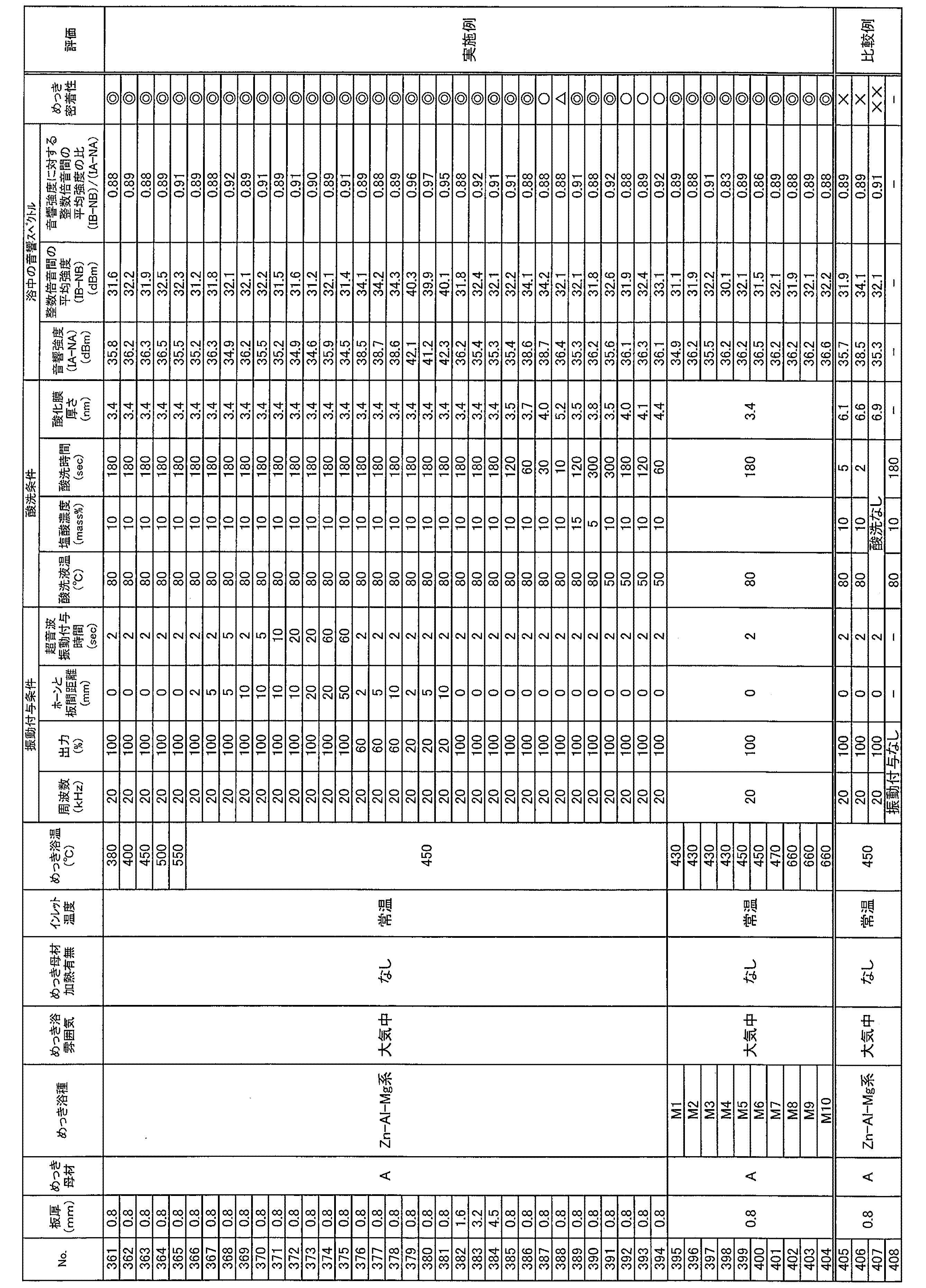
これに対し、酸化膜の厚さが本発明の範囲外の場合、溶融めっき浴中において本発明の範囲内の音響スペクトルが計測されるような条件にて溶融めっき浴中に振動を付与しつつ、鋼板にどぶ漬けめっきを施しても、表14のNo.405、406に示すように、めっき品に対してめっき密着性試験を行った結果のめっき剥離率が10%以上となった。また、溶融めっき浴中に振動を付与することなく溶融めっきを行った場合、表14のNo.408に示すように、めっき品にめっき層が十分に形成されず、めっき密着性について試験不可であった。
〔実施形態6〕
本発明の他の実施形態について、以下に説明する。なお、説明の便宜上、上記実施形態にて説明した部材と同じ機能を有する部材については、同じ符号を付記し、その説明を繰り返さない。
本発明の他の実施形態について、以下に説明する。なお、説明の便宜上、上記実施形態にて説明した部材と同じ機能を有する部材については、同じ符号を付記し、その説明を繰り返さない。
本実施形態における溶融めっき方法では、鋼帯を溶融めっき浴中に連続的に通板させる連続式溶融めっき設備を用いるとともに、超音波ホーンの一部を溶融めっき浴中に浸漬させて鋼帯の近傍に超音波ホーンの先端を配置する。超音波ホーンの先端から溶融めっき浴または鋼帯に振動を付与しつつ、鋼帯に対して連続的に溶融めっきを施す。
(溶融めっき設備)
本実施形態における溶融めっき方法を実施する溶融めっき設備90Aについて、図11を用いて説明する。なお、溶融めっき装置90Aは一例であって、本溶融めっき方法を実施する装置は、特に限定されるものではない。図11は、本実施の形態における溶融めっき方法を実施する溶融めっき設備90Aの一例を示す概略図である。
本実施形態における溶融めっき方法を実施する溶融めっき設備90Aについて、図11を用いて説明する。なお、溶融めっき装置90Aは一例であって、本溶融めっき方法を実施する装置は、特に限定されるものではない。図11は、本実施の形態における溶融めっき方法を実施する溶融めっき設備90Aの一例を示す概略図である。
図11に示すように、溶融めっき設備90Aは、一般的な連続式溶融めっき設備に超音波ホーン10Bおよび測定装置50を加えた構成である。鋼帯2Aは、スナウト91を通じて溶融めっき浴20に浸漬される。鋼帯2Aは、ガイドロール92およびサポートロール93によって、溶融めっき浴20中を通板した後、引き上げられて、ガス吹付け等によりめっき付着量を調整される。
鋼帯2Aには、めっき工程の前処理として、酸洗処理等によって、鋼帯2A表面の鉄酸化物層の除去が行われていてもよい。また、溶融めっき設備90Aは、スナウト91の前段に設けられた図示しない加熱装置によって、鋼帯2Aを溶融めっきに適した温度に加熱するようになっていてもよい。
ここで、溶融めっき設備90Aは、一般的な連続式溶融めっき設備とは異なり、スナウト91の前段に還元加熱装置は設けられていなくてもよい。溶融めっき設備90Aでは、超音波ホーン10Bを用いて溶融めっき浴20中に超音波振動を付与することによって、鋼帯2Aの表面に還元処理を施していなくても、鋼帯2Aのめっき濡れ性を高めることができる。
本実施形態では、超音波ホーン10Bは、前記実施形態5にて説明した超音波ホーン10Aにおける超音波振動子11、先端部17、接続部16を含む、一体型に構成された装置である。なお、溶融めっき設備90Aは、超音波ホーン10Bの代わりに超音波ホーン10Aを用いてもよい。
溶融めっき設備90Aは、超音波ホーン10Bの先端が、溶融めっき浴20中に浸漬しているとともにスナウト91の出口付近における鋼帯2Aの近傍に位置するように、超音波ホーン10Bが配置されている。
超音波ホーン10Bは、長手方向における鋼帯2Aに近い方の端部が面取りされて振動面17Aが形成されていることが好ましい。振動面17Aは、溶融めっき浴20中を通板する鋼帯2Aの表面と対向する。これにより、通板方向に合わせて振動面17Aと鋼帯2Aの表面との距離を一定として、超音波ホーン10Bから鋼帯2Aに効率良く振動を伝えることができる。
また、溶融めっき設備90Aでは、溶融めっき浴20中における、振動面17Aと対向している鋼帯2Aの第1の表面とは反対側の、鋼帯2Aの第2の表面の近傍に、導波棒51の先端が配置されている。導波棒51は、鋼帯2Aの通板方向に沿うように配置されていることが好ましい。また、導波棒51には、音響スペクトルにおけるノイズ等を低減するために、溶融めっき浴20中における先端以外の部分を覆う保護管等が設けられていてもよい。
振動面17Aと鋼帯2Aの表面との距離L3は、0mmであってもよく、0mmより大きく50mm以下であってもよい。距離L3が0mmとは、超音波ホーン10Bが超音波振動する前の時点(すなわちセッティングの時点)において、振動面17Aと鋼帯2Aの表面とが互いに接していることを意味する。
超音波ホーン10Bから鋼帯2Aの片面に対して超音波振動を付与しているにも関わらず、上記距離L3が十分に近ければ、鋼帯2Aを超音波ホーン10Bと同じ基本周波数にて振動させることが可能である。その結果、鋼帯2Aにおける上記第1の表面だけでなく上記第2の表面においても、めっき濡れ性を高めることができる。
溶融めっき設備90Aにおいて、超音波ホーン10Bを用いて溶融めっき浴20中に付与される振動の周波数、出力等については、前記実施形態1にて説明したことと同様である。
(溶融めっき設備の変形例)
図12は、一変形例の溶融めっき設備90Bおよび溶融めっき設備90Cを示す概略図である。
図12は、一変形例の溶融めっき設備90Bおよび溶融めっき設備90Cを示す概略図である。
溶融めっき設備90Bおよび溶融めっき設備90Cは、上述の溶融めっき設備90Aに対して、超音波ホーン10Bがサポートロール93の付近に配置されている点で異なっている。溶融めっき設備90Bおよび溶融めっき設備90Cでは、鋼帯2Aが溶融めっき浴20中を通板されてサポートロール93を通過した後の位置に、超音波ホーン10Bが配置されている。このように超音波ホーン10Bが配置された場合においても、超音波ホーン10Bから溶融めっき浴20または鋼帯2Aに超音波振動を付与することによって、鋼帯2Aのめっき濡れ性を高めることができる。
なお、溶融めっき設備90A~90Cにおける超音波ホーン10Bの配置を組み合わせて、複数の超音波ホーン10Bを用いて溶融めっき浴20または鋼帯2Aに超音波振動を付与するようになっていてもよい。鋼帯2Aのめっき性が良好となるような構成を適宜選択すればよい。
また、溶融めっき設備90A~90Cにおいては、鋼帯2Aに対する超音波振動の付与時間を具体的に特定する代わりに、鋼帯2Aのめっき性が良好となるように、鋼帯2Aの通板速度を適宜調整すればよい。
〔実施例4〕
本発明の実施形態6における溶融めっき方法の実施例について以下に説明する。本実施例では、上述の図11に示す溶融めっき設備90Aを用いた。
本発明の実施形態6における溶融めっき方法の実施例について以下に説明する。本実施例では、上述の図11に示す溶融めっき設備90Aを用いた。
本実施例における溶融めっき設備90Aに用いた各種機器は、具体的には以下のとおりである。
(超音波振動供給系統)
・超音波振動子11:hielscher社製、20kHz振動子
・接続部16(アダプタ):材質<Ti>、1/2波長型、長さ126mm
・先端部17:材質<スーパーサイアロン>、2波長型、長さ500mm
・超音波電源装置D1:hielscher社製、20kHz、2kW電源
(超音波振動測定系統)
・導波棒51:材質<SUS430>、φ6mm×300mm
・AEセンサ52:(株)エヌエフ回路設計ブロック社製、AE-900M
・計測部53
アンプ:(株)エヌエフ回路設計ブロック社製、AE9922
スペクトラムアナライザ:アジレント・テクノロジー(株)社製、E4408B。
・超音波振動子11:hielscher社製、20kHz振動子
・接続部16(アダプタ):材質<Ti>、1/2波長型、長さ126mm
・先端部17:材質<スーパーサイアロン>、2波長型、長さ500mm
・超音波電源装置D1:hielscher社製、20kHz、2kW電源
(超音波振動測定系統)
・導波棒51:材質<SUS430>、φ6mm×300mm
・AEセンサ52:(株)エヌエフ回路設計ブロック社製、AE-900M
・計測部53
アンプ:(株)エヌエフ回路設計ブロック社製、AE9922
スペクトラムアナライザ:アジレント・テクノロジー(株)社製、E4408B。
前記実施例1の例1-1’と同様に、表1に示した鋼板Aについて、酸洗処理によって種々の酸化膜の厚さに調整した後、Zn-Al-Mg系の溶融めっき浴を用いて、各種の条件にてどぶ漬けめっきを行った。
スナウト中の雰囲気を大気雰囲気、窒素雰囲気、3%水素-窒素雰囲気、または30%水素-窒素雰囲気に変化させた。また、スナウトの前段において、鋼帯に対して、窒素雰囲気、3%水素-窒素雰囲気、または30%水素-窒素雰囲気にて加熱処理を行った。
超音波ホーン10Bを用いて溶融めっき浴中へ振動を付与する場合、距離L3は0mmとし、基本周波数は20kHzとした。溶融めっき浴中の鋼帯の通板速度は、スナウトの前段における加熱処理有りの例では20m/minとし、加熱処理無しの例では3m/minとした。
また、比較例として、溶融めっき浴中へ振動を付与することなく、溶融めっき設備90Aを用いて鋼帯2Aに連続式溶融めっきを施した。試験の結果をまとめ、表15に示す。
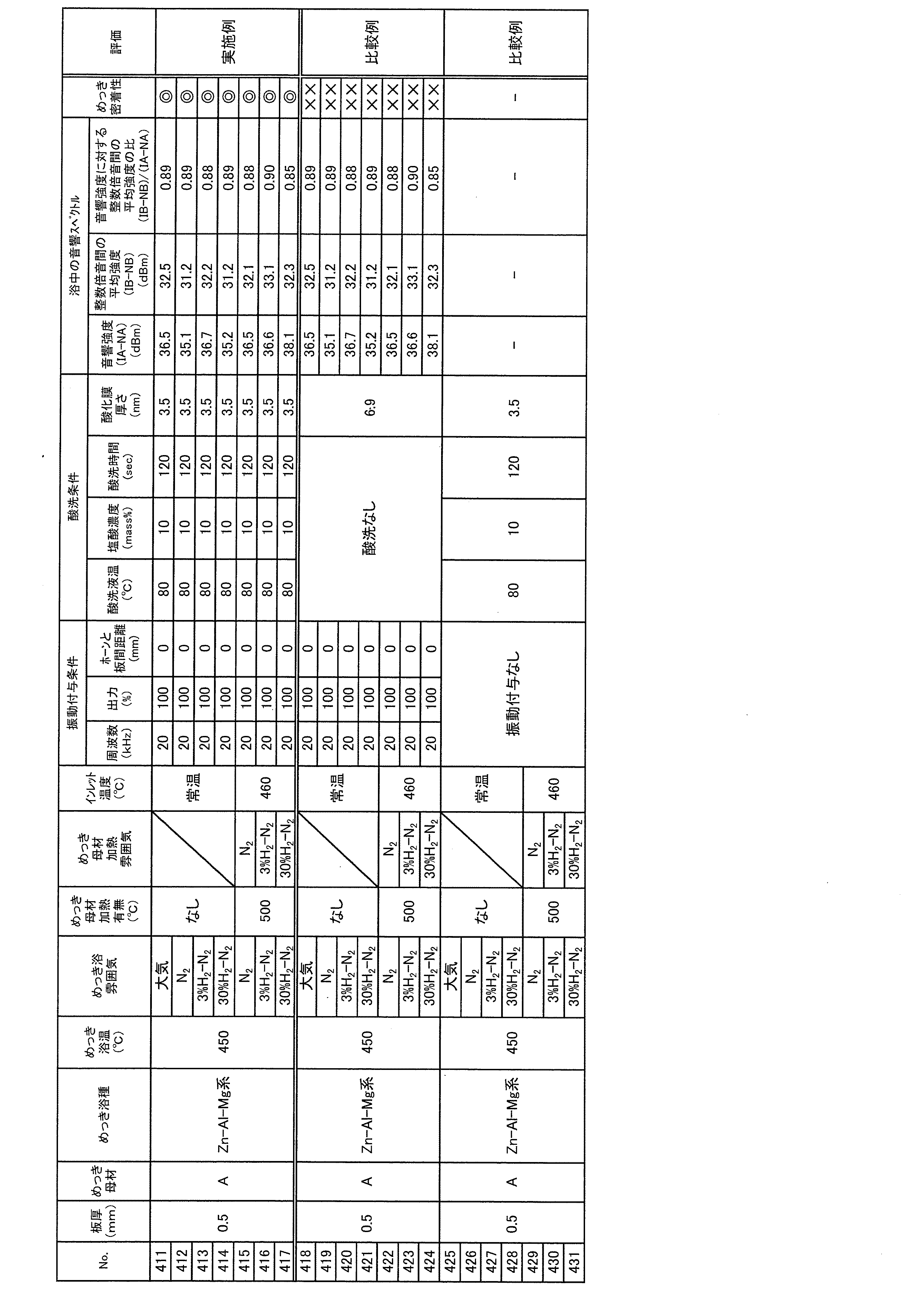
これに対し、前処理として酸洗処理を行うことなく、大気雰囲気または非酸化性雰囲気にて鋼帯を加熱した後、スナウト中の雰囲気を大気雰囲気または非酸化性雰囲気として、鋼帯に溶融めっきを行った場合、表15のNo.418~424に示すように、めっき品に対してめっき密着性試験を行った結果のめっき剥離率が80%以上となった。
また、大気雰囲気または非酸化性雰囲気にて鋼帯を加熱した後、スナウト中の雰囲気を大気雰囲気または非酸化性雰囲気として、溶融めっき浴中に振動を付与することなく鋼帯に溶融めっきを行った場合、表15のNo.425~431に示すように、めっき品にめっき層が十分に形成されず、めっき密着性について試験不可であった。
〔附記事項〕
本発明は上述した各実施形態に限定されるものではなく、請求項に示した範囲で種々の変更が可能であり、異なる実施形態にそれぞれ開示された技術的手段を適宜組み合わせて得られる実施形態についても本発明の技術的範囲に含まれる。
本発明は上述した各実施形態に限定されるものではなく、請求項に示した範囲で種々の変更が可能であり、異なる実施形態にそれぞれ開示された技術的手段を適宜組み合わせて得られる実施形態についても本発明の技術的範囲に含まれる。
2 鋼板(金属材料)
2A 鋼帯(金属材料)
20 溶融めっき浴(めっき浴)
2A 鋼帯(金属材料)
20 溶融めっき浴(めっき浴)
Claims (3)
- 溶融金属であるめっき浴中に金属材料を進入させて、上記金属材料に上記溶融金属を被覆させる溶融めっき方法であって、
上記金属材料の表面に形成された酸化膜の厚さを低減する前処理を施す膜厚調整工程と、
上記膜厚調整工程の後、上記溶融金属に上記金属材料が接触している間に上記めっき浴中に振動を付与しつつ上記金属材料に上記溶融金属を被覆させるめっき工程と、を含み、
上記めっき浴に付与する上記振動の周波数を基本周波数として、
上記めっき工程では、上記めっき浴中にて測定される音響スペクトルが下記式(1)の関係を満たすように、上記振動を付与することを特徴とする溶融めっき方法。
(IB-NB)/(IA-NA)>0.2 ・・・(1)
(ここで、
IA:測定周波数帯域全体における音圧の平均値
IB:(i)上記基本周波数における音圧のピークと2倍音周波数における音圧のピークとの間、並びに、(ii)複数の倍音周波数における音圧のピークのうち隣り合うピーク間、の特定周波数帯域における音圧の平均値
NA:上記測定周波数帯域全体における、上記振動を付与していない場合の音圧の平均値
NB:上記IBに関して規定される上記特定周波数帯域における、上記振動を付与していない場合の音圧の平均値
である) - 上記膜厚調整工程では、上記金属材料が上記めっき浴に進入した際の上記酸化膜の厚さが6nm以下となるように上記酸化膜の厚さを低減することを特徴とする請求項1に記載の溶融めっき方法。
- 上記めっき浴は、Znを40質量%以上含有することを特徴とする請求項1または2に記載の溶融めっき方法。
Priority Applications (1)
| Application Number | Priority Date | Filing Date | Title |
|---|---|---|---|
| JP2019561335A JP6841348B2 (ja) | 2018-11-06 | 2019-11-06 | 溶融めっき方法 |
Applications Claiming Priority (4)
| Application Number | Priority Date | Filing Date | Title |
|---|---|---|---|
| JP2018209243 | 2018-11-06 | ||
| JP2018-209243 | 2018-11-06 | ||
| JP2019150571 | 2019-08-20 | ||
| JP2019-150571 | 2019-08-20 |
Publications (1)
| Publication Number | Publication Date |
|---|---|
| WO2020095940A1 true WO2020095940A1 (ja) | 2020-05-14 |
Family
ID=70610714
Family Applications (2)
| Application Number | Title | Priority Date | Filing Date |
|---|---|---|---|
| PCT/JP2019/043454 Ceased WO2020095939A1 (ja) | 2018-11-06 | 2019-11-06 | 溶融めっき方法 |
| PCT/JP2019/043455 Ceased WO2020095940A1 (ja) | 2018-11-06 | 2019-11-06 | 溶融めっき方法 |
Family Applications Before (1)
| Application Number | Title | Priority Date | Filing Date |
|---|---|---|---|
| PCT/JP2019/043454 Ceased WO2020095939A1 (ja) | 2018-11-06 | 2019-11-06 | 溶融めっき方法 |
Country Status (8)
| Country | Link |
|---|---|
| US (1) | US11566315B2 (ja) |
| EP (1) | EP3878998A4 (ja) |
| JP (2) | JP6841348B2 (ja) |
| KR (1) | KR102548252B1 (ja) |
| CN (1) | CN113166915A (ja) |
| MX (1) | MX2021004818A (ja) |
| TW (2) | TWI797393B (ja) |
| WO (2) | WO2020095939A1 (ja) |
Families Citing this family (1)
| Publication number | Priority date | Publication date | Assignee | Title |
|---|---|---|---|---|
| US12571068B2 (en) | 2020-07-14 | 2026-03-10 | Jfe Steel Corporation | Continuous annealing line, continuous hot-dip galvanizing line, and steel sheet production method |
Citations (4)
| Publication number | Priority date | Publication date | Assignee | Title |
|---|---|---|---|---|
| JPS55100969A (en) * | 1979-01-23 | 1980-08-01 | Asahi Glass Co Ltd | Manufacture of hot galvanized metal plate |
| JPS59145771A (ja) * | 1983-02-08 | 1984-08-21 | Sumitomo Electric Ind Ltd | 連続溶融めつき方法 |
| JPH02282456A (ja) * | 1989-04-21 | 1990-11-20 | Nisshin Steel Co Ltd | 金属帯の超音波照射連続溶融めっき法 |
| JPH03229849A (ja) * | 1990-02-05 | 1991-10-11 | Furukawa Electric Co Ltd:The | Al又はAl合金線棒管材の表面被覆方法 |
Family Cites Families (6)
| Publication number | Priority date | Publication date | Assignee | Title |
|---|---|---|---|---|
| US2895845A (en) * | 1955-12-07 | 1959-07-21 | Aeroprojects Inc | Method for applying metallic coatings |
| JPH02125850A (ja) | 1988-11-02 | 1990-05-14 | Kawasaki Steel Corp | 連続溶融亜鉛めっき方法 |
| JPH07316770A (ja) * | 1994-05-19 | 1995-12-05 | Tokyo Seiko Co Ltd | 加振連続溶融めっき方法 |
| CN1132266A (zh) * | 1995-03-25 | 1996-10-02 | 中国人民解放军国防科学技术大学 | 超声快速热浸镀 |
| JP2000064020A (ja) * | 1998-08-21 | 2000-02-29 | Ajikawa Tekko Kensetsu Kk | 溶融Al−Zn合金めっき方法 |
| JP2001303224A (ja) * | 2000-04-27 | 2001-10-31 | Kawasaki Steel Corp | 溶融金属めっき方法および溶融金属めっき装置 |
-
2019
- 2019-11-06 JP JP2019561335A patent/JP6841348B2/ja active Active
- 2019-11-06 CN CN201980071034.0A patent/CN113166915A/zh active Pending
- 2019-11-06 US US17/288,519 patent/US11566315B2/en active Active
- 2019-11-06 TW TW108140282A patent/TWI797393B/zh active
- 2019-11-06 TW TW108140281A patent/TW202033792A/zh unknown
- 2019-11-06 KR KR1020217016341A patent/KR102548252B1/ko active Active
- 2019-11-06 WO PCT/JP2019/043454 patent/WO2020095939A1/ja not_active Ceased
- 2019-11-06 MX MX2021004818A patent/MX2021004818A/es unknown
- 2019-11-06 EP EP19881403.0A patent/EP3878998A4/en not_active Withdrawn
- 2019-11-06 JP JP2019561340A patent/JP6841349B2/ja active Active
- 2019-11-06 WO PCT/JP2019/043455 patent/WO2020095940A1/ja not_active Ceased
Patent Citations (4)
| Publication number | Priority date | Publication date | Assignee | Title |
|---|---|---|---|---|
| JPS55100969A (en) * | 1979-01-23 | 1980-08-01 | Asahi Glass Co Ltd | Manufacture of hot galvanized metal plate |
| JPS59145771A (ja) * | 1983-02-08 | 1984-08-21 | Sumitomo Electric Ind Ltd | 連続溶融めつき方法 |
| JPH02282456A (ja) * | 1989-04-21 | 1990-11-20 | Nisshin Steel Co Ltd | 金属帯の超音波照射連続溶融めっき法 |
| JPH03229849A (ja) * | 1990-02-05 | 1991-10-11 | Furukawa Electric Co Ltd:The | Al又はAl合金線棒管材の表面被覆方法 |
Also Published As
| Publication number | Publication date |
|---|---|
| TWI797393B (zh) | 2023-04-01 |
| EP3878998A1 (en) | 2021-09-15 |
| US11566315B2 (en) | 2023-01-31 |
| JP6841348B2 (ja) | 2021-03-10 |
| KR20210080544A (ko) | 2021-06-30 |
| TW202033792A (zh) | 2020-09-16 |
| KR102548252B1 (ko) | 2023-06-27 |
| JPWO2020095940A1 (ja) | 2021-02-15 |
| TW202028492A (zh) | 2020-08-01 |
| JPWO2020095939A1 (ja) | 2021-02-15 |
| US20210388477A1 (en) | 2021-12-16 |
| EP3878998A4 (en) | 2022-06-01 |
| WO2020095939A1 (ja) | 2020-05-14 |
| JP6841349B2 (ja) | 2021-03-10 |
| MX2021004818A (es) | 2021-06-15 |
| CN113166915A (zh) | 2021-07-23 |
Similar Documents
| Publication | Publication Date | Title |
|---|---|---|
| RU2621501C1 (ru) | Формованное горячей штамповкой изделие и способ изготовления формованного горячей штамповкой изделия | |
| CN103228813B (zh) | 热浸镀Al-Zn系钢板 | |
| JP7259974B2 (ja) | 連続焼鈍装置及び連続溶融亜鉛めっき装置、並びに鋼板の製造方法 | |
| JP6211908B2 (ja) | ホットスタンプ成形品の製造方法 | |
| JP6014681B2 (ja) | 極低温接合性に優れた溶融亜鉛めっき鋼板及びその製造方法 | |
| JP2011006785A (ja) | 溶融Al−Zn系めっき鋼板 | |
| WO2012070694A1 (ja) | 溶融Al-Zn系めっき鋼板およびその製造方法 | |
| CN107267905A (zh) | 用于模压淬火应用的镀锌钢材以及生产方法 | |
| CN105980610A (zh) | 等离子体电解氧化的构件及其制造方法 | |
| JP7737027B2 (ja) | 方向性電磁鋼板及びその製造方法 | |
| CN106795612B (zh) | 高强度热浸镀锌钢板 | |
| JP6841348B2 (ja) | 溶融めっき方法 | |
| JPH02217489A (ja) | 合金化亜鉛めっき帯鋼の製法 | |
| JP2001011596A (ja) | 溶融金属めっき金属帯の製造方法 | |
| EP3907304B1 (en) | High-strength hot-dip galvanized steel sheet and method for producing same | |
| JP7421082B2 (ja) | 溶融めっき方法 | |
| EP4166681A1 (en) | Dehydrogenation device, system for manufacturing steel sheet, and method for manufacturing steel sheet | |
| JP4720618B2 (ja) | 合金化溶融亜鉛めっき鋼板及びその製造方法 | |
| JP7234739B2 (ja) | 高強度溶融めっき鋼帯の製造方法 | |
| JP5644059B2 (ja) | 合金化溶融亜鉛めっき鋼板及びその製造方法 | |
| JP3580541B2 (ja) | 加工性と加工部耐食性に優れた表面処理鋼板及びその製造方法 | |
| JP2015199995A (ja) | 自動車部材の製造方法 | |
| JPH1058027A (ja) | 鋼材の脱スケール方法および脱スケール装置 | |
| JPH02225652A (ja) | 高鮮映性鋼板の製造方法 | |
| JPH09324249A (ja) | 溶融金属めっき装置および溶融金属めっき熱間圧延鋼帯の製造方法 |
Legal Events
| Date | Code | Title | Description |
|---|---|---|---|
| ENP | Entry into the national phase |
Ref document number: 2019561335 Country of ref document: JP Kind code of ref document: A |
|
| 121 | Ep: the epo has been informed by wipo that ep was designated in this application |
Ref document number: 19882459 Country of ref document: EP Kind code of ref document: A1 |
|
| NENP | Non-entry into the national phase |
Ref country code: DE |
|
| 122 | Ep: pct application non-entry in european phase |
Ref document number: 19882459 Country of ref document: EP Kind code of ref document: A1 |