WO2020090766A1 - 積層パン生地の成形方法および成形装置 - Google Patents
積層パン生地の成形方法および成形装置 Download PDFInfo
- Publication number
- WO2020090766A1 WO2020090766A1 PCT/JP2019/042246 JP2019042246W WO2020090766A1 WO 2020090766 A1 WO2020090766 A1 WO 2020090766A1 JP 2019042246 W JP2019042246 W JP 2019042246W WO 2020090766 A1 WO2020090766 A1 WO 2020090766A1
- Authority
- WO
- WIPO (PCT)
- Prior art keywords
- bread dough
- shutter
- dough
- laminated
- pressing
- Prior art date
Links
Images


Classifications
-
- A—HUMAN NECESSITIES
- A21—BAKING; EDIBLE DOUGHS
- A21C—MACHINES OR EQUIPMENT FOR MAKING OR PROCESSING DOUGHS; HANDLING BAKED ARTICLES MADE FROM DOUGH
- A21C11/00—Other machines for forming the dough into its final shape before cooking or baking
-
- A—HUMAN NECESSITIES
- A23—FOODS OR FOODSTUFFS; TREATMENT THEREOF, NOT COVERED BY OTHER CLASSES
- A23P—SHAPING OR WORKING OF FOODSTUFFS, NOT FULLY COVERED BY A SINGLE OTHER SUBCLASS
- A23P20/00—Coating of foodstuffs; Coatings therefor; Making laminated, multi-layered, stuffed or hollow foodstuffs
- A23P20/20—Making of laminated, multi-layered, stuffed or hollow foodstuffs, e.g. by wrapping in preformed edible dough sheets or in edible food containers
Definitions
- the present invention relates to a method and an apparatus for forming a laminated bread dough, such as a melon bread, in which a bread dough is covered with a top dough. More specifically, the present invention relates to a method and an apparatus for forming a laminated bread dough that allows the entire surface of the bread dough to be adhered to the surface of the bread dough.
- Patent Document 1 discloses a technique for forming a laminated bread dough by sequentially placing a plurality of bowl-shaped cups having different shapes and performing an eccentric motion on a bread dough on which a dough is placed.
- Patent Document 2 discloses a technique of forming a laminated bread dough by covering a dough on which a top dough is placed with a quadrangular cup that performs eccentric motion.
- Patent Document 3 after pressing the dough on which the top dough is placed with a mold member via a release sheet made of flexible cloth from above, the top dough and the upper surface of the dough are brought into close contact with each other.
- a technique of forming a laminated bread dough by eccentrically rotating a forming frame body having a stepped protrusion on the inner circumference.
- Patent Document 4 a laminated dough is formed while the bread dough on which the overwrapping dough is placed is horizontally rotated by repeatedly pressing and relaxing by a holding and conveying surface and a pressing unit that faces the holding and conveying surface and moves toward and away from the holding and conveying surface. Techniques for doing so are disclosed.
- the present invention is for solving the above-mentioned problems, and is a method for forming a laminated bread dough, comprising: (a) supporting a laminated bread dough having a top dough placed on the upper surface of the bread dough with a support member, and a plurality of shutter pieces. And (c) closing the shutter so that the pressing surface of the shutter piece presses the laminated bread dough from the entire circumference to cover the side surface of the bread dough with the cover. A step of adhering the dough and enlarging it by flushing the laminated bread dough upward, (e) pressing the laminated bread dough against the shutter and the supporting member with a pressing die to bring the top dough into close contact with the bread dough. And a step of allowing the step to be performed.
- the pressing die is lowered to press the laminated bread dough.
- step (e) the laminated bread dough on the upper side, which is swept upward and expands, is pressed by the pressing die (step e3).
- a method of forming a laminated bread dough comprising: (d) a step of opening the shutter to separate the pressing surface from the laminated bread dough between the step (c) and the step (e).
- step (e) step of lowering the pressing die to press and flatten the laminated bread dough against the support member (step e4), and (g) raising the pressing die after the step (e4))
- step (b) the laminated bread dough is pressed against the support member by the pressing die to bring the dough into close contact with the bread dough, and then the pressing is performed. Separating the mold from the laminated bread dough.
- the pressing surface inclined toward the center side of the opening region from the upper surface to the lower surface of the shutter piece moves the peripheral portion of the top dough to the bottom of the bread dough. Is characterized by.
- the bottom surface of the pressing die is formed in a concave shape by one or a plurality of blades, and a pattern of the blades is attached to a surface of the overcloth.
- the bottom surface of the pressing die is formed of a stretchable sheet, and the sheet is deformed into a concave shape to press the laminated bread dough.
- the method is characterized in that the step subsequent to the step (e) includes a step (f) of closing the shutter to press the laminated bread dough against the pressing die.
- a laminated bread dough forming device and a top dough is placed on the bread dough to form a laminated bread dough, a shutter composed of a plurality of shutter pieces, and a shutter arranged below the shutter.
- Supporting shutter and a pressing die and while supporting the laminated bread dough having the dough placed on the upper surface of the bread dough with the support member, the shutter is closed from the state in which it is arranged in the opening area of the shutter.
- the pressing surface of the shutter piece presses the laminated bread dough from the entire circumferential direction, and the pressing die presses the laminated bread dough against the shutter and the support member.
- the laminated bread dough having the dough placed on the upper surface of the bread dough is supported by the support member, and the shutter is closed from the state in which it is arranged in the opening area of the shutter. Then, the laminated bread dough is pressed from the entire circumferential direction by the pressing surface of the shutter piece, the pressing die is lowered to press the laminated bread dough on the shutter and the support member, and after the pressing die is raised, the It is characterized in that the shutter is closed so that the pressing surface of the shutter piece presses the laminated bread dough from the entire circumferential direction.
- the laminated bread dough having the dough placed on the upper surface of the bread dough is supported by the support member, and the shutter is closed from the state in which it is arranged in the opening area of the shutter. Then, the laminated bread dough is pressed from the entire circumferential direction by the pressing surface of the shutter piece, the shutter is opened to separate the pressing surface from the laminated bread dough, and the pressing die descends to form the laminated bread dough. After pressing the support member and raising the pressing die, the shutter is closed and the pressing surface of the shutter piece presses the laminated bread dough from the entire circumferential direction.
- the pressing surface is formed so as to be inclined toward the center side of the opening region from the upper surface of the shutter piece toward the lower surface.
- the bottom surface of the pressing die is formed in a concave shape by one or a plurality of blades.
- the bottom surface of the pressing die is configured by a stretchable sheet.
- the top dough can be brought into close contact with the surface of the bread dough by pressing the top dough against the bread dough with a shutter or a pressing die. Also, after forming a pattern with grooves on the upper surface of the laminated bread dough with a pressing die, the opening area of the shutter is reduced and the laminated bread dough is swept upward to enlarge the upper side, so that the pattern on the upper surface of the laminated bread dough becomes clearer. Can be something.
- the forming apparatus 1 is for forming a laminated bread dough P in which the bread dough P1 is covered with the overlay dough P2.
- the bread dough P1 is used as confectionery bread dough and the overlay dough P2 is used as the biscuit dough to form a melon bread.
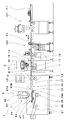
- the molding apparatus 1 includes a top cloth feeding device 3, a shutter molding device 5, a gauge roller device 101, an alignment device 103, and a control device 33 that controls a driving unit of each device. There is.
- the top cloth dough supply device 3 includes a belt conveyor 7 that conveys the bread dough P1, a discharge unit 9 that supplies the top cloth P2 to the upper surface of the bread dough P1, and a feeding device 11 that supplies the top cloth P2 to the discharge unit 9. I have it. Further, on the upstream side of the top dough supply device 3, there is provided a counter roller type gauge roller device 101 for flattening the adjusted bread dough P1 and a discharge portion 9 following the center position of the flat bread dough P1 in the width direction. An aligning device 103 for aligning is provided.
- the belt conveyor 7 includes a photoelectric sensor 13 that detects the conveyance of the bread dough P1.
- the sensor 13 is arranged above the belt conveyor 7 on the upstream side, which is the inlet side of the belt conveyor 7.
- the belt conveyor 7 is provided with an encoder (not shown), and the control device 33 calculates the conveyance position of the bread dough P1 based on the signal from the encoder and the detection signal from the sensor 13 and the length L of the bread dough P1 in the conveyance direction R. Is calculated.
- the discharge part 9 includes a housing 16 having a discharge port 15 formed on the lower surface, and a rotary valve 17 in the housing 16.
- the rotary valve 17 is formed with a communication hole 18 that communicates the flow path on the side of the feeding device 11 and the discharge port 15, and the rotation of the rotary valve 17 opens and closes the discharge port 15.
- the coat fabric feeding device 3 may be, for example, the device described in Japanese Patent No. 4757617 filed by the present applicant, and a detailed description thereof will be omitted.
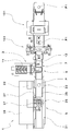
- the shutter forming device 5 is provided with a supply conveyor 23, a shutter device 25, an embossing device 27, a supporting device 29, a carry-out conveyor 31, and a control device 33 for controlling each of these devices on a base 39. That is, in the laminated bread dough forming apparatus 1, the control device 33 that controls the driving unit of each device is provided in the shutter forming device 5, but the control device 33 is provided in another device such as the shutter forming device 5. Alternatively, it may be provided independently.
- the supply conveyor 23 is a belt conveyor for supplying the shutter device 25 with the laminated bread dough P in which the top dough P2 is placed on the upper surface of the bread dough P1.
- the leading end portion 35 of the supply conveyor 23 is provided so as to be capable of reciprocating along the transport direction R between an advanced position (standby position) and a retracted position.
- a photoelectric sensor 37 for detecting the conveyance of the laminated bread dough P is attached to a base 39 on the side of the front end side of the supply conveyor 23.
- the supply conveyor 23 is provided with an encoder (not shown), and the control device 33 calculates the conveyance position of the bread dough P1 based on the signal from the encoder and the detection signal from the sensor 37. Further, the reciprocating movement of the tip portion 35 is controlled by the control device 33 based on the sensing signal from the sensor 37.
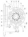
- the shutter device 25 includes a base frame 41 that is attachable to and detachable from the base 39, and nine shutter pieces 45 that are arranged at equal intervals around the center C to surround the center C thereof.
- the shutter 47 is provided.
- a circular through hole 43 is formed in the base frame 41, and the laminated bread dough P formed through the through hole 43 moves downward.
- the plurality of shutter pieces 45 are fixed to nine rotation shafts 49 arranged on the base frame 41 on the circumference S around the center C at equal intervals.
- the rotary shafts 49 are connected to each other by a known power transmission mechanism (not shown) such as a link mechanism or a gear train provided in the base frame 41, and rotate in synchronization with an appropriate drive device. .. By this rotation operation, the shutter pieces 45 are simultaneously swung.
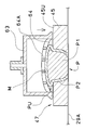
- the shutter piece 45 is provided with a pressing surface 55 facing the center C side of the circumference S.
- the pressing surface 55 is formed as an inclined surface as shown in FIG.
- the pressing surface 55 is formed by a first pressing surface 55A and a second pressing surface 55B that is bent from the first pressing surface 55A and protrudes toward the center C from the upper surface 45U to the lower surface 45L of the shutter piece 45.
- the inclination angles of the first pressing surface 55A and the second pressing surface 55B with respect to the horizontal plane are formed such that the tip end side is smaller than the base end side of the shutter piece 45.
- the pressing surface 55 is a curved surface protruding toward the center C in a plan view.
- the amount of protrusion of the first pressing surface 55A and the second pressing surface 55B toward the center C is formed such that the tip end side of the shutter piece 45 largely protrudes from the base end side.
- At least a portion of the shutter piece 45 that is in contact with the laminated bread dough P is preferably non-adhesive to the laminated bread dough P, and is formed of, for example, a resin material such as high molecular weight polyethylene, polyacetal, or fluororesin.
- the height of the shutter piece 45 is preferably about 1/3 to 2/3 of the height of the laminated bread dough P before forming, but is not limited to this and is suitable for forming the laminated bread dough P. Just do it.
- the shutter 47 opens and closes so as to enlarge or reduce the opening area 61 formed by being surrounded by the pressing surface 55 of each shutter piece 45. Further, when the shutter 47 is opened and closed, the tip end 53 of the shutter piece 45 slides on the pressing surface 55 of the adjacent shutter piece 45 while always being in contact therewith. When the shutter piece 45 swings so that the opening area 61 of the shutter 47 expands or contracts, the opening / closing operation can be temporarily stopped at a position in the middle thereof. The stop position can be adjusted based on a value preset in the control device 33.
- the diameter of the inscribed circle of the opening region 61 at the position of the upper surface 45U of the shutter piece 45 is defined as the opening diameter DI. Further, the diameter of the circumscribed circle of the opening region 61 at the same position is defined as the circumscribed circle diameter DC.
- the center of the opening area 61 coincides with the center C of the circumference S.
- the embossing device 27 is arranged above the shutter device 25.
- the embossing device 27 includes a pressing die 63 and a lifting device 65.
- the pressing die 63 has a cylindrical shape as a whole, and has a cup shape in which a concave portion 64 is formed below.
- the recess 64 is formed by a plurality of blades 64A intersecting each other in a grid pattern.
- the cutting edge of the blade 64A forms a hemispherical concave portion 64 as a whole.
- the upper portion of the blade 64A is a hollow portion 64B (see FIG. 6), and a plurality of exhaust holes 64C formed by the blade 64A communicate with the hollow portion 64B.
- reference numeral 64D (see FIG. 7) is attached to the diameter of the concave portion 64 on the bottom surface of the pressing die 63.
- the pressing die 63 is preferably formed of a material having non-adhesiveness with respect to the overwrap cloth P2, or a metal base material is preferably subjected to non-adhesive surface treatment.
- the elevating device 65 includes a direct-acting actuator 67 that elevates and lowers the pressing die 63 toward and away from the supporting device 29.
- the actuator 67 includes a piston rod 67B that expands and contracts downward from a tubular main body 67A of the actuator 67, and a push die 63 is detachably attached to the lower end of the piston rod 67B.
- the piston rod 67B of the actuator 67 is controlled so that the movable position and the movable speed of expansion and contraction can be adjusted. Further, the piston rod 67B is hollow, and the compressed air A2 is fed into the hollow portion 64B of the pressing die 63 by feeding the compressed air A2 from the compressor or the like into the hollow conduit 67C (see FIG. 6). Is exhausted from the exhaust hole 64C.
- the support device 29 is disposed below the shutter device 25 and supports the bread dough P1 on which the overhanging dough P2 is placed, that is, the laminated bread dough P before forming, and further, the laminated bread dough P that has been formed.
- the supporting device 29 is intermittently driven by an endless conveyor belt 29A that is wound around a plurality of rollers.
- the support device 29 is provided so as to be able to move up and down by interlockingly connecting with a driving means such as a servo motor.
- the conveyor belt 29A moves up and down in the through hole 43 of the base frame 41 of the shutter device 25, and its rising end position is a position in contact with the lower surface 45L of the shutter piece 45.
- the conveyor belt 29A is provided as a support member.
- the carry-out conveyor 31 is a belt conveyor that is continuously provided on the downstream side of the support device 29 that has descended to the descending end position.
- the carry-out conveyor 31 is a device that receives the laminated bread dough P from the support device 29 and further carries it out to the downstream side.
- the surface of the belt conveyor 29 is preferably non-adhesive to the laminated bread dough P, and the belt conveyor 29 is formed of a resin-based material or has a base material coated with a resin material such as polyurethane.
- the bread dough P1 is divided into a required weight from a loaf of bread dough, rounded, and then laid down in a room and adjusted for a required time.
- the bread dough P1 is pressed by the gauge roller device 101, and the bread dough P1 is formed into a substantially circular and flat shape.
- the width W of the bread dough P1 is measured by the aligning device 103 arranged between the gauge roller device 101 and the top dough supplying device 3.
- the bread dough P1 in the width direction of the top dough supply device 3 is aligned with the center position of the discharge port 15 of the top dough supply device 3 in the width direction, the bread dough P1 is overlaid. It is supplied to the belt conveyor 7 of the dough supply device 3.
- the sensor 13 of the belt conveyor 7 detects the conveyance of the bread dough P1.
- the control device 33 calculates the conveyance position and the length L of the bread dough P1 based on the detection signal from the sensor 13.
- the control device 33 causes the feeding device 11 to feed the top dough P2 to the discharging portion 9, and the rotary valve 17 rotates to discharge the dough from the discharge port 15.
- the upper cover dough P2 is discharged, and the thin circular top cover dough P2 is placed so as to substantially cover the conveyed bread dough P1.
- the laminated bread dough P in which the overlaid dough P2 is placed on the bread dough P1 is conveyed by the belt conveyor 7 to the supply conveyor 23 of the shutter forming device 5.
- the leading end portion 35 of the supply conveyor 23 is located at the advanced position that extends downstream so as to cover the shutter 47.
- the control device 33 stops the conveyance of the supply conveyor 23 at a position where the center of the laminated bread dough P coincides with the center C of the opening area 61 of the shutter 47 based on the detection signal for detecting the laminated bread dough P conveyed by the sensor 37. To do.
- the tip end portion 35 moves to the retracted position at once, and the laminated bread dough P placed on the tip end portion 35 falls in the opening area 61 of the shutter 47 enlarged to the set size and rises. It is arranged on the upper surface of the conveyor belt 29A of the stand-by supporting device 29 (arrangement step, see FIG. 6).
- the opening diameter DI of the shutter 47 at this time is referred to as an initial opening diameter.
- the circumscribed circle diameter DC of the opening of the shutter 47 is set smaller than the diameter 64D of the recess 64 of the pressing die 63.
- the opening diameter DI of the shutter 47 is referred to as a first opening diameter (first shutter stop position).
- the laminated bread dough P is pressed from the entire circumferential direction by the pressing surface 55 of the shutter piece 45, and the lower portion PL of the laminated bread dough P is accommodated in the reduced opening area 61 of the shutter 47 and the upper side of the laminated bread dough P.
- the portion PU moves upward from the upper surface of the shutter 47 (synonymous with the upper surface 45U of the shutter piece 45), expands into a substantially hemispherical shape, and is formed into a waist height.
- the shutter 47 adheres the top dough P2 to the side surface of the bread dough P1 and pushes the laminated bread dough P upward to enlarge the upper part into a substantially hemispherical shape to adhere the top dough P2 to the upper surface of the bread dough P1.
- the pressing surface 55 of the shutter piece 45 is formed as an inclined surface. This inclination serves to move the laminated bread dough P upward when the shutter 47 reduces the opening diameter DI and presses the laminated bread dough P from the entire circumferential direction. Further, the second pressing surface 55B formed on the lower side portion of the shutter piece 45 has a function of moving the peripheral edge portion P2E of the top dough P2 on the lower side of the side surface of the laminated bread dough P to the bottom of the bread dough P1 ( Primary pressing step, see FIG. 7).
- the actuator 67 of the embossing device 27 is actuated, and the pressing die 63 descends toward the shutter 47 and the supporting member (conveyor belt 29A).
- the lower end position of the pressing die 63 is set at a position slightly apart from the upper surface of the shutter 47 (synonymous with the upper surface 45U of the shutter piece 45), but is controlled so that it can be adjusted appropriately.
- the concave portion 64 accommodates the upper portion PU of the laminated bread dough P that is enlarged in a substantially hemispherical shape, and the pressing die 63 presses the laminated bread dough P1 against the shutter 47 and the conveyor belt 29A (support member).
- the recesses 64 of the pressing die 63 are formed in a lattice shape by the plurality of blades 64A. Therefore, by pressing the upper portion of the laminated bread dough P in which the concave portion 64 is enlarged in a substantially hemispherical shape, a lattice-shaped pattern M is formed by the grooves on the upper portion of the laminated bread dough P. In this embossing step, the whole top dough P2 is brought into close contact with the surface of the bread dough P1 (secondary pressing step, see FIG. 8).
- the shutter 47 is slightly closed to reduce the opening area 61.
- the opening diameter DI is referred to as the second opening diameter (secondary stop position of the shutter).
- the laminated bread dough P in the reduced opening area 61 moves upward, and the upper portion PU of the laminated bread dough P is further expanded into a substantially hemispherical shape.
- the laminated bread dough P expanded in a substantially hemispherical shape is further strongly pressed by the recesses 64 of the pressing die 63, is raised in each exhaust hole 64C of the recesses 64, and the lattice-shaped pattern M is formed more clearly and The effect that the entire dough P2 is brought into close contact with the surface of the bread dough P1 is improved (third pressing step, see FIG. 9).
- the pressing die 63 is lifted by the actuator 67 and stands by at the rising end position until the next laminated bread dough P is arranged.
- the compressed air A2 is discharged from the exhaust hole 64C through the pipe 67C of the piston rod 67B and the hollow portion 64B of the push die 63 for the required time T, and the push die 63 is applied to the top cloth P2.
- the shutter 47 slightly opens and stops.
- the opening diameter DI is set larger than, for example, the first opening diameter in the above-described primary pressing step, and is referred to as the third opening diameter (third stop position of the shutter).
- the pressing surface 55 of the shutter 47 that opens is separated from the laminated bread dough P (step of separating the shutter, see FIG. 10).
- the shutter 47 closes to the set position and stops.
- the opening diameter DI is preferably set to be smaller than the second opening diameter of the above-described second stop position and is referred to as the fourth opening diameter (the fourth stop position of the shutter).
- the shutter 47 that closes reduces the opening area 61 again.
- the pressing surface 55 of the shutter piece 45 again touches the side surface of the laminated bread dough P from the entire circumferential direction, and further presses the dough P2 on the side surface of the bread dough P1.
- the laminated bread dough P moves upward from within the opening region 61, and the upper portion PU of the laminated bread dough P is further expanded into a substantially hemispherical shape.
- the pattern M of the upper portion PU of the laminated bread dough P is expanded, and the thickness of the overcoat dough P2 forming the groove becomes thin.
- the second pressing surface 55B of the shutter piece 45 moves the peripheral edge portion P2E of the top dough P2 to the lower side of the peripheral edge portion P1E of the bottom portion of the bread dough P1 and covers the bread dough P1 with the top dough P2.
- the shutter 47 can bring the entire dough P2 on the bread dough P1 into close contact with the bread dough P1 (fourth pressing step, see FIG. 11).
- the shutter 47 opens to move to the initial position, expands the opening area 61, and releases the laminated bread dough P.
- the lower portion PL of the laminated bread dough P spreads slightly in the radial direction, and the bulge of the upper portion PU of the bread dough P1 enlarged in a substantially hemispherical shape becomes slightly smaller, and the upper portion of the laminated bread dough P becomes larger.
- the pattern M shrinks and the groove becomes slightly deeper (release process, see FIG. 12).
- the supporting device 29 on which the formed laminated bread dough P is placed descends to the descending stop position. Then, the laminated bread dough P is transferred from the supporting device 29 to the carry-out conveyor 31 and further carried out to the next process such as the secondary forming device and the heat treatment device (carry-out process).
- the description of the forming device 1 for the laminated bread dough P according to the first embodiment of the present invention is generally as described above, but the present invention is not limited to this, and various modifications can be made within the scope and scope of the claims. It is possible.
- the steps from the arranging step (see FIG. 5) of arranging the laminated bread dough P in which the overlaid dough P2 is placed on the upper surface of the bread dough P1 (see FIG. 5) to the fourth pressing step (see FIG. 10) are performed.
- the pressing process is performed by the pressing mold 63 (secondary pressing process, see FIG. 8)
- the forming process of the laminated bread dough P can be completed.
- the lower part of the laminated bread dough P supported by the supporting member is surrounded by the shutter 47, and the upper part of the laminated bread dough P is embossed by the pressing die 63.
- the entire circumference of the laminated bread dough P can be surrounded by the respective members, and the whole overlaid dough P2 can be brought into close contact with the bread dough P.
- the shutter 47 is closed to perform the primary pressing step (see FIG. 7) of pressing the laminated bread dough P with the pressing surface 55, but after the placement step, By lowering the pressing die 63 and slightly pressing the laminated bread dough P between the supporting member and the support member, a preliminary pressing step of preliminarily adhering the bread dough P1 and the overlaid dough P2 can be performed.
- a preliminary pressing step of preliminarily adhering the bread dough P1 and the overlaid dough P2 can be performed.
- this pre-pressing when there is a bubble due to a gap between the bread dough P1 and the top dough P2, this bubble can be discharged to the outside.
- the lowering position of the pressing die 63 is set lower than the lowering position during the secondary pressing process.
- the pre-pressing may be performed after placing the top dough P2 on the bread dough P1.
- a forming device similar to the gauge roller device 101 is provided between the top dough supply device 3 and the shutter forming device. It is also possible to do it before the placement step.
- the shutter forming device 6 provided in the forming device 1 for the laminated bread dough P according to the second embodiment of the present invention will be described with reference to FIG.
- the same components as those in the first embodiment are designated by the same reference numerals, and detailed description thereof will be omitted.
- description will be made assuming that the laminated bread dough P having a shell pattern formed on the surface called concha is formed.
- the shutter forming device 6 includes a base 39, a supply conveyor 24, a shutter device 26, an embossing device 27, and a control device 33 that controls each device.
- the supply conveyor 24 is a belt conveyor for supplying the laminated bread dough P in which the top dough P2 is placed on the upper surface of the bread dough P1 below the shutter device 26.
- a sensor 37 for detecting the conveyance of the laminated bread dough P is attached to a base 39 on the upstream side of the supply conveyor 24.
- the supply conveyor 24 is provided with an encoder (not shown), and the control device 33 calculates the transport position of the laminated bread dough P based on the signal from the encoder and the sensing signal from the sensor 37.
- the conveyor belt 24A of the supply conveyor 24 is a support member for the laminated bread dough P.
- the shutter device 26 includes a base frame 41 that is attachable to and detachable from the elevating base 40 of the base 39, and a shutter 47 that is composed of nine shutter pieces 45 that are arranged at equal intervals on the lower surface of the base frame 41.
- the shutter device 26 is arranged above the supply conveyor 24, and the shutter 47 moves away from and approaches the supply conveyor 24 when the elevating base 40 is moved up and down.
- the pressing die 68 of the embossing device 27 can move up and down in the through hole 43 of the base frame 41 of the shutter device 26 and the opening area 61 of the shutter 47, and moves toward and away from the supply conveyor 24.
- the recess 69 of the pressing die 68 is formed so that the plurality of blades 69A expand in a fan shape.
- the cutting edge of the blade 69A forms a hemispherical concave portion 69 as a whole.
- the pressing die 68 has a hollow portion 69B at the upper part of the blade 69A, and a plurality of exhaust holes 69C formed between the plurality of blades 69A communicate with the hollow portion 69B.
- the push die 68 is detachably attached to the lower end of the piston rod 67B of the actuator 67.
- a process of forming the laminated bread dough P by the shutter forming device 6 will be described with reference to FIGS. 13 to 17.
- the laminated bread dough P in which the top dough P2 is placed on the bread dough P1 is conveyed to the supply conveyor 24 of the shutter forming device 6 by the belt conveyor 7 of the top dough supply device 3.
- the supply conveyor 24 stops the conveyance of the laminated bread dough P at a position where the center of the laminated bread dough P coincides with the center C of the opening region 61 of the shutter 47.
- the shutter device 26 descends and stops at the position where the lower surface 45L of the shutter piece 45 contacts the upper surface of the conveyor belt 24A. At this time, the laminated bread dough P is arranged in the opening area 61 of the shutter 47 enlarged to the set size (arrangement step, see FIG. 14).
- the opening diameter DI of the shutter 47 at this time is referred to as an initial opening diameter.
- the shutter piece 45 rotates synchronously toward the center C (the opening area 61 is reduced), and the shutter piece 45 closes and temporarily stops until the opening diameter DI reaches the first opening diameter (of the shutter). Primary stop position).
- the laminated bread dough P is accommodated in the opening area 61 of the shutter 47 in which the lower portion PL of the laminated bread dough P is reduced, and the upper portion PU of the laminated bread dough P moves upward from the upper surface of the shutter 47 and is substantially hemispherical. Expanded to a high waist.
- the second pressing surface 55B of the shutter piece 45 moves the peripheral edge portion P2E of the top dough P2 located below the side surface of the laminated bread dough P to the bottom of the bread dough P1.
- the bread dough P1 is covered with the overwrap dough P2 and is in close contact with each other (first pressing step, see FIG. 15).
- the shutter 47 opens to expand the opening region 61 to the initial position (initial opening diameter) and separate from the laminated bread dough P (separation step).
- the pressing die 68 of the embossing device 27 descends toward the supporting member (conveyor belt 24A) and stops at the set position.
- the pressing die 68 presses the laminated bread dough P against the support member 24A
- the side surface of the laminated bread dough P having a high waist protrudes to the outside.
- the protruding dough P2 covers the peripheral edge portion P1E of the bottom surface of the flattened dough P1.
- a shell-shaped pattern M is formed by grooves on the upper surface of the laminated bread dough P (secondary pressing step, see FIG. 16).
- the press die 68 is supplied with compressed air A2 as it rises, and is separated from the laminated bread dough P without adhering to the overwrap dough P2.
- the shutter 47 closes and stops to a position set to reduce the opening area 61.
- the opening diameter DI is preferably set to be the same as or smaller than the first opening diameter at the primary stop position of the shutter described above.
- the opening diameter DI is referred to as a second opening diameter (secondary stop position of the shutter).
- the pressing surface 55 of the shutter piece 45 again touches the side surface of the laminated bread dough P from the entire circumferential direction, and further presses the dough P2 on the side surface of the bread dough P1.
- the laminated bread dough P moves upward from within the opening region 61, and the upper portion PU of the laminated bread dough P is further expanded into a substantially hemispherical shape (third pressing step, see FIG. 17).
- the shutter 47 opens to expand the opening area 61 to the initial position and release the laminated bread dough P.
- the lower portion PL of the laminated bread dough P spreads slightly in the radial direction, the bulge of the upper portion PU of the bread dough P1 that has expanded to a substantially hemispherical shape becomes slightly smaller, and the groove of the pattern M is slightly deeper. (Release step, see FIG. 18).
- the shutter device 26 rises, and the formed laminated bread dough P is carried out by the supply conveyor 24 to the next process such as the secondary molding device and the heat treatment device (carry-out process). Even when the shutter molding device 6 is used, it is possible to perform the preliminary pressing step after the disposing step, as described above.
- a shutter forming device 6 provided in the forming device 1 for the laminated bread dough P according to the third embodiment of the present invention will be described with reference to FIG.
- the same components as those in the second embodiment are designated by the same reference numerals, and detailed description thereof will be omitted.
- description will be made assuming that a laminated bread dough P, which is called a chocolate chip melon bread and uses a biscuit dough in which chocolate chips are mixed as the top dough P2, is formed.
- the pressing die 81 of the embossing device 27 includes a bowl-shaped member 83 having a hollow portion 83A that opens downward, a release sheet 85 made of stretchable and flexible cloth, and a ring made of an elastic material such as rubber. Of the ring 87.
- the release sheet 85 is formed of, for example, a cloth made of nylon, polyurethane, polyester fiber, or the like, a cloth made of silicone rubber, fluororubber, or the like.
- An annular groove 83B is formed on the outer peripheral surface of the bowl-shaped member 83.
- the release sheet 85 covers the hollow portion 83A and the outer peripheral surface, is fixed to the groove 83B by the ring 87, and forms the bottom surface of the pressing die 81.
- the push die 81 is detachably attached to the lower end of the piston rod 67B of the actuator 67.
- FIGS. 19 to 22 A process of forming the laminated bread dough P by the shutter forming device 6 will be described with reference to FIGS. 19 to 22.
- the laminated bread dough P in which the overlaid dough P2 is placed on the upper surface of the bread dough P1 is arranged in the opening region 61 of the shutter 47 which has been enlarged to the initial opening diameter (arrangement step, see FIG. 19).
- the center of the laminated bread dough P is displaced from the center C of the opening region 61 of the shutter 47.
- the shutter piece 45 rotates synchronously toward the center C (the opening region 61 shrinks), the opening diameter DI closes to the position of the first opening diameter, and temporarily stops (the shutter first position). Primary stop position).
- the bread dough P1 not covered with the top dough P2 is pressed by the pressing surface 55 of each shutter piece 45, and the center of the laminated bread dough P is positioned at the center C of the shutter 47 (first Next pressing step, positioning step, see FIG. 20).
- the shutter 47 opens to expand the opening region 61 to the initial position (initial opening diameter), and the shutter piece 45 separates from the laminated bread dough P (separation step).
- the pressing die 81 descends toward the support member (conveyor belt 24A) and stops at the set position.
- the release sheet 85 is extended inside the bowl-shaped member 83 (hollow portion 83A) and deformed into a concave shape.
- the upper dough P2 and the lower dough P1 in the upper part extend in the radial direction and are flattened, and the upper dough P2 covers the upper surface of the dough P1. (Second pressing step, see FIG. 21).
- the pressing die 81 rises, and the release sheet 85 separates from the top cloth P2. At this time, the release sheet 85 is gradually reduced and deformed to prevent the release sheet 85 from adhering to the cover fabric P2.
- the shutter 47 closes and stops at the position where the opening diameter DI becomes the second opening diameter.
- the opening diameter DI is preferably set smaller than the above-described first opening diameter (secondary stop position of the shutter).
- the pressing surface 55 of the shutter piece 45 touches the side surface of the laminated bread dough P from the entire circumferential direction and presses the dough P2 on the side surface of the bread dough P1.
- the laminated bread dough P moves upward from within the opening region 61, and the upper portion PU of the laminated bread dough P is enlarged into a substantially hemispherical shape.
- the second pressing surface 55B of the shutter piece 45 moves the peripheral edge portion P2E of the top dough P2 to the lower side of the peripheral edge portion P1E of the bottom portion of the bread dough P1 and covers the bread dough P1 with the top dough P2.
- the shutter 47 can bring the whole of the overlaid dough P2 into close contact with the bread dough P1 (third pressing step, see FIG. 22).
- the shutter 47 opens to expand the opening region 61 to the initial position and release the laminated bread dough P (release process). Further, the shutter device 26 moves up, and the formed laminated bread dough P is carried out by the supply conveyor 24 (carrying-out step).
- the third pressing step is performed only once, but it is possible to perform a further pressing step by repeating the opening / closing operation of the shutter 47 a plurality of times.
- the opening diameter DI for closing the shutter 47 is set to be the same as the second opening diameter (see FIG. 22), or preferably set to be gradually smaller.
- the compressed air A2 can be supplied to the pressing die 68 when the pressing die 81 moves up.
- the compressed air A2 is discharged from the release sheet 85, and the effect of preventing the sticking to the cover fabric P2 is improved.
- the release sheet is a thin rubber sheet, the compressed air A2 can expand the release sheet downward, and the effect of preventing adhesion to the cover fabric P2 is improved.
- the shutter forming device 8 provided in the forming device 1 for the laminated bread dough P according to the fourth embodiment of the present invention will be described with reference to FIG.
- the same components as those in the first embodiment are designated by the same reference numerals, and detailed description thereof will be omitted.
- the supporting device 29 including a supporting member (conveyor belt 29A) moves up and down from below with respect to the pressing die 63 and the shutter 47 that are fixed at a set position without moving up and down.
- the shutter forming device 8 is provided with a supply conveyor 24, a shutter device 26, an embossing device 28, a supporting device 29, a carry-out conveyor 31, and a control device 33 for controlling each device on a base 39.
- the supply conveyor 24 is a belt conveyor for supplying the laminated bread dough P in which the top dough P2 is placed on the upper surface of the bread dough P1 to the support device 29.
- the shutter device 26 is detachably attached to an elevating base 40 set at a predetermined vertical position with respect to a base 39.
- the pressing die 63 of the embossing device 28 is attached to a bracket 71 fixed to the front surface of the base 39 via a hollow screw member 73 so that its vertical position can be adjusted.
- the pressing die 63 is arranged inside the through hole 43 of the base frame 41 with a predetermined gap from the upper surface 45U of the shutter piece 45. Further, by feeding the compressed air A2 from the compressor or the like to the hollow screw member 73, the compressed air A2 is fed to the hollow portion 64B of the pressing die 63 and exhausted from the exhaust hole 64C.
- the support device 29 is disposed below the shutter device 25, and moves up and down so as to approach and separate from the shutter 47 while supporting the laminated bread dough P before forming which is supplied from the supply conveyor 24.
- the carry-out conveyor 31 is a belt conveyor that is continuously provided on the downstream side of the support device 29 that has descended to the descending end position.
- the carry-out conveyor 31 is a device that receives the laminated bread dough P from the support device 29 and further carries it out to the downstream side.
- the laminated bread dough P in which the overlaid dough P2 is placed on the bread dough P1 is conveyed from the supply conveyor 24 to the support device 29.
- the control device 33 stops the conveyance of the support device 29 at the position where the center of the laminated bread dough P coincides with the center C of the opening region 61 of the shutter 47 based on the detection signal obtained by the sensor 37 detecting the laminated bread dough P.
- the supporting device 29 rises and stops at the position where the upper surface of the conveyor belt 24A contacts the lower surface 45L of the shutter piece 45. At this time, the laminated bread dough P is arranged in the opening area 61 of the shutter 47 enlarged to the set size (arrangement step, see FIG. 24).
- the opening diameter DI of the shutter 47 at this time is referred to as an initial opening diameter.
- the shutter piece 45 rotates synchronously toward the center C (the opening area 61 shrinks), closes to the set position, and temporarily stops (stop position of the shutter).
- the laminated bread dough P is pressed as the opening area 61 of the shutter 47 is reduced (the diameter of the opening is reduced), and the upper portion PU of the laminated bread dough P moves upward from the upper surface of the shutter 47 and expands in a substantially hemispherical shape.
- the laminated bread dough P which expands in a substantially hemispherical shape, enters the recess 64 of the pressing die 63 and eventually contacts the blade 64A.
- a lattice-shaped pattern M is formed on the laminated bread dough P (embossing step). The depth of the groove of the pattern M varies depending on the size of the opening region 61 of the shutter 47, as shown in FIGS. 8 and 9, for example.
- the laminated bread dough P is accommodated in an area surrounded by the pressing die 63, the shutter 47 and the supporting member (conveyor belt 29A), and is pressed from the entire circumference by reducing the opening area 61 of the shutter 47.
- the whole overlaid dough P2 comes into close contact with the bread dough P1 (pressing step).
- the shutter 47 opens to the initial position, and the supporting device 29 on which the formed laminated bread dough P is placed descends to the descending stop position (release process). Then, the laminated bread dough P is transferred from the support device 29 to the carry-out conveyor 31 and carried out (carry-out step).
- the embossing device 28 can be modified so that the pressing die 63 can be lifted and lowered like the embossing device 27 according to the first embodiment. In this case, after the pressing step, as shown in FIG. 10 and FIG. 11, the pressing die 63 is moved up and the shutter 47 is opened and closed to form the laminated bread dough P to a waist height, and the laminated bread dough P is formed above the laminated bread dough P.
- the printed pattern M can be clarified.
- the description of the forming device 1 for the laminated bread dough P according to the embodiment of the present invention is generally as described above, but the present invention is not limited to this, and various modifications can be made within the scope and scope of the claims. ..
- the support member has been described as the conveyor belt 24A of the supply conveyor 24, but the supply conveyor 24 may be replaced with a rotary table device and a rotating table may be used as the support member.
- the concave portion 64 of the pressing die 63 is formed by the plurality of blades 64A
- the surface shape of the concave portion 64 may be a desired pattern to be transferred to the surface of the laminated bread dough P and may be formed from a plurality of uneven surfaces. May be. Further, it may be a hemisphere without a pattern. Further, it is possible to perform the pressing step similar to the molding step according to the second embodiment of the present invention with the shutter molding device 5 according to the first embodiment of the present invention.
- the opening / closing operation of the shutter 47 can be repeated a plurality of times with the pressing die being raised, and the lower portion PL of the laminated bread dough P can be pressed a plurality of times.
- the inclined pressing surface 55 of the shutter piece 45 can move the peripheral edge portion P2E of the top dough P2 to the bottom surface of the bread dough P1.
- the shape of the pressing surface 55 of the shutter piece 45 has been described as the first pressing surface 55A and the second pressing surface 55B being bent, but a plurality of times so as to project from the upper surface 45U toward the lower surface 45L toward the center C side. It is also possible to form a bent shape or an arc shape of a part of a circle or an ellipse.
- the shutter may have three or more shutter pieces and can open and close the opening area. Not only the shutter swings around the rotation axis, but also the shutter pieces slide back and forth to reciprocate. It may be configured to.
- each process in each embodiment may be performed in another embodiment, and a modification in each process is applied to another process. May be done.
Landscapes
- Life Sciences & Earth Sciences (AREA)
- Engineering & Computer Science (AREA)
- Food Science & Technology (AREA)
- Chemical & Material Sciences (AREA)
- Polymers & Plastics (AREA)
- Manufacturing And Processing Devices For Dough (AREA)
- Formation And Processing Of Food Products (AREA)
- Bakery Products And Manufacturing Methods Therefor (AREA)
Abstract
本発明は従来技術の問題を解決するものであり、パン生地の表面に上掛け生地全体を密着することができる積層パン生地の成形方法および成形装置を提供することを課題とする。パン生地(P1)に上掛け生地(P2)を載置し、積層パン生地(P)とする上掛け生地供給装置(3)と、複数のシャッタ片(45)から構成されるシャッタ(47)と、シャッタ(47)の下方に配置される支持部材(29A)と、押し型(63)とを備え、パン生地(P1)の上面に上掛け生地(P2)を載置した積層パン生地(P)を全周より囲んだ状態で押圧する積層パン生地の成形装置。
Description
本発明は、例えばメロンパン等の、パン生地に上掛け生地を被覆した積層パン生地の成形方法および成形装置に関する。より詳細には、パン生地の表面に上掛け生地全体を密着することができる積層パン生地の成形方法および成形装置に関する。
パン生地に上掛け生地を被覆した積層パンを成形する技術として、あらかじめパン生地の上面に上掛け生地を載置し、偏心運動するカップ状部材によって丸め成形を行い、パン生地の表面に上掛け生地を被覆することが知られている。例えば、特許文献1には偏心運動を行う、形状の異なった複数の椀状カップを上掛け生地を載置したパン生地に順次被せて積層パン生地を成形する技術が開示されている。また、特許文献2には偏心運動を行う四角形状のカップを、上掛け生地を載置したパン生地に被せて積層パン生地を成形する技術が開示されている。
また、特許文献3には、上掛け生地を載置したパン生地を、柔軟性を有する布地からなる離型シートを介した型部材で上方から押圧し上掛け生地とパン生地の上面を密着させた後、内周に段差状の突起を備えた成形枠体を偏心回転して積層パン生地を成形する技術が開示されている。
また、特許文献4には、上掛け生地を載置したパン生地を、保持搬送面と当該保持搬送面に対向し接近離反する押圧手段で挟圧・緩和を繰り返し水平に回転させながら積層パン生地を成形する技術が開示されている。
特許文献1乃至3に記載のカップや成形枠体を用いた成形方法においては、カップや成形枠体の内壁が積層パン生地に接触する衝撃で上掛け生地がパン生地から剥離するという問題がある。また、カップや成形枠体内での積層パン生地の転動を制御することは極めて難しいため、上掛け生地がパン生地の表面を均一にむらなく被覆できない場合がある。また、特許文献4に記載の成形方法においては、上掛け生地を載置したパン生地をその両側面のみから挟圧するため、積層パン生地の下側部分が長円状に変形し、一度密着した上掛け生地がパン生地から剥離するという問題がある。
本発明は上記課題を解決するためのものであり、積層パン生地の成形方法であって、(a)パン生地の上面に上掛け生地を載置した積層パン生地を支持部材で支持し、複数のシャッタ片から構成されるシャッタの開口領域内に配置する工程、(c)前記シャッタを閉動作して前記シャッタ片の押圧面で前記積層パン生地を全周方向から押圧して前記パン生地の側面に前記上掛け生地を密着させるとともに、前記積層パン生地を上方に押し流して上方を拡大する工程、(e)押し型にて前記積層パン生地を前記シャッタ及び前記支持部材に押圧して前記パン生地に前記上掛け生地を密着させる工程、を含むことを特徴とする。
また、積層パン生地の成形方法であって、前記工程(e)では、前記押し型を下降して前記積層パン生地を押圧することを特徴とする。
また、積層パン生地の成形方法であって、(g)前記押し型を上昇させる工程、(i)前記シャッタを閉動作して前記シャッタ片の押圧面で前記積層パン生地を全周方向から押圧するとともに、前記積層パン生地を上方に押し流して上方を拡大する工程、をさらに含むことを特徴とする。
また、積層パン生地の成形方法であって、、前記工程(e)では、上方に押し流されて拡大する、上方の前記積層パン生地が前記押し型に押圧される(工程e3)ことを特徴とする。
また、積層パン生地の成形方法であって、前記工程(c)と前記工程(e)の間に、(d)前記シャッタを開動作して前記押圧面を前記積層パン生地から離す工程、を含み、前記工程(e)では、(押し型を下降して前記積層パン生地を前記支持部材に押圧して偏平化させる工程(工程e4)、前記工程(e4)の後に、(g)前記押し型を上昇させる工程、(i)前記シャッタを閉動作して前記シャッタ片の押圧面で前記積層パン生地を全周方向から押圧するとともに、前記積層パン生地を上方に押し流して上方を拡大する工程、を含むことを特徴とする。
また、前記工程(a)及び前記工程(c)の間に、(b)前記押し型にて前記積層パン生地を前記支持部材に押圧し前記パン生地に前記上掛け生地を密着させ、その後、前記押し型を前記積層パン生地から離間させる工程、を含むことを特徴とする。
また、前記シャッタが閉動作する際に、前記シャッタ片の上面から下面に向かって前記開口領域の中心側に傾斜する前記押圧面が前記上掛け生地の周縁部を前記パン生地の底部に移動することを特徴とする。
また、前記押し型の底面は1又は複数の刃により凹状に形成され、前記上掛け生地の表面に前記刃による模様が付されることを特徴とする。
また、前記押し型の底面は伸縮可能なシートで形成され、前記シートが凹状に変形して前記積層パン生地を押圧することを特徴とする。
また、前記工程(e)の次工程に、(f)前記シャッタを閉動作して、前記積層パン生地を前記押し型に押圧する工程を含むことを特徴とする。
また、積層パン生地の成形装置であって、パン生地に上掛け生地を載置し、積層パン生地とする上掛け生地供給装置と、複数のシャッタ片から構成されるシャッタと、前記シャッタの下方に配置される支持部材と、押し型とを備え、パン生地の上面に上掛け生地を載置した積層パン生地を前記支持部材で支持するとともに、前記シャッタの開口領域内に配置した状態から、前記シャッタが閉動作して前記シャッタ片の押圧面で前記積層パン生地を全周方向から押圧し、前記押し型にて前記積層パン生地を前記シャッタ及び前記支持部材に押圧するよう構成されていることを特徴とする。
また、積層パン生地の成形装置であって、パン生地の上面に上掛け生地を載置した積層パン生地を前記支持部材で支持するとともに、前記シャッタの開口領域内に配置した状態から、前記シャッタが閉動作して前記シャッタ片の押圧面で前記積層パン生地を全周方向から押圧し、前記押し型が下降して前記積層パン生地を前記シャッタ及び前記支持部材に押圧し、前記押し型を上昇した後、前記シャッタが閉動作して前記シャッタ片の押圧面で前記積層パン生地を全周方向から押圧するよう構成されていることを特徴とする。
また、積層パン生地の成形装置であって、パン生地の上面に上掛け生地を載置した積層パン生地を前記支持部材で支持するとともに、前記シャッタの開口領域内に配置した状態から、前記シャッタが閉動作して前記シャッタ片の押圧面で前記積層パン生地を全周方向から押圧し、前記シャッタを開動作して前記押圧面を前記積層パン生地から離し、さらに、前記押し型が下降して前記積層パン生地を前記支持部材に押圧し、前記押し型を上昇した後、前記シャッタが閉動作して前記シャッタ片の押圧面で前記積層パン生地を全周方向から押圧するよう構成されていることを特徴とする。
また、前記押圧面は、前記シャッタ片の上面から下面に向かって前記開口領域の中心側に傾斜して形成されることを特徴とする。
また、前記押し型の底面は、1又は複数の刃により凹状に形成されることを特徴とする。
また、前記押し型の底面は、伸縮可能なシートにより構成されることを特徴とする。
本発明によれば、シャッタや押し型でパン生地に対し上掛け生地を押圧することにより、パン生地の表面に上掛け生地を密着することができる。また、押し型で積層パン生地の上面に溝による模様を形成した後、シャッタの開口領域を縮小して積層パン生地を上方に押し流して上方を拡大することにより、積層パン生地の上面の模様をより明確なものとすることができる。
この出願は、日本国で2018年10月31日に出願された特願2018-205884号に基づいており、その内容は本出願の内容として、その一部を形成する。
また、本発明は以下の詳細な説明により更に完全に理解できるであろう。しかしながら、詳細な説明および特定の実施例は、本発明の望ましい実施の形態であり、説明の目的のためにのみ記載されているものである。この詳細な説明から、種々の変更、改変が、当業者にとって明らかだからである。
出願人は、記載された実施の形態のいずれをも公衆に献上する意図はなく、開示された改変、代替案のうち、特許請求の範囲内に文言上含まれないかもしれないものも、均等論下での発明の一部とする。
本明細書あるいは請求の範囲の記載において、名詞及び同様な指示語の使用は、特に指示されない限り、または文脈によって明瞭に否定されない限り、単数および複数の両方を含むものと解釈すべきである。本明細書中で提供されたいずれの例示または例示的な用語(例えば、「等」)の使用も、単に本発明を説明し易くするという意図であるに過ぎず、特に請求の範囲に記載しない限り本発明の範囲に制限を加えるものではない。
明細書の一部に含まれ、それを構成する添付図面は、本発明の好ましい実施形態を概略的に示し、上述の一般的説明及び以下の好ましい実施形態の詳細な説明と共に、本発明の要旨を説明するのに役立つ。
本発明の第1の実施形態に係る成形装置の全体的構成を示す側面説明図である。
本発明の第1の実施形態に係る成形装置の全体的構成を示す平面説明図である。
本発明の第1の実施形態に係る成形装置に備えられるシャッタ装置の構成を示す平面説明図である。
本発明の第1の実施形態に係る成形装置に備えられるシャッタ装置の構成を示す断面による正面説明図である。
本発明の第1の実施形態に係る成形装置に備えられる押し型の構成を示す下方矢視による斜視説明図である。
本発明の第1の実施形態に係る成形装置による積層パン生地Pの成形工程の説明図である。
本発明の第1の実施形態に係る成形装置による積層パン生地Pの成形工程の説明図である。
本発明の第1の実施形態に係る成形装置による積層パン生地Pの成形工程の説明図である。
本発明の第1の実施形態に係る成形装置による積層パン生地Pの成形工程の説明図である。
本発明の第1の実施形態に係る成形装置による積層パン生地Pの成形工程の説明図である。
本発明の第1の実施形態に係る成形装置による積層パン生地Pの成形工程の説明図である。
本発明の第1の実施形態に係る成形装置による積層パン生地Pの成形工程の説明図である。
本発明の第2の実施形態に係る成形装置に備えられたシャッタ成形装置の全体的構成を示す正面説明図である。
本発明の第2の実施形態に係る成形装置による積層パン生地Pの成形工程の説明図である。
本発明の第2の実施形態に係る成形装置による積層パン生地Pの成形工程の説明図である。
本発明の第2の実施形態に係る成形装置による積層パン生地Pの成形工程の説明図である。
本発明の第2の実施形態に係る成形装置による積層パン生地Pの成形工程の説明図である。
本発明の第2の実施形態に係る成形装置による積層パン生地Pの成形工程の説明図である。
本発明の第3の実施形態に係る成形装置による積層パン生地Pの成形工程の説明図である。
本発明の第3の実施形態に係る成形装置による積層パン生地Pの成形工程の説明図である。
本発明の第3の実施形態に係る成形装置による積層パン生地Pの成形工程の説明図である。
本発明の第3の実施形態に係る成形装置による積層パン生地Pの成形工程の説明図である。
本発明の第4の実施形態に係る成形装置に備えられたシャッタ成形装置の全体的構成を示す正面説明図である。
本発明の第4の実施形態に係る成形装置による積層パン生地Pの成形工程の説明図である。
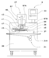
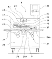
本発明の第1の実施形態に係る積層パン生地の成形装置1について図1乃至図5にて説明する。成形装置1は、パン生地P1を上掛け生地P2で被覆した積層パン生地Pを成形するものであり、例えば、パン生地P1を菓子パン生地、上掛け生地P2をビスケット生地としてメロンパンを成形するものとして説明する。図1及び図2を参照するに、成形装置1は、上掛け生地供給装置3、シャッタ成形装置5、ゲージローラ装置101、整列装置103及び各装置の駆動部を制御する制御装置33を備えている。
上掛け生地供給装置3は、パン生地P1を搬送するベルトコンベヤ7、上掛け生地P2をパン生地P1の上面に供給する吐出部9及び吐出部9に上掛け生地P2を送給する送給装置11を備えている。また、上掛け生地供給装置3の上流側には、調整されたパン生地P1を偏平化する対向ローラ式のゲージローラ装置101、及び偏平のパン生地P1の幅方向の中心位置を後続する吐出部9に位置合わせする整列装置103が備えられている。
ベルトコンベヤ7は、パン生地P1の搬送を感知する光電式のセンサ13を備えている。センサ13は、ベルトコンベヤ7の入口側である上流側で、ベルトコンベヤ7の上方に配置されている。ベルトコンベヤ7はエンコーダ(図示省略)を備え、制御装置33がエンコーダからの信号とセンサ13からの感知信号に基づきパン生地P1の搬送位置を算出するとともにパン生地P1の搬送方向Rに沿った長さLを算出している。
吐出部9は、吐出口15を下面に形成するハウジング16と、ハウジング16内にロータリバルブ17を備えている。ロータリバルブ17には、送給装置11側の流路と吐出口15を連通する連通孔18が形成され、ロータリバルブ17の回動により吐出口15を開閉する。上掛け生地供給装置3は、例えば、本出願人が出願した特許第4757617号に記載された装置でよく、詳細な説明は省略する。
シャッタ成形装置5は、基台39に供給コンベヤ23、シャッタ装置25、型押し装置27、支持装置29、搬出コンベヤ31及びこれらの各装置を制御する前記制御装置33を備えている。すなわち、積層パン生地の成形装置1では、各装置の駆動部を制御する制御装置33はシャッタ成形装置5に備えられているが、制御装置33は、シャッタ成形装置5等の他の装置に備えられても、独立して備えられてもよい。供給コンベヤ23は、パン生地P1の上面に上掛け生地P2が載置された積層パン生地Pをシャッタ装置25に供給するためのベルトコンベヤである。供給コンベヤ23の先端部35は、搬送方向Rに沿って進出位置(待機位置)と後退位置との間で往復動可能に備えられている。供給コンベヤ23の先端側の側方には、積層パン生地Pの搬送を感知する光電式のセンサ37が基台39に取り付けられている。供給コンベヤ23はエンコーダ(図示省略)を備え、制御装置33がエンコーダからの信号とセンサ37からの感知信号に基づきパン生地P1の搬送位置を算出する。また、先端部35の往復動は、センサ37からの感知信号に基づき制御装置33により制御される。
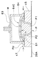
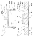
図3及び図4を参照するに、シャッタ装置25は、基台39に着脱可能なベースフレーム41、その中心Cを囲むべく中心周りに等間隔に配置された9個のシャッタ片45により構成されるシャッタ47を備えている。ベースフレーム41には、円形の通孔43が形成され、この通孔43を通って成形された積層パン生地Pが下方に移動する。
複数のシャッタ片45は、ベースフレーム41上にその中心C周りの円周S上に等間隔に配置された9つの回動軸49に軸止されている。各回動軸49は、ベースフレーム41内に備えられた、例えば、リンク機構や歯車列などの公知の動力伝達機構(図示省略)により連結されており、適宜の駆動装置により同期して回動する。この回動動作によりシャッタ片45は、一斉に揺動する。
シャッタ片45は、円周Sの中心C側に面した押圧面55が設けられている。押圧面55は、図4に示すように、傾斜面に形成してある。押圧面55は、シャッタ片45の上面45Uから下面45Lに向かって、第1押圧面55Aと第1押圧面55Aから屈曲して中心C側に突出する第2押圧面55Bにより形成される。第1押圧面55Aと第2押圧面55Bにおいて水平面に対する傾斜角は、それぞれ、シャッタ片45の基端部側に対し先端部側が小さい角度に形成してある。また、押圧面55は、平面視において中心Cに向けて張り出した曲面となっている。第1押圧面55Aと第2押圧面55Bにおいて中心C側への突出量は、それぞれ、シャッタ片45の基端部側に対し先端部側が大きく突出して形成してある。シャッタ片45の少なくとも積層パン生地Pに接する部位は、積層パン生地Pに対し非粘着性を有することが好ましく、例えば、高分子量ポリエチレン、ポリアセタール、フッ素樹脂などの樹脂材から形成される。なお、シャッタ片45の高さは、成形前の積層パン生地Pの高さの1/3~2/3程度とするのが好ましいが、これには限定されず、積層パン生地Pの成形に適していればよい。
シャッタ47は、各シャッタ片45の押圧面55によって囲まれて形成される開口領域61を拡大、縮小するよう開閉動作する。また、シャッタ47が開閉動作する際、シャッタ片45の先端53は、隣接するシャッタ片45の押圧面55に常に接した状態を保ちつつ、これに摺動する。シャッタ片45は、シャッタ47の開口領域61が拡大、縮小するよう揺動する際、その途中の位置にて一時的に開閉動作が停止可能である。その停止位置は、制御装置33に予め設定された値に基づき調整可能である。ここでは、平面視において、シャッタ片45の上面45Uの位置での開口領域61の内接円の直径を開口径DIとする。また、同位置での開口領域61の外接円の直径を外接円径DCとする。開口領域61の中心は、円周Sの中心Cに一致する。
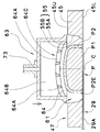
型押し装置27は、シャッタ装置25の上方に配置されている。型押し装置27は、押し型63と昇降装置65を備えている。押し型63は、全体として円柱状であり、下方に凹部64が形成されたカップ形状である。図5を参照するに、凹部64は、複数の刃64Aが格子状に交差して形成される。この刃64Aの刃先が全体として半球面状の凹部64を形成するものである。押し型63は、刃64Aの上部を中空部64B(図6参照)とするとともに、刃64Aにて形成される複数の排気孔64Cが前記中空部64Bと連通する。ここでは、押し型63の底面における凹部64の直径に符合64D(図7参照)を付す。押し型63は、上掛け生地P2に対し非粘着性を有する材料から形成され、あるいは金属製の母材に非粘着性の表面処理が施されていることが好ましい。
昇降装置65は、押し型63を支持装置29に接近及び離反するよう昇降させる直動式のアクチュエータ67を備えている。アクチュエータ67は、アクチュエータ67の筒状の本体67Aから下方に向かって伸縮するピストンロッド67Bを備えており、このピストンロッド67Bの下端に押し型63が着脱交換可能に装着されている。
アクチュエータ67のピストンロッド67Bは、伸縮する可動位置や可動速度を調整可能に制御されている。また、ピストンロッド67Bは中空状であり、この中空の管路67C(図6参照)にコンプレッサなどから圧縮空気A2を送給することにより、押し型63の中空部64Bに圧縮空気A2が送り込まれ、排気孔64Cから排気される。
支持装置29は、シャッタ装置25の下方に配置され、上掛け生地P2が載置されたパン生地P1、すなわち、成形する前の積層パン生地P、を支持し、さらには、成形が終了した積層パン生地Pを後述する搬出コンベヤ31へ搬送するベルトコンベヤである。支持装置29は、無端状のコンベヤベルト29Aが複数のローラに掛け回されて間欠駆動される。支持装置29は、例えば、サーボモータのごとき駆動手段と連動連結することにより昇降可能に備えられている。コンベヤベルト29Aは、シャッタ装置25のベースフレーム41の通孔43内を昇降し、その上昇端位置は、シャッタ片45の下面45Lに接する位置である。ここでは、コンベヤベルト29Aが支持部材として備えられる。搬出コンベヤ31は、下降端位置に降下した支持装置29の下流側に連設されたベルトコンベヤである。搬出コンベヤ31は、積層パン生地Pを支持装置29から受け取り、さらに、下流側へ搬出する装置である。ベルトコンベヤ29の表面は、積層パン生地Pに対し非粘着性を有することが好ましく、ベルトコンベヤ29は、樹脂系の材料から形成され、あるいは母材にポリウレタンなどの樹脂材が被覆されている。また、ベルトコンベヤ29の搬送面に小麦粉などの粉体を散粉することで積層パン生地Pとの粘着を防ぐことができる。
次に、本発明の第1の実施形態に係る成形装置1による積層パン生地Pの成形工程について図6乃至図12にて説明する。パン生地P1は、パン生地の塊から所要重量に分割され、丸め成形された後、所要時間、室内にて寝かされ調整される。パン生地P1がゲージローラ装置101にて押圧され、パン生地P1が略円形で偏平状に形成される。パン生地P1は、ゲージローラ装置101と上掛け生地供給装置3との間に配設された整列装置103にて幅Wが計測される。そして、上掛け生地供給装置3の幅方向でのパン生地P1の中心位置が上掛け生地供給装置3の吐出口15の幅方向の中心位置に一致するよう位置合わせされた後に、パン生地P1は上掛け生地供給装置3のベルトコンベヤ7に供給される。
ベルトコンベヤ7のセンサ13は、パン生地P1の搬送を検出する。制御装置33は、センサ13からの検出信号に基づきパン生地P1の搬送位置及び長さLを算出する。制御装置33は、パン生地P1がベルトコンベヤ7の所要の位置まで搬送されると、送給装置11が上掛け生地P2を吐出部9に送給し、ロータリバルブ17の回動により吐出口15から上掛け生地P2を吐出し、略円形で薄片の上掛け生地P2を搬送されるパン生地P1に概ね覆うように載置する。パン生地P1に上掛け生地P2を載置した積層パン生地Pは、ベルトコンベヤ7によりシャッタ成形装置5の供給コンベヤ23に搬送される。
供給コンベヤ23の先端部35は、シャッタ47の上方を覆うように下流側へ伸びた進出位置にある。制御装置33は、センサ37が搬送される積層パン生地Pを感知する感知信号に基づき、積層パン生地Pの中心がシャッタ47の開口領域61の中心Cに一致する位置にて供給コンベヤ23の搬送を停止する。
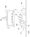
次いで、先端部35は一気に後退位置まで移動し、先端部35上に載置されていた積層パン生地Pは、設定された大きさに拡大したシャッタ47の開口領域61内を落下し、上昇して待機している支持装置29のコンベヤベルト29Aの上面に配置される(配置工程、図6参照)。このときのシャッタ47の開口径DIを初期開口径と称す。
そして、9つの回動軸49が一斉に閉方向に回動することにより、シャッタ片45が支持部材であるコンベヤベルト29Aに摺動しながら中心Cに向かって同期して回動し(開口領域61が縮小し)、設定された位置まで閉動作して一時的に停止する。シャッタ47の開口の外接円径DCは、押し型63の凹部64の直径64Dより小さく設定される。ここでは、シャッタ47の開口径DIを第1開口径と称す(シャッタの第1次停止位置)。このとき、積層パン生地Pは、シャッタ片45の押圧面55により全周方向から押圧され、積層パン生地Pの下側部分PLが縮小したシャッタ47の開口領域61内に収容され、積層パン生地Pの上側部分PUがシャッタ47の上面(シャッタ片45の上面45Uと同義)より上方へ移動し略半球状に拡大し、腰高に成形される。そして、シャッタ47は、パン生地P1の側面に上掛け生地P2を密着させるとともに、積層パン生地Pを上方に押し流して上方を略半球状に拡大して前記パン生地P1の上面に前記上掛け生地P2を密着させる。
シャッタ片45の押圧面55は、傾斜面に形成されている。この傾斜は、シャッタ47が開口径DIを縮小し積層パン生地Pを全周方向から押圧する際に、積層パン生地Pを上方へ移動させる作用をなす。また、シャッタ片45の下側部分に形成される第2押圧面55Bは、積層パン生地Pの側面の下側にある上掛け生地P2の周縁部P2Eをパン生地P1の底部に移動させる作用をなす(第1次押圧工程、図7参照)。
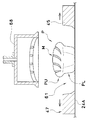
次に、型押し装置27のアクチュエータ67が作動し、押し型63がシャッタ47及び支持部材(コンベヤベルト29A)に向かって下降する。押し型63の下降端位置は、シャッタ47の上面(シャッタ片45の上面45Uに同義)に対し、僅かに離れた位置に設定されているが、適宜調整可能に制御される。凹部64には略半球状に拡大した積層パン生地Pの上側部分PUが収容され、押し型63は、積層パン生地P1をシャッタ47及びコンベヤベルト29A(支持部材)に押圧する。
また、押し型63の凹部64は、複数の刃64Aにより、格子状に構成されている。したがって、凹部64が略半球状に拡大した積層パン生地Pの上側部分を押圧することにより、積層パン生地Pの上部に溝による格子状の模様Mが形成される。この型押し工程において、上掛け生地P2の全体がパン生地P1の表面に密着される(第2次押圧工程。図8参照)。
さらに、シャッタ47が僅かに閉動作して開口領域61を縮小させる。開口径DIを第2開口径と称す(シャッタの第2次停止位置)。縮小した開口領域61内の積層パン生地Pは上方に移動し、積層パン生地Pの上側部分PUをさらに略半球状に拡大させる。略半球状に拡大した積層パン生地Pは、押し型63の凹部64にさらに強く押圧され、凹部64の各排気孔64C内に隆起し、格子状の模様Mがさらに明確に形成されるとともに、上掛け生地P2の全体がパン生地P1の表面に密着される効果が向上する(第3次押圧工程、図9参照)。
押し型63がアクチュエータ67により上昇され、次の積層パン生地Pが配置されるまで上昇端位置にて待機する。押し型63が上昇する際、ピストンロッド67Bの管路67Cと押し型63の中空部64Bを介して排気孔64Cから圧縮空気A2が所要時間Tだけ排出され、押し型63が上掛け生地P2に粘着することなく積層パン生地Pから離れる。そして、シャッタ47が僅かに開動作して停止する。開口径DIは、例えば、上述した第1次押圧工程の際の第1開口径より大きく設定し、第3開口径と称す(シャッタの第3次停止位置)。開動作するシャッタ47の押圧面55は、積層パン生地Pから離れる(シャッタの離反工程、図10参照)。
シャッタ47は、設定した位置まで閉動作して停止する。開口径DIは、好ましくは、上述した第2次停止位置の第2開口径より小さく設定し、第4開口径と称す(シャッタの第4次停止位置)。閉動作するシャッタ47は、再び開口領域61を縮小する。このとき、シャッタ片45の押圧面55は、再び全周方向から積層パン生地Pの側面に触れ、さらに、パン生地P1の側面に上掛け生地P2押圧する。また、開口領域61内から積層パン生地Pが上方に移動し、積層パン生地Pの上側部分PUをさらに略半球状に拡大させる。この略半球状に拡大にともない、積層パン生地Pの上側部分PUの模様Mが拡大され、溝を形成する上掛け生地P2の生地の厚さは薄くなる。
シャッタ片45の第2押圧面55Bは、上掛け生地P2の周縁部P2Eをパン生地P1の底部の周縁部P1Eの下側に移動させ、上掛け生地P2でパン生地P1を被覆する。シャッタ47は、パン生地P1に対し上掛け生地P2の全体を密着させることができる(第4次押圧工程、図11参照)。
シャッタ47は、開動作して初期位置まで移動し、開口領域61を拡大して積層パン生地Pを解放する。解放された積層パン生地Pは、積層パン生地Pの下側部分PLが少し半径方向に広がるとともに、略半球状に拡大したパン生地P1の上側部分PUの膨らみが少し小さくなり、積層パン生地Pの上側部分の模様Mが縮小し、溝が少し深くなる(解放工程。図12参照)。
成形された積層パン生地Pを載せた支持装置29が下降停止位置まで下降する。そして、積層パン生地Pは、支持装置29から搬出コンベヤ31に移乗し、さらに、二次成形装置や熱処理装置などの次工程に搬出される(搬出工程)。
本発明の第1の実施の形態に係る積層パン生地Pの成形装置1の説明は概ね上記の通りであるが、これに限らず、特許請求の範囲の要旨および目的の範囲内において種々の変更が可能である。例えば、上記説明では、パン生地P1の上面に上掛け生地P2を載置した積層パン生地Pを開口領域61内に配置する配置工程(図5参照)から第4次押圧工程(図10参照)までを行うよう説明したが、押し型63による型押し(第2次押圧工程、図8参照)までを行い、積層パン生地Pの成形工程を終了することも可能である。型押しによる第2次押圧工程では、支持部材(コンベヤベルト29A)で支持された積層パン生地Pの下側部分をシャッタ47で囲んだ状態で積層パン生地Pの上側部分を押し型63で型押しすることで、積層パン生地Pの全周を各部材で囲みパン生地Pに対し上掛け生地P2の全体を密着させることができる。
また、上記説明では、配置工程の後、シャッタ47を閉動作して積層パン生地Pを押圧面55で押圧する第1次押圧工程(図7参照)を行うよう説明したが、配置工程の後、押し型63を下降させ、積層パン生地Pを支持部材との間で軽度に押圧することで、パン生地P1と上掛け生地P2を予備的に密着させる予備押圧工程を行うことができる。この予備押圧により、パン生地P1と上掛け生地P2の間に隙間による気泡が存在した場合には、この気泡を外へ排出することができる。また、その後の成形工程においてパン生地P1に対する上掛け生地P2の位置ずれを防ぐことができる。このとき、押し型63の下降位置は、第2次押圧工程の際の下降位置より低く設定される。なお、この予備押圧は、パン生地P1に上掛け生地P2を載置した後に行えばよく、例えば、ゲージローラ装置101と同様な成形装置を上掛け生地供給装置3とシャッタ成形装置の間に備え、配置工程の前に行うことも可能である。
次に、本発明の第2の実施形態に係る積層パン生地Pの成形装置1に備えたシャッタ成形装置6について図13にて説明する。なお、第1の実施形態と同様な構成については同一の符号を付し、詳細な説明は省略する。ここでは、コンチャと称される表面に貝殻模様が形成される積層パン生地Pを成形するものとして説明する。
シャッタ成形装置6は、基台39に供給コンベヤ24、シャッタ装置26、型押し装置27及び各装置を制御する制御装置33を備えている。供給コンベヤ24は、パン生地P1の上面に上掛け生地P2が載置された積層パン生地Pをシャッタ装置26の下方に供給するためのベルトコンベヤである。供給コンベヤ24の上流側の側方には、積層パン生地Pの搬送を感知するセンサ37が基台39に取り付けられている。供給コンベヤ24はエンコーダ(図示省略)を備え、制御装置33がエンコーダからの信号とセンサ37からの感知信号に基づき積層パン生地Pの搬送位置を算出する。ここでは、供給コンベヤ24のコンベヤベルト24Aが積層パン生地Pの支持部材である。
シャッタ装置26は、基台39の昇降ベース40に着脱可能なベースフレーム41、ベースフレーム41の下面に等間隔に配置された9個のシャッタ片45により構成されるシャッタ47を備えている。シャッタ装置26は、供給コンベヤ24の上方に配置され、昇降ベース40の昇降によりシャッタ47が供給コンベヤ24に対し離反・接近する。
型押し装置27の押し型68は、シャッタ装置26のベースフレーム41の通孔43及びシャッタ47の開口領域61内を昇降可能であり、供給コンベヤ24に対し接近離反する。図14に示すように、押し型68の凹部69は、複数の刃69Aが扇状に拡がるように形成される。この刃69Aの刃先が全体として半球面状の凹部69を形成するものである。押し型68は、刃69Aの上部を中空部69Bとするとともに、複数の刃69Aの間に形成される複数の排気孔69Cが前記中空部69Bと連通する。押し型68は、アクチュエータ67のピストンロッド67Bの下端に着脱交換可能に装着されている。
シャッタ成形装置6による積層パン生地Pの成形工程について図13乃至図17にて説明する。パン生地P1に上掛け生地P2を載置した積層パン生地Pは、上掛け生地供給装置3のベルトコンベヤ7によりシャッタ成形装置6の供給コンベヤ24に搬送される。積層パン生地Pがセンサ37に感知されると、積層パン生地Pの中心がシャッタ47の開口領域61の中心Cに一致する位置にて供給コンベヤ24は積層パン生地Pの搬送を停止する。
シャッタ装置26が下降し、シャッタ片45の下面45Lがコンベヤベルト24Aの上面に接する位置にて停止する。このとき、積層パン生地Pが設定された大きさに拡大したシャッタ47の開口領域61内に配置される(配置工程、図14参照)。このときのシャッタ47の開口径DIを初期開口径と称す。
そして、シャッタ片45が中心Cに向かって同期して回動し(開口領域61が縮小し)、開口径DIが第1開口径となる位置まで閉動作して一時的に停止する(シャッタの第1次停止位置)。このとき、積層パン生地Pは、積層パン生地Pの下側部分PLが縮小したシャッタ47の開口領域61内に収容され、積層パン生地Pの上側部分PUがシャッタ47の上面より上方へ移動し略半球状に拡大し、腰高の状態に成形される。また、シャッタ片45の第2押圧面55Bは、積層パン生地Pの側面の下側にある上掛け生地P2の周縁部P2Eをパン生地P1の底部に移動する。パン生地P1は上掛け生地P2に被覆されるとともに、互いに密着する(第1次押圧工程、図15参照)。
シャッタ47は、開動作して初期位置(初期開口径)まで開口領域61を拡大し、積層パン生地Pから離れる(離間工程)。次に、型押し装置27の押し型68が支持部材(コンベヤベルト24A)に向かって下降し設定位置に停止する。押し型68が積層パン生地Pを支持部材24Aに押圧すると、腰高の積層パン生地Pの側面が外側に突き出る。突き出た上掛け生地P2は、偏平化したパン生地P1の底面の周縁部P1Eを被覆する。また、積層パン生地Pの上面には、溝による貝殻状の模様Mが形成される(第2次押圧工程。図16参照)。
押し型68は、上昇するとともに圧縮空気A2が供給され、上掛け生地P2に粘着することなく積層パン生地Pから離れる。押し型68が上昇した後、シャッタ47は、開口領域61を縮小するよう設定した位置まで閉動作して停止する。開口径DIは、好ましくは、上述したシャッタの第1次停止位置での第1開口径と同じ、又は、それより小さく設定する。ここでは、開口径DIを第2開口径と称す(シャッタの第2次停止位置)。このとき、シャッタ片45の押圧面55は、再び全周方向から積層パン生地Pの側面に触れ、さらに、パン生地P1の側面に上掛け生地P2押圧する。また、開口領域61内から積層パン生地Pが上方に移動し、積層パン生地Pの上側部分PUをさらに略半球状に拡大させる(第3次押圧工程。図17参照)。
シャッタ47は、開動作して初期位置まで開口領域61を拡大し、積層パン生地Pを解放する。解放された積層パン生地Pは、積層パン生地Pの下側部分PLが少し半径方向に広がるとともに、略半球状に拡大したパン生地P1の上側部分PUの膨らみが少し小さくなり、模様Mの溝が少し深くなる(解放工程。図18参照)。
シャッタ装置26が上昇し、成形された積層パン生地Pは、供給コンベヤ24により二次成形装置や熱処理装置などの次工程に搬出される(搬出工程)。なお、シャッタ成形装置6を用いる場合においても、配置工程の後に、前述のように、予備押圧工程を行うことも可能である。
上記説明から理解できるように、シャッタ成形装置6においても、第1の実施形態に係るシャッタ成形装置5と同様に、パン生地P1に対し上掛け生地P2の全体を密着させることができる。
次に、本発明の第3の実施形態に係る積層パン生地Pの成形装置1に備えたシャッタ成形装置6について図19にて説明する。なお、第2の実施形態と同様な構成については同一の符号を付し、詳細な説明は省略する。ここでは、チョコチップメロンパンと称される、上掛け生地P2としてチョコチップが混在するビスケット生地を用いた積層パン生地Pを成形するものとして説明する。
型押し装置27の押し型81は、下方に向かって開口する中空部83Aを有する椀状部材83、伸縮可能で柔軟性を有する布地などからなる離型シート85及びゴムなどの弾性素材からなる環状のリング87を備える。離型シート85は、例えば、ナイロン、ポリウレタン、ポリエステル繊維などから作られた布、シリコンゴムあるいはフッ素ゴムなどから作られた布などで形成される。椀状部材83の外周面には、環状の溝83Bが形成される。離型シート85は、中空部83A及び外周面を覆い、溝83Bにリング87にて固定され、押し型81の底面を形成する。押し型81は、アクチュエータ67のピストンロッド67Bの下端に着脱交換可能に装着されている。
シャッタ成形装置6による積層パン生地Pの成形工程について図19乃至図22にて説明する。パン生地P1の上面に上掛け生地P2を載置した積層パン生地Pは、初期開口径まで拡大したシャッタ47の開口領域61内に配置される(配置工程、図19参照)。図19においては、積層パン生地Pの中心がシャッタ47の開口領域61の中心Cに対し位置ずれした状態を示している。
そして、シャッタ片45が中心Cに向かって同期して回動し(開口領域61が縮小し)、開口径DIが第1開口径の位置まで閉動作して一時的に停止する(シャッタの第1次停止位置)。このとき、積層パン生地Pは、上掛け生地P2が被覆されていないパン生地P1が各シャッタ片45の押圧面55により押圧され、積層パン生地Pの中心がシャッタ47の中心Cに位置決めされる(第1次押圧工程、位置決め工程、図20参照)。
シャッタ47は、開動作して初期位置(初期開口径)まで開口領域61を拡大し、シャッタ片45は積層パン生地Pから離れる(離間工程)。次に、押し型81が支持部材(コンベヤベルト24A)に向かって下降し設定位置に停止する。押し型81が積層パン生地Pを支持部材24Aに押圧すると、離型シート85は、椀状部材83の内側(中空部83A)へ伸ばされ凹状に変形する。また、離型シート85を介して押圧される積層パン生地Pは、上部の上掛け生地P2及び下部のパン生地P1が半径方向に伸びるとともに偏平化し、上掛け生地P2がパン生地P1の上面を被覆する。(第2次押圧工程。図21参照)。
押し型81が上昇し、離型シート85が上掛け生地P2から離れる。この際に、離型シート85は、徐々に縮小しながら変形することで、上掛け生地P2への粘着を防止する。シャッタ47は、開口径DIを第2開口径となる位置まで閉動作して停止する。開口径DIは、好ましくは、上述した第1開口径より小さく設定する(シャッタの第2次停止位置)。このとき、シャッタ片45の押圧面55は、全周方向から積層パン生地Pの側面に触れ、パン生地P1の側面に上掛け生地P2押圧する。また、開口領域61内から積層パン生地Pが上方に移動し、積層パン生地Pの上側部分PUを略半球状に拡大させる。
シャッタ片45の第2押圧面55Bは、上掛け生地P2の周縁部P2Eをパン生地P1の底部の周縁部P1Eの下側に移動させ、上掛け生地P2でパン生地P1を被覆する。シャッタ47は、パン生地P1に対し上掛け生地P2の全体を密着させることができる(第3次押圧工程。図22参照)。
シャッタ47は、開動作して初期位置まで開口領域61を拡大し、積層パン生地Pを解放する(解放工程)。さらに、シャッタ装置26が上昇し、成形された積層パン生地Pは、供給コンベヤ24により搬出される(搬出工程)。
なお、上記説明では、第3次押圧工程を一度だけ行うよう説明したが、シャッタ47の開閉動作を複数回繰り返すことにより、さらなる押圧工程を行うことも可能である。このとき、シャッタ47を閉動作する開口径DIを第2開口径(図22参照)と同じか、好ましくは、徐々に小さく設定する。シャッタ47による押圧工程を繰り返すことにより、上掛け生地P2の周縁部P2Eをパン生地P1の下側に移動させ、また、上掛け生地P2をパン生地P1に密着させる効果が向上する。
押し型81が上昇する際に、押し型68に圧縮空気A2を供給することも可能である。離型シート85から圧縮空気A2排出され、上掛け生地P2への粘着を防止する効果が向上する。また、離型シートが薄片のゴムシートの場合には、圧縮空気A2が離型シートを下方に向かって膨張させることができ、上掛け生地P2への粘着を防止する効果が向上する。
次に、本発明の第4の実施形態に係る積層パン生地Pの成形装置1に備えたシャッタ成形装置8について図23にて説明する。なお、第1の実施形態と同様な構成については同一の符号を付し、詳細な説明は省略する。ここでは、上下動することなく設定された位置に固定された押し型63及びシャッタ47に対し、支持部材(コンベヤベルト29A)を備えた支持装置29が下方より上下動する構成である。
シャッタ成形装置8は、基台39に供給コンベヤ24、シャッタ装置26、型押し装置28、支持装置29、搬出コンベヤ31及び各装置を制御する制御装置33を備えている。供給コンベヤ24は、パン生地P1の上面に上掛け生地P2が載置された積層パン生地Pを支持装置29に供給するためのベルトコンベヤである。
第4の実施形態に係るシャッタ装置26は、基台39に対し所定の上下位置に設定された昇降ベース40に着脱可能に取り付けられている。型押し装置28の押し型63は、基台39の前面に固定されたブラケット71に中空のねじ部材73を介して上下位置を調整可能に取り付けられている。押し型63は、ベースフレーム41の通孔43の内側で、シャッタ片45の上面45Uに対し所定の間隔を開けて配置されている。また、中空のねじ部材73にコンプレッサなどから圧縮空気A2を送給することにより、押し型63の中空部64Bに圧縮空気A2が送り込まれ、排気孔64Cから排気される。
支持装置29は、シャッタ装置25の下方に配置され、供給コンベヤ24から供給される成形前の積層パン生地Pを支持した状態でシャッタ47に対し接近・離反するように昇降する。搬出コンベヤ31は、下降端位置に降下した支持装置29の下流側に連設されたベルトコンベヤである。搬出コンベヤ31は、積層パン生地Pを支持装置29から受け取り、さらに、下流側へ搬出する装置である。
シャッタ成形装置8による積層パン生地Pの成形工程について図24などにて説明する。パン生地P1に上掛け生地P2を載置した積層パン生地Pは、供給コンベヤ24から支持装置29に搬送される。制御装置33は、センサ37が積層パン生地Pを感知した感知信号に基づき、積層パン生地Pの中心がシャッタ47の開口領域61の中心Cに一致する位置にて支持装置29の搬送を停止する。
支持装置29が上昇し、コンベヤベルト24Aの上面がシャッタ片45の下面45Lに接する位置にて停止する。このとき、積層パン生地Pが設定された大きさに拡大したシャッタ47の開口領域61内に配置される(配置工程、図24参照)。このときのシャッタ47の開口径DIを初期開口径と称す。
そして、シャッタ片45が中心Cに向かって同期して回動し(開口領域61が縮小し)、設定された位置まで閉動作して一時的に停止する(シャッタの停止位置)。積層パン生地Pは、シャッタ47の開口領域61の縮小(開口の縮径)に伴い押圧され、積層パン生地Pの上側部分PUがシャッタ47の上面より上方へ移動し略半球状に拡大していく。略半球状に拡大する積層パン生地Pは、押し型63の凹部64内に侵入し、やがて刃64Aに当接する。積層パン生地Pの上部には、格子状の模様Mが形成される(型押し工程)。模様Mの溝の深さは、例えば、図8と図9に示されるようにシャッタ47の開口領域61の大小の程度に起因して違いが生じる。
このとき、積層パン生地Pは、押し型63、シャッタ47及び支持部材(コンベヤベルト29A)により囲まれた領域内に収容され、シャッタ47の開口領域61を縮小することにより全周から押圧される。この押圧により、パン生地P1に対し上掛け生地P2の全体が密着する(押圧工程)。
この後、シャッタ47が初期位置まで開動作し、成形された積層パン生地Pを載せた支持装置29が下降停止位置まで下降する(解放工程)。そして、積層パン生地Pは、支持装置29から搬出コンベヤ31に移乗し搬出される(搬出工程)。なお、型押し装置28を第1の実施の形態に係る型押し装置27と同様に押し型63を昇降可能に備えるように変更することも可能である。この場合、上記押圧工程の後、図10及び図11に示すように、押し型63を上昇させ、シャッタ47の開閉動作により、積層パン生地Pを腰高に成形するとともに、積層パン生地Pの上部に形成された模様Mを明確にすることができる。
本発明の実施の形態に係る積層パン生地Pの成形装置1の説明は概ね上記の通りであるが、これに限らず、特許請求の範囲の要旨および目的の範囲内において種々の変更が可能である。例えば、シャッタ成形装置6において、支持部材を供給コンベヤ24のコンベヤベルト24Aで説明したが、供給コンベヤ24を回転テーブル装置に置換し、回転するテーブルを支持部材とすることも可能である。また、押し型63の凹部64を複数の刃64Aで形成するよう説明したが、凹部64の表面形状は、積層パン生地Pの表面に転写する所望の模様であればよく複数の凹凸面から形成されてもよい。さらには、模様のない半球状などであってもよい。また、本発明の第1の実施形態に係るシャッタ成形装置5にて、本発明の第2の実施形態に係る成形工程と同様な押圧工程を行うことも可能である。
また、押し型を上昇させた状態でシャッタ47の開閉動作を複数回繰り返し、積層パン生地Pの下側部分PLを複数回押圧することもできる。この押圧工程を繰り返すことによりシャッタ片45の傾斜する押圧面55が上掛け生地P2の周縁部P2Eをパン生地P1の底面に移動させることができる。
また、シャッタ片45の押圧面55の形状を第1押圧面55Aと第2押圧面55Bとが屈曲したものとして説明したが、上面45Uから下面45Lに向かって中心C側に突出するよう複数回屈曲した形状や、円や楕円の一部の弧状に形成することも可能である。また、シャッタは、3つ以上のシャッタ片を備え、開口領域を開閉可能な構成であればよく、回動軸を中心に揺動するものだけではなく、各シャッタ片が互いに摺接しながら往復動する構成であってもよい。
上記の説明では実施例1~4として説明したが、可能であれば、各実施例でのそれぞれの工程は他の実施例において実行されてもよく、各工程における変形例は他の工程に適用されてもよい。
本明細書及び図面で用いた主な符号を以下に示す。
1 成形装置
3 上掛け生地供給装置
5、6 シャッタ成形装置
23、24 供給コンベヤ
24A コンベヤベルト(支持部材)
25、26 シャッタ装置
27、28 型押し装置
29 支持装置
29A コンベヤベルト(支持部材)
33 制御装置
45 シャッタ片
47 シャッタ
55 押圧面(傾斜面)
55A 第1押圧面
55B 第2押圧面
61 開口領域
63、68、81 押し型
64、69 凹部
64A、69A 刃
83 椀状部材
P 積層パン生地
P1 パン生地
P1E (パン生地の底部の)周縁部
P2 上掛け生地
P2E (上掛け生地の)周縁部
M 模様
1 成形装置
3 上掛け生地供給装置
5、6 シャッタ成形装置
23、24 供給コンベヤ
24A コンベヤベルト(支持部材)
25、26 シャッタ装置
27、28 型押し装置
29 支持装置
29A コンベヤベルト(支持部材)
33 制御装置
45 シャッタ片
47 シャッタ
55 押圧面(傾斜面)
55A 第1押圧面
55B 第2押圧面
61 開口領域
63、68、81 押し型
64、69 凹部
64A、69A 刃
83 椀状部材
P 積層パン生地
P1 パン生地
P1E (パン生地の底部の)周縁部
P2 上掛け生地
P2E (上掛け生地の)周縁部
M 模様
Claims (16)
- 積層パン生地の成形方法であって、
(a)パン生地の上面に上掛け生地を載置した積層パン生地を支持部材で支持し、複数のシャッタ片から構成されるシャッタの開口領域内に配置する工程、
(c)前記シャッタを閉動作して前記シャッタ片の押圧面で前記積層パン生地を全周方向から押圧するとともに、前記積層パン生地を上方に押し流して上方を拡大する工程、
(e)押し型にて前記積層パン生地を前記シャッタ及び前記支持部材に押圧して前記パン生地に前記上掛け生地を密着させる工程、
を含むことを特徴とする該成形方法。 - 請求項1に記載の積層パン生地の成形方法であって、
前記工程(e)では、前記押し型を下降して前記積層パン生地を押圧する、
ことを特徴とする該成形方法。 - 請求項2に記載の積層パン生地の成形方法であって、
(g)前記押し型で前記積層パン生地を押圧した後、前記押し型を上昇させる工程、
(i)前記押し型を上昇させた後、前記シャッタを閉動作して前記シャッタ片の押圧面で前記積層パン生地を全周方向から押圧するとともに、前記積層パン生地を上方に押し流して上方を拡大する工程、
をさらに含むことを特徴とする該成形方法。 - 請求項1に記載の積層パン生地の成形方法であって、
前記工程(e)では、上方に押し流されて拡大する、上方の前記積層パン生地が前記押し型に押圧される(工程e3)、
ことを特徴とする該成形方法。 - 請求項1に記載の積層パン生地の成形方法であって、
前記工程(c)と前記工程(e)の間に、
(d)前記シャッタを開動作して前記押圧面を前記積層パン生地から離す工程、を含み、前記工程(e)では、押し型を下降して前記積層パン生地を前記支持部材に押圧して偏平化させ(工程e4)、
前記工程(e4)の後に、
(g)前記押し型を上昇させる工程、
(i)前記シャッタを閉動作して前記シャッタ片の押圧面で前記積層パン生地を全周方向から押圧するとともに、前記積層パン生地を上方に押し流して上方を拡大する工程、
をさらに含むことを特徴とする該成形方法。 - 請求項1乃至5のいずれかに記載の成形方法であって、前記工程(a)及び前記工程(c)の間に、
(b)前記押し型にて前記積層パン生地を前記支持部材に押圧し前記パン生地に前記上掛け生地を密着させ、その後、前記押し型を前記積層パン生地から離間させる工程、
を含むことを特徴とする該成形方法。 - 請求項1乃至5のいずれかに記載の成形方法であって、前記シャッタが閉動作する際に、前記シャッタ片の上面から下面に向かって前記開口領域の中心側に傾斜する前記押圧面が前記上掛け生地の周縁部を前記パン生地の底部に移動することを特徴とする該成形方法。
- 請求項1乃至5のいずれかに記載の成形方法であって、前記押し型の底面は1又は複数の刃により凹状に形成され、前記上掛け生地の表面に前記刃による模様が付されることを特徴とする該成形方法。
- 請求項1乃至5のいずれかに記載の成形方法であって、前記押し型の底面は伸縮可能なシートで形成され、前記シートが凹状に変形して前記積層パン生地を押圧することを特徴とする該成形方法。
- 請求項1乃至3のいずれかに記載の成形方法であって、前記工程(e)の次工程に、
(f)前記シャッタを閉動作して、前記積層パン生地を前記押し型に押圧する工程を含むことを特徴とする該成形方法。 - 積層パン生地の成形装置であって、
パン生地に上掛け生地を載置し、積層パン生地とする上掛け生地供給装置と、
複数のシャッタ片から構成されるシャッタと、
前記シャッタの下方に配置される支持部材と、
押し型とを備え、
パン生地の上面に上掛け生地を載置した積層パン生地を前記支持部材で支持するとともに、前記シャッタの開口領域内に配置した状態から、前記シャッタが閉動作して前記シャッタ片の押圧面で前記積層パン生地を全周方向から押圧し、前記押し型にて前記積層パン生地を前記シャッタ及び前記支持部材に押圧するよう構成されていることを特徴とする該成形装置。 - 請求項11に記載の積層パン生地の成形装置であって、
パン生地の上面に上掛け生地を載置した積層パン生地を前記支持部材で支持するとともに、前記シャッタの開口領域内に配置した状態から、前記シャッタが閉動作して前記シャッタ片の押圧面で前記積層パン生地を全周方向から押圧し、前記押し型が下降して前記積層パン生地を前記シャッタ及び前記支持部材に押圧し、前記押し型を上昇した後、前記シャッタが閉動作して前記シャッタ片の押圧面で前記積層パン生地を全周方向から押圧するよう構成されていることを特徴とする該成形装置。 - 請求項11に記載の積層パン生地の成形装置であって、
パン生地の上面に上掛け生地を載置した積層パン生地を前記支持部材で支持するとともに、前記シャッタの開口領域内に配置した状態から、前記シャッタが閉動作して前記シャッタ片の押圧面で前記積層パン生地を全周方向から押圧し、前記シャッタを開動作して前記押圧面を前記積層パン生地から離し、さらに、前記押し型が下降して前記積層パン生地を前記支持部材に押圧し、前記押し型を上昇した後、前記シャッタが閉動作して前記シャッタ片の押圧面で前記積層パン生地を全周方向から押圧するよう構成されていることを特徴とする該成形装置。 - 請求項11乃至13のいずれかに記載の成形装置であって、前記押圧面は、前記シャッタ片の上面から下面に向かって前記開口領域の中心側に傾斜して形成されることを特徴とする該成形装置。
- 請求項11乃至13のいずれかに記載の成形装置であって、前記押し型の底面は、1又は複数の刃により凹状に形成されることを特徴とする該成形装置。
- 請求項11乃至13のいずれかに記載の成形装置であって、前記押し型の底面は、伸縮可能なシートにより構成されることを特徴とする該成形装置。
Priority Applications (1)
| Application Number | Priority Date | Filing Date | Title |
|---|---|---|---|
| JP2020553910A JP7194195B2 (ja) | 2018-10-31 | 2019-10-29 | 積層パン生地の成形方法および成形装置 |
Applications Claiming Priority (2)
| Application Number | Priority Date | Filing Date | Title |
|---|---|---|---|
| JP2018205884 | 2018-10-31 | ||
| JP2018-205884 | 2018-10-31 |
Publications (1)
| Publication Number | Publication Date |
|---|---|
| WO2020090766A1 true WO2020090766A1 (ja) | 2020-05-07 |
Family
ID=70463186
Family Applications (1)
| Application Number | Title | Priority Date | Filing Date |
|---|---|---|---|
| PCT/JP2019/042246 WO2020090766A1 (ja) | 2018-10-31 | 2019-10-29 | 積層パン生地の成形方法および成形装置 |
Country Status (2)
| Country | Link |
|---|---|
| JP (1) | JP7194195B2 (ja) |
| WO (1) | WO2020090766A1 (ja) |
Citations (3)
| Publication number | Priority date | Publication date | Assignee | Title |
|---|---|---|---|---|
| JP2003333979A (ja) * | 2002-05-22 | 2003-11-25 | Kobird Co Ltd | 食品成形方法及びその方法に用いる型打装置 |
| JP2009089622A (ja) * | 2007-10-04 | 2009-04-30 | Rheon Autom Mach Co Ltd | 上面曲面成形装置 |
| JP2012249596A (ja) * | 2011-06-03 | 2012-12-20 | Rheon Automatic Machinerty Co Ltd | 包被食品製造装置及び包被食品製造方法 |
-
2019
- 2019-10-29 JP JP2020553910A patent/JP7194195B2/ja active Active
- 2019-10-29 WO PCT/JP2019/042246 patent/WO2020090766A1/ja active Application Filing
Patent Citations (3)
| Publication number | Priority date | Publication date | Assignee | Title |
|---|---|---|---|---|
| JP2003333979A (ja) * | 2002-05-22 | 2003-11-25 | Kobird Co Ltd | 食品成形方法及びその方法に用いる型打装置 |
| JP2009089622A (ja) * | 2007-10-04 | 2009-04-30 | Rheon Autom Mach Co Ltd | 上面曲面成形装置 |
| JP2012249596A (ja) * | 2011-06-03 | 2012-12-20 | Rheon Automatic Machinerty Co Ltd | 包被食品製造装置及び包被食品製造方法 |
Also Published As
| Publication number | Publication date |
|---|---|
| JP7194195B2 (ja) | 2022-12-21 |
| JPWO2020090766A1 (ja) | 2021-09-30 |
Similar Documents
| Publication | Publication Date | Title |
|---|---|---|
| JP5750350B2 (ja) | 包被食品の製造方法及び装置 | |
| CN107249336B (zh) | 包馅食品的成形方法和装置 | |
| FI94712C (fi) | Kone ja menetelmä taikinapohjaisten tuotteiden automaattiseksi muodostamiseksi | |
| KR20140011401A (ko) | 포피식품을 제조하기 위한 셔터장치 및 그 방법 | |
| JP3811789B2 (ja) | 食品用生地整形装置 | |
| WO2020090766A1 (ja) | 積層パン生地の成形方法および成形装置 | |
| JP6811224B2 (ja) | 包被食品の成形方法及びその方法に用いる切断装置 | |
| JP2018027077A (ja) | 包被食品の成形方法および装置 | |
| JP2003333979A (ja) | 食品成形方法及びその方法に用いる型打装置 | |
| JP3400441B1 (ja) | 食品成形方法、及びその装置 | |
| US7036427B2 (en) | Rising crust manufacturing apparatus | |
| JP2012249596A (ja) | 包被食品製造装置及び包被食品製造方法 | |
| JP5073219B2 (ja) | 生地の丸め方法および装置 | |
| JP3587458B2 (ja) | 食品成形装置 | |
| JP2008043235A (ja) | シート状食品生地の折り畳み方法及びその装置 | |
| JP5970139B1 (ja) | パン生地成形装置及び方法 | |
| JP7188710B1 (ja) | 生地成形装置及び方法 | |
| WO2023063320A1 (ja) | 包被食品の成形方法 | |
| JP6100073B2 (ja) | 食品成形方法および装置 | |
| JP2003299472A (ja) | 食品の椀状成形方法とその機構 | |
| WO2024019146A1 (ja) | 折り畳み食品を形成する装置、及び、折り畳み食品の成形方法 | |
| JP2003088350A (ja) | 食品包み込み成形装置 |
Legal Events
| Date | Code | Title | Description |
|---|---|---|---|
| 121 | Ep: the epo has been informed by wipo that ep was designated in this application |
Ref document number: 19877625 Country of ref document: EP Kind code of ref document: A1 |
|
| ENP | Entry into the national phase |
Ref document number: 2020553910 Country of ref document: JP Kind code of ref document: A |
|
| NENP | Non-entry into the national phase |
Ref country code: DE |
|
| 122 | Ep: pct application non-entry in european phase |
Ref document number: 19877625 Country of ref document: EP Kind code of ref document: A1 |