WO2020090633A1 - 真空ポンプ、保護網及び接触部品 - Google Patents
真空ポンプ、保護網及び接触部品 Download PDFInfo
- Publication number
- WO2020090633A1 WO2020090633A1 PCT/JP2019/041795 JP2019041795W WO2020090633A1 WO 2020090633 A1 WO2020090633 A1 WO 2020090633A1 JP 2019041795 W JP2019041795 W JP 2019041795W WO 2020090633 A1 WO2020090633 A1 WO 2020090633A1
- Authority
- WO
- WIPO (PCT)
- Prior art keywords
- protective net
- contact
- vacuum pump
- rotating body
- shape
- Prior art date
- Legal status (The legal status is an assumption and is not a legal conclusion. Google has not performed a legal analysis and makes no representation as to the accuracy of the status listed.)
- Ceased
Links
Images






Classifications
-
- F—MECHANICAL ENGINEERING; LIGHTING; HEATING; WEAPONS; BLASTING
- F04—POSITIVE - DISPLACEMENT MACHINES FOR LIQUIDS; PUMPS FOR LIQUIDS OR ELASTIC FLUIDS
- F04C—ROTARY-PISTON, OR OSCILLATING-PISTON, POSITIVE-DISPLACEMENT MACHINES FOR LIQUIDS; ROTARY-PISTON, OR OSCILLATING-PISTON, POSITIVE-DISPLACEMENT PUMPS
- F04C29/00—Component parts, details or accessories of pumps or pumping installations, not provided for in groups F04C18/00 - F04C28/00
- F04C29/12—Arrangements for admission or discharge of the working fluid, e.g. constructional features of the inlet or outlet
-
- F—MECHANICAL ENGINEERING; LIGHTING; HEATING; WEAPONS; BLASTING
- F04—POSITIVE - DISPLACEMENT MACHINES FOR LIQUIDS; PUMPS FOR LIQUIDS OR ELASTIC FLUIDS
- F04D—NON-POSITIVE-DISPLACEMENT PUMPS
- F04D29/00—Details, component parts, or accessories
- F04D29/70—Suction grids; Strainers; Dust separation; Cleaning
- F04D29/701—Suction grids; Strainers; Dust separation; Cleaning especially adapted for elastic fluid pumps
-
- F—MECHANICAL ENGINEERING; LIGHTING; HEATING; WEAPONS; BLASTING
- F04—POSITIVE - DISPLACEMENT MACHINES FOR LIQUIDS; PUMPS FOR LIQUIDS OR ELASTIC FLUIDS
- F04D—NON-POSITIVE-DISPLACEMENT PUMPS
- F04D19/00—Axial-flow pumps
- F04D19/02—Multi-stage pumps
- F04D19/04—Multi-stage pumps specially adapted to the production of a high vacuum, e.g. molecular pumps
-
- F—MECHANICAL ENGINEERING; LIGHTING; HEATING; WEAPONS; BLASTING
- F04—POSITIVE - DISPLACEMENT MACHINES FOR LIQUIDS; PUMPS FOR LIQUIDS OR ELASTIC FLUIDS
- F04C—ROTARY-PISTON, OR OSCILLATING-PISTON, POSITIVE-DISPLACEMENT MACHINES FOR LIQUIDS; ROTARY-PISTON, OR OSCILLATING-PISTON, POSITIVE-DISPLACEMENT PUMPS
- F04C2220/00—Application
- F04C2220/10—Vacuum
-
- F—MECHANICAL ENGINEERING; LIGHTING; HEATING; WEAPONS; BLASTING
- F04—POSITIVE - DISPLACEMENT MACHINES FOR LIQUIDS; PUMPS FOR LIQUIDS OR ELASTIC FLUIDS
- F04C—ROTARY-PISTON, OR OSCILLATING-PISTON, POSITIVE-DISPLACEMENT MACHINES FOR LIQUIDS; ROTARY-PISTON, OR OSCILLATING-PISTON, POSITIVE-DISPLACEMENT PUMPS
- F04C2230/00—Manufacture
- F04C2230/90—Improving properties of machine parts
- F04C2230/91—Coating
-
- F—MECHANICAL ENGINEERING; LIGHTING; HEATING; WEAPONS; BLASTING
- F04—POSITIVE - DISPLACEMENT MACHINES FOR LIQUIDS; PUMPS FOR LIQUIDS OR ELASTIC FLUIDS
- F04C—ROTARY-PISTON, OR OSCILLATING-PISTON, POSITIVE-DISPLACEMENT MACHINES FOR LIQUIDS; ROTARY-PISTON, OR OSCILLATING-PISTON, POSITIVE-DISPLACEMENT PUMPS
- F04C2240/00—Components
- F04C2240/20—Rotors
-
- F—MECHANICAL ENGINEERING; LIGHTING; HEATING; WEAPONS; BLASTING
- F04—POSITIVE - DISPLACEMENT MACHINES FOR LIQUIDS; PUMPS FOR LIQUIDS OR ELASTIC FLUIDS
- F04C—ROTARY-PISTON, OR OSCILLATING-PISTON, POSITIVE-DISPLACEMENT MACHINES FOR LIQUIDS; ROTARY-PISTON, OR OSCILLATING-PISTON, POSITIVE-DISPLACEMENT PUMPS
- F04C2240/00—Components
- F04C2240/80—Other components
-
- F—MECHANICAL ENGINEERING; LIGHTING; HEATING; WEAPONS; BLASTING
- F04—POSITIVE - DISPLACEMENT MACHINES FOR LIQUIDS; PUMPS FOR LIQUIDS OR ELASTIC FLUIDS
- F04D—NON-POSITIVE-DISPLACEMENT PUMPS
- F04D1/00—Radial-flow pumps, e.g. centrifugal pumps; Helico-centrifugal pumps
-
- F—MECHANICAL ENGINEERING; LIGHTING; HEATING; WEAPONS; BLASTING
- F04—POSITIVE - DISPLACEMENT MACHINES FOR LIQUIDS; PUMPS FOR LIQUIDS OR ELASTIC FLUIDS
- F04D—NON-POSITIVE-DISPLACEMENT PUMPS
- F04D13/00—Pumping installations or systems
- F04D13/02—Units comprising pumps and their driving means
- F04D13/06—Units comprising pumps and their driving means the pump being electrically driven
Definitions
- the present invention relates to a protective net provided at an intake port of a vacuum pump, and a part which is in contact with the rotary body and the protective net and holds the protective net is provided between the rotating body and the protective net. When it occurs, it relates to the prevention of entanglement of the protective net by the rotating body.
- FIG. 16 is a diagram for explaining that the protective net 100 and the protective net are installed in the intake port 4.
- the protective net 100 has a shape in which a large number of hexagonal holes are provided in a grid pattern, and the distance between the sides of the hexagon facing each other is about 5 mm. As shown in this figure, by installing the protective net 100 in the intake port 4, it is possible to prevent foreign matter from accidentally entering the inside of the vacuum pump 1.
- the shape and size of the mesh of the protective net 100 are not limited to the above, and there are various types depending on the size of the assumed foreign matter.
- the protective net 100 may be affected by changes in pressure and temperature, and its central portion may be deformed (flexed) toward the inside of the vacuum pump 1 as shown by the dotted line in the figure. Since the rotor 8 of the vacuum pump 1 is rotating at high speed, there is a risk that the rotor 8 may come into contact with the deformed protective net 100 and entangle the protective net 100.
- the thickness of the protective net 100 is increased, the conductance of the vacuum pump 1 is reduced, which adversely affects the exhaust performance of the vacuum pump 1. Therefore, there is a design requirement for the vacuum pump 1 that the protection net 100 be as thin as possible.
- a gap X (X> Y) exceeding the maximum deflection amount Y of the protective net 100 is provided between the protective net 100 and the rotating body (the shaft 7 or the rotor 8).
- the protection net 100 was prevented from being caught.
- Various proposals have been made in the past regarding the technology for preventing the protective net 100 from being caught.
- the distance between the protective mesh and the rotating body gradually increases as the protective mesh approaches the rotating shaft, thereby preventing the protective mesh from being caught by the rotating body.
- an object of the present invention is to provide a vacuum pump having a low height (length) by making the gap between the two as close as possible by actively supporting the protective net by the rotating body.
- a vacuum pump which includes an exterior body having an intake port, a protective net provided at the intake port, and a gas transfer mechanism having a rotating body in the exterior body.
- a vacuum pump comprising a wrap-around prevention mechanism for preventing the protective net from being caught in the rotating body when the protective net is deformed.
- the entrainment prevention mechanism is a contact support structure that supports the protective net and the rotating body by bringing them into contact with each other when the protective net is deformed.
- a vacuum pump according to claim 1 is provided.
- the invention according to claim 3 is characterized in that the contact support structure is formed with a shape having a small resistance at the time of contact with a portion of the rotating body that comes into contact with the protective net.
- a pump Provides a pump.
- the vacuum pump according to claim 3 is characterized in that a shape having a small resistance at the time of contact is provided on the shaft of the rotating body.
- the vacuum pump according to claim 3 is characterized in that the rotor of the rotating body is provided with a shape having a small resistance at the time of contact.
- the invention of claim 6 is characterized in that a hole corresponding to a shape having a small resistance at the time of the formed contact is provided at a portion of the protective net which comes into contact with the rotating body.
- a vacuum pump according to claim 4 or claim 5 is provided.
- the invention of claim 7 is characterized in that the shape of the hole provided in the protective net is a shape in which the number of contact points with a shape formed in the rotating body and having low resistance at the time of contact is reduced.
- the vacuum pump described in 1. is provided.
- the shape formed on the rotating body and having a small resistance at the time of contact is coated with a coating for lowering a friction coefficient.
- a vacuum pump according to the above paragraph is provided.
- the present invention according to claim 9 is characterized in that a flat surface corresponding to a shape having a small resistance at the time of the formed contact is provided at a portion of the protective net which comes into contact with the rotating body.
- a vacuum pump according to claim 4 or claim 5 is provided.
- the invention of claim 10 is characterized in that the distance between the hole provided in the protective net and the formed shape having a small resistance at the time of contact is smaller than the mesh of the protective net.
- a vacuum pump according to claim 7 is provided.
- the entanglement prevention mechanism is a non-mesh portion which is provided in a portion of the protective net that comes into contact with the rotating body and leaves a base material.
- a vacuum pump as described is provided.
- a protective net provided at the intake port
- a protective net characterized in that it is provided with a roll-in prevention structure for preventing the roll from being caught by the rotating body when deformed.
- a vacuum pump comprising an exterior body having an intake port formed therein, a protective net provided at the intake port, and a gas transfer mechanism having a rotating body in the exterior body.
- a contact component to be installed which is installed at a position of the rotating body that comes into contact with the protective net when the protective net is deformed, and has a shape with a small resistance at the time of contact.
- the protective net by actively supporting the protective net from the rotating body side, the protective net can be prevented from being entangled, and the gap between the two can be made narrower, and as a result, the height of the vacuum pump can be lowered.
- FIG. 10 is a diagram showing an example in which the shape of the protrusion of the rotor has a shape that reduces the resistance when it contacts the protective net in the second embodiment. It is a figure explaining the embodiment which comprises the contact point (contact part) of the rotating body of Embodiment 1, and the contact point (projection part) of Embodiment 2 with another member. It is a figure explaining the embodiment which performs processing which lowers a coefficient of friction to a portion which contacts a protection net in Embodiments 1 to 3. It is the figure which showed the example which made the part which contact
- FIG. 6 is a diagram showing in more detail the relationship between the protrusions of the shaft and the holes of the protective net in the example shown in FIG.
- FIG. 15 is an enlarged view of a portion designated by A in FIG. 14. It is a figure for demonstrating installation of the protective net in the vacuum pump concerning a prior art.
- the protective net 100 is provided on the rotating body (the shaft 7 or the rotor 8) on the side of the vacuum pump 1 because of a change in pressure or a change in temperature.
- a mechanism for actively supporting the protective net 100 is provided. That is, the protective net 100 and the rotating body are not spaced from each other to prevent the entrainment, but the two are brought closer to each other and the protective net 100 is actively supported to prevent the entrainment. Therefore, the height (length) of the vacuum pump 1 can be further reduced.
- a mechanism for preventing entanglement may be provided on the protective net 100 side.
- FIG. 1 is a diagram showing a schematic configuration example of a vacuum pump 1 according to a first embodiment of the present invention, and is a sectional view in the axial direction of the vacuum pump 1.
- the diametrical direction of the rotary blade will be described as a “diameter (diameter / radius) direction” and the direction perpendicular to the diametrical direction of the rotary blade will be described as an “axial direction (or axial direction)”.
- a casing (outer cylinder / housing) 2 forming an exterior body of the vacuum pump 1 has a substantially cylindrical shape, and together with a base 3 provided at a lower portion (exhaust port 6 side) of the casing 2, the vacuum pump 1 Constitutes the housing of.
- a gas transfer mechanism which is a structure that allows the vacuum pump 1 to perform an exhaust function, is housed inside the housing.
- the gas transfer mechanism includes a rotatably supported rotating body (the rotor 8, the rotor blade 9 / the rotor cylindrical portion 10, etc.) and a stator portion (fixed blade 30 / fixed blade 30 / Screw groove exhaust element 20).
- a control device for controlling the operation of the vacuum pump 1 is connected to the outside of the exterior body of the vacuum pump 1 via a dedicated line.
- An intake port 4 for introducing gas into the vacuum pump 1 is formed at an end of the casing 2.
- An intake port flange 200 is formed on the end surface of the casing 2 on the intake port 4 side so as to project to the outer peripheral side.
- a protective net 100 for preventing foreign matter from entering the vacuum pump 1 is provided below the intake port 4.
- the protective net 100 is fixed to the casing 2 with bolts or snap rings.
- an exhaust port 6 for exhausting gas from the vacuum pump 1 is formed on the downstream side of the vacuum pump 1.
- the rotating body is a shaft 7 as a rotating shaft, a rotor 8 arranged on the shaft 7, a plurality of rotor blades 9 provided on the rotor 8, and a rotor cylindrical portion (skirt portion) provided on the exhaust port 6 side. Equipped with 10.
- Each rotary blade 9 is composed of a member that extends radially perpendicular to the axis of the shaft 7.
- the rotor cylindrical portion 10 is composed of a cylindrical member having a cylindrical shape concentric with the rotation axis of the rotor 8.
- a motor unit for rotating the shaft 7 at high speed is provided in the middle of the shaft 7 in the axial direction.
- a radial magnetic bearing device for supporting the shaft 7 in the radial direction (radial direction) in a non-contact manner is provided on the intake port 4 side and the exhaust port 6 side with respect to the motor section. Further, at the lower end of the shaft 7, an axial magnetic bearing device for supporting the shaft 7 in the axial direction (axial direction) without contact is provided.
- Fixed vanes 30 are formed on the inner peripheral side of the casing (housing) 2.
- the fixed blades 30 are separated from each other and fixed by a cylindrical fixed blade spacer 35.
- the rotary blades 9 and the fixed blades 30 are alternately arranged and are formed in a plurality of stages in the axial direction.
- an arbitrary number of rotor parts and Stator components can be provided.
- the thread groove exhaust element 20 (thread groove type exhaust mechanism) is disposed on the exhaust port 6 side.
- a thread groove (spiral groove) is formed on a surface of the thread groove exhaust element 20 facing the rotor cylindrical portion 10.
- the thread groove may be formed on the surface of the rotor cylindrical portion 10 facing the thread groove exhaust element 20.
- the surface of the thread groove exhaust element 20 facing the rotor cylindrical portion 10 (that is, the inner peripheral surface parallel to the axis of the vacuum pump 1) faces the outer peripheral surface of the rotor cylindrical portion 10 with a predetermined clearance.
- the gas compressed by the vacuum pump 1 is guided to the screw groove as the rotor cylindrical portion 10 rotates and is delivered to the exhaust port 6 side. That is, the thread groove serves as a flow path for transporting gas.
- the surface of the thread groove exhaust element 20 facing the rotor cylindrical portion 10 and the rotor cylinder portion 10 face each other with a predetermined clearance, so that the inner circumferential surface of the thread groove exhaust element 20 on the axial direction side.
- a gas transfer mechanism for transferring gas is constituted by the thread groove formed in the. The smaller this clearance is, the more preferable in order to reduce the force of the gas flowing back to the intake port 4 side.
- the direction of the spiral groove formed in the thread groove exhaust element 20 is the direction toward the exhaust port 6 when the gas is transported in the spiral groove in the rotation direction of the rotor 8.
- the depth of the spiral groove is gradually reduced as it approaches the exhaust port 6, and the gas transported through the spiral groove is gradually compressed as it approaches the exhaust port 6.
- FIG. 2 is a diagram for explaining an embodiment in which the contact portion of the shaft 7 with the protective net 100 has a shape with low resistance.
- the tip end portion of the shaft 7 that comes into contact with the protective net 100 is shaped to have a low resistance, and the protective net 100 is supported to prevent entanglement.
- the tip portion 72 of the shaft 7 is spherical.
- the tip portion 74 of the shaft 7 has an R chamfered shape.
- FIG. 3 is a diagram for explaining an embodiment in which the contact portion of the rotor 8 with the protective net 100 has a shape with low resistance.
- the contact portion of the rotor 8 when the protective net 100 is deformed and comes into contact with the rotor 8, the contact portion of the rotor 8 has a shape with a small resistance, and the protective net 100 is supported to prevent entrainment.
- the contact portion 82 of the rotor 8 has a spherical shape.
- the contact portion 84 of the rotor 8 has a round chamfered shape.
- the rotor 8 may be processed, but it may be formed by attaching a ring-shaped member of the shape to the rotor 8.
- FIG. 4 is a diagram for explaining an embodiment in which a hole is formed in the protective net 100 and a shape is provided in which the protective net 100 comes into contact with and supports the rotating body.
- a hole is preliminarily formed in a portion that comes into contact with the protruding portion 75 of the shaft 7 of the protective net 100 or the protruding portion 85 of the rotor 8, and when the protective net 100 is deformed, the hole of the protective net 100 and the shaft 7 immediately.
- FIG. 4A is a view showing an example in which the shaft 7 is provided with a tapered protrusion 75 and is brought into contact with and supported by the hole of the protective net 100.
- FIG. 4B is a diagram showing an example in which the rotor 8 is provided with a tapered protrusion 85 and is brought into contact with and supported by the hole of the protective net 100.
- the rotor 8 may be processed, but it may be formed by attaching a ring-shaped member of the shape to the rotor 8.
- the height (length) of the vacuum pump can be further reduced.
- the gap between the protective net 100 and the rotating body can be shortened by about 10 mm. Therefore, when the height of the vacuum pump 1 is 350 mm, the height can be 340 mm.
- FIG. 5 is a diagram showing an example in which the projection (tip) of the shaft 7 has a shape that reduces resistance when it contacts the protective net 100 in the second embodiment.
- FIG. 5A shows that the projection 75 of the shaft 7 has a tapered shape to reduce the resistance between the projection 75 and the protective mesh 100 when it comes into contact with the hole, and the shaft 7 supports the protective mesh 100 to prevent the inclusion.
- FIG. 5B shows that the protrusion 76 of the shaft 7 has a spherical shape, and when it comes into contact with the holes of the protective net 100, the resistance between the two is reduced, and the shaft 7 supports the protective net 100 to prevent entanglement.
- FIG. 5C when the protrusion 77 of the shaft 7 has an R chamfered shape, the resistance between the two is reduced when it comes into contact with the hole of the protective net 100, and the shaft 7 supports the protective net 100 to prevent entanglement. ing.
- FIG. 6 is a diagram showing an example in which the protrusions of the rotor 8 have a shape that reduces resistance when they come into contact with the protective net 100 in the second embodiment.
- FIG. 6A when the protrusions 85 of the rotor 8 are tapered, the resistance between them is reduced when they come into contact with the holes of the protective net 100, and the rotor 8 supports the protective net 100 to prevent entrainment.
- FIG. 6B shows that the protrusion 86 of the rotor 8 has a chamfered shape, and when it comes into contact with the hole of the protective net 100, the resistance between the two is reduced, and the rotor 8 supports the protective net 100 to prevent entanglement. ing.
- FIG. 7 is a diagram illustrating an embodiment in which the contact portion (contact portion) of the rotating body of the first embodiment and the contact portion (projection portion) of the second embodiment are configured by different members.
- FIG. 7A is a diagram showing an example in which the distal end portion 72 (integrally formed) of the shaft 7 according to the first embodiment shown in FIG.
- FIG. 7B is a diagram showing an example in which the projection 75 (integrally formed) of the shaft 7 of the second embodiment shown in FIG. 4A is configured by another member 79.
- FIG. 7A is a diagram showing an example in which the distal end portion 72 (integrally formed) of the shaft 7 according to the first embodiment shown in FIG.
- FIG. 7B is a diagram showing an example in which the projection 75 (integrally formed) of the shaft 7 of the second embodiment shown in FIG. 4A is configured by another member 79.
- FIG. 7C is a diagram showing an example in which the contact portion 82 (integrally formed) of the rotor 8 of the first embodiment shown in FIG.
- the contact portion 82 integrated with the rotor 8 of the first embodiment shown in FIG.
- FIG. 8A is a diagram showing an example in which the tip portion 72 of the shaft 7 is coated to reduce the friction coefficient at the time of contact in the example shown in FIG. 2A of the first embodiment.
- this coating include plating, PVD (Physical vapor deposition) coating, and CVD (Chemical vapor deposition) coating.
- FIG. 8B is a diagram showing an example in which the projection 75 of the shaft 7 is coated to reduce the friction coefficient at the time of contact in the example shown in FIG. 5A of the second embodiment.
- the contact portion may be hardened to increase the hardness so that the protective net 100 can be prevented from being more entangled.
- the contact portion of the protective net 100 may be coated.
- both the protruding portion 75 of the shaft 7 and the contact portion of the protective net 100 may be coated.
- FIG. 9 is a diagram showing an example in which, in the example shown in FIG. 2A of the first embodiment, a portion of the protective net 100 that contacts the tip portion 72 of the shaft 7 is a flat surface 102.
- the term “planar” means that the hexagonal mesh of the protective net 100 is not formed and the base material is left as it is (non-mesh portion).
- a hexagonal mesh is not formed at a portion in contact with the tip portion 72 of the shaft 7, and a base material is left to form a flat surface 102 (non-mesh portion). In this way, by providing the flat surface 102 on the contacting portion of the protective net 100, it is possible to prevent the protective net 100 from being further caught.
- FIG. 10 is a diagram showing an example in which, in the example shown in FIG. 3A of the first embodiment, a portion of the protective net 100 that comes into contact with the tip portion 82 of the rotor 8 is a flat surface 104.
- a hexagonal mesh is not formed in a portion in contact with the tip portion 82 of the rotor 8 and the base material is left to form the plane 104 (non-mesh portion).
- the flat surface 104 has a circular shape corresponding to the rotation of the rotor 8 (tip 82). In this way, by providing the flat surface 104 on the contacting portion of the protective net 100, it is possible to further prevent the protective net 100 from being caught.
- FIG. 11A is a diagram showing an example in which the shape on the side of the protective net 100 that comes into contact with the example shown in FIG. 4A is a substantially quadrangle (106) (non-net portion).
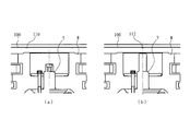
- FIG. 11B shows an example in which, in the example shown in FIG. 4A, the shape of the protective net 100 that comes into contact is a shape (108) (non-net portion) in which four sides of a substantially quadrangle are depressed inward. It is the figure shown. As shown in FIG.
- the shape of the hole may be a polygonal shape or a corrugated shape.
- FIG. 12A is a diagram showing an example in which the contact protrusion 110 is provided at a portion that comes into contact with the rotor 8 when the protective net 100 is deformed.
- FIG. 12B is a diagram showing an example in which the contact protrusion 112 is provided at a position where the protective net 100 is in contact with the shaft 7 when the protective net 100 is deformed.
- the contact protrusions 110 and 112 are formed by deforming the protective net 100 using a mold or a tool.
- the contact protrusions 110 and 112 are provided on the protective net 100, when the protective net 100 is deformed, the rotating body and the contact protrusions 110 and 112 come into contact with each other, so that the protective net 100 is protected. It is possible to support 100 and prevent the protective net 100 from being caught.
- FIG. 13A is a diagram showing an example in which the welding protrusion 114 is provided at a portion that comes into contact with the rotor 8 when the protective net 100 is deformed.
- FIG. 13B is a diagram showing an example in which the welding protrusion 116 is provided at a portion that comes into contact with the shaft 7 when the protective net 100 is deformed.
- the welding projections 114 and 116 are formed by joining different parts from the protective net 100 by welding or the like. As described above, by providing the welding projections 114 and 116 on the protective net 100, when the protective net 100 is deformed, the rotating body and the welding projections 114 and 116 contact each other to support and protect the protective net 100. It is possible to prevent the net 100 from being caught.
- the example shown in the seventh embodiment may be used in combination with the process performed on the rotating body side of the vacuum pump 1 shown in the first embodiment, for example.
- FIG. 14 is a diagram showing in more detail the relationship between the protrusions 75 of the shaft 7 and the holes of the protective net 100 in the example shown in FIG. FIG. 14A shows the mesh of the protection network 100.
- FIG. 15 is an enlarged view of the portion indicated by A in FIG. The gap W between the protrusion 75 of the shaft 7 and the protective net 100 shown in FIG. 15 is set smaller than the mesh of the protective net 100.
- the embodiment and each modification of the present invention may be combined with each other as necessary.
- the mesh shape of the protective net 100 has been described above as a hexagonal shape, it is needless to say that the same effect can be obtained even if it is another polygonal shape or a round shape.
- the present invention can be variously modified without departing from the spirit of the present invention. And it goes without saying that the present invention extends to the modified one.
- Vacuum pump Casing (outer cylinder) 3 Base 4 Inlet 6 Exhaust 7 Shaft 8 Rotor 9 Rotor 10 Rotor Cylinder 20 Thread Groove Exhaust Element (Screw Groove Stator) 30 Fixed Blade 35 Fixed Blade Spacer 72, 74 Tip Part 82, 84 Contact Part 75, 76, 77 Projection Part 78, 79, Separate Member 85, 86 Projection Part 89 Separate Member 100 Protective Net 102, 104 Plane 110, 112 Contact Projection Part 114, 116 Welding protrusion 200 Intake flange 700 Stator column
Landscapes
- Engineering & Computer Science (AREA)
- Mechanical Engineering (AREA)
- General Engineering & Computer Science (AREA)
- Non-Positive Displacement Air Blowers (AREA)
Abstract
回転体が能動的に保護網を支えることで、両者の間隔を可能な限り近接させ、高さ(長さ)の低い真空ポンプを提供する。本発明の実施形態に係る真空ポンプ(1)では、回転体側(シャフト(7)又はロータ(8))に、保護網(100)が、圧力の変化や温度の変化などの理由により真空ポンプ(1)側に変形した(撓んだ)場合、能動的に保護網(100)を支える機構を設ける。すなわち、保護網(100)と回転体の間隔を開けて巻き込み防止を図るのではなく、両者をより近接させて、保護網(100)を能動的に支えることで、巻き込みを防止している。そのため、真空ポンプ(1)の高さ(長さ)をより低くすることができる。
Description
本発明は、真空ポンプの吸気口に設けられる保護網に関し、回転体と保護網の間に、両者が接触し、保護網を保持する部分を設け、例えば、真空ポンプ内で圧力に大きな変化が発生したときなどに、回転体による保護網の巻き込み防止に関する。
ターボ分子ポンプやねじ溝式ポンプなどの真空ポンプ1では、吸気口4側に、真空ポンプ1内に異物が混入することを防止するための保護網100が設けられている。
図16は、この保護網100及び保護網を吸気口4に設置したところを説明する図である。保護網100は、6角形の孔が格子状に多数設けられた形状をしており、6角形の互いに向かい合う辺との距離は約5mmである。この図に示すように、この保護網100を吸気口4に設置することで、真空ポンプ1の内部に、誤って異物が入り込んでしまうことを防止している。
なお、保護網100の網目の形状や大きさは上記に限定されず、想定される異物の大きさなどに応じて種々のタイプがある。
図16は、この保護網100及び保護網を吸気口4に設置したところを説明する図である。保護網100は、6角形の孔が格子状に多数設けられた形状をしており、6角形の互いに向かい合う辺との距離は約5mmである。この図に示すように、この保護網100を吸気口4に設置することで、真空ポンプ1の内部に、誤って異物が入り込んでしまうことを防止している。
なお、保護網100の網目の形状や大きさは上記に限定されず、想定される異物の大きさなどに応じて種々のタイプがある。
ところで、真空ポンプ1の動作中、何らかの事情により、内部の圧力や温度が変化することがある。このとき、保護網100は、圧力や温度変化の影響を受け、図に点線で示すように、中央部が真空ポンプ1の内部側に変形(撓む)することがある。真空ポンプ1のロータ8は、高速回転しているので、変形した保護網100と接触し、保護網100を巻き込んでしまう恐れがある。
ここで、保護網100の変形(撓み)をより少なくするには、保護網100自体の厚みを増し、より強固にすることが考えられる。しかしながら、保護網100の厚みを増すと、真空ポンプ1のコンダクタンスが低下し、真空ポンプ1の排気性能に悪影響を与えてしまうという問題があった。
よって、保護網100は、なるべく薄くしたいという真空ポンプ1の設計上の要求が存在していた。
ここで、保護網100の変形(撓み)をより少なくするには、保護網100自体の厚みを増し、より強固にすることが考えられる。しかしながら、保護網100の厚みを増すと、真空ポンプ1のコンダクタンスが低下し、真空ポンプ1の排気性能に悪影響を与えてしまうという問題があった。
よって、保護網100は、なるべく薄くしたいという真空ポンプ1の設計上の要求が存在していた。
そのため、図16に示す従来の技術では、保護網100の想定される最大撓み量Yを超える隙間X(X>Y)を保護網100と回転体(シャフト7又はロータ8)の間に設け、保護網100の巻き込み防止を図っていた。
また、保護網100の巻き込みを防止する技術については、従来より種々の提案がなされている。
また、保護網100の巻き込みを防止する技術については、従来より種々の提案がなされている。
特許文献1に開示されている真空ポンプでは、保護網を回転軸に近づくにつれて段階的に回転体との距離は大きくなるようにして、回転体による保護網の巻き込みを防止している。
しかしながら、従来技術に示すように、保護網100とロータ8の間に隙間Xを設けると、結果として真空ポンプ1自体の高さ(長さ)が、増してしまうこととなる。これは、真空ポンプの排気性能を落とさずに、可能な限りコンパクトな真空ポンプを求めるユーザーの要求に反することとなる。
そこで、本発明は、回転体が能動的に保護網を支えることで、両者の間隔を可能な限り近接させ、高さ(長さ)の低い真空ポンプを提供することを目的とする。
請求項1記載の本願発明では、吸気口が形成された外装体と、前記吸気口に設けられた保護網と、前記外装体内に、回転体を具備する気体移送機構とを備えた真空ポンプであって、前記保護網が変形した際、前記保護網が前記回転体に巻き込まれるのを防ぐ、巻き込み防止機構を備えたことを特徴とする真空ポンプを提供する。
請求項2記載の本願発明では、前記巻き込み防止機構は、前記保護網が変形した際、前記保護網と前記回転体との間に、両者を接触させて支持する接触支持構造であることを特徴とする請求項1に記載の真空ポンプを提供する。
請求項3記載の本願発明では、前記接触支持構造は、前記回転体の前記保護網と接触す る箇所に、接触時に抵抗の小さい形状を形成したことを特徴とする請求項2に記載の真空ポンプを提供する。
請求項4記載の本願発明では、前記接触時に抵抗の小さい形状を、前記回転体のシャフトに設けたことを特徴とする請求項3に記載の真空ポンプを提供する。
請求項5記載の本願発明では、前記接触時に抵抗の小さい形状を、前記回転体のロータに設けたことを特徴とする請求項3に記載の真空ポンプを提供する。
請求項6記載の本願発明では、前記保護網の前記回転体と接触する箇所に、前記形成された接触時に抵抗の小さい形状に対応した穴を設けたことを特徴とする請求項3、請求項4又は請求項5に記載の真空ポンプを提供する。
請求項7記載の本願発明では、前記保護網に設けた穴の形状を、前記回転体に形成された接触時に抵抗の小さい形状との接触箇所を減らす形状としたことを特徴とする請求項6に記載の真空ポンプを提供する。
請求項8記載の本願発明では、前記回転体に形成された接触時に抵抗の小さい形状に、摩擦係数を下げるためのコーティングを施したことを特徴とする請求項3から請求項7の何れか1項に記載の真空ポンプを提供する。
請求項9記載の本願発明では、前記保護網の前記回転体と接触する箇所に、前記形成された接触時に抵抗の小さい形状に対応した平面を設けたことを特徴とする請求項3、請求項4又は請求項5に記載の真空ポンプを提供する。
請求項10記載の本願発明では、前記保護網に設けた穴と、前記形成された接触時に抵抗の小さい形状との間隔を、前記保護網の網目より小さくしたことを特徴とする請求項6又は請求項7に記載の真空ポンプを提供する。
請求項11記載の本願発明では、前記巻き込み防止機構は、前記保護網の前記回転体と接触する部分に設けられた、地材を残した非網部であることを特徴とする請求項1に記載の真空ポンプを提供する。
請求項12記載の本願発明では、吸気口が形成された外装体と、前記外装体内に、回転体を具備する気体移送機構とを備えた真空ポンプにおいて、前記吸気口に設けられた保護網であって、変形した際、前記回転体によって、巻き込まれるのを防止する巻き込み防止構造を備えていることを特徴とする保護網を提供する。
請求項13記載の本願発明では、吸気口が形成された外装体と、前記吸気口に設けられた保護網と、前記外装体内に、回転体を具備する気体移送機構とを備えた真空ポンプに設置する接触部品であって、前記保護網が変形した際、前記回転体の前記保護網と接触する箇所に設置され、接触時に抵抗の小さい形状の接触部品を提供する。
請求項2記載の本願発明では、前記巻き込み防止機構は、前記保護網が変形した際、前記保護網と前記回転体との間に、両者を接触させて支持する接触支持構造であることを特徴とする請求項1に記載の真空ポンプを提供する。
請求項3記載の本願発明では、前記接触支持構造は、前記回転体の前記保護網と接触す る箇所に、接触時に抵抗の小さい形状を形成したことを特徴とする請求項2に記載の真空ポンプを提供する。
請求項4記載の本願発明では、前記接触時に抵抗の小さい形状を、前記回転体のシャフトに設けたことを特徴とする請求項3に記載の真空ポンプを提供する。
請求項5記載の本願発明では、前記接触時に抵抗の小さい形状を、前記回転体のロータに設けたことを特徴とする請求項3に記載の真空ポンプを提供する。
請求項6記載の本願発明では、前記保護網の前記回転体と接触する箇所に、前記形成された接触時に抵抗の小さい形状に対応した穴を設けたことを特徴とする請求項3、請求項4又は請求項5に記載の真空ポンプを提供する。
請求項7記載の本願発明では、前記保護網に設けた穴の形状を、前記回転体に形成された接触時に抵抗の小さい形状との接触箇所を減らす形状としたことを特徴とする請求項6に記載の真空ポンプを提供する。
請求項8記載の本願発明では、前記回転体に形成された接触時に抵抗の小さい形状に、摩擦係数を下げるためのコーティングを施したことを特徴とする請求項3から請求項7の何れか1項に記載の真空ポンプを提供する。
請求項9記載の本願発明では、前記保護網の前記回転体と接触する箇所に、前記形成された接触時に抵抗の小さい形状に対応した平面を設けたことを特徴とする請求項3、請求項4又は請求項5に記載の真空ポンプを提供する。
請求項10記載の本願発明では、前記保護網に設けた穴と、前記形成された接触時に抵抗の小さい形状との間隔を、前記保護網の網目より小さくしたことを特徴とする請求項6又は請求項7に記載の真空ポンプを提供する。
請求項11記載の本願発明では、前記巻き込み防止機構は、前記保護網の前記回転体と接触する部分に設けられた、地材を残した非網部であることを特徴とする請求項1に記載の真空ポンプを提供する。
請求項12記載の本願発明では、吸気口が形成された外装体と、前記外装体内に、回転体を具備する気体移送機構とを備えた真空ポンプにおいて、前記吸気口に設けられた保護網であって、変形した際、前記回転体によって、巻き込まれるのを防止する巻き込み防止構造を備えていることを特徴とする保護網を提供する。
請求項13記載の本願発明では、吸気口が形成された外装体と、前記吸気口に設けられた保護網と、前記外装体内に、回転体を具備する気体移送機構とを備えた真空ポンプに設置する接触部品であって、前記保護網が変形した際、前記回転体の前記保護網と接触する箇所に設置され、接触時に抵抗の小さい形状の接触部品を提供する。
本発明によれば、回転体側から能動的に保護網を支えることにより、保護網の巻き込みを防止し、両者の間隔をより狭くすることができ、結果として、真空ポンプの高さを低くすることができる。
(i)実施形態の概要
本発明の実施形態に係る真空ポンプ1では、回転体(シャフト7又はロータ8)に、保護網100が、圧力の変化や温度の変化などの理由により真空ポンプ1側に変形した(撓んだ)場合、能動的に保護網100を支える機構を設ける。
すなわち、保護網100と回転体の間隔を開けて巻き込み防止を図るのではなく、両者をより近接させて、保護網100を能動的に支えることで、巻き込みを防止している。そのため、真空ポンプ1の高さ(長さ)をより低くすることができる。
また、保護網100側にも巻き込み防止の機構を設けるようにしてもよい。
本発明の実施形態に係る真空ポンプ1では、回転体(シャフト7又はロータ8)に、保護網100が、圧力の変化や温度の変化などの理由により真空ポンプ1側に変形した(撓んだ)場合、能動的に保護網100を支える機構を設ける。
すなわち、保護網100と回転体の間隔を開けて巻き込み防止を図るのではなく、両者をより近接させて、保護網100を能動的に支えることで、巻き込みを防止している。そのため、真空ポンプ1の高さ(長さ)をより低くすることができる。
また、保護網100側にも巻き込み防止の機構を設けるようにしてもよい。
(ii)実施形態の詳細
以下、本発明の好適な実施の形態について、図1から図15を参照して詳細に説明する。
(真空ポンプ1の構成)
図1は、本発明の第1実施形態に係る真空ポンプ1の概略構成例を示した図であり、真空ポンプ1の軸線方向の断面図を示している。
なお、本発明の実施形態では、便宜上、回転翼の直径方向を「径(直径・半径)方向」、回転翼の直径方向と垂直な方向を「軸線方向(または軸方向)」として説明する。
真空ポンプ1の外装体を形成するケーシング(外筒/筐体)2は、略円筒状の形状をしており、ケーシング2の下部(排気口6側)に設けられたベース3と共に真空ポンプ1の筐体を構成している。そして、この筐体の内部には、真空ポンプ1に排気機能を発揮させる構造物である気体移送機構が収納されている。
本実施形態では、この気体移送機構は、回転自在に支持された回転体(ロータ8、回転翼9/ロータ円筒部10など)と、筐体に対して固定されたステータ部(固定翼30/ねじ溝排気要素20など)から構成されている。
また、図示しないが、真空ポンプ1の外装体の外部には、真空ポンプ1の動作を制御する制御装置が専用線を介して接続されている。
以下、本発明の好適な実施の形態について、図1から図15を参照して詳細に説明する。
(真空ポンプ1の構成)
図1は、本発明の第1実施形態に係る真空ポンプ1の概略構成例を示した図であり、真空ポンプ1の軸線方向の断面図を示している。
なお、本発明の実施形態では、便宜上、回転翼の直径方向を「径(直径・半径)方向」、回転翼の直径方向と垂直な方向を「軸線方向(または軸方向)」として説明する。
真空ポンプ1の外装体を形成するケーシング(外筒/筐体)2は、略円筒状の形状をしており、ケーシング2の下部(排気口6側)に設けられたベース3と共に真空ポンプ1の筐体を構成している。そして、この筐体の内部には、真空ポンプ1に排気機能を発揮させる構造物である気体移送機構が収納されている。
本実施形態では、この気体移送機構は、回転自在に支持された回転体(ロータ8、回転翼9/ロータ円筒部10など)と、筐体に対して固定されたステータ部(固定翼30/ねじ溝排気要素20など)から構成されている。
また、図示しないが、真空ポンプ1の外装体の外部には、真空ポンプ1の動作を制御する制御装置が専用線を介して接続されている。
ケーシング2の端部には、当該真空ポンプ1へ気体を導入するための吸気口4が形成されている。また、ケーシング2の吸気口4側の端面には、外周側へ張り出した吸気口フランジ200が形成されている。
この吸気口4の下部には、真空ポンプ1内に、異物が入り込むのを防止するための保護網100が設けられている。この保護網100は、ボルト又はスナップリングにより、ケーシング2に固定されている。
また、真空ポンプ1の下流側には、当該真空ポンプ1から気体を排気するための排気口6が形成されている。
この吸気口4の下部には、真空ポンプ1内に、異物が入り込むのを防止するための保護網100が設けられている。この保護網100は、ボルト又はスナップリングにより、ケーシング2に固定されている。
また、真空ポンプ1の下流側には、当該真空ポンプ1から気体を排気するための排気口6が形成されている。
回転体は、回転軸であるシャフト7、このシャフト7に配設されたロータ8、ロータ8に設けられた複数枚の回転翼9、排気口6側に設けられたロータ円筒部(スカート部)10を備えている。
各回転翼9は、シャフト7の軸線に対して垂直に放射状に伸びた部材により構成される。
また、ロータ円筒部10は、ロータ8の回転軸線と同心の円筒形状をした円筒部材により構成される。
各回転翼9は、シャフト7の軸線に対して垂直に放射状に伸びた部材により構成される。
また、ロータ円筒部10は、ロータ8の回転軸線と同心の円筒形状をした円筒部材により構成される。
ステータコラム700内には、詳細は図示しないが、シャフト7の軸線方向中程には、シャフト7を高速回転させるためのモータ部が設けられている。また、当該モータ部に対して吸気口4側と排気口6側には、シャフト7をラジアル方向(径方向)に非接触で支持するための径方向磁気軸受装置が設けられている。さらに、シャフト7の下端には、シャフト7をアキシャル方向(軸線方向)に非接触で支持するための軸方向磁気軸受装置が設けられている。
ケーシング(筐体)2の内周側には、固定翼30が形成されている。そして、固定翼30は円筒形状をした固定翼スペーサ35により互いに隔てられて固定されている。
なお、回転翼9と固定翼30は互い違いに配置され、軸線方向に複数段形成されるが、真空ポンプ1に要求される排出性能を満たすために、必要に応じて任意の数のロータ部品およびステータ部品を設けることができる。
なお、回転翼9と固定翼30は互い違いに配置され、軸線方向に複数段形成されるが、真空ポンプ1に要求される排出性能を満たすために、必要に応じて任意の数のロータ部品およびステータ部品を設けることができる。
本実施形態に係る真空ポンプ1では、排気口6側にねじ溝排気要素20(ねじ溝型排気機構)が配設される。ねじ溝排気要素20のロータ円筒部10との対向面には、ねじ溝(らせん溝)が形成されている。あるいは、ロータ円筒部10のねじ溝排気要素20との対向面にねじ溝が形成される構成であってもよい。
ねじ溝排気要素20におけるロータ円筒部10との対向面側(すなわち、真空ポンプ1の軸線に平行な内周面)は、所定のクリアランスを隔ててロータ円筒部10の外周面と対向しており、ロータ円筒部10が高速回転すると、真空ポンプ1で圧縮されたガスがロータ円筒部10の回転に伴ってねじ溝にガイドされながら排気口6側へ送出されるようになっている。すなわち、ねじ溝は、ガスを輸送する流路となっている。
ねじ溝排気要素20におけるロータ円筒部10との対向面側(すなわち、真空ポンプ1の軸線に平行な内周面)は、所定のクリアランスを隔ててロータ円筒部10の外周面と対向しており、ロータ円筒部10が高速回転すると、真空ポンプ1で圧縮されたガスがロータ円筒部10の回転に伴ってねじ溝にガイドされながら排気口6側へ送出されるようになっている。すなわち、ねじ溝は、ガスを輸送する流路となっている。
このように、ねじ溝排気要素20におけるロータ円筒部10との対向面と、ロータ円筒部10とが、所定のクリアランスを隔てて対向することにより、ねじ溝排気要素20の軸線方向側内周面に形成されたねじ溝でガスを移送する気体移送機構を構成している。
なお、ガスが吸気口4側へ逆流する力を低減させるために、このクリアランスは小さければ小さいほど好ましい。
また、ねじ溝排気要素20に形成されたらせん溝の方向は、らせん溝内をロータ8の回転方向にガスが輸送された場合、排気口6に向かう方向である。
そして、らせん溝の深さは、排気口6に近づくにつれて次第に浅くなるようになっており、らせん溝を輸送されるガスは排気口6に近づくにつれて徐々に圧縮されるようになっている。
上述した構成により、真空ポンプ1は、当該真空ポンプ1が固定(配設)される装置内の真空排気処理を行うことができる。
なお、ガスが吸気口4側へ逆流する力を低減させるために、このクリアランスは小さければ小さいほど好ましい。
また、ねじ溝排気要素20に形成されたらせん溝の方向は、らせん溝内をロータ8の回転方向にガスが輸送された場合、排気口6に向かう方向である。
そして、らせん溝の深さは、排気口6に近づくにつれて次第に浅くなるようになっており、らせん溝を輸送されるガスは排気口6に近づくにつれて徐々に圧縮されるようになっている。
上述した構成により、真空ポンプ1は、当該真空ポンプ1が固定(配設)される装置内の真空排気処理を行うことができる。
(実施形態1:回転体(シャフト7又はロータ8)の接触箇所を抵抗の小さい形状とする実施形態)
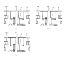
図2は、シャフト7の保護網100との接触箇所を抵抗の小さい形状とする実施形態を説明するための図である。
図2に示す実施形態では、保護網100が変形し、シャフト7と接触する際、接触するシャフト7の先端部を抵抗の小さい形状とし、保護網100を支えて、巻き込みを防止している。
図2(a)では、シャフト7の先端部72を球状にしている。図2(b)では、シャフト7の先端部74をR面取り形状にしている。
図2は、シャフト7の保護網100との接触箇所を抵抗の小さい形状とする実施形態を説明するための図である。
図2に示す実施形態では、保護網100が変形し、シャフト7と接触する際、接触するシャフト7の先端部を抵抗の小さい形状とし、保護網100を支えて、巻き込みを防止している。
図2(a)では、シャフト7の先端部72を球状にしている。図2(b)では、シャフト7の先端部74をR面取り形状にしている。
図3は、ロータ8の保護網100との接触箇所を抵抗の小さい形状とする実施形態を説明するための図である。
図3に示す実施形態では、保護網100が変形し、ロータ8と接触する際、ロータ8の接触部分を抵抗の小さい形状とし、保護網100を支えて、巻き込みを防止している。
図3(a)では、ロータ8の接触部82を球状にしている。図3(b)では、ロータ8の接触部84をR面取り型にしている。このような形状を形成するには、ロータ8を加工してもよいが、当該形状のリング状の部材をロータ8に取り付けることで形成してもよい。
図3に示す実施形態では、保護網100が変形し、ロータ8と接触する際、ロータ8の接触部分を抵抗の小さい形状とし、保護網100を支えて、巻き込みを防止している。
図3(a)では、ロータ8の接触部82を球状にしている。図3(b)では、ロータ8の接触部84をR面取り型にしている。このような形状を形成するには、ロータ8を加工してもよいが、当該形状のリング状の部材をロータ8に取り付けることで形成してもよい。
(実施形態2:保護網100に穴を開け、回転体に接触して支える形状を設けた実施形態)
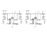
図4は、保護網100に穴を開け、回転体に接触して支える形状を設けた実施形態を説明するための図である。
この実施形態では、保護網100のシャフト7の突起部75又はロータ8の突起部85に接触する箇所に予め穴を開けておき、保護網100が変形すると、保護網100の穴と直ちにシャフト7の突起部75又はロータ8の突起部85が接触し、保護網100の変形を支える。
図4(a)は、シャフト7にテーパー状の突起部75を設け、保護網100の穴に接触させて支える例を示した図である。
図4(b)は、ロータ8にテーパー状の突起部85を設け、保護網100の穴に接触させて支える例を示した図である。
このような形状を形成するには、ロータ8を加工してもよいが、当該形状のリング状の部材をロータ8に取り付けることで形成してもよい。
この実施形態では保護網100と回転体をより近接させることができるので、更に真空ポンプの高さ(長さ)を低くすることができる。
この実施形態では、保護網100と回転体の隙間を10mm程度短縮することができる。よって、真空ポンプ1の高さが350mmであった場合、高さを340mmとすることができる。
図4は、保護網100に穴を開け、回転体に接触して支える形状を設けた実施形態を説明するための図である。
この実施形態では、保護網100のシャフト7の突起部75又はロータ8の突起部85に接触する箇所に予め穴を開けておき、保護網100が変形すると、保護網100の穴と直ちにシャフト7の突起部75又はロータ8の突起部85が接触し、保護網100の変形を支える。
図4(a)は、シャフト7にテーパー状の突起部75を設け、保護網100の穴に接触させて支える例を示した図である。
図4(b)は、ロータ8にテーパー状の突起部85を設け、保護網100の穴に接触させて支える例を示した図である。
このような形状を形成するには、ロータ8を加工してもよいが、当該形状のリング状の部材をロータ8に取り付けることで形成してもよい。
この実施形態では保護網100と回転体をより近接させることができるので、更に真空ポンプの高さ(長さ)を低くすることができる。
この実施形態では、保護網100と回転体の隙間を10mm程度短縮することができる。よって、真空ポンプ1の高さが350mmであった場合、高さを340mmとすることができる。
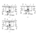
図5は、実施形態2において、シャフト7の突起部(先端)の形状を保護網100と接触した際、抵抗が小さくなるような形状とした例を示した図である。
図5(a)は、シャフト7の突起部75をテーパー形状として、保護網100の穴と接触した際、両者間の抵抗を軽減し、シャフト7で保護網100を支え、巻き込みを防止している。
図5(b)は、シャフト7の突起部76を球状の形状として、保護網100の穴と接触した際、両者間の抵抗を軽減し、シャフト7で保護網100を支え、巻き込みを防止している。
図5(c)は、シャフト7の突起部77をR面取り形状として、保護網100の穴と接触した際、両者間の抵抗を軽減し、シャフト7で保護網100を支え、巻き込みを防止している。
図5(a)は、シャフト7の突起部75をテーパー形状として、保護網100の穴と接触した際、両者間の抵抗を軽減し、シャフト7で保護網100を支え、巻き込みを防止している。
図5(b)は、シャフト7の突起部76を球状の形状として、保護網100の穴と接触した際、両者間の抵抗を軽減し、シャフト7で保護網100を支え、巻き込みを防止している。
図5(c)は、シャフト7の突起部77をR面取り形状として、保護網100の穴と接触した際、両者間の抵抗を軽減し、シャフト7で保護網100を支え、巻き込みを防止している。
図6は、実施形態2において、ロータ8の突起部の形状を保護網100と接触した際、抵抗が小さくなるような形状とした例を示した図である。
図6(a)は、ロータ8の突起部85をテーパー形状として、保護網100の穴と接触した際、両者間の抵抗を軽減し、ロータ8で保護網100を支え、巻き込みを防止している。
図6(b)は、ロータ8の突起部86をR面取り形状として、保護網100の穴と接触した際、両者間の抵抗を軽減し、ロータ8で保護網100を支え、巻き込みを防止している。
図6(a)は、ロータ8の突起部85をテーパー形状として、保護網100の穴と接触した際、両者間の抵抗を軽減し、ロータ8で保護網100を支え、巻き込みを防止している。
図6(b)は、ロータ8の突起部86をR面取り形状として、保護網100の穴と接触した際、両者間の抵抗を軽減し、ロータ8で保護網100を支え、巻き込みを防止している。
(実施形態3:実施形態1及び実施形態2において、回転体の接触箇所(接触部及び突起部)を別部材で構成する実施形態)
図7は、実施形態1の回転体の接触箇所(接触部)及び実施形態2の接触箇所(突起部)を別部材で構成する実施形態を説明する図である。
図7(a)は、図2(a)に示した実施形態1のシャフト7の先端部72(一体形成)を別部材78で構成した例を示した図である。
図7(b)は、図4(a)に示した実施形態2のシャフト7の突起部75(一体形成)を別部材79で構成した例を示した図である。
図7(c)は、図3(a)に示した実施形態1のロータ8の接触部82(一体形成)を別部材89で構成した例を示した図である。
このように、回転体の先端部又突起部を別部材で構成することで、従来製品への後付けで本発明を実施できるという効果がある。
図7は、実施形態1の回転体の接触箇所(接触部)及び実施形態2の接触箇所(突起部)を別部材で構成する実施形態を説明する図である。
図7(a)は、図2(a)に示した実施形態1のシャフト7の先端部72(一体形成)を別部材78で構成した例を示した図である。
図7(b)は、図4(a)に示した実施形態2のシャフト7の突起部75(一体形成)を別部材79で構成した例を示した図である。
図7(c)は、図3(a)に示した実施形態1のロータ8の接触部82(一体形成)を別部材89で構成した例を示した図である。
このように、回転体の先端部又突起部を別部材で構成することで、従来製品への後付けで本発明を実施できるという効果がある。
(実施形態4:実施形態1から実施形態3において、保護網100と接触する部分に摩擦係数を下げる処理を行う実施形態)
図8(a)は、実施形態1の図2(a)で示した例において、シャフト7の先端部72にコーティングを施して、接触時の摩擦係数を下げた例を示した図である。このコーティングの例としては、メッキ、PVD(Physical vapor deposition)コーティング、CVD(Chemical vapor deposition)コーティングなどがあげられる。
図8(b)は、実施形態2の図5(a)で示した例において、シャフト7の突起部75にコーティングを施して、接触時の摩擦係数を下げた例を示した図である。
このように、接触時の摩擦係数を下げることで、両者の接触時に滑り易くなり、より保護網100の巻き込みを防止できる。
上記の例では、接触部分にコーティングを施す例を示したが、接触部分に焼き入れを施して硬度を上げることで、より保護網100の巻き込みを防止するようにしてもよい。
なお、保護網100の接触部分にコーティング施すようにしてもよい。また、シャフト7の突起部75および保護網100の接触部分双方にコーティング施すようにしてもよい。
図8(a)は、実施形態1の図2(a)で示した例において、シャフト7の先端部72にコーティングを施して、接触時の摩擦係数を下げた例を示した図である。このコーティングの例としては、メッキ、PVD(Physical vapor deposition)コーティング、CVD(Chemical vapor deposition)コーティングなどがあげられる。
図8(b)は、実施形態2の図5(a)で示した例において、シャフト7の突起部75にコーティングを施して、接触時の摩擦係数を下げた例を示した図である。
このように、接触時の摩擦係数を下げることで、両者の接触時に滑り易くなり、より保護網100の巻き込みを防止できる。
上記の例では、接触部分にコーティングを施す例を示したが、接触部分に焼き入れを施して硬度を上げることで、より保護網100の巻き込みを防止するようにしてもよい。
なお、保護網100の接触部分にコーティング施すようにしてもよい。また、シャフト7の突起部75および保護網100の接触部分双方にコーティング施すようにしてもよい。
(実施形態5:保護網100の接触部分を平面とする実施形態)
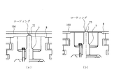
図9は、実施形態1の図2(a)に示した例において、更に保護網100にシャフト7の先端部72と接触する部分を平面102とした例を示した図である。
ここで、平面とするとは、保護網100の6角形の網目を形成せず、地材をそのまま残すことを意味する(非網部)。
図9(a)に示す例では、シャフト7の先端部72と接触する箇所に6角形の網目を形成せず、地材を残して平面102としている(非網部)。
このように、保護網100の接触する部分に平面102を設けることで、より保護網100の巻き込みを防止できる。
図9は、実施形態1の図2(a)に示した例において、更に保護網100にシャフト7の先端部72と接触する部分を平面102とした例を示した図である。
ここで、平面とするとは、保護網100の6角形の網目を形成せず、地材をそのまま残すことを意味する(非網部)。
図9(a)に示す例では、シャフト7の先端部72と接触する箇所に6角形の網目を形成せず、地材を残して平面102としている(非網部)。
このように、保護網100の接触する部分に平面102を設けることで、より保護網100の巻き込みを防止できる。
図10は、実施形態1の図3(a)に示した例において、更に保護網100にロータ8の先端部82と接触する部分を平面104とした例を示した図である。
図10(a)に示す例では、ロータ8の先端部82と接触する箇所に6角形の網目を形成せず、地材を残して平面104としている(非網部)。この平面104は、ロータ8(先端部82)の回転に対応して、円周状になっている。
このように、保護網100の接触する部分に平面104を設けることで、より保護網100の巻き込みを防止できる。
図10(a)に示す例では、ロータ8の先端部82と接触する箇所に6角形の網目を形成せず、地材を残して平面104としている(非網部)。この平面104は、ロータ8(先端部82)の回転に対応して、円周状になっている。
このように、保護網100の接触する部分に平面104を設けることで、より保護網100の巻き込みを防止できる。
(実施形態6:実施形態2において、接触する保護網100側の穴の形状を接触箇所を減らす形状とする実施形態)
図11(a)は、図4(a)に示した例において、接触する保護網100側の形状を略四角形(106)(非網部)とした例を示した図である。
図11(b)は、図4(a)に示した例において、接触する保護網100側の形状を略四角形の4辺が内側へ窪んだ形状(108)(非網部)とした例を示した図である。
図11に示すように、保護網100に接触するシャフト7の突起部75が、水平断面の形状が円形であるので、接触する保護網100側の形状を円形でない形状とすることで、円形とした場合に比べて、接触箇所を減らすことができ、より保護網100の巻き込みを防止できる。
穴の形状としては、多角形や円形を波形化した形状でもよい。
図11(a)は、図4(a)に示した例において、接触する保護網100側の形状を略四角形(106)(非網部)とした例を示した図である。
図11(b)は、図4(a)に示した例において、接触する保護網100側の形状を略四角形の4辺が内側へ窪んだ形状(108)(非網部)とした例を示した図である。
図11に示すように、保護網100に接触するシャフト7の突起部75が、水平断面の形状が円形であるので、接触する保護網100側の形状を円形でない形状とすることで、円形とした場合に比べて、接触箇所を減らすことができ、より保護網100の巻き込みを防止できる。
穴の形状としては、多角形や円形を波形化した形状でもよい。
((実施形態7:保護網100側に、保護網100の変形時に回転体と接触する部分を設けた実施形態)
図12(a)は、保護網100が変形した際、ロータ8と接触する箇所に接触突起部110を設けた例を示した図である。
図12(b)は、保護網100が変形した際、シャフト7と接触する箇所に接触突起部112を設けた例を示した図である。
この接触突起部110、112は、型や工具等を用いて、保護網100を変形させることで形成する。
このように、保護網100に接触突起部110、112(非網部)を設けることで、保護網100が変形したときに、回転体と接触突起部110、112が接触することで、保護網100を支え、保護網100の巻き込みを防止できる。
図12(a)は、保護網100が変形した際、ロータ8と接触する箇所に接触突起部110を設けた例を示した図である。
図12(b)は、保護網100が変形した際、シャフト7と接触する箇所に接触突起部112を設けた例を示した図である。
この接触突起部110、112は、型や工具等を用いて、保護網100を変形させることで形成する。
このように、保護網100に接触突起部110、112(非網部)を設けることで、保護網100が変形したときに、回転体と接触突起部110、112が接触することで、保護網100を支え、保護網100の巻き込みを防止できる。
図13(a)は、保護網100が変形した際、ロータ8と接触する箇所に溶接突起部114を設けた例を示した図である。
図13(b)は、保護網100が変形した際、シャフト7と接触する箇所に溶接突起部116を設けた例を示した図である。
この溶接突起部114、116(非網部)は、保護網100とは、別部品を溶接等で接合させて形成する。
このように、保護網100に溶接突起部114、116を設けることで、保護網100が変形したときに、回転体と溶接突起部114、116が接触することで、保護網100を支え、保護網100の巻き込みを防止できる。
この実施形態7に示す例は、例えば実施形態1に示す真空ポンプ1の回転体側に施す処理と併用してもよい。
図13(b)は、保護網100が変形した際、シャフト7と接触する箇所に溶接突起部116を設けた例を示した図である。
この溶接突起部114、116(非網部)は、保護網100とは、別部品を溶接等で接合させて形成する。
このように、保護網100に溶接突起部114、116を設けることで、保護網100が変形したときに、回転体と溶接突起部114、116が接触することで、保護網100を支え、保護網100の巻き込みを防止できる。
この実施形態7に示す例は、例えば実施形態1に示す真空ポンプ1の回転体側に施す処理と併用してもよい。
(実施形態8:実施形態2において、保護網100に穴を開ける際、保護網100の穴とシャフト7の突起部75又はロータ8の突起部85との間隔を保護網100の網目より小さくする実施形態)
図14は、図5(a)に示した例のシャフト7の突起部75と保護網100の穴との関係をより詳細に示した図である。図14(a)は、保護網100の網目を示している。
図15は、図14のAで示した箇所の拡大図である。
図15に示す、シャフト7の突起部75と保護網100との間隔Wを保護網100の網目より小さく設定する。
こうすることで、保護網100に穴を開けても、異物が混入することを防止できる。すなわち、全体に保護網100が存在するのと同様の効果を得ることができる。
図14は、図5(a)に示した例のシャフト7の突起部75と保護網100の穴との関係をより詳細に示した図である。図14(a)は、保護網100の網目を示している。
図15は、図14のAで示した箇所の拡大図である。
図15に示す、シャフト7の突起部75と保護網100との間隔Wを保護網100の網目より小さく設定する。
こうすることで、保護網100に穴を開けても、異物が混入することを防止できる。すなわち、全体に保護網100が存在するのと同様の効果を得ることができる。
なお、本発明の実施形態および各変形例は、必要に応じて各々を組み合わせる構成にしてもよい。
以上、保護網100の網目の形状は、6角形のものとして説明したが、これに限定されず、他の多角形や丸形のものであっても同様の効果を得ることは言うまでもない。
以上、保護網100の網目の形状は、6角形のものとして説明したが、これに限定されず、他の多角形や丸形のものであっても同様の効果を得ることは言うまでもない。
また、本発明は、本発明の精神を逸脱しない限り種々の改変をなすことができる。そして、本発明が当該改変されたものに及ぶことは当然である。
1 真空ポンプ
2 ケーシング(外筒)
3 ベース
4 吸気口
6 排気口
7 シャフト
8 ロータ
9 回転翼
10 ロータ円筒部
20 ねじ溝排気要素(ねじ溝ステータ)
30 固定翼
35 固定翼スペーサ
72、74 先端部
82、84 接触部
75、76、77 突起部
78、79、 別部材
85、86 突起部
89 別部材
100 保護網
102、104 平面
110、112 接触突起部
114、116 溶接突起部
200 吸気口フランジ
700 ステータコラム
2 ケーシング(外筒)
3 ベース
4 吸気口
6 排気口
7 シャフト
8 ロータ
9 回転翼
10 ロータ円筒部
20 ねじ溝排気要素(ねじ溝ステータ)
30 固定翼
35 固定翼スペーサ
72、74 先端部
82、84 接触部
75、76、77 突起部
78、79、 別部材
85、86 突起部
89 別部材
100 保護網
102、104 平面
110、112 接触突起部
114、116 溶接突起部
200 吸気口フランジ
700 ステータコラム
Claims (13)
- 吸気口が形成された外装体と、
前記吸気口に設けられた保護網と、
前記外装体内に、回転体を具備する気体移送機構とを備えた真空ポンプであって、
前記保護網が変形した際、前記保護網が前記回転体に巻き込まれるのを防ぐ、巻き込み防止機構を備えたことを特徴とする真空ポンプ。
- 前記巻き込み防止機構は、前記保護網が変形した際、前記保護網と前記回転体との間に、両者を接触させて支持する接触支持構造であることを特徴とする請求項1に記載の真空ポンプ。
- 前記接触支持構造は、前記回転体の前記保護網と接触する箇所に、接触時に抵抗の小さい形状を形成したことを特徴とする請求項2に記載の真空ポンプ。
- 前記接触時に抵抗の小さい形状を、前記回転体のシャフトに設けたことを特徴とする請求項3に記載の真空ポンプ。
- 前記接触時に抵抗の小さい形状を、前記回転体のロータに設けたことを特徴とする請求項3に記載の真空ポンプ。
- 前記保護網の前記回転体と接触する箇所に、前記形成された接触時に抵抗の小さい形状に対応した穴を設けたことを特徴とする請求項3、請求項4又は請求項5に記載の真空ポンプ。
- 前記保護網に設けた穴の形状を、前記回転体に形成された接触時に抵抗の小さい形状の接触箇所を減らす形状としたことを特徴とする請求項6に記載の真空ポンプ。
- 前記回転体に形成された接触時に抵抗の小さい形状に、摩擦係数を下げるためのコーティングを施したことを特徴とする請求項3から請求項7の何れか1項に記載の真空ポンプ。
- 前記保護網の前記回転体と接触する箇所に、前記形成された接触時に抵抗の小さい形状に対応した平面を設けたことを特徴とする請求項3、請求項4又は請求項5に記載の真空ポンプ。
- 前記保護網に設けた穴と、前記形成された接触時に抵抗の小さい形状との間隔を、前記保護網の網目より小さくしたことを特徴とする請求項6又は請求項7に記載の真空ポンプ。
- 前記巻き込み防止機構は、前記保護網の前記回転体と接触する部分に設けられた、地材を残した非網部であることを特徴とする請求項1に記載の真空ポンプ。
- 吸気口が形成された外装体と、
前記外装体内に、回転体を具備する気体移送機構とを備えた真空ポンプにおいて、
前記吸気口に設けられた保護網であって、
変形した際、前記回転体によって、巻き込まれるのを防止する巻き込み防止構造を備えていることを特徴とする保護網。
- 吸気口が形成された外装体と、
前記吸気口に設けられた保護網と、
前記外装体内に、回転体を具備する気体移送機構とを備えた真空ポンプに設置する接触部品であって、
前記保護網が変形した際、前記回転体の前記保護網と接触する箇所に設置され、接触時に抵抗の小さい形状の接触部品。
Priority Applications (3)
| Application Number | Priority Date | Filing Date | Title |
|---|---|---|---|
| CN201980068956.6A CN112840130B (zh) | 2018-10-31 | 2019-10-24 | 真空泵、保护网及接触零件 |
| US17/287,301 US20210355966A1 (en) | 2018-10-31 | 2019-10-24 | Vacuum pump, protective net, and contact part |
| US18/916,075 US20250035116A1 (en) | 2018-10-31 | 2024-10-15 | Vacuum pump, protective net, and contact part |
Applications Claiming Priority (2)
| Application Number | Priority Date | Filing Date | Title |
|---|---|---|---|
| JP2018204847A JP7289627B2 (ja) | 2018-10-31 | 2018-10-31 | 真空ポンプ、保護網及び接触部品 |
| JP2018-204847 | 2018-10-31 |
Related Child Applications (2)
| Application Number | Title | Priority Date | Filing Date |
|---|---|---|---|
| US17/287,301 A-371-Of-International US20210355966A1 (en) | 2018-10-31 | 2019-10-24 | Vacuum pump, protective net, and contact part |
| US18/916,075 Division US20250035116A1 (en) | 2018-10-31 | 2024-10-15 | Vacuum pump, protective net, and contact part |
Publications (1)
| Publication Number | Publication Date |
|---|---|
| WO2020090633A1 true WO2020090633A1 (ja) | 2020-05-07 |
Family
ID=70464098
Family Applications (1)
| Application Number | Title | Priority Date | Filing Date |
|---|---|---|---|
| PCT/JP2019/041795 Ceased WO2020090633A1 (ja) | 2018-10-31 | 2019-10-24 | 真空ポンプ、保護網及び接触部品 |
Country Status (4)
| Country | Link |
|---|---|
| US (2) | US20210355966A1 (ja) |
| JP (1) | JP7289627B2 (ja) |
| CN (1) | CN112840130B (ja) |
| WO (1) | WO2020090633A1 (ja) |
Families Citing this family (1)
| Publication number | Priority date | Publication date | Assignee | Title |
|---|---|---|---|---|
| FR3164758A1 (fr) * | 2024-07-22 | 2026-01-23 | Pfeiffer Vacuum | Pompe à vide turbomoléculaire et procédé de montage d’un filtre pare-éclat |
Citations (3)
| Publication number | Priority date | Publication date | Assignee | Title |
|---|---|---|---|---|
| JPH02196192A (ja) * | 1989-01-24 | 1990-08-02 | Matsushita Seiko Co Ltd | 扇風機 |
| JP2001059496A (ja) * | 1999-06-14 | 2001-03-06 | Ebara Corp | ターボ分子ポンプ |
| WO2008139614A1 (ja) * | 2007-05-14 | 2008-11-20 | Shimadzu Corporation | 真空ポンプ |
Family Cites Families (19)
| Publication number | Priority date | Publication date | Assignee | Title |
|---|---|---|---|---|
| JPH0343551Y2 (ja) * | 1988-02-16 | 1991-09-12 | ||
| JPH03222895A (ja) * | 1990-01-26 | 1991-10-01 | Hitachi Koki Co Ltd | ねじ溝真空ポンプ |
| JP2978339B2 (ja) * | 1992-09-21 | 1999-11-15 | 株式会社日立製作所 | 真空ポンプ |
| JPH0975643A (ja) * | 1995-09-07 | 1997-03-25 | Duskin Co Ltd | 換気扇用フィルタ装着具、および換気扇へのフィルタ装着方法 |
| DE19804768B4 (de) * | 1998-02-06 | 2006-08-24 | Pfeiffer Vacuum Gmbh | Rotorlagerung für eine Gasreibungspumpe |
| JPH11247790A (ja) * | 1998-03-04 | 1999-09-14 | Shimadzu Corp | 真空ポンプ |
| US20030017047A1 (en) * | 1998-06-25 | 2003-01-23 | Ebara Corporation | Turbo-molecular pump |
| JP4504102B2 (ja) * | 2004-05-31 | 2010-07-14 | 株式会社大阪真空機器製作所 | 分子ポンプ |
| DE102005052792B4 (de) * | 2004-11-24 | 2017-12-14 | Pfeiffer Vacuum Gmbh | Splitterschutz für Vakuumpumpe mit schnelldrehendem Rotor |
| TW200914302A (en) * | 2007-09-27 | 2009-04-01 | Univ Chung Hwa Med Technology | Involution-proof device for large vehicle |
| JP5397385B2 (ja) * | 2008-12-05 | 2014-01-22 | 株式会社島津製作所 | 真空ポンプ、ターボ分子ポンプおよび保護ネット |
| JP5785494B2 (ja) * | 2009-08-28 | 2015-09-30 | エドワーズ株式会社 | 真空ポンプ及び真空ポンプに使用される部材 |
| JP5735963B2 (ja) * | 2010-06-24 | 2015-06-17 | エドワーズ株式会社 | 真空ポンプ |
| JP5796948B2 (ja) * | 2010-11-09 | 2015-10-21 | エドワーズ株式会社 | 真空ポンプ |
| JP5668080B2 (ja) * | 2010-11-24 | 2015-02-12 | エドワーズ株式会社 | 真空ポンプ用の保護網及びそれを備えた真空ポンプ |
| US9976572B2 (en) * | 2012-09-26 | 2018-05-22 | Shimadzu Corporation | Vacuum pump protection net, method for manufacturing the same, and vacuum pump |
| US9016995B1 (en) * | 2013-08-02 | 2015-04-28 | Ronald John Janowicz, Sr. | Self-countersinking fastener |
| JP6206002B2 (ja) * | 2013-08-30 | 2017-10-04 | 株式会社島津製作所 | ターボ分子ポンプ |
| DE102013222905A1 (de) * | 2013-11-11 | 2015-05-13 | Oerlikon Leybold Vacuum Gmbh | Antriebs- und Steuereinrichtung für eine Vakuumpumpe, Vakuumpumpe sowie Verfahren zum Herstellen einer Steuerplatine für eine Vakuumpumpe |
-
2018
- 2018-10-31 JP JP2018204847A patent/JP7289627B2/ja active Active
-
2019
- 2019-10-24 CN CN201980068956.6A patent/CN112840130B/zh active Active
- 2019-10-24 WO PCT/JP2019/041795 patent/WO2020090633A1/ja not_active Ceased
- 2019-10-24 US US17/287,301 patent/US20210355966A1/en not_active Abandoned
-
2024
- 2024-10-15 US US18/916,075 patent/US20250035116A1/en active Pending
Patent Citations (3)
| Publication number | Priority date | Publication date | Assignee | Title |
|---|---|---|---|---|
| JPH02196192A (ja) * | 1989-01-24 | 1990-08-02 | Matsushita Seiko Co Ltd | 扇風機 |
| JP2001059496A (ja) * | 1999-06-14 | 2001-03-06 | Ebara Corp | ターボ分子ポンプ |
| WO2008139614A1 (ja) * | 2007-05-14 | 2008-11-20 | Shimadzu Corporation | 真空ポンプ |
Also Published As
| Publication number | Publication date |
|---|---|
| CN112840130B (zh) | 2024-03-08 |
| JP2020070746A (ja) | 2020-05-07 |
| CN112840130A (zh) | 2021-05-25 |
| US20210355966A1 (en) | 2021-11-18 |
| US20250035116A1 (en) | 2025-01-30 |
| JP7289627B2 (ja) | 2023-06-12 |
Similar Documents
| Publication | Publication Date | Title |
|---|---|---|
| EP2180159B1 (en) | Variable nozzle mechanism, and corresponding variable geometry turbocharger | |
| EP1619400B1 (en) | Annular support for rolling bearings | |
| EP2743523B1 (en) | Radial foil bearing | |
| RU2488700C2 (ru) | Ступень турбомашины, компрессор, турбина, турбомашина, содержащие такую ступень, и замок для такой ступени | |
| US9771940B2 (en) | Vacuum pump | |
| EP3415766B1 (en) | Vacuum pump with flexible cover and rotor | |
| KR20080015729A (ko) | 터보 기계류용 순응형 플레이트 시일 | |
| EP3524822B1 (en) | Vacuum pump, helical plate for vacuum pump, spacer, and rotating cylindrical body | |
| US10704715B2 (en) | Vacuum pumping device, vacuum pump, and vacuum valve | |
| JP2018035684A (ja) | 真空ポンプ | |
| US11009028B2 (en) | Vacuum pump and stator disk to be installed in vacuum pump | |
| US20140341728A1 (en) | Angular diffuser sector for a turbine engine compressor, with a vibration damper wedge | |
| WO2020090633A1 (ja) | 真空ポンプ、保護網及び接触部品 | |
| JP4749054B2 (ja) | ターボ分子ポンプ、およびターボ分子ポンプの組み立て方法 | |
| US6589009B1 (en) | Turbo-molecular pump | |
| AU2021203600B2 (en) | Motor and manufacturing method of the same | |
| EP3524821B1 (en) | Vacuum pump and rotary cylindrical body installed in vacuum pump | |
| US20030017047A1 (en) | Turbo-molecular pump | |
| JP2002070787A (ja) | 真空ポンプ | |
| JP7480604B2 (ja) | 真空ポンプ | |
| JP2025136809A (ja) | 真空ポンプ | |
| JPWO2019187474A1 (ja) | 過給機 | |
| JP5040997B2 (ja) | 真空ポンプ | |
| JP2014505833A (ja) | ステータ要素及び高真空ポンプ | |
| JP7347964B2 (ja) | 真空ポンプ及び該真空ポンプに備えられた保護部 |
Legal Events
| Date | Code | Title | Description |
|---|---|---|---|
| 121 | Ep: the epo has been informed by wipo that ep was designated in this application |
Ref document number: 19877940 Country of ref document: EP Kind code of ref document: A1 |
|
| NENP | Non-entry into the national phase |
Ref country code: DE |
|
| 122 | Ep: pct application non-entry in european phase |
Ref document number: 19877940 Country of ref document: EP Kind code of ref document: A1 |