WO2020085093A1 - 多心光コネクタ及び光ケーブル接続方法 - Google Patents
多心光コネクタ及び光ケーブル接続方法 Download PDFInfo
- Publication number
- WO2020085093A1 WO2020085093A1 PCT/JP2019/039847 JP2019039847W WO2020085093A1 WO 2020085093 A1 WO2020085093 A1 WO 2020085093A1 JP 2019039847 W JP2019039847 W JP 2019039847W WO 2020085093 A1 WO2020085093 A1 WO 2020085093A1
- Authority
- WO
- WIPO (PCT)
- Prior art keywords
- optical connector
- optical
- connector
- ferrule
- aligning
- Prior art date
- Legal status (The legal status is an assumption and is not a legal conclusion. Google has not performed a legal analysis and makes no representation as to the accuracy of the status listed.)
- Ceased
Links
Images





Classifications
-
- G—PHYSICS
- G02—OPTICS
- G02B—OPTICAL ELEMENTS, SYSTEMS OR APPARATUS
- G02B6/00—Light guides; Structural details of arrangements comprising light guides and other optical elements, e.g. couplings
- G02B6/24—Coupling light guides
- G02B6/36—Mechanical coupling means
- G02B6/40—Mechanical coupling means having fibre bundle mating means
- G02B6/403—Mechanical coupling means having fibre bundle mating means of the ferrule type, connecting a pair of ferrules
-
- G—PHYSICS
- G02—OPTICS
- G02B—OPTICAL ELEMENTS, SYSTEMS OR APPARATUS
- G02B6/00—Light guides; Structural details of arrangements comprising light guides and other optical elements, e.g. couplings
- G02B6/24—Coupling light guides
- G02B6/36—Mechanical coupling means
- G02B6/38—Mechanical coupling means having fibre to fibre mating means
- G02B6/3807—Dismountable connectors, i.e. comprising plugs
- G02B6/3873—Connectors using guide surfaces for aligning ferrule ends, e.g. tubes, sleeves, V-grooves, rods, pins, balls
- G02B6/3885—Multicore or multichannel optical connectors, i.e. one single ferrule containing more than one fibre, e.g. ribbon type
-
- G—PHYSICS
- G02—OPTICS
- G02B—OPTICAL ELEMENTS, SYSTEMS OR APPARATUS
- G02B6/00—Light guides; Structural details of arrangements comprising light guides and other optical elements, e.g. couplings
- G02B6/24—Coupling light guides
- G02B6/36—Mechanical coupling means
- G02B6/38—Mechanical coupling means having fibre to fibre mating means
- G02B6/3807—Dismountable connectors, i.e. comprising plugs
- G02B6/3873—Connectors using guide surfaces for aligning ferrule ends, e.g. tubes, sleeves, V-grooves, rods, pins, balls
-
- G—PHYSICS
- G02—OPTICS
- G02B—OPTICAL ELEMENTS, SYSTEMS OR APPARATUS
- G02B6/00—Light guides; Structural details of arrangements comprising light guides and other optical elements, e.g. couplings
- G02B6/24—Coupling light guides
- G02B6/36—Mechanical coupling means
- G02B6/38—Mechanical coupling means having fibre to fibre mating means
- G02B6/3807—Dismountable connectors, i.e. comprising plugs
- G02B6/3873—Connectors using guide surfaces for aligning ferrule ends, e.g. tubes, sleeves, V-grooves, rods, pins, balls
- G02B6/3882—Connectors using guide surfaces for aligning ferrule ends, e.g. tubes, sleeves, V-grooves, rods, pins, balls using rods, pins or balls to align a pair of ferrule ends
Definitions
- the present disclosure relates to a multi-fiber optical connector for connecting an optical cable and a connecting method thereof.
- optical cables are used in various places, and 400-fiber, 1000-fiber, and 2000-fiber optical cables have also been put into practical use.
- a tape-shaped optical fiber is mainly used as an optical fiber built into an optical cable, and a technique for connecting four or eight cores together has been put into practical use.
- fusion splicing in which an optical fiber is physically melted for connection, or MT connector connection in which an MT connector ferrule is attached to the tip of the optical fiber is used (FIG. 1).
- an MT connector ferrule 2 having an optical fiber tape 6 packed therein is aligned with high precision by inserting a guide pin 3 into a guide hole 4, and optical fibers 5 are positioned with high precision. It is a technology to match.
- the optical fiber is fixed to the MT connector ferrule by the adhesive 7. Since the minimum unit of fusion splicing and MT connector connection is 4 cores or 8 cores, there is a problem that the connecting work is troublesome.
- a housing for protecting the connection part called a closure (Fig. 2) that houses the connection part is required.
- the closure 9 of FIG. 2 is composed of a housing portion 10, an optical cable gripping portion 11, and an extra-connection optical fiber tape housing portion 12, and the connecting portion 15 is housed in the housing. For this reason, there has been a problem that the connecting portion is many times larger than the diameter of the optical cable.
- Patent Document 1 proposes an optical closure having a new structure for the purpose of reducing the size of the optical connection portion.
- Patent Document 2 proposes a technique for collectively connecting multiple optical fibers in order to reduce the connection work time.
- an object of the present invention is to provide a multi-fiber optical connector and an optical cable connecting method capable of shortening the connecting time and reducing the installation space of the connecting portion in order to solve the above problems.
- the multi-fiber optical connector according to the present invention has three aligning means, and these aligning means are used in sequence when connecting an optical cable to perform rough adjustment to fine adjustment of the end face of the optical fiber.
- a plurality of optical fiber end faces and a second connector part appearing on the connection surface of the first connector part by connecting the first connector part and the second connector part.
- a multi-fiber optical connector for connecting a plurality of optical fiber end surfaces appearing on the connection surface of An optical connector ferrule for grouping optical fiber end faces at the connection surface,
- a plurality of optical connector housings each housing one of the optical connector ferrules;
- First aligning means for aligning the connection surface of the first connector portion and the connection surface of the second connector portion
- Second aligning means for aligning the optical connector housings facing each other after the first aligning means aligns the connecting surface of the first connector portion and the connecting surface of the second connector portion
- Third aligning means for aligning the optical connector ferrules facing each other after aligning the optical connector housings facing each other by the second aligning means, It is characterized by including.
- the optical cable connecting method can connect the first connector section and the second connector section to the connecting surfaces of the plurality of optical fiber end surfaces and the second connector section which appear on the connecting surface of the first connector section.
- An optical cable connecting method for connecting an optical cable using a multi-fiber optical connector for connecting a plurality of end faces of an optical fiber is an optical connector ferrule in which each of a plurality of optical connector housings accommodates, the optical fiber end faces of the optical fibers included in the optical cable are grouped in the connection face, A first alignment procedure for aligning the connection surface of the first connector portion and the connection surface of the second connector portion; A second aligning procedure for aligning the opposing optical connector housings after the first aligning procedure, A third aligning procedure for aligning the optical connector ferrules facing each other after the second aligning procedure, It is characterized by performing.
- the present invention can provide a multi-fiber optical connector and an optical cable connecting method that can shorten the connecting time and reduce the installation space of the connecting portion.
- the first aligning means is a first guide pin arranged on a connection surface of the first connector portion and a connection surface of the second connector portion, and a first guide hole fitted with the first guide pin.
- the second alignment means is A taper formed on the optical connector housing, and a housing fine movement mechanism that enables the optical connector housing to move in a direction parallel to the connection surface, When the opposing optical connector housings are fitted to each other, a force is applied to the optical connector housing by the taper, and the housing fine movement mechanism is actuated by the force to move the optical connector housing to face the optical connector housing. It is characterized by eliminating the gap between the housings.
- the third alignment means is The second guide pin arranged on the joining surface of the optical connector ferrule in which the end face of the optical fiber is exposed, the second guide hole into which the second guide pin is fitted, and the optical connector ferrule in a direction parallel to the connecting surface.
- a ferrule fine movement mechanism that is movable, and a pressing mechanism that applies a pressing force so that the optical connector ferrules come into close contact with each other at the joining surface, When the second guide pin and the second guide hole of the optical connector ferrule facing each other are fitted, a force is applied to the optical connector ferrule due to the displacement between the second guide pin and the second guide hole, and the force causes the force.
- the ferrule fine movement mechanism is actuated to move the optical connector ferrule to eliminate a gap between the opposed optical connector ferrules, and the pressing mechanism applies the pressing force to the optical connector ferrule.
- the respective aligning procedures of the optical cable connecting method according to the present invention are as follows.
- Positioning is performed by using a first guide pin arranged on the connection surface of the first connector portion and a connection surface of the second connector portion and a first guide hole that fits with the first guide pin
- the second alignment procedure When the taper formed on the optical connector housing and the housing fine movement mechanism that enables the optical connector housing to move in a direction parallel to the connection surface are fitted to each other, A force is applied to the optical connector housing by the taper, and the housing fine movement mechanism is actuated by the force to move the optical connector housing to eliminate a gap between the opposed optical connector housings.
- the second guide pin arranged on the joining surface of the optical connector ferrule in which the end face of the optical fiber is exposed, the second guide hole into which the second guide pin is fitted, and the optical connector ferrule in a direction parallel to the connecting surface.
- a fine moving mechanism of a ferrule that is movable, and a pressing mechanism that applies a pressing force so that the optical connector ferrules come into close contact with each other at the joining surface When the second guide pin and the second guide hole of the optical connector ferrule facing each other are fitted, a force is applied to the optical connector ferrule due to the displacement between the second guide pin and the second guide hole, and the force causes the force.
- the ferrule fine movement mechanism is actuated to move the optical connector ferrule to eliminate a gap between the opposed optical connector ferrules, and the pressing mechanism applies the pressing force to the optical connector ferrule.
- the multi-fiber optical connector according to the present invention further comprises a solid matching material which is arranged on the connection surface and has elasticity, which is equal to that of the core appearing on the end face of the optical fiber.
- the solid matching agent can fill the gap between the end faces of the optical fibers at the time of connection and can reduce the impact at the time of connection.
- the present invention by providing a mechanism for collectively connecting to a multi-core optical cable, the amount of work at the time of connection is significantly reduced, the closure required for the connection portion is eliminated, and the space of the connection portion is greatly reduced. Can be made. That is, the present invention can provide a multi-fiber optical connector and an optical cable connecting method that can shorten the connecting time and reduce the installation space of the connecting portion.
- FIG. 3 is a diagram illustrating the optical cable optical connector 16 of the present embodiment.
- the optical connector 16 for an optical cable has a plurality of optical fiber end surfaces appearing on the connection surface 17a of the first connector portion 17 by connecting the first connector portion 17 and the second connector portion 18 to the connection surface of the second connector portion 18.
- a multi-fiber optical connector for connecting a plurality of optical fiber end faces appearing at 18a, An optical connector ferrule (28, 29) for grouping the optical fiber end faces at the connection faces (17a, 18a), A plurality of optical connector housings (24, 25), each housing one of the optical connector ferrules; First aligning means for aligning the connection surface 17a of the first connector portion 17 and the connection surface 18a of the second connector portion 18, The second aligning means aligns the connecting surface 17a of the first connector portion 17 and the connecting surface 18a of the second connector portion 18 with each other, and then aligns the opposing optical connector housings (24, 25) with each other. Alignment means, Third aligning means for aligning the optical connector ferrules (28, 29) facing each other after aligning the optical connector housings (24, 25) facing each other by the second aligning means, Equipped with.
- the multi-fiber optical connector 16 for an optical cable is composed of a concave (second) optical connector part 18, a convex (first) optical connector part 17, and a cover part 19 attached to the optical cable 50.
- the screw portion 20 formed on the concave optical connector and the screw portion 21 formed on the cover portion 19 are engaged with each other to form the concave optical connector.
- the portion 18 and the convex optical connector portion 17 are pressed in the axial direction, the connection portion between the concave optical connector portion 18 and the convex optical connector portion 17 is covered to provide a waterproof function.
- a guide pin 22 and a guide hole 23 are provided on the connection surface 17a of the convex optical connector part 17 and the connection surface 18a of the concave optical connector part 18, respectively. Insert into the to achieve connection alignment and rough alignment.
- Optical connector housings (24, 25) are built in the convex optical connector unit 17 and the concave optical connector unit 18, respectively.
- the optical connector housing 24 is attached to a panel 26 in the connector, and the optical connector housing 24 has a structure capable of moving in a direction parallel to the connection surfaces (17a, 18a).
- the optical connector housings (24, 25) contain optical connector ferrules (28, 29) to which the optical fiber tapes (30, 31) housed inside the optical cables are fixed.
- the optical connector ferrules (28, 29) are aligned by the guide pins 32 and the guide holes 33 provided in the respective optical connector ferrules (28, 29), and finally the end faces of the optical fibers held by the respective end faces of the optical connector ferrules (28, 29) ( 34, 35) with high precision.
- the optical cable connection using the multi-fiber optical connector 16 is performed in the following three steps.
- the first stage is a first alignment procedure for aligning the connection surface 17a of the first connector portion 17 and the connection surface 18a of the second connector portion 18 (FIG. 4).
- the guide pin 22 is inserted into the guide pin hole 23, and the first-stage centering in connection is performed.
- This first-stage alignment allows the optical connector housings (24, 25) to be fitted together.
- the optical connector housing (24, 25) is, for example, an MT connector ferrule.
- the second step is a second alignment procedure for aligning the opposing optical connector housings (24, 25) (FIG. 5).
- the optical connector housings (24, 25) are fitted to each other, and the second-stage alignment is performed.
- the guide pin 32 and the guide hole 33 of the optical connector ferrule (28, 29) can be fitted.
- the third step is a third alignment procedure for aligning the opposing optical connector ferrules (28, 29) (FIG. 6).
- the guide pin 32 is inserted into the guide hole 33, and the third stage alignment is performed.
- the final alignment of the optical fibers is performed, and highly accurate alignment of the optical fibers is realized.
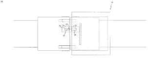
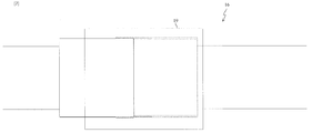
- the optical fiber end faces of the opposing optical connector portions are brought into contact with each other, and then the connection portion is protected by the cover portion 19 (FIG. 7). .
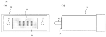
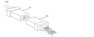
- FIG. 8 is a two-sided view for explaining the optical connector ferrule 28.
- 8A is a front view seen from the opposing optical connector ferrule 29 side
- FIG. 8B is a side view.
- the optical connector ferrule 28 is built in the optical connector housing 24 of the convex optical connector section 17.
- an elastic sheet 36 having the same refractive index as that of the optical fiber is attached to the end face. The sheet 36 softens the impact at the time of fitting the convex optical connector portion 17 and the concave optical connector portion 18, and eliminates the gap between the optical fibers after connection, thereby improving the performance.
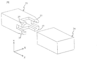
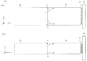
- FIG. 9 is a diagram for explaining the optical connector housings (24, 25).
- the optical connector housings (24, 25) incorporate the MT connector ferrules (28, 29) shown in FIG. 10, respectively.
- the second aligning means is a taper (37, 38) formed in each of the optical connector housings (24, 25), and a housing fine movement mechanism 27 that allows the optical connector housing 24 to move in a direction parallel to the connection surface 17a.
- a force is applied to the optical connector housing 24 by the taper (37, 38), and the housing fine movement mechanism 27 is operated by the force to move the optical connector housing 24. It is characterized by eliminating the deviation from the opposing optical connector housing 25.
- Fig. 11 (a) shows a top view of the optical connector housing (24, 25) before fitting
- Fig. 11 (b) shows a side view thereof.
- the connecting direction of the convex optical connector unit 17 and the concave optical connector unit 18 is the Z-axis direction
- the direction viewed from the top is the Y-axis direction
- the direction viewed from the side is the X-axis direction.
- the optical connector housing 24 is provided with a taper 38, and the optical connector housing 25 is provided with a taper 37. Further, the optical connector housing 24 is fixed to the panel 26 by a housing fine movement mechanism 27 that enables movement in the X-axis direction and the Y-axis direction.
- the housings (24, 25) when the housings (24, 25) are fitted, a force is applied to the optical connector housing 24 by the taper (37, 38).
- the housing fine movement mechanism 27 moves the optical connector housing 24 in the direction of the force by the force, thereby fitting the optical connector housings 24 while correcting the position between the optical connector housings.
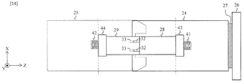
- FIG. 13 and 14 are views for explaining the third aligning means.
- FIG. 13 shows a state before the optical connector ferrules (28, 29) are fitted to each other
- FIG. 14 shows a state after the optical connector ferrules are fitted (28, 29).
- the third alignment means is The second guide pin 32 disposed on the joining surface of the optical connector ferrule (28, 29) in which the end face of the optical fiber appears, the second guide hole 33 into which the second guide pin fits, the optical connector ferrule (28, The fine movement mechanism (43, 44) for moving the ferrule (29) in a direction parallel to the connecting surface (Z-axis direction), and the pressing force so that the optical connector ferrules (28, 29) are closely attached to each other on the joining surface.
- the housing is transparent so that the optical connector ferrules (28, 29) inside the optical connector housing (24, 25) can be observed.
- Optical connector ferrules (28, 29) are built in the optical connector housings (24, 25), respectively.
- the optical connector ferrules (28, 29) have a structure that can be finely moved in the X-axis direction and the Y-axis direction by the ferrule fine movement mechanism (43, 44).
- the position of the optical connector ferrule (28, 29) is adjusted by the ferrule fine movement mechanism (43, 44).
- the optical connector ferrules (28, 29) are movable in the Z-axis direction by the pressing mechanism (41, 42), and are pressed in the connecting surface direction.
- the pressing mechanism (41, 42) is a spring. Therefore, after the third-stage alignment, the optical connector ferrules (28, 29) are pressed in the connecting direction, that is, the optical fiber end faces are pressed against each other.
- the optical cable connection method is as follows.
- Positioning is performed using the first guide pin 22 arranged on the connection surface of the first connector portion 17 and the connection surface of the second connector portion 18 and the first guide hole 23 fitted with this.
- a taper (37, 38) formed in the optical connector housing (24, 25), and a housing that allows the optical connector housing (24, 25) to move in directions (XY directions) parallel to the connection surfaces (17a, 18a).
- the optical connector housings (24, 25) are fitted to each other by using the fine movement mechanism 27, a force is applied to the optical connector housing 24 by the taper (37, 38), and the housing fine movement mechanism 27 is operated by the force.
- the optical connector housing 24 moves to eliminate the displacement between the opposed optical connector housings.
- the second guide pin 32 disposed on the joint surface of the optical connector ferrule (28, 29) where the optical fiber end face is exposed, the second guide hole 33 into which the second guide pin 32 is fitted, and the optical connector ferrule (28, 29) are connected to each other.
- the pressing force is applied so that the ferrule fine movement mechanism (43, 44) that enables movement in the directions (XY directions) parallel to (17a, 18a) and the optical connector ferrules (28, 29) are in close contact with each other at the joint surface.
- the pressing mechanism (41, 42) When the second guide pin 32 and the second guide hole 33 of the optical connector ferrule (28, 29) are fitted together, the optical connector ferrule (28, 29) is displaced due to the displacement of the second guide pin 32 and the second guide hole 33.
- the ferrule fine movement mechanism (43, 44) is actuated by the force to move the optical connector ferrules (28, 29) to eliminate the deviation between the opposing optical connector ferrules, and the pressing mechanism (41, 42). ) Applies the pressing force to the optical connector ferrule (28, 29).
- FIG. 15 is a diagram of the multi-fiber optical connector 16 viewed from the connection surface.
- FIG. 15A shows the connection surface 18a of the concave (second) optical connector portion 18, and
- FIG. 15B shows the connection surface 17a of the convex (first) optical connector portion 17.
- the convex optical connector portion 17 and the concave optical connector portion 18 are capable of super-multifiber optical fiber connection by arranging a plurality of optical connector housings (24, 25).
- the present multi-fiber optical connector includes one or more optical connector housings that respectively house multi-fiber optical connector ferrules, and first guide pins and guide holes that align the optical connector housings.
- Each optical connector housing has a structure in which the optical connector ferrules housed therein are aligned.
- Each optical connector ferrule includes a second guide pin and a guide hole that aligns a plurality of optical fibers that it accommodates.
- this connection method is an optical cable connection method using the above-mentioned multi-fiber optical connector, which comprises a first step of aligning the optical connector housings with a first guide pin and a guide hole, and an optical connector housing with an optical fiber. It comprises a second step of aligning the connector ferrules and a third step of aligning each optical fiber with a second guide pin and a guide hole. (The invention's effect)
- optical connector housing 1 MT connector, 2 MT connector ferrule, 3 guide pins, 4 guide holes, 5 Optical fiber end face, 6 optical fiber tape, 7 Adhesive addition window, 8 optical connector boots, 9 optical closures, 10 Optical closure housing, 11 Optical cable grip, 12 optical fiber housing, 13 optical cable, 14 optical fiber tape, 15 connections, 16 Super multi-fiber optical connector for optical cable, 17 Convex optical connector section 17, 17a connection surface, 18 concave optical connector section 18, 18a connection surface, 19 cover, 20 screw part, 21 screw part, 22 guide pins, 23 guide holes, 24 optical connector housing, 25 optical connector housing, 26 Optical connector mounting panel, 27 housing fine movement mechanism, 28 optical connector ferrule, 29 optical connector ferrule, 30 optical fiber tape, 31 optical fiber tape, 32 guide pins, 33 guide holes, 34 optical fiber end face, 35 optical fiber end face, 36 Elastic body refractive index matching, 37 optical connector housing taper part, 38 Optical connector housing taper part, 41 spring part, 42 spring part, 43 Ferrule fine
Landscapes
- Physics & Mathematics (AREA)
- General Physics & Mathematics (AREA)
- Optics & Photonics (AREA)
- Mechanical Coupling Of Light Guides (AREA)
Abstract
接続時間を短縮でき、且つ接続部の設置スペースを削減できる多心光コネクタ及び光ケーブル接続方法を提供することを目的とする。 本発明に係る多心光コネクタは、3つの位置合わせ手段を持ち、光ケーブル接続時にこれらの位置合わせ手段を順次使用して光ファイバ端面の粗調から微調までを行うこととした。さらに、本多心光コネクタは、光ケーブルに含まれる多数の光ファイバの端面を一斉に接続するため、余剰光ファイバテープが存在せず、従来必要であったクロージャが不要である。
Description
本開示は、光ケーブルを接続するための多心光コネクタ及びその接続方法に関する。
現在、光ケーブルは様々な場所で用いられており、400心、1000心、2000心などの光ケーブルも実用化されている。光ファイバを敷設する場合、その敷設距離が伸びた場合、1本のケーブルで敷設することは大変難しく、ある程度の距離毎に接続点を設けることが必要とされている。現在では、光ケーブルに内蔵する光ファイバは、テープ形状のものが主流で、4心もしくは8心を一括して接続する技術が実用化されている。このとき、接続する方法としては、物理的に光ファイバを溶かして接続してしまう融着接続、もしくは光ファイバ先端にMTコネクタフェルールを取り付けた、MTコネクタ接続が用いられている(図1)。
図1のMTコネクタ1は、光ファイバテープ6をとり詰めたMTコネクタフェルール2を、ガイドピン3をガイド孔4に挿入することによって、高精度に整列させ、光ファイバ5同士を高精度に位置あわせする技術である。光ファイバは、接着剤7によって、MTコネクタフェルールに固定されている。融着接続、およびMTコネクタ接続は、最少単位は4心もしくは8心であるため、接続する作業は手間がかかるという課題が存在した。
また、光ケーブルを接続した際には、接続部を収容するクロージャ(図2)という接続部を保護する筐体が必要になる。図2のクロージャ9は、筐体部10、光ケーブル把持部11、接続余光ファイバテープ収容部12から構成され、接続部15は筐体の中に収容される。このため、接続部は、光ケーブルの直径の何倍も大きくなってしまうという難点が存在した。
これら光ケーブル接続部の大きさを小さくすること、さらには接続時間を短縮することを目的として、様々な技術が提案されている。たとえば、特許文献1では、光接続部の大きさを小さくすることを目的として新しい構造の光クロージャを提案している。一方、特許文献2では、接続作業時間を短縮するために、多心の光ファイバを一括して接続する技術を提案している。
上述のように、多心光ファイバケーブルを敷設する際、必要となる接続作業において、その接続時間が長いという課題、およびその接続部が大きくなり、設置のスペースが必要となるという課題が存在する。そこで、本発明は、上記課題を解決するために、接続時間を短縮でき、且つ接続部の設置スペースを削減できる多心光コネクタ及び光ケーブル接続方法を提供することを目的とする。
上記目的を達成するために、本発明に係る多心光コネクタは3つの位置合わせ手段を持ち、光ケーブル接続時にこれらの位置合わせ手段を順次使用して光ファイバ端面の粗調から微調までを行うこととした。
具体的には、本発明に係る多心光コネクタは、第1コネクタ部と第2コネクタ部を接続することで第1コネクタ部の接続面に現れている複数の光ファイバ端面と第2コネクタ部の接続面に現れている複数の光ファイバ端面とを接続する多心光コネクタであって、
前記接続面において光ファイバ端面をグループ化する光コネクタフェルールと、
それぞれが前記光コネクタフェルールを1つ収容する複数の光コネクタハウジングと、
前記第1コネクタ部の接続面と前記第2コネクタ部の接続面とを位置合わせする第1調心手段と、
前記第1調心手段が前記第1コネクタ部の接続面と前記第2コネクタ部の接続面とを位置合わせした後、対向する前記光コネクタハウジング同士を位置合わせする第2調心手段と、
前記第2調心手段が対向する前記光コネクタハウジング同士を位置合わせした後、対向する前記光コネクタフェルール同士を位置合わせする第3調心手段と、
を備えることを特徴とする。
前記接続面において光ファイバ端面をグループ化する光コネクタフェルールと、
それぞれが前記光コネクタフェルールを1つ収容する複数の光コネクタハウジングと、
前記第1コネクタ部の接続面と前記第2コネクタ部の接続面とを位置合わせする第1調心手段と、
前記第1調心手段が前記第1コネクタ部の接続面と前記第2コネクタ部の接続面とを位置合わせした後、対向する前記光コネクタハウジング同士を位置合わせする第2調心手段と、
前記第2調心手段が対向する前記光コネクタハウジング同士を位置合わせした後、対向する前記光コネクタフェルール同士を位置合わせする第3調心手段と、
を備えることを特徴とする。
また、本発明に係る光ケーブル接続方法は、第1コネクタ部と第2コネクタ部を接続することで第1コネクタ部の接続面に現れている複数の光ファイバ端面と第2コネクタ部の接続面に現れている複数の光ファイバ端面とを接続する多心光コネクタを利用して光ケーブルを接続する光ケーブル接続方法であって、
前記多心光コネクタは、複数の光コネクタハウジングのそれぞれが1つ収容する光コネクタフェルールで前記光ケーブルが有する光ファイバの光ファイバ端面を前記接続面においてグループ化し、
前記第1コネクタ部の接続面と前記第2コネクタ部の接続面とを位置合わせする第1調心手順と、
前記第1調心手順の後、対向する前記光コネクタハウジング同士を位置合わせする第2調心手順と、
前記第2調心手順の後、対向する前記光コネクタフェルール同士を位置合わせする第3調心手順と、
を行うことを特徴とする。
前記多心光コネクタは、複数の光コネクタハウジングのそれぞれが1つ収容する光コネクタフェルールで前記光ケーブルが有する光ファイバの光ファイバ端面を前記接続面においてグループ化し、
前記第1コネクタ部の接続面と前記第2コネクタ部の接続面とを位置合わせする第1調心手順と、
前記第1調心手順の後、対向する前記光コネクタハウジング同士を位置合わせする第2調心手順と、
前記第2調心手順の後、対向する前記光コネクタフェルール同士を位置合わせする第3調心手順と、
を行うことを特徴とする。
本多心光コネクタは、第1コネクタ部と第2コネクタ部を接合する際に、自動的に光ファイバ端面の粗調から微調までがなされる。さらに、本多心光コネクタは、光ケーブルに含まれる多数の光ファイバの端面を一斉に接続するため、余剰光ファイバテープが存在せず、従来必要であったクロージャが不要である。従って、本発明は、接続時間を短縮でき、且つ接続部の設置スペースを削減できる多心光コネクタ及び光ケーブル接続方法を提供することができる。
本発明に係る多心光コネクタのそれぞれの調心手段は次の通りである。
前記第1調心手段は、前記第1コネクタ部の接続面と前記第2コネクタ部の接続面に配置された第1ガイドピンと該第1ガイドピンと嵌合する第1ガイド孔であることを特徴とする。
前記第1調心手段は、前記第1コネクタ部の接続面と前記第2コネクタ部の接続面に配置された第1ガイドピンと該第1ガイドピンと嵌合する第1ガイド孔であることを特徴とする。
前記第2調心手段は、
前記光コネクタハウジングに形成されたテーパー、及び前記光コネクタハウジングを前記接続面に平行な方向へ移動可能とするハウジング微動機構を有し、
対向する前記光コネクタハウジング同士が嵌合するときに、前記テーパーにより前記光コネクタハウジングに力が加わり、該力によって前記ハウジング微動機構が作動して前記光コネクタハウジングが移動して対向する前記光コネクタハウジング間のずれを無くすことを特徴とする。
前記光コネクタハウジングに形成されたテーパー、及び前記光コネクタハウジングを前記接続面に平行な方向へ移動可能とするハウジング微動機構を有し、
対向する前記光コネクタハウジング同士が嵌合するときに、前記テーパーにより前記光コネクタハウジングに力が加わり、該力によって前記ハウジング微動機構が作動して前記光コネクタハウジングが移動して対向する前記光コネクタハウジング間のずれを無くすことを特徴とする。
前記第3調心手段は、
前記光ファイバ端面が現れている前記光コネクタフェルールの接合面に配置された第2ガイドピンと該第2ガイドピンが嵌合する第2ガイド孔、前記光コネクタフェルールを前記接続面に平行な方向へ移動可能とするフェルール微動機構、及び前記光コネクタフェルール同士が前記接合面で密着するように押圧力を印加する押圧機構を有し、
対向する前記光コネクタフェルールの前記第2ガイドピンと前記第2ガイド孔が嵌合するときに、前記第2ガイドピンと前記第2ガイド孔とのずれにより前記光コネクタフェルールに力が加わり、該力によって前記フェルール微動機構が作動して前記光コネクタフェルールが移動して対向する前記光コネクタフェルール間のずれを無くすとともに、前記押圧機構が前記押圧力を前記光コネクタフェルールに印加することを特徴とする。
前記光ファイバ端面が現れている前記光コネクタフェルールの接合面に配置された第2ガイドピンと該第2ガイドピンが嵌合する第2ガイド孔、前記光コネクタフェルールを前記接続面に平行な方向へ移動可能とするフェルール微動機構、及び前記光コネクタフェルール同士が前記接合面で密着するように押圧力を印加する押圧機構を有し、
対向する前記光コネクタフェルールの前記第2ガイドピンと前記第2ガイド孔が嵌合するときに、前記第2ガイドピンと前記第2ガイド孔とのずれにより前記光コネクタフェルールに力が加わり、該力によって前記フェルール微動機構が作動して前記光コネクタフェルールが移動して対向する前記光コネクタフェルール間のずれを無くすとともに、前記押圧機構が前記押圧力を前記光コネクタフェルールに印加することを特徴とする。
また、本発明に係る光ケーブル接続方法のそれぞれの調心手順は次の通りである。
前記第1調心手順では、
前記第1コネクタ部の接続面と前記第2コネクタ部の接続面に配置された第1ガイドピンと該第1ガイドピンと嵌合する第1ガイド孔を利用して位置合わせを行い、
前記第2調心手順では、
前記光コネクタハウジングに形成されたテーパー、及び前記光コネクタハウジングを前記接続面に平行な方向へ移動可能とするハウジング微動機構を利用して、対向する前記光コネクタハウジング同士が嵌合するときに、前記テーパーにより前記光コネクタハウジングに力が加わり、該力によって前記ハウジング微動機構が作動して前記光コネクタハウジングが移動して対向する前記光コネクタハウジング間のずれを無くし、
前記第3調心手順では、
前記光ファイバ端面が現れている前記光コネクタフェルールの接合面に配置された第2ガイドピンと該第2ガイドピンが嵌合する第2ガイド孔、前記光コネクタフェルールを前記接続面に平行な方向へ移動可能とするフェルール微動機構、及び前記光コネクタフェルール同士が前記接合面で密着するように押圧力を印加する押圧機構を利用して、
対向する前記光コネクタフェルールの前記第2ガイドピンと前記第2ガイド孔が嵌合するときに、前記第2ガイドピンと前記第2ガイド孔とのずれにより前記光コネクタフェルールに力が加わり、該力によって前記フェルール微動機構が作動して前記光コネクタフェルールが移動して対向する前記光コネクタフェルール間のずれを無くすとともに、前記押圧機構が前記押圧力を前記光コネクタフェルールに印加すること
を特徴とする。
前記第1調心手順では、
前記第1コネクタ部の接続面と前記第2コネクタ部の接続面に配置された第1ガイドピンと該第1ガイドピンと嵌合する第1ガイド孔を利用して位置合わせを行い、
前記第2調心手順では、
前記光コネクタハウジングに形成されたテーパー、及び前記光コネクタハウジングを前記接続面に平行な方向へ移動可能とするハウジング微動機構を利用して、対向する前記光コネクタハウジング同士が嵌合するときに、前記テーパーにより前記光コネクタハウジングに力が加わり、該力によって前記ハウジング微動機構が作動して前記光コネクタハウジングが移動して対向する前記光コネクタハウジング間のずれを無くし、
前記第3調心手順では、
前記光ファイバ端面が現れている前記光コネクタフェルールの接合面に配置された第2ガイドピンと該第2ガイドピンが嵌合する第2ガイド孔、前記光コネクタフェルールを前記接続面に平行な方向へ移動可能とするフェルール微動機構、及び前記光コネクタフェルール同士が前記接合面で密着するように押圧力を印加する押圧機構を利用して、
対向する前記光コネクタフェルールの前記第2ガイドピンと前記第2ガイド孔が嵌合するときに、前記第2ガイドピンと前記第2ガイド孔とのずれにより前記光コネクタフェルールに力が加わり、該力によって前記フェルール微動機構が作動して前記光コネクタフェルールが移動して対向する前記光コネクタフェルール間のずれを無くすとともに、前記押圧機構が前記押圧力を前記光コネクタフェルールに印加すること
を特徴とする。
本発明に係る多心光コネクタは、前記接続面に配置され、屈折率が前記光ファイバ端面に現れるコアと等しく、弾性をもつ固形整合材をさらに備えることが好ましい。
前記固形整合剤により、接続した際の光ファイバ端面同士の隙間を埋めるとともに、接続時の衝撃を緩和することができる。
前記固形整合剤により、接続した際の光ファイバ端面同士の隙間を埋めるとともに、接続時の衝撃を緩和することができる。
なお、上記各発明は、可能な限り組み合わせることができる。
本発明は、多心光ケーブルに一括して接続する機構を設けることにより、接続時における作業量を大幅に減少させるとともに、接続部に必要であったクロージャを無くし、接続部のスペースを大幅に減少させることができる。
つまり、本発明は、接続時間を短縮でき、且つ接続部の設置スペースを削減できる多心光コネクタ及び光ケーブル接続方法を提供することができる。
つまり、本発明は、接続時間を短縮でき、且つ接続部の設置スペースを削減できる多心光コネクタ及び光ケーブル接続方法を提供することができる。
添付の図面を参照して本発明の実施形態を説明する。以下に説明する実施形態は本発明の実施例であり、本発明は、以下の実施形態に制限されるものではない。なお、本明細書及び図面において符号が同じ構成要素は、相互に同一のものを示すものとする。
図3は、本実施形態の光ケーブル用光コネクタ16を説明する図である。光ケーブル用光コネクタ16は、第1コネクタ部17と第2コネクタ部18を接続することで第1コネクタ部17の接続面17aに現れている複数の光ファイバ端面と第2コネクタ部18の接続面18aに現れている複数の光ファイバ端面とを接続する多心光コネクタであって、
接続面(17a、18a)において光ファイバ端面をグループ化する光コネクタフェルール(28、29)と、
それぞれが前記光コネクタフェルールを1つ収容する複数の光コネクタハウジング(24、25)と、
第1コネクタ部17の接続面17aと第2コネクタ部18の接続面18aとを位置合わせする第1調心手段と、
前記第1調心手段が第1コネクタ部17の接続面17aと第2コネクタ部18の接続面18aとを位置合わせした後、対向する光コネクタハウジング同士(24、25)を位置合わせする第2調心手段と、
前記第2調心手段が対向する光コネクタハウジング同士(24、25)を位置合わせした後、対向する光コネクタフェルール同士(28,29)を位置合わせする第3調心手段と、
を備える。
接続面(17a、18a)において光ファイバ端面をグループ化する光コネクタフェルール(28、29)と、
それぞれが前記光コネクタフェルールを1つ収容する複数の光コネクタハウジング(24、25)と、
第1コネクタ部17の接続面17aと第2コネクタ部18の接続面18aとを位置合わせする第1調心手段と、
前記第1調心手段が第1コネクタ部17の接続面17aと第2コネクタ部18の接続面18aとを位置合わせした後、対向する光コネクタハウジング同士(24、25)を位置合わせする第2調心手段と、
前記第2調心手段が対向する光コネクタハウジング同士(24、25)を位置合わせした後、対向する光コネクタフェルール同士(28,29)を位置合わせする第3調心手段と、
を備える。
光ケーブル用の多心光コネクタ16は、光ケーブル50に取り付けられた凹型(第2)光コネクタ部18、凸型(第1)光コネクタ部17、および覆部19より構成される。凹型光コネクタ部18と凸型光コネクタ部17の接続が終了したあと、凹型光コネクタに形成されたネジ部20と、覆部19に形成されたネジ部21をかみ合わせることにより、凹型光コネクタ部18と凸型光コネクタ部17を軸方向に押し付けるとともに、凹型光コネクタ部18と凸型光コネクタ部17の接続部を覆い、防水機能を持たせることを実現している。
凸型光コネクタ部17の接続面17aと凹型光コネクタ部18の接続面18aには、それぞれガイドピン22とガイド孔23が設けられており、接続する際、最初にガイドピン22をガイド孔23に挿入することにより、接続の位置あわせと大まかな調心を実現する。
凸型光コネクタ部17と凹型光コネクタ部18内部には、それぞれ光コネクタハウジング(24、25)が内蔵されている。光コネクタハウジング24は、コネクタ内のパネル26に取り付けられており、光コネクタハウジング24は、接続面(17a、18a)に平行な方向へ移動可能な構造となっている。
光コネクタハウジング(24、25)は、それぞれ光ケーブル内部に収容されている光ファイバテープ(30、31)を固定した光コネクタフェルール(28、29)を内蔵する。光コネクタフェルール(28、29)は、それぞれが備えるガイドピン32とガイド孔33によって位置あわせされ、最終的に光コネクタフェルール(28、29)のそれぞれの端面に保持されている光ファイバ端面同士(34、35)を高精度に接続する。
図4~図7は、多心光コネクタ16の接続シーケンスを説明する図である。多心光コネクタ16を利用した光ケーブルの接続は以下の3段階で行われる。
第一段階は、第1コネクタ部17の接続面17aと第2コネクタ部18の接続面18aとを位置合わせする第1調心手順である(図4)。第1調心手順では、ガイドピン22が、ガイドピン孔23に挿入され、接続における第一段階の調心が行われる。この第一段階の調心により、光コネクタハウジング(24、25)の嵌合が可能となる。光コネクタハウジング(24、25)は、例えば、MTコネクタフェルールである。
第二段階は、対向する光コネクタハウジング同士(24、25)を位置合わせする第2調心手順である(図5)。第2調心手順では、光コネクタハウジング同士(24、25)の嵌合が行われ、第二段階の調心が行われる。この第二段階の調心により、光コネクタフェルール(28、29)のガイドピン32とガイド孔33の嵌合が可能となる。
第三段階は、対向する光コネクタフェルール同士(28、29)を位置合わせする第3調心手順である(図6)。第3調心手順では、ガイドピン32がガイド孔33に挿入され、第三段階の調心が行われる。この第三段階の調心により、最終的な光ファイバ同士の調心が行われ、光ファイバの高精度な調心が実現される。
第3調心手順で、対向する光コネクタ部(凸型光コネクタ部17と凹型光コネクタ部18)の光ファイバ端面が付き合わされた後、覆部19によって接続部が保護される(図7)。
第一段階は、第1コネクタ部17の接続面17aと第2コネクタ部18の接続面18aとを位置合わせする第1調心手順である(図4)。第1調心手順では、ガイドピン22が、ガイドピン孔23に挿入され、接続における第一段階の調心が行われる。この第一段階の調心により、光コネクタハウジング(24、25)の嵌合が可能となる。光コネクタハウジング(24、25)は、例えば、MTコネクタフェルールである。
第二段階は、対向する光コネクタハウジング同士(24、25)を位置合わせする第2調心手順である(図5)。第2調心手順では、光コネクタハウジング同士(24、25)の嵌合が行われ、第二段階の調心が行われる。この第二段階の調心により、光コネクタフェルール(28、29)のガイドピン32とガイド孔33の嵌合が可能となる。
第三段階は、対向する光コネクタフェルール同士(28、29)を位置合わせする第3調心手順である(図6)。第3調心手順では、ガイドピン32がガイド孔33に挿入され、第三段階の調心が行われる。この第三段階の調心により、最終的な光ファイバ同士の調心が行われ、光ファイバの高精度な調心が実現される。
第3調心手順で、対向する光コネクタ部(凸型光コネクタ部17と凹型光コネクタ部18)の光ファイバ端面が付き合わされた後、覆部19によって接続部が保護される(図7)。
図8は、光コネクタフェルール28を説明する2面図である。図8(a)は対向する光コネクタフェルール29側から見た正面図、図8(b)は側面図である。光コネクタフェルール28は、凸型光コネクタ部17の光コネクタハウジング24に内蔵されている。図8のように端面に、光ファイバと屈折率を等しくする弾性体のシート36が貼り付けられている。シート36は、凸型光コネクタ部17と凹型光コネクタ部18とを嵌合する際の衝撃を和らげるとともに、接続後の光ファイバ間の間隙をなくし、性能の向上を図ることができる。
図9は、光コネクタハウジング(24、25)を説明する図である。光コネクタハウジング(24、25)は、それぞれ図10に示すMTコネクタフェルール(28、29)を内蔵する。
図11及び図12は、第2調心手段を説明する図である。前記第2調心手段は、光コネクタハウジング(24、25)にそれぞれ形成されたテーパー(37、38)、及び光コネクタハウジング24を接続面17aに平行な方向へ移動可能とするハウジング微動機構27を有し、
光コネクタハウジング同士(24、25)が嵌合するときに、テーパー(37、38)により光コネクタハウジング24に力が加わり、該力によって前記ハウジング微動機構27が作動して光コネクタハウジング24が移動して対向する光コネクタハウジング25とのずれを無くすことを特徴とする。
光コネクタハウジング同士(24、25)が嵌合するときに、テーパー(37、38)により光コネクタハウジング24に力が加わり、該力によって前記ハウジング微動機構27が作動して光コネクタハウジング24が移動して対向する光コネクタハウジング25とのずれを無くすことを特徴とする。
光コネクタハウジング(24、25)の嵌合前の状態を上面から見た図を図11(a)に、側面から観察した図を図11(b)に示す。ここで、凸型光コネクタ部17と凹型光コネクタ部18の接続方向をZ軸方向とし、上面から見る方向をY軸方向、側面から見る方向をX軸方向とする。
光コネクタハウジング24にはテーパー38、光コネクタハウジング25にはテーパー37が設けられている。さらに、光コネクタハウジング24は、パネル26との間でX軸方向及びY軸方向に移動可能とさせるハウジング微動機構27で固定されている。
図12に示すように、ハウジング(24、25)が嵌合する際、テーパー(37、38)により光コネクタハウジング24に力が加わる。当該力によりハウジング微動機構27が光コネクタハウジング24を当該力の方向へ移動させることで光コネクタハウジング間の位置を修正しながら嵌合する。
図13及び図14は、第3調心手段を説明する図である。図13は光コネクタフェルール同士(28,29)が嵌合する前の状態を示し、図14は光コネクタフェルール同士が嵌合(28,29)した後の状態を示す。第3調心手段は、
前記光ファイバ端面が現れている光コネクタフェルール(28、29)の接合面に配置された第2ガイドピン32と該第2ガイドピンが嵌合する第2ガイド孔33、光コネクタフェルール(28、29)を前記接続面に平行な方向(Z軸方向)へ移動可能とするフェルール微動機構(43、44)、及び光コネクタフェルール同士(28,29)が前記接合面で密着するように押圧力を印加する押圧機構(41、42)を有し、
対向する光コネクタフェルール(28,29)の第2ガイドピン32と第2ガイド孔33が嵌合するときに、第2ガイドピン32と第2ガイド孔33とのずれにより光コネクタフェルール(28,29)に力が加わり、該力によってフェルール微動機構(43、44)が作動して光コネクタフェルール(28,29)が移動して対向する前記光コネクタフェルール間のずれを無くすとともに、押圧機構(41、42)が前記押圧力を光コネクタフェルール(28,29)に印加すること
を特徴とする。
前記光ファイバ端面が現れている光コネクタフェルール(28、29)の接合面に配置された第2ガイドピン32と該第2ガイドピンが嵌合する第2ガイド孔33、光コネクタフェルール(28、29)を前記接続面に平行な方向(Z軸方向)へ移動可能とするフェルール微動機構(43、44)、及び光コネクタフェルール同士(28,29)が前記接合面で密着するように押圧力を印加する押圧機構(41、42)を有し、
対向する光コネクタフェルール(28,29)の第2ガイドピン32と第2ガイド孔33が嵌合するときに、第2ガイドピン32と第2ガイド孔33とのずれにより光コネクタフェルール(28,29)に力が加わり、該力によってフェルール微動機構(43、44)が作動して光コネクタフェルール(28,29)が移動して対向する前記光コネクタフェルール間のずれを無くすとともに、押圧機構(41、42)が前記押圧力を光コネクタフェルール(28,29)に印加すること
を特徴とする。
図13及び図14では、光コネクタハウジング(24、25)の内部の光コネクタフェルール(28,29)が観察できるようにハウジングを透明化して記載している。光コネクタハウジング(24、25)には光コネクタフェルール(28、29)が、それぞれ内蔵されている。光コネクタフェルール(28、29)は、フェルール微動機構(43、44)によりX軸方向及びY軸方向に微動可能な構造となっている。
光コネクタハウジング(24、25)が嵌合した後、ガイドピン32とガイドピン孔33が嵌合し、第三段階の調心が実現される。この際、フェルール微動機構(43、44)によって、光コネクタフェルール(28、29)の位置が調整される。また、光コネクタフェルール(28、29)は、押圧機構(41、42)によりZ軸方向に移動可能であるとともに、接続面方向に押圧が加えられる。例えば、押圧機構(41、42)はばねである。このため、第三段階の調心が行われた後には、接続方向に光コネクタフェルール(28、29)に押圧がかかる、つまり、光ファイバ端面同士を押し付ける構造となっている。
以上をまとめると光ケーブル接続方法は次のような方法である。
前記第1調心手順では、
第1コネクタ部17の接続面と第2コネクタ部18の接続面に配置された第1ガイドピン22とこれと嵌合する第1ガイド孔23を利用して位置合わせを行う。
前記第2調心手順では、
光コネクタハウジング(24、25)に形成されたテーパー(37、38)、及び光コネクタハウジング(24、25)を接続面(17a,18a)に平行な方向(XY方向)へ移動可能とするハウジング微動機構27を利用して、光コネクタハウジング同士(24、25)が嵌合するときに、テーパー(37、38)により光コネクタハウジング24に力が加わり、該力によってハウジング微動機構27が作動して光コネクタハウジング24が移動して対向する光コネクタハウジング間のずれを無くす。
前記第3調心手順では、
前記光ファイバ端面が現れている光コネクタフェルール(28、29)の接合面に配置された第2ガイドピン32とこれが嵌合する第2ガイド孔33、光コネクタフェルール(28、29)を接続面(17a,18a)に平行な方向(XY方向)へ移動可能とするフェルール微動機構(43,44)、及び光コネクタフェルール同士(28、29)が前記接合面で密着するように押圧力を印加する押圧機構(41,42)を利用して、
光コネクタフェルール(28、29)の第2ガイドピン32と第2ガイド孔33が嵌合するときに、第2ガイドピン32と第2ガイド孔33とのずれにより光コネクタフェルール(28、29)に力が加わり、該力によってフェルール微動機構(43,44)が作動して光コネクタフェルール(28、29)が移動して対向する光コネクタフェルール間のずれを無くすとともに、押圧機構(41,42)が前記押圧力を光コネクタフェルール(28、29)に印加する。
前記第1調心手順では、
第1コネクタ部17の接続面と第2コネクタ部18の接続面に配置された第1ガイドピン22とこれと嵌合する第1ガイド孔23を利用して位置合わせを行う。
前記第2調心手順では、
光コネクタハウジング(24、25)に形成されたテーパー(37、38)、及び光コネクタハウジング(24、25)を接続面(17a,18a)に平行な方向(XY方向)へ移動可能とするハウジング微動機構27を利用して、光コネクタハウジング同士(24、25)が嵌合するときに、テーパー(37、38)により光コネクタハウジング24に力が加わり、該力によってハウジング微動機構27が作動して光コネクタハウジング24が移動して対向する光コネクタハウジング間のずれを無くす。
前記第3調心手順では、
前記光ファイバ端面が現れている光コネクタフェルール(28、29)の接合面に配置された第2ガイドピン32とこれが嵌合する第2ガイド孔33、光コネクタフェルール(28、29)を接続面(17a,18a)に平行な方向(XY方向)へ移動可能とするフェルール微動機構(43,44)、及び光コネクタフェルール同士(28、29)が前記接合面で密着するように押圧力を印加する押圧機構(41,42)を利用して、
光コネクタフェルール(28、29)の第2ガイドピン32と第2ガイド孔33が嵌合するときに、第2ガイドピン32と第2ガイド孔33とのずれにより光コネクタフェルール(28、29)に力が加わり、該力によってフェルール微動機構(43,44)が作動して光コネクタフェルール(28、29)が移動して対向する光コネクタフェルール間のずれを無くすとともに、押圧機構(41,42)が前記押圧力を光コネクタフェルール(28、29)に印加する。
図15は、多心光コネクタ16を接続面から見た図である。図15(a)は、凹型(第2)光コネクタ部18の接続面18aであり、図15(b)は、凸型(第1)光コネクタ部17の接続面17aである。凸型光コネクタ部17及び凹型光コネクタ部18は、それぞれ光コネクタハウジング(24、25)を複数並べることにより、超多心の光ファイバ接続を可能としている。
[付記]
以下は、本実施形態の多心光コネクタ及び接続方法を説明したものである。
(目的)
本発明は、短時間で多心の光ファイバを接続可能とすること、及び接続部のスペースを大幅に削減することを目的とする。
(手段)
本多心光コネクタは、それぞれ多心の光コネクタフェルールを収容する1以上の光コネクタハウジングと、各光コネクタハウジングを整列させる第1のガイドピンおよびガイド孔とを備える。各光コネクタハウジングは、自身が収容する各光コネクタフェルールを整列させる構造である。各光コネクタフェルールは、自身が収容する複数の光ファイバを調心させる第2のガイドピンおよびガイド孔を備える。
また、本接続方法は、上記多心光コネクタを用いた光ケーブルの接続方法であって、第1のガイドピンおよびガイド孔により各光コネクタハウジングを整列させる第1のステップと、光コネクタハウジングにより光コネクタフェルールを整列させる第2のステップと、第2のガイドピンおよびガイド孔により各光ファイバを調心させる第3のステップとを備える。
(発明の効果)
当該光ケーブル用光コネクタを用いると、短時間での多心光ファイバ接続が実現可能であるとともに、従来必要とされる光クロージャが不必要となり、接続部のスペースを大幅に減少させることができる。
以下は、本実施形態の多心光コネクタ及び接続方法を説明したものである。
(目的)
本発明は、短時間で多心の光ファイバを接続可能とすること、及び接続部のスペースを大幅に削減することを目的とする。
(手段)
本多心光コネクタは、それぞれ多心の光コネクタフェルールを収容する1以上の光コネクタハウジングと、各光コネクタハウジングを整列させる第1のガイドピンおよびガイド孔とを備える。各光コネクタハウジングは、自身が収容する各光コネクタフェルールを整列させる構造である。各光コネクタフェルールは、自身が収容する複数の光ファイバを調心させる第2のガイドピンおよびガイド孔を備える。
また、本接続方法は、上記多心光コネクタを用いた光ケーブルの接続方法であって、第1のガイドピンおよびガイド孔により各光コネクタハウジングを整列させる第1のステップと、光コネクタハウジングにより光コネクタフェルールを整列させる第2のステップと、第2のガイドピンおよびガイド孔により各光ファイバを調心させる第3のステップとを備える。
(発明の効果)
当該光ケーブル用光コネクタを用いると、短時間での多心光ファイバ接続が実現可能であるとともに、従来必要とされる光クロージャが不必要となり、接続部のスペースを大幅に減少させることができる。
1 MTコネクタ、
2 MTコネクタフェルール、
3 ガイドピン、
4 ガイド孔、
5 光ファイバ端面、
6 光ファイバテープ、
7 接着剤添加窓、
8 光コネクタブーツ、
9 光クロージャ、
10 光クロージャ筐体、
11 光ケーブル把持部、
12 光ファイバ収容部、
13 光ケーブル、
14 光ファイバテープ、
15 接続部、
16 光ケーブル用超多心光コネクタ、
17 凸型光コネクタ部17、
17a 接続面、
18 凹型光コネクタ部18、
18a 接続面、
19 覆部、
20 ネジ部、
21 ネジ部、
22 ガイドピン、
23 ガイド孔、
24 光コネクタハウジング、
25 光コネクタハウジング、
26 光コネクタ取り付け用パネル、
27 ハウジング微動機構、
28 光コネクタフェルール、
29 光コネクタフェルール、
30 光ファイバテープ、
31 光ファイバテープ、
32 ガイドピン、
33 ガイド孔、
34 光ファイバ端面、
35 光ファイバ端面、
36 弾性体屈折率整合、
37 光コネクタハウジングテーパ部、
38 光コネクタハウジングテーパ部、
41 ばね部、
42 ばね部、
43 フェルール微動機構、
44 フェルール微動機構、
50 光ケーブル
2 MTコネクタフェルール、
3 ガイドピン、
4 ガイド孔、
5 光ファイバ端面、
6 光ファイバテープ、
7 接着剤添加窓、
8 光コネクタブーツ、
9 光クロージャ、
10 光クロージャ筐体、
11 光ケーブル把持部、
12 光ファイバ収容部、
13 光ケーブル、
14 光ファイバテープ、
15 接続部、
16 光ケーブル用超多心光コネクタ、
17 凸型光コネクタ部17、
17a 接続面、
18 凹型光コネクタ部18、
18a 接続面、
19 覆部、
20 ネジ部、
21 ネジ部、
22 ガイドピン、
23 ガイド孔、
24 光コネクタハウジング、
25 光コネクタハウジング、
26 光コネクタ取り付け用パネル、
27 ハウジング微動機構、
28 光コネクタフェルール、
29 光コネクタフェルール、
30 光ファイバテープ、
31 光ファイバテープ、
32 ガイドピン、
33 ガイド孔、
34 光ファイバ端面、
35 光ファイバ端面、
36 弾性体屈折率整合、
37 光コネクタハウジングテーパ部、
38 光コネクタハウジングテーパ部、
41 ばね部、
42 ばね部、
43 フェルール微動機構、
44 フェルール微動機構、
50 光ケーブル
Claims (7)
- 第1コネクタ部と第2コネクタ部を接続することで第1コネクタ部の接続面に現れている複数の光ファイバ端面と第2コネクタ部の接続面に現れている複数の光ファイバ端面とを接続する多心光コネクタであって、
前記接続面において光ファイバ端面をグループ化する光コネクタフェルールと、
それぞれが前記光コネクタフェルールを1つ収容する複数の光コネクタハウジングと、
前記第1コネクタ部の接続面と前記第2コネクタ部の接続面とを位置合わせする第1調心手段と、
前記第1調心手段が前記第1コネクタ部の接続面と前記第2コネクタ部の接続面とを位置合わせした後、対向する前記光コネクタハウジング同士を位置合わせする第2調心手段と、
前記第2調心手段が対向する前記光コネクタハウジング同士を位置合わせした後、対向する前記光コネクタフェルール同士を位置合わせする第3調心手段と、
を備えることを特徴とする多心光コネクタ。 - 前記第1調心手段は、前記第1コネクタ部の接続面と前記第2コネクタ部の接続面に配置された第1ガイドピンと該第1ガイドピンと嵌合する第1ガイド孔であることを特徴とする請求項1に記載の多心光コネクタ。
- 前記第2調心手段は、
前記光コネクタハウジングに形成されたテーパー、及び前記光コネクタハウジングを前記接続面に平行な方向へ移動可能とするハウジング微動機構を有し、
対向する前記光コネクタハウジング同士が嵌合するときに、前記テーパーにより前記光コネクタハウジングに力が加わり、該力によって前記ハウジング微動機構が作動して前記光コネクタハウジングが移動して対向する前記光コネクタハウジング間のずれを無くすこと
を特徴とする請求項1又は2に記載の多心光コネクタ。 - 前記第3調心手段は、
前記光ファイバ端面が現れている前記光コネクタフェルールの接合面に配置された第2ガイドピンと該第2ガイドピンが嵌合する第2ガイド孔、前記光コネクタフェルールを前記接続面に平行な方向へ移動可能とするフェルール微動機構、及び前記光コネクタフェルール同士が前記接合面で密着するように押圧力を印加する押圧機構を有し、
対向する前記光コネクタフェルールの前記第2ガイドピンと前記第2ガイド孔が嵌合するときに、前記第2ガイドピンと前記第2ガイド孔とのずれにより前記光コネクタフェルールに力が加わり、該力によって前記フェルール微動機構が作動して前記光コネクタフェルールが移動して対向する前記光コネクタフェルール間のずれを無くすとともに、前記押圧機構が前記押圧力を前記光コネクタフェルールに印加すること
を特徴とする請求項1から3のいずれかに記載の多心光コネクタ。 - 前記接続面に配置され、屈折率が前記光ファイバ端面に現れるコアと等しく、弾性をもつ固形整合材をさらに備えることを特徴とする請求項1から4のいずれかに記載の多心光コネクタ。
- 第1コネクタ部と第2コネクタ部を接続することで第1コネクタ部の接続面に現れている複数の光ファイバ端面と第2コネクタ部の接続面に現れている複数の光ファイバ端面とを接続する多心光コネクタを利用して光ケーブルを接続する光ケーブル接続方法であって、
前記多心光コネクタは、複数の光コネクタハウジングのそれぞれが1つ収容する光コネクタフェルールで前記光ケーブルが有する光ファイバの光ファイバ端面を前記接続面においてグループ化し、
前記第1コネクタ部の接続面と前記第2コネクタ部の接続面とを位置合わせする第1調心手順と、
前記第1調心手順の後、対向する前記光コネクタハウジング同士を位置合わせする第2調心手順と、
前記第2調心手順の後、対向する前記光コネクタフェルール同士を位置合わせする第3調心手順と、
を行うことを特徴とする光ケーブル接続方法。 - 前記第1調心手順では、
前記第1コネクタ部の接続面と前記第2コネクタ部の接続面に配置された第1ガイドピンと該第1ガイドピンと嵌合する第1ガイド孔を利用して位置合わせを行い、
前記第2調心手順では、
前記光コネクタハウジングに形成されたテーパー、及び前記光コネクタハウジングを前記接続面に平行な方向へ移動可能とするハウジング微動機構を利用して、対向する前記光コネクタハウジング同士が嵌合するときに、前記テーパーにより前記光コネクタハウジングに力が加わり、該力によって前記ハウジング微動機構が作動して前記光コネクタハウジングが移動して対向する前記光コネクタハウジング間のずれを無くし、
前記第3調心手順では、
前記光ファイバ端面が現れている前記光コネクタフェルールの接合面に配置された第2ガイドピンと該第2ガイドピンが嵌合する第2ガイド孔、前記光コネクタフェルールを前記接続面に平行な方向へ移動可能とするフェルール微動機構、及び前記光コネクタフェルール同士が前記接合面で密着するように押圧力を印加する押圧機構を利用して、
対向する前記光コネクタフェルールの前記第2ガイドピンと前記第2ガイド孔が嵌合するときに、前記第2ガイドピンと前記第2ガイド孔とのずれにより前記光コネクタフェルールに力が加わり、該力によって前記フェルール微動機構が作動して前記光コネクタフェルールが移動して対向する前記光コネクタフェルール間のずれを無くすとともに、前記押圧機構が前記押圧力を前記光コネクタフェルールに印加すること
を特徴とする請求項6に記載の光ケーブル接続方法。
Priority Applications (1)
| Application Number | Priority Date | Filing Date | Title |
|---|---|---|---|
| US17/285,810 US11740414B2 (en) | 2018-10-24 | 2019-10-09 | Multifiber optical connector and optical cable connection method |
Applications Claiming Priority (2)
| Application Number | Priority Date | Filing Date | Title |
|---|---|---|---|
| JP2018-200363 | 2018-10-24 | ||
| JP2018200363A JP7028137B2 (ja) | 2018-10-24 | 2018-10-24 | 多心光コネクタ及び光ケーブル接続方法 |
Publications (1)
| Publication Number | Publication Date |
|---|---|
| WO2020085093A1 true WO2020085093A1 (ja) | 2020-04-30 |
Family
ID=70331944
Family Applications (1)
| Application Number | Title | Priority Date | Filing Date |
|---|---|---|---|
| PCT/JP2019/039847 Ceased WO2020085093A1 (ja) | 2018-10-24 | 2019-10-09 | 多心光コネクタ及び光ケーブル接続方法 |
Country Status (3)
| Country | Link |
|---|---|
| US (1) | US11740414B2 (ja) |
| JP (1) | JP7028137B2 (ja) |
| WO (1) | WO2020085093A1 (ja) |
Families Citing this family (2)
| Publication number | Priority date | Publication date | Assignee | Title |
|---|---|---|---|---|
| JP2022048642A (ja) * | 2020-09-15 | 2022-03-28 | 国立研究開発法人産業技術総合研究所 | 光学装置及び光学システム |
| US12153265B2 (en) * | 2022-03-30 | 2024-11-26 | Enplas Corporation | Ferrule, optical connector, and optical connector module |
Citations (9)
| Publication number | Priority date | Publication date | Assignee | Title |
|---|---|---|---|---|
| JPH1050400A (ja) * | 1996-05-17 | 1998-02-20 | Framatome Connectors Internatl | バックパネルコネクタシステム |
| JP2002098860A (ja) * | 2000-07-12 | 2002-04-05 | Molex Inc | 光コネクタ用の整列装置 |
| WO2012029442A1 (ja) * | 2010-09-01 | 2012-03-08 | オリンパス株式会社 | 光コネクタ |
| JP2014112164A (ja) * | 2012-12-05 | 2014-06-19 | Hitachi Metals Ltd | 光ファイバ接続構造 |
| JP2016139092A (ja) * | 2015-01-29 | 2016-08-04 | Seiオプティフロンティア株式会社 | 拡張部材及びピン挿入具 |
| US20170010421A1 (en) * | 2015-07-06 | 2017-01-12 | Xyratex Technology Limited | Optical connectors |
| EP3168662A1 (en) * | 2015-11-16 | 2017-05-17 | Siemens Aktiengesellschaft | Alignment assembly and subsea fiber optical connector |
| US20170199338A1 (en) * | 2014-10-31 | 2017-07-13 | Hewlett Packard Enterprise Development Lp | Blind-mating optical ferrule assemblies |
| JP2017134310A (ja) * | 2016-01-29 | 2017-08-03 | 株式会社フジクラ | 光コネクタ及び光コネクタシステム |
Family Cites Families (5)
| Publication number | Priority date | Publication date | Assignee | Title |
|---|---|---|---|---|
| JP5344624B2 (ja) | 2010-01-20 | 2013-11-20 | 日本電信電話株式会社 | 光接続器およびこれを用いた光ケーブルの接続方法 |
| KR101563797B1 (ko) * | 2011-06-17 | 2015-10-27 | 스미토모 덴키 고교 가부시키가이샤 | 광 접속 부재, 광 접속 구조, 및 광 접속 부재의 제조 방법 |
| RU2642534C2 (ru) * | 2012-04-11 | 2018-01-25 | Нанопресижен Продактс, Инк. | Муфта для оптоволоконного коннектора, имеющая криволинейную внешнюю поверхность для выравнивания |
| JP6265482B2 (ja) | 2014-03-06 | 2018-01-24 | 日本電信電話株式会社 | 光ケーブル接続用クロージャ |
| US9274287B2 (en) * | 2014-05-13 | 2016-03-01 | Senko Advanced Components, Inc. | Optical fiber connector and ferrule |
-
2018
- 2018-10-24 JP JP2018200363A patent/JP7028137B2/ja active Active
-
2019
- 2019-10-09 WO PCT/JP2019/039847 patent/WO2020085093A1/ja not_active Ceased
- 2019-10-09 US US17/285,810 patent/US11740414B2/en active Active
Patent Citations (9)
| Publication number | Priority date | Publication date | Assignee | Title |
|---|---|---|---|---|
| JPH1050400A (ja) * | 1996-05-17 | 1998-02-20 | Framatome Connectors Internatl | バックパネルコネクタシステム |
| JP2002098860A (ja) * | 2000-07-12 | 2002-04-05 | Molex Inc | 光コネクタ用の整列装置 |
| WO2012029442A1 (ja) * | 2010-09-01 | 2012-03-08 | オリンパス株式会社 | 光コネクタ |
| JP2014112164A (ja) * | 2012-12-05 | 2014-06-19 | Hitachi Metals Ltd | 光ファイバ接続構造 |
| US20170199338A1 (en) * | 2014-10-31 | 2017-07-13 | Hewlett Packard Enterprise Development Lp | Blind-mating optical ferrule assemblies |
| JP2016139092A (ja) * | 2015-01-29 | 2016-08-04 | Seiオプティフロンティア株式会社 | 拡張部材及びピン挿入具 |
| US20170010421A1 (en) * | 2015-07-06 | 2017-01-12 | Xyratex Technology Limited | Optical connectors |
| EP3168662A1 (en) * | 2015-11-16 | 2017-05-17 | Siemens Aktiengesellschaft | Alignment assembly and subsea fiber optical connector |
| JP2017134310A (ja) * | 2016-01-29 | 2017-08-03 | 株式会社フジクラ | 光コネクタ及び光コネクタシステム |
Also Published As
| Publication number | Publication date |
|---|---|
| US11740414B2 (en) | 2023-08-29 |
| JP7028137B2 (ja) | 2022-03-02 |
| US20210341687A1 (en) | 2021-11-04 |
| JP2020067567A (ja) | 2020-04-30 |
Similar Documents
| Publication | Publication Date | Title |
|---|---|---|
| JP5759183B2 (ja) | 光コネクタ及びその組立方法 | |
| CN110178063B (zh) | 光纤保持部件、光连接器及光耦合构造 | |
| US20100054670A1 (en) | Field installable fiber optic connector and installation tool | |
| KR20020039320A (ko) | 광섬유 커넥터 | |
| CN109901268A (zh) | 一种可现场拼接的光纤连接器 | |
| JP2019066771A (ja) | 光コネクタおよび光接続構造 | |
| JP2021026103A (ja) | 光コネクタ | |
| WO2020085093A1 (ja) | 多心光コネクタ及び光ケーブル接続方法 | |
| US8075198B2 (en) | Reversible fiber connector with mechanical sliding splice | |
| US20230236367A1 (en) | Optical fiber connection component and method for manufacturing optical fiber connection component | |
| US7887244B2 (en) | Reversible fiber connector with mechanical splice and sliding lock | |
| JPWO2004074892A1 (ja) | 光伝送媒体の接続方法、光学接続構造及び光伝送媒体接続部品 | |
| WO2021157150A1 (ja) | 光ファイバピッチ変換治具、光コネクタ、ピッチ変換コード、光変換箱、および光ファイバのピッチ変換方法 | |
| WO2022244039A1 (ja) | 光コネクタ及びその製造方法 | |
| JPH11160575A (ja) | 光コネクタ及びこれを用いた光コネクタの形成方法 | |
| JP3989316B2 (ja) | 光ファイバの接続方法および光ファイバの接続構造 | |
| WO2024142472A1 (ja) | 光ファイバ保持部品およびフェルールアセンブリ | |
| US10989882B2 (en) | Optical connector | |
| JP3710532B2 (ja) | 光コネクタの組立方法 | |
| WO2024166261A1 (ja) | 光コネクタ及びその製造方法 | |
| CN212207749U (zh) | 一种双芯插芯连接器及其适配器组件 | |
| GB2576688A (en) | Connector Loader | |
| JP2013134457A (ja) | 多心光コネクタ、及び多心光コネクタの組付方法 | |
| JP2004252159A (ja) | 現場組立光コネクタ及びその組立方法 | |
| JP2004045936A (ja) | 光ファイバ接続用部品、光ファイバ接続構造および光ファイバ接続方法 |
Legal Events
| Date | Code | Title | Description |
|---|---|---|---|
| 121 | Ep: the epo has been informed by wipo that ep was designated in this application |
Ref document number: 19875327 Country of ref document: EP Kind code of ref document: A1 |
|
| NENP | Non-entry into the national phase |
Ref country code: DE |
|
| 122 | Ep: pct application non-entry in european phase |
Ref document number: 19875327 Country of ref document: EP Kind code of ref document: A1 |