US8075198B2 - Reversible fiber connector with mechanical sliding splice - Google Patents
Reversible fiber connector with mechanical sliding splice Download PDFInfo
- Publication number
- US8075198B2 US8075198B2 US12/489,793 US48979309A US8075198B2 US 8075198 B2 US8075198 B2 US 8075198B2 US 48979309 A US48979309 A US 48979309A US 8075198 B2 US8075198 B2 US 8075198B2
- Authority
- US
- United States
- Prior art keywords
- optical fiber
- anvil
- groove
- stub
- splice
- Prior art date
- Legal status (The legal status is an assumption and is not a legal conclusion. Google has not performed a legal analysis and makes no representation as to the accuracy of the status listed.)
- Active, expires
Links
- 239000000835 fiber Substances 0.000 title claims abstract description 84
- 230000002441 reversible effect Effects 0.000 title description 15
- 239000013307 optical fiber Substances 0.000 claims abstract description 99
- 238000000034 method Methods 0.000 claims description 14
- 230000013011 mating Effects 0.000 description 6
- 238000002788 crimping Methods 0.000 description 3
- 230000003287 optical effect Effects 0.000 description 3
- 230000000717 retained effect Effects 0.000 description 3
- 230000000694 effects Effects 0.000 description 2
- 238000003780 insertion Methods 0.000 description 2
- 230000037431 insertion Effects 0.000 description 2
- 230000014759 maintenance of location Effects 0.000 description 2
- 230000004913 activation Effects 0.000 description 1
- 230000001066 destructive effect Effects 0.000 description 1
- 239000003365 glass fiber Substances 0.000 description 1
- 230000002427 irreversible effect Effects 0.000 description 1
- 239000000463 material Substances 0.000 description 1
- 230000007704 transition Effects 0.000 description 1
Images


Classifications
-
- G—PHYSICS
- G02—OPTICS
- G02B—OPTICAL ELEMENTS, SYSTEMS OR APPARATUS
- G02B6/00—Light guides; Structural details of arrangements comprising light guides and other optical elements, e.g. couplings
- G02B6/24—Coupling light guides
- G02B6/36—Mechanical coupling means
- G02B6/38—Mechanical coupling means having fibre to fibre mating means
- G02B6/3807—Dismountable connectors, i.e. comprising plugs
- G02B6/3833—Details of mounting fibres in ferrules; Assembly methods; Manufacture
- G02B6/3846—Details of mounting fibres in ferrules; Assembly methods; Manufacture with fibre stubs
-
- G—PHYSICS
- G02—OPTICS
- G02B—OPTICAL ELEMENTS, SYSTEMS OR APPARATUS
- G02B6/00—Light guides; Structural details of arrangements comprising light guides and other optical elements, e.g. couplings
- G02B6/24—Coupling light guides
- G02B6/36—Mechanical coupling means
- G02B6/38—Mechanical coupling means having fibre to fibre mating means
- G02B6/3801—Permanent connections, i.e. wherein fibres are kept aligned by mechanical means
- G02B6/3806—Semi-permanent connections, i.e. wherein the mechanical means keeping the fibres aligned allow for removal of the fibres
Definitions
- the present invention relates to a reversible fiber connector with mechanical sliding splice for aligning and retaining an optical fiber stub and an adjoining optical fiber.
- Fiber optic systems are well-known for their difficult terminations.
- alignment of mating optical fibers within a fiber optic connector is critical to the connector's performance.
- a biasing force is typically applied to at least one mechanical splice component comprised within the connector.
- the optical fiber stub and the field optical fiber are both retained between opposing splice components, which are biased together by an actuator.
- the field optical fiber is then strain relieved to the connector by crimping a buffered portion of the field fiber.
- Prior art connectors are however complex as fiber alignment and strain relief are typically performed in more than one step using more than one element of the connector, thus requiring additional materials and proving time and cost consuming.
- Another drawback is that the termination assembly is typically non-reusable since once the optical fibers have been strain relieved by applying a crimp, it is usually not possible to reverse the splice without destroying the connector assembly or damaging the optical fiber. Indeed, the crimping operation has the tendency to pull the field fiber and fiber stub apart or damage the signal-passing function of the interface.
- some connectors use a reusable termination system, such connectors generally require a specific activation tool dedicated to each type of system.
- a connector assembly for reversibly terminating an optical fiber, the assembly comprising an elongate housing comprising a front end, a rear end and a cavity extending therebetween along a longitudinal axis.
- the assembly further comprises an elongate member mounted within the cavity and comprising a first end, a second end and an alignment groove extending along a first surface thereof between the first end and the second end.
- An end portion of the optical fiber is positioned within the groove and extends from the second end, an optical fiber splicing face of the optical fiber being positioned between the first end and the second end.
- the assembly also comprises an optical fiber stub positioned within the groove and extending from the first end, a stub splicing face of the optical fiber stub being positioned opposite the optical fiber splicing face.
- a splice anvil is slidably mounted about the elongate member adjacent the first surface for movement between a released position and a clamped position, an inner surface of the anvil comprising a clamping surface overlapping the stub splicing face and the optical fiber splicing face.
- the assembly further comprises a clamping mechanism comprising a plurality of step surfaces arranged along the first surface of the elongate member adjacent the alignment groove. When in the released position, the inner surface of the anvil cooperates with the plurality of step surfaces.
- the movement gives rise to a corresponding movement of the inner surface of the anvil along the plurality of step surfaces in a direction perpendicular to the longitudinal axis and towards the first surface, a clamping surface of the anvil bringing a corresponding clamping force to bear on the optical fiber stub and the optical fiber.
- a method for reversibly terminating an optical fiber to an optical fiber stub comprises providing a connector assembly comprising an elongate housing comprising a front end, a rear end and a cavity extending therebetween along a longitudinal axis.
- the connector assembly further comprises an elongate member mounted within the cavity and comprising a first end, a second end and an alignment groove extending along a first surface thereof between the first end and the second end.
- the connector assembly also comprises a splice anvil slidably mounted about the elongate member adjacent the first surface for movement between a released position and a clamped position, an inner surface of the anvil comprising a clamping surface.
- the connector assembly further comprises a clamping mechanism comprising a plurality of step surfaces arranged along the first surface of the elongate member adjacent the alignment groove, wherein when in the released position the inner surface of the splice anvil cooperates with the plurality of step surfaces.
- the method further comprises positioning an end portion of the optical fiber within the groove, the end portion extending from the second end and an optical fiber splicing face of the optical fiber being positioned between the first end and the second end.
- the method also comprises positioning the optical fiber stub within the groove, the optical fiber stub extending from the first end, a stub splicing face of the optical fiber stub being positioned opposite the optical fiber splicing face, and a clamping surface of the anvil overlapping the stub splicing face and the optical fiber splicing face.
- the method also comprises moving the anvil towards the first end from the released position to the clamped position. The movement gives rise to a corresponding movement of the inner surface of the anvil along the plurality of step surfaces in a direction perpendicular to the longitudinal axis and towards the first surface.
- a clamping surface of the anvil brings a corresponding clamping force to bear on the optical fiber stub and the optical fiber.
- FIG. 1 is a perspective view of a reversible fiber connector with mechanical sliding splice in accordance with an illustrative embodiment of the present invention
- FIG. 2A is a perspective view of the clamping mechanism of the reversible fiber connector of FIG. 1 with the mechanical sliding splice in a released position in accordance with an illustrative embodiment of the present invention
- FIG. 2B is a perspective view of the clamping mechanism of the reversible fiber connector of FIG. 1 with the mechanical sliding splice in a clamping position in accordance with an illustrative embodiment of the present invention
- FIG. 2C is a cross-sectional view taken along the line 2 c - 2 c of FIG. 1 in accordance with an illustrative embodiment of the present invention
- FIG. 2D is a sectional perspective view of a ferrule holder in accordance with an illustrative embodiment of the present invention.
- FIG. 3A is a sectional perspective view of the reversible fiber connector of FIG. 1 with no fiber inserted therein in accordance with an illustrative embodiment of the present invention
- FIG. 3B is a front side view of the reversible fiber connector of FIG. 3A in accordance with an illustrative embodiment of the present invention
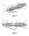
- FIG. 4A is a sectional perspective view of the reversible fiber connector of FIG. 1 with the mechanical sliding splice in a released position and the fiber in a final position in accordance with an illustrative embodiment of the present invention
- FIG. 4B is a front side view of the reversible fiber connector of FIG. 4A in accordance with an illustrative embodiment of the present invention
- FIG. 5A is a sectional perspective view of the reversible fiber connector of FIG. 1 with the mechanical sliding splice in an intermediate position and the fiber in a final position in accordance with an illustrative embodiment of the present invention
- FIG. 5B is a front side view of the reversible fiber connector of FIG. 5A in accordance with an illustrative embodiment of the present invention
- FIG. 6A is a sectional perspective view of the reversible fiber connector of FIG. 1 with the mechanical sliding splice in a clamping position and the fiber in a final position in accordance with an illustrative embodiment of the present invention.
- FIG. 6B is a front side view of the reversible fiber connector of FIG. 6A in accordance with an illustrative embodiment of the present invention.
- the connector 10 is illustratively a re-terminable, no-crimp Local Connector (LC)-type optical connector that comprises a housing 12 having a front end, in which a ferrule 14 having affixed thereto an optical fiber stub 16 is received.
- the connector 10 further comprises at a rear end thereof opposite the ferrule 14 a backbone 18 through which a mating optical fiber 20 is inserted into the connector 10 along the direction of arrow A for termination.
- LC Local Connector
- the optical fiber 20 is illustratively prepared for insertion into the connector 10 by removing a portion of the cable jacket 22 and coated or buffered portion 24 to expose a predetermined length of the bare glass fiber 20 .
- a tab 26 is further provided on a lower surface (not shown) of the connector 10 for insertion and retention thereof into an appropriately configured port of a patch panel or other device (both not shown) to permit signals to pass from the optical fiber 20 to the device and vice-versa.
- the connector housing 12 is illustratively elongate and comprises a cavity (not shown) extending between the front and rear ends of the connector 10 along a longitudinal axis X.
- An elongate ferrule holder 28 is disposed in the housing cavity and surrounds the end of the ferrule 14 , in which the fiber stub 16 is received for retention thereof.
- the housing 12 further comprises a clamping mechanism mounted to the ferrule holder 28 for termination of the fibers 16 , 20 and comprising a first mechanical splice anvil 30 used to maintain the fiber stub 16 and the optical fiber 20 in alignment as well as a second mechanical splice anvil 32 positioned adjacent the first anvil 30 along the axis X and used to exert pressure on the buffered portion 24 and on the bare fiber 20 , as will be discussed in further detail herein below.
- the first and second anvils 30 , 32 are illustratively slidably mounted about the ferrule holder 28 for independent movement along the axis X towards the front end of the connector 10 (i.e. along the direction of arrow B).
- the anvils 30 , 32 are moveable from a released position (illustrated in FIG. 2A ), in which no pressure is applied by the anvils 30 , 32 and the fiber 20 can be freely inserted through the rear end of the connector 10 for mating with the fiber stub 16 , to a clamping (or clamped) position (illustrated in FIG. 2B ), in which radial pressure is applied by the anvils 30 , 32 on the fiber stub 16 and the optical fiber 20 as well as on the buffered portion 24 to ensure proper mating and alignment of a stub splicing face (not shown) of the fiber stub 16 with an optical fiber splicing face (not shown) of the optical fiber 20 for accurate termination.
- the anvils 30 , 32 are each surrounded by a slit sleeve spring 34 , which ensures that the pressure applied by the anvils 30 , 32 on the fibers 16 , 20 and on the buffered portion 24 of the cable 22 is maintained when the anvils 30 , 32 are moved to the clamping position.
- projections as in 35 are illustratively provided thereon, thus facilitating actuation of the clamping mechanism.
- an alignment groove (V-shaped or “V-groove”) 36 is illustratively provided on a substantially flat inner surface of the ferrule holder 28 and extends between front and rear ends of the ferrule holder 28 along the axis X.
- the groove 36 has at each end thereof a funnel-shaped lead-in portion 38 1 , 38 2 , which provides a smooth transition for the fibers 16 and 20 to be routed into the groove 36 from either end of the connector 10 , thus protecting the end face (not shown) of the fibers 16 , 20 from damage.
- the alignment groove 36 could have any other shape (e.g. square or “U-groove”) suitable for receiving and aligning the fiber stub 16 and the adjoining optical fiber 20 within the connector 10 .
- the connector 10 may be provided with a plurality of alignment grooves as in 36 to accommodate a dual-fiber or multi-fiber connector having two (2) or more fiber stubs as in 16 .
- the first groove portion 38 1 is illustratively positioned adjacent the ferrule 14 to facilitate the positioning and centering of the fiber stub 16 inside the ferrule 14 and of a protruding end (not shown) of the fiber stub 16 within the groove 36 .
- the ferrule 14 illustratively comprises an axial bore (not shown), which is aligned with the groove 36 and in which the fiber stub 16 is disposed with the protruding end extending away from the front end of the housing 12 .
- the second groove portion 38 2 is used to position the buffered portion 24 and accordingly insert and advance the fiber 20 freely within the connector housing 12 along the groove 36 (with the anvils 30 , 32 in the released position) until the fiber 20 reaches a final centered position (see FIGS. 4A and 4B ) and the optical fiber splicing face of the fiber 20 extends within the housing 12 from the rear end of the connector 10 towards the front end to make physical contact with the stub splicing face of the fiber stub 16 .
- index-matching gel may be provided in the area of the groove 36 where the fibers 16 and 20 mate to refractively limit signal loss at the interface of the optical fiber 16 and the fiber stub 20 once the latter are properly aligned.
- the anvils 30 , 32 are illustratively positioned adjacent the groove 36 , with a clamping surface (not shown) of the anvil 30 being adjacent the stub splicing face and the optical fiber splicing face of the adjoining fiber 20 and fiber stub 16 .
- the first mechanical anvil 30 is slid along the direction of arrow B towards the front end of the connector 10 away from the second anvil 32 (intermediate position illustrated in FIG. 5A and FIG. 5B ) until the anvil 30 reaches the clamping position (illustrated in FIG. 6A and FIG.
- the anvil 30 In the clamping position, the anvil 30 illustratively abuts against the front end (not shown) of the ferrule holder 28 . As a result, the clamping surface of the anvil 30 overlaps the area of the groove 36 where the stub splicing face and optical fiber splicing face of the stub fiber 16 and the optical fiber 20 mate and exerts a clamping force on the adjoining optical fiber 20 and fiber stub 16 , which are thereby compressed to better retain the fibers 16 and 20 in alignment relative to one another within the groove 36 .
- the second mechanical anvil 32 is also slid along the direction of arrow B towards the first anvil 30 to a clamping position.
- radial pressure is also applied on the buffered portion 24 of the cable 22 as well as on the optical fiber 20 to better retain the latter within the connector housing 12 .
- the optical fiber 20 is thus more accurately terminated and the connector 10 can subsequently be mated to an appropriate port or other connector (both not shown).
- a spring 40 illustratively provides compressive resistance behind the ferrule 14 , thus ensuring adequate contact pressure between the ferrule 14 and a contact point on the port.
- the flat inner surface of the ferrule holder 28 further comprises a plurality of step surfaces as in 42 , which cooperate with the splice anvils 30 , 32 to effect the clamping mechanism that urges the clamping surfaces of the anvils 30 , 32 against the adjoining fiber stub 16 and optical fiber 20 as the anvils 30 , 32 are slid along directional arrow B, as discussed herein above.
- the anvils 30 , 32 are illustratively slidably mounted on the step surfaces 42 such that, as the anvils 30 , 32 are displaced along the axis (reference X in FIG.
- the anvils 30 , 32 are moved downwardly (or alternatively upwardly if the anvils 30 , 32 are displaced in the direction opposite to that of arrow B) and closer to (or further away from) the inner surface of the ferrule holder 28 along a direction perpendicular to the axis X. Accordingly, the clamping surfaces of the anvils 30 , 32 are positioned closer to (or further away from) the groove 36 , in which the adjoining fibers 16 , 20 are retained.
- the mechanical movement provided by the step surfaces as in 42 therefore advantageously allows to adjust (i.e. add or remove) the amount of radial pressure applied by the anvils 30 , 32 on the adjoining fibers 16 , 20 by enabling the anvils 30 , 32 to move upward or downward along the step surfaces as in 42 .
- the termination mechanism of the present invention has the added advantage of being simple as well as non-destructively reusable. This is effected by returning the slit sleeve spring 34 and associated anvils 30 , 32 to the original released position, thus releasing clamping forces on both the optical fiber 20 and the fiber stub 16 . The optical fiber 20 may then be withdrawn from the connector 10 (after having been terminated) and subsequently reinserted for another attempt at a successful connection in the event where optical continuity between the fibers 16 and 20 has been deemed unacceptable.
- the connector 10 therefore eliminates the need for any extra and irreversible operation to crimp a lead-in tube or annular crimp ring about the buffered portion 24 of the fiber cable 22 and provide strain relief to the interface of the aligned fiber stub 16 and field fiber 20 , as is the case of conventional connectors.
- the assembly of the present invention is advantageously adaptable to various types of fiber connectors, such as fiber connectors conformed to the Straight Tip (ST), Standard Connector (SC), or hybrid fiber and electrical contact standards.
- fiber connectors conformed to the Straight Tip (ST), Standard Connector (SC), or hybrid fiber and electrical contact standards.
- ST Straight Tip
- SC Standard Connector
- hybrid fiber and electrical contact standards such as fiber connectors conformed to the Straight Tip (ST), Standard Connector (SC), or hybrid fiber and electrical contact standards.
- ST Straight Tip
- SC Standard Connector
Landscapes
- Physics & Mathematics (AREA)
- General Physics & Mathematics (AREA)
- Optics & Photonics (AREA)
- Mechanical Coupling Of Light Guides (AREA)
Abstract
Description
Claims (19)
Priority Applications (1)
| Application Number | Priority Date | Filing Date | Title |
|---|---|---|---|
| US12/489,793 US8075198B2 (en) | 2008-06-23 | 2009-06-23 | Reversible fiber connector with mechanical sliding splice |
Applications Claiming Priority (2)
| Application Number | Priority Date | Filing Date | Title |
|---|---|---|---|
| US7482308P | 2008-06-23 | 2008-06-23 | |
| US12/489,793 US8075198B2 (en) | 2008-06-23 | 2009-06-23 | Reversible fiber connector with mechanical sliding splice |
Publications (2)
| Publication Number | Publication Date |
|---|---|
| US20090317037A1 US20090317037A1 (en) | 2009-12-24 |
| US8075198B2 true US8075198B2 (en) | 2011-12-13 |
Family
ID=41431391
Family Applications (1)
| Application Number | Title | Priority Date | Filing Date |
|---|---|---|---|
| US12/489,793 Active 2030-06-09 US8075198B2 (en) | 2008-06-23 | 2009-06-23 | Reversible fiber connector with mechanical sliding splice |
Country Status (1)
| Country | Link |
|---|---|
| US (1) | US8075198B2 (en) |
Cited By (2)
| Publication number | Priority date | Publication date | Assignee | Title |
|---|---|---|---|---|
| US9690065B2 (en) | 2014-09-12 | 2017-06-27 | Panduit Corp. | High density fiber enclosure and method |
| US10215944B2 (en) | 2016-06-30 | 2019-02-26 | Panduit Corp. | Modular fiber optic tray |
Families Citing this family (5)
| Publication number | Priority date | Publication date | Assignee | Title |
|---|---|---|---|---|
| TWM403667U (en) * | 2010-10-29 | 2011-05-11 | Hon Hai Prec Ind Co Ltd | Fiber connector |
| US8734028B2 (en) * | 2011-05-25 | 2014-05-27 | Tyco Electronics Corporation | Tool-less clamping mechanism |
| US8596884B2 (en) | 2011-06-28 | 2013-12-03 | Corning Cable Systems Llc | Optical fiber mechanical splice connector systems and methods of coupling optical fibers |
| US9124010B2 (en) | 2011-11-30 | 2015-09-01 | Ppc Broadband, Inc. | Coaxial cable connector for securing cable by axial compression |
| US8657506B2 (en) * | 2011-12-20 | 2014-02-25 | Tyco Electronics Corporation | Field terminating method and device |
Citations (20)
| Publication number | Priority date | Publication date | Assignee | Title |
|---|---|---|---|---|
| US4435038A (en) | 1981-01-14 | 1984-03-06 | Amp Incorporated | Connector for use in butt splicing two optical fibres |
| US4669820A (en) | 1982-06-05 | 1987-06-02 | Amp Incorporated | Optical fiber termination method, terminal splice and connector therefor |
| US5138681A (en) | 1988-04-18 | 1992-08-11 | Minnesota Mining And Manufacturing Company | Optical fiber splice |
| US5341448A (en) | 1992-07-30 | 1994-08-23 | Advanced Custom Applications, Inc. | Optical fiber splice |
| US5394496A (en) | 1993-12-08 | 1995-02-28 | Northern Telecom Limited | Optical fiber mechanical splice |
| US5984532A (en) | 1995-08-24 | 1999-11-16 | Fujikura Ltd. | Optical fiber connector |
| US6179482B1 (en) | 1997-01-16 | 2001-01-30 | Fujikura, Ltd. | Optical connector and housing for optical connector |
| US6379054B2 (en) | 1998-07-01 | 2002-04-30 | Corning Cable Systems Llc | Field installable multifiber connector |
| US6604867B2 (en) | 2001-10-23 | 2003-08-12 | Panduit Corp. | Fiber optic connector |
| US7001084B2 (en) | 2003-12-30 | 2006-02-21 | 3M Innovative Properties Company | Fiber splice device |
| US7014372B2 (en) | 2001-10-04 | 2006-03-21 | Tyco Electronics Raychem Nv | Method and apparatus for splicing optical fibres |
| US20060153515A1 (en) | 2003-02-17 | 2006-07-13 | Toshihiko Honma | Optical fiber connecting tool |
| US7178990B2 (en) | 2003-08-25 | 2007-02-20 | Panduit Corp. | Reversible fiber optic stub fiber clamping mechanism |
| US7241056B1 (en) | 2006-06-13 | 2007-07-10 | Panduit Corp. | Reversible fiber optic connector |
| US7258496B2 (en) | 2002-02-08 | 2007-08-21 | Fujikura Ltd. | Optical fiber connection tool and optical fiber connection method |
| US7264410B1 (en) | 2006-03-16 | 2007-09-04 | Corning Cable Systems Llc | Dual function splice component for mechanical splice connector |
| US7280733B2 (en) | 2005-10-24 | 2007-10-09 | 3M Innovative Properties Company | Fiber termination platform for optical connectors |
| US7346256B2 (en) | 2004-11-04 | 2008-03-18 | Panduit Corp. | Re-terminable LC connector assembly and cam termination tool |
| US20080075407A1 (en) | 2006-09-27 | 2008-03-27 | Fujikura Ltd. | Optical connector |
| US7887244B2 (en) * | 2008-06-13 | 2011-02-15 | Belden Cdt (Canada) Inc. | Reversible fiber connector with mechanical splice and sliding lock |
-
2009
- 2009-06-23 US US12/489,793 patent/US8075198B2/en active Active
Patent Citations (20)
| Publication number | Priority date | Publication date | Assignee | Title |
|---|---|---|---|---|
| US4435038A (en) | 1981-01-14 | 1984-03-06 | Amp Incorporated | Connector for use in butt splicing two optical fibres |
| US4669820A (en) | 1982-06-05 | 1987-06-02 | Amp Incorporated | Optical fiber termination method, terminal splice and connector therefor |
| US5138681A (en) | 1988-04-18 | 1992-08-11 | Minnesota Mining And Manufacturing Company | Optical fiber splice |
| US5341448A (en) | 1992-07-30 | 1994-08-23 | Advanced Custom Applications, Inc. | Optical fiber splice |
| US5394496A (en) | 1993-12-08 | 1995-02-28 | Northern Telecom Limited | Optical fiber mechanical splice |
| US5984532A (en) | 1995-08-24 | 1999-11-16 | Fujikura Ltd. | Optical fiber connector |
| US6179482B1 (en) | 1997-01-16 | 2001-01-30 | Fujikura, Ltd. | Optical connector and housing for optical connector |
| US6379054B2 (en) | 1998-07-01 | 2002-04-30 | Corning Cable Systems Llc | Field installable multifiber connector |
| US7014372B2 (en) | 2001-10-04 | 2006-03-21 | Tyco Electronics Raychem Nv | Method and apparatus for splicing optical fibres |
| US6604867B2 (en) | 2001-10-23 | 2003-08-12 | Panduit Corp. | Fiber optic connector |
| US7258496B2 (en) | 2002-02-08 | 2007-08-21 | Fujikura Ltd. | Optical fiber connection tool and optical fiber connection method |
| US20060153515A1 (en) | 2003-02-17 | 2006-07-13 | Toshihiko Honma | Optical fiber connecting tool |
| US7178990B2 (en) | 2003-08-25 | 2007-02-20 | Panduit Corp. | Reversible fiber optic stub fiber clamping mechanism |
| US7001084B2 (en) | 2003-12-30 | 2006-02-21 | 3M Innovative Properties Company | Fiber splice device |
| US7346256B2 (en) | 2004-11-04 | 2008-03-18 | Panduit Corp. | Re-terminable LC connector assembly and cam termination tool |
| US7280733B2 (en) | 2005-10-24 | 2007-10-09 | 3M Innovative Properties Company | Fiber termination platform for optical connectors |
| US7264410B1 (en) | 2006-03-16 | 2007-09-04 | Corning Cable Systems Llc | Dual function splice component for mechanical splice connector |
| US7241056B1 (en) | 2006-06-13 | 2007-07-10 | Panduit Corp. | Reversible fiber optic connector |
| US20080075407A1 (en) | 2006-09-27 | 2008-03-27 | Fujikura Ltd. | Optical connector |
| US7887244B2 (en) * | 2008-06-13 | 2011-02-15 | Belden Cdt (Canada) Inc. | Reversible fiber connector with mechanical splice and sliding lock |
Cited By (15)
| Publication number | Priority date | Publication date | Assignee | Title |
|---|---|---|---|---|
| US10698171B2 (en) | 2014-09-12 | 2020-06-30 | Panduit Corp. | High density fiber enclosure and method |
| US11624888B2 (en) | 2014-09-12 | 2023-04-11 | Panduit Corp. | High density fiber enclosure and method |
| US12228782B2 (en) | 2014-09-12 | 2025-02-18 | Panduit Corp. | High density fiber enclosure and method |
| US10268013B2 (en) | 2014-09-12 | 2019-04-23 | Panduit Corp. | High density fiber enclosure and method |
| US10317637B2 (en) | 2014-09-12 | 2019-06-11 | Panduit Corp. | High density fiber enclosure and method |
| US10606013B2 (en) | 2014-09-12 | 2020-03-31 | Panduit Corp. | High density fiber enclosure and method |
| US9864158B2 (en) | 2014-09-12 | 2018-01-09 | Panduit Corp. | High density fiber enclosure and method |
| US10768385B2 (en) | 2014-09-12 | 2020-09-08 | Panduit Corp. | High density fiber enclosure and method |
| US9690065B2 (en) | 2014-09-12 | 2017-06-27 | Panduit Corp. | High density fiber enclosure and method |
| US11105995B2 (en) | 2014-09-12 | 2021-08-31 | Panduit Corp. | High density fiber enclosure and method |
| US11372185B2 (en) | 2016-06-30 | 2022-06-28 | Panduit Corp. | Modular fiber optic tray |
| US10725258B2 (en) | 2016-06-30 | 2020-07-28 | Panduit Corp. | Modular fiber optic tray |
| US11709331B2 (en) | 2016-06-30 | 2023-07-25 | Panduit Corp. | Modular fiber optic tray |
| US12105338B2 (en) | 2016-06-30 | 2024-10-01 | Panduit Corp. | Modular fiber optic tray |
| US10215944B2 (en) | 2016-06-30 | 2019-02-26 | Panduit Corp. | Modular fiber optic tray |
Also Published As
| Publication number | Publication date |
|---|---|
| US20090317037A1 (en) | 2009-12-24 |
Similar Documents
| Publication | Publication Date | Title |
|---|---|---|
| US7811006B2 (en) | Field installable fiber optic connector and installation tool | |
| US11874510B2 (en) | Optical assembly with cable retainer | |
| US8801298B2 (en) | Slide actuated field installable fiber optic connector | |
| US11906789B2 (en) | Optical waveguide positioning feature in a multiple waveguides connector | |
| US7264410B1 (en) | Dual function splice component for mechanical splice connector | |
| US8075198B2 (en) | Reversible fiber connector with mechanical sliding splice | |
| US7594764B2 (en) | Field-installable fusion spliced fiber optic connector kits and methods therefor | |
| US7331719B2 (en) | Optical fiber clamping assembly | |
| US11934019B2 (en) | Dust mitigating optical connector | |
| US7461983B1 (en) | Field-installable optical splice | |
| US20070217745A1 (en) | Mechanical splice connector with sequential splice and strain relief | |
| US7887244B2 (en) | Reversible fiber connector with mechanical splice and sliding lock | |
| US20090252458A1 (en) | Optical attenuator | |
| US8734028B2 (en) | Tool-less clamping mechanism | |
| US11487062B2 (en) | Field assembly optical connector configured to prevent optical fiber bending | |
| EP1054277A2 (en) | Apparatus and method for interconnecting optical fibers | |
| US20190278025A1 (en) | Connector loader | |
| US20230314713A1 (en) | Optical connector and method of manufacturing optical connector | |
| JP2896860B2 (en) | Optical multi-core connector | |
| JP4576163B2 (en) | Optical connection method |
Legal Events
| Date | Code | Title | Description |
|---|---|---|---|
| AS | Assignment |
Owner name: BELDEN CDT(CANADA) INC., CANADA Free format text: NUNC PRO TUNC ASSIGNMENT;ASSIGNORS:MILETTE, LUC;LEVY, MOISE;REEL/FRAME:023158/0023;SIGNING DATES FROM 20090730 TO 20090731 Owner name: BELDEN CDT(CANADA) INC., CANADA Free format text: NUNC PRO TUNC ASSIGNMENT;ASSIGNORS:MILETTE, LUC;LEVY, MOISE;SIGNING DATES FROM 20090730 TO 20090731;REEL/FRAME:023158/0023 |
|
| STCF | Information on status: patent grant |
Free format text: PATENTED CASE |
|
| FEPP | Fee payment procedure |
Free format text: PAYOR NUMBER ASSIGNED (ORIGINAL EVENT CODE: ASPN); ENTITY STATUS OF PATENT OWNER: LARGE ENTITY |
|
| FPAY | Fee payment |
Year of fee payment: 4 |
|
| MAFP | Maintenance fee payment |
Free format text: PAYMENT OF MAINTENANCE FEE, 8TH YEAR, LARGE ENTITY (ORIGINAL EVENT CODE: M1552); ENTITY STATUS OF PATENT OWNER: LARGE ENTITY Year of fee payment: 8 |
|
| AS | Assignment |
Owner name: BELDEN CANADA INC., CANADA Free format text: MERGER AND CHANGE OF NAME;ASSIGNORS:BELDEN CDT (CANADA) INC.;MIRANDA TECHNOLOGIES ULC;BYRES SECURITY ULC;AND OTHERS;REEL/FRAME:054550/0751 Effective date: 20121101 Owner name: BELDEN CANADA ULC, CANADA Free format text: ASSIGNMENT OF ASSIGNORS INTEREST;ASSIGNOR:BELDEN CANADA INC.;REEL/FRAME:054592/0263 Effective date: 20200320 |
|
| MAFP | Maintenance fee payment |
Free format text: PAYMENT OF MAINTENANCE FEE, 12TH YEAR, LARGE ENTITY (ORIGINAL EVENT CODE: M1553); ENTITY STATUS OF PATENT OWNER: LARGE ENTITY Year of fee payment: 12 |