WO2020084971A1 - 異材接合用アーク溶接法、接合補助部材、異材溶接継手、及び、接合補助部材付き板材 - Google Patents
異材接合用アーク溶接法、接合補助部材、異材溶接継手、及び、接合補助部材付き板材 Download PDFInfo
- Publication number
- WO2020084971A1 WO2020084971A1 PCT/JP2019/036831 JP2019036831W WO2020084971A1 WO 2020084971 A1 WO2020084971 A1 WO 2020084971A1 JP 2019036831 W JP2019036831 W JP 2019036831W WO 2020084971 A1 WO2020084971 A1 WO 2020084971A1
- Authority
- WO
- WIPO (PCT)
- Prior art keywords
- plate
- joining
- diameter
- hole
- auxiliary member
- Prior art date
Links
Images


Classifications
-
- B—PERFORMING OPERATIONS; TRANSPORTING
- B23—MACHINE TOOLS; METAL-WORKING NOT OTHERWISE PROVIDED FOR
- B23K—SOLDERING OR UNSOLDERING; WELDING; CLADDING OR PLATING BY SOLDERING OR WELDING; CUTTING BY APPLYING HEAT LOCALLY, e.g. FLAME CUTTING; WORKING BY LASER BEAM
- B23K10/00—Welding or cutting by means of a plasma
- B23K10/02—Plasma welding
-
- B—PERFORMING OPERATIONS; TRANSPORTING
- B23—MACHINE TOOLS; METAL-WORKING NOT OTHERWISE PROVIDED FOR
- B23K—SOLDERING OR UNSOLDERING; WELDING; CLADDING OR PLATING BY SOLDERING OR WELDING; CUTTING BY APPLYING HEAT LOCALLY, e.g. FLAME CUTTING; WORKING BY LASER BEAM
- B23K9/00—Arc welding or cutting
- B23K9/007—Spot arc welding
-
- B—PERFORMING OPERATIONS; TRANSPORTING
- B23—MACHINE TOOLS; METAL-WORKING NOT OTHERWISE PROVIDED FOR
- B23K—SOLDERING OR UNSOLDERING; WELDING; CLADDING OR PLATING BY SOLDERING OR WELDING; CUTTING BY APPLYING HEAT LOCALLY, e.g. FLAME CUTTING; WORKING BY LASER BEAM
- B23K9/00—Arc welding or cutting
- B23K9/14—Arc welding or cutting making use of insulated electrodes
-
- B—PERFORMING OPERATIONS; TRANSPORTING
- B23—MACHINE TOOLS; METAL-WORKING NOT OTHERWISE PROVIDED FOR
- B23K—SOLDERING OR UNSOLDERING; WELDING; CLADDING OR PLATING BY SOLDERING OR WELDING; CUTTING BY APPLYING HEAT LOCALLY, e.g. FLAME CUTTING; WORKING BY LASER BEAM
- B23K9/00—Arc welding or cutting
- B23K9/16—Arc welding or cutting making use of shielding gas
- B23K9/167—Arc welding or cutting making use of shielding gas and of a non-consumable electrode
-
- B—PERFORMING OPERATIONS; TRANSPORTING
- B23—MACHINE TOOLS; METAL-WORKING NOT OTHERWISE PROVIDED FOR
- B23K—SOLDERING OR UNSOLDERING; WELDING; CLADDING OR PLATING BY SOLDERING OR WELDING; CUTTING BY APPLYING HEAT LOCALLY, e.g. FLAME CUTTING; WORKING BY LASER BEAM
- B23K9/00—Arc welding or cutting
- B23K9/16—Arc welding or cutting making use of shielding gas
- B23K9/173—Arc welding or cutting making use of shielding gas and of a consumable electrode
-
- B—PERFORMING OPERATIONS; TRANSPORTING
- B23—MACHINE TOOLS; METAL-WORKING NOT OTHERWISE PROVIDED FOR
- B23K—SOLDERING OR UNSOLDERING; WELDING; CLADDING OR PLATING BY SOLDERING OR WELDING; CUTTING BY APPLYING HEAT LOCALLY, e.g. FLAME CUTTING; WORKING BY LASER BEAM
- B23K9/00—Arc welding or cutting
- B23K9/23—Arc welding or cutting taking account of the properties of the materials to be welded
-
- B—PERFORMING OPERATIONS; TRANSPORTING
- B23—MACHINE TOOLS; METAL-WORKING NOT OTHERWISE PROVIDED FOR
- B23K—SOLDERING OR UNSOLDERING; WELDING; CLADDING OR PLATING BY SOLDERING OR WELDING; CUTTING BY APPLYING HEAT LOCALLY, e.g. FLAME CUTTING; WORKING BY LASER BEAM
- B23K9/00—Arc welding or cutting
- B23K9/235—Preliminary treatment
Definitions
- the present invention relates to an arc welding method for joining dissimilar materials, a joining auxiliary member, a dissimilar material welded joint, and a plate material with a joining auxiliary member.
- Patent Document 1 Although the joining method described in Patent Document 1 is a relatively easy method, when the strength of the steel is high, there is a problem that the caulking member cannot be inserted, and the joining strength depends on the frictional force and the caulking member. Since it depends on the rigidity, there is a problem that high joint strength cannot be obtained. Further, when inserting the caulking member, there is a problem that it cannot be applied to the closed cross-section structure because it is necessary to press the caulking member from both the front and back sides with a jig.
- Patent Document 2 cannot be applied to the closed cross-section structure, and the resistance welding method has a problem that the equipment is very expensive.
- Patent Document 3 applies pressure to the steel material surface while plastically flowing the aluminum alloy material in the low temperature region, so that both materials do not melt and prevent the formation of intermetallic compounds. It is said that a metal bonding force can be obtained, and there are also research results that steel and carbon fibers can be joined. However, this joining method is also not applicable to a closed cross-section structure and requires high pressure, so that it is mechanically large and expensive. Also, the joining force does not become so high.
- the existing dissimilar material joining technology has one or more problems such as (i) the members and the groove shape are limited to the open cross-section structure, (ii) the joining strength is low, and (iii) the equipment cost is high. have. Therefore, in order to popularize the multi-material design in which various materials are combined, (i ') applicable to both open cross-section structure and closed cross-section structure, (ii') sufficiently high bonding strength and reliability. There is a demand for a new technology that is easy to use and has all the elements of high cost (iii ') and low cost.
- the present invention has been made in view of the above-mentioned problems, and an object thereof is to dissimilar materials of aluminum alloy (hereinafter also referred to as “Al alloy”) or magnesium alloy (hereinafter also referred to as “Mg alloy”) and steel, Arc welding method for joining dissimilar materials, joining that can be joined with strong and reliable quality using inexpensive arc welding equipment already popular in the world, and can be applied to open cross-section structure and closed cross-section structure without restriction
- An object is to provide an auxiliary member, a dissimilar material welded joint, and a plate member with a joining auxiliary member.
- intermetallic compounds IMC
- welding of steels shows the highest joint strength and reliability. Therefore, the inventors of the present invention have devised a means for achieving welding of dissimilar materials by using welding of steels as a joining force and further utilizing a restraining force.
- An arc welding method for joining dissimilar materials which joins a first plate made of an aluminum alloy or a magnesium alloy and a second plate made of steel, Forming a circular hole in the first plate, It has a stepped outer shape having a shaft portion and a flange portion, at least one press-fitting protrusion portion is provided on the outer peripheral surface of the shaft portion, and a hollow portion penetrating the shaft portion and the flange portion is provided.
- the width of the flange portion is larger than the diameter of the hole of the first plate, and the diameter of the largest circle in contact with the outermost diameter portion of at least two of the protrusions, or the maximum diameter of one of the protrusions.
- B A non-gas arc welding method using the welding wire as a welding electrode.
- C A gas tungsten arc welding method using the welding wire as a non-electrolytic electrode filler.
- D A plasma arc welding method using the welding wire as a non-electrolytic electrode filler.
- E A coated arc welding method in which a coated arc welding rod from which the above-mentioned weld metal of an iron alloy or a Ni alloy is obtained is used as a welding electrode.
- a preferred embodiment of the present invention related to the arc welding method for joining dissimilar materials relates to the following (2) to (11).
- (2) A bulging portion is formed on the second plate by drawing, The arc welding method for joining dissimilar materials according to (1), wherein the bulging portion of the second plate is arranged in the hole of the first plate in the superposing step.
- the arc welding method for joining dissimilar materials according to (1) or (2) further comprising: (4) In the press-fitting step, an adhesive is applied to at least one opposing surface between the joining auxiliary member and the first plate facing the joining auxiliary member, (1) to (3) An arc welding method for joining dissimilar materials according to any one of 1. (5) Any of (1) to (4), wherein an adhesive is applied to the boundary between the joining auxiliary member and the surface of the first plate during the press-fitting step or after the filling and welding step. An arc welding method for joining dissimilar materials according to Crab.
- the height P H1 of the shaft portion of the joining auxiliary member is 10% or more and 100% or less of the plate thickness B H of the first plate, according to any one of (1) to (5) Arc welding method for joining dissimilar materials.
- the maximum diameter circle P D1 in contact with the outermost diameter of the at least two protrusions or the diameter P D1 of a circle in contact with the outer peripheral surface of the the outermost diameter of said one protrusion shank The arc welding method for joining dissimilar materials according to any one of (1) to (6), wherein the diameter B D of the hole of the first plate is 105% or more and 125% or less.
- the outer diameter P D0 of the shaft portion of the joining assisting member is 80% or more and 104% or less with respect to the diameter B D of the hole of the first plate.
- Arc welding method for joining dissimilar materials as described.
- Arc welding method. (10)
- the thickness P H2 of the flange portion of the joining auxiliary member is 50% or more and 150% or less of the plate thickness B H of the first plate, according to any one of (1) to (9). Arc welding method for joining dissimilar materials.
- the above object of the present invention is achieved by the following configuration (12) of the joining auxiliary member.
- a hollow portion is formed, the maximum outer diameter of the shaft portion and the width of the flange portion are each larger than the diameter of the hole of the first plate, and the maximum outer diameter portion of at least two of the protrusion portions is in contact with the maximum outer diameter portion.
- a joining assisting member wherein a diameter of a circle, or a diameter of a circle in contact with the outermost diameter portion of one of the protrusions and the outer peripheral surface of the shaft portion is larger than the diameter of the hole of the first plate.
- a dissimilar material welded joint comprising: a first plate made of an aluminum alloy or a magnesium alloy; and a second plate made of steel which is arc-welded to the first plate,
- the first plate has a circular hole facing the overlapping surface with the second plate, It has a stepped outer shape having a shaft portion and a flange portion, at least one press-fitting protrusion portion is provided on the outer peripheral surface of the shaft portion, and a hollow portion penetrating the shaft portion and the flange portion is provided.
- the width of the flange portion is larger than the diameter of the hole of the first plate, and the diameter of the largest circle in contact with the outermost diameter portion of at least two of the protrusions, or the maximum diameter of one of the protrusions.
- a preferred embodiment of the present invention relating to a dissimilar material welded joint relates to the following (14) to (23).
- (14) The dissimilar material welded joint according to (13), wherein the bulging portion formed on the second plate is arranged in the hole of the first plate.
- At least one of the first plate and the second plate is provided with an adhesive that is provided over the entire circumference of the overlapping surface around the hole, (13) or (14) ) Dissimilar material welded joint.
- an adhesive is provided on at least one opposing surface between the joining auxiliary member and the first plate facing the joining auxiliary member. Dissimilar material welded joint described.
- the above object of the present invention is achieved by the following constitution (24) of the plate member with a joining auxiliary member.
- a plate material with a joining auxiliary member capable of forming a dissimilar material welded joint by arc welding with a steel plate material A plate material made of an aluminum alloy or a magnesium alloy having a circular hole, It has a stepped outer shape having a shaft portion and a flange portion, at least one press-fitting protrusion portion is provided on the outer peripheral surface of the shaft portion, and is a hollow that penetrates the shaft portion and the flange portion.
- the width of the flange part is larger than the diameter of the hole of the plate material, and the diameter of the largest circle in contact with the outermost diameter part of at least two of the protrusions, or the outermost part of one of the protrusions.
- a diameter of a circle contacting the outer peripheral surface of the diameter portion and the shaft portion is larger than the diameter of the hole of the first plate, the joining auxiliary member made of steel, The plate member with a joining auxiliary member, wherein the joining auxiliary member is attached to the plate member by press-fitting the press-fitting protrusion into a hole provided in the plate member.
- a dissimilar material of aluminum alloy or magnesium alloy and steel can be joined with strong and reliable quality by using inexpensive arc welding equipment, and can be applied to both open-section structure and closed-section structure. It can be applied without restrictions.
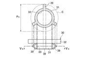
- FIG. 1B is a cross-sectional view of the dissimilar material welded joint taken along the line II of FIG. 1A. It is a perspective view of the joining auxiliary member of this embodiment.
- FIG. 3 is a side view of a joining assisting member of the present embodiment and a sectional view taken along line II-II. It is a principal part side view of the 1st modification of a joining auxiliary member. It is a principal part side view of the 2nd modification of a joining auxiliary member. It is a principal part side view of the 3rd modification of a joining assistance member. It is a principal part side view of the 4th modification of a joining auxiliary member.
- 1B of the dissimilar material welding joint using the joining auxiliary member of the 17th modification It is a front view of the 18th modification of a joining auxiliary member. It is a front view of the 19th modification of a joining auxiliary member. It is a front view of the 20th modification of a joining auxiliary member. It is a front view of the 21st modification of a joining auxiliary member. It is a figure which shows the drilling operation of the arc welding method for joining dissimilar materials of embodiment. It is a figure which shows the press-fitting work of the arc welding method for dissimilar material joining of embodiment. It is a figure which shows the superposition work of the arc welding method for different material joining of embodiment.
- FIG. 9A It is a figure which shows the welding operation of the arc welding method for dissimilar material joining of embodiment. It is sectional drawing which shows the dissimilar material welded joint in which excess is not formed. It is sectional drawing which shows the state which the external stress of the board thickness direction (three-dimensional direction) acted on the dissimilar material welded joint of FIG. 9A. It is sectional drawing which shows the state which the external stress of the plate thickness direction (three-dimensional direction) acted on the dissimilar material welded joint in which the extra heap was formed. It is a sectional view of a dissimilar material welding joint for explaining penetration of welding metal. It is a sectional view of a dissimilar material welding joint for explaining penetration of welding metal.
- FIG. 12B is a cross-sectional view showing a state where shear tension acts on the dissimilar material welded joint of FIG. 12A.
- FIG. 13A shows the dissimilar material welding joint of FIG. 13A.
- FIG. 14A shows the dissimilar material welded joint of FIG. 14A.
- FIG. 15A is a perspective view of the dissimilar material welding joint as a comparative example which carried out the penetration welding of the aluminum upper plate which has a hole, and the steel lower plate.
- FIG. 15B is a cross-sectional view showing a state where shear tension acts on the dissimilar material welded joint of FIG. 15A.
- FIG. 15B is a perspective view showing a state where shear tension acts on the dissimilar material welded joint of FIG. 15A and the joint portion is displaced by nearly 90 °.
- FIG. 17A It is a perspective view which shows the dissimilar material welded joint of FIG. 17A. It is sectional drawing of the dissimilar material welded joint of this embodiment. It is a perspective view which shows the state which the up-and-down peeling tension acted on the dissimilar material welded joint of FIG. 18A. It is sectional drawing which shows the state which shear tension acted on the dissimilar material welded joint of this embodiment. It is sectional drawing which shows the state which shear tension acted on the dissimilar material welded joint of this embodiment in which the intermetallic compound was produced. It is a sectional view of an upper plate, a lower plate, and a joining auxiliary member showing a state before an arc welding in which a gap exists between the upper plate and the lower plate.
- FIG. 6 is a cross-sectional view showing a state in which a stress in a shearing direction is applied to a dissimilar material welded joint using a joining auxiliary member having no protrusion and a shaft portion having a too small diameter.
- FIG. 22B is a cross-sectional view taken along the line XXII-XXII of FIG. 22A. It is a figure which shows the state in which arc welding is performed in the upward posture. It is a side view which shows the 22nd modification of a joining assistance member.
- FIG. 34 is a diagram showing a state before the bulging portion is drawn on the lower plate of FIG. 33.
- FIG. 34 is a diagram showing a state after the bulging portion is drawn on the lower plate of FIG. 33.
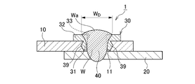
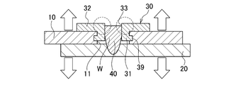
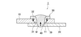
- the arc welding method for joining dissimilar materials of the present embodiment includes an upper plate 10 (first plate) made of an aluminum alloy or a magnesium alloy and a lower plate 20 (second plate) made of steel, which are superposed on each other.
- the welding of the dissimilar material welded joint 1 as shown in FIG. 1A and FIG. 1B is carried out by joining it by the arc welding method described later through the joining auxiliary member 30 made of steel.
- the upper plate 10 is provided with a circular hole 11 penetrating in the plate thickness direction and facing the overlapping surface of the lower plate 20, and the joining assisting member 30 is inserted into the hole 11 by applying pressure.
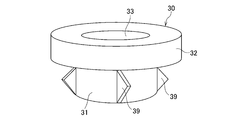
- the joining assisting member 30 is arranged on the shaft portion 31 arranged in the hole 11 of the upper plate 10 and on the upper surface of the upper plate 10 so as to face outward with respect to the shaft portion 31. It has a flanged portion 32 and a stepped outer shape having. Further, at least one (four in the present embodiment) press-fitting protrusions 39 are provided on the outer peripheral surface of the shaft portion 31.
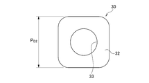
- the joining auxiliary member 30 is formed with a circular hollow portion 33 that penetrates the shaft portion 31 and the flange portion 32.
- the width P D2 of the flange portion 32 is set to be larger than the diameter B D of the hole 11 of the upper plate 10 (see FIG. 25A). Further, the diameter P D1 of the largest circle C that contacts the outermost diameter portion of the plurality of protrusions 39 is also set to be larger than the diameter B D of the hole 11 of the upper plate 10.
- the protrusion 39 fixes the shaft portion 31 of the joining assisting member 30 in the hole 11 of the upper plate 10 by caulking and restraining force, so that there is no gap between the shaft portion 31 and the hole 11 of the upper plate 10, and
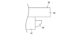
- the shaft portion 31 is formed in a blade shape in consideration of insertability. That is, the maximum outer diameter P D0 of the shaft portion 31 is made smaller than the diameter B D of the hole 11 of the upper plate 10, while the protrusion 39 is made to bite into the wall surface of the hole 11 of the upper plate 10 to partially Eliminate the gap. Further, in consideration of insertability, it is preferable that the shape of the protruding portion 39 gradually increase in radial width from the tip end portion of the shaft portion 31 toward the flange portion side. Furthermore, since the thickness of the protrusion 39 in the circumferential direction is small, the protrusion 39 is in a state close to a line contact with the hole 11 of the upper plate 10, and the pushing pressure is not so much increased.
- the shape of the protrusion 39 may be an isosceles triangle as shown in FIGS. 2A and 2B, but as shown in FIGS. 3A to 3I, other shapes such as triangle, rectangle, partial circle, and trapezoid are typical. And, there is no limit to its shape. Further, since the protrusion 39 is also connected to the lower surface of the flange 32, the strength of the protrusion 39 can be improved. Furthermore, the protrusion 39 may be parallel to the axial direction of the shaft 31 as shown in FIG. 2A, or may be inclined with respect to the axial direction as shown in FIG. 4A. In this case, it is suitable for press-fitting while rotating the joining auxiliary member 30. Further, as shown in FIG. 4B, the protrusion 39 may have a mountain shape whose width in the circumferential direction becomes narrower from the base to the tip.
- the number of the projections 39 is not limited to four as shown in FIG. 2, but may be at least one, and it is not necessary to set an upper limit. That is, as shown in FIGS. 5A to 5E, it may have one, two, three, six, and eight protrusions 39. However, if the number of protrusions 39 increases, the contact area with the holes 11 of the upper plate 10 increases and the pressure required for insertion increases, so the number of protrusions 39 should not be increased more than necessary. It is desirable that the number of protrusions 39 be 8 or less. In addition, as shown in FIG.
- the diameter P D1 of the circle C contacting the outermost diameter portion of one protrusion 39 and the outer peripheral surface of the shaft portion 31 is also the diameter of the upper plate 10. It is set larger than the diameter B D of the hole 11.
- the joining assisting member 30 can be designed by arbitrarily combining the number and shape of the above-mentioned protrusions 39.
- a joining assisting member 30 having three right triangular projections 39 may be configured.
- FIG. 6B is a cross-sectional view corresponding to FIG. 1B of the dissimilar material welded joint 1 when the joining assisting member 30 of FIG. 6A is used.
- the function of the protrusion 39 is substantially the same in any of the above-mentioned joining auxiliary members 30, the following description will be given using an arbitrary joining auxiliary member 30.
- the outer shape of the flange portion 32 of the joining auxiliary member 30 is not limited to the circular shape as shown in FIGS. 2A and 2B, and may be any shape as long as the hole 11 formed in the upper plate 10 is closed after welding. Can be For example, it may be a polygon having a quadrangle or more shown in FIGS. 7A to 7D. Further, as shown in FIG. 7B, the corners of the polygon may be rounded.
- the width P D2 of the flange portion 32 which will be described later, is defined by the shortest facing surface distance. When the flange portion 32 is circular, the outer diameter is the width P D2 of the flange portion 32.
- the joining assisting member 30 is press-fitted into the upper plate 10, so that the shaft portion 31 is fixed in the hole 11 of the upper plate 10.
- the shaft portion 31 and the hollow portion 33 are located coaxially with the hole 11 of the upper plate 10.
- one protrusion 39 is provided on the shaft portion 31, the shaft portion 31 and the hollow portion 33 are located offset from the holes 11 of the upper plate 10.
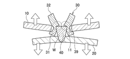
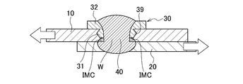
- the hollow portion 33 of the joining auxiliary member 30 is filled with the weld metal 40 of the iron alloy or the Ni alloy in which the filler material (welding material) is melted by arc welding, and is also melted with the weld metal 40.
- the lower plate 20 and a part of the joining auxiliary member 30 form a fusion zone W. Therefore, the fusion zone W is also arranged in the hole 11 of the upper plate 10 and welds the joining assisting member 30 and the lower plate 20, whereby the upper plate 10 and the lower plate 20 are joined. .
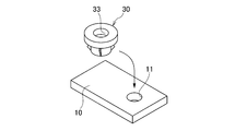
- FIG. 8A a hole 11 is punched in the upper plate 10 (step S1).
- step S2 the joining auxiliary member 30 is press-fitted into the hole 11 of the upper plate 10 from the upper surface of the upper plate 10 (step S2).
- step S3 the press-fitting projection 39 formed on the shaft portion 31 bites into the hole 11 of the upper plate 10 and is press-fitted.
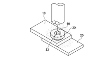
- step S3 a superposing operation for superposing the upper plate 10 and the lower plate 20 is performed (step S3). Then, as shown in FIG.
- Specific methods of the punching work in step S1 include a) punching using a punch, b) press die cutting using a die, c) cutting using a laser, plasma, water jet method or the like.
- step S4 the joining auxiliary member 30 and the lower plate 20 are joined via the weld metal 40 in the hole 11 of the upper plate 10, and the hollow portion 33 provided in the joining auxiliary member 30 is filled. Needed to do. Therefore, insertion of a filler material (welding material) as a filler is essential for arc welding. Specifically, the filler material is melted and the weld metal 40 is formed by the following four arc welding methods.
- the molten electrode gas shield arc welding method is a welding method generally called MAG (Metal Active Gas) or MIG (Metal Inert Gas), and uses a solid wire or a flux-cored wire as a filler / arc-generating molten electrode. It is a method of forming a sound weld by shielding the weld from the atmosphere with a shield gas such as CO 2 , O 2 , Ar, and He.
- MAG Metal Active Gas
- MIG Metal Inert Gas
- the non-gas arc welding method is also called a self-shielded arc welding method, which uses a special flux-cored wire as a filler and arc generating molten electrode, and on the other hand, is a means for forming a sound weld without the need for a shielding gas. is there.
- the gas tungsten arc welding method is a type of gas shielded arc welding method, but it is a non-melting electrode type and is generally called TIG (Tungsten Inert Gas).
- TIG Tungsten Inert Gas
- An inert gas of Ar or He is used as the shield gas.
- An arc is generated between the tungsten electrode and the base material, and the filler wire is laterally fed to the arc.
- the filler wire is not energized, but there is also a hot wire system TIG that energizes the filler wire to increase the melting rate. In this case, no arc is generated in the filler wire.
- the plasma arc welding method has the same principle as TIG, but it is a welding method in which the arc is tightened by double gas systemization and high speed to enhance the arc force.
- the covered arc welding method is an arc welding method using a covered arc welding rod in which flux is applied to a metal core wire as a filler, and does not require a shield gas.
- a commonly used welding wire or welding rod can be applied as long as the welding metal 40 is an Fe alloy. It should be noted that even Ni alloys are applicable because they do not cause any problems in welding with iron.
- JIS JIS, (a) Z3312, Z3313, Z3317, Z3318, Z3321, Z3323, Z3334, (b) Z3313, (c) Z3316, Z3321, Z3334, (d) Z3211, Z3221, Z3223, Z3224, AWS.
- the hollow portion 33 of the joining assisting member 30 is filled with a filler material by using these arc welding methods, but generally, it is not necessary to move the target position of the filler wire or the welding rod, and the arc is generated after an appropriate feeding time. It is enough to cut off and finish welding. However, when the area of the hollow portion 33 is large, the target position of the filler wire or the welding rod may be moved so as to draw a circle in the hollow portion 33.
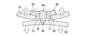
- the weld metal 40 fills the hollow portion 33 of the joining assisting member 30 and further form a swell Wa on the surface of the joining assisting member 30 (see FIG. 1B). If no bulge is formed, that is, as shown in FIG. 9A, when the hollow portion 33 remains in the appearance after welding, the joining strength is insufficient especially against external stress in the plate thickness direction (three-dimensional direction). (See FIG. 9B). Therefore, by forming the extra heap Wa, as shown in FIG. 10, deformation of the joining auxiliary member 30 is suppressed against external stress in the plate thickness direction (three-dimensional direction), and high joining strength is obtained. To be
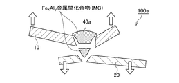
- the upper plate 10 made of aluminum and the lower plate 20 made of steel are simply stacked, and the welding wire made of steel or nickel alloy is placed from the upper plate side.
- the weld metal 40a formed is an alloy of aluminum and steel or an alloy of aluminum, steel and nickel. This alloy exhibits an intermetallic compound (IMC), which is a brittle property due to its high aluminum content.
- IMC intermetallic compound
- the weld metal 40a becomes an intermetallic compound in its entirety. It is also weak and not practical as a welded joint.
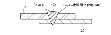
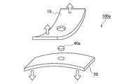
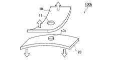
- a method in which a hole 11 having an appropriate size is opened in the upper plate 10 and a welding material of steel or nickel alloy is melted so as to fill the hole 11 can be considered.
- the welding metal 40b formed of the steel and the welding material, which is the lower plate 20 formed in the initial stage of welding does not melt aluminum, an intermetallic compound is not generated, and high strength and toughness are obtained. And is firmly connected to the lower plate 20.
- the weld metal 40b formed inside the hole 11 formed in the upper plate 10 has a very low aluminum melting rate, the generation of intermetallic compounds is significantly suppressed, and the center part has a soundness.
- the two-step-shaped joining auxiliary member 30 having the press-fitting protrusion 39 of the present embodiment is used so as to withstand the tensile stress in the shearing direction and the stress in the vertical peeling direction.
- the upper plate 10 is perforated, and the joining assisting member 30 is press-fitted into the hole 11 provided in the upper plate 10 and then fixed, and then the lower plate 20 to be joined.
- the weld metal 40 is formed by arc welding so as to fill the inside of the upper plate 10 and the joining auxiliary member 30.
- the joining assisting member 30, the weld metal 40, and the lower plate 20 are welded and joined together by a strong metal bond in cross section.
- the largest role of the flange portion 32 of the joining auxiliary member 30 which is wider than the hole 11 provided in the upper plate 10 is resistance to vertical peeling stress.
- FIG. 18A by applying the joining auxiliary member 30 having an appropriate size, it is possible to prevent the phenomenon that the interface between the upper plate 10 and the weld metal 40 peels off and comes off.
- the weld metal 40 sufficiently plastically deforms and then breaks. It is obvious that the joining assisting member 30 does not adversely affect the initial stress even with respect to the tensile stress in the shearing direction.
- the flange portion 32 of the joining auxiliary member 30 to increase the strength against external stress as the area is large and the thickness P H2 is larger thickness direction (three dimensional directions), desirable.
- the size of the joining assisting member 30 is determined according to the required design.
- the joining auxiliary member 30 has a protective wall action for avoiding melting of the Al alloy and the Mg alloy. This function is mainly performed by the shaft portion 31 of the joining auxiliary member 30.
- the most easily melted portion of the joint portion of the Al alloy or the Mg alloy is the inner surface of the hole 11 or the surface around the inner surface.
- the heat of arc welding is prevented from being directly transferred to the Al alloy or the Mg alloy, and is prevented from being mixed with steel to form an intermetallic compound (IMC). If the penetration range of the arc welding is limited to the joining auxiliary member 30 and the lower plate 20, the dilution of Al or Mg into the weld metal 40 becomes zero, and IMC is completely prevented. Therefore, as shown in FIG. 19A, the shaft portion 31 acts as a resistance action against external stress in the plate width direction (two-dimensional direction).
- the occurrence of IMC does not have to be zero, and some IMC formation is allowed.
- the weld metal 40 has ductility and an appropriate strength, the weld metal 40 is external in the plate width direction (two-dimensional direction). This is because the effect of the IMC layer formed around the weld metal 40 is small because it acts as a resistance action against stress.
- the IMC is brittle, even if tensile stress acts on the structure, the joint has a mechanism in which compressive stress and tensile stress are simultaneously applied, and the IMC has sufficient strength against compressive force. Therefore, the formation of the IMC layer does not lead to fracture propagation. Therefore, the shaft portion 31 of the joining assisting member 30 does not necessarily have to have the same thickness as the upper plate 10.
- the joining auxiliary member 30 plays a role of minimizing the gap (gap) generated in the superposed surfaces when the upper plate 10 made of Al alloy or Mg alloy and the lower plate 20 made of steel are superposed ( See FIG. 20A).
- the weld metal 40 undergoes thermal contraction, and at that time, a force acts in a direction in which both the lower plate 20 and the joining auxiliary member 30 approach each other.
- the gap g is reduced after welding, and the joint design accuracy is increased.
- the joining auxiliary member 30 plays a role in each of the shaft portion 31 and the flange portion 32, but the sizes of the shaft portion 31 and the flange portion 32 are important.
- the width P D2 of the flange portion 32 needs to be larger than the diameter B D of the hole 11 provided in the upper plate 10.
- the shaft portion 31 has a simple cylindrical shape without the press-fitting protrusion portion 39 and the outer diameter P D0 of the shaft portion 31 is smaller than the hole diameter B D of the upper plate 10, the diameter difference is industrially increased. Occurs. That is, the smaller the outer diameter P D0 of the shaft portion 31 is than the hole 11 formed in the upper plate 10, the easier the insertion of the shaft portion 31 is. The probability of failing will increase.
- the outer diameter P D0 of the shaft portion 31 is small from the viewpoint of insertability, but the gap formed between the hole 11 provided in the upper plate 10 and the shaft portion 31 of the joining auxiliary member 30 is This causes the upper plate 10 and the lower plate 20 to be displaced from each other. That is, in this joined state, a force for restraining the upper plate 10 in the horizontal direction is not generated, and therefore, when the upper plate 10 receives a shearing stress in the horizontal direction, the joining assisting member 30 and the hole 11 of the upper plate 10 can be relatively easily formed. There is a slippage due to the gap between them.
- the upper plate 10 After the upper plate 10 is displaced by the gap, it does not move easily, but even a slight amount of displacement easily causes a deterioration in design accuracy and is not allowed. Therefore, in the joined state, it is necessary that there is no gap between the joining auxiliary member 30 and the hole 11 of the upper plate 10.
- This state can be achieved by designing the outer diameter P D0 of the shaft portion 31 of the joining assisting member 30 to be larger than the diameter B D of the hole 11 of the upper plate 10 and inserting it under pressure.
- simply increasing the diameter not only makes it difficult to set the target position, but also significantly deteriorates the insertability, and even if the target position is set coaxially, a very high pressure is required.
- the press-fitting projection 39 on the outer peripheral surface of the shaft portion 31, it is possible to eliminate the gap between the shaft portion 31 and the hole 11 of the upper plate 10, and to improve the insertability. Both securing and securing can be achieved. That is, P D0 of the shaft portion 31 is made smaller than the hole diameter B D of the upper plate 10 and, on the other hand, the protrusion 39 bites into the wall surface of the hole 11 of the upper plate 10 to partially eliminate the gap. Since the protrusion 39 has a small thickness in the circumferential direction, the protrusion 39 is in a state close to a line contact with the hole 11 of the upper plate 10 and does not cause a significant increase in the pushing pressure.
- the joining assisting member 30 has a diameter P D1 of the largest circle C that is in contact with the outermost diameter portions of at least two protrusions 39, or the outermost diameter portion of one protrusion 39 and the outer peripheral surface of the shaft portion 31.
- the diameter P D1 of the contacting circle C is larger than the diameter B D of the hole 11 of the upper plate 10.
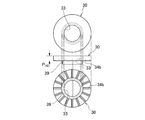
- the first is that the upper plate 10 and the lower plate 20, which are the joining targets, are hard to rotate relative to each other.
- the cross-sectional shape of the shaft portion 31 of the joining auxiliary member 30 is a true circle
- the joining auxiliary member 30 is joined by press fitting of the shaft portion 31, for example, when a strong horizontal rotational force F R is applied to the upper plate 10, the joining is performed.
- the upper plate 10 may rotate so as to rotate around the auxiliary member 30.
- the joining assisting member 30 is provided with the protrusion 39, and the protrusion 39 bites around the hole 11 of the upper plate 10 to easily prevent rotation. be able to.
- the upper plate 10 and the lower plate 20 can be joined together in any posture. If the press-fitting projection 39 is not provided and the maximum outer diameter P D0 of the shaft 31 is smaller than the diameter B D of the hole 11 of the upper plate 10 so that the shaft 31 can be easily taken in and out, for example, In the upward posture, the joining assisting member 30 falls and cannot be joined. However, as shown in FIG. 23, if the joining assisting member 30 is press-fitted into the hole 11 of the upper plate 10, the joining assisting member 30 does not easily drop, so that joining work is possible.
- the joining assisting members 30 are collectively press-fitted into the upper plate 10 of aluminum or magnesium alloy in a factory different from the joining.
- the joining step since the joining auxiliary member 30 does not easily come off from the upper plate 10, the joining step may be carried out after being transported to the joining factory, and the degree of freedom of the manufacturing step can be increased.
- the method for press-fitting the joining auxiliary member 30 may be any means, but it may be pushed in by a person's hand, hit with a hammer or the like, or a press machine using power such as hydraulic pressure, water pressure, air pressure, gas pressure, or electric drive may be used. There are practical means such as using the power of an industrial robot arm. Further, the joining auxiliary member 30 can be press-fitted by turning it into the hole 11. When such a means is used, as shown in FIG. 24, a screwdriver for screwing fits on the upper surface of the shaft portion 31. Providing the notch 38 makes it easier to turn the joining auxiliary member 30 into the upper plate 10.
- the pushing pressure is strong, not only the shaft portion 31 but also a part of the flange portion 32 may be pushed into the base material of the upper plate 10, but there is no problem. Rather, if the outer diameter of the flange portion 32 is non-circular (see FIGS. 7A to 7D), a part of the flange portion 32 is pushed into the base material of the upper plate 10 so that the upper plate 10 is attached to the lower plate 20. On the other hand, when a rotational force in the horizontal direction is applied, it is desirable to prevent the phenomenon that the caulking effect deviates with a comparatively weak force to rotate.
- the joining auxiliary member 30 is made of steel and has a stepped outer shape having the shaft portion 31 and the flange portion 32, and at least one press-fitting protrusion portion is provided on the outer peripheral surface of the shaft portion 31. 39 is provided, a hollow portion 33 that penetrates the shaft portion 31 and the flange portion 32 is formed, the width P D2 of the flange portion 32 is larger than the hole 11 of the upper plate 10, and the maximum width of at least two protruding portions 39. largest circle C of diameter P D1 in contact with the outer diameter, or the diameter of one hole 11 of the outermost diameter portion and the circle C diameter P D1 upper plate 10 in contact with the outer peripheral surface of the shaft portion 31 of the protrusion 39 B Those larger than D are used. This enables joining of an aluminum alloy or a magnesium alloy, which is generally impossible to weld, to a steel sheet.
- the material of the joining assisting member 30 made of steel is not particularly limited as long as it is pure iron or an iron alloy, and examples thereof include mild steel, carbon steel, stainless steel and the like.
- a surface treatment for forming a film such as an electrically base element, a processed product, an insulating substance, or a passivation on the joining auxiliary member 30 in order to prevent rust of itself and electrolytic corrosion generated between the joining auxiliary member 30 and the aluminum plate.
- Examples thereof include zinc plating, chrome plating, nickel plating, aluminum plating, tin (tin) plating, resin coating, and ceramic coating.
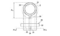
- various dimensions of the joining auxiliary member 30 are set as follows in relation to the upper plate 10 as shown in FIG. 25.
- the shaft height P H1 is designed to be 10% or more and 100% or less of the plate thickness B H of the upper plate 10.
- the shaft portion 31 of the joining assisting member 30 has an effect of preventing melting during the welding process of the Al and Mg upper plate 10 described above. It is preferable that the shaft height P H1 is larger because the heat transfer of the arc heat to the upper plate 10 is prevented. However, if the shaft height P H1 becomes larger than the plate thickness B H of the upper plate 10, a gap is created between the upper plate 10 and the lower plate 20, which is not desirable. Therefore, the upper limit of the shaft height P H1 is 100% with respect to the plate thickness B H. On the other hand, if it is less than 10%, the molten pool of steel comes into contact with aluminum or magnesium, and these are mixed to make the weld metal 40 extremely brittle. Accordingly, the lower limit of the shaft portion height P H1 is 10%.
- the diameter P D1 of the largest circle C that is in contact with the outermost diameter portion of the plurality of protrusions 39 provided on the shaft portion 31 is designed to be 105% or more and 125% or less of the diameter B D of the hole 11 of the upper plate 10.
- the protrusion 39 provided on the shaft portion 31 of the joining assisting member 30 has a function of restraining the caulking by press fitting into the upper plate 10. In order to exert the effect, the diameter P D1 of the maximum circle C must be larger than the hole diameter B D of the upper plate 10.
- the diameter P D1 of the maximum circle C is at least 5% or more larger than the hole diameter B D , appropriate pressure cannot be applied near the upper plate hole. Therefore, the diameter P D1 of the largest circle C is at least 105% or more of the hole diameter B D.
- the larger the diameter P D1 of the largest circle C that is in contact with the outermost diameter portion of the plurality of protrusions 39 the stronger the caulking force, but the greater the force required for press fitting, which impairs the convenience and further It may not be able to withstand the pressure around the upper plate hole and may cause cracks.
- the upper limit of the diameter P D1 of the maximum circle C is determined, and is specifically 125%.
- the diameter P D1 of the circle C contacting the outermost diameter portion of one protrusion 39 and the outer peripheral surface of the shaft 31 is the upper plate. It is designed to be 105% or more and 125% or less with respect to the diameter BD of the ten holes 11.
- the outer diameter P D0 of the shaft portion 31 is designed to be 80% or more and 104% or less with respect to the diameter B D of the hole 11 of the upper plate 10.
- the caulking restraint action on the upper plate 10 by the shaft portion 31 of the joining assisting member 30 is achieved by the protrusion portion 39. If the outer diameter P D0 of the shaft portion 31 is smaller than the hole diameter B D of the upper plate 10, it does not become a resistance factor for insertion and is desirable. However, if the outer diameter P D0 of the shaft portion 31 is excessively small, when the external stress acts on the dissimilar material welded joint 1 after joining, the shaft portion of the joining assisting member 30 is relatively weak in the plate surface direction.
- the outer diameter P D0 of the shaft portion 31 is less than 100% and closer to 100% of the diameter B D of the hole 11 of the upper plate 10.
- the upper limit of the outer diameter P D0 of the shaft portion 31 is allowed to be 104%, which is larger than the hole diameter B D of the upper plate 10.
- the width P D2 of the flange portion 32 is designed to be 105% or more of the diameter B D of the hole 11 of the upper plate 10.
- the flange portion 32 of the joining auxiliary member 30 has a main role as a resistance force against external stress in the plate thickness direction, in other words, when peeling stress acts.
- the shaft portion 31 also has a resistance to the peeling stress to some extent due to the effect of restraining the upper plate 10 by crimping, but the flange portion 32 has a large role.
- the joining assisting member 30 has a larger width P D2 of the flange portion 32 and has a larger thickness, because the joining assisting member 30 has higher strength against external stress in the plate thickness direction (three-dimensional direction).
- the width P D2 of the flange portion 32 is less than 105% of the diameter B DX of the hole 11, the size of the hole 11 of the upper plate 10 is large when the joining assisting member 30 is elastically plastically deformed by external stress in the plate thickness direction. It is easy for the apparent size to be less than the above, and the upper plate 10 is likely to come off. That is, the joining auxiliary member 30 does not exhibit high resistance. Therefore, the width P D2 of the flange portion 32 has a lower limit of 105% of the diameter B D of the hole 11. More preferably, the width P D2 of the flange portion 32 has a lower limit of 120% of the diameter B D of the hole 11. On the other hand, there is no need to set an upper limit from the viewpoint of the strength of the joint.
- the thickness P H2 of the flange portion 32 is designed to be 50% or more and 150% or less of the plate thickness B H of the upper plate 10. As described above, the flange portion 32 of the auxiliary bonding member 30 to increase the strength against external stress large external dimensions, and the thickness P H2 larger the thickness direction (three dimensional directions), desirable. The thickness P H2 of the flange portion 32 exhibits a high resistance by increasing in accordance with the thickness B H of the upper 10 of the joint.
- the flange portion 32 of the joining assisting member 30 When the thickness P H2 of the flange portion 32 is less than 50% of the plate thickness B H of the upper plate 10, the flange portion 32 of the joining assisting member 30 easily undergoes elastic-plastic deformation against external stress in the plate thickness direction, If the apparent size is equal to or smaller than the size of the hole 11 of the upper plate 10, it becomes easy to pull out. That is, the joining auxiliary member 30 does not exhibit high resistance. Therefore, the lower limit of the thickness P H2 of the flange portion 32 is 50% of the plate thickness B H of the upper plate 10.
- the thickness P H2 of the flange portion 32 exceeds 150% of the plate thickness B H of the upper plate 10, there is no problem in terms of joint strength, but the shape is excessively overhanging and the appearance is only poor. It also becomes heavier. Therefore, the thickness P H2 of the flange portion 32 needs to be 150% or less of the plate thickness B H of the upper plate 10.
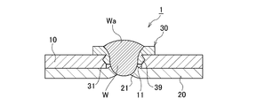
- the diameter W D of the extra wa is determined by the hollow portion 33 of the joining auxiliary member 30. Is set to 105% or more of the diameter P S of As described above, the joining assisting member 30 has a role of exerting a resistance force against external stress in the plate thickness direction (three-dimensional direction), but does not exert a high resistance force unless the hollow portion 33 is completely filled. If the hollow portion 33 is not completely filled and the inner surface of the hollow portion 33 remains, the joint area between the joining assisting member 30 and the weld metal 40 may be insufficient, and the hollow portion 33 may easily come off.
- the joining assist member 30 and the weld metal 40 be completely filled and the extra wa is formed.
- the diameter W D thereof exceeds the diameter P S of the hollow portion 33 of the joining auxiliary member 30. If the diameter W D of the extra fill Wa is 105% or more of the diameter P S of the hollow portion 33 of the joining assisting member 30, it means that the extra fill has been formed, so this is the lower limit.
- the plate thicknesses of the upper plate 10 and the lower plate 20 are not necessarily limited, the plate thickness of the upper plate 10 is 5.0 mm or less in consideration of the construction efficiency and the shape as lap welding. Is desirable. On the other hand, considering the heat input of arc welding, if the plate thickness is too thin, it will melt down during welding and welding will be difficult. Therefore, it is desirable that both the upper plate 10 and the lower plate 20 be 0.5 mm or more. .
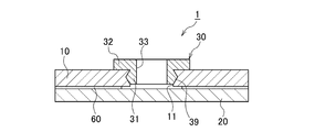
- the adhesive 60 may be annularly applied around the welded portion at the joint surface between the upper plate 10 and the lower plate 20.
- the adhesive 60 may be annularly applied around the welded portion at the joint surface between the upper plate 10 and the lower plate 20.
- This also includes the case of applying it to the entire joint surface except for the above. By this, the electrolytic corrosion rate of the upper plate 10, the lower plate 20, and the weld metal 40 can be reduced.
- the adhesive 60 may be applied between the periphery of the hole 11 of the upper plate 10 and the lower surface of the joining auxiliary member 30. Thereby, the electrolytic corrosion rate of the upper plate 10, the joining auxiliary member 30, and the weld metal 40 can be reduced.
- the adhesive 60 may be applied to the boundary between the joining assisting member 30 and the surface of the upper plate 10. As a result, the effect of reducing the electrolytic corrosion rate can be obtained.
- the coating can be performed only before the welding step, but in the fourth modification shown in FIGS. 29A and 29B, the coating can be performed before the welding step or after the welding step. Is.
- the contact surface of the joining assisting member 30 with the upper plate 10 does not necessarily have to be a flat surface, as shown in FIG. 30A. That is, the contact surface of the joining assisting member 30 with the upper plate 10 may be provided with slits 34a and 34b as necessary, as shown in FIGS. 30B and 30C.
- a circumferential slit 34a, a lattice slit 34b, or a radial slit (not shown) is provided on the contact surface side with the upper plate 10, the adhesive 60 is applied to the gap between the slits 34a and 34b. Since it enters and does not escape, stable adhesion is achieved and the sealing effect is also ensured. Defining the thickness P H2 of the flange portion 32 of the auxiliary bonding member 30 in the case of such a non-planar surface is the largest part of the height.
- the surface of the hollow portion 33 provided in the joining assisting member 30 may be a cylindrical surface having a uniform diameter, but a screw groove 33a may be formed as shown in FIG.
- a male screw is not used, but the screw groove 33a increases the contact surface area with the molten pool during arc welding, so that the weld metal 40 and the joining auxiliary member 30 are more firmly joined.
- the diameter P S of the hole 11 when it is not a cylindrical surface such as the screw groove 33a is defined as the widest facing distance.
- the bulging portion 21 may be provided on the lower plate 20.
- the plate thickness of the upper plate 10 made of Al alloy or Mg alloy is relatively thin, the lower plate 20 is not processed, the upper plate 10 is perforated, and the joining auxiliary member 30 is inserted into the hole 11 at the time of joining. Good welding is possible by itself.
- the plate thickness of the upper plate 10 is large, it takes time to fill the hollow portion 33 of the joining auxiliary member 30 in the welding process, resulting in poor efficiency.
- the heat input during welding becomes excessive, and the steel plate of the lower plate 20 is likely to melt down before the completion of filling. For this reason, if the bulging portion 21 is provided in the lower plate 20 by drawing, the volume of the hole 11 becomes small, so that filling can be performed while preventing burn-through defects.
- the bulged portion 21 of the lower plate 20 serves as a mark for aligning the upper plate 10 and the lower plate 20, and the bulged portion 21 of the lower plate 20 and the hole 11 of the upper plate 10. Can be easily aligned, which improves the efficiency of overlaying work.
- the peripheral portion of the portion of the lower plate 20 where the bulged portion 21 is formed is restrained by the die 50. Then, as shown in FIG. 34B, pressure is applied to the portion where the bulging portion 21 is formed, and the punch 51 is pushed in to form the bulging portion 21.
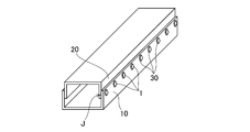
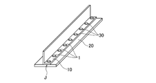
- the welding method of the present embodiment can be said to be spot welding with a small joint area. Therefore, when joining overlapping portions J of practical members having a certain joint area to each other, the present welding method is shown in FIGS. 35A to 35C. As shown, multiple implementations may be performed. As a result, strong joining is performed at the overlapping portion J.
- the present embodiment can be used for an open cross-section structure as shown in FIGS. 35B and 35C, but can be particularly preferably used for a closed cross-section structure as shown in FIG. 35A.
- the arc welding method for joining dissimilar materials of the present embodiment has a step of forming a circular hole 11 in the upper plate 10 and a stepped outer shape having a shaft portion 31 and a flange portion 32. At least one press-fitting projection 39 is provided on the outer peripheral surface of the shaft portion 31, a hollow portion 33 penetrating the shaft portion 31 and the flange portion 32 is formed, and the width P D2 of the flange portion 32 is equal to that of the upper plate 10.
- the diameter P D1 of the largest circle C that is larger than the diameter BD of the hole 11 and is in contact with the outermost diameter portions of at least two protrusions 39, or the outermost diameter portion of one protrusion 39 and the shaft portion 31.
- B A non-gas arc welding method using the welding wire as a welding electrode.
- C A gas tungsten arc welding method using the welding wire as a non-electrolytic electrode filler.
- D A plasma arc welding method using the welding wire as a non-electrolytic electrode filler.
- E A coated arc welding method in which a coated arc welding rod from which a weld metal 40 of an iron alloy or a Ni alloy is obtained is used as a welding electrode.
- the upper plate 10 of the Al alloy or the Mg alloy and the lower plate 20 of the steel can be joined with a strong and reliable quality by using inexpensive arc welding equipment, and an open cross-section structure or a closed cross-section structure can be obtained.
- the bulging portion 21 is formed on the lower plate 20 by drawing, and the bulging portion 21 of the lower plate 20 is arranged in the hole 11 of the upper plate 10 in the superposing process.
- a step of applying an adhesive agent 60 around the entire circumference of the hole 11 on at least one superposing surface of the upper plate 10 and the lower plate 20 is further provided.
- the adhesive acts as a sealing material in addition to improving the joint strength, and can reduce the electrolytic corrosion rate of the upper plate 10, the lower plate 20 and the weld metal 40.
- the adhesive 60 is applied to at least one of the facing surfaces between the joining auxiliary member 30 and the upper plate 10 facing the joining auxiliary member. Thereby, the electrolytic corrosion rate of the upper plate 10, the joining auxiliary member 30, and the weld metal 40 can be reduced.
- the adhesive 60 is applied to the boundary between the joining auxiliary member 30 and the surface of the upper plate 10. Thereby, the bonding strength between the upper plate 10 and the bonding auxiliary member 30 can be improved.
- the height P H1 of the shaft portion 31 of the joining assisting member 30 is 10% or more and 100% or less of the plate thickness B H of the upper plate 10, it is possible to suppress melting of the upper plate 10 during the welding process and perform welding. It is possible to suppress the embrittlement of the metal and prevent the gap between the upper plate 10 and the lower plate 20.
- the diameter P D1 of the largest circle C in contact with the outermost diameter of the at least two projections 39, or, a circle C of diameter P D1 in contact with the outermost diameter portion and the outer peripheral surface of the shaft portion 31 of the protrusion 39 Is 105% or more and 125% or less with respect to the diameter BD of the hole 11 of the upper plate 10, so that the joining assisting member 30 can be caulked and restrained in the hole 11 of the upper plate 10 with an appropriate caulking force.
- the maximum outer diameter P D0 of the shaft portion 31 of the joining assisting member 30 is 80% or more and 104% or less with respect to the diameter B D of the hole 11 of the upper plate 10, it is It is possible to suppress the displacement of the plate 10 and ensure insertability.
- the joining auxiliary member 30 since the width P D2 of the flange portion 32 of the joining auxiliary member 30 is 105% or more with respect to the diameter BD of the hole 11 of the upper plate 10, the joining auxiliary member 30 has a resistance to external stress in the plate thickness direction. Can act as a force.
- the joining auxiliary member 30 since the thickness P H2 of the flange portion 32 of the joining auxiliary member 30 is 50% or more and 150% or less of the plate thickness B H of the upper plate 10, the joining auxiliary member 30 considers appearance and weight increase. At the same time, it can function as a resistance force to external stress in the plate thickness direction.
- the extra wa is formed on the surface of the joining auxiliary member, and the diameter W D of the extra Wa is 105% or more with respect to the diameter P S of the hollow portion 33 of the joining auxiliary member 30. Therefore, the extra wa is capable of functioning as a resistance to external stress in the plate thickness direction.
- the joining assisting member 30 of the present embodiment is made of steel and has a stepped outer shape having a shaft portion 31 and a flange portion 32, and at least one press-fitting projection is provided on the outer peripheral surface of the shaft portion 31.
- the portion 39 is provided, the hollow portion 33 penetrating the shaft portion 31 and the flange portion 32 is formed, and the width P D2 of the flange portion 32 is each larger than the diameter B D of the hole 11 of the upper plate 10, and at least two largest circle C of diameter P D1 in contact with the outermost diameter of projections 39, or the diameter P D1 of the circle C in contact with the outer peripheral surface of the outermost diameter portion of the one protrusion 39 and the shaft portion 31 of the upper plate 10 It is larger than the diameter BD of the hole 11.
- the joining auxiliary member 30 is suitably used in the above-described arc welding method for joining dissimilar materials.
- the dissimilar material welded joint 1 of the present embodiment includes an upper plate 10 made of an aluminum alloy or a magnesium alloy, and a lower plate 20 made of steel that is arc-welded to the upper plate 10, and the upper plate 10 is a lower plate. It has a circular hole 11 facing the overlapping surface with the plate 20, and has a stepped outer shape having a shaft portion 31 and a flange portion 32 which are press-fitted into the hole 11 provided in the upper plate 10. At least one press-fitting projection 39 is provided on the outer peripheral surface of the shaft portion 31, a hollow portion 33 penetrating the shaft portion 31 and the flange portion 32 is formed, and the width P D2 of the flange portion 32 is the upper plate.
- the diameter P D1 of the largest circle C that is larger than the diameter B D of each of the holes 11 and is in contact with the outermost diameter portion of at least two protrusions 39, or the outermost diameter portion and the shaft portion of one protrusion 39.
- 31 diameter P D1 is the upper plate 10 of the circle C in contact with the outer peripheral surface of the Further comprising a diameter B auxiliary bonding member 30 made of steel is larger than D of the hole 11, the hollow portion 33 of the auxiliary bonding member 30 are iron alloys, or, together with is filled with weld metal 40 of Ni alloy, the weld metal 40 And the melted lower plate 20 and a part of the joining auxiliary member 30 form a melted portion W.
- the dissimilar material welded joint 1 including the upper plate 10 of the Al alloy or the Mg alloy and the lower plate 20 of the steel is joined with strong and reliable quality using the inexpensive arc welding equipment, and is opened. It can be applied to both a cross-section structure and a closed cross-section structure without limitation.
- the plate member with a joining assisting member of the present embodiment includes an upper plate (a plate member made of an aluminum alloy or a magnesium alloy) 10 made of an aluminum alloy or a magnesium alloy having a circular hole 11, a shaft portion 31 and a flange portion 32. At least one press-fitting projection 39 is provided on the outer peripheral surface of the shaft portion 31, and a hollow portion 33 penetrating the shaft portion 31 and the flange portion 32 is formed.
- the width P D2 of 32 is larger than the diameter B D of the hole 11 of the upper plate 10, and the diameter P D1 of the largest circle C that is in contact with the outermost diameter portion of at least two protrusions 39, or one protrusion 39.
- the joining assisting member 30 is a joining assisting member made of steel in which a diameter P D1 of a circle C that is in contact with the outermost diameter portion of the shaft 31 and the outer peripheral surface of the shaft portion 31 is larger than the diameter B D of the hole 11 of the upper plate 10, the joining assisting member 30 is , Pressure
- protrusion 39 is press-fitted into the hole 11 provided in the upper plate 10 is attached to the upper plate 19.
- the plate material with the joining auxiliary member can be arc-welded with the steel lower plate (steel plate material) 20 to form a dissimilar material welded joint with strong and highly reliable quality.
Abstract
アルミニウム合金又はマグネシウム合金と、鋼との異材を、安価なアーク溶接設備を用いて、強固かつ信頼性の高い品質で接合できる、異材接合用アーク溶接法を提供する。異材溶接継手(1)は、アルミニウム合金又はマグネシウム合金製の上板(10)と、上板(10)にアーク溶接された、鋼製の下板(20)と、鋼製の接合補助部材(30)と、を備える。上板(10)は、下板(20)との重ね合わせ面に臨む円形の穴(11)を有する。接合補助部材(30)は、軸部(31)とフランジ部(32)とを持った段付きの外形形状を有し、軸部(31)の外周面には少なくとも1つの圧入用突起部(39)が設けられ、軸部(31)及びフランジ部(32)を貫通する中空部(33)が形成される。接合補助部材(30)は、上板(10)の穴(11)に圧入され、中空部(33)は、鉄合金、又は、Ni合金の溶接金属(40)で充填される。
Description
本発明は、異材接合用アーク溶接法、接合補助部材、異材溶接継手、及び、接合補助部材付き板材に関する。
自動車を代表とする輸送機器には、(a)有限資源である石油燃料消費、(b)燃焼に伴って発生する地球温暖化ガスであるCO2、(c)走行コストといった各種の抑制を目的として、走行燃費の向上が常に求められている。その手段としては、電気駆動の利用など動力系技術の改善の他に、車体重量の軽量化も改善策の一つである。軽量化には現在の主要材料となっている鋼を、軽量素材であるアルミニウム合金、マグネシウム合金、炭素繊維などに置換する手段がある。しかし、全てをこれら軽量素材に置換するには、高コスト化や強度不足になる、といった課題があり、解決策として鋼と軽量素材を適材適所に組み合わせた、いわゆるマルチマテリアルと呼ばれる設計手法が注目を浴びている。
鋼と上記軽量素材を組み合わせるには、必然的にこれらを接合する箇所が出てくる。鋼同士やアルミニウム合金同士、マグネシウム合金同士では容易である溶接が、異材では極めて困難であることが知られている。この理由として、鋼とアルミニウムあるいはマグネシウムの溶融混合部には、極めて脆い性質である金属間化合物(IMC)が生成し、引張や衝撃といった外部応力で溶融混合部が容易に破壊してしまうことにある。このため、抵抗スポット溶接法やアーク溶接法といった溶接法が異材接合には採用できず、他の接合法を用いるのが一般的である。鋼と炭素繊維の接合も、後者が金属ではないことから溶接を用いることができない。
従来の異材接合技術の例としては、鋼素材と軽量素材の両方に貫通穴を設けてボルトとナットで上下から拘束する手段があげられる。また、他の例としては、かしめ部材を強力な圧力をかけて片側から挿入し、かしめ効果によって拘束する手段が知られている(例えば、特許文献1参照)。
さらに、他の例としては、アルミ合金素材に鋼製の接合部材をポンチとして押し込むことで穴あけと接合部材を仮拘束し、次に鋼素材と重ね合わせ、上下両方から銅電極にて挟み込んで、圧力と高電流を瞬間的に与えて鋼素材と接合部材を抵抗溶接する手段が提案されている(例えば、特許文献2参照)。
また、他の例としては、摩擦攪拌接合ツールを用いてアルミ合金と鋼の素材同士を直接接合する手段も開発されている(例えば、特許文献3参照)。
しかしながら、ボルトとナットによる接合法は、鋼素材と軽量素材が閉断面構造を構成するような場合(図35A参照)、ナットを入れることができず適用できない。また、適用可能な開断面構造の継手の場合(図35B、図35C参照)でも、ナットを回し入れるのに時間を要し能率が悪いという課題がある。
また、特許文献1に記載の接合法は、比較的容易な方法ではあるが、鋼の強度が高い場合には、かしめ部材を挿入できない問題があり、かつ、接合強度は摩擦力とかしめ部材の剛性に依存するので、高い接合強度が得られないという問題がある。また、かしめ部材の挿入に際しては表と裏の両側から治具で押さえ込む必要があるため、閉断面構造には適用できないという課題もある。
さらに、特許文献2に記載の接合法も、閉断面構造には適用できず、また、抵抗溶接法は設備が非常に高価であるという課題がある。
特許文献3に記載の接合法は、アルミ合金素材を低温領域で塑性流動させながら鋼素材面に圧力をかけることで、両素材が溶融し合うことがなく、金属間化合物の生成を防止しながら金属結合力が得られるとされ、鋼と炭素繊維も接合可能という研究成果もある。しかしながら、本接合法も閉断面構造には適用できず、また高い圧力を必要とするので機械的に大型となり、高価であるという問題がある。また、接合力としてもそれほど高くならない。
したがって、既存の異材接合技術は、(i)部材や開先形状が開断面構造に限定される、(ii)接合強度が低い、(iii)設備コストが高価である、といった一つ以上の問題を持っている。このため、種々の素材を組み合わせたマルチマテリアル設計を普及させるためには、(i’)開断面構造と閉断面構造の両方に適用できる、(ii’)接合強度が十分に高く、かつ信頼性も高い、(iii’)低コストである、という全ての要素を兼ね備えた、使いやすい新技術が求められている。
本発明は、前述した課題に鑑みてなされたものであり、その目的は、アルミニウム合金(以下「Al合金」とも言う)若しくはマグネシウム合金(以下、「Mg合金」とも言う)と鋼の異材を、既に世に普及している安価なアーク溶接設備を用いて、強固かつ信頼性の高い品質で接合でき、かつ開断面構造にも閉断面構造にも制限無く適用できる、異材接合用アーク溶接法、接合補助部材、異材溶接継手、及び、接合補助部材付き板材を提供することにある。
ここで、Al合金若しくはMg合金と鋼を溶融接合させようとすると、上述したように金属間化合物(IMC)の生成が避けられない。一方、鋼同士の溶接は最も高い接合強度と信頼性を示すことは、科学的にも実績的にも自明である。
そこで、本発明者らは、鋼同士の溶接を結合力として用い、さらに拘束力を利用して異材の接合を達成する手段を考案した。
そこで、本発明者らは、鋼同士の溶接を結合力として用い、さらに拘束力を利用して異材の接合を達成する手段を考案した。
したがって、本発明の上記目的は、異材接合用アーク溶接法に係る下記(1)の構成により達成される。
(1) アルミニウム合金若しくはマグネシウム合金製の第1の板と、鋼製の第2の板と、を接合する異材接合用アーク溶接法であって、
前記第1の板に円形の穴を空ける工程と、
軸部とフランジ部とを持った段付きの外形形状を有し、前記軸部の外周面には少なくとも1つの圧入用突起部が設けられ、前記軸部及び前記フランジ部を貫通する中空部が形成され、前記フランジ部の幅が前記第1の板の穴の直径より大きく、かつ、少なくとも2つの前記突起部の最外径部と接する最大円の直径、又は、1つの前記突起部の最外径部と前記軸部の外周面と接する円の直径が前記第1の板の穴の直径よりも大きい鋼製の接合補助部材を、前記第1の板の穴に圧入する工程と、
前記第1の板と前記第2の板を重ね合わせる工程と、
以下の(a)~(e)のいずれかの手法によって、前記接合補助部材の中空部を溶接金属で充填すると共に、前記第2の板及び前記接合補助部材を溶接する工程と、を備える異材接合用アーク溶接法。
(a)鉄合金、又は、Ni合金の前記溶接金属が得られる溶接ワイヤを溶極として用いるガスシールドアーク溶接法。
(b)前記溶接ワイヤを溶極として用いるノンガスアーク溶接法。
(c)前記溶接ワイヤを非溶極フィラーとして用いるガスタングステンアーク溶接法。
(d)前記溶接ワイヤを非溶極フィラーとして用いるプラズマアーク溶接法。
(e)鉄合金、又は、Ni合金の前記溶接金属が得られる被覆アーク溶接棒を溶極として用いる被覆アーク溶接法。
また、異材接合用アーク溶接法に係る本発明の好ましい実施形態は、以下の(2)~(11)に関する。
(2) 前記第2の板には、絞り加工により膨出部が形成されており、
前記重ね合わせ工程において、前記第2の板の膨出部が、前記第1の板の穴内に配置される、(1)に記載の異材接合用アーク溶接法。
(3) 前記重ね合わせ工程の前に、前記第1の板と前記第2の板の少なくとも一方の重ね合せ面には、前記穴の周囲に、全周に亘って接着剤を塗布する工程を、さらに備える、(1)又は(2)に記載の異材接合用アーク溶接法。
(4) 前記圧入工程において、前記接合補助部材と、該接合補助部材と対向する前記第1の板との間の少なくとも一方の対向面に、接着剤を塗布する、(1)~(3)のいずれかに記載の異材接合用アーク溶接法。
(5) 前記圧入工程の際、又は、前記充填溶接工程後に、前記接合補助部材と、前記第1の板の表面との境界部に接着剤を塗布する、(1)~(4)のいずれかに記載の異材接合用アーク溶接法。
(6) 前記接合補助部材の軸部の高さPH1は、前記第1の板の板厚BHの10%以上100%以下である、(1)~(5)のいずれかに記載の異材接合用アーク溶接法。
(7) 前記少なくとも2つの突起部の最外径部と接する最大円の直径PD1、又は、前記1つの突起部の最外径部と前記軸部の外周面と接する円の直径PD1は、前記第1の板の穴の直径BDに対し105%以上125%以下である、(1)~(6)のいずれかに記載の異材接合用アーク溶接法。
(8) 前記接合補助部材の軸部の外径PD0は、前記第1の板の穴の直径BDに対し80%以上104%以下である、(1)~(7)のいずれかに記載の異材接合用アーク溶接法。
(9) 前記接合補助部材のフランジ部の幅PD2は、前記第1の板の穴の直径BDに対し105%以上である、(1)~(8)のいずれかに記載の異材接合用アーク溶接法。
(10) 前記接合補助部材のフランジ部の厚さPH2は、前記第1の板の板厚BHの50%以上150%以下である、(1)~(9)のいずれかに記載の異材接合用アーク溶接法。
(11) 前記充填溶接工程において、前記接合補助部材の表面上に余盛りが形成され、かつ前記余盛りの直径WDが、前記接合補助部材の中空部の直径PSに対し、105%以上となる、(1)~(10)のいずれかに記載の異材接合用アーク溶接法。
また、本発明の上記目的は、接合補助部材に係る下記(12)の構成により達成される。
(12) (1)~(11)のいずれかに記載の異材接合用アーク溶接法に用いられ、
鋼製で、軸部とフランジ部とを持った段付きの外形形状を有し、前記軸部の外周面には少なくとも1つの圧入用突起部が設けられ、前記軸部及び前記フランジ部を貫通する中空部が形成され、前記軸部の最大外径及び前記フランジ部の幅が前記第1の板の穴の直径よりそれぞれ大きく、かつ、少なくとも2つの前記突起部の最外径部と接する最大円の直径、又は、1つの前記突起部の最外径部と前記軸部の外周面と接する円の直径が前記第1の板の穴の直径よりも大きい、接合補助部材。
(12) (1)~(11)のいずれかに記載の異材接合用アーク溶接法に用いられ、
鋼製で、軸部とフランジ部とを持った段付きの外形形状を有し、前記軸部の外周面には少なくとも1つの圧入用突起部が設けられ、前記軸部及び前記フランジ部を貫通する中空部が形成され、前記軸部の最大外径及び前記フランジ部の幅が前記第1の板の穴の直径よりそれぞれ大きく、かつ、少なくとも2つの前記突起部の最外径部と接する最大円の直径、又は、1つの前記突起部の最外径部と前記軸部の外周面と接する円の直径が前記第1の板の穴の直径よりも大きい、接合補助部材。
また、本発明の上記目的は、異材溶接継手に係る下記(13)の構成により達成される。
(13) アルミニウム合金若しくはマグネシウム合金製の第1の板と、該第1の板にアーク溶接された、鋼製の第2の板と、を備える異材溶接継手であって、
前記第1の板は、前記第2の板との重ね合わせ面に臨む円形の穴を有し、
軸部とフランジ部とを持った段付きの外形形状を有し、前記軸部の外周面には少なくとも1つの圧入用突起部が設けられ、前記軸部及び前記フランジ部を貫通する中空部が形成され、前記フランジ部の幅が前記第1の板の穴の直径より大きく、かつ、少なくとも2つの前記突起部の最外径部と接する最大円の直径、又は、1つの前記突起部の最外径部と前記軸部の外周面と接する最大円の直径が前記第1の板の穴の直径よりも大きい鋼製の接合補助部材をさらに備え、
前記接合補助部材の軸部は、前記圧入用突起部を介して前記第1の板に設けられた穴内に固定され、
前記接合補助部材の中空部は、鉄合金、又は、Ni合金の溶接金属で充填されると共に、前記溶接金属と、溶融された前記第2の板及び前記接合補助部材の一部とによって溶融部が形成される、異材溶接継手。
また、異材溶接継手に係る本発明の好ましい実施形態は、以下の(14)~(23)に関する。
(14) 前記第1の板の穴内には、前記第2の板に形成された膨出部が配置される、(13)に記載の異材溶接継手。
(15) 前記第1の板と前記第2の板の少なくとも一方の前記重ね合せ面には、前記穴の周囲に、全周に亘って設けられた接着剤を備える、(13)又は(14)に記載の異材溶接継手。
(16) 前記接合補助部材と、該接合補助部材と対向する前記第1の板との間の少なくとも一方の対向面に設けられた接着剤を備える、(13)~(15)のいずれかに記載の異材溶接継手。
(17) 前記接合補助部材と、前記第1の板の表面との境界部に設けられた接着剤を備える、(13)~(16)のいずれかに記載の異材溶接継手。
(18) 前記接合補助部材の軸部の高さPH1は、前記第1の板の板厚BHの10%以上100%以下である、(13)~(17)のいずれかに記載の異材溶接継手。
(19) 前記少なくとも2つの突起部の最外径部と接する最大円の直径PD1、又は、前記1つの突起部の最外径部と前記軸部の外周面と接する円の直径PD1は、前記第1の板の穴の直径BDに対し105%以上125%以下である、(13)~(18)のいずれかに記載の異材溶接継手。
(20) 前記接合補助部材の軸部の外径PD0は、前記第1の板の穴の直径BDXに対し80%以上104%以下である、(13)~(19)のいずれかに記載の異材溶接継手。
(21) 前記接合補助部材のフランジ部の幅PD2は、前記第1の板の穴の直径BDXに対し105%以上である、(13)~(20)のいずれかに記載の異材溶接継手。
(22) 前記接合補助部材のフランジ部の厚さPH2は、前記第1の板の板厚BHの50%以上150%以下である、(13)~(21)のいずれかに記載の異材溶接継手。
(23) 前記接合補助部材の表面上に余盛りが形成され、かつ前記余盛りの直径WDが、前記接合補助部材の中空部の直径PSに対し、105%以上となる、(13)~(22)のいずれかに記載の異材溶接継手。
また、本発明の上記目的は、接合補助部材付き板材に係る下記(24)の構成により達成される。
(24) 鋼製の板材とアーク溶接することで異材溶接継手を形成可能な接合補助部材付き板材であって、
円形の穴を有するアルミニウム合金若しくはマグネシウム合金製の板材と、
軸部と、フランジ部と、を持った段付きの外形形状を有し、前記軸部の外周面には少なくとも1つの圧入用突起部が設けられ、前記軸部及び前記フランジ部を貫通する中空部が形成され、前記フランジ部の幅が前記板材の穴の直径より大きく、かつ、少なくとも2つの前記突起部の最外径部と接する最大円の直径、又は、1つの前記突起部の最外径部と前記軸部の外周面と接する円の直径が前記第1の板の穴の直径よりも大きい鋼製の接合補助部材と、を備え、
前記接合補助部材は、前記圧入用突起部が前記板材に設けられた穴内に圧入されることで、前記板材に取り付けられている、接合補助部材付き板材。
本発明によれば、アルミニウム合金若しくはマグネシウム合金と、鋼との異材を、安価なアーク溶接設備を用いて、強固かつ信頼性の高い品質で接合でき、かつ開断面構造にも閉断面構造にも制限無く適用できる。
以下、本発明の一実施形態に係る異材接合用アーク溶接法、接合補助部材、異材溶接継手、及び、接合補助部材付き板材を図面に基づいて詳細に説明する。
本実施形態の異材接合用アーク溶接法は、互いに重ね合わせされる、アルミニウム合金若しくはマグネシウム合金製の上板10(第1の板)と、鋼製の下板20(第2の板)とを、鋼製の接合補助部材30を介して、後述するアーク溶接法によって接合することで、図1A及び図1Bに示すような異材溶接継手1を得るものである。
上板10には、板厚方向に貫通して、下板20の重ね合わせ面に臨む円形の穴11が設けられており、この穴11に接合補助部材30が圧力をかけて挿入される。
図2A及び図2Bに示すように、接合補助部材30は、上板10の穴11内に配置される軸部31と、上板10の上面に配置され、軸部31に対して外向きのフランジ部32と、を持った段付きの外形形状を有する。また、軸部31の外周面には、少なくとも1つ(本実施形態では、4つ)の圧入用突起部39が設けられている。接合補助部材30には、軸部31及びフランジ部32を貫通する円形の中空部33が形成されている。
また、後述するように、フランジ部32の幅PD2は、上板10の穴11の直径BDより大きく設定されている(図25A参照)。また、複数の突起部39の最外径部と接する最大円Cの直径PD1も、上板10の穴11の直径BDより大きく設定されている。
突起部39は、接合補助部材30の軸部31を上板10の穴11内にかしめ拘束力をもって固定するため、軸部31と上板10の穴11との間の隙間を無くすこと、及び軸部31の挿入性を考慮して羽根状に形成される。すなわち、軸部31の最大外径PD0は、上板10の穴11の直径BDより小さくし、一方、突起部39を上板10の穴11の壁面に食い込ませて、部分的に上記隙間を無くす。また、突起部39の形状は、挿入性を考慮して、軸部31の先端部からフランジ部側に向けて徐々に径方向幅が増加するほうが好ましい。さらに、突起部39の円周方向の厚みが薄いので、上板10の穴11に対して線接触に近い状態になり、さほどの押し込み圧力の上昇をもたらさない。
突起部39の形状は、図2A及び図2Bに示すような2等辺三角形でもよいが、図3A~図3Iに示すように、他の形状の三角形状、長方形、部分円形、台形などが典型的で、その形状に制限はない。また、突起部39は、フランジ部32の下面とも接続されていることで、突起部39の強度を向上できる。さらに、突起部39は、図2Aに示すように、軸部31の軸方向に平行でもよいし、図4Aに示すように軸方向に対して傾きを持たせてもよい。この場合、接合補助部材30を回転させながら圧入するのに好適である。また、図4Bに示すように、突起部39は、基部から先端部に向けて円周方向幅が狭くなるような山形状であってもよい。
また、突起部39の数は、図2に示すような4枚に限定されず、少なくとも1枚あればよく、上限は特に設ける必要はない。すなわち、図5A~図5Eに示すように、1枚、2枚、3枚、6枚、8枚の突起部39を有するものであってもよい。ただし、突起部39の枚数が増えると、上板10の穴11との接触面積が増えて挿入に必要な圧力が上がるので、必要以上に突起部39の数を増やすべきではない。突起部39の数は、8枚以下とするのが望ましい。
なお、図5Aに示すように、突起部39が1つの場合には、1つの突起部39の最外径部と軸部31の外周面と接する円Cの直径PD1も、上板10の穴11の直径BDより大きく設定される。
なお、図5Aに示すように、突起部39が1つの場合には、1つの突起部39の最外径部と軸部31の外周面と接する円Cの直径PD1も、上板10の穴11の直径BDより大きく設定される。
また、接合補助部材30は、上述した突起部39の数、及び形状を任意に組み合わせて設計することができる。例えば、図6Aに示すような、3つの直角三角形状の突起部39を有する接合補助部材30を構成してもよい。図6Bは、図6Aの接合補助部材30を用いた場合の異材溶接継手1の図1Bに対応する断面図である。また、突起部39における機能は、上述した接合補助部材30のいずれであっても実質的に変わらないため、任意の接合補助部材30を用いて以降の説明を行っている。
さらに、接合補助部材30のフランジ部32の外形形状は、図2A及び図2Bに示すような円形に限定されず、溶接後に上板10に空けられた穴11を塞いでいれば、任意の形状とすることができる。例えば、図7A~図7Dに示す四角形以上の多角形でもよい。また、図7Bに示すように、多角形の角部を丸くしてもよい。
なお、これらの接合補助部材30では、後述するフランジ部32の幅PD2は、最も短い対向面間距離で規定される。また、フランジ部32が円形の場合には、外径をフランジ部32の幅PD2とする。
なお、これらの接合補助部材30では、後述するフランジ部32の幅PD2は、最も短い対向面間距離で規定される。また、フランジ部32が円形の場合には、外径をフランジ部32の幅PD2とする。
このように、接合補助部材30が上板10に圧入されることで、軸部31は、上板10の穴11内に固定される。複数の突起部39が円周方向に等間隔に設けられる場合には、軸部31及び中空部33は上板10の穴11と同軸上に位置している。一方、1つの突起部39が軸部31に設けられる場合は、軸部31及び中空部33は上板10の穴11にオフセットして位置している。
また、接合補助部材30の中空部33には、アーク溶接によってフィラー材(溶接材料)が溶融した、鉄合金、又は、Ni合金の溶接金属40が充填されると共に、溶接金属40と、溶融された下板20及び接合補助部材30の一部とによって溶融部Wが形成される。したがって、溶融部Wは、上板10の穴11内にも配置されて、接合補助部材30と下板20とを溶接しており、これによって、上板10と下板20とが接合される。
以下、異材溶接継手1を構成する異材接合用アーク溶接法について、図8A~図8Dを参照して説明する。
まず、図8Aに示すように、上板10に穴11を空ける穴開け作業を行う(ステップS1)。次に、図8Bに示すように、接合補助部材30を、上板10の上面から上板10の穴11に圧入する(ステップS2)。具体的には、軸部31に形成された圧入用突起部39が上板10の穴11に食い込んで圧入される。さらに、図8Cに示すように、上板10と下板20を重ね合わせる重ね合わせ作業を行う(ステップS3)。そして、図8Dに示すように、以下に詳述する(a)溶極式ガスシールドアーク溶接法、(b)ノンガスアーク溶接法、(c)ガスタングステンアーク溶接法、(d)プラズマアーク溶接法、(e)被覆アーク溶接法のいずれかのアーク溶接作業を行うことで、上板10と下板20とを接合する(ステップS4)。なお、図8Dは、(a)溶極式ガスシールドアーク溶接法を用いてアーク溶接作業が行われた場合を示している。
まず、図8Aに示すように、上板10に穴11を空ける穴開け作業を行う(ステップS1)。次に、図8Bに示すように、接合補助部材30を、上板10の上面から上板10の穴11に圧入する(ステップS2)。具体的には、軸部31に形成された圧入用突起部39が上板10の穴11に食い込んで圧入される。さらに、図8Cに示すように、上板10と下板20を重ね合わせる重ね合わせ作業を行う(ステップS3)。そして、図8Dに示すように、以下に詳述する(a)溶極式ガスシールドアーク溶接法、(b)ノンガスアーク溶接法、(c)ガスタングステンアーク溶接法、(d)プラズマアーク溶接法、(e)被覆アーク溶接法のいずれかのアーク溶接作業を行うことで、上板10と下板20とを接合する(ステップS4)。なお、図8Dは、(a)溶極式ガスシールドアーク溶接法を用いてアーク溶接作業が行われた場合を示している。
ステップS1の穴開け作業の具体的な手法としては、a)ポンチを用いた打抜き、b)金型を用いたプレス型抜き、c)レーザ、プラズマ、ウォータージェット法などによる切断があげられる。
また、ステップS4のアーク溶接作業は、上板10の穴11内の溶接金属40を介して接合補助部材30と下板20を接合し、かつ接合補助部材30に設けられた中空部33を充填するために必要とされる。したがって、アーク溶接には充填材となるフィラー材(溶接材料)の挿入が不可欠となる。具体的に、以下の4つのアーク溶接法により、フィラー材が溶融して溶接金属40が形成される。
(a) 溶極式ガスシールドアーク溶接法は、一般的にMAG(Metal Active Gas)やMIG(Metal Inert Gas)と呼ばれる溶接法であり、ソリッドワイヤ若しくはフラックス入りワイヤをフィラー兼アーク発生溶極として用い、CO2,O2,Ar,Heといったシールドガスで溶接部を大気から遮断して健全な溶接部を形成する手法である。
(b)ノンガスアーク溶接法は、セルフシールドアーク溶接法とも呼ばれ、特殊なフラックス入りワイヤをフィラー兼アーク発生溶極として用い、一方、シールドガスを不要として、健全な溶接部を形成する手段である。
(c)ガスタングステンアーク溶接法は、ガスシールドアーク溶接法の一種であるが非溶極式であり、一般的にTIG(Tungsten Inert Gas)とも呼ばれる。シールドガスは、Ar又はHeの不活性ガスが用いられる。タングステン電極と母材との間にはアークが発生し、フィラーワイヤはアークに横から送給される。
一般的に、フィラーワイヤは通電されないが、通電させて溶融速度を高めるホットワイヤ方式TIGもある。この場合、フィラーワイヤにはアークは発生しない。
一般的に、フィラーワイヤは通電されないが、通電させて溶融速度を高めるホットワイヤ方式TIGもある。この場合、フィラーワイヤにはアークは発生しない。
(d)プラズマアーク溶接法はTIGと原理は同じであるが、ガスの2重系統化と高速化によってアークを緊縮させ、アーク力を高めた溶接法である。
(e)被覆アーク溶接法は、金属の芯線にフラックスを塗布した被覆アーク溶接棒をフィラーとして用いるアーク溶接法であり、シールドガスは不要である。
フィラー材(溶接材料)の材質については、溶接金属40がFe合金となるものであれば、一般的に用いられる溶接用ワイヤ又は溶接棒が適用可能である。なお、Ni合金でも鉄との溶接には不具合を生じないので適用可能である。
具体的には、JISとして(a)Z3312,Z3313,Z3317,Z3318,Z3321,Z3323,Z3334、(b)Z3313、(c)Z3316,Z3321,Z3334,(d)Z3211,Z3221,Z3223,Z3224、AWS(American Welding Society)として、(a)A5.9,A5.14,A5.18,A5.20,A5.22,A5.28,A5.29,A5.34、(b)A5.20、(c)A5.9,A5.14,A5.18,A5.28,(d)A5.1,A5.4,A5.5,A5.11といった規格材が流通している。
具体的には、JISとして(a)Z3312,Z3313,Z3317,Z3318,Z3321,Z3323,Z3334、(b)Z3313、(c)Z3316,Z3321,Z3334,(d)Z3211,Z3221,Z3223,Z3224、AWS(American Welding Society)として、(a)A5.9,A5.14,A5.18,A5.20,A5.22,A5.28,A5.29,A5.34、(b)A5.20、(c)A5.9,A5.14,A5.18,A5.28,(d)A5.1,A5.4,A5.5,A5.11といった規格材が流通している。
これらのアーク溶接法を用いて接合補助部材30の中空部33をフィラー材で充填するが、一般的にフィラーワイヤ若しくは溶接棒の狙い位置は移動させる必要がなく、適切な送給時間を経てアークを切って溶接終了させれば良い。ただし、中空部33の面積が大きい場合は、フィラーワイヤ若しくは溶接棒の狙い位置を中空部33内で円を描くように移動させても良い。
溶接金属40は接合補助部材30の中空部33を充填し、さらに接合補助部材30の表面に余盛りWaを形成するのが望ましい(図1B参照)。余盛りを形成しない、すなわち、図9Aに示すように、中空部33が溶接後に外観上残る状態だと、特に、板厚方向(3次元方向)の外部応力に対しては、接合強度が不足となる可能性がある(図9B参照)。このため、余盛りWaを形成することで、図10に示すように、板厚方向(3次元方向)の外部応力に対しては、接合補助部材30の変形が抑えられ、高い接合強度が得られる。
一方、余盛り側と反対側の溶込みについては、図11Aに示すように、下板20を適度に溶融していることが必要である。なお、図11Bに示すように、下板20の板厚を超えて溶接金属40が形成される、いわゆる裏波が出る状態にまで溶けても問題はない。
ただし、下板20が溶けずに、溶接金属40が乗っかっているだけであると、高い強度は得られない。また、溶接金属40が深く溶け込みすぎて、溶接金属40と下板20が溶け落ちてしまわないように溶接する必要がある。
以上の作業によって、Al合金やMg合金製の上板10と鋼製の下板20は高い強度で接合される。
ただし、下板20が溶けずに、溶接金属40が乗っかっているだけであると、高い強度は得られない。また、溶接金属40が深く溶け込みすぎて、溶接金属40と下板20が溶け落ちてしまわないように溶接する必要がある。
以上の作業によって、Al合金やMg合金製の上板10と鋼製の下板20は高い強度で接合される。
以下、上記アーク溶接法において使用される鋼製の接合補助部材30の役割について説明する。
まず、接合補助部材を使用せず、図12A及び図12Bに示すように、単純にアルミ製の上板10と鋼製の下板20とを重ね、上板側から鋼若しくはニッケル合金製溶接ワイヤを用いたアーク溶接を定点で一定時間保持したアークスポット溶接を行った場合、形成される溶接金属40aはアルミと鋼、若しくはアルミと鋼とニッケルの合金となる。この合金は、アルミ含有量が多いので脆性的特性である金属間化合物(IMC)を呈している。このような異材溶接継手100aは、一見接合されている様に見えても、横方向に引張応力がかかる(せん断引張)と、図13A及び図13Bに示すように、溶接金属40aが容易に破壊して、外れてしまう。また、縦方向に引張応力がかかる(剥離引張)場合でも、図14A及び図14Bに示すように、溶接金属40aが破断するか、若しくは溶接金属40aと上板10の境界部あるいは溶接金属40aと下板20の境界部が破断し、上板10が抜けるようにして接合が外れてしまう。
このように単にアルミ製の上板10と鋼製の下板20を重ねて、貫通溶接しようとしても、溶接金属40aは全部分が金属間化合物になってしまうので、せん断引張にも剥離引張にも弱く、溶接継手としては実用にならない。
このように単にアルミ製の上板10と鋼製の下板20を重ねて、貫通溶接しようとしても、溶接金属40aは全部分が金属間化合物になってしまうので、せん断引張にも剥離引張にも弱く、溶接継手としては実用にならない。
また、図15A及び図15Bに示すように、上板10に適当なサイズの穴11を開けておき、その穴11を埋めるように鋼若しくはニッケル合金の溶接材料を溶かし込む手法が考えられる。
この場合、溶接初期に形成される下板20となっている鋼と溶接材料で形成される溶接金属40bはアルミを溶かしていないので、金属間化合物は生成せず、高い強度と靱性を有しており、下板20と強固に結合されている。また、上板10に開けられた穴11の内部に形成された溶接金属40bは、アルミが溶融する割合が非常に少なく、金属間化合物の生成は大幅に抑制され、特に中心部は健全性を有している。ただし、上板10に設けられた穴11の近傍に限れば、アルミと鋼、あるいはアルミとニッケルの金属化合物層を形成する。このような異材溶接継手100bに対し、図16Aに示すように、せん断引張応力がかかった場合、下板側は強固に金属結合しているため、高い応力に耐える。一方、上板側は金属間化合物が穴周囲に形成されてはいるが、それが剥離して動くことは形状的にできないため、初期には上板10、下板20の母材が変形する。このため、ほぼ変形せずに脆性破断する図13A及び図13Bの異材溶接継手100aと比較すると、変形能力の向上が見られる。しかし、母材の変形が進み、図16Bに示すように、接合部が90°近く傾斜すると上下剥離引張と同じ状態になる。このようになると穴11の周囲部に形成された金属間化合物が剥離し、上板10が溶接部から容易に抜けてしまう。つまり、改善が不十分である。この結果は、図17A及び図17Bに示すように、上下引張方向試験でも無論同じである。
この場合、溶接初期に形成される下板20となっている鋼と溶接材料で形成される溶接金属40bはアルミを溶かしていないので、金属間化合物は生成せず、高い強度と靱性を有しており、下板20と強固に結合されている。また、上板10に開けられた穴11の内部に形成された溶接金属40bは、アルミが溶融する割合が非常に少なく、金属間化合物の生成は大幅に抑制され、特に中心部は健全性を有している。ただし、上板10に設けられた穴11の近傍に限れば、アルミと鋼、あるいはアルミとニッケルの金属化合物層を形成する。このような異材溶接継手100bに対し、図16Aに示すように、せん断引張応力がかかった場合、下板側は強固に金属結合しているため、高い応力に耐える。一方、上板側は金属間化合物が穴周囲に形成されてはいるが、それが剥離して動くことは形状的にできないため、初期には上板10、下板20の母材が変形する。このため、ほぼ変形せずに脆性破断する図13A及び図13Bの異材溶接継手100aと比較すると、変形能力の向上が見られる。しかし、母材の変形が進み、図16Bに示すように、接合部が90°近く傾斜すると上下剥離引張と同じ状態になる。このようになると穴11の周囲部に形成された金属間化合物が剥離し、上板10が溶接部から容易に抜けてしまう。つまり、改善が不十分である。この結果は、図17A及び図17Bに示すように、上下引張方向試験でも無論同じである。
上記2つの異材溶接継手100a、100bにおける課題から、せん断方向の引張応力及び上下剥離方向の応力にも耐えるように本実施形態の圧入用突起部39を有する2段階形状の接合補助部材30が使用される。つまり、図8A~図8Dに示すように、上板10に穴開けを施し、さらに接合補助部材30を上板10に設けられた穴11に圧入して固定した後、接合すべき下板20と重ね、上板10及び接合補助部材30の内部を充填するようにアーク溶接にて溶接金属40を形成する。このようにすると、断面としては接合補助部材30、溶接金属40、下板20が強固な金属結合によって溶接接合されている状態になる。上板10に設けられた穴11よりも幅広である接合補助部材30のフランジ部32の最大の役割は、上下剥離応力に対する抵抗である。図18Aに示したように、適切なサイズの接合補助部材30を適用することにより、上板10と溶接金属40の界面が剥離して抜けてしまう現象を防止することが可能となる。一般的には、図18Bに示したように、溶接金属40は、十分に塑性変形した後、破断する。なお、接合補助部材30は、せん断方向の引張応力に対しても、初期応力に対して悪影響を及ぼさないことは自明である。
また、詳細後述するが、接合補助部材30のフランジ部32は、面積が大きく、かつ厚さPH2が大きいほど板厚方向(3次元方向)の外部応力に対して強度を増すため、望ましい。だが、必要以上に大きいと重量増要因や、上板10の表面からの出っ張り過剰により、美的外観劣化や近接する他の部材との干渉が生じる。このため、接合補助部材30のサイズは、必要設計に応じて決定される。
さらに、接合補助部材30は、Al合金やMg合金の溶融を避けるための防護壁作用を有する。この作用は、接合補助部材30の軸部31が主に担う。Al合金やMg合金の接合部で最も溶融しやすい箇所は、穴11の内面や、該内面の周囲の表面である。これらの面を接合補助部材30で覆うことで、アーク溶接の熱が直接Al合金やMg合金に伝わるのを防ぎ、鋼と混合して金属間化合物(IMC)を作るのを防止する。アーク溶接の溶込み範囲が接合補助部材30と下板20のみとなれば、AlやMgの溶接金属40への希釈はゼロとなり、IMCは完全に防止される。したがって、軸部31は、図19Aに示すように、板幅方向(2次元方向)の外部応力への抵抗作用として働く。
一方、本実施形態ではIMCの発生がゼロである必要はなく、IMCの多少の形成は許容される。図19Bに示すように、穴11の内面にIMCが形成されても、溶接金属40が延性と適度な強度を有していれば、溶接金属40が板幅方向(2次元方向)への外部応力への抵抗作用として働くので、溶接金属40の周囲に形成されるIMC層の影響は小さいからである。また、IMCは脆性的であるが、構造体として引張応力が作用しても、接合部には圧縮応力と引張応力が同時に働く仕組みになっており、圧縮力に対してIMCは十分な強さを維持することから、IMC層の形成は破壊伝播にはならない。したがって、接合補助部材30の軸部31は必ずしも、上板10の板厚と同じである必要はない。
また、接合補助部材30は、Al合金若しくはMg合金である上板10と鋼である下板20とを重ね合わせる際に、重ね合わせ面に生じる空隙(ギャップ)gを最小化する役割を果たす(図20A参照)。アーク溶接工程では、溶接金属40は熱収縮するため、その際、下板20と接合補助部材30が共に近づく方向に力が作用する。それによって、溶接前に多少の空隙gがあっても、図20Bに示すように、溶接後には空隙gは減少し、接合部の設計精度が高まる。
以上述べたとおり、接合補助部材30は、軸部31とフランジ部32それぞれに役割があるが、軸部31及びフランジ部32の大きさは重要である。フランジ部32の幅PD2は、上述したとおり、上板10に設けた穴11の直径BDよりも大径である必要がある。一方、軸部31が、圧入用突起部39を有しない、単純な円柱状であり、軸部31の外径PD0が上板10の穴径BDよりも小さい場合、工業的に径差が生じる。つまり、軸部31の外径PD0が上板10に設けた穴11よりも小さいほど、軸部31の挿入は容易であり、一方、同径になれば全く誤差が許容されなくなり、該挿入に失敗する確率が高くなってしまう。したがって、軸部31の外径PD0は小さい方が挿入性の観点からは望ましいが、上板10に設けられた穴11と接合補助部材30の軸部31との間にできる隙間は、接合しようとする上板10と下板20に相互にずれを生じさせる原因となる。すなわち、この接合状態では、上板10を水平方向に拘束する力は生じないため、上板10が水平方向のせん断応力を受けると比較的容易に接合補助部材30と上板10の穴11との間の隙間分滑るようにずれを生じる。
上板10が隙間分ずれた後は、容易には移動しないが、わずかでもずれが生じやすい状態となるのは、設計精度の劣化要因となるので、許容されない。したがって、接合状態において、接合補助部材30と上板10の穴11との間には隙間が無い状態にする必要がある。この状態を実現するには、接合補助部材30の軸部31の外径PD0を上板10の穴11の直径BDよりも大きく設計し、圧力をかけて挿入することで為しえる。しかしながら、上述した通り、単純に大径化すると、狙い位置を定めにくく挿入性が著しく悪くなるだけでなく、たとえ、同軸に狙い位置が定まったとしても非常に高い圧力が必要である。
このため、本実施形態の様に、軸部31の外周面に圧入用突起部39を設けることで、軸部31と上板10の穴11との間の隙間を無くすことと、挿入性の確保とを両立することができる。すなわち、軸部31のPD0を上板10の穴径BDより小さくし、一方、突起部39によって上板10の穴11の壁面に食い込ませて、部分的に隙間を無くす。突起部39は円周方向に厚みが薄いので上板10の穴11に対して線接触に近い状態になり、さほどの押し込み圧力の上昇をもたらさない。このような接合補助部材30は、少なくとも2つの突起部39の最外径部と接する最大円Cの直径PD1、又は、1つの突起部39の最外径部と軸部31の外周面と接する円Cの直径PD1が上板10の穴11の直径BDよりも大きくなる。
このような軸部31に突起部39を有する接合補助部材30を上板10に圧入させることで、いくつかの副次的効果も得られる。1つ目は、接合対象である上板10と下板20が相互に回転しにくくなることである。接合補助部材30の軸部31の断面形状が真円形では、接合補助部材30が軸部31の圧入で接合される場合、例えば上板10に強い水平方向の回転力FRが加わると、接合補助部材30を中心に回るように上板10が回転してしまう可能性がある。しかしながら、図22A及び図22Bに示すように、接合補助部材30には突起部39が設けられていて、突起部39が上板10の穴11の周囲に食い込むことで、容易に回転を防止することができる。
2つ目は、どのような姿勢でも上板10と下板20とを接合できるようになることである。圧入用突起部39が設けられず、上板10の穴11の直径BDに対して軸部31の最大外径PD0も小さく、容易に軸部31が出し入れできるようであれば、例えば、上向姿勢になった場合には接合補助部材30が落下してしまい、接合できない。しかしながら、図23に示すように、接合補助部材30を上板10の穴11に圧入してあれば、接合補助部材30は容易には落下しないので、接合作業が可能である。
3つ目は、接合工程の前、例えば、接合とは別の工場で接合補助部材30を上板10であるアルミニウムやマグネシウム合金にまとめて圧入しておく。この場合、接合補助部材30は上板10から容易には外れないことから、接合工場に搬送してから接合工程を行えばよく、製造工程の自由度拡大があげられる。
接合補助部材30の圧入方法については手段を問わないが、人の手で押し込んだり、ハンマー等で叩いたり、油圧、水圧、空気圧、ガス圧、電気駆動などの動力を用いるプレス機を用いたり、工業用ロボットアームの力を使ったりといった実用的手段があげられる。また、接合補助部材30は穴11に回し入れることによって圧入も可能で、そのような手段を用いる場合は、図24に示すように、軸部31の上面にネジ回し用ドライバーがフィットするような切り欠き38を設けると接合補助部材30を上板10に回し入れやすくすることができる。
なお、押し込み圧力が強いと軸部31だけでなく、フランジ部32の一部まで上板10の母材に押し込まれることがあるが、問題は無い。むしろ、フランジ部32の外径が非円形(図7A~図7D参照)であれば、フランジ部32の一部が上板10の母材に押し込まれることで、上板10が下板20に対して水平方向の回転力が作用したとき比較的弱い力でかしめ効果が外れて回転してしまう現象を防止する効果があるので、望ましい。
なお、押し込み圧力が強いと軸部31だけでなく、フランジ部32の一部まで上板10の母材に押し込まれることがあるが、問題は無い。むしろ、フランジ部32の外径が非円形(図7A~図7D参照)であれば、フランジ部32の一部が上板10の母材に押し込まれることで、上板10が下板20に対して水平方向の回転力が作用したとき比較的弱い力でかしめ効果が外れて回転してしまう現象を防止する効果があるので、望ましい。
以上の理由から、接合補助部材30は、鋼製で、軸部31とフランジ部32とを持った段付きの外形形状を有し、軸部31の外周面には少なくとも1つの圧入用突起部39が設けられ、軸部31及びフランジ部32を貫通する中空部33が形成され、フランジ部32の幅PD2が上板10の穴11よりそれぞれ大きく、かつ、少なくとも2つの突起部39の最外径部と接する最大円Cの直径PD1、又は、1つの突起部39の最外径部と軸部31の外周面と接する円Cの直径PD1が上板10の穴11の直径BDよりも大きいものが使用される。これにより、一般的に溶接することが不可能とされるアルミニウム合金又はマグネシウム合金と鋼板との接合が可能となる。
なお、鋼製の接合補助部材30の材質は、純鉄及び鉄合金であれば、特に制限されるものでなく、例えば、軟鋼、炭素鋼、ステンレス鋼などがあげられる。
また、接合補助部材30には、自身の錆防止や、アルミニウム板との間に生じる電食を防ぐために、電気的卑の元素や加工物、絶縁性物質、不動態といった皮膜を形成する表面処理を施すこともできる。例えば、亜鉛めっき、クロムめっき、ニッケルめっき、アルミめっき、錫(すず)めっき、樹脂塗装、セラミックコーティングなどがあげられる。
また、接合補助部材30には、自身の錆防止や、アルミニウム板との間に生じる電食を防ぐために、電気的卑の元素や加工物、絶縁性物質、不動態といった皮膜を形成する表面処理を施すこともできる。例えば、亜鉛めっき、クロムめっき、ニッケルめっき、アルミめっき、錫(すず)めっき、樹脂塗装、セラミックコーティングなどがあげられる。
また、接合補助部材30の各種寸法は、図25に示すように、上板10との関係で次のように設定される。
・軸部高さPH1
軸部高さPH1は、上板10の板厚BHの10%以上100%以下に設計される。
接合補助部材30の軸部31は、上述したAl,Mgの上板10の溶接工程時の溶融防止効果がある。軸部高さPH1が大きいほど、アーク熱の上板10への伝熱を防ぐため望ましい。しかし、軸部高さPH1が、上板10の板厚BHを超えて大きくなると、上板10と下板20にギャップができてしまうので望ましくない。したがって、軸部高さPH1の上限は、板厚BHに対し100%である。一方、10%より小さいと、鋼の溶融池とアルミニウム又はマグネシウムとの接触が起こり、これらが混合されて溶接金属40の脆化が著しくなる。したがって、軸部高さPH1の下限は10%である。
・少なくとも2つの突起部の最外径部と接する最大円の直径PD1、又は、1つの突起部の最外径部と軸部の外周面と接する円の直径PD1
軸部31に設けられる複数の突起部39の最外径部と接する最大円Cの直径PD1は、上板10の穴11の直径BDに対し105%以上125%以下に設計される。
接合補助部材30の軸部31に設けられた突起部39には、上板10への圧入によるかしめ拘束をさせる働きがある。その効果を発揮させるには、該最大円Cの直径PD1は、上板10の穴径BDよりも大きくなければならない。該最大円Cの直径PD1が、穴径BDに対し、最低5%以上大きくなければ、上板穴近傍に適切な圧力をかけることができない。ゆえに、該最大円Cの直径PD1は、穴径BDの最低105%以上である。一方、複数の突起部39の最外径部と接する最大円Cの直径PD1が大きくなるほど、かしめ力は強くなるが、圧入に必要な力が大きくなって、簡便性が損なわれ、さらには上板穴周辺の圧力に耐えられず、亀裂発生してしまうことにもなりかねない。これらの理由から該最大円Cの直径PD1の上限は決まり、具体的には125%とする。
なお、軸部31の外周面に突起部39が1つ設けられる場合には、1つの突起部39の最外径部と軸部31の外周面と接する円Cの直径PD1が、上板10の穴11の直径BDに対し105%以上125%以下に設計される。
・軸部の外径PD0
軸部31の外径PD0は、上板10の穴11の直径BDに対し80%以上104%以下に設計される。
接合補助部材30の軸部31による上板10へのかしめ拘束作用は、突起部39によって達成される。軸部31の外径PD0は、上板10の穴径BDより小さければ、挿入への抵抗因子にならず、望ましい。しかしながら、軸部31の外径PD0が過度に小さければ、接合後の異材溶接継手1に対して外部応力が作用した際に、比較的小さい力で板面方向に接合補助部材30の軸部31と、上板10の穴11間の隙間分ずれを生じてしまうので、隙間は小さいほど望ましい。これらの相反する性質から、軸部31の外径PD0は、上板10の穴11の直径BDに対し100%未満かつ100%に近いほど望ましいことになる。しかしながら、工業的な見地から、ある程度のばらつきを許容する必要があり、軸部31の外径PD0の下限は、80%までならば継手性能として実用的に問題がない。一方、軸部31の外径PD0の上限については、上板10の穴径BDよりも大きな104%までが許容される。上板10の穴径BDよりも軸部31の外径PD0が大きければ、突起部39だけでなく、軸部31も圧入への抵抗因子となるが、アルミニウム合金又はマグネシウム合金は弾塑性変形抵抗が小さいので、104%までならば実用上挿入作業に問題をきたさない。
・フランジ部の幅PD2
フランジ部32の幅PD2は、上板10の穴11の直径BDに対し105%以上に設計される。
接合補助部材30のフランジ部32は、上述したように、板厚方向への外部応力、言い換えれば引き剥がす応力が働いた際への抵抗力としての主体的役割を持つ。部材構成の中では、軸部31も上板10に対するかしめ拘束効果である程度、剥離応力に対する抵抗力を持つが、フランジ部32はその役割が大きい。接合補助部材30はフランジ部32の幅PD2が大きく、かつ厚さが大きいほど板厚方向(3次元方向)の外部応力に対して強度を増すため、望ましい。フランジ部32の幅PD2が穴11の直径BDXに対し105%未満では、接合補助部材30が板厚方向への外部応力に対して弾塑性変形した場合、上板10の穴11の大きさ以下の見かけ寸法に容易になりやすく、さすれば上板10が抜けてしまいやすくなる。つまり、接合補助部材30が高い抵抗力を示さない。したがって、フランジ部32の幅PD2は、穴11の直径BDの105%をそれぞれ下限とする。より好ましくは、フランジ部32の幅PD2は、穴11の直径BDの120%をそれぞれ下限とするとよい。一方、接合部強度の観点では上限を設ける必要は無い。
・フランジ部の厚さPH2
フランジ部32の厚さPH2は、上板10の板厚BHの50%以上150%以下に設計される。
上記で述べたとおり、接合補助部材30のフランジ部32は外形寸法が大きく、かつ厚さPH2が大きいほど板厚方向(3次元方向)の外部応力に対して強度を増すため、望ましい。このフランジ部32の厚さPH2は継手の上板10の板厚BHに応じて大きくすることで高い抵抗力を発揮する。フランジ部32の厚さPH2が上板10の板厚BHの50%未満では、接合補助部材30のフランジ部32が板厚方向への外部応力に対して容易に弾塑性変形を生じ、上板10の穴11の大きさ以下の見かけ寸法になると、抜けやすくなる。つまり、接合補助部材30が高い抵抗力を示さない。したがって、フランジ部32の厚さPH2は上板10の板厚BHの50%を下限とする。一方、フランジ部32の厚さPH2が上板10の板厚BHの150%を超えて大きくすると、継手強度的には問題ないが、過剰に張り出した形状となって外観が悪いだけでなく、重量も重くなる。したがって、フランジ部32の厚さPH2は、上板10の板厚BHの150%以下にすることが必要である。
また、図1Bに示すように、アークによる充填溶接工程において、接合補助部材30の表面上に余盛りWaが形成される際、余盛りWaの直径WDは、接合補助部材30の中空部33の直径PSの105%以上に設定される。
上述のとおり、接合補助部材30は、板厚方向(3次元方向)の外部応力に対して抵抗力を発揮する役割があるが、中空部33を完全に埋めなければ高い抵抗力を発揮しない。中空部33が完全に埋まらず、中空部33の内側面が残った状態であると、接合補助部材30と溶接金属40との結合面積が不足し、容易に外れてしまうことがある。接合補助部材30と溶接金属40の結合面積を高めるためには、完全に充填し、余盛りWaが形成されることが望ましい。余盛りWaが形成されると、その直径WDは接合補助部材30の中空部33の直径PSを超えることになる。余盛りWaの直径WDは、それぞれ接合補助部材30の中空部33の直径PSの105%以上とすると確実に余盛り形成されたことになるため、これを下限値とする。
上述のとおり、接合補助部材30は、板厚方向(3次元方向)の外部応力に対して抵抗力を発揮する役割があるが、中空部33を完全に埋めなければ高い抵抗力を発揮しない。中空部33が完全に埋まらず、中空部33の内側面が残った状態であると、接合補助部材30と溶接金属40との結合面積が不足し、容易に外れてしまうことがある。接合補助部材30と溶接金属40の結合面積を高めるためには、完全に充填し、余盛りWaが形成されることが望ましい。余盛りWaが形成されると、その直径WDは接合補助部材30の中空部33の直径PSを超えることになる。余盛りWaの直径WDは、それぞれ接合補助部材30の中空部33の直径PSの105%以上とすると確実に余盛り形成されたことになるため、これを下限値とする。
なお、上板10及び下板20の板厚については、限定される必要は必ずしもないが、施工能率と、重ね溶接としての形状を考慮すると、上板10の板厚は、5.0mm以下であることが望ましい。一方、アーク溶接の入熱を考慮すると、板厚が過度に薄いと溶接時に溶け落ちてしまい、溶接が困難であることから、上板10、下板20共に0.5mm以上とすることが望ましい。
以上の構成により、上板10がアルミニウム合金若しくはマグネシウム合金、下板20が鋼の素材を強固に接合することができる。
ここで、異種金属同士を直接接合する場合の課題としては、IMCの形成という課題以外に、もう一つの課題が知られている。それは、異種金属同士が接すると、ガルバニ電池を形成する為に腐食を加速する原因になる。この原因(電池の陽極反応)による腐食は電食と呼ばれている。異種金属同士が接する面に水があると腐食が進むので、接合箇所として水が入りやすい場所に本実施形態が適用される場合は、電食防止を目的として、水の浸入を防ぐためのシーリング処理を施す必要がある。本接合法でもAl合金やMg合金と鋼が接する面は複数形成されるので、樹脂系の接着剤をさらなる継手強度向上の目的のみならず、シーリング材として用いることが好ましい。
例えば、図26A及び図26Bに示す第1変形例のように、上板10及び下板20の接合面で、溶接部周囲に接着剤60を全周に亘って環状に塗布してもよい。なお、接着剤60を上板10及び下板20の接合面で、溶接部周囲に全周に亘って塗布する方法としては、図27A及び図27Bに示す第2変形例のように、溶接箇所を除いた接合面の全面に塗布する場合も含まれる、これにより、上板10、下板20、及び溶接金属40の電食速度を下げることができる。
また、図28A及び図28Bに示す第3変形例のように、上板10の穴11の周囲と接合補助部材30の下面との間に接着剤60を塗布してもよい。これにより、上板10、接合補助部材30、及び溶接金属40の電食速度を下げることができる。
さらに、図29A及び図29Bに示す第4変形例のように、接合補助部材30と上板10の表面との境界部に接着剤60を塗布してもよい。これにより、電食速度低下の効果が得られる。なお、図28A及び図28Bに示す第3変形例では、塗布は溶接工程前にしか実施できないが、図29A及び図29Bに示す第4変形例では、塗布は溶接工程前でも溶接工程後でも可能である。
なお、接合補助部材30の上板10との接触面は、図30Aに示すように、必ずしも平坦な面である必要はない。すなわち、接合補助部材30の上板10との接触面は、図30B及び図30Cに示すように、必要に応じてスリット34a、34bを設けて良い。特に、上板10との接触面側に円周状のスリット34a、格子状のスリット34b、又は放射状のスリット(図示せず)を設けると、接着剤60の塗布がスリット34a、34bの隙間に入り込んで逃げなくなるため、安定した接着が行なわれ、シーリングの効果も確実となる。このような平坦ではない面の場合の接合補助部材30のフランジ部32の厚さPH2の定義は、高さの最も大きな部分とする。
また、図31に示すように、接合補助部材30の辺に当たる箇所には、使用時の安全性や鍛造時の制限などの点から、丸みRを持たせることには何ら問題がない。特に、中空部33の上面端面はすり鉢状に広げておくと、溶接金属40と接合補助部材30の馴染み性が向上し、外観が向上する効果もある。
なお、接合補助部材30に空けられる中空部33の面は径が一様な円筒面でかまわないが、図32に示すように、ネジ溝33aを形成していてもかまわない。本工法では雄ネジは用いないが、ネジ溝33aがあることで、アーク溶接時に溶融池との接触表面積が増え、より強固に溶接金属40と接合補助部材30が結合される。ネジ溝33aなど円筒面でない場合の穴11の直径PSは、最も広い対面間距離と定義する。
さらに、図33に示す変形例のように、下板20に膨出部21を設けてもよい。
Al合金やMg合金製の上板10の板厚が比較的薄い場合には、下板20は無加工とし、上板10は穴開けして、接合時に接合補助部材30を穴11に挿入するだけで良好な溶接が可能となる。しかし、上板10の板厚が大きいと、溶接工程で、接合補助部材30の中空部33を充填するのに時間がかかり、能率が悪くなる。また、溶接時の投入熱が過大となって、充填完了するより先に下板20の鋼板が溶け落ちしてしまいやすくなる。このため、下板20について絞り加工で膨出部21を設ければ、穴11の体積が小さくなるので溶け落ち欠陥を防ぎながら、充填することができる。
Al合金やMg合金製の上板10の板厚が比較的薄い場合には、下板20は無加工とし、上板10は穴開けして、接合時に接合補助部材30を穴11に挿入するだけで良好な溶接が可能となる。しかし、上板10の板厚が大きいと、溶接工程で、接合補助部材30の中空部33を充填するのに時間がかかり、能率が悪くなる。また、溶接時の投入熱が過大となって、充填完了するより先に下板20の鋼板が溶け落ちしてしまいやすくなる。このため、下板20について絞り加工で膨出部21を設ければ、穴11の体積が小さくなるので溶け落ち欠陥を防ぎながら、充填することができる。
また、この変形例では、下板20の膨出部21は、上板10と下板20とを位置合わせをするための目印となり、下板20の膨出部21と上板10の穴11を容易に合わせることができ、重ね合わせ作業の効率向上につながる。
なお、膨出部21の絞り加工は、図34Aに示すように、下板20の膨出部21が形成される部分の周辺部をダイ50で拘束する。そして、図34Bに示すように、膨出部21が形成される部分に圧力をかけてポンチ51を押し込むことで、膨出部21が成形される。
また、本実施形態の溶接法は、接合面積が小さい点溶接と言えるので、ある程度の接合面積を有する実用部材同士の重ね合わせ部分Jを接合する場合は、本溶接法を図35A~図35Cに示すように、複数実施すればよい。これにより、重ね合わせ部分Jにおいて強固な接合が行われる。本実施形態は、図35B及び図35Cに示すような開断面構造にも使用できるが、特に、図35Aに示すような閉断面構造において好適に使用することができる。
以上説明したように、本実施形態の異材接合用アーク溶接法は、上板10に円形の穴11を空ける工程と、軸部31とフランジ部32とを持った段付きの外形形状を有し、軸部31の外周面には少なくとも1つの圧入用突起部39が設けられ、軸部31及びフランジ部32を貫通する中空部33が形成され、フランジ部32の幅PD2が上板10の穴11の直径BDよりそれぞれ大きく、かつ、少なくとも2つの突起部39の最外径部と接する最大円Cの直径PD1、又は、1つの突起部39の最外径部と軸部31の外周面と接する円Cの直径PD1が上板10の穴11の直径BDよりも大きい鋼製の接合補助部材30を、上板10に設けられた穴11に圧入する工程と、上板10と下板20を重ね合わせる工程と、以下の(a)~(e)のいずれかの手法によって、接合補助部材30の中空部33を溶接金属40で充填すると共に、下板20及び接合補助部材30を溶接する工程と、を備える。
(a)鉄合金、又は、Ni合金の溶接金属40が得られる溶接ワイヤを溶極として用いるガスシールドアーク溶接法。
(b)前記溶接ワイヤを溶極として用いるノンガスアーク溶接法。
(c)前記溶接ワイヤを非溶極フィラーとして用いるガスタングステンアーク溶接法。
(d)前記溶接ワイヤを非溶極フィラーとして用いるプラズマアーク溶接法。
(e)鉄合金、又は、Ni合金の溶接金属40が得られる被覆アーク溶接棒を溶極として用いる被覆アーク溶接法。
これにより、Al合金若しくはMg合金の上板10と鋼の下板20を、安価なアーク溶接設備を用いて、強固かつ信頼性の高い品質で接合でき、かつ開断面構造にも閉断面構造にも制限無く適用できる。
(b)前記溶接ワイヤを溶極として用いるノンガスアーク溶接法。
(c)前記溶接ワイヤを非溶極フィラーとして用いるガスタングステンアーク溶接法。
(d)前記溶接ワイヤを非溶極フィラーとして用いるプラズマアーク溶接法。
(e)鉄合金、又は、Ni合金の溶接金属40が得られる被覆アーク溶接棒を溶極として用いる被覆アーク溶接法。
これにより、Al合金若しくはMg合金の上板10と鋼の下板20を、安価なアーク溶接設備を用いて、強固かつ信頼性の高い品質で接合でき、かつ開断面構造にも閉断面構造にも制限無く適用できる。
また、下板20には、絞り加工により膨出部21が形成されており、重ね合わせ工程において、下板20の膨出部21が、上板10の穴11内に配置される。これにより、上板10の板厚が大きな場合でも溶け落ち欠陥を防止して溶接することができ、また、上板10と下板20を容易に位置決めすることができる。
また、重ね合わせ工程の前に、上板10と下板20の少なくとも一方の重ね合せ面には、穴11の周囲に、全周に亘って接着剤60を塗布する工程を、さらに備える。これにより、接着剤は、継手強度向上の他、シーリング材として作用し、上板10、下板20及び溶接金属40の電食速度を下げることができる。
また、圧入工程において、接合補助部材30と、該接合補助部材と対向する上板10との間の少なくとも一方の対向面に、接着剤60を塗布する。これにより、上板10、接合補助部材30及び溶接金属40の電食速度を下げることができる。
また、圧入工程の際、又は、充填溶接工程後に、接合補助部材30と、上板10の表面との境界部に接着剤60を塗布する。これにより、上板10と接合補助部材30の接合強度を向上することができる。
また、接合補助部材30の軸部31の高さPH1は、上板10の板厚BHの10%以上100%以下であるので、溶接工程時の上板10の溶融を抑制し、溶接金属の脆化を抑え、かつ、上板10と下板20との間のギャップを防止することができる。
また、少なくとも2つの突起部39の最外径部と接する最大円Cの直径PD1、又は、1つの突起部39の最外径部と軸部31の外周面と接する円Cの直径PD1は、上板10の穴11の直径BDに対し105%以上125%以下であるので、適当なかしめ力で、接合補助部材30を上板10の穴11にかしめ拘束することができる。
また、接合補助部材30の軸部31の最大外径PD0は、上板10の穴11の直径BDに対し80%以上104%以下であるので、継手に外部応力が作用した際の上板10のずれを抑え、かつ、挿入性を確保することができる。
また、接合補助部材30のフランジ部32の幅PD2は、上板10の穴11の直径BDに対し105%以上であるので、接合補助部材30は、板厚方向の外部応力への抵抗力として機能することができる。
また、接合補助部材30のフランジ部32の厚さPH2は、上板10の板厚BHの50%以上150%以下であるので、接合補助部材30は、外観性及び重量増を考慮しつつ、板厚方向の外部応力への抵抗力として機能することができる。
また、充填溶接工程において、接合補助部材の表面上に余盛りWaが形成され、かつ余盛りWaの直径WDが、接合補助部材30の中空部33の直径PSに対し、105%以上となるので、余盛りWaは、板厚方向の外部応力への抵抗力として機能することができる。
また、本実施形態の接合補助部材30は、鋼製で、軸部31とフランジ部32とを持った段付きの外形形状を有し、軸部31の外周面には少なくとも1つの圧入用突起部39が設けられ、軸部31及びフランジ部32を貫通する中空部33が形成され、フランジ部32の幅PD2が上板10の穴11の直径BDよりそれぞれ大きく、かつ、少なくとも2つの突起部39の最外径部と接する最大円Cの直径PD1、又は、1つの突起部39の最外径部と軸部31の外周面と接する円Cの直径PD1が上板10の穴11の直径BDよりも大きい。
これにより、接合補助部材30は、上述した異材接合用アーク溶接法に好適に用いられる。
これにより、接合補助部材30は、上述した異材接合用アーク溶接法に好適に用いられる。
また、本実施形態の異材溶接継手1は、アルミニウム合金若しくはマグネシウム合金製の上板10と、上板10にアーク溶接された、鋼製の下板20と、を備え、上板10は、下板20との重ね合わせ面に臨む円形の穴11を有し、上板10に設けられた穴11に圧入されている軸部31と、フランジ部32と、を持った段付きの外形形状を有し、軸部31の外周面には少なくとも1つの圧入用突起部39が設けられ、軸部31及びフランジ部32を貫通する中空部33が形成され、フランジ部32の幅PD2が上板10の穴11の直径BDよりそれぞれ大きく、かつ、少なくとも2つの突起部39の最外径部と接する最大円Cの直径PD1、又は、1つの突起部39の最外径部と軸部31の外周面と接する円Cの直径PD1が上板10の穴11の直径BDよりも大きい鋼製の接合補助部材30をさらに備え、接合補助部材30の中空部33は、鉄合金、又は、Ni合金の溶接金属40で充填されると共に、溶接金属40と、溶融された下板20及び接合補助部材30の一部とによって溶融部Wが形成される。
これにより、Al合金若しくはMg合金の上板10と鋼の下板20とを備えた異材溶接継手1は、安価なアーク溶接設備を用いて、強固かつ信頼性の高い品質で接合され、かつ開断面構造にも閉断面構造にも制限無く適用できる。
これにより、Al合金若しくはMg合金の上板10と鋼の下板20とを備えた異材溶接継手1は、安価なアーク溶接設備を用いて、強固かつ信頼性の高い品質で接合され、かつ開断面構造にも閉断面構造にも制限無く適用できる。
さらに、本実施形態の接合補助部材付き板材は、円形の穴11を有するアルミニウム合金若しくはマグネシウム合金製の上板(アルミニウム合金若しくはマグネシウム合金製の板材)10と、軸部31とフランジ部32とを持った段付きの外形形状を有し、軸部31の外周面には少なくとも1つの圧入用突起部39が設けられ、軸部31及びフランジ部32を貫通する中空部33が形成され、フランジ部32の幅PD2が上板10の穴11の直径BDよりそれぞれ大きく、かつ、少なくとも2つの突起部39の最外径部と接する最大円Cの直径PD1、又は、1つの突起部39の最外径部と軸部31の外周面と接する円Cの直径PD1が上板10の穴11の直径BDよりも大きい鋼製の接合補助部材と、を備え、接合補助部材30は、圧入用突起部39が上板10に設けられた穴11内に圧入されることで、上板19に取り付けられている。
これにより、接合補助部材付き板材は、鋼製の下板(鋼製の板材)20とアーク溶接することで、強固かつ信頼性の高い品質で異材溶接継手を形成することができる。
これにより、接合補助部材付き板材は、鋼製の下板(鋼製の板材)20とアーク溶接することで、強固かつ信頼性の高い品質で異材溶接継手を形成することができる。
尚、本発明は、前述した実施形態及び実施例に限定されるものではなく、適宜、変形、改良、等が可能である。
以上、図面を参照しながら各種の実施の形態について説明したが、本発明はかかる例に限定されないことは言うまでもない。当業者であれば、特許請求の範囲に記載された範疇内において、各種の変更例又は修正例に想到し得ることは明らかであり、それらについても当然に本発明の技術的範囲に属するものと了解される。また、発明の趣旨を逸脱しない範囲において、上記実施の形態における各構成要素を任意に組み合わせてもよい。
なお、本出願は、2018年10月23日出願の日本特許出願(特願2018-199373)に基づくものであり、その内容は本出願の中に参照として援用される。
1 異材溶接継手
10 上板
11 穴
20 下板
21 膨出部
30 接合補助部材
31 軸部
32 フランジ部
33 中空部
33a ネジ溝
39 圧入用突起部
40 溶接金属
50 ダイ
51 ポンチ
60 接着剤
W 溶融部
Wa 余盛り
g 空隙(ギャップ)
R 丸み
J 重ね合わせ部分
10 上板
11 穴
20 下板
21 膨出部
30 接合補助部材
31 軸部
32 フランジ部
33 中空部
33a ネジ溝
39 圧入用突起部
40 溶接金属
50 ダイ
51 ポンチ
60 接着剤
W 溶融部
Wa 余盛り
g 空隙(ギャップ)
R 丸み
J 重ね合わせ部分
Claims (24)
- アルミニウム合金若しくはマグネシウム合金製の第1の板と、鋼製の第2の板と、を接合する異材接合用アーク溶接法であって、
前記第1の板に円形の穴を空ける工程と、
軸部とフランジ部とを持った段付きの外形形状を有し、前記軸部の外周面には少なくとも1つの圧入用突起部が設けられ、前記軸部及び前記フランジ部を貫通する中空部が形成され、前記フランジ部の幅が前記第1の板の穴の直径より大きく、かつ、少なくとも2つの前記突起部の最外径部と接する最大円の直径、又は、1つの前記突起部の最外径部と前記軸部の外周面と接する円の直径が前記第1の板の穴の直径よりも大きい鋼製の接合補助部材を、前記第1の板の穴に圧入する工程と、
前記第1の板と前記第2の板を重ね合わせる工程と、
以下の(a)~(e)のいずれかの手法によって、前記接合補助部材の中空部を溶接金属で充填すると共に、前記第2の板及び前記接合補助部材を溶接する工程と、を備える異材接合用アーク溶接法。
(a)鉄合金、又は、Ni合金の前記溶接金属が得られる溶接ワイヤを溶極として用いるガスシールドアーク溶接法。
(b)前記溶接ワイヤを溶極として用いるノンガスアーク溶接法。
(c)前記溶接ワイヤを非溶極フィラーとして用いるガスタングステンアーク溶接法。
(d)前記溶接ワイヤを非溶極フィラーとして用いるプラズマアーク溶接法。
(e)鉄合金、又は、Ni合金の前記溶接金属が得られる被覆アーク溶接棒を溶極として用いる被覆アーク溶接法。 - 前記第2の板には、絞り加工により膨出部が形成されており、
前記重ね合わせ工程において、前記第2の板の膨出部が、前記第1の板の穴内に配置される、請求項1に記載の異材接合用アーク溶接法。 - 前記重ね合わせ工程の前に、前記第1の板と前記第2の板の少なくとも一方の重ね合せ面には、前記穴の周囲に、全周に亘って接着剤を塗布する工程を、さらに備える、請求項1又は2に記載の異材接合用アーク溶接法。
- 前記圧入工程において、前記接合補助部材と、該接合補助部材と対向する前記第1の板との間の少なくとも一方の対向面に、接着剤を塗布する、請求項1又は2に記載の異材接合用アーク溶接法。
- 前記圧入工程の際、又は、前記充填溶接工程後に、前記接合補助部材と、前記第1の板の表面との境界部に接着剤を塗布する、請求項1又は2に記載の異材接合用アーク溶接法。
- 前記接合補助部材の軸部の高さPH1は、前記第1の板の板厚BHの10%以上100%以下である、請求項1又は2に記載の異材接合用アーク溶接法。
- 前記少なくとも2つの突起部の最外径部と接する最大円の直径PD1、又は、前記1つの突起部の最外径部と前記軸部の外周面と接する円の直径PD1は、前記第1の板の穴の直径BDに対し105%以上125%以下である、請求項1又は2に記載の異材接合用アーク溶接法。
- 前記接合補助部材の軸部の外径PD0は、前記第1の板の穴の直径BDに対し80%以上104%以下である、請求項1又は2に記載の異材接合用アーク溶接法。
- 前記接合補助部材のフランジ部の幅PD2は、前記第1の板の穴の直径BDに対し105%以上である、請求項1又は2に記載の異材接合用アーク溶接法。
- 前記接合補助部材のフランジ部の厚さPH2は、前記第1の板の板厚BHの50%以上150%以下である、請求項1又は2に記載の異材接合用アーク溶接法。
- 前記充填溶接工程において、前記接合補助部材の表面上に余盛りが形成され、かつ前記余盛りの直径WDが、前記接合補助部材の中空部の直径PSに対し、105%以上となる、請求項1又は2に記載の異材接合用アーク溶接法。
- 請求項1又は2に記載の異材接合用アーク溶接法に用いられ、
鋼製で、軸部とフランジ部とを持った段付きの外形形状を有し、前記軸部の外周面には少なくとも1つの圧入用突起部が設けられ、前記軸部及び前記フランジ部を貫通する中空部が形成され、前記フランジ部の幅が前記第1の板の穴の直径よりそれぞれ大きく、かつ、少なくとも2つの前記突起部の最外径部と接する最大円の直径、又は、1つの前記突起部の最外径部と前記軸部の外周面と接する円の直径が前記第1の板の穴の直径よりも大きい、接合補助部材。 - アルミニウム合金若しくはマグネシウム合金製の第1の板と、該第1の板にアーク溶接された、鋼製の第2の板と、を備える異材溶接継手であって、
前記第1の板は、前記第2の板との重ね合わせ面に臨む円形の穴を有し、
軸部とフランジ部とを持った段付きの外形形状を有し、前記軸部の外周面には少なくとも1つの圧入用突起部が設けられ、前記軸部及び前記フランジ部を貫通する中空部が形成され、前記フランジ部の幅が前記第1の板の穴の直径より大きく、かつ、少なくとも2つの前記突起部の最外径部と接する最大円の直径、又は、1つの前記突起部の最外径部と前記軸部の外周面と接する円の直径が前記第1の板の穴の直径よりも大きい鋼製の接合補助部材をさらに備え、
前記接合補助部材の軸部は、前記圧入用突起部を介して前記第1の板に設けられた穴内に固定され、
前記接合補助部材の中空部は、鉄合金、又は、Ni合金の溶接金属で充填されると共に、前記溶接金属と、溶融された前記第2の板及び前記接合補助部材の一部とによって溶融部が形成される、異材溶接継手。 - 前記第1の板の穴内には、前記第2の板に形成された膨出部が配置される、請求項13に記載の異材溶接継手。
- 前記第1の板と前記第2の板の少なくとも一方の前記重ね合せ面には、前記穴の周囲に、全周に亘って設けられた接着剤を備える、請求項13又は14に記載の異材溶接継手。
- 前記接合補助部材と、該接合補助部材と対向する前記第1の板との間の少なくとも一方の対向面に設けられた接着剤を備える、請求項13又は14に記載の異材溶接継手。
- 前記接合補助部材と、前記第1の板の表面との境界部に設けられた接着剤を備える、請求項13又は14に記載の異材溶接継手。
- 前記接合補助部材の軸部の高さPH1は、前記第1の板の板厚BHの10%以上100%以下である、請求項13又は14に記載の異材溶接継手。
- 前記少なくとも2つの突起部の最外径部と接する最大円の直径PD1、又は、前記1つの突起部の最外径部と前記軸部の外周面と接する最大円の直径PD1は、前記第1の板の穴の直径BDに対し105%以上125%以下である、請求項13又は14に記載の異材溶接継手。
- 前記接合補助部材の軸部の外径PD0は、前記第1の板の穴の直径BDに対し80%以上104%以下である、請求項13又は14に記載の異材溶接継手。
- 前記接合補助部材のフランジ部の幅PD2は、前記第1の板の穴の直径BDに対し105%以上である、請求項13又は14に記載の異材溶接継手。
- 前記接合補助部材のフランジ部の厚さPH2は、前記第1の板の板厚BHの50%以上150%以下である、請求項13又は14に記載の異材溶接継手。
- 前記接合補助部材の表面上に余盛りが形成され、かつ前記余盛りの直径WDが、前記接合補助部材の中空部の直径PSに対し、105%以上となる、請求項13又は14に記載の異材溶接継手。
- 鋼製の板材とアーク溶接することで異材溶接継手を形成可能な接合補助部材付き板材であって、
円形の穴を有するアルミニウム合金若しくはマグネシウム合金製の板材と、
軸部とフランジ部とを持った段付きの外形形状を有し、前記軸部の外周面には少なくとも1つの圧入用突起部が設けられ、前記軸部及び前記フランジ部を貫通する中空部が形成され、前記フランジ部の幅が前記板材の穴の直径よりそれぞれ大きく、かつ、少なくとも2つの前記突起部の最外径部と接する最大円の直径、又は、1つの前記突起部の最外径部と前記軸部の外周面と接する円の直径が前記第1の板の穴の直径よりも大きい鋼製の接合補助部材と、を備え、
前記接合補助部材は、前記圧入用突起部が前記板材に設けられた穴内に圧入されることで、前記板材に取り付けられている、接合補助部材付き板材。
Applications Claiming Priority (2)
| Application Number | Priority Date | Filing Date | Title |
|---|---|---|---|
| JP2018199373 | 2018-10-23 | ||
| JP2018-199373 | 2018-10-23 |
Publications (1)
| Publication Number | Publication Date |
|---|---|
| WO2020084971A1 true WO2020084971A1 (ja) | 2020-04-30 |
Family
ID=70330411
Family Applications (1)
| Application Number | Title | Priority Date | Filing Date |
|---|---|---|---|
| PCT/JP2019/036831 WO2020084971A1 (ja) | 2018-10-23 | 2019-09-19 | 異材接合用アーク溶接法、接合補助部材、異材溶接継手、及び、接合補助部材付き板材 |
Country Status (2)
| Country | Link |
|---|---|
| JP (1) | JP2020066057A (ja) |
| WO (1) | WO2020084971A1 (ja) |
Citations (5)
| Publication number | Priority date | Publication date | Assignee | Title |
|---|---|---|---|---|
| JPS647911U (ja) * | 1987-07-06 | 1989-01-17 | ||
| JP2001132718A (ja) * | 1999-11-05 | 2001-05-18 | Toyota Motor Corp | リベット構造 |
| JP2010096351A (ja) * | 2008-10-20 | 2010-04-30 | Profil Verbindungstechnik Gmbh & Co Kg | コンポーネントアセンブリおよびコンポーネントアセンブリの製造方法 |
| WO2018123716A1 (ja) * | 2016-12-27 | 2018-07-05 | 株式会社神戸製鋼所 | 異材接合用アーク溶接法、接合補助部材、異材溶接継手、及び、接合補助部材付き板材 |
| JP2019150831A (ja) * | 2018-02-28 | 2019-09-12 | 株式会社神戸製鋼所 | 異材接合用アーク溶接法 |
-
2019
- 2019-09-19 WO PCT/JP2019/036831 patent/WO2020084971A1/ja active Application Filing
- 2019-10-21 JP JP2019192176A patent/JP2020066057A/ja active Pending
Patent Citations (5)
| Publication number | Priority date | Publication date | Assignee | Title |
|---|---|---|---|---|
| JPS647911U (ja) * | 1987-07-06 | 1989-01-17 | ||
| JP2001132718A (ja) * | 1999-11-05 | 2001-05-18 | Toyota Motor Corp | リベット構造 |
| JP2010096351A (ja) * | 2008-10-20 | 2010-04-30 | Profil Verbindungstechnik Gmbh & Co Kg | コンポーネントアセンブリおよびコンポーネントアセンブリの製造方法 |
| WO2018123716A1 (ja) * | 2016-12-27 | 2018-07-05 | 株式会社神戸製鋼所 | 異材接合用アーク溶接法、接合補助部材、異材溶接継手、及び、接合補助部材付き板材 |
| JP2019150831A (ja) * | 2018-02-28 | 2019-09-12 | 株式会社神戸製鋼所 | 異材接合用アーク溶接法 |
Also Published As
| Publication number | Publication date |
|---|---|
| JP2020066057A (ja) | 2020-04-30 |
Similar Documents
| Publication | Publication Date | Title |
|---|---|---|
| CN109641307B (zh) | 异材接合用电弧点焊法、接合辅助部件及异材焊接接头 | |
| WO2018056172A1 (ja) | 異材接合用スポット溶接法、接合補助部材、及び、異材溶接継手 | |
| KR102225141B1 (ko) | 이재 접합용 아크 용접법, 접합 보조 부재, 이재 용접 이음, 및 접합 보조 부재를 구비한 판재 | |
| JP6829218B2 (ja) | 異材接合用アーク溶接法 | |
| WO2018042680A1 (ja) | 異材接合用アークスポット溶接法、接合補助部材、及び、異材溶接継手 | |
| WO2020100426A1 (ja) | 異材接合用溶接法、接合補助部材、及び、異材溶接継手 | |
| JP2018103240A (ja) | 異材接合用アーク溶接法、接合補助部材、異材溶接継手、及び、接合補助部材付き板材 | |
| WO2018055982A1 (ja) | 異材接合用アーク溶接法、接合補助部材、及び、異材溶接継手 | |
| WO2018042682A1 (ja) | 異材接合用アーク溶接法、接合補助部材、及び、異材溶接継手 | |
| JP6999015B2 (ja) | 異材接合用アーク溶接法 | |
| WO2018042681A1 (ja) | 異材接合用アークスポット溶接法、接合補助部材、及び、異材溶接継手 | |
| JP7160625B2 (ja) | 異材接合用アークスタッド溶接法及び接合補助部材 | |
| JP2018103241A (ja) | 異材接合用アーク溶接法、接合補助部材、異材溶接継手、及び、接合補助部材付き板材 | |
| WO2020084971A1 (ja) | 異材接合用アーク溶接法、接合補助部材、異材溶接継手、及び、接合補助部材付き板材 | |
| JP7025489B2 (ja) | 異材接合用アーク溶接法、接合補助部材、及び、異材溶接継手 | |
| JP2022135926A (ja) | 異材接合用アークスポット溶接法及び異材溶接継手 | |
| JP7131927B2 (ja) | 異材接合法、接合補助部材、及び、異材接合継手 | |
| WO2022185884A1 (ja) | 異材接合用アークスポット溶接法及び異材溶接継手 |
Legal Events
| Date | Code | Title | Description |
|---|---|---|---|
| 121 | Ep: the epo has been informed by wipo that ep was designated in this application |
Ref document number: 19875405 Country of ref document: EP Kind code of ref document: A1 |
|
| NENP | Non-entry into the national phase |
Ref country code: DE |
|
| 122 | Ep: pct application non-entry in european phase |
Ref document number: 19875405 Country of ref document: EP Kind code of ref document: A1 |