WO2020080074A1 - 血圧測定装置 - Google Patents
血圧測定装置 Download PDFInfo
- Publication number
- WO2020080074A1 WO2020080074A1 PCT/JP2019/038367 JP2019038367W WO2020080074A1 WO 2020080074 A1 WO2020080074 A1 WO 2020080074A1 JP 2019038367 W JP2019038367 W JP 2019038367W WO 2020080074 A1 WO2020080074 A1 WO 2020080074A1
- Authority
- WO
- WIPO (PCT)
- Prior art keywords
- cuff
- curler
- blood pressure
- pressure measurement
- measurement device
- Prior art date
- Legal status (The legal status is an assumption and is not a legal conclusion. Google has not performed a legal analysis and makes no representation as to the accuracy of the status listed.)
- Ceased
Links
Images


Classifications
-
- A—HUMAN NECESSITIES
- A61—MEDICAL OR VETERINARY SCIENCE; HYGIENE
- A61B—DIAGNOSIS; SURGERY; IDENTIFICATION
- A61B5/00—Measuring for diagnostic purposes; Identification of persons
- A61B5/02—Detecting, measuring or recording for evaluating the cardiovascular system, e.g. pulse, heart rate, blood pressure or blood flow
- A61B5/021—Measuring pressure in heart or blood vessels
- A61B5/022—Measuring pressure in heart or blood vessels by applying pressure to close blood vessels, e.g. against the skin; Ophthalmodynamometers
- A61B5/02233—Occluders specially adapted therefor
-
- A—HUMAN NECESSITIES
- A61—MEDICAL OR VETERINARY SCIENCE; HYGIENE
- A61B—DIAGNOSIS; SURGERY; IDENTIFICATION
- A61B2560/00—Constructional details of operational features of apparatus; Accessories for medical measuring apparatus
- A61B2560/02—Operational features
- A61B2560/0204—Operational features of power management
- A61B2560/0214—Operational features of power management of power generation or supply
-
- A—HUMAN NECESSITIES
- A61—MEDICAL OR VETERINARY SCIENCE; HYGIENE
- A61B—DIAGNOSIS; SURGERY; IDENTIFICATION
- A61B2562/00—Details of sensors; Constructional details of sensor housings or probes; Accessories for sensors
- A61B2562/02—Details of sensors specially adapted for in-vivo measurements
- A61B2562/0247—Pressure sensors
-
- A—HUMAN NECESSITIES
- A61—MEDICAL OR VETERINARY SCIENCE; HYGIENE
- A61B—DIAGNOSIS; SURGERY; IDENTIFICATION
- A61B2562/00—Details of sensors; Constructional details of sensor housings or probes; Accessories for sensors
- A61B2562/12—Manufacturing methods specially adapted for producing sensors for in-vivo measurements
-
- A—HUMAN NECESSITIES
- A61—MEDICAL OR VETERINARY SCIENCE; HYGIENE
- A61B—DIAGNOSIS; SURGERY; IDENTIFICATION
- A61B5/00—Measuring for diagnostic purposes; Identification of persons
- A61B5/02—Detecting, measuring or recording for evaluating the cardiovascular system, e.g. pulse, heart rate, blood pressure or blood flow
- A61B5/021—Measuring pressure in heart or blood vessels
- A61B5/02141—Details of apparatus construction, e.g. pump units or housings therefor, cuff pressurising systems, arrangements of fluid conduits or circuits
-
- A—HUMAN NECESSITIES
- A61—MEDICAL OR VETERINARY SCIENCE; HYGIENE
- A61B—DIAGNOSIS; SURGERY; IDENTIFICATION
- A61B5/00—Measuring for diagnostic purposes; Identification of persons
- A61B5/02—Detecting, measuring or recording for evaluating the cardiovascular system, e.g. pulse, heart rate, blood pressure or blood flow
- A61B5/021—Measuring pressure in heart or blood vessels
- A61B5/022—Measuring pressure in heart or blood vessels by applying pressure to close blood vessels, e.g. against the skin; Ophthalmodynamometers
- A61B5/0235—Valves specially adapted therefor
-
- A—HUMAN NECESSITIES
- A61—MEDICAL OR VETERINARY SCIENCE; HYGIENE
- A61B—DIAGNOSIS; SURGERY; IDENTIFICATION
- A61B5/00—Measuring for diagnostic purposes; Identification of persons
- A61B5/68—Arrangements of detecting, measuring or recording means, e.g. sensors, in relation to patient
- A61B5/6801—Arrangements of detecting, measuring or recording means, e.g. sensors, in relation to patient specially adapted to be attached to or worn on the body surface
- A61B5/6802—Sensor mounted on worn items
- A61B5/681—Wristwatch-type devices
Definitions
- the present invention relates to a blood pressure measurement device that measures blood pressure.
- the blood pressure measuring device measures the blood pressure by detecting the vibration of the arterial wall by inflating and contracting a cuff wrapped around the upper arm or wrist of the living body and detecting the pressure of the cuff with a pressure sensor.
- a blood pressure measuring device for example, a so-called integrated type in which a cuff and a device body that supplies fluid to the cuff are integrally configured is known.
- a blood pressure measuring device has a problem that the accuracy of the measured blood pressure measurement result decreases when the cuff has wrinkles, folds, or the like.
- the cuff is required to be inflated in the direction in which the blood vessel is closed and the cuff is closely attached to the wrist.
- a blood pressure measuring device is known to use a curler between the belt and the cuff in order to bring the inflated cuff into close contact with the upper arm or wrist.
- the curler has, for example, a shape that conforms to the shape of the upper arm or wrist in the circumferential direction, and the cuff is arranged on the inner peripheral surface.
- the curler is a relatively hard resin material that can be deformed to fit the circumferential shape and thickness of the upper arm or wrist by tightening with a belt when the blood pressure measurement device is attached, and can be suppressed from being deformed by the expansion of the cuff. It is composed of
- the cuff preferably presses against the wrist when the cuff is inflated, and the bulge of the cuff is concentrated in the direction of occluding the blood vessel.
- the curler also prevents the cuff from wrinkling, breaking, or the like.
- a wearable device to be worn on the wrist has been considered recently.
- the blood pressure measurement device for such a wearable device is required to be further downsized.
- the blood pressure measurement device is required to be as small as a wristwatch.
- an object of the present invention is to provide a blood pressure measurement device that can be miniaturized.
- a cuff structure formed of a resin material, which is inflated by a fluid, and curved along the circumferential direction of a part to which a living body is attached, the cuff structure is welded, and the cuff structure is
- a blood pressure measurement device comprising: a curler whose welded portion is at least made of a resin material that forms the cuff structure and a similar material.
- the fluid includes liquid and air.
- the cuff is wrapped around the upper arm or wrist of a living body when measuring blood pressure and inflates when a fluid is supplied, and includes a bag-shaped structure such as an air bag.
- the same type of material refers to two materials that have good compatibility in heat welding and have the same or close softening temperature.
- Compatibility means the degree to which resin materials softened or melted during welding are mixed, and compatibility means that the degree to which resin materials softened or melted during welding is mixed is preferable, that is, required. It means that bonding can be performed with the bonding strength.
- the cuff structure and the curler can be suitably joined by welding by heat, the cuff structure can be firmly joined to the curler. Further, since the cuff structure and the curler can be directly joined by welding by heat, it is not necessary to separately provide a joining margin, and it is not necessary to join the cuff structure and the curler by using another member such as sewing. Since the outer shape can be prevented from becoming large due to the joining margin and the separate member, the blood pressure measurement device can be downsized.
- a blood pressure measurement device in which the curler is formed of the same material as the resin material forming the cuff structure.
- the curler can be formed of one type of resin material, which facilitates manufacturing. Further, since it becomes possible to weld the odor to the cuff structure at all parts of the curler, there is a high degree of freedom in designing the welded part.
- the curler is provided in a portion that is welded to the cuff structure, a first portion formed of a material similar to the material forming the cuff structure, and the first portion.
- a blood pressure measurement device including a second part integrally formed with the first part and made of a material harder than the first part.
- the curler can be welded to the cuff structure by heat by the first portion and the function required for the curler can be obtained by the second portion, there is a high degree of freedom in selecting a material.
- a blood pressure measurement device in which the cuff structure is welded to the inner peripheral surface of the curler.
- the cuff structure can be joined to the curler, and the blood pressure measurement device can be downsized.
- the cuff structure has a joining piece welded to a part of an outer peripheral surface of the curler at an edge in a width direction, and a blood pressure measurement arranged on an inner peripheral surface of the curler.
- a device is provided.
- the joining piece can be provided in a part of the cuff structure and the joining piece can be folded back toward the outer peripheral surface of the curler and joined to the outer peripheral surface of the curler, the cuff structure can be formed on the outer peripheral surface of the curler. It is possible to suppress an increase in the widthwise dimension of the curler even when welding is performed, and it is possible to downsize the blood pressure measurement device.
- the present invention can provide a blood pressure measurement device that can be miniaturized.
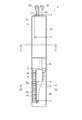
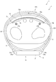
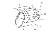
- FIG. 1 is a perspective view showing the configuration of the blood pressure measurement device according to the first embodiment of the present invention.
- FIG. 2 is a perspective view showing the configuration of the blood pressure measurement device.
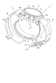
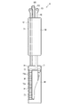
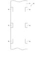
- FIG. 3 is an exploded perspective view of the configuration of the blood pressure measurement device.
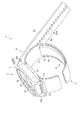
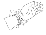
- FIG. 4 is an explanatory diagram showing a state in which the blood pressure measurement device is worn on the wrist.
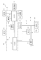
- FIG. 5 is a block diagram showing the configuration of the blood pressure measurement device.
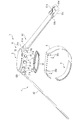
- FIG. 6 is a perspective view showing a configuration of a device body and a curler of the blood pressure measurement device.
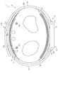
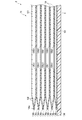
- FIG. 7 is a plan view showing the configuration of the cuff structure of the blood pressure measurement device.
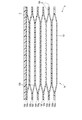
- FIG. 8 is a plan view showing another configuration of the cuff structure of the blood pressure measurement device.
- FIG. 1 is a perspective view showing the configuration of the blood pressure measurement device according to the first embodiment of the present invention.
- FIG. 2 is a perspective view showing the configuration of the blood pressure measurement device.
- FIG. 3 is
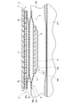
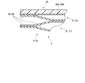
- FIG. 9 is sectional drawing which shows the structure of the belt, curlers, and cuff structure of the same blood pressure measuring device.
- FIG. 10 is a sectional view showing a configuration of a curler and a cuff structure of the blood pressure measurement device.
- FIG. 11 is a cross-sectional view showing a configuration of a curler and a cuff structure of the blood pressure measurement device.
- FIG. 12 is an explanatory diagram showing a configuration when the cuff structure is inflated with the blood pressure measurement device worn on the wrist.
- FIG. 13 is a cross-sectional view showing the configuration when the cuff structure is inflated with the blood pressure measurement device worn on the wrist.
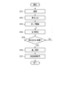
- FIG. 14 is a flow chart showing an example of use of the blood pressure measurement device.
- FIG. 10 is a sectional view showing a configuration of a curler and a cuff structure of the blood pressure measurement device.
- FIG. 11 is a cross-sectional view showing a configuration of a curler and a
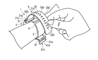
- FIG. 15 is a perspective view showing an example of mounting the blood pressure measuring device on the wrist.
- FIG. 16 is a perspective view showing an example of mounting the blood pressure measuring device on the wrist.
- FIG. 17 is a perspective view showing an example of mounting the blood pressure measuring device on the wrist.
- FIG. 18 is sectional drawing which shows the structure of the curler and cuff structure of the blood-pressure measuring apparatus which concerns on the 2nd Embodiment of this invention.
- FIG. 19 is a cross-sectional view showing a modified example of the configuration of the curler and the cuff structure of the blood pressure measurement device.
- FIG. 20 is a cross-sectional view showing the configuration of another modified example of the curler of the blood pressure measurement device.
- FIG. 21 is a cross-sectional view showing the configuration of another modified example of the curler of the blood pressure measurement device.
- FIG. 22 is a cross-sectional view showing the configuration of another modified example of the curler and the cuff structure of the blood pressure measurement device.
- FIG. 23 is a sectional view showing a configuration of another modified example of the curler and the cuff structure of the blood pressure measurement device.
- FIG. 24 is a perspective view showing the configuration of the blood pressure measurement device according to the third embodiment of the present invention.
- FIG. 25 is a cross-sectional view showing the configuration of the blood pressure measurement device.
- FIG. 26 is a block diagram showing the configuration of the blood pressure measurement device.
- FIG. 1 is a perspective view showing the configuration of the blood pressure measurement device 1 according to the first embodiment of the present invention with the belt 4 closed.
- FIG. 2 is a perspective view showing the configuration of the blood pressure measurement device 1 with the belt 4 opened.
- FIG. 3 is an exploded perspective view showing the configuration of the blood pressure measurement device 1.
- FIG. 4 is an explanatory view showing a cross section of a state in which the blood pressure measurement device 1 is attached to the wrist 200.
- FIG. 5 is a block diagram showing the configuration of the blood pressure measurement device 1.
- FIG. 6 is a perspective view showing the configurations of the device body 3 and the curler 5 of the blood pressure measurement device 1.
- FIG. 7 is a plan view showing the configuration of the cuff structure 6 of the blood pressure measurement device 1.
- FIG. 8 is a plan view showing another configuration of the cuff structure 6 of the blood pressure measurement device 1.
- FIG. 9 is a cross-sectional view showing the configuration of the belt 4, the curler 5 and the cuff structure 6 on the side of the flat cuff 71 of the blood pressure measurement device 1 taken along the line IX-IX in FIG. 7.
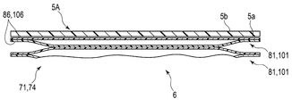
- FIG. 10 is a cross-sectional view of the curler 5 and the cuff structure 6 on the side of the instep cuff 74 of the blood pressure measurement device 1 taken along the line XX in FIG. 7.
- FIG. 9 is a cross-sectional view showing the configuration of the belt 4, the curler 5 and the cuff structure 6 on the side of the flat cuff 71 of the blood pressure measurement device 1 taken along the line IX-IX in FIG. 7.
- FIG. 10 is a cross-sectional view of the curler 5 and the cuff structure 6 on the side of the instep cuff 74 of the blood pressure measurement device 1 taken along the line X
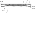
- FIG. 11 is a cross-sectional view showing the configuration of the cuff structure 6 in which the curler 5 and the tube 92 are omitted on the instep cuff 74 side of the blood pressure measurement device 1 taken along the line XI-XI in FIG. 7.
- FIG. 12 is an explanatory diagram showing the configuration when the cuff structure 6 is inflated with the blood pressure measurement device 1 attached to the wrist 200.
- FIG. 13 is a cross-sectional view taken along line XIII-XIII in FIG. 7 showing the configuration when the cuff structure 6 is inflated with the blood pressure measurement device 1 attached to the wrist.
- the blood pressure measurement device 1 is an electronic blood pressure measurement device worn on a living body. This embodiment will be described using an electronic blood pressure measurement device having a form of a wearable device that is worn on the wrist 200 of a living body.
- a blood pressure measurement device 1 includes a device body 3, a belt 4 for fixing the device body 3 to a wrist, a curler 5 arranged between the belt 4 and the wrist, and a flat cuff 71.
- a cuff structure 6 having a sensing cuff 73 and an instep cuff 74, and a fluid circuit 7 for fluidly connecting the device body 3 and the cuff structure 6 are provided.
- the device body 3 includes, for example, a case 11, a display unit 12, an operation unit 13, a pump 14, a flow path unit 15, an opening / closing valve 16, and a pressure sensor 17.
- a power supply unit 18, a vibration motor 19, and a control board 20 are provided.
- the device body 3 supplies a fluid to the cuff structure 6 by the pump 14, the opening / closing valve 16, the pressure sensor 17, the control board 20, and the like.
- the case 11 includes an outer case 31, a windshield 32 that covers an upper opening of the outer case 31, a base portion 33 provided below the inside of the outer case 31, and an outer case 31. And a back cover 35 that covers the lower part.
- the outer case 31 is formed in a cylindrical shape.
- the outer case 31 includes a pair of lugs 31a provided at symmetrical positions in the circumferential direction of the outer peripheral surface, and spring rods 31b provided between the pair of lugs 31a.
- the windshield 32 is, for example, a circular glass plate.
- the base 33 holds the display unit 12, the operation unit 13, the pump 14, the opening / closing valve 16, the pressure sensor 17, the power supply unit 18, the vibration motor 19, and the control board 20.
- the base portion 33 constitutes, for example, a part of the flow passage portion 15 that fluidly connects the pump 14 and the cuff structure body 6.
- the back cover 35 covers the living body side end of the outer case 31.
- the back cover 35 is fixed to the living body side end of the outer case 31 or the base 33 by, for example, four screws 35a.
- the display unit 12 is arranged on the base 33 of the outer case 31 and directly below the windshield 32. As shown in FIG. 5, the display unit 12 is electrically connected to the control board 20.
- the display unit 12 is, for example, a liquid crystal display or an organic electroluminescence display.
- the display unit 12 displays various types of information including blood pressure values such as date and time, systolic blood pressure and diastolic blood pressure, and measurement results such as heart rate.
- the operation unit 13 is configured to be able to input a command from the user.
- the operation unit 13 includes a plurality of buttons 41 provided on the case 11, a sensor 42 that detects an operation of the buttons 41, and a touch panel 43 provided on the display unit 12 or the windshield 32. , Is provided.
- the operation unit 13 is operated by a user to convert a command into an electric signal.
- the sensor 42 and the touch panel 43 are electrically connected to the control board 20 and output an electric signal to the control board 20.
- the plurality of buttons 41 are provided, for example, three.
- the button 41 is supported by the base 33 and protrudes from the outer peripheral surface of the outer case 31.
- the plurality of buttons 41 and the plurality of sensors 42 are supported by the base 33.
- the touch panel 43 is provided integrally with the windshield 32, for example.
- the pump 14 is, for example, a piezoelectric pump.
- the pump 14 compresses air and supplies the compressed air to the cuff structure 6 via the flow path portion 15.
- the pump 14 is electrically connected to the control board 20.
- the flow path portion 15 constitutes a flow path from the pump 14 to the flat cuff 71 and the instep cuff 74, and a flow path from the pump 14 to the sensing cuff 73.
- the flow path portion 15 constitutes a flow path that connects the flat cuff 71 and the instep cuff 74 to the atmosphere, and a flow path that connects the sensing cuff 73 to the atmosphere.
- the flow path portion 15 is an air flow path configured by a hollow portion provided in the base portion 33 and the like, a groove, a tube, and the like.
- the on-off valve 16 opens and closes a part of the flow path section 15. As shown in FIG. 5, for example, a plurality of on-off valves 16 are provided, and a combination of opening and closing of each on-off valve 16 connects the flow path from the pump 14 to the flat cuff 71 and the instep cuff 74, and from the pump 14 to the sensing cuff 73.
- the flow path, the flow path connecting the flat cuff 71 and the instep cuff 74 to the atmosphere, and the flow path connecting the sensing cuff 73 to the atmosphere are selectively opened and closed.
- two on-off valves 16 are used.
- the pressure sensor 17 detects the pressure of the flat cuff 71, the sensing cuff 73, and the instep cuff 74.
- the pressure sensor 17 is electrically connected to the control board 20.
- the pressure sensor 17 converts the detected pressure into an electric signal and outputs it to the control board 20.
- the pressure sensor 17 is provided in a flow path connecting the pump 14 to the flat cuff 71 and the instep cuff 74 and a flow path connecting the pump 14 to the sensing cuff 73.
- the power supply unit 18 is, for example, a secondary battery such as a lithium ion battery.
- the power supply unit 18 is electrically connected to the control board 20.
- the power supply unit 18 supplies power to the control board 20.
- control board 20 includes, for example, a board 51, an acceleration sensor 52, a communication unit 53, a storage unit 54, and a control unit 55.
- the control board 20 is configured by mounting the acceleration sensor 52, the communication section 53, the storage section 54, and the control section 55 on the board 51.
- the substrate 51 is fixed to the base 33 of the case 11 with screws or the like.
- the acceleration sensor 52 is, for example, a triaxial acceleration sensor.
- the acceleration sensor 52 outputs an acceleration signal representing accelerations of the device body 3 in three directions orthogonal to each other to the control unit 55.
- the acceleration sensor 52 is used to measure the activity amount of the living body wearing the blood pressure measurement device 1 from the detected acceleration.
- the communication unit 53 is configured to be capable of transmitting / receiving information to / from an external device by wireless or wired.
- the communication unit 53 transmits, for example, information controlled by the control unit 55 and information such as measured blood pressure value and pulse rate to an external device via a network, and software from the external device via the network.
- the update program or the like is received and sent to the control unit.
- the network is, for example, the Internet, but is not limited to this, and may be a network such as a LAN (Local Area Network) provided in a hospital, or a predetermined standard such as USB. It may be a direct communication with an external device using a cable having a terminal. Therefore, the communication unit 53 may be configured to include a plurality of wireless antennas, micro USB connectors, and the like.
- LAN Local Area Network
- USB Universal Serial Bus
- the storage unit 54 stores program data for controlling the blood pressure measurement device 1 and the fluid circuit 7, setting data for setting various functions of the blood pressure measurement device 1, blood pressure values and pulse rates based on the pressure measured by the pressure sensor 17. Calculated data for calculating is stored in advance.
- the storage unit 54 also stores information such as the measured blood pressure value and pulse.
- the control unit 55 is composed of a single CPU or a plurality of CPUs, and controls the operation of the entire blood pressure measurement device 1 and the operation of the fluid circuit 7.
- the control unit 55 is electrically connected to the display unit 12, the operation unit 13, the pump 14, the open / close valves 16 and the pressure sensors 17, and supplies electric power. Further, the control unit 55 controls the operations of the display unit 12, the pump 14, and the open / close valve 16 based on the electric signals output by the operation unit 13 and the pressure sensor 17.
- the control unit 55 has a main CPU (Central Processing Unit) 56 that controls the operation of the entire blood pressure measurement device 1 and a sub CPU 57 that controls the operation of the fluid circuit 7.
- the main CPU 56 obtains a measurement result such as a blood pressure value such as systolic blood pressure and diastolic blood pressure or a heart rate from the electric signal output from the pressure sensor 17, and outputs an image signal corresponding to the measurement result to the display unit 12.
- a measurement result such as a blood pressure value such as systolic blood pressure and diastolic blood pressure or a heart rate
- the sub CPU 57 drives the pump 14 and the open / close valve 16 to send compressed air to the flat cuff 71 and the sensing cuff 73. Further, the sub CPU 57 controls driving and stopping of the pump 14 and opening / closing of the open / close valve 16 based on the electric signal output from the pressure sensor 17. The sub CPU 57 controls the pump 14 and the opening / closing valve 16 to selectively send compressed air to the flat cuff 71 and the sensing cuff 73, and also selectively depressurize the flat cuff 71 and the sensing cuff 73.
- the belt 4 includes a first belt 61 provided on one pair of lugs 31a and a spring rod 31b, and a second belt 61 provided on the other pair of lugs 31a and a spring rod 31b. And a belt 62.
- the belt 4 is wrapped around the wrist 200 via the curler 5.
- the first belt 61 is called a so-called parent and is formed in a belt shape.
- the first belt 61 is provided at one end of the first belt 61 and is orthogonal to the longitudinal direction of the first belt 61, and the other end of the first belt 61 is orthogonal to the longitudinal direction of the first belt 61. It has two holes 61b and a buckle 61c provided in the second hole 61b.
- the first hole portion 61a has an inner diameter into which the spring rod 31b can be inserted and the first belt 61 can rotate with respect to the spring rod 31b. That is, the first belt 61 is rotatably held in the outer case 31 by being disposed between the pair of lugs 31a and by disposing the first hole portion 61a in the spring rod 31b.
- the second hole 61b is provided at the tip of the first belt 61.
- the buckle 61c has a rectangular frame-shaped frame 61d and a stick 61e rotatably attached to the frame 61d.
- One side of the frame-shaped body 61d to which the stick 61e is attached is inserted into the second hole portion 61b.
- the frame-shaped body 61d is rotatably attached to the first belt 61 via a rod 61e attached to the first belt 61.
- the second belt 62 is a so-called sword tip, and is configured in a belt shape having a width that can be inserted into the frame-shaped body 61d. Further, the second belt 62 has a plurality of small holes 62a into which the sticks 61e are inserted.
- the second belt 62 has a third hole portion 62b that is provided at one end portion and that is orthogonal to the longitudinal direction of the second belt 62.
- the third hole portion 62b has an inner diameter into which the spring rod 31b can be inserted and the second belt 62 can rotate with respect to the spring rod 31b. That is, the second belt 62 is rotatably held in the outer case 31 by being disposed between the pair of lugs 31a and by disposing the third hole portion 62b in the spring rod 31b.
- the second belt 62 is inserted into the frame-shaped body 61d, and the rod 61e attached to the small hole 62a is inserted.
- the belt 4 is integrally connected to the first belt 61 and the second belt 62, and becomes an annular shape following the outer case 31 along the circumferential direction of the wrist 200.
- the curler 5 is formed in a belt shape that curves in the circumferential direction of the wrist.
- the curler 5 is formed such that one end and the other end are separated from each other.
- the outer surface of the curler 5 on one end side is fixed to the back cover 35 of the apparatus body 3.
- the curler 5 is arranged at a position where one end and the other end of the curler 5 project beyond the case back 35. Further, the curlers 5 are separated by a predetermined distance, and one end and the other end are adjacent to each other.
- the curler 5 is fixed to the living body side end of the outer case 31 or the base 33 together with the back cover 35 by using screws 35a or the like. Further, the curler 5 is fixed to the back cover 35 so that one end and the other end are located on one side of the wrist 200 when the blood pressure measurement device 1 is attached to the wrist 200.
- the curler 5 is, for example, a direction orthogonal to the circumferential direction of the wrist, in other words, the circumferential direction of the wrist 200 in a side view from the longitudinal direction of the wrist. It has a shape that curves along.
- the curler 5 extends from the device body 3 to the palm side of the wrist 200 through the back side of the wrist 200 and one side side of the wrist 200, and extends to the other side side of the wrist 200, for example. That is, the curler 5 is arranged along most of the circumferential direction of the wrist 200 by being curved along the circumferential direction of the wrist 200, and both ends thereof are separated by a predetermined distance.
- the curler 5 has hardness having flexibility and shape retention.
- the flexibility means that the shape is deformed in the radial direction when the external force of the belt 4 is applied to the curler 5.
- flexibility means that, when the curler 5 is pressed by the belt 4, the curler 5 approaches the wrist, follows the shape of the wrist, or deforms the shape in a side view so as to follow the shape of the wrist.
- the shape-retaining property means that the curler 5 can maintain a preshaped shape when an external force is not applied.
- the shape-retaining property means that in the present embodiment, the shape of the curler 5 can be maintained to be curved along the circumferential direction of the wrist.
- the curler 5 has a cuff structure 6 arranged on the inner peripheral surface thereof, and holds the cuff structure 6 along the shape of the inner peripheral surface of the curler 5.
- the flat cuff 71 and the instep cuff 74 are arranged on the inner peripheral surface, and the flat cuff 71 and the instep cuff 74 are welded to the outer peripheral surface or the inner peripheral surface by heat, so that the cuff structure 6 Is fixed.
- the flat cuff 71 and the instep cuff are welded to the inner peripheral surface by heat.
- the curler 5 is made of a thermoplastic resin material.
- the curler 5 is made of a material harder than the flat cuff 71 and the instep cuff 74.
- the curler 5 is made of a single material.
- the resin material forming the curler 5 the same material as the resin material forming the flat cuff 71 and the instep cuff 74 is used.
- the resin material forming the curler 5 is composed of a material having good compatibility with the resin material forming the flat cuff 71 and the instep cuff 74 at the time of welding.
- compatibility means a degree of mixing resin materials softened or melted at the time of welding
- good compatibility means that a degree of mixing resin materials softened or melted at the time of welding is suitable bonding, that is, It means that bonding can be performed with the required bonding strength.
- the resin material having good compatibility means that the resin material forming the curler 5 and the resin material forming the flat cuff 71 and the instep cuff 74 are preferably mixed with each other at the time of welding by heat. Two resin materials that can later be integrated with the resin material of the curler 5 and the resin material of the flat cuff 71 or the instep cuff 74 at the welded portion.
- the resin material forming the curler 5 is made of a material having the same softening temperature as or a softening temperature close to that of the resin material forming the flat cuff 71 and the instep cuff 74.
- the resin materials forming the curler 5, the flat cuff 71 and the instep cuff 74 can be appropriately set as long as they are softened and melted when the curler 5 and the cuff structure 6 are welded.
- welder welding, laser welding, heat welding, hot air welding, induction welding, ultrasonic welding, radiation welding, or the like can be used as the welding method of the curler 5, the flat cuff 71, and the instep cuff 74.
- thermoplastic resin material forming the curler 5 examples include thermoplastic polyurethane-based resin (Thermoplastic Poly Urethane, hereinafter referred to as TPU), vinyl chloride resin (PolyVinyl Chloride), ethylene vinyl acetate resin (Ethylene-Vinyl Acetate), heat A thermoplastic polystyrene resin (Thermoplastic PolyStyrene), a thermoplastic polyolefin resin (Thermoplastic PolyOlefin), a thermoplastic polyester resin (ThermoPlastic Polyester), and a thermoplastic polyamide resin (Thermoplastic PolyAmide) can be used.
- the curler 5 is formed to have a thickness of, for example, about 1 mm.
- the cuff structure 6 includes a flat cuff (cuff) 71, a back plate 72, a sensing cuff 73, and an instep cuff (cuff) 74. ing.
- the cuff structure 6 is fixed to the curler 5.
- a flat cuff 71, a back plate 72 and a sensing cuff 73 are stacked and arranged on the curler 5, and an instep cuff 74 is arranged on the curler 5 while being separated from the flat cuff 71, the back plate 72 and the sensing cuff 73. To be done.
- a flat cuff 71, a back plate 72, a sensing cuff 73, and an instep cuff 74 are arranged on the inner surface of the curler 5.
- the cuff structure 6 is fixed to the inner surface on the palm side of the wrist 200 of the curler 5 by laminating the flat cuff 71, the back plate 72, and the sensing cuff 73 in this order from the inner surface of the curler 5 toward the living body.
- an instep cuff 74 is arranged on the inner surface of the wrist 200 of the curler 5 on the back side of the hand.
- Each member of the cuff structure 6 is fixed to a member adjacent in the stacking direction with a double-sided tape or an adhesive.
- the flat cuff 71 is a so-called pressing cuff.
- the flat cuff 71 is fluidly connected to the pump 14 via the flow path portion 15.
- the flat cuff 71 expands to press the back plate 72 and the sensing cuff 73 toward the living body.
- the flat cuff 71 includes a plurality of, for example, two layers of air bags 81.
- the flat cuff 71 is made of the same kind of resin material that has high compatibility with the curler 5 in welding by heat.
- the air bag 81 is a bag-shaped structure, and in the present embodiment, since the blood pressure measurement device 1 is configured to use air by the pump 14, it will be described using the air bag, but other than air.
- the bag-shaped structure may be a fluid bag such as a liquid bag.
- the plurality of air bags 81 are stacked and fluidly communicate with each other in the stacking direction.
- the air bag 81 is formed in a rectangular shape that is long in one direction.
- the air bag 81 is configured by, for example, combining two sheet members 86 that are long in one direction and welding the edges by heat.
- the two-layer air bladder 81 includes a first sheet member 86a and a second sheet bladder 81 that constitutes the first sheet member 86a and the first-layer air bladder 81 from the living body side.
- a sheet member 86b, a third sheet member 86c that is integrally bonded to the second sheet member 86b, and a fourth sheet member 86d that constitutes the third sheet member 86c and the second-layer air bag 81 are provided.
- the two-layer air bag 81 is integrally formed by joining the sheet members 86 of the adjacent air bags 81 by adhesion or welding with a double-sided tape and an adhesive or the like.
- the first sheet member 86a and the second sheet member 86b form the air bag 81 by welding the peripheral portions of the four sides.
- the second sheet member 86b and the third sheet member 86c are arranged to face each other, and each has a plurality of openings 86b1 and 86c1 that fluidly connect the two air bags 81.
- the fourth sheet member 86d is arranged on the curler 5, and is welded to the inner peripheral surface or the outer peripheral surface of the curler 5 by heat.
- the third sheet member 86c and the fourth sheet member 86d form the air bag 81 by welding the peripheral portions of the four sides.
- the back plate 72 is attached to the outer surface of the first sheet member 86a of the flat cuff 71 with an adhesive layer or a double-sided tape.
- the back plate 72 is formed of a resin material in a plate shape.
- the back plate 72 is made of polypropylene, for example, and is formed into a plate shape having a thickness of about 1 mm.
- the back plate 72 has a shape following property.
- the shape-following property refers to a function of allowing the back plate 72 to be deformed so as to follow the shape of the contacted portion of the wrist 200 to be arranged, and the back plate 72 faces the contacted portion of the wrist 200.
- the area of the wrist 200 is referred to, and the contact here includes both direct contact and indirect contact via the sensing cuff 73.
- the back plate 72 has a plurality of grooves 72a extending in a direction orthogonal to the longitudinal direction on both main surfaces of the back plate 72.
- a plurality of grooves 72a are provided on both main surfaces of the back plate 72, respectively.
- the plurality of grooves 72a provided on both main surfaces face each other in the thickness direction of the back plate 72.
- the plurality of grooves 72a are arranged at equal intervals in the longitudinal direction of the back plate 72.
- the part of the back plate 72 having the plurality of grooves 72a is thinner than the part having no groove 72a, so that the part having the plurality of grooves 72a is easily deformed. Therefore, the back plate 72 is deformed following the shape of the wrist 200, and has the shape following property extending in the circumferential direction of the wrist.
- the back plate 72 is formed to have a length that covers the palm side of the wrist 200.
- the back plate 72 transmits the pressing force from the flat cuff 71 to the main surface of the sensing cuff 73 on the back plate 72 side along the shape of the wrist 200.
- the sensing cuff 73 is fixed to the main surface of the back plate 72 on the living body side.
- the sensing cuff 73 directly contacts the region of the wrist 200 where the artery 210 exists, as shown in FIGS. 12 and 13.
- the artery 210 is a radial artery and an ulnar artery.
- the sensing cuff 73 is formed in the same shape as the back plate 72 or in a shape smaller than the back plate 72 in the longitudinal direction and the width direction of the back plate 72.
- the sensing cuff 73 When the sensing cuff 73 is inflated, the sensing cuff 73 compresses the area where the palm side artery 210 of the wrist 200 is present.
- the sensing cuff 73 is pressed toward the living body through the back plate 72 by the expanded flat cuff 71.
- the sensing cuff 73 includes one air bag 91, a tube 92 communicating with the air bag 91, and a connecting portion 93 provided at the tip of the tube 92.
- the sensing cuff 73 has one main surface of the air bag 91 fixed to the back plate 72.
- the sensing cuff 73 is attached to the main surface of the back plate 72 on the living body side with a double-sided tape, an adhesive layer, or the like.
- the air bag 91 is a bag-shaped structure, and in the present embodiment, since the blood pressure measurement device 1 has a configuration in which air is used by the pump 14, it will be described using the air bag, but other than air.
- the bag-shaped structure may be a liquid bag or the like.
- the air bag 91 is formed in a rectangular shape that is long in one direction.
- the air bag 91 is configured by, for example, combining two sheet members 96 that are long in one direction and welding the edges by heat.
- the air bag 91 includes a fifth sheet member 96a and a sixth sheet member 96b from the living body side.
- the tube 92 that is fluidly continuous with the internal space of the air bag 91 is arranged on one side of the fifth sheet member 96a and the sixth sheet member 96b, and is welded. Fixed.
- the peripheral portions of the four sides are welded in a state where the tube 92 is arranged between the fifth sheet member 96a and the sixth sheet member 96b to form the air bag 91.
- the tube 92 is integrally welded.
- the tube 92 is provided at one end of the air bag 91 in the longitudinal direction.
- the tube 92 is provided at the end of the air bag 91 close to the apparatus body 3.
- the tube 92 has a connecting portion 93 at its tip.
- the tube 92 is connected to the flow path portion 15 and constitutes a flow path between the apparatus body 3 and the air bag 91.
- the connection part 93 is connected to the flow path part 15.
- the connecting portion 93 is, for example, a nipple.
- the instep cuff 74 is a so-called pulling cuff.
- the instep cuff 74 is fluidly connected to the pump 14 via the flow path portion 15.
- the back cuff 74 pushes the curler 5 so as to be separated from the wrist 200 by being inflated, thereby pulling the belt 4 and the curler 5 toward the back side of the wrist 200.
- the instep cuff 74 includes a plurality of, for example, six layers of air bags 101, a tube 102 that communicates with the air bag 101, and a connecting portion 103 provided at the tip of the tube 102.
- the instep cuff 74 has an inflated thickness in the inflation direction, in the present embodiment, a direction in which the curler 5 and the wrist 200 face each other, and an inflated thickness in the inflation direction of the flat cuff 71, and sensing. It is configured to be thicker than the thickness of the cuff 73 in the inflating direction. That is, the air bag 101 of the instep cuff 74 has a layered structure larger than the air bag 81 of the flat cuff 71 and the air bag 91 of the sensing cuff 73, and has a thickness when inflated from the curler 5 toward the wrist 200. It is thicker than the flat cuff 71 and the sensing cuff 73.
- the air bag 101 is a bag-shaped structure, and in the present embodiment, since the blood pressure measurement device 1 has a configuration in which air is used by the pump 14, it will be described using an air bag, but other than air.
- the bag-shaped structure may be a fluid bag such as a liquid bag.
- the plurality of air bags 101 are stacked and fluidly communicate with each other in the stacking direction.
- the air bag 101 is formed in a rectangular shape that is long in one direction.
- the air bag 101 is configured by, for example, combining two sheet members 106 that are long in one direction and welding the edges by heat.
- the six-layer air bag 101 includes a seventh sheet member 106a, an eighth sheet member 106b, a ninth sheet member 106c, and a tenth sheet from the living body side.
- the six-layer air bag 101 is integrally configured by joining the sheet members 106 of the adjacent air bags 101 by adhesion or welding with a double-sided tape and an adhesive or the like.
- the seventh sheet member 106a and the eighth sheet member 106b form the air bag 101 of the first layer by welding the peripheral portions of the four sides.
- the eighth sheet member 106b and the ninth sheet member 106c are arranged facing each other and are integrally bonded.
- the eighth sheet member 106b and the ninth sheet member 106c have a plurality of openings 106b1 and 106c1 that fluidly connect the adjacent air bags 101.
- the ninth sheet member 106c and the tenth sheet member 106d form the air bag 101 of the second layer by welding the peripheral portions of the four sides.
- the tenth sheet member 106d and the eleventh sheet member 106e are arranged facing each other and are integrally bonded.
- the tenth sheet member 106d and the eleventh sheet member 106e have a plurality of openings 106d1 and 106e1 that fluidly connect the adjacent air bags 101.
- the eleventh sheet member 106e and the twelfth sheet member 106f constitute the air bag 101 of the third layer by welding the peripheral portions of the four sides.
- the twelfth sheet member 106f and the thirteenth sheet member 106g are arranged facing each other and are integrally bonded.
- the twelfth sheet member 106f and the thirteenth sheet member 106g have a plurality of openings 106f1 and 106g1 for fluidly connecting the adjacent air bags 101.
- the thirteenth sheet member 106g and the fourteenth sheet member 106h form the air bag 101 of the fourth layer by welding the peripheral portions of the four sides.
- the 14th sheet member 106h and the 15th sheet member 106i are arranged so as to face each other and are integrally bonded.
- the fourteenth sheet member 106h and the fifteenth sheet member 106i have a plurality of openings 106h1 and 106i1 for fluidly connecting the adjacent air bags 101.
- the fifteenth sheet member 106i and the sixteenth sheet member 106j form the air bag 101 of the fifth layer by welding the peripheral portions of the four sides.
- the 16th sheet member 106j and the 17th sheet member 106k are arranged so as to face each other and are integrally bonded.
- the sixteenth sheet member 106j and the seventeenth sheet member 106k have a plurality of openings 106j1 and 106k1 for fluidly connecting the adjacent air bags 101.
- the seventeenth sheet member 106k and the eighteenth sheet member 106l have their peripheral portions welded in a rectangular frame shape to form the sixth-layer air bag 101.
- the tube 102 that is fluidly continuous with the internal space of the air bag 101 is arranged on one side of the seventeenth sheet member 106k and the eighteenth sheet member 106l, and is fixed by welding.
- the seventeenth sheet member 106k and the eighteenth sheet member 106l are welded at their peripheral portions in a rectangular frame shape while the tube 102 is arranged between the seventeenth sheet member 106k and the eighteenth sheet member 106l to form the air bag 101.
- the tube 102 is integrally welded.
- such a sixth layer air bag 101 is configured integrally with the second layer air bag 81 of the flat cuff 71. That is, the seventeenth sheet member 106k is integrally formed with the third sheet member 86c, and the eighteenth sheet member 106l is integrally formed with the fourth sheet member 86d.
- the third sheet member 86c and the seventeenth sheet member 106k form a rectangular sheet member that is long in one direction
- the eighteenth sheet member 106l and the fourth sheet member 86d are rectangular sheets that are long in one direction.
- a shaped sheet member is configured.
- these sheet members are overlapped with each other, and one end portion side is formed into a rectangular frame shape and is welded except a part of one side on the other end portion side.
- the air bag 81 of the second layer of the flat cuff 71 is configured.
- the other end has a rectangular frame shape, and is welded except for a part of one side on one end to form the air bag 101 of the sixth layer of the instep cuff 74.
- the second-layer air bag 81 and the sixth-layer air bag 101 are fluidly continuous because part of one side facing each other is not welded.
- the tube 102 is connected to one air bag 101 out of the six layers of air bags 101 and is provided at one end of the air bag 101 in the longitudinal direction.
- the tube 102 is provided on the curler 5 side of the six-layer air bag 101 and at an end portion near the apparatus body 3.
- the tube 102 has a connecting portion 103 at the tip.
- the tube 102 constitutes a flow path between the device body 3 and the air bag 101 in the fluid circuit 7.
- the connection portion 103 is, for example, a nipple.
- the instep cuff 74 has been described as having a part integrally formed with the flat cuff 71 and being fluidly continuous with the flat cuff 71, but the present invention is not limited to this. .
- the instep cuff 74 may be configured separately from the flat cuff 71 and may be fluidly discontinuous with the flat cuff 71.
- the flat cuff 71 is further provided with a tube and a connecting portion similarly to the sensing cuff 73 and the instep cuff 74, and also in the fluid circuit 7, the fluid is supplied to the flat cuff 71.
- the flow path, the check valve, and the pressure sensor may be connected.
- Each sheet member 86, 96, 106 forming the flat cuff 71, the sensing cuff 73, and the instep cuff 74 is made of a thermoplastic resin material.
- the thermoplastic resin material is a thermoplastic elastomer.
- thermoplastic resin material forming the sheet members 86, 96, 106 examples include thermoplastic polyurethane resin (Thermoplastic Poly Urethane, hereinafter referred to as TPU), vinyl chloride resin (PolyVinyl Chloride), ethylene vinyl acetate resin (Ethylene- VinylAcetate), thermoplastic polystyrene resin (Thermoplastic PolyStyrene), thermoplastic polyolefin resin (Thermoplastic PolyOlefin), thermoplastic polyester resin (ThermoPlastic Polyester), and thermoplastic polyamide resin (Thermoplastic PolyAmide) can be used.
- TPU thermoplastic polyurethane resin
- TPU thermoplastic Polyurethane resin
- Vinyl Chloride PolyVinyl Chloride
- ethylene vinyl acetate resin Ethylene- VinylAcetate
- thermoplastic polystyrene resin Thermoplastic PolyStyrene
- thermoplastic polyolefin resin Thermoplastic PolyOlefin
- At least the sheet members 86 and 106 that are welded to the curler 5 among the plurality of sheet members 86 and 106 that form the air bags 81 and 101 are made of the same material as the curler 5. To be done.
- a molding method such as T-die extrusion molding or injection molding is used.
- the sheet members 86, 96, 106 are molded by each molding method, then sized to a predetermined shape, and the sized pieces are joined by welding or the like to form the bag-shaped structures 81, 91, 101.
- a welding method a high-frequency welder or laser welding is used.
- the curler 5 is required to have hardness having flexibility and shape retention.
- the cuff structure 6 is configured such that the air bags 81, 91, 101 are inflated, and the air bag 81 is formed by welding the sheet members 86, 96, 106, and the air bag of the flat cuff 71.
- the air bag 101 of 81 and the instep cuff 74 is welded to the curler 5.
- At least the curler 5, the sheet member 86 of the air bag 81 of the flat cuff 71 and the sheet member 106 of the air bag 101 of the instep cuff 74, which are welded to the curler 5, have compatibility at the time of welding, and
- the materials are made of the same kind of material so that the softening temperature has a suitable combination.
- the flat cuff 71 and the instep cuff 74 may be configured so that the sheet members 86 and 106 welded to the curler 5 are made of the same material as the curler 5. However, it is preferable that all the sheet members 86 are made of the same material because the adjacent sheet members 86 and 106 that are stacked are welded when the air bags 81 and 101 are formed.
- the curler 5 is made of thermoplastic polyurethane resin (TPU) 1174D
- the flat cuff 71 and the instep cuff 74 are made of thermoplastic polyurethane resin (TPU) R195A. If the curler 5, the flat cuff 71, the instep cuff 74, and the adjacent sheet members 86, 96, 106 can be suitably welded, the sheet members 86, 96, 106 have a single-layer structure. It may have a multilayer structure.
- the fluid circuit 7 is composed of a case 11, a pump 14, a flow path portion 15, an opening / closing valve 16, a pressure sensor 17, a flat cuff 71, a sensing cuff 73, and an instep cuff 74.
- the two on-off valves 16 used in the fluid circuit 7 are a first on-off valve 16A and a second on-off valve 16B, and the two pressure sensors 17 are a first pressure sensor 17A and a second pressure sensor 17B. A specific example will be described.
- the fluid circuit 7 is configured by, for example, a first flow path 7a that connects the flat cuff 71 and the instep cuff 74 from the pump 14 and a midway portion of the first flow path 7a.
- the pump 14 includes a second flow path 7b that connects the sensing cuff 73 and a third flow path 7c that connects the first flow path 7a and the atmosphere.
- the first flow path 7a includes a first pressure sensor 17A.
- a first opening / closing valve 16A is provided between the first flow path 7a and the second flow path 7b.
- the second flow path 7b includes a second pressure sensor 17B.
- a second opening / closing valve 16B is provided between the first flow path 7a and the third flow path 7c.
- the first opening / closing valve 16A and the second opening / closing valve 16B are closed so that only the first flow path 7a is connected to the pump 14, and the pump 14 and the flat cuff 71 are fluidly connected.
- the first opening / closing valve 16A is opened and the second opening / closing valve 16B is closed, so that the first flow path 7a and the second flow path 7b are connected, and the pump 14 and the instep cuff 74 and the instep cuff 74 are connected.
- the flat cuff 71, the pump 14 and the sensing cuff 73 are fluidly connected.
- FIG. 14 is a flowchart showing an example of blood pressure measurement using the blood pressure measurement device 1, and shows both the user's operation and the operation of the control unit 55.
- 15 to 17 show an example in which the user wears the blood pressure measurement device 1 on the wrist 200.
- the user wears the blood pressure measurement device 1 on the wrist 200 (step ST1).
- the user inserts one of the wrists 200 into the curler 5, as shown in FIG.
- the sensing cuff 73 is arranged in the region where the palm side artery 210 of the wrist 200 exists.
- the device body 3 and the back cuff 74 are arranged on the back side of the wrist 200.
- the user pulls the second belt 62 to bring the member on the inner peripheral surface side of the curler 5, that is, the cuff structure 6 into close contact with the wrist 200, and inserts the rod 61e attached to the small hole 62a.
- the first belt 61 and the second belt 62 are connected, and the blood pressure measurement device 1 is attached to the wrist 200.
- the user operates the operation unit 13 to input a command corresponding to the start of blood pressure measurement.
- the operation unit 13 that has performed the input operation of the command outputs an electric signal corresponding to the start of measurement to the control unit 55 (step ST2).
- the control unit 55 receives the electric signal, for example, the first opening / closing valve 16A is opened, the second opening / closing valve 16B is closed, the pump 14 is driven, and the first passage 7a and the second passage 7b are passed through.
- the compressed air is supplied to the flat cuff 71, the sensing cuff 73, and the instep cuff 74 (step ST3).
- the flat cuff 71, the sensing cuff 73, and the instep cuff 74 start to inflate.
- the first pressure sensor 17A and the second pressure sensor 17B detect the pressures of the flat cuff 71, the sensing cuff 73, and the instep cuff 74, respectively, and output an electric signal corresponding to this pressure to the control unit 55 (step ST4).
- the control unit 55 determines whether the pressure in the internal space of the flat cuff 71, the sensing cuff 73 and the instep cuff 74 has reached a predetermined pressure for blood pressure measurement based on the received electric signal (step ST5). ).
- the control unit 55 turns on the first opening / closing valve 16A. Closed, and compressed air is supplied through the first flow path 7a.
- the control unit 55 stops the driving of the pump 14 (YES in step ST5).
- the flat cuff 71 and the instep cuff 74 have been sufficiently inflated, and the inflated flat cuff 71 presses the back plate 72.
- the instep cuff 74 presses the curler 5 in the direction away from the wrist 200
- the belt 4, the curler 5 and the device body 3 move in the direction away from the wrist 200, and as a result, the flat cuff 71, The back plate 72 and the sensing cuff 73 are pulled toward the wrist 200.
- the belt 4, the curler 5 and the device body 3 move in the direction away from the wrist 200 due to the expansion of the instep cuff 74, the belt 4 and the curler 5 move toward both sides of the wrist 200,
- the belt 4, the curler 5, and the main body 3 of the apparatus move while being in close contact with both sides of 200.
- the curler 5 may be configured so as to indirectly contact the skin of the wrist 200 via the sheet members 86 and 106 as long as it can pull the skin of the wrist 200.
- the sensing cuff 73 is inflated by supplying a predetermined amount of air so that the internal pressure becomes the pressure required to measure the blood pressure, and the back plate 72 pressed by the flat cuff 71 causes the sensing cuff 73 to move to the wrist 200. It is pressed toward. Therefore, the sensing cuff 73 presses the artery 210 in the wrist 200 and closes the artery 210 as shown in FIG.
- control unit 55 controls the inside of the flat cuff 71, for example, by controlling the second opening / closing valve 16B and repeating opening / closing of the second opening / closing valve 16B or adjusting the opening degree of the second opening / closing valve 16B.
- the pressure in the space is increased.
- the control unit 55 obtains measurement results such as blood pressure values such as systolic blood pressure and diastolic blood pressure and heart rate based on the electric signal output from the second pressure sensor 17B (step ST6).
- the control unit 55 outputs the image signal corresponding to the obtained measurement result to the display unit 12 and displays the measurement result on the display unit 12 (step ST7).
- the control unit 55 opens the first opening / closing valve 16A and the second opening / closing valve 16B after the blood pressure measurement is completed.
- the display unit 12 Upon receiving the image signal, the display unit 12 displays the measurement result on the screen. The user confirms the measurement result by visually recognizing the display unit 12. After the measurement, the user removes the rod 61e attached to the small hole 62a, removes the second belt 62 from the frame-shaped body 61d, and removes the wrist 200 from the curler 5, thereby removing the blood pressure measurement device 1 from the wrist 200. Remove.
- the blood pressure measurement device 1 has a configuration in which the curler 5, the curler 5, the flat cuff 71, and the instep cuff 74 are joined by heat welding. Further, in the blood pressure measurement device 1, at least the welded portions of the curler 5, the flat cuff 71, and the instep cuff 74 are made of a thermoplastic resin material that is compatible with each other and has the same or a similar softening temperature. Is.
- suitable welding means welding in which material is broken, not when the curler 5 and the flat cuff 71 and the instep cuff 74 are subjected to a tensile load until the joined portions are separated from each other, rather than when the joined portions are separated at the interface.
- the curler 5 and the cuff structure 6 have high durability.
- the cuff structure 6 is joined to the curler 5 with high joining strength, the cuff structure 6 repeatedly expands and contracts in a posture along the inner peripheral surface of the curler 5, so that the wrinkles of the cuff structure 6 are wrinkled. It is possible to suppress the occurrence of breakage and to prevent the pressure distribution in the cuff structure 6 from being biased.
- the blood pressure measuring device 1 can directly weld the curler 5, the flat cuff 71, and the instep cuff 74 by using a resin material that can be suitably heat-welded for the curler 5, the flat cuff 71, and the instep cuff 74. Therefore, as shown in FIG. 11, the curler 5 and the cuff structure 6 only need to be welded again at any part where the curler 5 and the flat cuff 71 and the instep cuff 74 abut, and it is not necessary to provide an adhesive layer. , You don't have to take a joining margin for gluing or sewing.
- the dimension in the thickness direction increases by the amount of the adhesive layer.
- a joining method such as sewing or riveting
- a separate member is required, so that the size in the width direction and the thickness direction increases by the amount of the separate member.
- the curler 5 and the cuff structure 6 of the present embodiment can be joined by welding, the dimension in the width direction and the dimension in the thickness direction that occur when joining with an adhesive layer or another member does not increase. It is possible to prevent an increase in size due to. As a result, the blood pressure measurement device 1 can prevent the curler 5 and the cuff structure 6 from becoming large in outer shape.
- the blood pressure measurement device 1 can be downsized, and highly accurate blood pressure measurement can be performed stably for a long period of time.
- the curler 5 is made of the same kind of material as the resin material of the flat cuff 71 and the instep cuff 74, so that it can be made of one kind of resin material, which facilitates the manufacture. . Further, since the curler 5 can be welded to the cuff structure 6 by heat at all portions, the curler 5 has a high degree of freedom in designing the welded portion.
- the blood pressure measurement device 1 is configured such that the cuff structure 6 is welded to the curler 5 by heat, so that the dimension of the cuff structure 6 in the width direction is equal to or less than the dimension of the curler 5 in the width direction. You can Therefore, the cuff structure 6 can be arranged at the same position as the curler 5 or inside the curler 5, and the blood pressure measurement device 1 can be downsized.
- the blood pressure measuring device requires a bonding margin when bonding with an adhesive layer or another member. It is also conceivable to increase the outer dimensions of the blood pressure measurement device even if the joint margin is secured by reducing the width of the cuff in the width direction of the curler 5. However, if the width of the cuff is reduced, the measurement accuracy in blood pressure measurement is reduced. However, in the blood pressure measurement device 1 of the present embodiment, since the curler 5 and the cuff structure 6 are welded by heat, the width of each cuff 71, 74 of the cuff structure 6 can be matched with the width of the curler 5. As a result, the cuff structure 6 can be joined to the curler 5 and the widths of the cuffs 71 and 74 can be secured, so that the blood pressure measurement device 1 can be downsized while maintaining the measurement accuracy in blood pressure measurement.
- the curler 5 can be downsized by heat-welding the flat cuff 71 and the instep cuff 74 made of the same material.
- the blood pressure measurement device 1 according to the second embodiment is configured to use the curler 5A as a composite material, and in this respect, the blood pressure measurement according to the first embodiment in which the curler 5 is made of a single material.
- the same configurations as those of the blood pressure measurement device 1 according to the first embodiment described above will be denoted by the same reference numerals, and description and Illustration is omitted as appropriate.
- the blood pressure measurement device 1 includes a device body 3, a belt 4 for fixing the device body 3 to a wrist, a curler 5A arranged between the belt 4 and the wrist, and a flat cuff 71.
- a cuff structure 6 having a sensing cuff 73 and an instep cuff 74, and a fluid circuit 7 for fluidly connecting the device body 3 and the cuff structure 6 are provided.
- the curler 5A is made of a plurality of materials, and the portion that is welded to the cuff structure 6 by heat is made of the same material as the cuff structure 6.
- the curler 5A is formed in a band shape that curves along the circumferential direction of the wrist.
- the curler 5A is formed such that one end and the other end are separated from each other.
- the curler 5A has, for example, an outer surface on one end side fixed to the back cover 35 of the apparatus body 3.
- the curler 5 ⁇ / b> A is arranged at a position where one end and the other end of the curler 5 ⁇ / b> A project from the back cover 35. Further, the curlers 5A are separated by a predetermined distance, and one end and the other end are adjacent to each other.
- the curler 5A is fixed to the living body side end of the outer case 31 or the base 33 together with the back cover 35 using a screw 35a or the like.
- the curler 5 ⁇ / b> A is fixed to the back cover 35 so that one end and the other end are located on one side of the wrist 200 when the blood pressure measurement device 1 is attached to the wrist 200.
- the curler 5A has, for example, a shape that is curved along the circumferential direction of the wrist 200 in a side view from the longitudinal direction of the wrist, that is, a direction orthogonal to the circumferential direction of the wrist.
- the curler 5A extends from the device body 3 to the palm side of the wrist 200 through the back side of the wrist 200 and one side side of the wrist 200, and extends to the other side side of the wrist 200, for example. That is, the curler 5A is curved along the circumferential direction of the wrist 200, is arranged over most of the circumferential direction of the wrist 200, and has both ends spaced apart with a predetermined interval.
- the curler 5A has hardness having flexibility and shape retention.
- the flexibility means that the shape is deformed in the radial direction when the external force of the belt 4 is applied to the curler 5A.
- the flexibility means that when the curler 5A is pressed by the belt 4, the curler 5A is close to the wrist, conforms to the shape of the wrist, or is deformed in a side view so as to follow the shape of the wrist.
- the shape-retaining property means that the curler 5A can maintain a pre-shaped shape when an external force is not applied.
- the shape-retaining property means that, in the present embodiment, the shape of the curler 5A can be maintained to be curved along the circumferential direction of the wrist.
- the curler 5A has a cuff structure 6 arranged on the inner peripheral surface thereof, and holds the cuff structure 6 along the inner peripheral surface shape of the curler 5A.
- the flat cuff 71 and the instep cuff 74 are arranged on the inner peripheral surface, and the flat cuff 71 and the instep cuff 74 are welded to the inner peripheral surface or the outer peripheral surface by heat, whereby the cuff structure 6 is formed. Is fixed.
- Curler 5A is made of a thermoplastic resin material.
- the curler 5A includes a first portion 5a including a region where the flat cuff 71 and the upper cuff 74 are welded, and a second portion 5b other than the first portion 5a.
- the first portion 5a and the second portion 5b are integrally formed by resin molding such as injection molding.
- the first portion 5a is set in a region where at least the flat cuff 71 and the instep cuff 74 are welded.
- the first portion 5a is made of the same material as the flat cuff 71 and the instep cuff 74. If the first portion 5a can exhibit the function of the curler 5A together with the second portion 5b, and the flat cuff 71 and the instep cuff 74 can be welded, the range, shape, etc. can be set appropriately.
- the second part 5b constitutes a part of the curler 5A other than the first part 5a.
- the second portion 5b is provided to obtain flexibility and shape retention of the curler 5A.
- the range, shape, and the like of the second portion 5b can be appropriately set as long as they can exhibit the function of the curler 5A together with the first portion 5a.
- the second portion 5b is made of a material that is harder than the first portion 5a and has a lower elastic modulus than that of the first portion 5a.
- the material forming the second part 5b for example, polypropylene (PolyproPylene), polyethylene terephthalate (PolyEthyleneTerephthalate), polyethylene naphthalate (PolyEthylene Naphthalate) can be used. Further, the second portion 5b may be formed of a metal material such as a metal plate.
- the curler 5A is provided with the first portion 5a on the outer peripheral surface side and the inner peripheral surface. It has a two-layer structure in which the second portion 5b is provided on the side.
- the blood pressure measurement device 1 having the curler 5A configured as described above can be downsized and stabilizes the blood pressure measurement with high accuracy for a long period of time, like the blood pressure measurement device 1 according to the first embodiment described above. It becomes possible to do it.
- the curler 5A is made of a composite material in which the portion to be welded to the cuff structure 6 is the same material as the material of the portion to be welded to the cuff structure 6 and the other portions are different materials.
- the curler 5A can be suitably heat-welded to the cuff structure 6 and can easily obtain the flexibility and shape retention required for the curler 5A. Further, since the curler 5A can be heat-welded to the cuff structure 6 by the first portion 5a, and the function required for the curler 5A can be obtained by the second portion 5b, the curler 5A can be provided depending on the required function. The material of the second portion 5b can be selected appropriately. As described above, the curler 5A has a high degree of freedom in selecting materials.
- the present invention is not limited to the above embodiments.
- the curler 5A is made of a composite material
- a structure having a two-layer structure in which the first portion 5a is provided on the outer peripheral surface side and the second portion 5b is provided on the inner peripheral surface side is described.
- the curler 5A may be configured such that the outer surface side is configured by the first portion 5a and the center side is configured by the second portion 5b as the core material.
- the curler 5A and the cuff structure 6 are configured to be welded at the edges along the longitudinal direction of the curler 5A and the cuff structure 6, and the curler 5A in the longitudinal direction. Both edge portions may be constituted by the first portion 5a and the central portion may be constituted by the second portion 5b. Further, as shown in FIG. 21, the curler 5A may have a configuration in which a plurality of first portions 5a are arranged at the portions where welding is performed.
- the blood pressure measurement device 1 includes a joining piece 99 that is arranged on the outer peripheral surface of the curler 5A and is joined to the curler 5A on the flat cuff 71 and the instep cuff 74.
- the first portion 5a may be arranged on the outer peripheral surface side of the curler 5A.
- the joining piece 99 has, for example, a width of the sheet members 86, 106 of at least the first layer of the air bags 81, 101 larger than the width of the curler 5A, and the two edges of the sheet members 86, 106 in the width direction are folded back. Composed of.
- the joining piece 99 is formed of a part of the cuff structure 6 and the joining piece 99 is folded back toward the outer peripheral surface of the curler 5A to be joined, the cuff structure 6 is formed on the outer peripheral surface of the curler 5A. Even if the welding is performed, it is possible to suppress an increase in the widthwise dimension of the curler 5A, and the blood pressure measurement device 1 can be downsized.
- the welding of the curler 5A and the air bags 81 and 101 may be performed on both sides of the curlers 5 and 5A.
- the air bag 81, 101 is provided with a joining piece 99, the joining piece 99 and the outer peripheral surface of the curler 5A are welded, and the sheet members 86, 106 and the inner peripheral surface of the curler 5A are welded. By doing so, welding is performed on both surfaces of the curlers 5 and 5A. With such a configuration, the curlers 5 and 5A and the cuff structure 6 can be joined more firmly.
- the present invention is not limited to this.
- the curler 5 faces the curler 5.
- the sheet members 86 and 106 may be multi-layered sheet members 86A and 106A, and the resin material on the curler 5 side of the multi-layered sheet members 86A and 106A may be the same kind of material as the resin material of the curler 5.
- the timing of opening and closing the first opening / closing valve 16A and the second opening / closing valve 16B at the time of blood pressure measurement is not limited to the example described above, and can be set as appropriate.
- the blood pressure measurement device 1 has described the example of calculating the blood pressure by the pressure measured in the pressurizing process of the flat cuff 71, but the present invention is not limited to this, and the blood pressure may be calculated in the depressurizing process. The blood pressure may be calculated in both the pressurizing process and the depressurizing process.
- the flat cuff 71 has been described with the configuration in which the air bag 81 is formed by each sheet member 86, but the present invention is not limited to this.
- the air bag 81 may include other configurations.
- the back plate 72 has been described as having a plurality of grooves 72a, but the present invention is not limited to this.
- the back plate 72 can appropriately set the number and depth of the plurality of grooves 72a in order to manage the easiness of deformation and the like, and may be configured to include a member that suppresses the deformation. .
- the blood pressure measuring device 1 has been described as a structure in which the curlers 5 and 5A and the cuff structure 6 are joined by heat welding, but the invention is not limited to this.
- the blood pressure measurement device 1 performs a step of temporarily fixing the cuff structure 6 to the curlers 5 and 5A with an adhesive layer such as a double-sided tape in advance in the manufacturing process of joining the cuff structure 6 to the curlers 5 and 5A, and then It may be configured such that heat welding is performed.
- the blood pressure measurement device 1 may have a configuration in which the curlers 5 and 5A and a part of the cuff structure 6 are joined by an adhesive layer such as a double-sided tape.
- the blood pressure measurement device 1 having these configurations is configured to join the curlers 5 and 5A and the cuff structure 6 by temporary fixing with an adhesive layer or partial joining and joining by heat welding, Also requires less adhesive layer. Further, since the temporary fixing and a part of the joining can be performed at a portion where the curlers 5 and 5A and the cuff structure 6 come into contact with each other, it is not necessary to separately provide a joining margin for joining using the adhesive layer. Therefore, the blood pressure measurement device 1 can be downsized.
- the blood pressure measurement device 1 has been described using the example of the wearable device worn on the wrist 200, but the invention is not limited to this.
- the blood pressure measurement device may be a blood pressure measurement device 1B that measures blood pressure by wrapping it around the upper arm.
- the blood pressure measurement device 1B will be described as a third embodiment with reference to FIGS. 24 to 26.
- the same configurations as those of the blood pressure measurement device 1 according to the above-described first embodiment will be described with the same reference numerals, and the description and illustration thereof will be appropriately omitted.
- the blood pressure measurement device 1B includes a device body 3B and a cuff structure 6B.
- the device body 3B includes, for example, a case 11B, a display unit 12, an operation unit 13, a pump 14, a flow path unit 15, an opening / closing valve 16, a pressure sensor 17, a power supply unit 18, and a control board 20. And are equipped with.
- the apparatus main body 3B has one pump 14, an on-off valve 16 and a pressure sensor 17, respectively.
- the case 11B has a box shape, for example.
- the case 11B has a mounting portion 11a for fixing the cuff structure 6B.
- the mounting portion 11a is, for example, an opening provided on the back surface of the case 11B.
- the cuff structure 6B includes a curler 5B made of a thermoplastic resin material and a pressing cuff 71B made of a thermoplastic resin material provided on the living body side of the curler 5B. , A bag-shaped cover body 76 made of cloth or the like in which the curler 5B and the pressing cuff 71B are arranged. The cuff structure 6B is wrapped around the upper arm.
- the curler 5B has, for example, a protrusion 5c fixed to the mounting portion 11a.
- the pressing cuff 71B includes an air bag 81B and a tube provided in the air bag 81B and fluidly connected to the flow path portion 15.
- the pressing cuff 71B is housed in the bag-shaped cover body 76 together with the curler 5B, and is joined to the inner surface of the curler 5B by heat welding.
- the air bag 81B is formed in a rectangular shape that is long in one direction.
- the air bag 81B is configured by, for example, combining two sheet members 86 that are long in one direction and welding the edges by heat.
- the air bag 81B includes a first sheet member 86a and a second sheet member 86b that configures the first sheet member 86a and the air bag 81B from the living body side.
- the curler 5B and the air bag 81B of the pressing cuff 71B are joined by welding. Further, in the curler 5B and the pressing cuff 71B, at least the portions to be welded are made of the same material, similarly to the curlers 5 and 5A, the flat cuff 71, and the instep cuff 74 described above.
- the curler 5B and the pressing cuff 71B are joined by welding, and at least the resin material of the portion where the curler 5B and the pressing cuff 71B are welded is the same material.
- the blood pressure measurement device 1 can be downsized and stably perform highly accurate blood pressure measurement for a long period of time, like the blood pressure measurement device 1 according to the first embodiment described above. .
- the back plate 72 is attached to the outer surface of the first sheet member 86a of the flat cuff 71 and the main surface of the sensing cuff 73 on the living body side with an adhesive layer, a double-sided tape, or the like.
- the back plate 72 may be configured to be welded to the flat cuff 71 and the sensing cuff 73 by heat, like the curler 5 according to the first embodiment or the curler 5A according to the second embodiment described above. Good.
- the back plate 72 may be entirely formed of the same material as the flat cuff 71 and the sensing cuff 73, similarly to the curler 5, and, similarly to the curler 5A.
- the portion welded to the flat cuff 71 and the sensing cuff 73 may be formed of at least the same material as the flat cuff 71 and the sensing cuff 73.
- the back plate 72 may be configured such that it is welded to only one of the flat cuff 71 and the sensing cuff 73 by heat, and is joined to the other by sticking.
- the present invention is not limited to the above-described embodiment, and can be variously modified in an implementation stage without departing from the gist thereof. Further, the respective embodiments may be appropriately combined and implemented, in which case the combined effects can be obtained. Further, the above-described embodiment includes various inventions, and various inventions can be extracted by a combination selected from a plurality of disclosed constituent features. For example, even if some constituent elements are deleted from all the constituent elements shown in the embodiment, if the problem can be solved and the effect can be obtained, the structure in which the constituent elements are deleted can be extracted as the invention.
- Control board 31 ... Outer case 31a ... Lug 31b ... Spring rod 32 ... Wind shield 33 ... Base part 35 ... Back cover 35a ... Screw 41 ... Button 42 ... Sensor 43 ... Touch panel 51 ... Substrate 52 ... Acceleration sensor 53 ... Communication part 54 ... Storage part 55 ... Control part 56 ... Main CPU 57 ... Sub CPU 61 ... 1st belt 61a ... 1st hole 61b ... 2nd hole 61c ... Buckle 61d ... Frame-like body 61e ... Stick rod 62 ... 2nd belt 62a ... Small hole 62b ... 3rd hole 71 ... Flat cuff (cuff) ) 71B ... Pressing cuff 72 ...
Landscapes
- Health & Medical Sciences (AREA)
- Life Sciences & Earth Sciences (AREA)
- Cardiology (AREA)
- Vascular Medicine (AREA)
- Surgery (AREA)
- Medical Informatics (AREA)
- Physics & Mathematics (AREA)
- Veterinary Medicine (AREA)
- Biophysics (AREA)
- Pathology (AREA)
- Engineering & Computer Science (AREA)
- Biomedical Technology (AREA)
- Heart & Thoracic Surgery (AREA)
- Public Health (AREA)
- Molecular Biology (AREA)
- General Health & Medical Sciences (AREA)
- Animal Behavior & Ethology (AREA)
- Dentistry (AREA)
- Physiology (AREA)
- Ophthalmology & Optometry (AREA)
- Measuring Pulse, Heart Rate, Blood Pressure Or Blood Flow (AREA)
Priority Applications (3)
| Application Number | Priority Date | Filing Date | Title |
|---|---|---|---|
| DE112019004118.5T DE112019004118T5 (de) | 2018-10-15 | 2019-09-27 | Blutdruckmessvorrichtung |
| CN201980059775.7A CN112689472B (zh) | 2018-10-15 | 2019-09-27 | 血压测定装置 |
| US17/216,878 US20210212580A1 (en) | 2018-10-15 | 2021-03-30 | Blood pressure measurement device |
Applications Claiming Priority (2)
| Application Number | Priority Date | Filing Date | Title |
|---|---|---|---|
| JP2018194347A JP7154932B2 (ja) | 2018-10-15 | 2018-10-15 | 血圧測定装置 |
| JP2018-194347 | 2018-10-15 |
Related Child Applications (1)
| Application Number | Title | Priority Date | Filing Date |
|---|---|---|---|
| US17/216,878 Continuation US20210212580A1 (en) | 2018-10-15 | 2021-03-30 | Blood pressure measurement device |
Publications (1)
| Publication Number | Publication Date |
|---|---|
| WO2020080074A1 true WO2020080074A1 (ja) | 2020-04-23 |
Family
ID=70283185
Family Applications (1)
| Application Number | Title | Priority Date | Filing Date |
|---|---|---|---|
| PCT/JP2019/038367 Ceased WO2020080074A1 (ja) | 2018-10-15 | 2019-09-27 | 血圧測定装置 |
Country Status (5)
| Country | Link |
|---|---|
| US (1) | US20210212580A1 (enExample) |
| JP (1) | JP7154932B2 (enExample) |
| CN (1) | CN112689472B (enExample) |
| DE (1) | DE112019004118T5 (enExample) |
| WO (1) | WO2020080074A1 (enExample) |
Families Citing this family (2)
| Publication number | Priority date | Publication date | Assignee | Title |
|---|---|---|---|---|
| JP7718098B2 (ja) * | 2021-05-19 | 2025-08-05 | オムロンヘルスケア株式会社 | 血圧測定装置 |
| JP7741055B2 (ja) * | 2022-12-19 | 2025-09-17 | シチズン時計株式会社 | ソフトカフ装着補助具 |
Citations (6)
| Publication number | Priority date | Publication date | Assignee | Title |
|---|---|---|---|---|
| JPS61100228A (ja) * | 1984-10-24 | 1986-05-19 | コーリン電子株式会社 | 血圧測定用カフ |
| JPH07124127A (ja) * | 1993-06-18 | 1995-05-16 | Omron Corp | 血圧計用腕帯 |
| JPH09238910A (ja) * | 1996-03-08 | 1997-09-16 | Citizen Watch Co Ltd | 手首血圧計のカフ |
| JP2006158876A (ja) * | 2004-12-10 | 2006-06-22 | Omron Healthcare Co Ltd | 血圧計用カフおよびこれを備えた血圧計 |
| JP2013158347A (ja) * | 2012-02-01 | 2013-08-19 | Omron Healthcare Co Ltd | 血圧情報測定装置用検出ユニットおよび血圧情報測定装置 |
| JP2018102859A (ja) * | 2016-12-28 | 2018-07-05 | オムロン株式会社 | 血圧計および血圧測定方法並びに機器 |
Family Cites Families (12)
| Publication number | Priority date | Publication date | Assignee | Title |
|---|---|---|---|---|
| US6036718A (en) * | 1998-07-02 | 2000-03-14 | Welch Allyn, Inc. | Bladderless blood pressure cuff |
| JP3952957B2 (ja) * | 2003-01-22 | 2007-08-01 | オムロンヘルスケア株式会社 | 手首式血圧計用カフ |
| JP4595526B2 (ja) * | 2004-12-20 | 2010-12-08 | オムロンヘルスケア株式会社 | 血圧計用カフおよび血圧計 |
| JP5486202B2 (ja) * | 2009-03-02 | 2014-05-07 | テルモ株式会社 | 血圧計及びその製造方法 |
| US20150165338A1 (en) * | 2012-05-18 | 2015-06-18 | Jinwook Choe | Flying toy wrist band |
| WO2015031501A1 (en) * | 2013-08-27 | 2015-03-05 | Polyera Corporation | Attachable device having a flexible electronic component |
| US9212863B1 (en) * | 2014-03-25 | 2015-12-15 | Brian F. Weinstock | Toy projectile system and method that utilizes bi-stable ribbon spring projectiles |
| WO2016056144A1 (en) * | 2014-10-10 | 2016-04-14 | Nec Corporation | Blood pressure meter and cuff |
| JP6172341B2 (ja) * | 2016-01-04 | 2017-08-02 | オムロンヘルスケア株式会社 | 生体情報測定装置 |
| US10898084B2 (en) * | 2016-03-31 | 2021-01-26 | The Regents Of The University Of California | Vital signs monitor |
| FR3051345B1 (fr) * | 2016-05-19 | 2018-09-28 | Spengler Sas | Systeme de sphygmomanometre |
| JP7118852B2 (ja) * | 2018-10-15 | 2022-08-16 | オムロン株式会社 | 血圧測定装置 |
-
2018
- 2018-10-15 JP JP2018194347A patent/JP7154932B2/ja active Active
-
2019
- 2019-09-27 CN CN201980059775.7A patent/CN112689472B/zh active Active
- 2019-09-27 WO PCT/JP2019/038367 patent/WO2020080074A1/ja not_active Ceased
- 2019-09-27 DE DE112019004118.5T patent/DE112019004118T5/de active Pending
-
2021
- 2021-03-30 US US17/216,878 patent/US20210212580A1/en active Pending
Patent Citations (6)
| Publication number | Priority date | Publication date | Assignee | Title |
|---|---|---|---|---|
| JPS61100228A (ja) * | 1984-10-24 | 1986-05-19 | コーリン電子株式会社 | 血圧測定用カフ |
| JPH07124127A (ja) * | 1993-06-18 | 1995-05-16 | Omron Corp | 血圧計用腕帯 |
| JPH09238910A (ja) * | 1996-03-08 | 1997-09-16 | Citizen Watch Co Ltd | 手首血圧計のカフ |
| JP2006158876A (ja) * | 2004-12-10 | 2006-06-22 | Omron Healthcare Co Ltd | 血圧計用カフおよびこれを備えた血圧計 |
| JP2013158347A (ja) * | 2012-02-01 | 2013-08-19 | Omron Healthcare Co Ltd | 血圧情報測定装置用検出ユニットおよび血圧情報測定装置 |
| JP2018102859A (ja) * | 2016-12-28 | 2018-07-05 | オムロン株式会社 | 血圧計および血圧測定方法並びに機器 |
Also Published As
| Publication number | Publication date |
|---|---|
| JP2020062088A (ja) | 2020-04-23 |
| CN112689472A (zh) | 2021-04-20 |
| CN112689472B (zh) | 2025-03-18 |
| DE112019004118T5 (de) | 2021-05-06 |
| JP7154932B2 (ja) | 2022-10-18 |
| US20210212580A1 (en) | 2021-07-15 |
Similar Documents
| Publication | Publication Date | Title |
|---|---|---|
| WO2020095990A1 (ja) | 血圧測定装置 | |
| JP7019415B2 (ja) | 血圧測定装置 | |
| JP7150595B2 (ja) | 血圧測定装置用カフカバー | |
| WO2020137478A1 (ja) | 血圧測定装置用カフの製造方法 | |
| JP7237576B2 (ja) | 血圧測定装置 | |
| JP6896610B2 (ja) | 血圧測定装置 | |
| JP6976842B2 (ja) | 血圧測定装置 | |
| WO2020080074A1 (ja) | 血圧測定装置 | |
| JP7118852B2 (ja) | 血圧測定装置 | |
| JP7175738B2 (ja) | 血圧測定装置 | |
| CN112804939B (zh) | 血压测定装置 | |
| WO2020090314A1 (ja) | 血圧測定装置 | |
| WO2020137476A1 (ja) | 血圧測定装置 | |
| JP7202886B2 (ja) | 血圧測定装置 | |
| JP7019416B2 (ja) | 血圧測定装置 | |
| JP6896611B2 (ja) | 血圧測定装置 | |
| WO2020137474A1 (ja) | 血圧測定装置 |
Legal Events
| Date | Code | Title | Description |
|---|---|---|---|
| 121 | Ep: the epo has been informed by wipo that ep was designated in this application |
Ref document number: 19872373 Country of ref document: EP Kind code of ref document: A1 |
|
| 122 | Ep: pct application non-entry in european phase |
Ref document number: 19872373 Country of ref document: EP Kind code of ref document: A1 |
|
| WWG | Wipo information: grant in national office |
Ref document number: 201980059775.7 Country of ref document: CN |