WO2020090314A1 - 血圧測定装置 - Google Patents
血圧測定装置 Download PDFInfo
- Publication number
- WO2020090314A1 WO2020090314A1 PCT/JP2019/038388 JP2019038388W WO2020090314A1 WO 2020090314 A1 WO2020090314 A1 WO 2020090314A1 JP 2019038388 W JP2019038388 W JP 2019038388W WO 2020090314 A1 WO2020090314 A1 WO 2020090314A1
- Authority
- WO
- WIPO (PCT)
- Prior art keywords
- cuff
- blood pressure
- curler
- sheet member
- measurement device
- Prior art date
Links
Images


Classifications
-
- A—HUMAN NECESSITIES
- A61—MEDICAL OR VETERINARY SCIENCE; HYGIENE
- A61B—DIAGNOSIS; SURGERY; IDENTIFICATION
- A61B5/00—Measuring for diagnostic purposes; Identification of persons
- A61B5/02—Detecting, measuring or recording pulse, heart rate, blood pressure or blood flow; Combined pulse/heart-rate/blood pressure determination; Evaluating a cardiovascular condition not otherwise provided for, e.g. using combinations of techniques provided for in this group with electrocardiography or electroauscultation; Heart catheters for measuring blood pressure
- A61B5/021—Measuring pressure in heart or blood vessels
- A61B5/022—Measuring pressure in heart or blood vessels by applying pressure to close blood vessels, e.g. against the skin; Ophthalmodynamometers
- A61B5/02233—Occluders specially adapted therefor
-
- A—HUMAN NECESSITIES
- A61—MEDICAL OR VETERINARY SCIENCE; HYGIENE
- A61B—DIAGNOSIS; SURGERY; IDENTIFICATION
- A61B5/00—Measuring for diagnostic purposes; Identification of persons
- A61B5/68—Arrangements of detecting, measuring or recording means, e.g. sensors, in relation to patient
- A61B5/6801—Arrangements of detecting, measuring or recording means, e.g. sensors, in relation to patient specially adapted to be attached to or worn on the body surface
- A61B5/6802—Sensor mounted on worn items
- A61B5/681—Wristwatch-type devices
-
- A—HUMAN NECESSITIES
- A61—MEDICAL OR VETERINARY SCIENCE; HYGIENE
- A61B—DIAGNOSIS; SURGERY; IDENTIFICATION
- A61B5/00—Measuring for diagnostic purposes; Identification of persons
- A61B5/02—Detecting, measuring or recording pulse, heart rate, blood pressure or blood flow; Combined pulse/heart-rate/blood pressure determination; Evaluating a cardiovascular condition not otherwise provided for, e.g. using combinations of techniques provided for in this group with electrocardiography or electroauscultation; Heart catheters for measuring blood pressure
- A61B5/021—Measuring pressure in heart or blood vessels
- A61B5/02141—Details of apparatus construction, e.g. pump units or housings therefor, cuff pressurising systems, arrangements of fluid conduits or circuits
-
- A—HUMAN NECESSITIES
- A61—MEDICAL OR VETERINARY SCIENCE; HYGIENE
- A61B—DIAGNOSIS; SURGERY; IDENTIFICATION
- A61B5/00—Measuring for diagnostic purposes; Identification of persons
- A61B5/02—Detecting, measuring or recording pulse, heart rate, blood pressure or blood flow; Combined pulse/heart-rate/blood pressure determination; Evaluating a cardiovascular condition not otherwise provided for, e.g. using combinations of techniques provided for in this group with electrocardiography or electroauscultation; Heart catheters for measuring blood pressure
- A61B5/021—Measuring pressure in heart or blood vessels
- A61B5/022—Measuring pressure in heart or blood vessels by applying pressure to close blood vessels, e.g. against the skin; Ophthalmodynamometers
- A61B5/02233—Occluders specially adapted therefor
- A61B5/02241—Occluders specially adapted therefor of small dimensions, e.g. adapted to fingers
-
- A—HUMAN NECESSITIES
- A61—MEDICAL OR VETERINARY SCIENCE; HYGIENE
- A61B—DIAGNOSIS; SURGERY; IDENTIFICATION
- A61B5/00—Measuring for diagnostic purposes; Identification of persons
- A61B5/68—Arrangements of detecting, measuring or recording means, e.g. sensors, in relation to patient
- A61B5/6801—Arrangements of detecting, measuring or recording means, e.g. sensors, in relation to patient specially adapted to be attached to or worn on the body surface
- A61B5/6813—Specially adapted to be attached to a specific body part
- A61B5/6824—Arm or wrist
-
- A—HUMAN NECESSITIES
- A61—MEDICAL OR VETERINARY SCIENCE; HYGIENE
- A61B—DIAGNOSIS; SURGERY; IDENTIFICATION
- A61B5/00—Measuring for diagnostic purposes; Identification of persons
- A61B5/68—Arrangements of detecting, measuring or recording means, e.g. sensors, in relation to patient
- A61B5/6801—Arrangements of detecting, measuring or recording means, e.g. sensors, in relation to patient specially adapted to be attached to or worn on the body surface
- A61B5/6844—Monitoring or controlling distance between sensor and tissue
-
- A—HUMAN NECESSITIES
- A61—MEDICAL OR VETERINARY SCIENCE; HYGIENE
- A61B—DIAGNOSIS; SURGERY; IDENTIFICATION
- A61B2560/00—Constructional details of operational features of apparatus; Accessories for medical measuring apparatus
- A61B2560/02—Operational features
- A61B2560/0204—Operational features of power management
- A61B2560/0214—Operational features of power management of power generation or supply
-
- A—HUMAN NECESSITIES
- A61—MEDICAL OR VETERINARY SCIENCE; HYGIENE
- A61B—DIAGNOSIS; SURGERY; IDENTIFICATION
- A61B2562/00—Details of sensors; Constructional details of sensor housings or probes; Accessories for sensors
- A61B2562/02—Details of sensors specially adapted for in-vivo measurements
- A61B2562/0247—Pressure sensors
-
- A—HUMAN NECESSITIES
- A61—MEDICAL OR VETERINARY SCIENCE; HYGIENE
- A61B—DIAGNOSIS; SURGERY; IDENTIFICATION
- A61B2562/00—Details of sensors; Constructional details of sensor housings or probes; Accessories for sensors
- A61B2562/16—Details of sensor housings or probes; Details of structural supports for sensors
- A61B2562/164—Details of sensor housings or probes; Details of structural supports for sensors the sensor is mounted in or on a conformable substrate or carrier
-
- A—HUMAN NECESSITIES
- A61—MEDICAL OR VETERINARY SCIENCE; HYGIENE
- A61B—DIAGNOSIS; SURGERY; IDENTIFICATION
- A61B5/00—Measuring for diagnostic purposes; Identification of persons
- A61B5/02—Detecting, measuring or recording pulse, heart rate, blood pressure or blood flow; Combined pulse/heart-rate/blood pressure determination; Evaluating a cardiovascular condition not otherwise provided for, e.g. using combinations of techniques provided for in this group with electrocardiography or electroauscultation; Heart catheters for measuring blood pressure
- A61B5/021—Measuring pressure in heart or blood vessels
- A61B5/022—Measuring pressure in heart or blood vessels by applying pressure to close blood vessels, e.g. against the skin; Ophthalmodynamometers
- A61B5/0235—Valves specially adapted therefor
Definitions
- the blood pressure measuring device described above a wearable device worn on the wrist has been considered recently. For this reason, it is not preferable that the blood pressure measuring device be increased in size by increasing the joining margin provided on the cuff or curler.
- the joint margin is increased, so that the joint strength of the cuff and the curler can be improved.
- the blood pressure measurement device in which the front first facing portion is configured to have a shape wider in the width direction than other portions of the curler. According to this aspect, by increasing the joint area, the blood pressure measuring device is increased in size by making the first facing portion, which increases the joint area in the curler, a region facing the end of the outer case in the thickness direction. It can be prevented.
- the case 11 includes an outer case 31, a windshield 32 that covers an upper opening of the outer case 31, a base portion 33 provided below the inside of the outer case 31, and a lower side of the outer case 31. And a back cover 35 that covers the.
- the base 33 holds the display unit 12, the operation unit 13, the pump 14, the opening / closing valve 16, the pressure sensor 17, the power supply unit 18, the vibration motor 19, and the control board 20. Further, the base portion 33 constitutes, for example, a part of the flow passage portion 15 that fluidly connects the pump 14 and the cuff structure body 6.
- the back cover 35 covers the living body side end of the outer case 31.
- the back cover 35 is fixed to the living body side end of the outer case 31 or the base 33 by, for example, four screws 35a.
- the surface shape of the back surface 35b of the back cover 35 is circular because the outer case 31 is formed in a cylindrical shape.
- the diameter of the back cover 35 is smaller than the diameter of the outer case 31. In other words, the length of the back cover 35 along the width direction of the curler 5 is shorter than the length of the outer case 31 along the width direction of the curler 5.
- the operation unit 13 is configured to be able to input a command from the user.
- the operation unit 13 includes a plurality of buttons 41 provided on the case 11, a sensor 42 that detects an operation of the buttons 41, and a touch panel 43 provided on the display unit 12 or the windshield 32. , Is provided.
- the operation unit 13 is operated by a user to convert a command into an electric signal.
- the sensor 42 and the touch panel 43 are electrically connected to the control board 20 and output an electric signal to the control board 20.
- the pump 14 is, for example, a piezoelectric pump.
- the pump 14 compresses air and supplies the compressed air to the cuff structure 6 via the flow path portion 15.
- the pump 14 is electrically connected to the control board 20.
- the on-off valve 16 opens and closes a part of the flow path section 15.
- a plurality of on-off valves 16 are provided, for example, as shown in FIG. 5, and a combination of opening and closing of each on-off valve 16 connects the pump 14 to the flat cuff 71 and the instep cuff 74, and connects the pump 14 to the sensing cuff 73.
- the flow path, the flow path from the flat cuff 71 and the instep cuff 74 to the atmosphere, and the flow path from the sensing cuff 73 to the atmosphere are selectively opened and closed.
- two on-off valves 16 are used.
- the pressure sensor 17 detects the pressure of the flat cuff 71, the sensing cuff 73, and the instep cuff 74.
- the pressure sensor 17 is electrically connected to the control board 20.
- the pressure sensor 17 converts the detected pressure into an electric signal and outputs it to the control board 20.
- the pressure sensor 17 is provided in a flow path connecting the pump 14 to the flat cuff 71 and the instep cuff 74 and a flow path connecting the pump 14 to the sensing cuff 73.
- the power supply unit 18 is, for example, a secondary battery such as a lithium ion battery.
- the power supply unit 18 is electrically connected to the control board 20.
- the power supply unit 18 supplies power to the control board 20.
- the acceleration sensor 52 is, for example, a triaxial acceleration sensor.
- the acceleration sensor 52 outputs an acceleration signal representing accelerations of the device body 3 in three directions orthogonal to each other to the control unit 55.
- the acceleration sensor 52 is used to measure the activity amount of the living body wearing the blood pressure measurement device 1 from the detected acceleration.
- the network is, for example, the Internet, but is not limited to this, and may be a network such as a LAN (Local Area Network) provided in a hospital, or a predetermined standard such as USB. It may be a direct communication with an external device using a cable having terminals. Therefore, the communication unit 53 may be configured to include a plurality of wireless antennas and micro USB connectors.
- LAN Local Area Network
- USB Universal Serial Bus
- the control unit 55 has a main CPU (Central Processing Unit) 56 that controls the operation of the entire blood pressure measurement device 1 and a sub CPU 57 that controls the operation of the fluid circuit 7.
- the main CPU 56 obtains a measurement result such as a blood pressure value such as systolic blood pressure and diastolic blood pressure or a heart rate from the electric signal output from the pressure sensor 17, and outputs an image signal corresponding to the measurement result to the display unit 12. .
- a measurement result such as a blood pressure value such as systolic blood pressure and diastolic blood pressure or a heart rate
- the sub CPU 57 drives the pump 14 and the opening / closing valve 16 to send compressed air to the flat cuff 71 and the sensing cuff 73. Further, the sub CPU 57 controls driving and stopping of the pump 14 and opening / closing of the open / close valve 16 based on the electric signal output from the pressure sensor 17. The sub CPU 57 controls the pump 14 and the opening / closing valve 16 to selectively send compressed air to the flat cuff 71 and the sensing cuff 73, and selectively depressurize the flat cuff 71 and the sensing cuff 73.
- the first belt 61 is called a so-called parent and is configured in a belt shape.
- the first belt 61 is provided at one end of the first belt 61 and is orthogonal to the longitudinal direction of the first belt 61, and the other end of the first belt 61 is orthogonal to the longitudinal direction of the first belt 61. It has two holes 61b and a buckle 61c provided in the second hole 61b.
- the first hole portion 61a has an inner diameter into which the spring rod 31b can be inserted and the first belt 61 can rotate with respect to the spring rod 31b. That is, the first belt 61 is rotatably held in the outer shell case 31 between the pair of lugs 31a and by disposing the first hole portion 61a in the spring rod 31b.
- the second hole 61b is provided at the tip of the first belt 61.
- the buckle 61c has a rectangular frame-shaped frame 61d and a stick 61e rotatably attached to the frame 61d.
- One side of the frame-shaped body 61d, to which the stick 61e is attached, is inserted into the second hole portion 61b and is rotatably attached with respect to the first belt 61.
- the second belt 62 is a so-called sword tip, and is configured in a belt shape having a width that can be inserted into the frame-shaped body 61d. Further, the second belt 62 has a plurality of small holes 62a into which the sticks 61e are inserted.
- the second belt 62 has a third hole portion 62b provided at one end portion thereof and orthogonal to the longitudinal direction of the second belt 62.
- the third hole 62b has an inner diameter into which the spring rod 31b can be inserted and the second belt 62 can rotate with respect to the spring rod 31b. That is, the second belt 62 is rotatably held in the outer case 31 by being disposed between the pair of lugs 31a and by disposing the third hole portion 62b in the spring rod 31b.
- the curler 5, as shown in FIG. 4, is configured in a band shape that curves along the circumferential direction of the wrist.
- the curler 5 is formed such that one end and the other end are separated from each other.
- the curler 5 has, for example, an outer surface on one end side fixed to the back cover 35 of the apparatus body 3.
- the curler 5 is arranged at a position where one end and the other end of the curler 5 project beyond the case back 35. Further, the curlers 5 are separated by a predetermined distance, and one end and the other end are adjacent to each other.
- the curler 5 has a first facing portion 5a.
- the first facing portion 5 a faces the back cover 35.
- the first facing portion 5a is arranged in the axial direction of the outer case 31 at the end of the outer case.
- the curler 5 is, for example, a circumference of the wrist 200 in a side view from a direction orthogonal to the circumferential direction of the wrist, in other words, a longitudinal direction of the wrist 200. It has a shape that curves along a direction.
- the curler 5 extends from the device body 3 to the palm side of the wrist 200 through the back side of the wrist 200 and one side side of the wrist 200, and extends to the other side side of the wrist 200, for example. That is, the curler 5 is arranged along most of the circumferential direction of the wrist 200 by being curved along the circumferential direction of the wrist 200, and both ends thereof are separated by a predetermined distance.
- the curler 5 has hardness having flexibility and shape retention.
- the flexibility means that the shape is deformed in the radial direction when an external force of the belt 4 is applied to the curler 5.
- flexibility means that when the curler 5 is pressed by the belt 4, the curler 5 approaches the wrist, follows the shape of the wrist, or deforms the shape in a side view so as to follow the shape of the wrist.
- the shape-retaining property means that the curler 5 can maintain a preshaped shape when an external force is not applied.
- the outer shape retaining property means that in the present embodiment, the shape of the curler 5 can be maintained to be curved along the circumferential direction of the wrist.
- the curler 5 has a cuff structure 6 arranged on the inner peripheral surface thereof, and holds the cuff structure 6 along the inner peripheral surface shape of the curler 5.
- the flat cuff 71 and the instep cuff 74 are arranged on the inner peripheral surface, and the flat cuff 71 and the instep cuff 74 are joined by the joining member 8.
- the curler 5 is made of a resin material.
- the curler 5 is formed of, for example, a thermoplastic resin material, specifically, polypropylene.
- the curler 5 is formed to have a thickness of, for example, about 1 mm.
- the cuff structure 6 includes a flat cuff (cuff) 71, a back plate 72, a sensing cuff 73, and an instep cuff (cuff) 74. ing.
- the cuff structure 6 is fixed to the curler 5.
- a flat cuff 71, a back plate 72 and a sensing cuff 73 are stacked and arranged on the curler 5, and an instep cuff 74 is arranged on the curler 5 while being separated from the flat cuff 71, the back plate 72 and the sensing cuff 73. To be done.
- a flat cuff 71, a back plate 72, a sensing cuff 73, and an instep cuff 74 are arranged on the inner surface of the curler 5.
- the cuff structure 6 is fixed on the palm-side inner surface of the wrist 200 of the curler 5 by laminating the flat cuff 71, the back plate 72, and the sensing cuff 73 in this order from the inner surface of the curler 5 toward the living body.
- an instep cuff 74 is arranged on the inner surface of the back side of the wrist 200 of the curler 5.
- Each member of the cuff structure 6 is fixed to a member adjacent in the stacking direction with a double-sided tape or an adhesive.
- the flat cuff 71 is a so-called pressing cuff.
- the flat cuff 71 is fluidly connected to the pump 14 via the flow path portion 15.
- the flat cuff 71 expands to press the back plate 72 and the sensing cuff 73 toward the living body.
- the flat cuff 71 includes a plurality of, for example, two layers of air bags 81, and a plurality of insertion holes 82 provided in the air bag 81 of the two layers of air bags 81 arranged on the curler 5 side.
- the air bag 81 is a bag-shaped structure, and in the present embodiment, since the blood pressure measurement device 1 is configured to use air by the pump 14, it will be described using the air bag, but other than air.
- the bag-shaped structure may be a fluid bag such as a liquid bag.
- the plurality of air bags 81 are stacked and fluidly communicate with each other in the stacking direction.
- the air bag 81 is formed in a rectangular shape that is long in one direction.
- the air bag 81 is configured by, for example, combining two sheet members 86 that are long in one direction and welding the edges by heat. That is, the air bag 81 has a welded portion 81a in which the peripheral portions of the four sides are welded.
- the two-layer air bladder 81 includes a first sheet member 86a and a second sheet bladder 81 that constitutes the first sheet member 86a and the first-layer air bag 81 from the living body side.
- a sheet member 86b, a third sheet member 86c that is integrally bonded to the second sheet member 86b, and a fourth sheet member 86d that constitutes the third sheet member 86c and the second-layer air bag 81 are provided.
- the two-layer air bag 81 is integrally configured by joining the sheet members 86 of the adjacent air bags 81 by double-sided tape, adhesive bonding or welding.
- the first sheet member 86a and the second sheet member 86b form the air bag 81 by welding the peripheral portions of the four sides.
- the second sheet member 86b and the third sheet member 86c are arranged to face each other, and each has a plurality of openings 86b1 and 86c1 that fluidly connect the two air bags 81.
- the third sheet member 86c and the fourth sheet member 86d form the air bag 81 by welding the peripheral portions of the four sides.
- the back plate 72 is attached to the outer surface of the first sheet member 86a of the flat cuff 71 with an adhesive layer, double-sided tape or the like.
- the back plate 72 is formed of a resin material in a plate shape.
- the back plate 72 is made of polypropylene, for example, and is formed into a plate shape having a thickness of about 1 mm.
- the back plate 72 has a shape following property.
- the shape-following property refers to a function of allowing the back plate 72 to be deformed so as to follow the shape of the contacted portion of the wrist 200 to be arranged, and the back plate 72 faces the contacted portion of the wrist 200.
- the area of the wrist 200 is referred to, and the contact here includes both direct contact and indirect contact via the sensing cuff 73.
- the back plate 72 has a plurality of grooves 72a extending in a direction orthogonal to the longitudinal direction on both main surfaces of the back plate 72.
- a plurality of grooves 72a are provided on both main surfaces of the back plate 72, respectively.
- the plurality of grooves 72a provided on both main surfaces face each other in the thickness direction of the back plate 72.
- the plurality of grooves 72a are arranged at equal intervals in the longitudinal direction of the back plate 72.
- the back plate 72 is formed to have a length that covers the palm side of the wrist 200.
- the back plate 72 transmits the pressing force from the flat cuff 71 to the main surface of the sensing cuff 73 on the back plate 72 side while conforming to the shape of the wrist 200.
- the sensing cuff 73 is fixed to the main surface of the back plate 72 on the living body side.
- the sensing cuff 73 is in direct contact with the region of the wrist 200 where the artery 210 is present, as shown in FIGS. 9 and 14.
- the artery 210 is a radial artery and an ulnar artery.
- the sensing cuff 73 is formed in the same shape as the back plate 72 or in a shape smaller than the back plate 72 in the longitudinal direction and the width direction of the back plate 72.
- the sensing cuff 73 When the sensing cuff 73 is inflated, the sensing cuff 73 presses the area where the palm side artery 210 of the wrist 200 is present.
- the sensing cuff 73 is pressed toward the living body by the expanded flat cuff 71 via the back plate 72.
- the sensing cuff 73 includes one air bag 91, a tube 92 that communicates with the air bag 91, and a connecting portion 93 provided at the tip of the tube 92.
- the sensing cuff 73 has one main surface of the air bag 91 fixed to the back plate 72.
- the sensing cuff 73 is attached to the main surface of the back plate 72 on the living body side with a double-sided tape, an adhesive layer, or the like.
- the air bag 91 is a bag-shaped structure, and in the present embodiment, since the blood pressure measurement device 1 is configured to use air by the pump 14, the description will be given using the air bag, but other than air.
- the bag-shaped structure may be a liquid bag or the like.
- the air bag 91 is formed in a rectangular shape that is long in one direction.
- the air bag 91 is configured by, for example, combining two sheet members 96 that are long in one direction and welding the edges by heat.
- the air bag 91 includes a fifth sheet member 96a and a sixth sheet member 96b from the living body side.
- the tube 92 that is fluidly continuous with the internal space of the air bag 91 is arranged on one side of the fifth sheet member 96a and the sixth sheet member 96b, and is welded. Fixed.
- the peripheral portions of the four sides are welded in a state where the tube 92 is arranged between the fifth sheet member 96a and the sixth sheet member 96b to form the air bag 91.
- the tube 92 is integrally welded.
- the tube 92 is provided at one end of the air bag 91 in the longitudinal direction.
- the tube 92 is provided at an end portion of the air bag 91 near the apparatus body 3.
- the tube 92 has a connecting portion 93 at its tip.
- the tube 92 is connected to the flow path portion 15 and constitutes a flow path between the apparatus body 3 and the air bag 91.
- the connection part 93 is connected to the flow path part 15.
- the connecting portion 93 is, for example, a nipple.
- the instep cuff 74 is a so-called pulling cuff.
- the instep cuff 74 is fluidly connected to the pump 14 via the flow path portion 15.
- the instep cuff 74 expands to press the curler 5 so as to separate from the wrist 200, thereby pulling the belt 4 and the curler 5 toward the back side of the wrist 200.
- the instep cuff 74 includes a plurality of, for example, six layers of air bags 101, a tube 102 that communicates with the air bag 101, and a connecting portion 103 provided at the tip of the tube 102.
- the instep cuff 74 is in the inflating direction, in the present embodiment, the direction in which the curler 5 and the wrist 200 are opposed to each other, and the inflated thickness is the inflated thickness in the inflating direction of the flat cuff 71, and the sensing. It is configured to be thicker than the thickness of the cuff 73 in the inflating direction. That is, the air bag 101 of the instep cuff 74 has a layered structure larger than that of the air bag 81 of the flat cuff 71 and the air bag 91 of the sensing cuff 73, and has a thickness when inflated from the curler 5 toward the wrist 200. It is thicker than the flat cuff 71 and the sensing cuff 73.
- the air bag 101 is a bag-shaped structure, and in the present embodiment, since the blood pressure measuring device 1 has a configuration in which air is used by the pump 14, it will be described using an air bag, but other than air.
- the bag-shaped structure may be a fluid bag such as a liquid bag.
- the plurality of air bags 101 are stacked and fluidly communicate with each other in the stacking direction.
- the air bag 101 is formed in a rectangular shape that is long in one direction.
- the air bag 101 is configured by, for example, combining two sheet members 106 that are long in one direction and welding the edges by heat. That is, the air bag 101 has a welded portion 101a in which the peripheral portions of the four sides are welded.
- the six-layer air bag 101 includes a seventh sheet member 106a, an eighth sheet member 106b, a ninth sheet member 106c, and a tenth sheet member 106d from the living body side.
- the six-layered air bag 101 is integrally configured by joining the sheet members 106 of the adjacent air bags 101 by adhering or welding with a double-sided tape, an adhesive or the like.
- the seventh sheet member 106a and the eighth sheet member 106b form the air bag 101 of the first layer by welding the peripheral portions of the four sides.
- the eighth sheet member 106b and the ninth sheet member 106c are arranged facing each other and are integrally bonded.
- the eighth sheet member 106b and the ninth sheet member 106c have a plurality of openings 106b1 and 106c1 that fluidly connect the adjacent air bags 101.
- the ninth sheet member 106c and the tenth sheet member 106d constitute the second-layer air bag 101 by welding the peripheral portions of the four sides.
- the tenth sheet member 106d and the eleventh sheet member 106e are arranged facing each other and are integrally bonded.
- the tenth sheet member 106d and the eleventh sheet member 106e have a plurality of openings 106d1 and 106e1 that fluidly connect the adjacent air bags 101.
- the eleventh sheet member 106e and the twelfth sheet member 106f constitute the third-layer air bag 101 by welding the peripheral portions of the four sides.
- the twelfth sheet member 106f and the thirteenth sheet member 106g are arranged facing each other and are integrally bonded.
- the twelfth sheet member 106f and the thirteenth sheet member 106g have a plurality of openings 106f1 and 106g1 for fluidly connecting the adjacent air bags 101.
- the thirteenth sheet member 106g and the fourteenth sheet member 106h form the fourth-layer air bag 101 by welding the peripheral portions of the four sides.
- the 14th sheet member 106h and the 15th sheet member 106i are arranged to face each other and are integrally bonded.
- the fourteenth sheet member 106h and the fifteenth sheet member 106i have a plurality of openings 106h1 and 106i1 that fluidly connect the adjacent air bags 101.
- the fifteenth sheet member 106i and the sixteenth sheet member 106j form the fifth-layer air bag 101 by welding the peripheral portions of the four sides.
- the 16th sheet member 106j and the 17th sheet member 106k are arranged so as to face each other and are integrally bonded.
- the sixteenth sheet member 106j and the seventeenth sheet member 106k have a plurality of openings 106j1 and 106k1 that fluidly connect the adjacent air bags 101.
- the seventeenth sheet member 106k and the eighteenth sheet member 106l form the sixth-layer air bag 101 by welding the peripheral portions in a rectangular frame shape.
- the eighteenth sheet member 106l is arranged on the curler 5 side.
- the tube 102 that is fluidly continuous with the internal space of the air bag 101 is arranged on one side of the seventeenth sheet member 106k and the eighteenth sheet member 106l, and is fixed by welding.
- the seventeenth sheet member 106k and the eighteenth sheet member 106l are welded at their peripheral portions in a rectangular frame shape while the tube 102 is arranged between the seventeenth sheet member 106k and the eighteenth sheet member 106l to form the air bag 101.
- the tube 102 is integrally welded by molding.
- such a sixth layer air bag 101 is configured integrally with the second layer air bag 81 of the flat cuff 71. That is, the seventeenth sheet member 106k is integrally formed with the third sheet member 86c, and the eighteenth sheet member 106l is integrally formed with the fourth sheet member 86d.
- the third sheet member 86c and the seventeenth sheet member 106k constitute a rectangular sheet member that is long in one direction
- the eighteenth sheet member 106l and the fourth sheet member 86d are rectangular sheets that are long in one direction.
- a shaped sheet member is configured.
- these sheet members are overlapped with each other, and one end portion side is formed into a rectangular frame shape, and a part of one side on the other end portion side is removed and welded.
- the air bag 81 of the second layer of the flat cuff 71 is configured.
- the other end side has a rectangular frame shape, and is welded except for a part of one side of the one end side, thereby forming the sixth-layer air bag 101 of the instep cuff 74. ..
- the second-layer air bag 81 and the sixth-layer air bag 101 are fluidly continuous because part of one side facing each other is not welded.
- the eighteenth sheet member 106l has a second facing portion 107 joined to the first facing portion 5a of the curler 5.
- the second facing portion 107 is a portion of the eighteenth sheet member 106l that faces the first facing portion 5a, and is wider in the width direction than a portion of the eighteenth sheet member 106l that does not face the first facing portion 5a. It has a wide shape.
- the surface shape of the second facing portion 107 is configured to be larger than the surface shape of the first facing portion 5a.
- the second facing portion 107 has a second wing portion 107a extending in the width direction as compared with the portions on both sides of the second facing portion 107 in the longitudinal direction of the eighteenth sheet member 106l.
- the second wing 107a is formed on each side of the eighteenth sheet member 106l in the width direction.
- the second wing portion 107a is, for example, configured to have an arc-shaped edge having a larger diameter than the arc-shaped edge of the first wing portion 5b of the first facing portion 5a.
- the second facing portion 107 is joined to the first facing portion 5a by being bonded to the first facing portion 5a with an adhesive layer 108 made of an adhesive material or a double-sided tape. Since the surface shape of the second wing portion 107a is configured to be larger than the surface shape of the first wing portion 5b, the second wing portion 107a is bonded by the adhesive layer 108, and thus the first wing portion 107a is bonded. It is joined to the back surface 5c of 5b, the side surface 5d of the first wing portion 5b, and the back surface 35b of the back cover 35. The region of the second facing portion 107 excluding the second wing portion 107a is bonded to the region of the first facing portion 5a excluding the first wing portion 5b by being bonded with the adhesive layer 108.
- the fluid circuit 7 includes a case 11, a pump 14, a flow path section 15, an opening / closing valve 16, a pressure sensor 17, a flat cuff 71, a sensing cuff 73, and an instep cuff 74.
- the two on-off valves 16 used in the fluid circuit 7 are a first on-off valve 16A and a second on-off valve 16B, and the two pressure sensors 17 are a first pressure sensor 17A and a second pressure sensor 17B. A specific example will be described.
- FIG. 15 is a flowchart showing an example of blood pressure measurement using the blood pressure measurement device 1, and shows both the user's operation and the operation of the control unit 55.
- 16 to 18 show an example in which the user wears the blood pressure measurement device 1 on the wrist 200.
- the user wears the blood pressure measurement device 1 on the wrist 200 (step ST1).
- the user inserts one of the wrists 200 into the curler 5, as shown in FIG.
- the sensing cuff 73 is arranged in the region where the palm side artery 210 of the wrist 200 exists.
- the device body 3 and the back cuff 74 are arranged on the back side of the wrist 200.
- the user passes the second belt 62 through the frame-shaped body 61d of the buckle 61c of the first belt 61 with the hand opposite to the hand on which the blood pressure measurement device 1 is placed.
- the user pulls the second belt 62 to bring the member on the inner peripheral surface side of the curler 5, that is, the cuff structure 6 into close contact with the wrist 200, and inserts the rod 61e attached to the small hole 62a.
- the first belt 61 and the second belt 62 are connected, and the blood pressure measurement device 1 is attached to the wrist 200.
- the user operates the operation unit 13 to input a command corresponding to the start of blood pressure measurement.
- the operation unit 13 that has performed the instruction input operation outputs an electric signal corresponding to the start of measurement to the control unit 55 (step ST2).
- the control unit 55 receives the electric signal, for example, the first opening / closing valve 16A is opened, the second opening / closing valve 16B is closed, the pump 14 is driven, and the first passage 7a and the second passage 7b are passed through.
- the compressed air is supplied to the flat cuff 71, the sensing cuff 73, and the instep cuff 74 (step ST3).
- the flat cuff 71, the sensing cuff 73, and the instep cuff 74 start to inflate.
- the first pressure sensor 17A and the second pressure sensor 17B detect the pressures of the flat cuff 71, the sensing cuff 73, and the instep cuff 74, respectively, and output an electric signal corresponding to this pressure to the control unit 55 (step ST4).
- the control unit 55 determines whether the pressure in the internal space of the flat cuff 71, the sensing cuff 73 and the instep cuff 74 has reached a predetermined pressure for blood pressure measurement based on the received electric signal (step ST5). ).
- the control unit 55 turns on the first opening / closing valve 16A. It is closed and compressed air is supplied through the first flow path 7a.
- the instep cuff 74 presses the curler 5 in the direction away from the wrist 200
- the belt 4, the curler 5 and the device body 3 move in the direction away from the wrist 200, and as a result, the flat cuff 71, The back plate 72, the sensing cuff 73, and the flat plate 75 are pulled toward the wrist 200.
- the belt 4, the curler 5 and the device body 3 move in a direction away from the wrist 200 due to the expansion of the instep cuff 74, the belt 4 and the curler 5 move toward both sides of the wrist 200, and the wrist
- the belt 4, the curler 5, and the apparatus main body 3 move in a state of being closely attached to both sides of 200. Therefore, the belt 4 and the curler 5 that are in close contact with the skin of the wrist 200 pull the skin on both sides of the wrist 200 toward the back side of the hand.
- the sensing cuff 73 is inflated and supplied with a predetermined amount of air so that the internal pressure becomes the pressure required to measure the blood pressure, and the back plate 72 pressed by the flat cuff 71 causes the sensing cuff 73 to reach the wrist 200. It is pressed toward. Therefore, the sensing cuff 73 presses the artery 210 in the wrist 200 and closes the artery 210 as shown in FIG.
- control unit 55 controls the inside of the flat cuff 71 by controlling the second opening / closing valve 16B and repeating opening / closing of the second opening / closing valve 16B, or by adjusting the opening degree of the second opening / closing valve 16B, for example.
- the pressure in the space is increased.
- the control unit 55 obtains measurement results such as blood pressure values such as systolic blood pressure and diastolic blood pressure, heart rate, etc. based on the electric signal output from the second pressure sensor 17B (step ST6).
- the control unit 55 outputs the image signal corresponding to the obtained measurement result to the display unit 12 and displays the measurement result on the display unit 12 (step ST7). Further, the control unit 55 opens the first opening / closing valve 16A and the second opening / closing valve 16B after the blood pressure measurement is completed.
- the first facing portion 5a of the curler 5 has the first wing portion 5b, and the eighteenth portion is disposed on the curler 5 side of the instep cuff 74.
- the second facing portion 107 of the sheet member 106l has a second wing portion 107a. Then, the second wing portion 107a is bonded to the first wing portion 5b by being bonded to the first wing portion 5b by the adhesive layer 108.
- the wing portions 5a1 and 107a increase the joint area for joining the instep cuff 74 and the curler 5. Therefore, the blood pressure measurement device 1 can improve the joint strength between the instep cuff 74 and the curler 5.
- the joining margin is increased only for a part of the curler 5 and the instep cuff 74, so that the blood pressure measurement device 1 can be prevented from being upsized.
- the surface shape of the second facing portion 107 is formed to be wider than the surface shape of the first facing portion 5a, and a part of the second wing portion 107a is also fixed to the back cover 35. Since the instep cuff 74 can be directly joined to the case 11, the fixing strength of the instep cuff 74 to the case 11 can be improved.
- the blood pressure measurement device 1 according to the second embodiment has a configuration in which the curler 5 and the back cover 35 are integrally formed, and in this respect is different from the blood pressure measurement device 1 according to the first embodiment described above. ..
- a curler having a shape in which the curler 5 and the back cover 35 are integrally formed is referred to as a curler 5A.
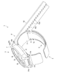
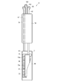
- FIG. 19 is an exploded perspective view showing the configuration of the blood pressure measurement device 1 according to the second embodiment.
- FIG. 20 is a cross-sectional view showing the configuration of the blood pressure measurement device 1 according to the second embodiment.
- the curler 5A is formed in a band shape that curves along the circumferential direction of the wrist.
- the curler 5A is formed such that one end and the other end are separated from each other.
- the curler 5A has a lid 5e that covers the living body-side end of the outer case 31.
- the curler 5A is arranged at a position where one end and the other end project beyond the lid 5e. Further, the curler 5A is separated by a predetermined distance, and one end and the other end are adjacent to each other.
- the lid 5e is fixed to the living body side end of the outer case 31 or the base 33 using a screw 35a or the like.
- the lid 5e is provided on the curler 5A so that one end and the other end of the curler 5A are located on one side of the wrist 200 when the blood pressure measurement device 1 is attached to the wrist 200. Fixed to.
- a notch 5h is formed on the arc-shaped edge of the back surface 5g of the third wing 5f of the lid 5e on the wrist 200 side. Since the notch portion 5h is formed on the back surface 5g, the vicinity of the edge of the back surface 5g is formed as a step.
- the back surface 5g configured in this manner has, for example, the same shape as the surface on the wrist 200 side of the one body of the back cover 35f of the blood pressure measurement device 1 according to the first embodiment and the first facing portion 5a of the curler 5. Composed.
- the surface shape of the third wing portion 5f is not limited to the configuration in which the edge has an arc shape.
- the third blade portion 5f may have a rectangular surface shape, for example.
- the curler 5A has, for example, a shape orthogonal to the circumferential direction of the wrist, that is, curved along the circumferential direction of the wrist 200 in a side view from the longitudinal direction of the wrist 200.
- the curler 5A extends, for example, from the device body 3 to the palm side of the wrist 200 through the back side of the wrist 200 and one side side of the wrist 200, and extends to the other side side of the wrist 200. That is, the curler 5 is arranged along most of the circumferential direction of the wrist 200 by being curved along the circumferential direction of the wrist 200, and both ends thereof are separated by a predetermined distance.
- the curler 5A has hardness having flexibility and shape retention.
- the flexibility means that the shape is deformed in the radial direction when the external force of the belt 4 is applied to the curler 5A.
- “flexibility” means that when the curler 5A is pressed by the belt 4, the curler 5A is close to the wrist, follows the shape of the wrist, or deforms the shape in a side view so as to follow the shape of the wrist.
- the shape-retaining property means that the curler 5A can maintain a preshaped shape when an external force is not applied.
- the outer shape maintaining property means that in the present embodiment, the shape of the curler 5A can be maintained in a shape that curves along the circumferential direction of the wrist.
- the curler 5A has the cuff structure 6 arranged on the inner peripheral surface thereof, and holds the cuff structure 6 along the inner peripheral surface shape of the curler 5.
- the flat cuff 71 and the instep cuff 74 are arranged on the inner peripheral surface, and the flat cuff 71 and the instep cuff 74 are joined by the joining member 8.
- the curler 5A is made of a resin material.
- the curler 5A is formed of, for example, a thermoplastic resin material, specifically, polypropylene.
- the curler 5 is formed to have a thickness of, for example, about 1 mm.
- the curler 5A configured as described above has, for example, a configuration in which the back cover 35 and the facing portion 5a of the blood pressure measurement device 1 according to the first embodiment are integrally formed.
- the surface shape of the second facing portion 107A is, for example, larger than the surface shape of the lid portion 5e.
- the second facing portion 107A has the second wing portion 107a1 extending in the width direction as compared with the portions on both sides of the second facing portion 107A in the longitudinal direction of the eighteenth sheet member 106l.
- the second wing portions 107a are formed one on each side in the width direction of the eighteenth sheet member 106l.
- the second wing portion 107a1 is configured to have a planar shape having an arc-shaped edge having a larger diameter than the arc of the edge of the third wing portion 5f of the lid portion 5e.
- the second opposing portion 107A is joined to the lid portion 5e by being adhered to the lid portion 5e by an adhesive layer 108 made of an adhesive material or a double-sided tape. Since the surface shape of the second facing portion 107A is configured to be larger than the surface shape of the first facing portion 5a, the second wing portion 107a1 is adhered by the adhesive layer 108, so that the lid portion 5e of the lid portion 5e. It is joined to the third wing portion 5f. Further, as an example, the second wing 107a1 is also joined to the cutout portion 5h of the third wing 5f. The region of the second facing portion 107A excluding the second wing portion 107a1 is joined to the region of the lid portion 5e excluding the third wing portion 5f by being adhered by the adhesive layer 108.
- the second wing portion 107a1 has been described as having a configuration in which a part thereof is joined to the cutout portion 5h of the lid portion 5e, but the present invention is not limited to this.
- the second wing portion 107a1 may have a shape that is joined to a region other than the cutout portion 5h on the back surface 5g of the third wing portion 5f on the wrist 200 side.
- the blood pressure measurement device 1 according to the second embodiment configured as described above has the same effects as those of the first embodiment. Furthermore, the number of parts that configure the blood pressure measurement device 1 can be reduced. [Third Embodiment] Next, a third embodiment of the blood pressure measurement device 1 will be described with reference to FIGS. 21 and 22. In the blood pressure measurement device 1 according to the third embodiment, the second blade portion 107a1 of the eighteenth sheet member 106l of the instep cuff 74 is sandwiched between the third blade portion 5f of the lid portion 5e of the curler 5A. The configuration is different from that of the blood pressure measurement device 1 according to the second embodiment described above.
- the same configurations as those of the blood pressure measurement device 1 according to the first embodiment described above will be denoted by the same reference numerals, and the description and Illustration is omitted as appropriate.
- FIG. 21 is a bottom view of the vicinity of one of the two second wing portions 107a1 of the instep cuff 74 as seen from the wrist 200 side.
- 22 is a cross-sectional view showing one of the two second wing portions 107a of the instep cuff 74, which is a cross-sectional view taken along the line XXII-XXII shown in FIG.
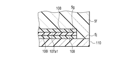
- the blood pressure measurement device 1 further includes two cover members 110 in addition to the configuration of the second embodiment.
- the cover member 110 sandwiches the second wing portion 107a1 with the third wing portion 5f.
- the surface shape of the cover member 110 is configured such that a part of the outer edge is formed in an arc shape and the remaining part is formed in a linear shape.
- the cover member 110 has an arc-shaped edge facing the arc-shaped edge of the lid 5e.
- the diameter of the arc-shaped edge of the cover member 110 is the same as the diameter of the arc-shaped edge of the lid 5e.
- the cover member 110 has an edge portion 111 configured to have an arc-shaped edge.
- the height of the edge portion 111 is higher than that of other portions.
- the edge portion 111 is arranged in the cutout portion 5h of the lid portion 5e. The height mentioned here is the height from the back surface 112 of the cover member 110 on the wrist 200 side.
- the height of the edge portion 111 is such that when the tip of the edge portion 111 is joined to the cutout portion 5h by the adhesive layer 108, the area other than the edge portion 111 of the cover member 110 and the third blade portion of the lid portion 5e.
- the adhesive layer 108 and the second wing portion 107a1 are dimensioned to be sandwiched between the regions other than the cutout portion 5h of 5f.
- the edge portion 111 is bonded to the cutout portion 5h of the lid portion 5e by the adhesive layer 108. Further, on the surface of the cover member 110 on the lid portion 5e side, regions other than the edge portion 111 are bonded to the second wing portion 107a1 by being bonded by the bonding layer 108.
- FIG. 28 is a bottom view of the vicinity of one of the two second wing portions 107a1 of the instep cuff 74 as seen from the wrist 200 side.
- FIG. 29 is a cross-sectional view showing the configuration in the vicinity of one of the two second wing parts 107a1 of the instep cuff 74, and is a cross-sectional view taken along the line XXIV-XXIV shown in FIG.
- the first arc surface portion 5k1 is the largest diameter portion of the side surface 5k.
- the second arc surface portion 5k2 is configured as an arc surface having a curvature center on the same axis as the curvature center of the first arc surface portion 5k1.
- the second arc surface portion 5k2 is configured to have an arc surface having a smaller diameter than the first arc surface portion 5k1.
- the third arc surface portion 5k3 is configured as an arc surface having a curvature center coaxial with the curvature center of the first arc surface portion 5k1.
- the third arc surface portion 5k3 is configured to have an arc surface having a smaller diameter than the second arc surface portion 5k2.
- the cover member 110 is bonded by bonding the edge portion 111 to the region of the second blade portion 107a1 that is bonded to the second back surface portion 5g2 with the bonding layer 108.
- the area other than the edge portion 111 of the cover member 110 is bonded to the area of the second wing portion 107a bonded to the first back surface portion 5b1 by being bonded by the bonding layer 108.
- the outer case 31 has a part of the cover member 110 and the lid 5e fitted therein.
- the fixing strength of the curler 5A and the case 11 and the fixing strength of the cover member 110 and the case 11 are improved. It becomes possible. Furthermore, since the joint between the cover member 110 and the lid 5e is covered by the outer case 31, the sealability at the joint between the cover member 110 and the lid 5e can be improved.
- the joining portion mentioned here is a portion including the line end surface of the edge portion 111, the adhesive layer 108, and the second back surface portion 5g2.
- the second wing portion 107a may be joined to the lid 5e by a joining member.
- the joining member is a member that mechanically joins the two members, and includes, for example, a caulking protrusion, a rivet, and a sewing thread.
- Second on-off valve 17 Pressure sensor 17A ... First pressure sensor 17B ... Second pressure sensor 18 ... Power supply part 19 ... Vibration motor 20 ... Control board 31 ... Outer case 31a ... Lug 31b ... Spring rod 32 ... Windshield 33 ... Base 35 ... Back cover 35a ... Screw 41 ... Button 42 ... Sensor 43 ... Touch panel 51 ... Board 52 ... Acceleration sensor 53 ... Communication section 54 ... Storage section 55 ... Control part 61 ... 1st belt 61a ... 1st hole 61b ... 2nd hole 61c ... Buckle 61d ... Frame-shaped body 61e ... Stick rod 62 ... 2nd belt 62a ... Small hole 62b ...
Landscapes
- Health & Medical Sciences (AREA)
- Life Sciences & Earth Sciences (AREA)
- Cardiology (AREA)
- Surgery (AREA)
- General Health & Medical Sciences (AREA)
- Engineering & Computer Science (AREA)
- Biomedical Technology (AREA)
- Heart & Thoracic Surgery (AREA)
- Medical Informatics (AREA)
- Molecular Biology (AREA)
- Physics & Mathematics (AREA)
- Animal Behavior & Ethology (AREA)
- Pathology (AREA)
- Public Health (AREA)
- Veterinary Medicine (AREA)
- Biophysics (AREA)
- Vascular Medicine (AREA)
- Physiology (AREA)
- Ophthalmology & Optometry (AREA)
- Dentistry (AREA)
- Measuring Pulse, Heart Rate, Blood Pressure Or Blood Flow (AREA)
Abstract
大型化を防止しつつ、カフと接合先との接合強度を向上可能な血圧測定装置を提供すること。 血圧測定装置1は、筒状の外郭ケース31を含むケース11と、手首200の装着する部位の周方向に倣って湾曲し、厚み方向に外郭ケース31の一端に並ぶ第1対向部5aを有するカーラ5と、樹脂材料で形成された二枚のシート部材で形成され、流体により膨張し、カーラ5側に配置されるシート部材の第1対向部5aに対向する第2対向部107が、他の部位よりも幅方向に広い甲カフ74と、を備える。
Description
本発明は、血圧を測定する血圧測定装置に関する。
近年、血圧の測定に用いる血圧測定装置は、医療設備においてのみならず、家庭内においても、健康状態を確認する手段として利用されている。血圧測定装置は、例えば、生体の上腕又は手首等に巻き付けたカフを膨張及び収縮させ、圧力センサによりカフの圧力を検出することで、動脈壁の振動を検出して血圧を測定する。
このような血圧測定装置として、例えば、カフとカフに流体を供給する装置本体とが一体に構成された所謂一体型と呼ばれるものが知られている。このような血圧測定装置は、カフに皺や折れ等が発生すると、測定した血圧測定結果の精度が低下する、という問題がある。また、血圧測定装置は、血管の圧閉方向にカフが膨張し、カフが手首に密着することが求められる。
そこで、血圧測定装置は、膨張したカフを上腕や手首に密着させるために、ベルトとカフの間にカーラを用いる技術が知られている(例えば、日本国特開2018-102743号公報参照)。このような血圧装置は、カーラにカフを、例えば、両面テープ等の接着層により接着して固定させることで、カーラにカフを一体に構成する。
上述した血圧測定装置は、カフ及びカーラの接合強度を向上することが求められている。この為、カフやカーラに設ける接合代を大きくすることで、接合強度を向上することが考えられる。
しかしながら、上述した血圧測定装置は、昨今、手首に装着するウェアラブルデバイスも考えられている。この為、カフやカーラに設ける接合代を大きくすることで、血圧測定装置が大型化することは好ましくない。
そこで本発明は、血圧測定装置の大型化を防止しつつ、カフとカーラの接合強度を向上可能な血圧測定装置を提供することを目的とする。
一態様によれば、筒状の外郭ケースを含むケースと、生体の装着する部位の周方向に倣って湾曲し、厚み方向に前記外郭ケースの一端に並ぶ第1対向部を有するカーラと、樹脂材料で形成された二枚のシート部材で形成され、流体により膨張し、前記カーラ側に配置される前記シート部材の前記第1対向部に対向する第2対向部が、他の部位よりも幅方向に広いカフと、を備える血圧測定装置が提供される。
ここで、流体とは、液体及び空気を含む。
この態様によれば、カフの、幅方向に広い第2対向部をカーラに接合することで接合代が増えるので、カフ及びカーラの接合強度を向上できる。
上記一態様の血圧測定装置において、前第1対向部は、前記カーラの他の部位よりも幅方向に広い形状に構成される、血圧測定装置が提供される。
この態様によれば、カーラにおいて接合面積を増加する第1対向部を、外郭ケースの端部に厚み方向に対向する領域とすることで、接合面積を増加することによる血圧測定装置の大型化を防止できる。すなわち、カーラの第1対向部、及びカフの第2対向部が、外郭ケースに厚み方向に並ぶので、血圧測定装置1の外観が、第1対向部及び第2対向部により大きく変化することがない。このように、血圧測定装置の大型化を防止できる。
上記一態様の血圧測定装置において、前第1対向部は、前記カーラの他の部位よりも幅方向に広い形状に構成される、血圧測定装置が提供される。
この態様によれば、カーラにおいて接合面積を増加する第1対向部を、外郭ケースの端部に厚み方向に対向する領域とすることで、接合面積を増加することによる血圧測定装置の大型化を防止できる。すなわち、カーラの第1対向部、及びカフの第2対向部が、外郭ケースに厚み方向に並ぶので、血圧測定装置1の外観が、第1対向部及び第2対向部により大きく変化することがない。このように、血圧測定装置の大型化を防止できる。
上記一態様の血圧測定装置において、前記第2対向部の、前記他の部位よりも前記幅方向に突出する部分を前記第1対向部との間に狭持するカバー部材を備える、血圧測定装置が提供される。
この構成によれば、カフは、カーラに対する直接接合、及び、カバー部材を介したカーラに対する間接接合により接合される。この為、カフ及びカーラの接合強度を向上できる。
上記一態様の血圧測定装置において、前記カバー部材は、突部を有し、前記第2対向部は、前記突部の一部を配置する孔を有し、前記第1対向部は、前記突部の一部が嵌合する嵌合部を有する、血圧測定装置が提供される。
この態様によれば、カバー部材の突部が、カーラの孔に嵌ることで、カバー部材及びカーラの固定強度が向上するので、カフ及びカーラの接合強度が向上する。
上記一態様の血圧測定装置において、前記ケースは、前記外郭ケースの前記一端を覆う裏蓋を備え、前記第1対向部は、前記裏蓋に接続される、血圧測定装置が提供される。
この態様によれば、ケースの組み立てを、カーラに対して独立して行うことが可能となるので、血圧測定装置の製造の自由度が向上する。
上記一態様の血圧測定装置において、前記第1対向部は、前記外郭ケースの前記一端を覆う、血圧測定装置が提供される。
この態様によれば、カーラが、外郭ケースの裏蓋を兼ねることから、血圧測定装置の部品数を削減できる。
本発明は、カフとカーラの接合強度を向上可能な血圧測定装置を提供することができる。
[第1の実施形態]以下、本発明の第1の実施形態に係る血圧測定装置1の一例について、図1乃至図18を用いて以下例示する。
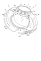
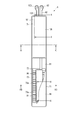
図1は、本発明の第1の実施形態に係る血圧測定装置1の構成を、ベルト4を閉じた状態で示す斜視図である。図2は、血圧測定装置1の構成を、ベルト4を開いた状態で示す斜視図である。図3は、血圧測定装置1の構成を示す分解斜視図である。図4は、血圧測定装置1を手首200に装着した状態を断面で示す説明図である。図5は、血圧測定装置1の構成を示すブロック図である。図6は、血圧測定装置1の装置本体3及びカーラ5の構成を示す斜視図である。図7は、血圧測定装置1のカフ構造体6の構成を示す平面図である。図8は、血圧測定装置1のカフ構造体6の他の構成を示す平面図である。図9は、血圧測定装置1の平カフ71側における、ベルト4、カーラ5及びカフ構造体6の構成を図7中IX-IX線断面で示す断面図である。図10は、血圧測定装置1の甲カフ74側における、カーラ5及びカフ構造体6の構成を示す断面図である。図11は、血圧測定装置1の甲カフ74の第18シート部材106lの構成を示す平面図である。図12は、血圧測定装置1の甲カフ74側における、カーラ5及びチューブ92を省略したカフ構造体6の構成を図7中XII-XII線断面で示す断面図である。図13は、血圧測定装置1を手首200に装着した状態で、カフ構造体6を膨張させたときの構成を示す説明図である。図14は、血圧測定装置1を手首に装着した状態で、カフ構造体6を膨張させたときの構成を図7中XIV-XIV線断面で示す断面図である。
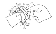
血圧測定装置1は、生体に装着する電子血圧測定装置である。本実施形態においては、生体の手首200に装着するウェアラブルデバイスの態様をもつ電子血圧測定装置を用いて説明する。
図1乃至図3に示すように、血圧測定装置1は、装置本体3と、手首に装置本体3を固定するベルト4と、ベルト4及び手首の間に配置されるカーラ5と、平カフ71、センシングカフ73及び甲カフ74を有するカフ構造体6と、装置本体3及びカフ構造体6を流体的に接続する流体回路7と、カーラ5及びカフ構造体6を接合する接合部材8と、を備えている。
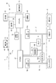
図1乃至図5に示すように、装置本体3は、例えば、ケース11と、表示部12と、操作部13と、ポンプ14と、流路部15と、開閉弁16と、圧力センサ17と、電力供給部18と、振動モータ19と、制御基板20と、を備えている。装置本体3は、ポンプ14、開閉弁16、圧力センサ17及び制御基板20等によって、カフ構造体6に流体を供給する。
図1乃至図3に示すようにケース11は、外郭ケース31と、外郭ケース31の上部開口を覆う風防32と、外郭ケース31の内部の下方に設けられた基部33と、外郭ケース31の下方を覆う裏蓋35と、を備えている。
外郭ケース31は、円筒状に形成される。外郭ケース31は、外周面の周方向で対称位置にそれぞれ設けられた一対のラグ31aと、2つの一対のラグ31a間にそれぞれ設けられるバネ棒31bと、を備えている。風防32は、例えば、円形状のガラス板である。
基部33は、表示部12、操作部13、ポンプ14、開閉弁16、圧力センサ17、電力供給部18、振動モータ19及び制御基板20を保持する。また、基部33は、例えば、ポンプ14及びカフ構造体6を流体的に連続する流路部15の一部を構成する。
裏蓋35は、外郭ケース31の生体側の端部を覆う。裏蓋35は、例えば4つのビス35a等によって外郭ケース31又は基部33の生体側の端部に固定される。裏蓋35の裏面35bの面形状は、外郭ケース31が円筒状に形成されることから、円形状に構成される。また、裏蓋35の径は、外郭ケース31の径よりも小さい。換言すると、裏蓋35の、カーラ5の幅方向に沿う長さは、外郭ケース31の、カーラ5の幅方向に沿う長さよりも短い。
表示部12は、外郭ケース31の基部33上であって、且つ、風防32の直下に配置される。表示部12は、電気的に制御基板20に接続される。表示部12は、例えば、液晶ディスプレイ又は有機エレクトロルミネッセンスディスプレイである。表示部12は、日時や最高血圧及び最低血圧などの血圧値や心拍数等の測定結果を含む各種情報を表示する。
操作部13は、使用者からの指令を入力可能に構成される。例えば、操作部13は、図5に示すように、ケース11に設けられた複数の釦41と、釦41の操作を検出するセンサ42と、表示部12又は風防32に設けられたタッチパネル43と、を備える。操作部13は、使用者が操作することで、指令を電気信号に変換する。センサ42及びタッチパネル43は、電気的に制御基板20に接続され、電気信号を制御基板20へ出力する。
複数の釦41は、例えば3つ設けられる。釦41は、基部33に支持されるとともに、外郭ケース31の外周面から突出する。複数の釦41及び複数のセンサ42は、基部33に支持される。タッチパネル43は、例えば、風防32に一体に設けられる。
ポンプ14は、例えば圧電ポンプである。ポンプ14は、空気を圧縮し、流路部15を介して圧縮空気をカフ構造体6に供給する。ポンプ14は、電気的に制御基板20に接続される。
流路部15は、図5に示すように、ポンプ14から平カフ71及び甲カフ74へつながる流路、及び、ポンプ14からセンシングカフ73へつながる流路を構成する。また、流路部15は、平カフ71及び甲カフ74から大気へつながる流路、及び、センシングカフ73から大気へつながる流路を構成する。流路部15は、基部33等に設けられた中空部、溝及びチューブ等により構成された空気の流路である。
開閉弁16は、流路部15の一部を開閉する。開閉弁16は、例えば、図5に示すように、複数設けられ、各開閉弁16の開閉の組み合わせによりポンプ14から平カフ71及び甲カフ74へつながる流路、ポンプ14からセンシングカフ73へつながる流路、平カフ71及び甲カフ74から大気へつながる流路、及び、センシングカフ73から大気へつながる流路を選択的に開閉する。例えば、開閉弁16は、2つ用いられる。
圧力センサ17は、平カフ71、センシングカフ73及び甲カフ74の圧力を検出する。圧力センサ17は、電気的に制御基板20に接続される。圧力センサ17は、検出した圧力を電気信号に変換し、制御基板20へ出力する。圧力センサ17は、例えば、図5に示すように、ポンプ14から平カフ71及び甲カフ74へつながる流路、及び、ポンプ14からセンシングカフ73へつながる流路に設けられる。これらの流路は平カフ71、センシングカフ73及び甲カフ74と連続することから、これら流路内の圧力が平カフ71、センシングカフ73及び甲カフ74の内部空間の圧力となる。
電力供給部18は、例えば、リチウムイオンバッテリ等の二次電池である。電力供給部18は、制御基板20に電気的に接続される。電力供給部18は、制御基板20に電力を供給する。
図5及び図6に示すように、制御基板20は、例えば、基板51と、加速度センサ52と、通信部53と、記憶部54と、制御部55と、を備えている。制御基板20は、加速度センサ52、通信部53、記憶部54及び制御部55が基板51に実装されることで構成される。
基板51は、ケース11の基部33にビス等によって固定される。
加速度センサ52は、例えば、3軸加速度センサである。加速度センサ52は、装置本体3の互いに直交する3方向の加速度を表す加速度信号を制御部55に出力する。例えば、加速度センサ52は、検出された加速度から血圧測定装置1を装着した生体の活動量を測定するために用いられる。
通信部53は、外部の装置と無線又は有線によって情報を送受信可能に構成される。通信部53は、例えば、制御部55によって制御された情報や測定された血圧値及び脈拍等の情報を、ネットワークを介して外部の装置へ送信し、また、外部の装置からネットワークを介してソフトウェア更新用のプログラム等を受信して制御部に送る。
本実施形態において、ネットワークは、例えばインターネットであるが、これに限定されず、病院内に設けられたLAN(Local Area Network)等のネットワークであってもよく、また、USB等の所定の規格の端子を有するケーブルなどを用いた外部の装置との直接的な通信であってもよい。このため、通信部53は、無線アンテナ及びマイクロUSBコネクタ等の複数を含む構成であってもよい。
記憶部54は、血圧測定装置1全体及び流体回路7を制御するためのプログラムデータ、血圧測定装置1の各種機能を設定するための設定データ、圧力センサ17で測定された圧力から血圧値や脈拍を算出するための算出データ等を予め記憶する。また、記憶部54は、測定された血圧値や脈拍等の情報を記憶する。
制御部55は、単数又は複数のCPUにより構成され、血圧測定装置1全体の動作、及び、流体回路7の動作を制御する。制御部55は、表示部12、操作部13、ポンプ14、各開閉弁16及び各圧力センサ17に電気的に接続されるとともに、電力を供給する。また、制御部55は、操作部13及び圧力センサ17が出力する電気信号に基づいて、表示部12、ポンプ14及び開閉弁16の動作を制御する。
例えば、制御部55は、図5に示すように、血圧測定装置1全体の動作を制御するメインCPU(Central Processing Unit)56及び流体回路7の動作を制御するサブCPU57を有する。例えば、メインCPU56は、圧力センサ17が出力する電気信号から、最高血圧及び最低血圧などの血圧値や心拍数などの測定結果を求め、この測定結果に対応した画像信号を表示部12へ出力する。
例えば、サブCPU57は、操作部13から血圧を測定する指令が入力されると、ポンプ14及び開閉弁16を駆動して平カフ71及びセンシングカフ73に圧縮空気を送る。また、サブCPU57は、圧力センサ17が出力する電気信号に基づいて、ポンプ14の駆動及び停止、並びに、開閉弁16の開閉を制御する。サブCPU57は、ポンプ14及び開閉弁16を制御することで、圧縮空気を平カフ71及びセンシングカフ73に選択的に送るとともに、平カフ71及びセンシングカフ73を選択的に減圧する。
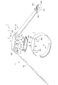
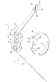
図1乃至図3に示すように、ベルト4は、一方の一対のラグ31a及びバネ棒31bに設けられた第1ベルト61と、他方の一対のラグ31a及びバネ棒31bに設けられた第2ベルト62と、を備える。ベルト4は、カーラ5を介して手首200に巻き付けられる。
第1ベルト61は、所謂親と呼ばれ、帯状に構成される。第1ベルト61は、一方の端部に設けられ、第1ベルト61の長手方向に直交する第1孔部61aと、他方の端部に設けられ、第1ベルト61の長手方向に直交する第2孔部61bと、第2孔部61bに設けられた尾錠61cと、を有する。第1孔部61aは、バネ棒31bを挿入可能、且つ、バネ棒31bに関して第1ベルト61が回転可能な内径を有する。即ち、第1ベルト61は、一対のラグ31aの間であって、且つ、バネ棒31bに第1孔部61aが配置されることで、外郭ケース31に回転可能に保持される。
第2孔部61bは、第1ベルト61の先端に設けられる。尾錠61cは、矩形枠状の枠状体61dと、枠状体61dに回転可能に取り付けられたつく棒61eと、を有する。枠状体61dは、つく棒61eが取り付けられた一辺が第2孔部61bに挿入され、第1ベルト61に関して回転可能に取り付けられる。
第2ベルト62は、所謂剣先と呼ばれ、枠状体61dに挿入可能な幅を有する帯状に構成される。また、第2ベルト62は、つく棒61eが挿入される小孔62aを複数有する。また、第2ベルト62は、一方の端部に設けられ、第2ベルト62の長手方向に直交する第3孔部62bを有する。第3孔部62bは、バネ棒31bを挿入可能、且つ、バネ棒31bに関して第2ベルト62が回転可能な内径を有する。即ち、第2ベルト62は、一対のラグ31aの間であって、且つ、バネ棒31bに第3孔部62bが配置されることで、外郭ケース31に回転可能に保持される。
このようなベルト4は、第2ベルト62が枠状体61dに挿入され、小孔62aにつく棒61eが挿入されることで、第1ベルト61及び第2ベルト62が一体に接続され、外郭ケース31とともに、手首200の周方向に倣った環状となる。
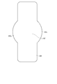
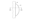
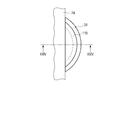
カーラ5は、図4に示すように、手首の周方向に沿って湾曲する帯状に構成される。カーラ5は、一端と他端が離間して形成される。カーラ5は、例えば、一端側の外面が装置本体3の裏蓋35に固定される。カーラ5は、一端及び他端が裏蓋35よりも突出した位置に配置される。また、カーラ5は、所定の距離だけ離間して一端及び他端が隣接する。
また、カーラ5は、血圧測定装置1を手首200に装着したときに、一端及び他端が手首200の一方の側方へ位置するように、裏蓋35に固定される。
具体例として、図3に示すように、カーラ5は、第1対向部5aを有する。第1対向部5aは、裏蓋35に対向する。換言すると、第1対向部5aは、外郭ケース31の軸方向に、外郭ケースの端部に並ぶ。
第1対向部5aは、ビス35a等を用いて裏蓋35に固定される。なお、カーラ5は、一例としてビス35a等を用いて裏蓋35と共に、外郭ケース31又は基部33の生体側の端部に固定される。なお、裏蓋35は、ビス35aにより、裏蓋35と共に外郭ケース31または基部33の生体側の端部に固定される構成を説明したが、これに限定されない。裏蓋35は、他の例では、接着剤や両面テープ等により構成される接着層により、裏蓋35の裏面35bに固定されてもよい。なお、裏面35bは、手首200側の面である。
第1対向部5aは、カーラ5の第1対向部5a以外の部位に比較して幅が広い形状に構成される。第1対向部5aの面形状は、一例として、裏蓋35の裏面35bの面形状より小さく構成される。すなわち、第1対向部5aの面形状は、円形状に構成される裏面35bの面形状より、小さい円形状の円形状に構成される。
第1対向部5aは、具体例として、カーラ5の幅方向の両側のそれぞれに、カーラ5の長手方向で第1対向部5aの両側の部分に比較して幅方向に突出する第1羽部5bを有する。第1羽部5bのそれぞれは、縁部が幅方向外側に突出する円弧状に形成される形状に構成される。このように、第1対向部5aは、2つの第1羽部5bを有することから、カーラ5の長手方向で第1対向部5aの両側の部分に比較して、幅方向に広い形状に構成される。
具体例として、図1及び図2、図4に示すように、カーラ5は、例えば、手首の周方向に対して直交する方向、換言すると手首200の長手方向からの側面視で手首200の周方向に沿って湾曲する形状を有する。カーラ5は、例えば、装置本体3から手首200の手の甲側及び手首200の一方の側方側を通って手首200の手の平側へと渡り、手首200の他方の側方側へと延びる。即ち、カーラ5は、手首200の周方向に沿って湾曲することで、手首200の周方向の大半に渡って配置されるとともに、両端が所定の間隔を有して離間する。
カーラ5は、可撓性及び形状保持性を有する硬さを有する。ここで、可撓性とは、カーラ5にベルト4の外力が印加されたときに径方向に形状が変形することをいう。例えば、可撓性とは、ベルト4によってカーラ5が押圧されたときに、手首に近接するか、手首の形状に沿うか、又は、手首の形状に倣うように側面視の形状が変形することをいう。また、形状保持性とは、外力が印加されないときに、カーラ5が予め賦形された形状を維持できることをいう。例えば、外形保持性とは、本実施形態においてはカーラ5の形状が手首の周方向に沿って湾曲する形状を維持できることである。
カーラ5は、内周面にカフ構造体6が配置され、そして、カーラ5の内周面形状に沿ってカフ構造体6を保持する。具体例として、カーラ5は、平カフ71及び甲カフ74が内周面に配置され、接合部材8により、平カフ71及び甲カフ74が接合される。
カーラ5は、樹脂材料で形成される。カーラ5は、例えば、熱可塑性樹脂材料、具体例として、ポリプロピレンによって形成される。カーラ5は、例えば、厚さが1mm程度に形成される。
図1乃至図4、図7乃至図14に示すように、カフ構造体6は、平カフ(カフ)71と、背板72と、センシングカフ73と、甲カフ(カフ)74と、を備えている。カフ構造体6は、カーラ5に固定される。カフ構造体6は、平カフ71、背板72及びセンシングカフ73が積層してカーラ5に配置され、甲カフ74が平カフ71、背板72及びセンシングカフ73と離間してカーラ5に配置される。
具体例として、カフ構造体6は、カーラ5の内面に、平カフ71、背板72、センシングカフ73及び甲カフ74が配置される。カフ構造体6は、カーラ5の手首200の手の平側の内面に、カーラ5の内面から生体側に向かって、平カフ71、背板72及びセンシングカフ73の順に積層して固定される。また、カフ構造体6は、カーラ5の手首200の手の甲側の内面に甲カフ74が配置される。カフ構造体6の各部材は、積層方向に隣接する部材に両面テープや接着剤等によって固定される。
平カフ71は、所謂押圧カフである。平カフ71は、流路部15を介してポンプ14に流体的に接続される。平カフ71は、膨張することで背板72及びセンシングカフ73を生体側に押圧する。平カフ71は、複数の、例えば二層の空気袋81と、二層の空気袋81のうちカーラ5側に配置される空気袋81に設けられる複数の挿入孔82と、を含む。
ここで、空気袋81とは、袋状構造体であり、本実施形態においては血圧測定装置1がポンプ14により空気を用いる構成であることから、空気袋を用いて説明するが、空気以外の流体を用いる場合には、袋状構造体は液体袋等の流体袋であってもよい。複数の空気袋81は、積層され、積層方向に流体的に連通する。
空気袋81は、一方向に長い矩形状に構成される。空気袋81は、例えば、一方向に長い二枚のシート部材86を組み合わせ、縁部を熱により溶着することで構成される。即ち、空気袋81は、四辺の周縁部が溶着された溶着部81aを有する。
具体例として、二層の空気袋81は、図7及び図9に示すように、生体側から、第1シート部材86aと、第1シート部材86aと一層目の空気袋81を構成する第2シート部材86bと、第2シート部材86bと一体に接着される第3シート部材86cと、第3シート部材86cと二層目の空気袋81を構成する第4シート部材86dと、を備える。なお、二層の空気袋81は、隣り合う空気袋81の各シート部材86が両面テープ、接着剤等による接着又は溶着等により接合されることで一体に構成される。
第1シート部材86a及び第2シート部材86bは、四辺の周縁部が溶着されることで空気袋81を構成する。第2シート部材86b及び第3シート部材86cは、対向して配置され、それぞれ、二つの空気袋81を流体的に連続させる複数の開口86b1、86c1を有する。
第3シート部材86c及び第4シート部材86dは、四辺の周縁部が溶着されることで空気袋81を構成する。
背板72は、接着剤層や両面テープ等により平カフ71の第1シート部材86aの外面に貼付される。背板72は、樹脂材料で板状に形成される。背板72は、例えば、ポリプロピレンからなり、厚さが1mm程度の板状に形成される。背板72は、形状追従性を有する。
ここで、形状追従性とは、配置される手首200の被接触箇所の形状を倣うように背板72が変形可能な機能をいい、手首200の被接触箇所とは、背板72が対向する手首200の領域をいい、ここでの接触とは、直接的な接触及びセンシングカフ73を介した間接的な接触の双方を含む。
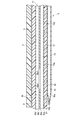
例えば、図9に示すように、背板72は、背板72の両主面に長手方向に対して直交する方向に延びる複数の溝72aを有する。図9に示すように、溝72aは、背板72の両主面にそれぞれ複数設けられる。両主面に設けられた複数の溝72aは、背板72の厚さ方向においてそれぞれ対向する。また、複数の溝72aは、背板72の長手方向に等間隔に配置される。
背板72は、複数の溝72aを有する部位が溝72aを有さない部位に比べて薄肉となることで、複数の溝72aを有する部位が変形しやすいことから、手首200の形状に倣って変形し、手首の周方向に延在する形状追従性を有する。背板72は、手首200の手の平側を覆う長さに形成される。背板72は、手首200の形状に沿った状態で、平カフ71からの押圧力をセンシングカフ73の背板72側の主面に伝達する。
センシングカフ73は、背板72の生体側の主面に固定される。センシングカフ73は、図9及び図14に示すように、手首200の動脈210が存する領域に直接接触する。ここで、動脈210とは、橈骨動脈及び尺骨動脈である。センシングカフ73は、背板72の長手方向及び幅方向で、背板72と同一形状か、又は、背板72よりも小さい形状に形成される。センシングカフ73は、膨張することで手首200の手の平側の動脈210が存する領域を圧迫する。センシングカフ73は、膨張した平カフ71により、背板72を介して生体側に押圧される。
具体例として、センシングカフ73は、一つの空気袋91と、空気袋91と連通するチューブ92と、チューブ92の先端に設けられた接続部93と、を含む。センシングカフ73は、空気袋91の一方の主面が背板72に固定される。例えば、センシングカフ73は、背板72の生体側の主面に両面テープや接着剤層等により貼付される。
ここで、空気袋91とは、袋状構造体であり、本実施形態においては血圧測定装置1がポンプ14により空気を用いる構成であることから、空気袋を用いて説明するが、空気以外の流体を用いる場合には、袋状構造体は液体袋等であってもよい。
空気袋91は、一方向に長い矩形状に構成される。空気袋91は、例えば、一方向に長い二枚のシート部材96を組み合わせ、縁部を熱により溶着することで構成される。具体例として、空気袋91は、図14に示すように、生体側から第5シート部材96a及び第6シート部材96bを備える。
例えば、第5シート部材96a及び第6シート部材96bは、第5シート部材96a及び第6シート部材96bの一辺に、空気袋91の内部空間と流体的に連続するチューブ92が配置され、溶着により固定される。例えば、第5シート部材96a及び第6シート部材96bは、第5シート部材96a及び第6シート部材96b間にチューブ92が配置された状態で四辺の周縁部を溶着して空気袋91を成形することで、チューブ92が一体に溶着される。
チューブ92は、空気袋91の長手方向の一方の端部に設けられる。具体例として、チューブ92は、空気袋91の装置本体3に近い端部に設けられる。チューブ92は、先端に、接続部93を有する。チューブ92は、流路部15に接続され、装置本体3と空気袋91との間の流路を構成する。接続部93は、流路部15に接続される。接続部93は、例えばニップルである。
甲カフ74は、所謂引っ張りカフである。甲カフ74は、流路部15を介してポンプ14に流体的に接続される。甲カフ74は、膨張することで手首200から離間するようにカーラ5を押圧することで、ベルト4及びカーラ5を手首200の手の甲側に引っ張る。甲カフ74は、複数の、例えば六層の空気袋101と、空気袋101と連通するチューブ102と、チューブ102の先端に設けられた接続部103と、を含む。
また、甲カフ74は、膨張方向、本実施形態においては、カーラ5及び手首200の対向する方向で、膨張時の厚さが、平カフ71の膨張方向における膨張時の厚さ、及び、センシングカフ73の膨張方向における膨張時の厚さよりも厚く構成される。即ち、甲カフ74の空気袋101は、平カフ71の空気袋81及びセンシングカフ73の空気袋91よりも多い層構造を有し、カーラ5から手首200に向かって膨張したときの厚さが平カフ71及びセンシングカフ73よりも厚い。
ここで、空気袋101とは、袋状構造体であり、本実施形態においては血圧測定装置1がポンプ14により空気を用いる構成であることから、空気袋を用いて説明するが、空気以外の流体を用いる場合には、袋状構造体は液体袋等の流体袋であってもよい。複数の空気袋101は、積層され、積層方向に流体的に連通する。
空気袋101は、一方向に長い矩形状に構成される。空気袋101は、例えば、一方向に長い二枚のシート部材106を組み合わせ、縁部を熱により溶着することで構成される。即ち、空気袋101は、四辺の周縁部が溶着された溶着部101aを有する。
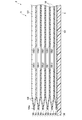
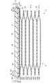
具体例として、六層の空気袋101は、図10に示すように、生体側から、第7シート部材106aと、第8シート部材106bと、第9シート部材106cと、第10シート部材106dと、第11シート部材106eと、第12シート部材106fと、第13シート部材106gと、第14シート部材106hと、第15シート部材106iと、第16シート部材106jと、第17シート部材106kと、第18シート部材106lと、を備えている。なお、六層の空気袋101は、隣り合う空気袋101の各シート部材106が両面テープ、接着剤等による接着又は溶着等により接合されることで一体に構成される。
第7シート部材106a及び第8シート部材106bは、四辺の周縁部が溶着されることで、一層目の空気袋101を構成する。第8シート部材106b及び第9シート部材106cは、対向して配置され、一体に接着される。第8シート部材106b及び第9シート部材106cは、隣り合う空気袋101を流体的に連続させる複数の開口106b1、106c1を有する。第9シート部材106c及び第10シート部材106dは、四辺の周縁部が溶着されることで、二層目の空気袋101を構成する。
第10シート部材106d及び第11シート部材106eは、対向して配置され、一体に接着される。第10シート部材106d及び第11シート部材106eは、隣り合う空気袋101を流体的に連続させる複数の開口106d1、106e1を有する。第11シート部材106e及び第12シート部材106fは、四辺の周縁部が溶着されることで、三層目の空気袋101を構成する。
第12シート部材106f及び第13シート部材106gは、対向して配置され、一体に接着される。第12シート部材106f及び第13シート部材106gは、隣り合う空気袋101を流体的に連続させる複数の開口106f1、106g1を有する。第13シート部材106g及び第14シート部材106hは、四辺の周縁部が溶着されることで、四層目の空気袋101を構成する。
第14シート部材106h及び第15シート部材106iは、対向して配置され、一体に接着される。第14シート部材106h及び第15シート部材106iは、隣り合う空気袋101を流体的に連続させる複数の開口106h1、106i1を有する。第15シート部材106i及び第16シート部材106jは、四辺の周縁部が溶着されることで、五層目の空気袋101を構成する。
第16シート部材106j及び第17シート部材106kは、対向して配置され、一体に接着される。第16シート部材106j及び第17シート部材106kは、隣り合う空気袋101を流体的に連続させる複数の開口106j1、106k1を有する。第17シート部材106k及び第18シート部材106lは、矩形枠状に周縁部が溶着されることで、六層目の空気袋101を構成する。第18シート部材106lは、カーラ5側に配置される。
また、例えば、第17シート部材106k及び第18シート部材106lの一辺に、空気袋101の内部空間と流体的に連続するチューブ102が配置され、溶着により固定される。例えば、第17シート部材106k及び第18シート部材106lは、第17シート部材106k及び第18シート部材106lの間にチューブ102が配置された状態で矩形枠状に周縁部を溶着して空気袋101を成形することで、チューブ102が一体に溶着される。
例えば、このような六層目の空気袋101は、平カフ71の二層目の空気袋81と一体に構成される。即ち、第17シート部材106kは、第3シート部材86cと一体に構成され、第18シート部材106lは、第4シート部材86dと一体に構成される。
より詳細に述べると、第3シート部材86c及び第17シート部材106kは、一方向に長い矩形状のシート部材を構成し、第18シート部材106l及び第4シート部材86dは、一方向に長い矩形状のシート部材を構成する。そして、これらシート部材を重ね合わせて、一方の端部側を矩形枠状であって、且つ、他方の端部側の一辺の一部を除いて溶着する。これにより、平カフ71の二層目の空気袋81が構成される。そして、他方の端部側を矩形枠状であって、且つ、一方の端部側の一辺の一部を除いて溶着することで、甲カフ74の六層目の空気袋101が構成される。また、二層目の空気袋81及び六層目の空気袋101は、それぞれ対向する側の一辺の一部が溶着されないことから、流体的に連続する。
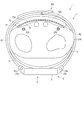
また、図11及び図12に示すように、第18シート部材106lは、カーラ5の第1対向部5aに接合される第2対向部107を有する。
第2対向部107は、第18シート部材106lの、第1対向部5aに対向する部分であり、第18シート部材106lの、第1対向部5aに対向しない部位に比較して、幅方向に広い形状に構成される。
さらに、第2対向部107の面形状は、第1対向部5aの面形状より、大きい形状に構成される。具体例として、第2対向部107は、第18シート部材106lの長手方向で第2対向部107の両側の部分に比較して、幅方向に延出する第2羽部107aを有する。
第2羽部107aは、第18シート部材106lの幅方向で両側に1つずつ形成される。第2羽部107aは、一例として、第1対向部5aの第1羽部5bの円弧状の縁よりも大径の円弧状の縁を有する形状に構成される。
第2対向部107は、第1対向部5aに、接着材や両面テープ等により構成される接着層108により、接着されることで接合される。第2羽部107aの面形状が、第1羽部5bの面形状よりも大きい形状に構成されることから、第2羽部107aは、接着層108により接着されることで、第1羽部5bの裏面5c、第1羽部5bの側面5d、及び裏蓋35の裏面35bに接合される。第2対向部107の第2羽部107aを除いた領域は、第1対向部5aの第1羽部5bを除いた領域に、接着層108により接着されることで接合される。
なお、第2羽部107aは、その一部が裏蓋35の裏面35bに接合される構成を説明したが、これに限定されない。他の例では、第2羽部107aは、第1対向部5aのみに接合される構成であってもよい。
チューブ102は、六層の空気袋101のうち一つの空気袋101に接続されるとともに、空気袋101の長手方向の一方の端部に設けられる。具体例として、チューブ102は、六層の空気袋101のカーラ5側であって、且つ、装置本体3に近い端部に設けられる。チューブ102は、先端に、接続部103を有する。チューブ102は、流体回路7のうち、装置本体3と空気袋101との間の流路を構成する。接続部103は、例えばニップルである。
なお、これらの説明のように、本実施形態において、甲カフ74は、一部が平カフ71と一体に構成され、平カフ71と流体的に連続する構成を説明したが、これに限定されず、例えば、図8に示すように、甲カフ74は、平カフ71と別体に構成され、平カフ71と流体的に非連続であってもよい。このような構成とする場合には、平カフ71は、センシングカフ73及び甲カフ74と同様に、さらにチューブ、接続部を設け、また、流体回路7においても、平カフ71へ流体を供給する流路、逆止弁及び圧力センサを接続する構成とすればよい。
また、平カフ71、センシングカフ73及び甲カフ74を形成する各シート部材86、96、106は、熱可塑性樹脂材料により形成される。熱可塑性樹脂材料は、熱可塑性エラストマーである。シート部材86、96、106を構成する熱可塑性樹脂材料としては、例えば、熱可塑性ポリウレタン系樹脂(Thermoplastic PolyUrethane、以下TPUと表記する)、塩化ビニル樹脂(PolyVinyl Chloride)、エチレン酢酸ビニル樹脂(Ethylene-Vinyl Acetate)、熱可塑性ポリスチレン系樹脂(Thermoplastic PolyStyrene)、熱可塑性ポリオレフィン樹脂(Thermoplastic PolyOlefin)、熱可塑性ポリエステル系樹脂(ThermoPlastic Polyester)及び熱可塑性ポリアミド樹脂(Thermoplastic PolyAmide)を用いることができる。
例えば、シート部材86、96、106は、Tダイ押し出し成形や射出成形等の成形方式が用いられる。シート部材86、96、106は、各成形方式で成形された後、所定の形状にサイジングされ、そして、サイジングした個片を溶着等により接合することで袋状構造体81、91、101を構成する。溶着の方式としては、高周波ウェルダーやレーザー溶着が用いられる。
流体回路7は、ケース11、ポンプ14、流路部15、開閉弁16、圧力センサ17、平カフ71、センシングカフ73、及び、甲カフ74によって構成される。流体回路7に用いられる二つの開閉弁16を第1開閉弁16A及び第2開閉弁16Bとし、二つの圧力センサ17を第1圧力センサ17A及び第2圧力センサ17Bとして、以下、流体回路7の具体例を説明する。
流体回路7は、図5に示すように、例えば、ポンプ14から平カフ71及び甲カフ74を連続する第1流路7aと、第1流路7aの中途部が分岐されることで構成され、ポンプ14からセンシングカフ73を連続する第2流路7bと、第1流路7aと大気を接続する第3流路7cと、を備えている。また、第1流路7aは、第1圧力センサ17Aを含む。第1流路7a及び第2流路7bの間には第1開閉弁16Aが設けられる。第2流路7bは、第2圧力センサ17Bを含む。第1流路7a及び第3流路7cの間には、第2開閉弁16Bが設けられる。
このような流体回路7は、第1開閉弁16A及び第2開閉弁16Bが閉じることで、第1流路7aのみがポンプ14と接続し、ポンプ14及び平カフ71が流体的に接続される。流体回路7は、第1開閉弁16Aが開き、そして、第2開閉弁16Bが閉じることで、第1流路7a及び第2流路7bが接続され、ポンプ14及び甲カフ74、甲カフ74及び平カフ71、並びに、ポンプ14及びセンシングカフ73が流体的に接続される。流体回路7は、第1開閉弁16Aが閉じ、そして、第2開閉弁16Bが閉じることで、第1流路7a及び第3流路7cが接続され、平カフ71、甲カフ74及び大気が流体的に接続される。流体回路7は、第1開閉弁16A及び第2開閉弁16Bが開くことで、第1流路7a、第2流路7b及び第3流路7cが接続され、平カフ71、センシングカフ73、甲カフ74及び大気が流体的に接続される。
次に、血圧測定装置1を使用した血圧値の測定の一例について、図15乃至図18を用いて説明する。図15は、血圧測定装置1を用いた血圧測定の一例を示す流れ図であり、ユーザの動作及び制御部55の動作の双方を示す。また、図16乃至図18は、ユーザが手首200に血圧測定装置1を装着する一例を示す。
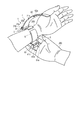
先ず、ユーザは、手首200に血圧測定装置1を装着する(ステップST1)。具体例として、例えば、ユーザは、図26に示すように、手首200の一方をカーラ5内に挿入する。
このとき、血圧測定装置1は、装置本体3及びセンシングカフ73がカーラ5の相対する位置に配置されることから、センシングカフ73を手首200の手の平側の動脈210が存する領域に配置される。これにより、装置本体3及び甲カフ74は、手首200の手の甲側に配される。次いで図17に示すように、ユーザが血圧測定装置1を配した手とは反対の手によって、第1ベルト61の尾錠61cの枠状体61dに第2ベルト62を通す。次いで、ユーザは、第2ベルト62を引っ張り、カーラ5の内周面側の部材、即ち、カフ構造体6を手首200に密着させ、小孔62aにつく棒61eを挿入する。これにより、図18に示すように、第1ベルト61及び第2ベルト62が接続され、血圧測定装置1が手首200に装着される。
次に、ユーザは、操作部13を操作して、血圧値の測定開始に対応した指令の入力を行う。指令の入力操作が行われた操作部13は、測定開始に対応した電気信号を制御部55へ出力する(ステップST2)。制御部55は、当該電気信号を受信すると、例えば、第1開閉弁16Aを開くとともに、第2開閉弁16Bを閉じ、ポンプ14を駆動し、第1流路7a及び第2流路7bを介して平カフ71、センシングカフ73及び甲カフ74へ圧縮空気を供給する(ステップST3)。これにより、平カフ71、センシングカフ73及び甲カフ74は膨張を開始する。
第1圧力センサ17A及び第2圧力センサ17Bは、平カフ71、センシングカフ73及び甲カフ74の圧力をそれぞれ検出し、この圧力に対応した電気信号を制御部55へ出力する(ステップST4)。制御部55は、受信した電気信号に基づいて、平カフ71、センシングカフ73及び甲カフ74の内部空間の圧力が血圧測定のための所定の圧力に達しているか否かを判断する(ステップST5)。例えば、平カフ71及び甲カフ74の内圧が所定の圧力に達しておらず、且つ、センシングカフ73の内圧が所定の圧力に達した場合には、制御部55は、第1開閉弁16Aを閉じ、第1流路7aを介して圧縮空気を供給する。
平カフ71及び甲カフ74の内圧並びにセンシングカフ73の内圧が、全て所定の圧力に達した場合には、制御部55は、ポンプ14の駆動を停止する(ステップST5でYES)。このとき、図13及び図14に示すように、平カフ71及び甲カフ74は十分に膨張しており、膨張した平カフ71は、背板72を押圧する。また、甲カフ74は、手首200から離間する方向に、カーラ5を押圧することから、ベルト4、カーラ5及び装置本体3は、手首200から離間する方向に移動し、結果、平カフ71、背板72、センシングカフ73及びフラット板75が手首200側に引っ張られる。加えて、甲カフ74の膨張によってベルト4、カーラ5及び装置本体3が手首200から離間する方向に移動するときに、ベルト4及びカーラ5が、手首200の両側方に向かって移動し、手首200の両側方に密着した状態で、ベルト4、カーラ5及び装置本体3が移動する。このため、手首200の皮膚に密着したベルト4及びカーラ5は、手首200の両側方の皮膚を手の甲側に引っ張る。
さらに、センシングカフ73は、内圧が血圧を測定するために要する圧力となるように所定の空気量が供給され、膨張しており、そして、平カフ71に押圧された背板72によって手首200に向かって押圧される。このため、センシングカフ73は、手首200内の動脈210を押圧し、図14に示すように動脈210を閉塞する。
また、制御部55は、例えば、第2開閉弁16Bを制御し、第2開閉弁16Bの開閉を繰り返すか、又は、第2開閉弁16Bの開度を調整することで、平カフ71の内部空間の圧力を加圧させる。この加圧の過程において第2圧力センサ17Bが出力する電気信号に基づいて、制御部55は、最高血圧及び最低血圧等の血圧値や心拍数等の測定結果を求める(ステップST6)。制御部55は、求めた測定結果に対応した画像信号を、表示部12へ出力し、測定結果を表示部12に表示する(ステップST7)。また、制御部55は、血圧測定終了後、第1開閉弁16A及び第2開閉弁16Bを開く。
表示部12は、画像信号を受信すると、当該測定結果を画面に表示する。使用者は、表示部12を視認することで、当該測定結果を確認する。なお、使用者は、測定終了後、小孔62aからつく棒61eを外し、枠状体61dから第2ベルト62を外し、カーラ5から手首200を抜くことで、手首200から血圧測定装置1を取り外す。
このように構成された第1の実施形態に係る血圧測定装置1は、カーラ5の第1対向部5aが第1羽部5bを有し、甲カフ74のカーラ5側に配される第18シート部材106lの第2対向部107が、第2羽部107aを有する。そして、第2羽部107aは、接着層108により第1羽部5bに接着されることで、接合される。このように、羽部5a1,107aにより、甲カフ74及びカーラ5を接合する接合面積が増加する。この為、血圧測定装置1は、甲カフ74及びカーラ5の接合強度を向上できる。さらに、第1羽部5b及び第2羽部107を用いることで、カーラ5及び甲カフ74の一部のみ接合代を増加する構成となるので、血圧測定装置1の大型化を防止できる。
さらに、第2対向部107の面形状が第1対向部5aの面形状よりも広い形状に形成され、第2羽部107aの一部が裏蓋35にも固定される構成を採用することで、甲カフ74を直接ケース11に接合できるので、甲カフ74のケース11に対する固定強度を向上できる。
上述したように本実施形態に係る血圧測定装置1によれば、甲カフ74及びカーラ5の接合強度を向上することが可能となる。
[第2の実施形態]
次に、血圧測定装置1の第2の実施形態について、図19及び図20を用いて説明する。なお、第2の実施形態に係る血圧測定装置1は、カーラ5及び裏蓋35が一体に形成される構成であり、この点で、上述した第1の実施形態に係る血圧測定装置1と異なる。この為、第2の実施形態の血圧測定装置1の構成のうち、上述した第1の実施形態に係る血圧測定装置1と同様の構成については同一符号を付して説明するとともに、その説明及び図示を適宜省略する。なお、第2の実施形態において、カーラ5及び裏蓋35が一体に形成された形状を有するカーラを、カーラ5Aと称する。
[第2の実施形態]
次に、血圧測定装置1の第2の実施形態について、図19及び図20を用いて説明する。なお、第2の実施形態に係る血圧測定装置1は、カーラ5及び裏蓋35が一体に形成される構成であり、この点で、上述した第1の実施形態に係る血圧測定装置1と異なる。この為、第2の実施形態の血圧測定装置1の構成のうち、上述した第1の実施形態に係る血圧測定装置1と同様の構成については同一符号を付して説明するとともに、その説明及び図示を適宜省略する。なお、第2の実施形態において、カーラ5及び裏蓋35が一体に形成された形状を有するカーラを、カーラ5Aと称する。
図19は、第2の実施形態に係る血圧測定装置1の構成を分解して示す斜視図である。図20は、第2の実施形態に係る血圧測定装置1の構成を示す断面図である。
図19及び図20に示すように、ケース11は、外郭ケース31と、外郭ケース31の上部開口を覆う風防32と、外郭ケース31の内部の下方に設けられた基部33と、を備えている。
カーラ5Aは、図19に示すように、手首の周方向に沿って湾曲する帯状に構成される。カーラ5Aは、一端と他端が離間して形成される。カーラ5Aは、外郭ケース31の生体側の端部を覆う蓋部5eを有する。
カーラ5Aは、一端及び他端が蓋部5eよりも突出した位置に配置される。また、カーラ5Aは、所定の距離だけ離間して一端及び他端が隣接する。
蓋部5eは、ビス35a等を用いて、外郭ケース31又は基部33の生体側の端部に固定される。また、蓋部5eは、血圧測定装置1を手首200に装着したときに、カーラ5Aの一端及び他端が手首200の一方の側方へ位置するように、カーラ5Aに設けられている。に固定される。
蓋部5eは、カーラ5Aの蓋部5e以外の部位に比較して幅が広い形状に構成される。蓋部5eの面形状は、一例として、円形状に構成される。蓋部5eは、具体例として、幅方向で両側のそれぞれに、カーラ5Aの長手方向で蓋部5eの両側の部分に比較して幅方向外側に突出する第3羽部5fを有する形状に構成される。蓋部5eは、2つの第3羽部5fを有することから、カーラ5Aの長手方向で蓋部5eの両側の部分に比較して、幅方向に広い形状に構成される。第3羽部5fは、一例として、幅方向外側に突出する円弧状の縁を有する形状に構成される。
図19及び図20に示すように、蓋部5eの第3羽部5fの手首200側の裏面5gの円弧状の縁には、切欠部5hが形成される。裏面5gに切欠部5hが形成されることから、裏面5gの縁の近傍は、段に構成される。
このように構成された裏面5gは、例えば、第1の実施形態に係る血圧測定装置1の裏蓋35fとカーラ5の第1対向部5aとの一体物の手首200側の面と同形状に構成される。なお、第3羽部5fは、その面形状が、縁が円弧状に形状に構成であることに限定されない。第3羽部5fは、例えば、面形状が矩形状に構成されてもよい。
また、カーラ5Aは、例えば、手首の周方向に対して直交する方向、換言すると手首200の長手方向からの側面視で手首200の周方向に沿って湾曲する形状を有する。カーラ5Aは、例えば、装置本体3から手首200の手の甲側及び手首200の一方の側方側を通って手首200の手の平側へと渡り、手首200の他方の側方側へと延びる。即ち、カーラ5は、手首200の周方向に沿って湾曲することで、手首200の周方向の大半に渡って配置されるとともに、両端が所定の間隔を有して離間する。
カーラ5Aは、可撓性及び形状保持性を有する硬さを有する。ここで、可撓性とは、カーラ5Aにベルト4の外力が印加されたときに径方向に形状が変形することをいう。例えば、可撓性とは、ベルト4によってカーラ5Aが押圧されたときに、手首に近接するか、手首の形状に沿うか、又は、手首の形状に倣うように側面視の形状が変形することをいう。また、形状保持性とは、外力が印加されないときに、カーラ5Aが予め賦形された形状を維持できることをいう。例えば、外形保持性とは、本実施形態においてはカーラ5Aの形状が手首の周方向に沿って湾曲する形状を維持できることである。
カーラ5Aは、内周面にカフ構造体6が配置され、そして、カーラ5の内周面形状に沿ってカフ構造体6を保持する。具体例として、カーラ5は、平カフ71及び甲カフ74が内周面に配置され、接合部材8により、平カフ71及び甲カフ74が接合される。
カーラ5Aは、樹脂材料で形成される。カーラ5Aは、例えば、熱可塑性樹脂材料、具体例として、ポリプロピレンによって形成される。カーラ5は、例えば、厚さが1mm程度に形成される。
このように構成されたカーラ5Aは、例えば、第1の実施形態に係る血圧測定装置1の裏蓋35及び対向部5aが一体に形成された構成を有する。
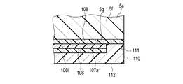
第18シート部材106lは、カーラ5Aの蓋部5eに接合される第2対向部107Aを有する。第2対向部107Aは、第18シート部材106lの、蓋部5eに対向する部分であり、第18シート部材106lの、蓋部5eに対向しない部位に比較して、幅方向に広い形状に構成される。
さらに、第2対向部107Aの面形状は、蓋部5eの面形状より、例えば、大きい形状に構成される。具体例として、第2対向部107Aは、第18シート部材106lの長手方向で第2対向部107Aの両側の部分に比較して、幅方向に延出する第2羽部107a1を有する。第2羽部107aは、第18シート部材106lの幅方向で両側に1つずつ形成される。第2羽部107a1は、一例として、面形状で蓋部5eの第3羽部5fの縁の円弧よりも大径の円弧状の縁を有する形状に構成される。
第2対向部107Aは、蓋部5eに、接着材や両面テープ等により構成される接着層108により、接着されることで接合される。第2対向部107Aの面形状が、第1対向部5aの面形状よりも大きい形状に構成されることから、第2羽部107a1は、接着層108により接着されることで、蓋部5eの第3羽部5fに接合される。さらに、一例として、第2羽部107a1は、第3羽部5fの切欠部5hにも接合される。第2対向部107Aの第2羽部107a1を除いた領域は、蓋部5eの第3羽部5fを除いた領域に、接着層108により接着されることで接合される。
なお、第2羽部107a1は、その一部が蓋部5eの切欠部5hに接合される構成を説明したが、これに限定されない。他の例では、第2羽部107a1は、第3羽部5fの手首200側の裏面5gのうち、切欠部5h以外の領域に接合される形状を有する構成であってもよい。
このように構成された第2の実施形態に係る血圧測定装置1は、第1の実施形態と同様の効果が得られる。さらに、血圧測定装置1を構成する部品数を少なくできる。
[第3の実施形態]
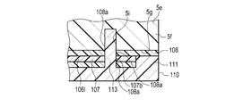
次に、血圧測定装置1の第3の実施形態について、図21及び図22を用いて説明する。なお、第3の実施形態に係る血圧測定装置1は、甲カフ74の第18シート部材106lの第2羽部107a1を、カーラ5Aの蓋部5eの第3羽部5fとの間に狭持するカバー部材110を備える構成であり、この点で、上述した第2の実施形態に係る血圧測定装置1と異なる。
[第3の実施形態]
次に、血圧測定装置1の第3の実施形態について、図21及び図22を用いて説明する。なお、第3の実施形態に係る血圧測定装置1は、甲カフ74の第18シート部材106lの第2羽部107a1を、カーラ5Aの蓋部5eの第3羽部5fとの間に狭持するカバー部材110を備える構成であり、この点で、上述した第2の実施形態に係る血圧測定装置1と異なる。
この為、第3の実施形態の血圧測定装置1の構成のうち、上述した第1の実施形態に係る血圧測定装置1と同様の構成については同一符号を付して説明するとともに、その説明及び図示を適宜省略する。
図21は、甲カフ74の2つの第2羽部107a1のうち一方の近傍を手首200側から見た下面図である。図22は、甲カフ74の2つの第2羽部107aのうち一方を示す断面図であり、図19に示すXXII-XXII線断面で示す断面図である。図21及び図22に示すように、血圧測定装置1は、第2の実施形態の構成に加えて、さらに、2つのカバー部材110を備える。
第2羽部107a1の縁は、第3羽部5fの裏面5gの縁の切欠部5hの内径よりも小さい径を有する円弧に構成される。第2羽部107a1は、接着層108により、第3羽部5fの手首200側の裏面5g面の切り欠き5gを除いた領域に接着されることで接合される。
カバー部材110は、第2羽部107a1を、第3羽部5fとの間に狭持する。カバー部材110の面形状は、外縁の一部が円弧状に形成され、残りの部分が直線状に形成される形状に構成される。カバー部材110は、円弧状に形成される縁を、蓋部5eの円弧状の縁に対向させる。カバー部材110の、円弧状の縁の径は、蓋部5eの円弧状の縁の径と同径である。
カバー部材110は、円弧状の縁に構成された縁部111を有する。カバー部材110は、縁部111の高さが、他部に比較して高く形成されている。縁部111は、蓋部5eの切欠部5hに配置される。ここで言う高さは、カバー部材110の手首200側の裏面112からの高さである。
また、縁部111の高さは、縁部111の先端が接着層108により切欠部5hに接合されたときに、カバー部材110の縁部111以外の領域、及び蓋部5eの第3羽部5fの切欠部5h以外の領域の間に、2つの接着層108、及び第2羽部107a1を挟持可能な寸法を有する。
このように構成されたカバー部材110では、縁部111が接着層108により、蓋部5eの切欠部5hに接着されることで接合される。また、カバー部材110の蓋部5e側の面のうち、縁部111以外の領域は、接着層108により、第2羽部107a1に接着されることで接合される。
このように構成された第3の実施形態にかかる血圧測定装置1は、第2の実施形態と同様の効果が得られる。さらに、第2羽部107a1がカバー部材110とカーラ5に接着されて狭持されることにより、甲カフ74及びカーラ5の接合強度をより一層向上できる。
なお、本発明は上述した実施形態に限定されない。例えば、血圧測定装置1の血圧測定時における第1開閉弁16A及び第2開閉弁16Bの開閉のタイミングは、上述した例に限定されず、適宜設定できる。また、血圧測定装置1は、血圧測定を平カフ71の加圧過程において測定した圧力で血圧を算出する例を説明したがこれに限定されず、減圧過程で血圧を算出してもよく、また、加圧過程及び減圧過程の双方で血圧を算出してもよい。
また、上述した例では、平カフ71は、空気袋81を各シート部材86によって形成する構成を説明したがこれに限定されず、例えば、平カフ71の変形や膨張を管理するために、さらに、空気袋81は他の構成を含んでいても良い。
また、上述した例では、背板72は、複数の溝72aを有する構成を説明したがこれに限定されない。例えば、背板72は、変形しやすさ等を管理するために、複数の溝72aの数や深さ等を適宜設定可能であり、また、変形を抑制する部材を含む構成であってもよい。
また、上述した第3の実施形態では、蓋部5eは、切欠部5hを有する構成を説明したこれに限定されない。例えば、図23に示す変形例のように、蓋部5eは、切欠部5hを有さない構成であってもよい。
また、上述した第3の実施形態では、カバー部材110は、接着層108による接着により蓋部5eに接合される構成を説明したが、これに限定されない。例えば、図24及び図25に示す変形例のように、カバー部材110は、さらに、一部が嵌め合いにより蓋部5eに固定される構成であってもよい。図24は、2つの第2羽部107a1のうち一方の近傍を手首200側から見た下面図である。図25は、甲カフ74の2つの第2羽部107a1のうち一方の近傍の構成を示す断面図であり、図24に示すXXV-XXV線断面で示す断面図である。
具体例として、図24及び図25に示すように、蓋部5eの第3羽部5fの手首200側の裏面5gには、孔5iが形成される。孔5iは、例えば複数、一例として2つ形成されている。これら2つの孔5iは、例えばカーラ5の長手方向に並んで配置されている。孔5iは、例えば、半円状に構成される。
第2羽部107a1及び接着層108の、孔5iと対向する部位にはそれぞれ、孔107b及び孔108aが形成される。
カバー部材110の第2羽部107a1の孔107bに対向する部位にはそれぞれ、突部113が形成される。突部113は、孔107b,108aに挿通される。さらに、突部113は、孔108aを通過した先端側の部分が、孔5iに嵌る。突部113は、例えば、軸方向に直交する断面が孔5iに嵌る半円状に形成される、柱状に構成される。突部113の一部は、孔107b,108aに配置される。また、突部113の孔108aを通過した部分は、孔5iに嵌合する。
このように、突部113が孔5iに嵌合することにより、カバー部材110が機械的にカーラ5Aに固定されることから、カバー及びカーラ5の固定強度を向上することが可能となる。なお、図24及び図25に示す変形例では、蓋部5eの裏面5gの円弧状の縁は、一例として、切欠部5hを有さない構成である。
また、上述した第3の実施形態では、カバー部材110は、接着層108により接着されることで、蓋部5eに接合される構成が説明されたが、これに限定されない。例えば、図26及び図27に示す変形例のように、カバー部材110は、蓋部5eに、溶着により接合されてもよい。図26は、甲カフ74の2つの第2羽部107a1のうち一方の近傍を手首200側から見た下面図である。図27は、甲カフ74の2つの第2羽部107a1のうち一方の近傍の構成を示す断面図であり、図26に示すXXVII-XXVII線断面で示す断面図である。
図26及び図27に示すように、第3羽部5fの裏面5gは、円弧状の縁部が、他に比較してカバー部材110側に突出する突部5jに構成される。突部5jの高さは、裏面5gの突部5j以外の領域及びカバー部材110の間に、第2羽部107a1、及び2つの接着層108を挟持可能な寸法を有する。カバー部材110の縁部111は、第3羽部5fの縁部に、溶着されることで、接合される。溶着の手段は、一例として、熱圧着である。
また、上述した第3の実施形態では、カバー部材110が蓋部5eに接着層108により接着されることで接合される構成が説明されたが、これに限定されない。例えば、図28及び図29に示す変形例のように、カバー部材110は、接着層108により接合に加えて、さらに、外郭ケース31内に嵌合することで、外郭ケース31に固定されてもよい。
図28は、甲カフ74の2つの第2羽部107a1のうちの一方の近傍を手首200側から見た下面図である。図29は、甲カフ74の2つの第2羽部107a1のうちの一方の近傍の構成を示す断面図であり、図28に示すXXIV-XXIV線断面で示す断面図である。
具体例として、第3羽部5fの裏面5gは、蓋部5eの第3羽部5fより幅方向で内側の裏面よりも、一段低い形状に構成される。すなわち、図29に示すように、裏面5gは、蓋部5eの裏面のうち第3羽部5fより幅方向で内側の領域に比較して、上方に位置する。
さらに、蓋部5eの円弧面に構成される第3羽部5fの側面5kは異なる径を有する複数円弧面部を有する。さらなる具体例として、側面5kは、第1円弧面部5k1と、第2円弧面部5k2と、第3円弧面部5k3と、を有する。
第1円弧面部5k1は、側面5kのうち、最も大径状に構成される部分である。第2円弧面部5k2は、第1円弧面部5k1の曲率中心と同じ軸上に曲率中心を有する円弧面に構成される。第2円弧面部5k2は、第1円弧面部5k1よりも小径の円弧面に構成される。第3円弧面部5k3は、第1円弧面部5k1の曲率中心と同軸上に曲率中心を有する円弧面に構成される。第3円弧面部5k3は、第2円弧面部5k2よりも小径の円弧面に構成される。
また、側面5kが、円弧面部5k1,5k2,5k3を有することから、第3羽部5fの裏面5gは、中央に配置される第1裏面部5g1と、第1裏面部5g1より外側に配置される第2裏面部5g2と、を有する。
第2羽部107a1は、接着層108により、第1裏面部5g1と、第2裏面部5g2とに、接着されることで接合される。
カバー部材110は、具体例として、縁部111が、第2羽部107a1の、第2裏面部5g2に接合された領域に、接着層108により接着されることで、接合される。カバー部材110の縁部111以外の領域は、第2羽部107aの、第1の裏面部5b1に接合された領域に、接着層108により接着されることで接合される。
外郭ケース31は、カバー部材110の一部、及び蓋部5eを内部に嵌合する。
このように、カバー部材110の一部、及び蓋部5eが外郭ケース31内に嵌合することで、カーラ5A及びケース11の固定強度、並びに、カバー部材110及びケース11の固定強度を向上することが可能となる。さらに、カバー部材110と蓋部5eとの接合部が外郭ケース31により覆われるので、カバー部材110と蓋部5eとの接合部にシール性を向上できる。ここで言う接合部は、縁部111の線端面、接着層108、及び、第2裏面部5g2を含む部分である。
また、上述した第3の実施形態では、第2羽部107aは、接着層108により蓋部5eに接合される構成を説明したこれに限定されない。例えば、第2羽部107aは、蓋部5eに、接合部材により接合されてもよい。接合部材とは、二つの部材を機械的に接合する部材であり、例えば、カシメ用の突起、リベット、縫製用の糸等を含む。
また、上述した、図21乃至図29に示された変形例は、カーラ5Aが蓋部5eを有する構成が説明されたが、これに限定されない。図21乃至図29に示された変形例は、第1の実施形態と同様に、裏蓋35を有するケース11と、第1対向部5aを有するカーラ5とを備える構成であってもよい。
また、上述した、第1乃至第3の実施形態、及び、図21乃至図29に示す第3の実施形態の変形例では、カーラ5が厚み方向に外郭ケース31の端部に並んで他の部位よりも幅方向に広い第1対向部5aを有し、第18シート部材106lがカーラ5の第1対向部5aに対向して他の部位よりも幅方向に広い第2対向部107を有する構成が一例として説明されたが、これに限定されない。他の例では、カーラ5の第1対向部5aが他の部位と幅方向に同じ幅を有する構成であってもよい。この構成であっても、第18シート部材106lの第2対向部107によって、接合代が増えるので、甲カフ74及びカーラ5の接合強度を向上できる。
また、上述した、第1乃至第3の実施形態、及び、図21乃至図29に示す第3の実施形態の変形例では、カーラ5が厚み方向に外郭ケース31の端部に並んで他の部位よりも幅方向に広い第1対向部5aを有し、第18シート部材106lがカーラ5の第1対向部5aに対向して他の部位よりも幅方向に広い第2対向部107を有する構成が一例として説明されたが、これに限定されない。他の例では、カーラ5の第1対向部5aが他の部位と幅方向に同じ幅を有する構成であってもよい。この構成であっても、第18シート部材106lの第2対向部107によって、接合代が増えるので、甲カフ74及びカーラ5の接合強度を向上できる。
即ち、上述した各実施形態は、あらゆる点において本発明の例示に過ぎない。本発明の範囲を逸脱することなく種々の改良や変形を行うことができることは言うまでもない。つまり、本発明の実施にあたって、実施形態に応じた具体的構成が適宜採用されてもよい。
1…血圧測定装置
3…装置本体
4…ベルト
5、5A…カーラ
5a…第1対向部
5a1…第1羽部
5e…蓋部
5f…第3羽部
5g…裏面
5g1…第1裏面部
5g2…第2裏面部
5i…孔
5j…突部
6…カフ構造体
7…流体回路
7a…第1流路
7b…第2流路
7c…第3流路
11…ケース
12…表示部
13…操作部
14…ポンプ
15…流路部
16…開閉弁
16A…第1開閉弁
16B…第2開閉弁
17…圧力センサ
17A…第1圧力センサ
17B…第2圧力センサ
18…電力供給部
19…振動モータ
20…制御基板
31…外郭ケース
31a…ラグ
31b…バネ棒
32…風防
33…基部
35…裏蓋
35a…ビス
41…釦
42…センサ
43…タッチパネル
51…基板
52…加速度センサ
53…通信部
54…記憶部
55…制御部
61…第1ベルト
61a…第1孔部
61b…第2孔部
61c…尾錠
61d…枠状体
61e…つく棒
62…第2ベルト
62a…小孔
62b…第3孔部
71…平カフ(カフ)
71A…押圧カフ
72…背板
72a…溝
73…センシングカフ
74…甲カフ(カフ)
75…フラット板
76…袋状カバー体
81…空気袋(袋状構造体)
81a…溶着部
82…挿入孔
86…シート部材
86a…第1シート部材
86b…第2シート部材
86b1…開口
86c…第3シート部材
86c1…開口
86d…第4シート部材
91…空気袋(袋状構造体)
92…チューブ
93…接続部
96…シート部材
96a…第5シート部材
96b…第6シート部材
101…空気袋(袋状構造体)
101a…溶着部
102…チューブ
103…接続部
106…シート部材
106a…第7シート部材
106b…第8シート部材
106b1…開口
106c…第9シート部材
106c1…開口
106d…第10シート部材
106d1…開口
106e…第11シート部材
106e1…開口
106f…第12シート部材
106f1…開口
106g…第13シート部材
106g1…開口
106h…第14シート部材
106h1…開口
106i…第15シート部材
106i1…開口
106j…第16シート部材
106j1…開口
106k…第17シート部材
106k1…開口
106l…第18シート部材
107、107A…第2対向部
107a…第2羽部
107a1…第2羽部
107b…孔
108…接着層
110…カバー部材
111…縁部
113…突部
200…手首
210…動脈
Claims (6)
- 筒状の外郭ケースを含むケースと、
生体の装着する部位の周方向に倣って湾曲し、厚み方向に前記外郭ケースの一端に並ぶ第1対向部を有するカーラと、
樹脂材料で形成された二枚のシート部材で形成され、流体により膨張し、前記カーラ側に配置される前記シート部材の前記第1対向部に対向する第2対向部が、他の部位よりも幅方向に広いカフと、
を備える血圧測定装置。 - 前記第1対向部は、前記カーラの他の部位よりも幅方向に広い形状に構成される、請求項1に記載の血圧測定装置。
- 前記第2対向部の、前記他の部位よりも前記幅方向に突出する部分を前記第1対向部との間に狭持するカバー部材を備える、請求項2に記載の血圧測定装置。
- 前記カバー部材は、突部を有し、
前記第2対向部は、前記突部の一部を配置する孔を有し、
前記第1対向部は、前記突部の一部が嵌合する嵌合部を有する
請求項3に記載の血圧測定装置。 - 前記ケースは、前記外郭ケースの前記一端を覆う裏蓋を備え、
第1対向部は、前記裏蓋に接続される
請求項1に記載の血圧測定装置。 - 前記第1対向部は、前記外郭ケースの前記一端を覆う
請求項2に記載の血圧測定装置。
Priority Applications (3)
| Application Number | Priority Date | Filing Date | Title |
|---|---|---|---|
| DE112019004833.3T DE112019004833T5 (de) | 2018-10-30 | 2019-09-27 | Blutdruckmessvorrichtung |
| CN201980063655.4A CN112788987A (zh) | 2018-10-30 | 2019-09-27 | 血压测定装置 |
| US17/224,427 US20210236012A1 (en) | 2018-10-30 | 2021-04-07 | Blood pressure measurement device |
Applications Claiming Priority (2)
| Application Number | Priority Date | Filing Date | Title |
|---|---|---|---|
| JP2018-204204 | 2018-10-30 | ||
| JP2018204204A JP7154949B2 (ja) | 2018-10-30 | 2018-10-30 | 血圧測定装置 |
Related Child Applications (1)
| Application Number | Title | Priority Date | Filing Date |
|---|---|---|---|
| US17/224,427 Continuation US20210236012A1 (en) | 2018-10-30 | 2021-04-07 | Blood pressure measurement device |
Publications (1)
| Publication Number | Publication Date |
|---|---|
| WO2020090314A1 true WO2020090314A1 (ja) | 2020-05-07 |
Family
ID=70464039
Family Applications (1)
| Application Number | Title | Priority Date | Filing Date |
|---|---|---|---|
| PCT/JP2019/038388 WO2020090314A1 (ja) | 2018-10-30 | 2019-09-27 | 血圧測定装置 |
Country Status (5)
| Country | Link |
|---|---|
| US (1) | US20210236012A1 (ja) |
| JP (1) | JP7154949B2 (ja) |
| CN (1) | CN112788987A (ja) |
| DE (1) | DE112019004833T5 (ja) |
| WO (1) | WO2020090314A1 (ja) |
Families Citing this family (1)
| Publication number | Priority date | Publication date | Assignee | Title |
|---|---|---|---|---|
| US11744476B2 (en) | 2020-08-20 | 2023-09-05 | Apple Inc. | Blood pressure measurement using device with piezoelectric sensor |
Citations (6)
| Publication number | Priority date | Publication date | Assignee | Title |
|---|---|---|---|---|
| JPS60126138A (ja) * | 1983-12-14 | 1985-07-05 | 松下電工株式会社 | 血圧計の排気弁 |
| WO2004080299A1 (ja) * | 2003-03-11 | 2004-09-23 | Terumo Kabushiki Kaisha | 血圧計用カフ及びそれを備えた血圧計 |
| WO2007074589A1 (ja) * | 2005-12-27 | 2007-07-05 | Omron Healthcare Co., Ltd. | 血圧計用カフおよびこれを備えた血圧計 |
| WO2016101888A1 (zh) * | 2014-12-24 | 2016-06-30 | 深圳瑞光康泰科技有限公司 | 气囊袖带及自动血压测量装置 |
| JP2018102859A (ja) * | 2016-12-28 | 2018-07-05 | オムロン株式会社 | 血圧計および血圧測定方法並びに機器 |
| JP2018521761A (ja) * | 2015-07-08 | 2018-08-09 | セルイージス デバイシィズ インコーポレイテッドCellaegis Devices Inc. | 対象における遠隔虚血コンディショニング(ric)を実行するために設定可能なシステム |
Family Cites Families (1)
| Publication number | Priority date | Publication date | Assignee | Title |
|---|---|---|---|---|
| JP4595526B2 (ja) * | 2004-12-20 | 2010-12-08 | オムロンヘルスケア株式会社 | 血圧計用カフおよび血圧計 |
-
2018
- 2018-10-30 JP JP2018204204A patent/JP7154949B2/ja active Active
-
2019
- 2019-09-27 WO PCT/JP2019/038388 patent/WO2020090314A1/ja active Application Filing
- 2019-09-27 CN CN201980063655.4A patent/CN112788987A/zh active Pending
- 2019-09-27 DE DE112019004833.3T patent/DE112019004833T5/de active Pending
-
2021
- 2021-04-07 US US17/224,427 patent/US20210236012A1/en active Pending
Patent Citations (6)
| Publication number | Priority date | Publication date | Assignee | Title |
|---|---|---|---|---|
| JPS60126138A (ja) * | 1983-12-14 | 1985-07-05 | 松下電工株式会社 | 血圧計の排気弁 |
| WO2004080299A1 (ja) * | 2003-03-11 | 2004-09-23 | Terumo Kabushiki Kaisha | 血圧計用カフ及びそれを備えた血圧計 |
| WO2007074589A1 (ja) * | 2005-12-27 | 2007-07-05 | Omron Healthcare Co., Ltd. | 血圧計用カフおよびこれを備えた血圧計 |
| WO2016101888A1 (zh) * | 2014-12-24 | 2016-06-30 | 深圳瑞光康泰科技有限公司 | 气囊袖带及自动血压测量装置 |
| JP2018521761A (ja) * | 2015-07-08 | 2018-08-09 | セルイージス デバイシィズ インコーポレイテッドCellaegis Devices Inc. | 対象における遠隔虚血コンディショニング(ric)を実行するために設定可能なシステム |
| JP2018102859A (ja) * | 2016-12-28 | 2018-07-05 | オムロン株式会社 | 血圧計および血圧測定方法並びに機器 |
Also Published As
| Publication number | Publication date |
|---|---|
| US20210236012A1 (en) | 2021-08-05 |
| DE112019004833T5 (de) | 2021-06-10 |
| JP7154949B2 (ja) | 2022-10-18 |
| CN112788987A (zh) | 2021-05-11 |
| JP2020068993A (ja) | 2020-05-07 |
Similar Documents
| Publication | Publication Date | Title |
|---|---|---|
| WO2020095990A1 (ja) | 血圧測定装置 | |
| CN111526783B (zh) | 血压测量装置 | |
| CN111511278B (zh) | 血压测量装置 | |
| JP7019415B2 (ja) | 血圧測定装置 | |
| US20210212579A1 (en) | Blood pressure measurement device | |
| WO2020090314A1 (ja) | 血圧測定装置 | |
| WO2020137476A1 (ja) | 血圧測定装置 | |
| WO2020121883A1 (ja) | 血圧測定装置 | |
| US20200345250A1 (en) | Blood pressure measurement device | |
| WO2020095991A1 (ja) | 血圧測定装置 | |
| WO2020080074A1 (ja) | 血圧測定装置 | |
| JP7019416B2 (ja) | 血圧測定装置 | |
| CN111526784B (zh) | 血压测量装置 | |
| WO2020137479A1 (ja) | 血圧測定装置 | |
| WO2020121884A1 (ja) | 血圧測定装置 |
Legal Events
| Date | Code | Title | Description |
|---|---|---|---|
| 121 | Ep: the epo has been informed by wipo that ep was designated in this application |
Ref document number: 19879166 Country of ref document: EP Kind code of ref document: A1 |
|
| 122 | Ep: pct application non-entry in european phase |
Ref document number: 19879166 Country of ref document: EP Kind code of ref document: A1 |