WO2020079935A1 - Système et corps volant - Google Patents
Système et corps volant Download PDFInfo
- Publication number
- WO2020079935A1 WO2020079935A1 PCT/JP2019/031738 JP2019031738W WO2020079935A1 WO 2020079935 A1 WO2020079935 A1 WO 2020079935A1 JP 2019031738 W JP2019031738 W JP 2019031738W WO 2020079935 A1 WO2020079935 A1 WO 2020079935A1
- Authority
- WO
- WIPO (PCT)
- Prior art keywords
- aircraft
- unit
- antenna
- flying body
- attachment
- Prior art date
Links
- 238000004891 communication Methods 0.000 claims abstract description 235
- 230000005540 biological transmission Effects 0.000 claims abstract description 27
- 239000000446 fuel Substances 0.000 claims description 29
- 230000007246 mechanism Effects 0.000 description 26
- 238000000034 method Methods 0.000 description 18
- 230000008569 process Effects 0.000 description 12
- 239000003381 stabilizer Substances 0.000 description 11
- 238000010248 power generation Methods 0.000 description 8
- 238000012545 processing Methods 0.000 description 7
- 239000005437 stratosphere Substances 0.000 description 4
- 238000012546 transfer Methods 0.000 description 4
- 230000002708 enhancing effect Effects 0.000 description 3
- 239000002828 fuel tank Substances 0.000 description 3
- RZVHIXYEVGDQDX-UHFFFAOYSA-N 9,10-anthraquinone Chemical group C1=CC=C2C(=O)C3=CC=CC=C3C(=O)C2=C1 RZVHIXYEVGDQDX-UHFFFAOYSA-N 0.000 description 2
- 230000008859 change Effects 0.000 description 2
- 230000010365 information processing Effects 0.000 description 2
- 230000001502 supplementing effect Effects 0.000 description 2
- UFHFLCQGNIYNRP-UHFFFAOYSA-N Hydrogen Chemical compound [H][H] UFHFLCQGNIYNRP-UHFFFAOYSA-N 0.000 description 1
- 238000013459 approach Methods 0.000 description 1
- 230000015572 biosynthetic process Effects 0.000 description 1
- 230000007423 decrease Effects 0.000 description 1
- 230000001419 dependent effect Effects 0.000 description 1
- 230000005674 electromagnetic induction Effects 0.000 description 1
- 238000005516 engineering process Methods 0.000 description 1
- 238000005755 formation reaction Methods 0.000 description 1
- 239000003502 gasoline Substances 0.000 description 1
- 239000001257 hydrogen Substances 0.000 description 1
- 229910052739 hydrogen Inorganic materials 0.000 description 1
- 230000007774 longterm Effects 0.000 description 1
- 238000012986 modification Methods 0.000 description 1
- 230000004048 modification Effects 0.000 description 1
- 238000012544 monitoring process Methods 0.000 description 1
- 230000002093 peripheral effect Effects 0.000 description 1
- 239000007787 solid Substances 0.000 description 1
Images


Classifications
-
- H—ELECTRICITY
- H04—ELECTRIC COMMUNICATION TECHNIQUE
- H04B—TRANSMISSION
- H04B7/00—Radio transmission systems, i.e. using radiation field
- H04B7/14—Relay systems
- H04B7/15—Active relay systems
- H04B7/185—Space-based or airborne stations; Stations for satellite systems
- H04B7/18502—Airborne stations
- H04B7/18504—Aircraft used as relay or high altitude atmospheric platform
-
- B—PERFORMING OPERATIONS; TRANSPORTING
- B64—AIRCRAFT; AVIATION; COSMONAUTICS
- B64C—AEROPLANES; HELICOPTERS
- B64C1/00—Fuselages; Constructional features common to fuselages, wings, stabilising surfaces or the like
- B64C1/36—Fuselages; Constructional features common to fuselages, wings, stabilising surfaces or the like adapted to receive antennas or radomes
-
- B—PERFORMING OPERATIONS; TRANSPORTING
- B64—AIRCRAFT; AVIATION; COSMONAUTICS
- B64C—AEROPLANES; HELICOPTERS
- B64C37/00—Convertible aircraft
- B64C37/02—Flying units formed by separate aircraft
-
- B—PERFORMING OPERATIONS; TRANSPORTING
- B64—AIRCRAFT; AVIATION; COSMONAUTICS
- B64D—EQUIPMENT FOR FITTING IN OR TO AIRCRAFT; FLIGHT SUITS; PARACHUTES; ARRANGEMENTS OR MOUNTING OF POWER PLANTS OR PROPULSION TRANSMISSIONS IN AIRCRAFT
- B64D27/00—Arrangement or mounting of power plant in aircraft; Aircraft characterised thereby
- B64D27/02—Aircraft characterised by the type or position of power plant
- B64D27/24—Aircraft characterised by the type or position of power plant using steam, electricity, or spring force
-
- B—PERFORMING OPERATIONS; TRANSPORTING
- B64—AIRCRAFT; AVIATION; COSMONAUTICS
- B64D—EQUIPMENT FOR FITTING IN OR TO AIRCRAFT; FLIGHT SUITS; PARACHUTES; ARRANGEMENTS OR MOUNTING OF POWER PLANTS OR PROPULSION TRANSMISSIONS IN AIRCRAFT
- B64D39/00—Refuelling during flight
-
- B—PERFORMING OPERATIONS; TRANSPORTING
- B64—AIRCRAFT; AVIATION; COSMONAUTICS
- B64D—EQUIPMENT FOR FITTING IN OR TO AIRCRAFT; FLIGHT SUITS; PARACHUTES; ARRANGEMENTS OR MOUNTING OF POWER PLANTS OR PROPULSION TRANSMISSIONS IN AIRCRAFT
- B64D39/00—Refuelling during flight
- B64D39/06—Connecting hose to aircraft; Disconnecting hose therefrom
-
- G—PHYSICS
- G08—SIGNALLING
- G08G—TRAFFIC CONTROL SYSTEMS
- G08G5/00—Traffic control systems for aircraft, e.g. air-traffic control [ATC]
- G08G5/0004—Transmission of traffic-related information to or from an aircraft
- G08G5/0013—Transmission of traffic-related information to or from an aircraft with a ground station
-
- G—PHYSICS
- G08—SIGNALLING
- G08G—TRAFFIC CONTROL SYSTEMS
- G08G5/00—Traffic control systems for aircraft, e.g. air-traffic control [ATC]
- G08G5/0017—Arrangements for implementing traffic-related aircraft activities, e.g. arrangements for generating, displaying, acquiring or managing traffic information
- G08G5/0021—Arrangements for implementing traffic-related aircraft activities, e.g. arrangements for generating, displaying, acquiring or managing traffic information located in the aircraft
-
- G—PHYSICS
- G08—SIGNALLING
- G08G—TRAFFIC CONTROL SYSTEMS
- G08G5/00—Traffic control systems for aircraft, e.g. air-traffic control [ATC]
- G08G5/0043—Traffic management of multiple aircrafts from the ground
-
- G—PHYSICS
- G08—SIGNALLING
- G08G—TRAFFIC CONTROL SYSTEMS
- G08G5/00—Traffic control systems for aircraft, e.g. air-traffic control [ATC]
- G08G5/0047—Navigation or guidance aids for a single aircraft
- G08G5/0069—Navigation or guidance aids for a single aircraft specially adapted for an unmanned aircraft
-
- H—ELECTRICITY
- H01—ELECTRIC ELEMENTS
- H01Q—ANTENNAS, i.e. RADIO AERIALS
- H01Q1/00—Details of, or arrangements associated with, antennas
- H01Q1/27—Adaptation for use in or on movable bodies
- H01Q1/28—Adaptation for use in or on aircraft, missiles, satellites, or balloons
- H01Q1/286—Adaptation for use in or on aircraft, missiles, satellites, or balloons substantially flush mounted with the skin of the craft
- H01Q1/287—Adaptation for use in or on aircraft, missiles, satellites, or balloons substantially flush mounted with the skin of the craft integrated in a wing or a stabiliser
-
- H—ELECTRICITY
- H04—ELECTRIC COMMUNICATION TECHNIQUE
- H04B—TRANSMISSION
- H04B7/00—Radio transmission systems, i.e. using radiation field
- H04B7/14—Relay systems
- H04B7/15—Active relay systems
- H04B7/185—Space-based or airborne stations; Stations for satellite systems
-
- H—ELECTRICITY
- H04—ELECTRIC COMMUNICATION TECHNIQUE
- H04B—TRANSMISSION
- H04B7/00—Radio transmission systems, i.e. using radiation field
- H04B7/14—Relay systems
- H04B7/15—Active relay systems
- H04B7/185—Space-based or airborne stations; Stations for satellite systems
- H04B7/1851—Systems using a satellite or space-based relay
- H04B7/18515—Transmission equipment in satellites or space-based relays
-
- B—PERFORMING OPERATIONS; TRANSPORTING
- B64—AIRCRAFT; AVIATION; COSMONAUTICS
- B64C—AEROPLANES; HELICOPTERS
- B64C13/00—Control systems or transmitting systems for actuating flying-control surfaces, lift-increasing flaps, air brakes, or spoilers
- B64C13/02—Initiating means
- B64C13/16—Initiating means actuated automatically, e.g. responsive to gust detectors
- B64C13/20—Initiating means actuated automatically, e.g. responsive to gust detectors using radiated signals
-
- B—PERFORMING OPERATIONS; TRANSPORTING
- B64—AIRCRAFT; AVIATION; COSMONAUTICS
- B64D—EQUIPMENT FOR FITTING IN OR TO AIRCRAFT; FLIGHT SUITS; PARACHUTES; ARRANGEMENTS OR MOUNTING OF POWER PLANTS OR PROPULSION TRANSMISSIONS IN AIRCRAFT
- B64D2221/00—Electric power distribution systems onboard aircraft
-
- B—PERFORMING OPERATIONS; TRANSPORTING
- B64—AIRCRAFT; AVIATION; COSMONAUTICS
- B64U—UNMANNED AERIAL VEHICLES [UAV]; EQUIPMENT THEREFOR
- B64U10/00—Type of UAV
- B64U10/25—Fixed-wing aircraft
-
- B—PERFORMING OPERATIONS; TRANSPORTING
- B64—AIRCRAFT; AVIATION; COSMONAUTICS
- B64U—UNMANNED AERIAL VEHICLES [UAV]; EQUIPMENT THEREFOR
- B64U2101/00—UAVs specially adapted for particular uses or applications
- B64U2101/20—UAVs specially adapted for particular uses or applications for use as communications relays, e.g. high-altitude platforms
-
- B—PERFORMING OPERATIONS; TRANSPORTING
- B64—AIRCRAFT; AVIATION; COSMONAUTICS
- B64U—UNMANNED AERIAL VEHICLES [UAV]; EQUIPMENT THEREFOR
- B64U2201/00—UAVs characterised by their flight controls
- B64U2201/10—UAVs characterised by their flight controls autonomous, i.e. by navigating independently from ground or air stations, e.g. by using inertial navigation systems [INS]
- B64U2201/102—UAVs characterised by their flight controls autonomous, i.e. by navigating independently from ground or air stations, e.g. by using inertial navigation systems [INS] adapted for flying in formations
-
- B—PERFORMING OPERATIONS; TRANSPORTING
- B64—AIRCRAFT; AVIATION; COSMONAUTICS
- B64U—UNMANNED AERIAL VEHICLES [UAV]; EQUIPMENT THEREFOR
- B64U2201/00—UAVs characterised by their flight controls
- B64U2201/20—Remote controls
-
- B—PERFORMING OPERATIONS; TRANSPORTING
- B64—AIRCRAFT; AVIATION; COSMONAUTICS
- B64U—UNMANNED AERIAL VEHICLES [UAV]; EQUIPMENT THEREFOR
- B64U30/00—Means for producing lift; Empennages; Arrangements thereof
- B64U30/10—Wings
-
- B—PERFORMING OPERATIONS; TRANSPORTING
- B64—AIRCRAFT; AVIATION; COSMONAUTICS
- B64U—UNMANNED AERIAL VEHICLES [UAV]; EQUIPMENT THEREFOR
- B64U50/00—Propulsion; Power supply
- B64U50/10—Propulsion
- B64U50/13—Propulsion using external fans or propellers
-
- B—PERFORMING OPERATIONS; TRANSPORTING
- B64—AIRCRAFT; AVIATION; COSMONAUTICS
- B64U—UNMANNED AERIAL VEHICLES [UAV]; EQUIPMENT THEREFOR
- B64U50/00—Propulsion; Power supply
- B64U50/10—Propulsion
- B64U50/19—Propulsion using electrically powered motors
-
- B—PERFORMING OPERATIONS; TRANSPORTING
- B64—AIRCRAFT; AVIATION; COSMONAUTICS
- B64U—UNMANNED AERIAL VEHICLES [UAV]; EQUIPMENT THEREFOR
- B64U50/00—Propulsion; Power supply
- B64U50/30—Supply or distribution of electrical power
- B64U50/31—Supply or distribution of electrical power generated by photovoltaics
-
- H—ELECTRICITY
- H04—ELECTRIC COMMUNICATION TECHNIQUE
- H04B—TRANSMISSION
- H04B7/00—Radio transmission systems, i.e. using radiation field
- H04B7/14—Relay systems
- H04B7/15—Active relay systems
- H04B7/185—Space-based or airborne stations; Stations for satellite systems
- H04B7/18502—Airborne stations
-
- H—ELECTRICITY
- H04—ELECTRIC COMMUNICATION TECHNIQUE
- H04W—WIRELESS COMMUNICATION NETWORKS
- H04W16/00—Network planning, e.g. coverage or traffic planning tools; Network deployment, e.g. resource partitioning or cells structures
- H04W16/24—Cell structures
- H04W16/28—Cell structures using beam steering
Definitions
- the present invention relates to an aircraft and a system.
- Patent Document 1 Japanese Patent Laid-Open No. 2002-211496
- an air vehicle may include an antenna for forming a communication area by a beam emitted toward the ground and providing a wireless communication service to a user terminal in the communication area.
- the air vehicle may include an attachment / detachment section that is physically attached to and detached from another air vehicle so as to be united and separated from the other air vehicle.
- the flight vehicle includes a control execution unit that controls the flight vehicle such that the attachment / detachment section and the attachment / detachment section included in the other flight vehicle are connected while the flight vehicle and the other flight vehicle are in flight.
- the aircraft may include an attachment / detachment communication unit that communicates with the another aircraft via the attachment / detachment unit.
- the flight vehicle may include a power transmission unit that transmits power to the other flight vehicle via the attachment / detachment unit.
- the aircraft may include a fuel supply / demand unit that supplies and receives fuel to / from the other aircraft via the attachment / detachment unit.
- the attachment / detachment portion may include a right wing side attachment / detachment portion arranged on the right wing side of the main wing of the aircraft and a left wing side attachment / detachment portion arranged on the left wing side of the main wing.
- the attachment / detachment section may further include at least one of an upper surface side attachment / detachment section arranged on the upper surface side of the flight vehicle and a lower surface side attachment / detachment section arranged on the lower surface side of the flight vehicle.
- the attachment / detachment section may include at least one of an upper surface side attachment / detachment section arranged on the upper surface side of the flight vehicle and a lower surface side attachment / detachment section arranged on the lower surface side of the flight vehicle.
- the upper surface side attachment / detachment portion may be arranged at a connection portion protruding from the upper surface of the aircraft to the rear of the aircraft, and the lower surface side attachment / detachment portion may be arranged from the lower surface of the aircraft to the front of the aircraft. It may be arranged at the connecting part projecting towards it.
- the antenna is a first central antenna arranged in the center of the main wing of the aircraft, a first left-wing antenna arranged in the left wing of the main wing of the aircraft, and a right wing of the main wing of the aircraft.
- a second central antenna disposed in the center of the main wing of the other flight vehicle, and a left wing of the main wing of the other flight vehicle.
- the second left-wing side antenna and the second right-wing side antenna arranged on the right wing of the main wing of the other flying body may be included.
- the air vehicle may include a ground communication unit that forms the communication area on the ground using the antenna, and the ground communication unit includes the first central antenna, the first left wing side antenna, and the first right wing side. Beamforming by an antenna, the second central antenna, the second left-side antenna, and the second right-side antenna may be controlled to form the communication area.
- a system may include a first air vehicle, a second air vehicle, and a third air vehicle.
- the first flying body is physically attached to and detached from an antenna for communicating with a ground communication device and a lower surface attaching / detaching portion arranged on the upper surface of the first flying body and on the lower surface of the second flying body. It may have an attachment / detachment section and an attachment / detachment communication section that communicates with the second aircraft via the attachment / detachment section.
- the second flight vehicle includes an antenna for communicating with other flight vehicles other than the first flight vehicle and the third flight vehicle, a lower surface attachment / detachment section arranged on a lower surface of the second flight vehicle, and a second flight vehicle.
- the upper surface attaching / detaching portion arranged on the upper surface of the aircraft and physically attached to / detaching the lower surface attaching / detaching portion arranged on the lower surface of the third aircraft, and communicating with the second aircraft via the lower surface attaching / detaching portion,
- a detachable communication unit that communicates with the third flying object via the detachable unit may be included.
- the third flying body has an antenna for communicating with a communication satellite, a lower surface attaching / detaching section arranged on a lower surface of the third flying body, and a detachable communication section for communicating with the second flying body via the lower surface attaching / detaching section.
- the first air vehicle may communicate with other air vehicles via the second air vehicle and the communication satellites via the third air vehicle.
- an air vehicle may include an antenna for forming a communication area by a beam emitted toward the ground and providing a wireless communication service to a user terminal in the communication area.
- the air vehicle may include a cable having an attachment / detachment portion that is physically attached to and detached from another air vehicle.
- the air vehicle may include a cable communication unit that communicates with other air vehicles via a cable.
- the air vehicle may include a power transfer unit that transfers power to and from another air vehicle via a cable.
- the flying body may include an attaching / detaching portion that physically attaches / detaches to / from an attaching / detaching portion included in a cable included in another flying body.
- an air vehicle may include an antenna for forming a communication area by a beam emitted toward the ground and providing a wireless communication service to a user terminal in the communication area.
- the air vehicle may include a wireless communication unit that wirelessly communicates with other air vehicles.
- the air vehicle may include a power transfer execution unit that performs wireless power transfer with another air vehicle.
- the aircraft has an interface capable of performing wireless communication with the wireless communication unit by the wireless communication unit and the power transmission execution unit, and having an interface capable of performing wireless power transmission with the power transmission execution unit. It may be virtually combined with other air vehicles of the same or different types.
- 1 schematically shows an example of a system 10.
- 1 schematically shows an example of an air vehicle 100.
- An example of the right wing side attachment / detachment section 140 is schematically shown.
- 1 schematically shows an example of an aircraft 100 that is united with an aircraft 200.
- 1 schematically shows an example of an aircraft 100 that is united with an aircraft 200 and an aircraft 300.
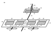
- 1 schematically shows an example of a communication area 600 formed by an air vehicle 100, an air vehicle 200, and an air vehicle 300.
- 1 schematically shows an example of an air vehicle 100, an air vehicle 200, and an air vehicle 300 that are vertically united.
- 1 schematically shows an example of an air vehicle 100, an air vehicle 200, and an air vehicle 300 that are united in an oblique direction.
- 1 schematically shows an example of an air vehicle 100, an air vehicle 200, and an air vehicle 300 that are united in an oblique direction.
- 1 schematically shows an example of an air vehicle 100, an air vehicle 200, and an air vehicle 300 that are united by a cable.
- 1 schematically shows an example of an air vehicle 100, an air vehicle 200, and an air vehicle 300 that are virtually united.
- An example of the functional configuration of the control device 400 is schematically shown.
- An example of the flow of processing by the control device 400 is schematically shown.
- 1 schematically shows an example of a control device 170 included in the aircraft 100.
- An example of the flow of processing by the control device 170 is schematically shown.
- An example of the hardware configuration of a computer 1000 that functions as the control device 400 or the control device 170 is schematically shown.
- FIG. 1 schematically shows an example of a system 10 according to this embodiment.
- the system 10 comprises a plurality of air vehicles.
- the system 10 also includes a control device 400.
- a flying body 100, a flying body 200, and a flying body 300 are illustrated as the plurality of flying bodies.
- the plurality of air vehicles may include air vehicles other than the air vehicle 100, the air vehicle 200, and the air vehicle 300.
- the air vehicle 100 forms a communication area 150 by a beam emitted toward the ground and provides a wireless communication service to the user terminal 30 in the communication area 150.
- the communication area 150 may be formed on the ground, and the air vehicle 100 may provide the wireless communication service to the user terminal 30 on the ground by the communication area 150.
- the communication area 150 may also be a three-dimensional communication area that targets the sky. When the communication area 150 is a three-dimensional communication area, the flying object 100 may provide the wireless communication service to the user terminal 30 such as a drone located in the sky.
- the air vehicle 100 patrols the stratosphere, for example, and provides a wireless communication service to the user terminal 30.
- Aircraft 100 may function as a stratosphere platform.
- the user terminal 30 may be any terminal as long as it can communicate with the flying object 100.
- the user terminal 30 is a mobile phone such as a smartphone.
- the user terminal 30 may be a tablet terminal, a PC (Personal Computer), or the like.
- the user terminal 30 may be a so-called IoT (Internet of Thing) device. Examples of the IoT device include various sensors and various actuators.
- the user terminal 30 may be a communication module mounted on a vehicle, a ship, a drone or the like.
- the user terminal 30 may include anything corresponding to so-called IoE (Internet of Everything).
- the air vehicle 100 may include a solar cell panel and a battery.
- the battery stores the electric power generated by the solar cell panel.
- the flying body 100 can fly by driving a propulsion mechanism such as a propeller with electric power stored in a battery.
- the air vehicle 100 may form the communication area 150 by the electric power stored in the battery.
- the air vehicle 100 covers the ground area by the communication area 150, for example, while traveling over the ground area to be covered. Turning the flying vehicle 100 over the ground area may be referred to as fixed point flight. Further, the air vehicle 100 covers the entire ground area by moving over the ground area while covering a part of the ground area to be covered by the communication area 150, for example.
- the air vehicle 100 has an antenna for forming a communication area 150.
- the antenna may be, for example, a multi-beam antenna.
- the communication area 150 may be composed of a plurality of subcells 152.
- the communication area 150 may be configured by one cell.
- the air vehicle 100 provides a wireless communication service to the user terminal 30 by relaying communication between the user terminal 30 and the ground network 20, for example.
- the network 20 may be any network, for example, the Internet, mobile phone networks such as so-called 3G (3rd Generation), LTE (Long Term Evolution), 4G (4th Generation) and 5G (5th Generation), and the public. It may include at least one of a wireless LAN (Local Area Network) and a dedicated network.
- the air vehicle 100 communicates with the network 20 on the ground via the gateway 40 in the communication area 150 among the gateways 40 arranged in various places on the ground, for example.
- the air vehicle 100 communicates with the ground network 20 via the communication satellite 50, for example.
- the air vehicle 100 has an antenna for communicating with the communication satellite 50.
- the air vehicle 100 communicates with other air vehicles.
- the air vehicle 100 communicates with other air vehicles via the network 20, for example. Further, the air vehicle 100 communicates with other air vehicles via the communication satellite 50, for example.
- the air vehicle 100 may wirelessly communicate with other air vehicles. Aircraft 100 may communicate directly with other air vehicles by wireless communication. In this case, the flying object 100 has an antenna for wireless communication with another flying object. The air vehicle 100 may form a C2 link with another air vehicle using the antenna, and may communicate via the C2 link, for example.
- the air vehicle 200 may have the same configuration as the air vehicle 100.
- the flying body 200 may have a partially different configuration from the flying body 100.
- the air vehicle 200 may be capable of providing a wireless communication service having a larger communication capacity than the wireless communication service provided by the air vehicle 100.
- the flying vehicle 200 may be larger than the flying vehicle 100, and may have an antenna larger than the antenna of the flying vehicle 100.
- the aircraft 200 may have a power supply unit that supplies power to other aircraft.
- the flying body 200 may include, for example, a propulsion mechanism that generates a stronger thrust than the propulsion mechanism mounted on the flying body 100.
- the air vehicle 300 may have the same configuration as the air vehicle 100, like the air vehicle 200.
- the flying object 300 may have a configuration partially different from that of the flying object 100, like the flying object 200.
- the control device 400 controls a plurality of flying objects.
- the control device 400 controls the plurality of air vehicles by transmitting an instruction to each of the plurality of air vehicles.
- the control device 400 controls a plurality of air vehicles so that the communication area 150 covers the ground communication area, for example.
- the control device 400 controls the combination of a plurality of flying vehicles.
- the control device 400 selects, for example, two or more air vehicles to be combined from a plurality of air vehicles, and transmits a control signal to the selected two or more air vehicles, thereby connecting the two or more air vehicles to each other. To coalesce.
- the control device 400 selects a flying body to be combined with the flying body 100 from a plurality of flying bodies, and controls to combine the selected flying body and the flying body 100.
- the control device 400 monitors, for example, various situations related to the aircraft 100, and when the situation satisfies a predetermined condition, the controller 400 determines the aircraft to be combined with the aircraft 100 according to the satisfied condition. select.
- the control device 400 selects an aircraft to be combined with the aircraft 100 when the communication traffic in the wireless communication service provided by the aircraft 100 exceeds a predetermined threshold value, for example.
- the control device 400 selects, for example, the air vehicle 200 having the same configuration as the air vehicle 100. Further, the control device 400 selects, for example, the aircraft 200 that provides a wireless communication service having a communication capacity larger than that of the wireless communication service provided by the aircraft 100.
- the control device 400 combines the flying body 100 and the flying body 200, and when the communication traffic in the wireless communication service by the flying body 100 and the flying body 200 exceeds a predetermined threshold, the flying body 100 and the flying body 200 An air vehicle that is further united with the body 200 may be selected.
- control device 400 selects the flying object 300 having the same configuration as the flying object 100. Further, the control device 400 selects, for example, the flying body 300 capable of providing a wireless communication service having a larger communication capacity than the wireless communication service of the flying body 100.
- control device 400 controls the solar cell panel to receive light when the battery level of the battery of the flying object 100 is less than a predetermined threshold value, when the amount of power generated by the solar cell panel is less than the predetermined threshold value.
- the control device 400 selects, for example, the aircraft 200 having the power supply unit.
- the control device 400 selects the flying object to be combined with the flying object 100.
- the control device 400 selects, for example, the air vehicle 200 having the same configuration as the air vehicle 100. Further, the control device 400 selects, for example, the flying body 200 having a propulsion mechanism that generates a stronger thrust than the propulsion mechanism mounted on the flying body 100.
- control device 400 may select an aircraft to be combined with the aircraft 100 according to an instruction from the operator. For example, when the operator wants to enhance the communication function of the air vehicle 100, to increase the power amount of the air vehicle 100, to increase the thrust of the air vehicle 100, and the like, the operator instructs the air vehicle 100 to be combined with the air vehicle 100. .
- the controller 400 may monitor the status related to the plurality of air vehicles by continuously receiving information related to the respective status from each of the plurality of air vehicles.
- the information may include position information of the air vehicle.
- the information may include a situation of a communication area formed by the air vehicle.
- the status of the communication area is, for example, communication traffic in the communication area and the size of the communication area.
- the information may include the status of the ground area covered by the air vehicle by the communication area.
- the status of the above-ground area includes whether the above-ground area is an urban area, whether it is a rural area, whether it is a super-rural area, whether there is a wireless communication area on the ground, etc. May be included.
- the controller 400 continuously receives information related to the status of each of the plurality of air vehicles from the management system 500 that manages the plurality of air vehicles to monitor the status of the plurality of air vehicles. Good.
- the management system 500 continuously receives information related to each situation from each of the plurality of air vehicles via the gateway 40 and the network 20, for example. Further, the management system 500 continuously receives information related to each situation from each of the plurality of air vehicles via the communication satellite 50, for example.
- the management system 500 may include a plurality of devices that collect various types of information, and may include only one device that collects various types of information.
- a plurality of flying vehicles are configured to be able to be joined together, and the control device 400 controls the joining of the plurality of flying vehicles according to the situation.
- the control device 400 controls the joining of the plurality of flying vehicles according to the situation.
- the flying body by reducing the size of the flying body, it is possible to take off by winch towing like a glider, and it is possible to reduce power consumption.
- the miniaturization of the flying body enables storage by a small hanger and facilitates provision of a temporary airfield. Further, by downsizing the flying body, it becomes easy to realize both the flying body and the small hanger by an assembly type, and it becomes possible to fly faster on-site in the event of a disaster or the like.
- FIG. 2 schematically shows an example of the air vehicle 100.
- the aircraft 100 illustrated in FIG. 2 includes a main body 102, a main wing 104, a horizontal stabilizer 106, a vertical stabilizer 107, a plurality of propellers 108, a central antenna 110, a left wing antenna 112, a right wing antenna 114, a GPS transceiver 116, and a solar cell.
- the panel 118 and the battery 120 are provided.
- the main wing 104 has a moving blade 122.
- the horizontal stabilizer 106 has a moving blade 124.
- the vertical stabilizer 107 has a rotor blade 126.
- the solar cell panel 118 is installed on at least one of the main wing 104, the horizontal stabilizer 106, and the vertical stabilizer 107.
- FIG. 2 illustrates the case where the solar cell panels 118 are installed on all of the main wing 104, the horizontal stabilizer 106, and the vertical stabilizer 107.
- the moving blade 122 is installed at the trailing edge of the main wing 104, and is used to tilt the airframe left and right.
- the rotor blade 122 may be a so-called aileron.
- the rotor blades 124 are installed at the trailing edge of the horizontal stabilizer 106 and are used to raise and lower the nose.
- the moving blades 124 may be so-called elevators.
- the rotor blade 126 is installed at the trailing edge of the vertical tail 107, and is used to turn the nose left and right.
- the moving blade 126 may be a so-called ladder.
- Aircraft 100 controls position and attitude by controlling propeller 108, rotor blades 122, rotor blades 124, and rotor blades 126.
- the battery 120 stores the electric power generated by the solar cell panel 118.
- the flying object 100 can fly by driving the propeller 108, the moving blades 122, the moving blades 124, and the moving blades 126 with the electric power stored in the battery 120.
- the aircraft 100 may include a fuel cell instead of the solar cell panel 118 and the battery 120. In this case, the flying object 100 can fly by driving the propeller 108 with the electric power supplied from the fuel cell.
- the fuel various arbitrary fuels such as hydrogen and gasoline can be adopted.
- the air vehicle 100 may include both a solar cell panel 118 and a battery 120, and a fuel cell.
- the propeller 108 may be an example of a propulsion mechanism.
- the air vehicle 100 may have only one propeller 108 or may have a plurality of propellers 108.
- FIG. 2 illustrates the case where the aircraft 100 has two propellers 108.
- the aircraft 100 may include a jet engine instead of the propeller 108.
- a jet engine may be an example of a propulsion mechanism.
- the central antenna 110, the left-side antenna 112, and the right-side antenna 114 form a communication area 150.
- the air vehicle 100 may include only a part of the central antenna 110, the left-wing antenna 112, and the right-wing antenna 114.
- the air vehicle 100 includes only the central antenna 110 among the central antenna 110, the left-wing antenna 112, and the right-wing antenna 114.
- the GPS transceiver 116 receives GPS signals.
- the air vehicle 100 may acquire the position information of the air vehicle 100 by a GPS signal received by the GPS transceiver 116.
- the GPS transceiver 116 may identify the position of the air vehicle 100 using the received GPS signal, and the air vehicle 100 may acquire the location information identified by the GPS transceiver 116.
- the aircraft 100 illustrated in FIG. 2 has an attachment / detachment portion that is physically attached to and detached from another aircraft in order to unite and separate the other aircraft.
- the aircraft 100 shown in FIG. 2 has a left-wing side attaching / detaching portion 130 and a right-wing side attaching / detaching portion 140.
- the left wing side attaching / detaching portion 130 is arranged on the left wing side of the main wing 104.
- the left wing side attachment / detachment unit 130 is arranged, for example, at the tip of the left wing of the main wing 104.
- the right wing side attaching / detaching portion 140 is arranged on the right wing side of the main wing 104.
- the right wing side attaching / detaching portion 140 is arranged, for example, at the tip of the right wing of the main wing 104.
- the air vehicle 200 may have the same configuration as the air vehicle 100 as described above, or may have a configuration partially different from the air vehicle 100.
- the aircraft 200 includes a power supply unit that supplies the power of the battery 120 to other aircraft.
- the battery included in the aircraft 200 may have a larger capacity than the battery 120 of the aircraft 100.
- the solar cell panel included in the aircraft 200 may generate more power than the solar cell panel 118 of the aircraft 100.
- the air vehicle 200 may not include an antenna for forming the communication area 150. That is, the flying body 200 may be a flying body for power replenishment that replenishes power to another flying body.
- the air vehicle 200 may include a central antenna, a left-wing antenna, and a right-wing antenna that are larger than the central antenna 110, the left-wing antenna 112, and the right-wing antenna 114.
- the flying object 200 may include more antennas than the flying object 100 as antennas for forming a communication area. That is, the flying object 200 may be a flying object for enhancing the communication function.
- the air vehicle 200 includes a propeller that generates a stronger thrust than the propeller 108 of the air vehicle 100.
- the air vehicle 200 includes a propeller having a motor having a higher output than that of the propeller 108 of the air vehicle 100.
- the air vehicle 200 may include more propellers than the air vehicle 100. In these cases, air vehicle 200 may not include an antenna to form communication area 150. That is, the aircraft 200 may be a thrust-enhancing aircraft that enhances the thrust of other aircraft.
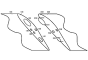
- FIG. 3 schematically shows an example of the right wing side attachment / detachment section 140 of the aircraft 100.
- the left wing side attachment / detachment portion 230 of the aircraft 200 is also shown in order to explain the connection with another aircraft.
- the left wing side attachment / detachment section 230 of the aircraft 200 has the same configuration as the left wing side attachment / detachment section 130 of the aircraft 100.
- the right wing side attachment / detachment section 140 has a structural concave connection section 142, a positioning sensor 144, a signal connection section 146, and a power connection section 148.
- the left wing side attachment / detachment portion 230 has a structural convex connection portion 232, a signal connection portion 236, and a power connection portion 238.
- the structural concave connecting portion 142 has a structure that fits with the structural convex connecting portion 232.
- two structural concave connection portions 142 are illustrated, but the number of structural concave connection portions 142 is not limited to this. Further, the relationship of the unevenness may be reversed between the right wing side attaching / detaching part 140 and the left wing side attaching / detaching part 230.
- the positioning sensor 144 measures the position of an object facing the positioning sensor 144.
- the positioning sensor 144 may be of any type such as a laser type, an ultrasonic type, and an infrared type.
- the positioning sensor 144 may be arranged in both the right wing side attaching / detaching part 140 and the left wing side attaching / detaching part 130.
- the signal connecting portion 146 connects with the signal connecting portion 236 when the structural concave connecting portion 142 and the structural convex connecting portion 232 are fitted together.
- the aircraft 100 can send and receive signals to and from the aircraft 200 via the signal connection unit 146.
- the power connecting portion 148 connects with the power connecting portion 238 when the structure concave connecting portion 142 and the structure convex connecting portion 232 are fitted together.
- the air vehicle 100 can perform power transmission with the air vehicle 200 via the power connection unit 148.
- the aircraft 100 may include a fuel pipe instead of the power connection unit 148.
- the fuel pipe may be connected to the fuel pipe arranged in the left wing side attaching / detaching portion 230 when the structural concave connection portion 142 and the structural convex connection portion 232 are fitted.
- the aircraft 100 can supply and demand fuel to and from the aircraft 200 via the fuel pipe.
- FIG. 4 schematically shows an example of the air vehicle 100 combined with the air vehicle 200.
- an example is shown in which the right wing side attachment / detachment section 140 of the aircraft 100 and the left wing side attachment / detachment section 230 of the aircraft 200 are connected to combine the aircraft 100 and the aircraft 200. .
- the air vehicle 100 can perform electric power transmission with the air vehicle 200 by being united with the air vehicle 200.
- the aircraft 100 receives electric power from the aircraft 200, for example. Further, the flying object 100 supplies power to the flying object 200, for example.
- the aircraft 100 can supply and demand fuel to and from the aircraft 200 by being combined with the aircraft 200.
- the aircraft 100 receives fuel from the aircraft 200, for example. Further, the aircraft 100 supplies fuel to the aircraft 200, for example.
- the air vehicle 100 can receive thrust by the air vehicle 200 or can give thrust to the air vehicle 200 by being united with the air vehicle 200.
- the air vehicle 100 can form a communication area in cooperation with the air vehicle 200 by being united with the air vehicle 200.
- the communication capacity can be increased, the communication area can be expanded, and the directivity can be increased, as compared with the case where the communication area is formed only by the flying object 100.
- the control device 400 transmits a control signal for combining with the flying object 200 to the flying object 100, for example, when the communication condition of the communication area 150 formed by the flying object 100 satisfies a predetermined condition.
- a predetermined condition As a specific example, when the communication traffic in the communication area 150 formed by the air vehicle 100 is higher than a predetermined threshold, the control device 400 transmits a control signal for combining with the air vehicle 200 to the air vehicle 100.
- the control device 400 may select the flying body 200 having the same configuration as that of the flying body 100, as a uniting target of the flying body 100. Further, the control device 400 may select, as a target to be combined with the aircraft 100, the aircraft 200 capable of providing a wireless communication service having a larger communication capacity than the wireless communication service provided by the aircraft 100. As a result, the communication capacity can be increased more efficiently.
- the control device 400 transmits a control signal for merging with the flying body 200 to the flying body 100 when the latitude of the flying body 100 satisfies a predetermined condition.
- control device 400 transmits to aircraft 100 a control signal for joining aircraft 200 when the latitude of aircraft 100 is higher than a predetermined latitude.
- the control device 400 may select the aircraft 200 having the power supply unit as a target to be combined with the aircraft 100. Further, the control device 400 may select an aircraft 200 that has a power supply unit and has a battery remaining amount that is greater than a predetermined threshold value, as a target for combining the aircraft 100.
- the control device 400 transmits a control signal for merging with the air vehicle 200 to the air vehicle 100 when the weather condition of the flight area of the air vehicle 100 satisfies a predetermined condition.
- the control device 400 transmits, to the air vehicle 100, a control signal for combining with the air vehicle 200 when the airflow velocity in the flight area of the air vehicle 100 is higher than a predetermined threshold value.
- the control device 400 may select the flying body 200 having the same configuration as that of the flying body 100, as a uniting target of the flying body 100.
- the control device 400 may select the aircraft 200 having a propulsion mechanism that generates a stronger thrust than the propulsion mechanism included in the aircraft 100. Thereby, a stronger thrust can be applied to the flying object 100.
- At least one of the plurality of propellers 108 included in the aircraft 100 and the plurality of propellers 208 included in the aircraft 200 may be stopped.
- the air vehicle 100 stops the left wing side propeller 108
- the air vehicle 200 stops the right wing side propeller 208.
- the flying body 100 stops the right-wing-side propeller 108
- the flying body 200 stops the left-wing-side propeller 208.
- the stop of the propeller may be executed by the flying body 100 and the flying body 200 independently, or may be executed by the flying body 100 and the flying body 200 under the control of the control device 400.
- FIG. 5 schematically shows an example of an air vehicle 100 combined with the air vehicle 200 and the air vehicle 300.
- FIG. 5 exemplifies a case where the flying body 200 and the flying body 300 are combined on both sides of the flying body 100, the invention is not limited to this, and the flying body 100 and the flying body 200 are combined, By combining 200 and the flying body 300, the flying body 100, the flying body 200, and the flying body 300 may be combined.
- the air vehicle 200 may be an air vehicle having the same configuration as the air vehicle 100.
- the aircraft 200 may also be a vehicle for supplementing power.
- the flying body 200 may be a flying body for thrust enhancement.
- the flying body 200 may be a flying body for enhancing communication function.
- the air vehicle 300 may be an air vehicle having the same configuration as the air vehicle 100. Further, the flying body 300 may be a flying body for supplementing power. Further, the flying object 300 may be a flying object for thrust enhancement. Further, the flying object 300 may be a flying object for enhancing the communication function.
- the flying body 100 can be compared with the case where only the flying body 200 is joined.
- the available power supply, fuel supply, communication capacity, and thrust can be increased.
- both the aircraft 100 and the aircraft 200 can be provided. And thrust can be applied efficiently.
- a plurality of propellers 108 included in the air vehicle 100, a plurality of propellers 208 included in the air vehicle 200, and a plurality of propellers 308 included in the air vehicle 300 are included. At least one may be stopped.
- the plurality of propellers 108 of the air vehicle 100 may be shut down.
- the propeller 208 on the right wing side of the aircraft 200 and the propeller 308 on the left wing side of the aircraft 300 may be stopped.
- the plurality of propellers 208 of the aircraft 200 and the plurality of propellers 308 of the aircraft 300 may be stopped.
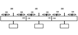
- FIG. 6 schematically shows an example of a communication area 600 formed by the air vehicle 100, the air vehicle 200, and the air vehicle 300.
- the air vehicle 100 includes a central antenna 110, a left-wing antenna 112, and a right-wing antenna 114
- the air vehicle 200 includes a central antenna 210, a left-wing antenna 212, and a right-wing antenna 214
- the air vehicle 300 includes a central antenna 310.
- the left-wing side antenna 312 and the right-wing side antenna 314 are illustrated.
- the air vehicle 100 includes beam forming with a central antenna 110, a left-wing antenna 112, a right-wing antenna 114, a central antenna 210, a left-wing antenna 212, a right-wing antenna 214, a central antenna 310, a left-wing antenna 312, and a right-wing antenna 314. May form a communication area 600.
- the number of antennas can be increased, the communication capacity can be increased, and the directivity can be increased, as compared with the case where the communication area is formed by only the flying object 100.
- the plurality of air vehicles may be combined in the vertical direction. Further, the plurality of air vehicles may be united in an oblique direction. Each of the plurality of air vehicles may be united only in the horizontal direction, may be united only in the vertical direction, and may be united only in the diagonal direction. In addition, each of the plurality of air vehicles may be able to be combined in a plurality of directions among a horizontal direction, a vertical direction, and an oblique direction. That is, each of the plurality of air vehicles may be horizontally combined with other air vehicles, vertically combined, or obliquely combined with each other, depending on the situation.
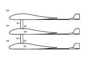
- FIG. 7 schematically shows an example of the flying body 100, the flying body 200, and the flying body 300 that are vertically combined.
- the aircraft 100 includes an upper surface side attachment / detachment section 160 arranged on the upper surface side of the aircraft 100.
- the aircraft 200 includes an upper surface side attachment / detachment portion 260 arranged on the upper surface side of the aircraft 200 and a connecting portion 264 arranged on the lower surface side of the aircraft 200.
- the connection portion 264 may be retractable on the lower surface side of the aircraft 200.
- the lower surface side attachment / detachment portion 262 is arranged at the tip of the connection portion 264.
- the aircraft 300 includes a connecting portion 364 arranged on the lower surface side of the aircraft 300.
- the connecting portion 364 may be housed on the lower surface side of the aircraft 300.
- the lower surface side attachment / detachment portion 362 is arranged at the tip of the connection portion 364.
- the upper surface side attachment / detachment section 160 may have a structural concave connection section, a positioning sensor, a signal connection section, and a power connection section, like the right wing side attachment / detachment section 140.
- the lower surface side attachment / detachment portion 262 may have a structural convex connection portion, a signal connection portion, and a power connection portion similarly to the left wing side attachment / detachment portion 230.
- the air vehicle 100 and the air vehicle 200 may be able to perform communication and power transmission via the upper surface side attachment / detachment section 160 and the lower surface side attachment / detachment section 262. Further, the aircraft 100 and the aircraft 200 may be able to execute fuel supply and demand via the upper surface side attachment / detachment section 160 and the lower surface side attachment / detachment section 262. As compared with the case where the attachment / detachment portion is arranged at the tip of the main wing 104 as shown in FIG.
- the contact area of the attachment / detachment portion can be increased by arranging the attachment / detachment portion on the upper surface or the lower surface, and thus the fuel can be discharged more quickly. Can be replenished.
- the case where the flying body 200 and the flying body 300 are combined may be the same as the case where the flying body 100 and the flying body 200 are combined.
- the air vehicle 100 may include a connection unit (not shown) arranged on the lower surface side of the air vehicle 100.
- the lower surface side attachment / detachment portion is arranged at the tip of the connection portion.
- the flying object 300 may include an upper surface side attaching / detaching portion (not shown) arranged on the upper surface side of the flying object 300.
- connection portion may be arranged on the upper surface side of the aircraft.
- connecting portions may be arranged on both the upper surface side and the lower surface side of the aircraft.
- the upper flight body and the lower flight body are united and separated by attaching and detaching the lower flight side connection section of the upper flight body and the upper flight side connection section of the lower flight body.
- the air vehicle 100, the air vehicle 200, and the air vehicle 300 may share communication partners.
- the flying body 100 may communicate with the ground
- the flying body 200 may wirelessly communicate with another flying body
- the flying body 300 may communicate with a communication satellite.
- the flying object 100, the flying object 200, and the flying object 300 can communicate with the communication partner without being interfered with each other.
- the flying body 100 may not have the function of wirelessly communicating with another flying body and the function of communicating with a communication satellite.
- the air vehicle 200 may not have a function of communicating with the ground and a function of communicating with a communication satellite.
- the air vehicle 300 may not have a function of communicating with the ground and a function of wirelessly communicating with another air vehicle.
- FIG. 8 schematically shows an example of a flying body 100, a flying body 200, and a flying body 300 that are united in an oblique direction.
- FIG. 7 differences from FIG. 7 will be mainly described.
- the connecting portion 264 projects from the lower surface side of the aircraft 200 toward the front of the aircraft 200.
- the connecting portion 364 projects from the lower surface side of the flying body 300 toward the front of the flying body 300. That is, when the connection portion is arranged on the lower surface side of the aircraft, the connection portion may project from the lower surface side of the aircraft toward the front of the aircraft. In addition, for example, when the connection portion is arranged on the upper surface side of the flight vehicle, the connection portion may project from the upper surface side of the flight vehicle toward the rear of the flight vehicle.
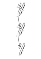
- FIG. 9 schematically shows an example of a flying body 100, a flying body 200, and a flying body 300 that are united in an oblique direction.
- FIG. 9 illustrates the case where the flying body 100, the flying body 200, and the flying body 300 are viewed from above.
- 310, the left wing side antenna 312, and the right wing side antenna 314 can be arranged two-dimensionally.
- the aircraft 100 includes a two-dimensionally arranged central antenna 110, left-wing antenna 112, right-wing antenna 114, central antenna 210, left-wing antenna 212, right-wing antenna 214, central antenna 310, left-wing antenna 312, and right-wing.
- Two-dimensional beamforming may be performed using the side antenna 314. As a result, the degree of freedom in forming the communication area can be increased and the directivity can be increased.
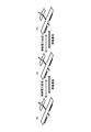
- FIG. 10 schematically shows an example of a flying body 100, a flying body 200, and a flying body 300 that are combined by a cable.
- the flying vehicle 100, the flying vehicle 200, and the flying vehicle 300 may be able to be combined via a cable.
- the flight vehicle 100 includes a cable 166 having an attachment / detachment section 168 that is physically attached / detached to / from another flight vehicle.
- the aircraft 200 includes a cable 266 having an attachment / detachment portion 268 that is physically attached / detached to / from another aircraft, and an upper surface side attachment / detachment portion 260 arranged on the upper surface side of the aircraft 200.
- the flying object 300 includes an upper surface side attaching / detaching part 360 arranged on the upper surface side of the flying object 300.
- the aircraft 100 may include an upper surface side attachment / detachment portion similar to the upper surface side attachment / detachment portion 260 of the aircraft 200.
- the air vehicle 300 may also include a cable similar to the cable 166 in the air vehicle 100.
- the flying body 200 is the main body, and the flying body 200 adjusts the positional relationship between the upper surface side attachment / detachment section 260 and the attachment / detachment section 168 to form the upper surface side attachment / detachment section.
- the 260 and the attaching / detaching part 168 may be connected.
- the aircraft 100 can store the cable 166 in a reel type, and after the aircraft 100 approaches the aircraft 200 in the stored state and the attaching / detaching portion 168 is connected to the upper surface side attaching / detaching portion 260, The attachment / detachment portion 168 and the upper surface-side attachment / detachment portion 260 may be connected such that 100 is separated from the flying object 200.
- the attaching / detaching portion 168 may have a structural concave connection portion, a positioning sensor, a signal connection portion, and a power connection portion.
- the upper surface side attachment / detachment portion 260 may have a structure convex connection portion, a signal connection portion, and a power connection portion similarly to the left wing side attachment / detachment portion 230.
- Aircraft 100 may have a cable communicator that communicates with aircraft 200 via cable 166.
- the aircraft 100 may include a power transmission unit that transmits power to and from the aircraft 200 via the cable 166.
- the aircraft 100 may also have a fuel supply / demand unit that supplies and receives fuel to / from the aircraft 200 via the cable 166.
- the case where the flying body 200 and the flying body 300 are combined may be the same as the case where the flying body 100 and the flying body 200 are combined.
- FIG. 11 schematically shows an example of a flying vehicle 100, a flying vehicle 200, and a flying vehicle 300 that are virtually combined.
- the flying body is virtually united does not mean that the flying body is physically united, but a state in which wireless communication and wireless power transmission are possible.
- the air vehicle 100, the air vehicle 200, and the air vehicle 300 each have a wireless communication unit that wirelessly communicates with another aircraft, and power transmission that performs wireless power transmission with the other aircraft. And an execution unit.
- the wireless communication unit may perform wireless communication by a communication method used for so-called V2V.
- the wireless communication unit performs wireless communication by beamforming.
- the power transmission execution unit may execute wireless power transmission by an arbitrary method such as an electromagnetic induction method.
- the air vehicle 100 has an interface capable of executing wireless communication with the wireless communication unit by the wireless communication unit and the power transmission execution unit, and having an interface capable of executing wireless power transmission with the power transmission execution unit. Virtually merge with another flight vehicle of the same or different type as 100. That is, the flight vehicle 100 can virtually combine with flight vehicles of different types as long as they have a common interface.
- the flying body 100 is virtually combined with the flying body 200, the flying body 300, and the like having a wireless communication unit and a power transmission execution unit, for example.
- the aircraft 100 has, for example, an interface that can perform wireless communication with a wireless communication unit included in the aircraft 100 and can perform wireless power transmission with the power transmission execution unit included in the aircraft 100. It is virtually combined with a balloon-type flying body, an airship-type flying body, a rotary-wing-type flying body, and the like. If such an interface becomes common and open, it will be possible to operate by virtually combining multiple aircraft as one aircraft without depending on the aircraft type of the aircraft and the manufacturer. It becomes possible to do. Further, by such virtual combination, it is possible to change the operation method for each of various formations. Integrated operation is possible with operation devices such as aircraft and communication services.
- FIG. 12 schematically shows an example of the functional configuration of the control device 400.
- the control device 400 includes a reception unit 402, a storage unit 403, a battery remaining amount acquisition unit 404, a power generation amount acquisition unit 406, a received light amount acquisition unit 408, a position information acquisition unit 410, a selection unit 414, and an aircraft control unit 416. . It is not essential that the control device 400 has all of these configurations.
- the receiving unit 402 receives information related to each situation of a plurality of air vehicles.
- the receiving unit 402 may receive, from each of the plurality of air vehicles, information related to the situation of each air vehicle.
- the reception unit 402 may receive, from any of the plurality of air vehicles, information collected from other air vehicles from the air vehicle.
- the receiving unit 402 may receive information related to each situation of the plurality of air vehicles from the management system 500.
- the information may include the configuration information of the air vehicle.
- the information may include functional information of the air vehicle.
- the information may include position information of the air vehicle.
- the information may include the remaining battery charge of the aircraft battery.
- the information may include the amount of power generated by the solar panel of the aircraft.
- the information may include the amount of light received by the solar cell panel of the aircraft.
- the storage unit 403 stores the information received by the reception unit 402.
- the battery remaining amount acquisition unit 404 acquires the battery remaining amount of each battery of a plurality of flying objects.
- the battery remaining amount acquisition unit 404 may acquire the battery remaining amount of each of the plurality of flying objects from the storage unit 403.
- the power generation amount acquisition unit 406 acquires the power generation amount of each of the plurality of air vehicles.
- the power generation amount acquisition unit 406 may acquire the power generation amount of each of the plurality of flying objects from the storage unit 403.
- the light reception amount acquisition unit 408 acquires the light reception amount of each of a plurality of flying objects.
- the received light amount acquisition unit 408 may acquire the received light amount of each of the plurality of flying objects from the storage unit 403.
- the position information acquisition unit 410 acquires position information of each of a plurality of air vehicles.
- the position information acquisition unit 410 may acquire the position information of each of the plurality of air vehicles from the storage unit 403.
- the selecting unit 414 selects a flight object that needs to be combined with another flight object from a plurality of flight objects.
- the selection unit 414 selects, for example, an air vehicle that satisfies a predetermined condition from among a plurality of air vehicles. Further, the selection unit 414 selects, from the plurality of flight vehicles, a flight vehicle to be merged with the selected flight vehicle.
- the selecting unit 414 selects, for example, of a plurality of flying bodies, a flying body closer to a flying body that needs to be combined.
- the selection unit 414 may select the aircraft to be combined according to the satisfied conditions.
- the selecting unit 414 selects, for example, an aircraft that needs to be united with an aircraft whose condition in the ground area covered by the communication area 150 satisfies a predetermined condition. For example, the selecting unit 414 selects a flying vehicle that has been flying in the super-rural area as a flying vehicle that needs to be united when moving to the rural area. Further, the selecting unit 414 selects, for example, a flying body that has been flying in the rural area as a flying body that needs to be united when moving to the urban area. In this case, the selection unit 414 selects, for example, an aircraft having a configuration similar to that of an aircraft that needs to be merged, as an aircraft to be merged. Further, the selection unit 414 selects, for example, a flying body that can provide a wireless communication service having a larger communication capacity than the wireless communication service of the flying body that needs to be combined, as a flying object to be combined.
- the selecting unit 414 selects, for example, a flying body that satisfies the predetermined communication condition of the communication area 150 to be formed, as a flying body that needs to be united.
- the condition is, for example, that the communication traffic in the communication area 150 is higher than a predetermined threshold value.
- the selection unit 414 selects, for example, an aircraft having a configuration similar to that of an aircraft that needs to be merged, as an aircraft to be merged.
- the selection unit 414 selects, for example, a flying body that can provide a wireless communication service having a larger communication capacity than the wireless communication service of the flying body that needs to be combined, as a flying object to be combined.
- the selecting unit 414 after combining the flight object that needs to be combined with the flight object to be combined, when the communication status of the communication area formed by the combined flight object satisfies a predetermined condition, You may further select the aircraft to be merged with the merged aircraft.
- the selecting unit 414 determines whether the communication traffic in the communication area 150 is between a predetermined first threshold value and a second threshold value higher than the first threshold value, and when the communication traffic is higher than the second threshold value. Then, the flying object to be combined may be different. For example, when the communication traffic in the communication area 150 is between the first threshold value and the second threshold value, the selection unit 414 selects an aircraft having a configuration similar to that of an aircraft that needs to be combined, When it is higher than the threshold value of 2, the aircraft which can provide the wireless communication service having the larger communication capacity than the wireless communication service by the aircraft which needs to be combined is selected.
- the selection unit 414 selects, for example, an aircraft having a battery remaining amount less than a predetermined threshold as an aircraft that needs to be combined.
- the selection unit 414 selects a flight vehicle that has a power supply unit that supplies power to another flight vehicle that has been combined as a flight object to be combined.
- the selecting unit 414 may include a power supply unit and may select, as a flying object to be combined, an flying object in which the battery remaining amount of the battery is larger than a predetermined threshold value.
- the selection unit 414 selects, for example, an aircraft whose power generation amount of the solar cell panel is less than a predetermined threshold as an aircraft that needs to be combined. In this case, the selection unit 414 selects a flight vehicle that has a power supply unit that supplies power to another flight vehicle that has been combined as a flight object to be combined.
- the selecting unit 414 may include a power supply unit and may select, as a flying object to be combined, an flying object in which the battery remaining amount of the battery is larger than a predetermined threshold value.
- the selection unit 414 selects, for example, an aircraft whose amount of light received by the solar cell panel is smaller than a predetermined threshold as an aircraft that needs to be combined. In this case, the selection unit 414 selects a flight vehicle that has a power supply unit that supplies power to another flight vehicle that has been combined as a flight object to be combined.
- the selecting unit 414 may include a power supply unit and may select, as a flying object to be combined, an flying object in which the battery remaining amount of the battery is larger than a predetermined threshold value.
- the selecting unit 414 selects, as a flying body that needs to be united, a flying body in which the weather condition of the flying area satisfies a predetermined condition.
- the condition is, for example, that the air velocity in the flight area is faster than a predetermined threshold value.
- the selection unit 414 selects a flight vehicle that is about to take off as a flight vehicle that needs to be united.
- the selection unit 414 selects, for example, an air vehicle having the same configuration as the air vehicle that needs to be united, as the air vehicle to be united.
- the selection unit 414 selects an aircraft having a propulsion mechanism that generates a stronger thrust than the propulsion mechanism mounted on the aircraft that needs to be united.
- the flight body control unit 416 controls the combination of the flight vehicle selected by the selection unit 414 that needs to be merged with the flight vehicle to be merged.
- the flying body control unit 416 may transmit a control signal including information of a joining partner and a joining instruction to any of the flying body that needs to be joined and the flying body to be joined.
- the flying body control unit 416 may transmit a control signal including information of a joining partner and a joining instruction to each of the flying body that needs to be joined and the flying body to be joined.
- the information of the coalescing partner may include identification information for identifying the flying body of the coalescing partner. Further, the information of the coalescing partner may include the position information of the flying body of the coalescing partner.
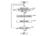
- FIG. 13 schematically shows an example of the flow of processing by the control device 400.
- a state in which the control device 400 monitors the states of a plurality of air vehicles will be described as a start state.
- step (the step may be abbreviated as S) 102 the selection unit 414 sets a predetermined condition for determining whether or not the plurality of air vehicles need to be combined. It is determined whether there is an air vehicle to satisfy. If it is determined that the file exists, the process proceeds to S104.
- the selection unit 414 selects a flight object to be combined with a flight object that needs to be combined according to the satisfied conditions.
- the flight control unit 416 transmits a control signal for combining the flight vehicle that needs to be merged with the flight vehicle that is the target to be merged to the flight vehicle that needs to be merged and the flight vehicle that is the target to be merged. As a result, it is possible to combine a flight object that needs to be merged with a flight object that is the target of the merger.
- S108 it is determined whether or not an end instruction to end the monitoring has been received. If it is determined that it has not been received, the process returns to S102, and if it is determined that it has been received, the processing ends.
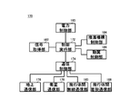
- FIG. 14 schematically shows an example of the functional configuration of the control device 170 included in the air vehicle 100.
- the control device 170 is arranged in the main body 102 of the aircraft 100, for example.
- the control device 170 includes a control execution unit 172, a communication control unit 174, a ground communication unit 176, a satellite communication unit 178, an inter-aircraft wireless communication unit 180, a signal acquisition unit 182, a propulsion mechanism control unit 184, a moving blade control unit 186, An inter-aircraft attachment / detachment communication unit 188 and a power control unit 190 are provided. Note that it is not essential that the control device 170 has all of these configurations.
- the control execution unit 172 executes various controls.
- the communication control unit 174 controls various types of communication.
- the control execution unit 172 controls communication by the ground communication unit 176, the satellite communication unit 178, the inter-flight body wireless communication unit 180, and the inter-flight body attachment / detachment communication unit 188.
- the ground communication unit 176 forms a communication area 150 on the ground and communicates with a communication device on the ground.
- the ground communication unit 176 communicates with the user terminal 30, for example.
- the ground communication unit 176 also communicates with the control device 400, for example.
- the ground communication unit 176 also communicates with the management system 500, for example.
- the satellite communication unit 178 communicates with a communication satellite.
- the satellite communication unit 178 communicates with the communication satellite using an antenna for communication with the communication satellite.
- the inter-aircraft wireless communication unit 180 wirelessly communicates with other aircraft.
- the inter-flight body wireless communication unit 180 wirelessly communicates with another flight object using an antenna for wireless communication with another flight object.
- the inter-aircraft wireless communication unit 180 forms a C2 link with another aircraft using the antenna, and communicates via the C2 link, for example.
- the inter-aircraft wireless communication unit 180 wirelessly communicates with another aircraft by performing beamforming on another aircraft using the antenna, for example.
- the signal acquisition unit 182 acquires the control signal transmitted by the control device 400.
- the signal acquisition unit 182 receives a control signal from the control device 400 via the ground communication unit 176, for example.
- the signal acquisition unit 182 may receive, via the satellite communication unit 178, the control signal transmitted by the control device 400 via the communication satellite 50.
- the signal acquisition unit 182 may acquire the control signal received by the other flying body from the control device 400 from the other flying body via the inter-aircraft wireless communication unit 180.
- the propulsion mechanism control unit 184 controls the propulsion mechanism.
- the propulsion mechanism control unit 184 controls, for example, the plurality of propellers 108.
- the moving blade control unit 186 controls the moving blades.
- the blade control unit 186 may control the blade 122.
- the blade control unit 186 may control the blade 124.
- the blade control unit 186 may control the blade 126.
- the control execution unit 172 may control the flight of the air vehicle 100 by causing the propulsion mechanism control unit 184 and the moving blade control unit 186 to control the propulsion mechanism and the moving blades. For example, when the signal acquisition unit 182 acquires the control signal, the control execution unit 172 causes the propulsion mechanism control unit 184 and the moving blade control unit 186 to control the propulsion mechanism and the moving blade based on the control signal. , Merge with the target flight vehicle.
- the inter-aircraft attachment / detachment communication unit 188 communicates with a united air vehicle.
- the inter-flight body attachment / detachment communication unit 188 communicates with the united flight body via the attachment / detachment unit.
- the electric power control unit 190 transmits electric power to the combined flying body.
- the power control unit 190 may control the power of the battery 120 to be supplied to the combined flying body via the attachment / detachment unit. Further, the power control unit 190 causes the battery 120 to store the power received from the combined flying body via the attaching / detaching unit.
- the aircraft 100 may be provided with a fuel supply / demand unit that performs fuel supply / demand with the combined aircraft, instead of the power control unit 190.
- the air vehicle 100 may include a fuel supply / demand unit as well as the power control unit 190.
- the fuel supply / demand unit may control the fuel in the fuel tank of the aircraft 100 to be supplied to the combined aircraft via the attachment / detachment unit.
- the fuel supply / demand unit may control the fuel received from the combined flying body via the attachment / detachment unit so as to be accumulated in the fuel tank included in the flying body 100.
- FIG. 15 schematically shows the flow of processing by the control execution unit 172.
- the flow of processing when the signal acquisition unit 182 receives a control signal from the control device 400 will be described.
- the control execution unit 172 determines whether or not the GPS signal of the flight object to be combined identified by the identification information of the flight object to be combined included in the control signal is received.
- the control execution unit 172 receives, for example, the GPS signal of the flight object to be combined from the control device 400, or the flight object to be combined from the flight object to be combined via the inter-aircraft wireless communication unit 180. If the GPS signal is received, it is determined that the GPS signal is received. If it is determined that it is received, the process proceeds to S204.
- control execution unit 172 controls the propulsion mechanism and the moving blades via the propulsion mechanism control unit 184 and the moving blade control unit 186, and moves to the side of the aircraft to be combined.
- control execution unit 172 determines whether or not the positioning sensor 144 can detect the flying object to be combined. If it can be detected, the process proceeds to S208, and if it cannot be detected, the process returns to S204.
- step S208 the control execution unit 172 controls the propulsion mechanism and the moving blades via the propulsion mechanism control unit 184 and the moving blade control unit 186, and connects the attachment / detachment portion of the aircraft 100 and the attachment / detachment portion of the aircraft to be combined. Connecting.
- the control execution unit 172 transmits a signal to the air vehicle to be combined via the inter-aircraft attachment / detachment communication unit 188.
- the control execution unit 172 determines whether or not an Ack signal is returned from the flying object to be combined. When the Ack signal is returned, the process proceeds to S214, and when it is not returned, the process returns to S208.
- control execution unit 172 completes the communication connection with the flight object to be combined.
- control execution unit 172 completes the electrical connection with the flying object to be combined.
- a relay may be arranged between the power connection unit 148 and the power control unit 190, and the control execution unit 172 may complete the power connection by short-circuiting the relay. Then, the process ends.
- FIG. 16 schematically shows an example of the computer 1000 that functions as the control device 400 or the control device 170.
- the computer 1000 according to the present embodiment includes a CPU peripheral unit having a CPU 1010, a RAM 1030, and a graphic controller 1085 that are mutually connected by a host controller 1092, a ROM 1020 that is connected to the host controller 1092 by an input / output controller 1094, and a communication I / O.
- An input / output unit including an F1040, a storage device 1050, and an input / output chip 1080 is provided.
- the CPU 1010 operates based on programs stored in the ROM 1020 and the RAM 1030, and controls each part.
- the graphic controller 1085 acquires image data generated by the CPU 1010 or the like on a frame buffer provided in the RAM 1030 and displays it on the display.
- the graphic controller 1085 may internally include a frame buffer that stores image data generated by the CPU 1010 or the like.
- the communication I / F 1040 communicates with other devices via a network by wire or wirelessly. Further, the communication I / F 1040 functions as hardware that performs communication.
- the storage device 1050 may be a hard disk drive, a solid state drive, or the like, and stores programs and data used by the CPU 1010.
- the ROM 1020 stores a boot program executed by the computer 1000 at startup and a program dependent on the hardware of the computer 1000.
- the input / output chip 1080 connects various input / output devices to the input / output controller 1094 via, for example, a USB port, a parallel port, a serial port, a keyboard port, a mouse port, and the like.
- the program provided to the storage device 1050 via the RAM 1030 is stored in a recording medium such as an IC card and provided by the user.
- the program is read from the recording medium, installed in the storage device 1050 via the RAM 1030, and executed by the CPU 1010.
- a program installed in the computer 1000 and causing the computer 1000 to function as the control device 400 or the control device 170 may act on the CPU 1010 or the like to cause the computer 1000 to function as each unit of the control device 400 or the control device 170, respectively.
- the information processing described in these programs is read by the computer 1000, and is a specific means in which software and the various hardware resources described above cooperate with each other, namely, the receiving unit 402, the storage unit 403, and the battery remaining. It functions as the amount acquisition unit 404, the power generation amount acquisition unit 406, the received light amount acquisition unit 408, the position information acquisition unit 410, the selection unit 414, and the flying body control unit 416.
- control execution unit 172 and the communication control unit which are concrete means in which software and the various hardware resources described above cooperate with each other.
- ground communication unit 176 satellite communication unit 178
- inter-flight body wireless communication unit 180 signal acquisition unit 182
- propulsion mechanism control unit 184 moving blade control unit 186
- inter-flight body attachment / detachment communication unit 188 power control unit 190.
Abstract
La présente invention concerne un corps volant comprenant : une antenne destinée à former une zone de communication terrestre et à fournir des services de communication sans fil à des terminaux d'utilisateur dans la zone de communication ; et une unité de fixation/détachement qui se fixe physiquement à un autre corps volant ou se détache de celui-ci afin de combiner ou de séparer les deux corps volants. La présente invention concerne également un corps volant comprenant : une antenne destinée à former une zone de communication terrestre et à fournir des services de communication sans fil à des terminaux d'utilisateur dans la zone de communication ; un câble qui a une unité de fixation/détachement qui se fixe physiquement à un autre corps volant ou se détache de celui-ci ; une unité de communication par câble qui communique avec l'autre corps volant par l'intermédiaire du câble ; et une unité de transmission d'énergie qui transmet de l'énergie depuis et vers l'autre corps volant par l'intermédiaire du câble.
Priority Applications (2)
| Application Number | Priority Date | Filing Date | Title |
|---|---|---|---|
| EP19872736.4A EP3868662B1 (fr) | 2018-10-15 | 2019-08-09 | Système et corps volant |
| US17/213,263 US11161607B2 (en) | 2018-10-15 | 2021-03-26 | Flying body and system |
Applications Claiming Priority (2)
| Application Number | Priority Date | Filing Date | Title |
|---|---|---|---|
| JP2018194686A JP6714668B2 (ja) | 2018-10-15 | 2018-10-15 | 飛行体及びシステム |
| JP2018-194686 | 2018-10-15 |
Related Child Applications (1)
| Application Number | Title | Priority Date | Filing Date |
|---|---|---|---|
| US17/213,263 Continuation US11161607B2 (en) | 2018-10-15 | 2021-03-26 | Flying body and system |
Publications (1)
| Publication Number | Publication Date |
|---|---|
| WO2020079935A1 true WO2020079935A1 (fr) | 2020-04-23 |
Family
ID=70283017
Family Applications (1)
| Application Number | Title | Priority Date | Filing Date |
|---|---|---|---|
| PCT/JP2019/031738 WO2020079935A1 (fr) | 2018-10-15 | 2019-08-09 | Système et corps volant |
Country Status (4)
| Country | Link |
|---|---|
| US (1) | US11161607B2 (fr) |
| EP (1) | EP3868662B1 (fr) |
| JP (1) | JP6714668B2 (fr) |
| WO (1) | WO2020079935A1 (fr) |
Cited By (2)
| Publication number | Priority date | Publication date | Assignee | Title |
|---|---|---|---|---|
| CN111951613A (zh) * | 2020-07-24 | 2020-11-17 | 北京航空航天大学 | 空地协同的广域空域安全态势评估方法 |
| US11137777B2 (en) * | 2018-10-15 | 2021-10-05 | Hapsmobile Inc. | Control apparatus, program, system and control method |
Families Citing this family (1)
| Publication number | Priority date | Publication date | Assignee | Title |
|---|---|---|---|---|
| JP7323244B1 (ja) | 2023-03-06 | 2023-08-08 | 株式会社三圓 | 浮上装置 |
Citations (7)
| Publication number | Priority date | Publication date | Assignee | Title |
|---|---|---|---|---|
| JP2002211496A (ja) | 2001-01-17 | 2002-07-31 | Honda Motor Co Ltd | 成層圏プラットフォーム |
| JP2004500786A (ja) * | 2000-04-10 | 2004-01-08 | エアロヴァイロンメント インコーポレイテッド | 通信システム |
| JP2010047109A (ja) * | 2008-08-21 | 2010-03-04 | Mitsubishi Heavy Ind Ltd | 無人機システム及びその運用方法 |
| US20100193625A1 (en) * | 2005-07-07 | 2010-08-05 | Sommer Geoffrey S | Modular articulated-wing aircraft |
| US20130037650A1 (en) * | 2011-03-15 | 2013-02-14 | Stephen B. Heppe | Systems and Methods for Long Endurance Airship Operations |
| US20160046387A1 (en) * | 2014-08-18 | 2016-02-18 | Sunlight Photonics Inc. | Methods and apparatus for a distributed airborne wireless communications fleet |
| JP2018505094A (ja) * | 2015-02-19 | 2018-02-22 | アマゾン テクノロジーズ インコーポレイテッド | 集合型無人航空機の構成 |
Family Cites Families (5)
| Publication number | Priority date | Publication date | Assignee | Title |
|---|---|---|---|---|
| EP2978258B1 (fr) * | 2014-07-22 | 2017-03-08 | Alcatel Lucent | Remplacement d'une première station de base drone par une seconde station drone sans interruption de service |
| US10303186B2 (en) * | 2016-03-29 | 2019-05-28 | Chengwen Chris WANG | Unmanned spatial vehicle performance |
| US20170297445A1 (en) * | 2016-04-19 | 2017-10-19 | Shenzhen Flyeah Intelligent Technology Co., Ltd. | Cone Shaped Docking Mechanism Provides Rigid Connection Between 2 UAVs and Serves as Charging Port to Provide Real Time Charging Power in the air as well as Serves as Ground UAV Charging Stations |
| US10059428B2 (en) * | 2016-08-10 | 2018-08-28 | Bell Helicopter Textron Inc. | Inflight connection of aircraft |
| US10189565B2 (en) * | 2016-12-02 | 2019-01-29 | The United States Of America As Represented By The Administrator Of The National Aeronautics And Space Administration | Modular unmanned aerial system with multi-mode propulsion |
-
2018
- 2018-10-15 JP JP2018194686A patent/JP6714668B2/ja active Active
-
2019
- 2019-08-09 EP EP19872736.4A patent/EP3868662B1/fr active Active
- 2019-08-09 WO PCT/JP2019/031738 patent/WO2020079935A1/fr unknown
-
2021
- 2021-03-26 US US17/213,263 patent/US11161607B2/en active Active
Patent Citations (7)
| Publication number | Priority date | Publication date | Assignee | Title |
|---|---|---|---|---|
| JP2004500786A (ja) * | 2000-04-10 | 2004-01-08 | エアロヴァイロンメント インコーポレイテッド | 通信システム |
| JP2002211496A (ja) | 2001-01-17 | 2002-07-31 | Honda Motor Co Ltd | 成層圏プラットフォーム |
| US20100193625A1 (en) * | 2005-07-07 | 2010-08-05 | Sommer Geoffrey S | Modular articulated-wing aircraft |
| JP2010047109A (ja) * | 2008-08-21 | 2010-03-04 | Mitsubishi Heavy Ind Ltd | 無人機システム及びその運用方法 |
| US20130037650A1 (en) * | 2011-03-15 | 2013-02-14 | Stephen B. Heppe | Systems and Methods for Long Endurance Airship Operations |
| US20160046387A1 (en) * | 2014-08-18 | 2016-02-18 | Sunlight Photonics Inc. | Methods and apparatus for a distributed airborne wireless communications fleet |
| JP2018505094A (ja) * | 2015-02-19 | 2018-02-22 | アマゾン テクノロジーズ インコーポレイテッド | 集合型無人航空機の構成 |
Non-Patent Citations (1)
| Title |
|---|
| See also references of EP3868662A4 |
Cited By (2)
| Publication number | Priority date | Publication date | Assignee | Title |
|---|---|---|---|---|
| US11137777B2 (en) * | 2018-10-15 | 2021-10-05 | Hapsmobile Inc. | Control apparatus, program, system and control method |
| CN111951613A (zh) * | 2020-07-24 | 2020-11-17 | 北京航空航天大学 | 空地协同的广域空域安全态势评估方法 |
Also Published As
| Publication number | Publication date |
|---|---|
| US11161607B2 (en) | 2021-11-02 |
| US20210237865A1 (en) | 2021-08-05 |
| EP3868662A1 (fr) | 2021-08-25 |
| EP3868662A4 (fr) | 2021-12-01 |
| JP2020062918A (ja) | 2020-04-23 |
| EP3868662B1 (fr) | 2022-09-21 |
| JP6714668B2 (ja) | 2020-06-24 |
Similar Documents
| Publication | Publication Date | Title |
|---|---|---|
| US11161607B2 (en) | Flying body and system | |
| US11492106B2 (en) | Vertical take-off and landing vehicle | |
| EP3243749B1 (fr) | Véhicule aérien sans pilote (uav) à capacité de décollage et d'atterrissage verticaux (adav) | |
| US10723456B2 (en) | Unmanned aerial vehicle system having multi-rotor type rotary wing | |
| EP3188476A1 (fr) | Réseau d'uav | |
| US11137777B2 (en) | Control apparatus, program, system and control method | |
| JP2018177135A (ja) | ドローンシェアリングサービス・プラットフォーム | |
| US11923954B1 (en) | Distributing wireless relays to form an ad hoc wireless network | |
| WO2020027140A1 (fr) | Système, dispositif de commande et aéronef léger | |
| US11120696B2 (en) | Control device, program, control method, and flight vehicle | |
| US11914362B2 (en) | Navigation system with camera assist | |
| US20210050911A1 (en) | Network for enabling beyond visual line of sight aircraft command and control communications | |
| JP6804494B2 (ja) | 飛行体 | |
| CN111158290B (zh) | 用于无人设备的多模态控制方法和装置 | |
| CN113283060A (zh) | 一种垂直起降固定翼无人机多机场择优起降方法 | |
| CN111061297A (zh) | 一种飞行控制计算机系统 | |
| CN218806707U (zh) | 一种救援固定翼无人机系统 | |
| CN116015421B (zh) | 无人机机载设备通信方法及装置 | |
| WO2021106287A1 (fr) | Système, dispositif de commande de communication, programme et procédé de commande | |
| KR20190094780A (ko) | 변형가능한 무인항공기 | |
| CN214690187U (zh) | 一种消防无人机 | |
| WO2023089735A1 (fr) | Objet volant comprenant un dispositif de sécurité | |
| CN110134141A (zh) | 一种垂直起降固定翼自动控制无人机系统 | |
| CN117002756A (zh) | 一种用于电力巡检的山火智能检测无人机装置及控制系统 | |
| CN116080911A (zh) | 一种基于太阳能无人机的临近空间持久驻留无人系统 |
Legal Events
| Date | Code | Title | Description |
|---|---|---|---|
| 121 | Ep: the epo has been informed by wipo that ep was designated in this application |
Ref document number: 19872736 Country of ref document: EP Kind code of ref document: A1 |
|
| NENP | Non-entry into the national phase |
Ref country code: DE |
|
| ENP | Entry into the national phase |
Ref document number: 2019872736 Country of ref document: EP Effective date: 20210517 |