WO2020079935A1 - Flying body and system - Google Patents
Flying body and system Download PDFInfo
- Publication number
- WO2020079935A1 WO2020079935A1 PCT/JP2019/031738 JP2019031738W WO2020079935A1 WO 2020079935 A1 WO2020079935 A1 WO 2020079935A1 JP 2019031738 W JP2019031738 W JP 2019031738W WO 2020079935 A1 WO2020079935 A1 WO 2020079935A1
- Authority
- WO
- WIPO (PCT)
- Prior art keywords
- aircraft
- unit
- antenna
- flying body
- attachment
- Prior art date
Links
- 238000004891 communication Methods 0.000 claims abstract description 235
- 230000005540 biological transmission Effects 0.000 claims abstract description 27
- 239000000446 fuel Substances 0.000 claims description 29
- 230000007246 mechanism Effects 0.000 description 26
- 238000000034 method Methods 0.000 description 18
- 230000008569 process Effects 0.000 description 12
- 239000003381 stabilizer Substances 0.000 description 11
- 238000010248 power generation Methods 0.000 description 8
- 238000012545 processing Methods 0.000 description 7
- 239000005437 stratosphere Substances 0.000 description 4
- 238000012546 transfer Methods 0.000 description 4
- 230000002708 enhancing effect Effects 0.000 description 3
- 239000002828 fuel tank Substances 0.000 description 3
- RZVHIXYEVGDQDX-UHFFFAOYSA-N 9,10-anthraquinone Chemical group C1=CC=C2C(=O)C3=CC=CC=C3C(=O)C2=C1 RZVHIXYEVGDQDX-UHFFFAOYSA-N 0.000 description 2
- 230000008859 change Effects 0.000 description 2
- 230000010365 information processing Effects 0.000 description 2
- 230000001502 supplementing effect Effects 0.000 description 2
- UFHFLCQGNIYNRP-UHFFFAOYSA-N Hydrogen Chemical compound [H][H] UFHFLCQGNIYNRP-UHFFFAOYSA-N 0.000 description 1
- 238000013459 approach Methods 0.000 description 1
- 230000015572 biosynthetic process Effects 0.000 description 1
- 230000007423 decrease Effects 0.000 description 1
- 230000001419 dependent effect Effects 0.000 description 1
- 230000005674 electromagnetic induction Effects 0.000 description 1
- 238000005516 engineering process Methods 0.000 description 1
- 238000005755 formation reaction Methods 0.000 description 1
- 239000003502 gasoline Substances 0.000 description 1
- 239000001257 hydrogen Substances 0.000 description 1
- 229910052739 hydrogen Inorganic materials 0.000 description 1
- 230000007774 longterm Effects 0.000 description 1
- 238000012986 modification Methods 0.000 description 1
- 230000004048 modification Effects 0.000 description 1
- 238000012544 monitoring process Methods 0.000 description 1
- 230000002093 peripheral effect Effects 0.000 description 1
- 239000007787 solid Substances 0.000 description 1
Images


Classifications
-
- H—ELECTRICITY
- H04—ELECTRIC COMMUNICATION TECHNIQUE
- H04B—TRANSMISSION
- H04B7/00—Radio transmission systems, i.e. using radiation field
- H04B7/14—Relay systems
- H04B7/15—Active relay systems
- H04B7/185—Space-based or airborne stations; Stations for satellite systems
- H04B7/18502—Airborne stations
- H04B7/18504—Aircraft used as relay or high altitude atmospheric platform
-
- B—PERFORMING OPERATIONS; TRANSPORTING
- B64—AIRCRAFT; AVIATION; COSMONAUTICS
- B64C—AEROPLANES; HELICOPTERS
- B64C1/00—Fuselages; Constructional features common to fuselages, wings, stabilising surfaces or the like
- B64C1/36—Fuselages; Constructional features common to fuselages, wings, stabilising surfaces or the like adapted to receive antennas or radomes
-
- B—PERFORMING OPERATIONS; TRANSPORTING
- B64—AIRCRAFT; AVIATION; COSMONAUTICS
- B64C—AEROPLANES; HELICOPTERS
- B64C37/00—Convertible aircraft
- B64C37/02—Flying units formed by separate aircraft
-
- B—PERFORMING OPERATIONS; TRANSPORTING
- B64—AIRCRAFT; AVIATION; COSMONAUTICS
- B64D—EQUIPMENT FOR FITTING IN OR TO AIRCRAFT; FLIGHT SUITS; PARACHUTES; ARRANGEMENTS OR MOUNTING OF POWER PLANTS OR PROPULSION TRANSMISSIONS IN AIRCRAFT
- B64D27/00—Arrangement or mounting of power plant in aircraft; Aircraft characterised thereby
- B64D27/02—Aircraft characterised by the type or position of power plant
- B64D27/24—Aircraft characterised by the type or position of power plant using steam, electricity, or spring force
-
- B—PERFORMING OPERATIONS; TRANSPORTING
- B64—AIRCRAFT; AVIATION; COSMONAUTICS
- B64D—EQUIPMENT FOR FITTING IN OR TO AIRCRAFT; FLIGHT SUITS; PARACHUTES; ARRANGEMENTS OR MOUNTING OF POWER PLANTS OR PROPULSION TRANSMISSIONS IN AIRCRAFT
- B64D39/00—Refuelling during flight
-
- B—PERFORMING OPERATIONS; TRANSPORTING
- B64—AIRCRAFT; AVIATION; COSMONAUTICS
- B64D—EQUIPMENT FOR FITTING IN OR TO AIRCRAFT; FLIGHT SUITS; PARACHUTES; ARRANGEMENTS OR MOUNTING OF POWER PLANTS OR PROPULSION TRANSMISSIONS IN AIRCRAFT
- B64D39/00—Refuelling during flight
- B64D39/06—Connecting hose to aircraft; Disconnecting hose therefrom
-
- G—PHYSICS
- G08—SIGNALLING
- G08G—TRAFFIC CONTROL SYSTEMS
- G08G5/00—Traffic control systems for aircraft, e.g. air-traffic control [ATC]
- G08G5/0004—Transmission of traffic-related information to or from an aircraft
- G08G5/0013—Transmission of traffic-related information to or from an aircraft with a ground station
-
- G—PHYSICS
- G08—SIGNALLING
- G08G—TRAFFIC CONTROL SYSTEMS
- G08G5/00—Traffic control systems for aircraft, e.g. air-traffic control [ATC]
- G08G5/0017—Arrangements for implementing traffic-related aircraft activities, e.g. arrangements for generating, displaying, acquiring or managing traffic information
- G08G5/0021—Arrangements for implementing traffic-related aircraft activities, e.g. arrangements for generating, displaying, acquiring or managing traffic information located in the aircraft
-
- G—PHYSICS
- G08—SIGNALLING
- G08G—TRAFFIC CONTROL SYSTEMS
- G08G5/00—Traffic control systems for aircraft, e.g. air-traffic control [ATC]
- G08G5/0043—Traffic management of multiple aircrafts from the ground
-
- G—PHYSICS
- G08—SIGNALLING
- G08G—TRAFFIC CONTROL SYSTEMS
- G08G5/00—Traffic control systems for aircraft, e.g. air-traffic control [ATC]
- G08G5/0047—Navigation or guidance aids for a single aircraft
- G08G5/0069—Navigation or guidance aids for a single aircraft specially adapted for an unmanned aircraft
-
- H—ELECTRICITY
- H01—ELECTRIC ELEMENTS
- H01Q—ANTENNAS, i.e. RADIO AERIALS
- H01Q1/00—Details of, or arrangements associated with, antennas
- H01Q1/27—Adaptation for use in or on movable bodies
- H01Q1/28—Adaptation for use in or on aircraft, missiles, satellites, or balloons
- H01Q1/286—Adaptation for use in or on aircraft, missiles, satellites, or balloons substantially flush mounted with the skin of the craft
- H01Q1/287—Adaptation for use in or on aircraft, missiles, satellites, or balloons substantially flush mounted with the skin of the craft integrated in a wing or a stabiliser
-
- H—ELECTRICITY
- H04—ELECTRIC COMMUNICATION TECHNIQUE
- H04B—TRANSMISSION
- H04B7/00—Radio transmission systems, i.e. using radiation field
- H04B7/14—Relay systems
- H04B7/15—Active relay systems
- H04B7/185—Space-based or airborne stations; Stations for satellite systems
-
- H—ELECTRICITY
- H04—ELECTRIC COMMUNICATION TECHNIQUE
- H04B—TRANSMISSION
- H04B7/00—Radio transmission systems, i.e. using radiation field
- H04B7/14—Relay systems
- H04B7/15—Active relay systems
- H04B7/185—Space-based or airborne stations; Stations for satellite systems
- H04B7/1851—Systems using a satellite or space-based relay
- H04B7/18515—Transmission equipment in satellites or space-based relays
-
- B—PERFORMING OPERATIONS; TRANSPORTING
- B64—AIRCRAFT; AVIATION; COSMONAUTICS
- B64C—AEROPLANES; HELICOPTERS
- B64C13/00—Control systems or transmitting systems for actuating flying-control surfaces, lift-increasing flaps, air brakes, or spoilers
- B64C13/02—Initiating means
- B64C13/16—Initiating means actuated automatically, e.g. responsive to gust detectors
- B64C13/20—Initiating means actuated automatically, e.g. responsive to gust detectors using radiated signals
-
- B—PERFORMING OPERATIONS; TRANSPORTING
- B64—AIRCRAFT; AVIATION; COSMONAUTICS
- B64D—EQUIPMENT FOR FITTING IN OR TO AIRCRAFT; FLIGHT SUITS; PARACHUTES; ARRANGEMENTS OR MOUNTING OF POWER PLANTS OR PROPULSION TRANSMISSIONS IN AIRCRAFT
- B64D2221/00—Electric power distribution systems onboard aircraft
-
- B—PERFORMING OPERATIONS; TRANSPORTING
- B64—AIRCRAFT; AVIATION; COSMONAUTICS
- B64U—UNMANNED AERIAL VEHICLES [UAV]; EQUIPMENT THEREFOR
- B64U10/00—Type of UAV
- B64U10/25—Fixed-wing aircraft
-
- B—PERFORMING OPERATIONS; TRANSPORTING
- B64—AIRCRAFT; AVIATION; COSMONAUTICS
- B64U—UNMANNED AERIAL VEHICLES [UAV]; EQUIPMENT THEREFOR
- B64U2101/00—UAVs specially adapted for particular uses or applications
- B64U2101/20—UAVs specially adapted for particular uses or applications for use as communications relays, e.g. high-altitude platforms
-
- B—PERFORMING OPERATIONS; TRANSPORTING
- B64—AIRCRAFT; AVIATION; COSMONAUTICS
- B64U—UNMANNED AERIAL VEHICLES [UAV]; EQUIPMENT THEREFOR
- B64U2201/00—UAVs characterised by their flight controls
- B64U2201/10—UAVs characterised by their flight controls autonomous, i.e. by navigating independently from ground or air stations, e.g. by using inertial navigation systems [INS]
- B64U2201/102—UAVs characterised by their flight controls autonomous, i.e. by navigating independently from ground or air stations, e.g. by using inertial navigation systems [INS] adapted for flying in formations
-
- B—PERFORMING OPERATIONS; TRANSPORTING
- B64—AIRCRAFT; AVIATION; COSMONAUTICS
- B64U—UNMANNED AERIAL VEHICLES [UAV]; EQUIPMENT THEREFOR
- B64U2201/00—UAVs characterised by their flight controls
- B64U2201/20—Remote controls
-
- B—PERFORMING OPERATIONS; TRANSPORTING
- B64—AIRCRAFT; AVIATION; COSMONAUTICS
- B64U—UNMANNED AERIAL VEHICLES [UAV]; EQUIPMENT THEREFOR
- B64U30/00—Means for producing lift; Empennages; Arrangements thereof
- B64U30/10—Wings
-
- B—PERFORMING OPERATIONS; TRANSPORTING
- B64—AIRCRAFT; AVIATION; COSMONAUTICS
- B64U—UNMANNED AERIAL VEHICLES [UAV]; EQUIPMENT THEREFOR
- B64U50/00—Propulsion; Power supply
- B64U50/10—Propulsion
- B64U50/13—Propulsion using external fans or propellers
-
- B—PERFORMING OPERATIONS; TRANSPORTING
- B64—AIRCRAFT; AVIATION; COSMONAUTICS
- B64U—UNMANNED AERIAL VEHICLES [UAV]; EQUIPMENT THEREFOR
- B64U50/00—Propulsion; Power supply
- B64U50/10—Propulsion
- B64U50/19—Propulsion using electrically powered motors
-
- B—PERFORMING OPERATIONS; TRANSPORTING
- B64—AIRCRAFT; AVIATION; COSMONAUTICS
- B64U—UNMANNED AERIAL VEHICLES [UAV]; EQUIPMENT THEREFOR
- B64U50/00—Propulsion; Power supply
- B64U50/30—Supply or distribution of electrical power
- B64U50/31—Supply or distribution of electrical power generated by photovoltaics
-
- H—ELECTRICITY
- H04—ELECTRIC COMMUNICATION TECHNIQUE
- H04B—TRANSMISSION
- H04B7/00—Radio transmission systems, i.e. using radiation field
- H04B7/14—Relay systems
- H04B7/15—Active relay systems
- H04B7/185—Space-based or airborne stations; Stations for satellite systems
- H04B7/18502—Airborne stations
-
- H—ELECTRICITY
- H04—ELECTRIC COMMUNICATION TECHNIQUE
- H04W—WIRELESS COMMUNICATION NETWORKS
- H04W16/00—Network planning, e.g. coverage or traffic planning tools; Network deployment, e.g. resource partitioning or cells structures
- H04W16/24—Cell structures
- H04W16/28—Cell structures using beam steering
Abstract
Provided is a flying body comprising: an antenna for forming a terrestrial communication area and providing wireless communication services to user terminals in the communication area; and an attachment/detachment unit that physically attaches to or detaches from another flying body in order to combine the flying body with or separate same from the other flying body. Also provided is a flying body comprising: an antenna for forming a terrestrial communication area and providing wireless communication services to user terminals in the communication area; a cable that has an attachment/detachment unit that physically attaches to or detaches from another flying body; a cable communication unit that communicates with the other flying body via the cable; and a power transmission unit that transmits power to and from the other flying body via the cable.
Description
本発明は、飛行体及びシステムに関する。
The present invention relates to an aircraft and a system.
成層圏プラットフォームを提供すべく、アンテナを有し、成層圏を飛行する飛行体が知られていた(例えば、特許文献1参照)。
[先行技術文献]
[特許文献]
[特許文献1]特開2002-211496号公報 A flying body having an antenna and flying in the stratosphere in order to provide a stratospheric platform has been known (see, for example, Patent Document 1).
[Prior Art Document]
[Patent Document]
[Patent Document 1] Japanese Patent Laid-Open No. 2002-211496
状況に応じて飛行体の機能を変更可能な技術を提供することが望ましい。
▽ It is desirable to provide technology that can change the functions of the aircraft depending on the situation.
本発明の第1の態様によれば、飛行体が提供される。飛行体は、地上に向けて照射するビームによって通信エリアを形成して通信エリア内のユーザ端末に無線通信サービスを提供するためのアンテナを備えてよい。飛行体は、他の飛行体と合体分離すべく他の飛行体と物理的に着脱する着脱部を備えてよい。
According to the first aspect of the present invention, an air vehicle is provided. The air vehicle may include an antenna for forming a communication area by a beam emitted toward the ground and providing a wireless communication service to a user terminal in the communication area. The air vehicle may include an attachment / detachment section that is physically attached to and detached from another air vehicle so as to be united and separated from the other air vehicle.
上記飛行体は、上記飛行体及び上記他の飛行体が飛行中に、上記着脱部と上記他の飛行体が備える着脱部とを接続するように上記飛行体を制御する制御実行部を備えてよい。上記飛行体は、上記着脱部を介して、上記他の飛行体と通信する着脱通信部を備えてよい。上記飛行体は、上記着脱部を介して、上記他の飛行体との間で電力を伝送する電力伝送部を備えてよい。上記飛行体は、上記着脱部を介して、上記他の飛行体との間で燃料を需給する燃料需給部を備えてよい。上記着脱部は、上記飛行体が有する主翼の右翼側に配置された右翼側着脱部と、上記主翼の左翼側に配置された左翼側着脱部とを含んでよい。上記着脱部は、上記飛行体の上面側に配置された上面側着脱部と、上記飛行体の下面側に配置された下面側着脱部との少なくともいずれかをさらに含んでよい。上記着脱部は、上記飛行体の上面側に配置された上面側着脱部と、上記飛行体の下面側に配置された下面側着脱部との少なくともいずれかを含んでよい。上記上面側着脱部は、上記飛行体の上面から上記飛行体の後方に向けて突き出す接続部に配置されていてよく、上記下面側着脱部は、上記飛行体の下面から上記飛行体の前方に向けて突き出す接続部に配置されていてよい。
The flight vehicle includes a control execution unit that controls the flight vehicle such that the attachment / detachment section and the attachment / detachment section included in the other flight vehicle are connected while the flight vehicle and the other flight vehicle are in flight. Good. The aircraft may include an attachment / detachment communication unit that communicates with the another aircraft via the attachment / detachment unit. The flight vehicle may include a power transmission unit that transmits power to the other flight vehicle via the attachment / detachment unit. The aircraft may include a fuel supply / demand unit that supplies and receives fuel to / from the other aircraft via the attachment / detachment unit. The attachment / detachment portion may include a right wing side attachment / detachment portion arranged on the right wing side of the main wing of the aircraft and a left wing side attachment / detachment portion arranged on the left wing side of the main wing. The attachment / detachment section may further include at least one of an upper surface side attachment / detachment section arranged on the upper surface side of the flight vehicle and a lower surface side attachment / detachment section arranged on the lower surface side of the flight vehicle. The attachment / detachment section may include at least one of an upper surface side attachment / detachment section arranged on the upper surface side of the flight vehicle and a lower surface side attachment / detachment section arranged on the lower surface side of the flight vehicle. The upper surface side attachment / detachment portion may be arranged at a connection portion protruding from the upper surface of the aircraft to the rear of the aircraft, and the lower surface side attachment / detachment portion may be arranged from the lower surface of the aircraft to the front of the aircraft. It may be arranged at the connecting part projecting towards it.
上記アンテナは、上記飛行体の主翼の中央に配置された第1中央アンテナと、上記飛行体の主翼の左翼に配置された第1左翼側アンテナと、上記飛行体の主翼の右翼に配置された第1右翼側アンテナとを含んでよく、上記他の飛行体は、上記他の飛行体の主翼の中央に配置された第2中央アンテナと、上記他の飛行体の主翼の左翼に配置された第2左翼側アンテナと、上記他の飛行体の主翼の右翼に配置された第2右翼側アンテナとを含んでよい。上記飛行体は、上記アンテナを用いて地上に上記通信エリアを形成する地上通信部を備えてよく、上記地上通信部は、上記第1中央アンテナ、上記第1左翼側アンテナ、上記第1右翼側アンテナ、上記第2中央アンテナ、上記第2左翼側アンテナ、及び上記第2右翼側アンテナによるビームフォーミングによって、上記通信エリアを形成するよう制御してよい。
The antenna is a first central antenna arranged in the center of the main wing of the aircraft, a first left-wing antenna arranged in the left wing of the main wing of the aircraft, and a right wing of the main wing of the aircraft. A second central antenna disposed in the center of the main wing of the other flight vehicle, and a left wing of the main wing of the other flight vehicle. The second left-wing side antenna and the second right-wing side antenna arranged on the right wing of the main wing of the other flying body may be included. The air vehicle may include a ground communication unit that forms the communication area on the ground using the antenna, and the ground communication unit includes the first central antenna, the first left wing side antenna, and the first right wing side. Beamforming by an antenna, the second central antenna, the second left-side antenna, and the second right-side antenna may be controlled to form the communication area.
本発明の第2の態様によれば、システムが提供される。システムは、第1の飛行体、第2の飛行体、及び第3の飛行体を備えてよい。第1の飛行体は、地上の通信装置と通信するためのアンテナと、第1の飛行体の上面に配置され、第2の飛行体の下面に配置された下面着脱部と物理的に着脱する着脱部と、着脱部を介して第2の飛行体と通信する着脱通信部とを有してよい。第2の飛行体は、第1の飛行体及び第3の飛行体以外の他の飛行体と通信するためのアンテナと、第2の飛行体の下面に配置された下面着脱部と、第2の飛行体の上面に配置され、第3の飛行体の下面に配置された下面着脱部と物理的に着脱する上面着脱部と、下面着脱部を介して第2の飛行体と通信し、上面着脱部を介して第3の飛行体と通信する着脱通信部とを有してよい。第3の飛行体は、通信衛星と通信するためのアンテナと、第3の飛行体の下面に配置された下面着脱部と、下面着脱部を介して第2の飛行体と通信する着脱通信部とを有してよい。第1の飛行体は、第2の飛行体を介して他の飛行体と通信し、第3の飛行体を介して通信衛星と通信してよい。
According to the second aspect of the present invention, a system is provided. The system may include a first air vehicle, a second air vehicle, and a third air vehicle. The first flying body is physically attached to and detached from an antenna for communicating with a ground communication device and a lower surface attaching / detaching portion arranged on the upper surface of the first flying body and on the lower surface of the second flying body. It may have an attachment / detachment section and an attachment / detachment communication section that communicates with the second aircraft via the attachment / detachment section. The second flight vehicle includes an antenna for communicating with other flight vehicles other than the first flight vehicle and the third flight vehicle, a lower surface attachment / detachment section arranged on a lower surface of the second flight vehicle, and a second flight vehicle. The upper surface attaching / detaching portion arranged on the upper surface of the aircraft and physically attached to / detaching the lower surface attaching / detaching portion arranged on the lower surface of the third aircraft, and communicating with the second aircraft via the lower surface attaching / detaching portion, A detachable communication unit that communicates with the third flying object via the detachable unit may be included. The third flying body has an antenna for communicating with a communication satellite, a lower surface attaching / detaching section arranged on a lower surface of the third flying body, and a detachable communication section for communicating with the second flying body via the lower surface attaching / detaching section. May have and. The first air vehicle may communicate with other air vehicles via the second air vehicle and the communication satellites via the third air vehicle.
本発明の第3の態様によれば、飛行体が提供される。飛行体は、地上に向けて照射するビームによって通信エリアを形成して通信エリア内のユーザ端末に無線通信サービスを提供するためのアンテナを備えてよい。飛行体は、他の飛行体と物理的に着脱する着脱部を有するケーブルを備えてよい。飛行体は、ケーブルを介して他の飛行体と通信するケーブル通信部を備えてよい。飛行体は、ケーブルを介して他の飛行体との間で電力を伝送する電力伝送部を備えてよい。飛行体は、他の飛行体が備えるケーブルが有する着脱部と物理的に着脱する着脱部を備えてよい。
According to the third aspect of the present invention, an air vehicle is provided. The air vehicle may include an antenna for forming a communication area by a beam emitted toward the ground and providing a wireless communication service to a user terminal in the communication area. The air vehicle may include a cable having an attachment / detachment portion that is physically attached to and detached from another air vehicle. The air vehicle may include a cable communication unit that communicates with other air vehicles via a cable. The air vehicle may include a power transfer unit that transfers power to and from another air vehicle via a cable. The flying body may include an attaching / detaching portion that physically attaches / detaches to / from an attaching / detaching portion included in a cable included in another flying body.
本発明の第4の態様によれば、飛行体が提供される。飛行体は、地上に向けて照射するビームによって通信エリアを形成して通信エリア内のユーザ端末に無線通信サービスを提供するためのアンテナを備えてよい。飛行体は、他の飛行体と無線通信する無線通信部を備えてよい。飛行体は、他の飛行体との間で無線電力伝送を実行する電力伝送実行部を備えてよい。飛行体は、無線通信部及び電力伝送実行部によって、無線通信部と無線通信を実行可能であり、かつ、電力伝送実行部との間で無線電力伝送を実行可能なインターフェースを有する、飛行体と同一又は異なる種類の他の飛行体と仮想的に合体してよい。
According to the fourth aspect of the present invention, an air vehicle is provided. The air vehicle may include an antenna for forming a communication area by a beam emitted toward the ground and providing a wireless communication service to a user terminal in the communication area. The air vehicle may include a wireless communication unit that wirelessly communicates with other air vehicles. The air vehicle may include a power transfer execution unit that performs wireless power transfer with another air vehicle. The aircraft has an interface capable of performing wireless communication with the wireless communication unit by the wireless communication unit and the power transmission execution unit, and having an interface capable of performing wireless power transmission with the power transmission execution unit. It may be virtually combined with other air vehicles of the same or different types.
なお、上記の発明の概要は、本発明の必要な特徴の全てを列挙したものではない。また、これらの特徴群のサブコンビネーションもまた、発明となりうる。
The above summary of the invention does not enumerate all necessary features of the invention. Further, a sub-combination of these feature groups can also be an invention.
以下、発明の実施の形態を通じて本発明を説明するが、以下の実施形態は請求の範囲にかかる発明を限定するものではない。また、実施形態の中で説明されている特徴の組み合わせの全てが発明の解決手段に必須であるとは限らない。
Hereinafter, the present invention will be described through embodiments of the invention, but the following embodiments do not limit the invention according to the claims. In addition, not all of the combinations of features described in the embodiments are essential to the solving means of the invention.
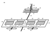
図1は、本実施形態に係るシステム10の一例を概略的に示す。システム10は、複数の飛行体を備える。また、システム10は、制御装置400を備える。図1では、複数の飛行体として、飛行体100、飛行体200及び飛行体300を例示している。複数の飛行体は、飛行体100、飛行体200及び飛行体300以外の飛行体を含んでもよい。
FIG. 1 schematically shows an example of a system 10 according to this embodiment. The system 10 comprises a plurality of air vehicles. The system 10 also includes a control device 400. In FIG. 1, a flying body 100, a flying body 200, and a flying body 300 are illustrated as the plurality of flying bodies. The plurality of air vehicles may include air vehicles other than the air vehicle 100, the air vehicle 200, and the air vehicle 300.
飛行体100は、地上に向けて照射するビームによって通信エリア150を形成して、通信エリア150内のユーザ端末30に無線通信サービスを提供する。通信エリア150は地上に形成されてよく、飛行体100は、通信エリア150によって、地上のユーザ端末30に無線通信サービスを提供してよい。また、通信エリア150は、上空も対象とする、3次元通信エリアであってもよい。通信エリア150が3次元通信エリアである場合、飛行体100は、上空に位置するドローン等のユーザ端末30に対しても無線通信サービスを提供してよい。飛行体100は、例えば、成層圏を巡回して、ユーザ端末30に無線通信サービスを提供する。飛行体100は、成層圏プラットフォームとして機能してよい。
The air vehicle 100 forms a communication area 150 by a beam emitted toward the ground and provides a wireless communication service to the user terminal 30 in the communication area 150. The communication area 150 may be formed on the ground, and the air vehicle 100 may provide the wireless communication service to the user terminal 30 on the ground by the communication area 150. The communication area 150 may also be a three-dimensional communication area that targets the sky. When the communication area 150 is a three-dimensional communication area, the flying object 100 may provide the wireless communication service to the user terminal 30 such as a drone located in the sky. The air vehicle 100 patrols the stratosphere, for example, and provides a wireless communication service to the user terminal 30. Aircraft 100 may function as a stratosphere platform.
ユーザ端末30は、飛行体100と通信可能な通信端末であればどのような端末であってもよい。例えば、ユーザ端末30は、スマートフォン等の携帯電話である。ユーザ端末30は、タブレット端末及びPC(Personal Computer)等であってもよい。ユーザ端末30は、いわゆるIoT(Internet of Thing)デバイスであってもよい。IoTデバイスとしては、各種センサ及び各種アクチュエータ等が例示できる。ユーザ端末30は、車両、船舶及びドローン等に搭載された通信モジュールであってもよい。ユーザ端末30は、いわゆるIoE(Internet of Everything)に該当するあらゆるものを含み得る。
The user terminal 30 may be any terminal as long as it can communicate with the flying object 100. For example, the user terminal 30 is a mobile phone such as a smartphone. The user terminal 30 may be a tablet terminal, a PC (Personal Computer), or the like. The user terminal 30 may be a so-called IoT (Internet of Thing) device. Examples of the IoT device include various sensors and various actuators. The user terminal 30 may be a communication module mounted on a vehicle, a ship, a drone or the like. The user terminal 30 may include anything corresponding to so-called IoE (Internet of Everything).
飛行体100は、太陽電池パネル及びバッテリを備えてよい。バッテリは、太陽電池パネルによって発電された電力を蓄電する。飛行体100は、バッテリに蓄電された電力によって、プロペラ等の推進機構を駆動させることによって飛行可能である。また、飛行体100は、バッテリに蓄電された電力によって、通信エリア150を形成してよい。
The air vehicle 100 may include a solar cell panel and a battery. The battery stores the electric power generated by the solar cell panel. The flying body 100 can fly by driving a propulsion mechanism such as a propeller with electric power stored in a battery. In addition, the air vehicle 100 may form the communication area 150 by the electric power stored in the battery.
飛行体100は、例えば、カバー対象の地上エリアの上空を巡回しながら、通信エリア150によって当該地上エリアをカバーする。飛行体100が地上エリアの上空を旋回することを定点飛行と記載する場合がある。また、飛行体100は、例えば、カバー対象の地上エリアの一部を通信エリア150によってカバーしながら、地上エリアの上空を移動することによって、地上エリアの全体をカバーする。
The air vehicle 100 covers the ground area by the communication area 150, for example, while traveling over the ground area to be covered. Turning the flying vehicle 100 over the ground area may be referred to as fixed point flight. Further, the air vehicle 100 covers the entire ground area by moving over the ground area while covering a part of the ground area to be covered by the communication area 150, for example.
飛行体100は、通信エリア150を形成するためのアンテナを有する。当該アンテナは、例えばマルチビームアンテナであってよい。通信エリア150は、複数のサブセル152によって構成されてよい。通信エリア150は、1つのセルによって構成されてもよい。
The air vehicle 100 has an antenna for forming a communication area 150. The antenna may be, for example, a multi-beam antenna. The communication area 150 may be composed of a plurality of subcells 152. The communication area 150 may be configured by one cell.
飛行体100は、例えば、ユーザ端末30と地上のネットワーク20との通信を中継することによって、ユーザ端末30に無線通信サービスを提供する。ネットワーク20は、任意のネットワークであってよく、例えば、インターネットと、いわゆる3G(3rd Generation)、LTE(Long Term Evolution)、4G(4th Generation)及び5G(5th Generation)等の携帯電話網と、公衆無線LAN(Local Area Network)と、専用網との少なくともいずれかを含んでよい。
The air vehicle 100 provides a wireless communication service to the user terminal 30 by relaying communication between the user terminal 30 and the ground network 20, for example. The network 20 may be any network, for example, the Internet, mobile phone networks such as so-called 3G (3rd Generation), LTE (Long Term Evolution), 4G (4th Generation) and 5G (5th Generation), and the public. It may include at least one of a wireless LAN (Local Area Network) and a dedicated network.
飛行体100は、例えば、地上の各地に配置されたゲートウェイ40のうち、通信エリア150内のゲートウェイ40を介して地上のネットワーク20と通信する。また、飛行体100は、例えば、通信衛星50を介して地上のネットワーク20と通信する。この場合、飛行体100は、通信衛星50と通信するためのアンテナを有する。
The air vehicle 100 communicates with the network 20 on the ground via the gateway 40 in the communication area 150 among the gateways 40 arranged in various places on the ground, for example. In addition, the air vehicle 100 communicates with the ground network 20 via the communication satellite 50, for example. In this case, the air vehicle 100 has an antenna for communicating with the communication satellite 50.
また、飛行体100は、他の飛行体と通信する。飛行体100は、例えば、ネットワーク20を介して、他の飛行体と通信する。また、飛行体100は、例えば、通信衛星50を介して他の飛行体と通信する。
Also, the air vehicle 100 communicates with other air vehicles. The air vehicle 100 communicates with other air vehicles via the network 20, for example. Further, the air vehicle 100 communicates with other air vehicles via the communication satellite 50, for example.
飛行体100は、他の飛行体と無線通信してもよい。飛行体100は、無線通信によって他の飛行体と直接通信してよい。この場合、飛行体100は、他の飛行体と無線通信するためのアンテナを有する。飛行体100は、例えば、当該アンテナを用いて他の飛行体との間でC2リンクを形成し、C2リンクを介して通信してよい。
The air vehicle 100 may wirelessly communicate with other air vehicles. Aircraft 100 may communicate directly with other air vehicles by wireless communication. In this case, the flying object 100 has an antenna for wireless communication with another flying object. The air vehicle 100 may form a C2 link with another air vehicle using the antenna, and may communicate via the C2 link, for example.
飛行体200は、飛行体100と同様の構成を有してよい。飛行体200は、飛行体100と一部異なる構成を有してもよい。例えば、飛行体200は、飛行体100による無線通信サービスよりも通信キャパシティが大きい無線通信サービスを提供可能であってよい。この場合、飛行体200は、飛行体100よりも大型であってよく、飛行体100のアンテナよりも大型のアンテナを搭載してよい。
The air vehicle 200 may have the same configuration as the air vehicle 100. The flying body 200 may have a partially different configuration from the flying body 100. For example, the air vehicle 200 may be capable of providing a wireless communication service having a larger communication capacity than the wireless communication service provided by the air vehicle 100. In this case, the flying vehicle 200 may be larger than the flying vehicle 100, and may have an antenna larger than the antenna of the flying vehicle 100.
また、例えば、飛行体200は、他の飛行体に電力を供給する電力供給部を有してよい。また、飛行体200は、例えば、飛行体100が搭載する推進機構よりも強い推力を発生する推進機構を有してよい。
Further, for example, the aircraft 200 may have a power supply unit that supplies power to other aircraft. In addition, the flying body 200 may include, for example, a propulsion mechanism that generates a stronger thrust than the propulsion mechanism mounted on the flying body 100.
飛行体300は、飛行体200と同じように、飛行体100と同様の構成を有してよい。また、飛行体300は、飛行体200と同じように、飛行体100と一部異なる構成を有してもよい。
The air vehicle 300 may have the same configuration as the air vehicle 100, like the air vehicle 200. The flying object 300 may have a configuration partially different from that of the flying object 100, like the flying object 200.
制御装置400は、複数の飛行体を制御する。制御装置400は、複数の飛行体のそれぞれに対して指示を送信することによって、複数の飛行体を制御する。制御装置400は、例えば、通信エリア150によって地上の通信エリアをカバーさせるべく、複数の飛行体を制御する。
The control device 400 controls a plurality of flying objects. The control device 400 controls the plurality of air vehicles by transmitting an instruction to each of the plurality of air vehicles. The control device 400 controls a plurality of air vehicles so that the communication area 150 covers the ground communication area, for example.
本実施形態に係る制御装置400は、複数の飛行体同士の合体を制御する。制御装置400は、例えば、複数の飛行体から、合体させる2以上の飛行体を選択して、選択した2以上の飛行体に対して制御信号を送信することによって、2以上の飛行体同士を合体させる。
The control device 400 according to the present embodiment controls the combination of a plurality of flying vehicles. The control device 400 selects, for example, two or more air vehicles to be combined from a plurality of air vehicles, and transmits a control signal to the selected two or more air vehicles, thereby connecting the two or more air vehicles to each other. To coalesce.
制御装置400は、例えば、複数の飛行体から、飛行体100と合体させる飛行体を選択して、選択した飛行体と飛行体100とを合体させるよう制御する。制御装置400は、例えば、飛行体100に関連する様々な状況を監視して、当該状況が予め定められた条件を満たした場合、満たした条件に応じて、飛行体100と合体させる飛行体を選択する。
The control device 400, for example, selects a flying body to be combined with the flying body 100 from a plurality of flying bodies, and controls to combine the selected flying body and the flying body 100. The control device 400 monitors, for example, various situations related to the aircraft 100, and when the situation satisfies a predetermined condition, the controller 400 determines the aircraft to be combined with the aircraft 100 according to the satisfied condition. select.
制御装置400は、例えば、飛行体100が提供する無線通信サービスにおける通信トラフィックが予め定められた閾値を超えた場合に、飛行体100と合体させる飛行体を選択する。制御装置400は、例えば、飛行体100と同様の構成を有する飛行体200を選択する。また、制御装置400は、例えば、飛行体100による無線通信サービスよりも通信キャパシティが大きい無線通信サービスを提供する飛行体200を選択する。制御装置400は、飛行体100と飛行体200とを合体させた後、飛行体100及び飛行体200による無線通信サービスにおける通信トラフィックが予め定められた閾値を超えた場合に、飛行体100及び飛行体200に対してさらに合体させる飛行体を選択してもよい。例えば、制御装置400は、飛行体100と同様の構成を有する飛行体300を選択する。また、制御装置400は、例えば、飛行体100による無線通信サービスよりも通信キャパシティが大きい無線通信サービスを提供可能な飛行体300を選択する。
The control device 400 selects an aircraft to be combined with the aircraft 100 when the communication traffic in the wireless communication service provided by the aircraft 100 exceeds a predetermined threshold value, for example. The control device 400 selects, for example, the air vehicle 200 having the same configuration as the air vehicle 100. Further, the control device 400 selects, for example, the aircraft 200 that provides a wireless communication service having a communication capacity larger than that of the wireless communication service provided by the aircraft 100. The control device 400 combines the flying body 100 and the flying body 200, and when the communication traffic in the wireless communication service by the flying body 100 and the flying body 200 exceeds a predetermined threshold, the flying body 100 and the flying body 200 An air vehicle that is further united with the body 200 may be selected. For example, the control device 400 selects the flying object 300 having the same configuration as the flying object 100. Further, the control device 400 selects, for example, the flying body 300 capable of providing a wireless communication service having a larger communication capacity than the wireless communication service of the flying body 100.
また、例えば、制御装置400は、飛行体100のバッテリのバッテリ残量が予め定められた閾値より少ない場合、太陽電池パネルによる発電量が予め定められた閾値より少ない場合、及び太陽電池パネルが受光する受光量が予め定められた閾値より少ない場合等に、飛行体100と合体させる飛行体を選択する。制御装置400は、例えば、電力供給部を有する飛行体200を選択する。
Further, for example, the control device 400 controls the solar cell panel to receive light when the battery level of the battery of the flying object 100 is less than a predetermined threshold value, when the amount of power generated by the solar cell panel is less than the predetermined threshold value. When the received light amount to be received is smaller than a predetermined threshold value or the like, the flying body to be combined with the flying body 100 is selected. The control device 400 selects, for example, the aircraft 200 having the power supply unit.
また、例えば、飛行体100の飛行エリアにおける気流速度が予め定められた閾値より速い場合等に、制御装置400は、飛行体100と合体させる飛行体を選択する。制御装置400は、例えば、飛行体100と同様の構成を有する飛行体200を選択する。また、制御装置400は、例えば、飛行体100が搭載する推進機構よりも強い推力を発生する推進機構を有する飛行体200を選択する。
Further, for example, when the airflow velocity in the flight area of the flying object 100 is higher than a predetermined threshold value, the control device 400 selects the flying object to be combined with the flying object 100. The control device 400 selects, for example, the air vehicle 200 having the same configuration as the air vehicle 100. Further, the control device 400 selects, for example, the flying body 200 having a propulsion mechanism that generates a stronger thrust than the propulsion mechanism mounted on the flying body 100.
なお、制御装置400は、オペレータの指示に従って飛行体100と合体させる飛行体を選択してもよい。オペレータは、例えば、飛行体100の通信機能を強化したい場合、飛行体100の電力量を増強したい場合、飛行体100の推力を増強したい場合等に、飛行体100に合体させる飛行体を指示する。
Note that the control device 400 may select an aircraft to be combined with the aircraft 100 according to an instruction from the operator. For example, when the operator wants to enhance the communication function of the air vehicle 100, to increase the power amount of the air vehicle 100, to increase the thrust of the air vehicle 100, and the like, the operator instructs the air vehicle 100 to be combined with the air vehicle 100. .
制御装置400は、複数の飛行体のそれぞれから、それぞれの状況に関連する情報を継続的に受信することによって、複数の飛行体に関連する状況を監視してよい。当該情報は、飛行体の位置情報を含んでよい。当該情報は、飛行体が形成する通信エリアの状況を含んでよい。通信エリアの状況は、例えば、通信エリアにおける通信トラフィック及び通信エリアの大きさ等である。当該情報は、飛行体が通信エリアによってカバーしている地上エリアの状況を含んでよい。地上エリアの状況は、地上エリアがアーバンエリアであるか否か、ルーラルエリアであるか否か、スーパールーラルエリアであるか否か、地上エリアに地上の無線通信エリアが存在するか否か等を含んでよい。
The controller 400 may monitor the status related to the plurality of air vehicles by continuously receiving information related to the respective status from each of the plurality of air vehicles. The information may include position information of the air vehicle. The information may include a situation of a communication area formed by the air vehicle. The status of the communication area is, for example, communication traffic in the communication area and the size of the communication area. The information may include the status of the ground area covered by the air vehicle by the communication area. The status of the above-ground area includes whether the above-ground area is an urban area, whether it is a rural area, whether it is a super-rural area, whether there is a wireless communication area on the ground, etc. May be included.
制御装置400は、複数の飛行体のそれぞれの状況に関連する情報を、複数の飛行体を管理する管理システム500から継続的に受信することによって、複数の飛行体に関連する状況を監視してもよい。管理システム500は、例えば、ゲートウェイ40及びネットワーク20を介して、複数の飛行体のそれぞれから、それぞれの状況に関連する情報を継続的に受信する。また、管理システム500は、例えば、通信衛星50を介して、複数の飛行体のそれぞれから、それぞれの状況に関連する情報を継続的に受信する。管理システム500は、それぞれが各種情報を収集する複数の装置を備えてよく、各種情報を収集する一の装置のみを備えてもよい。
The controller 400 continuously receives information related to the status of each of the plurality of air vehicles from the management system 500 that manages the plurality of air vehicles to monitor the status of the plurality of air vehicles. Good. The management system 500 continuously receives information related to each situation from each of the plurality of air vehicles via the gateway 40 and the network 20, for example. Further, the management system 500 continuously receives information related to each situation from each of the plurality of air vehicles via the communication satellite 50, for example. The management system 500 may include a plurality of devices that collect various types of information, and may include only one device that collects various types of information.
成層圏プラットフォームとして機能する場合のように、超広域エリアへ無線通信サービスを提供する場合において、例えば1台の飛行体で運用するためには、機体を大型化する必要がある。大型のアンテナを搭載する必要があり、そのためには、大型のアンテナを搭載して飛行するための推進機構が必要になったり、大型のアンテナに電力を供給するための大型の太陽電池パネル及び大型のバッテリ等が必要になったりするからである。しかし、機体が大型化すればするほど、離着陸が困難になったり、運用が難しくなったりする。大型の飛行体用の大型の滑走路が必要になったり、大型の飛行体を収納する大型の収納庫が必要になったりするからである。
When providing wireless communication services to an ultra-wide area such as when functioning as a stratosphere platform, it is necessary to increase the size of the aircraft in order to operate with one aircraft, for example. It is necessary to mount a large antenna, which requires a propulsion mechanism for flying with a large antenna, and a large solar cell panel and a large solar panel for supplying power to the large antenna. This is because the battery or the like is required. However, the larger the aircraft, the more difficult it becomes to take off and land, and the more difficult it becomes to operate. This is because a large runway for a large aircraft is required, or a large storage room for storing a large aircraft is required.
それに対して、本実施形態に係るシステム10によれば、複数の飛行体同士が合体可能に構成され、制御装置400が状況に応じて複数の飛行体同士の合体を制御する。小型の飛行体同士を合体させることによって、大型の飛行体と同等以上の機能を提供することができる。すなわち、大型の飛行体を用いる代わりに、複数の小型の飛行体を用意して、状況に応じて複数の小型の飛行体同士を合体させることによって、超広域エリアへの無線通信サービスの提供を可能とすることができる。これにより、飛行体を小型化することができ、飛行体の離着陸及び運用を簡易化することができる。また、飛行体を小型化することにより、グライダーのようなウインチ曳航による離陸を可能とすることもでき、電力の消耗を少なくすることができる。また、飛行体を小型化することにより、小型ハンガーによる収納を可能とし、また、臨時飛行場を用意しやすくなる。また、飛行体を小型化することにより、飛行体も小型ハンガーも組み立て式で実現しやすくなり、災害時等において、現場でより早く飛行させることが可能となる。
On the other hand, according to the system 10 according to the present embodiment, a plurality of flying vehicles are configured to be able to be joined together, and the control device 400 controls the joining of the plurality of flying vehicles according to the situation. By combining small-sized air vehicles, it is possible to provide functions equivalent to or larger than those of large-sized air vehicles. In other words, instead of using a large flying vehicle, a plurality of small flying vehicles are prepared and a plurality of small flying vehicles are combined according to the situation to provide a wireless communication service to an ultra wide area. It can be possible. As a result, the flight vehicle can be downsized, and takeoff / landing and operation of the flight vehicle can be simplified. Further, by reducing the size of the flying body, it is possible to take off by winch towing like a glider, and it is possible to reduce power consumption. In addition, the miniaturization of the flying body enables storage by a small hanger and facilitates provision of a temporary airfield. Further, by downsizing the flying body, it becomes easy to realize both the flying body and the small hanger by an assembly type, and it becomes possible to fly faster on-site in the event of a disaster or the like.
図2は、飛行体100の一例を概略的に示す。図2に例示する飛行体100は、本体102、主翼104、水平尾翼106、垂直尾翼107、複数のプロペラ108、中央アンテナ110、左翼側アンテナ112、右翼側アンテナ114、GPS送受信機116、太陽電池パネル118及びバッテリ120を備える。
FIG. 2 schematically shows an example of the air vehicle 100. The aircraft 100 illustrated in FIG. 2 includes a main body 102, a main wing 104, a horizontal stabilizer 106, a vertical stabilizer 107, a plurality of propellers 108, a central antenna 110, a left wing antenna 112, a right wing antenna 114, a GPS transceiver 116, and a solar cell. The panel 118 and the battery 120 are provided.
主翼104は、動翼122を有する。水平尾翼106は、動翼124を有する。垂直尾翼107は、動翼126を有する。太陽電池パネル118は、主翼104、水平尾翼106、及び垂直尾翼107の少なくともいずれかに設置される。図2は、主翼104、水平尾翼106、及び垂直尾翼107のすべてに太陽電池パネル118が設置されている場合を例示している。
The main wing 104 has a moving blade 122. The horizontal stabilizer 106 has a moving blade 124. The vertical stabilizer 107 has a rotor blade 126. The solar cell panel 118 is installed on at least one of the main wing 104, the horizontal stabilizer 106, and the vertical stabilizer 107. FIG. 2 illustrates the case where the solar cell panels 118 are installed on all of the main wing 104, the horizontal stabilizer 106, and the vertical stabilizer 107.
動翼122は、主翼104の後縁に設置され、機体を左右に傾けるために用いられる。動翼122は、いわゆるエルロンであってよい。動翼124は、水平尾翼106の後縁に設置され、機首を上下させるために用いられる。動翼124は、いわゆるエレベータであってよい。動翼126は、垂直尾翼107の後縁に設置され、機首を左右に向けるために用いられる。動翼126は、いわゆるラダーであってよい。飛行体100は、プロペラ108、動翼122、動翼124、及び動翼126を制御することによって、位置及び姿勢を制御する。
The moving blade 122 is installed at the trailing edge of the main wing 104, and is used to tilt the airframe left and right. The rotor blade 122 may be a so-called aileron. The rotor blades 124 are installed at the trailing edge of the horizontal stabilizer 106 and are used to raise and lower the nose. The moving blades 124 may be so-called elevators. The rotor blade 126 is installed at the trailing edge of the vertical tail 107, and is used to turn the nose left and right. The moving blade 126 may be a so-called ladder. Aircraft 100 controls position and attitude by controlling propeller 108, rotor blades 122, rotor blades 124, and rotor blades 126.
バッテリ120は、太陽電池パネル118によって発電された電力を蓄電する。飛行体100は、バッテリ120に蓄電されている電力によりプロペラ108、動翼122、動翼124、及び動翼126を駆動させることによって飛行可能である。なお、飛行体100は、太陽電池パネル118及びバッテリ120に代えて、燃料電池を備えてもよい。この場合、飛行体100は、燃料電池から供給される電力によりプロペラ108を駆動させることによって飛行可能である。燃料としては、水素及びガソリン等の様々な任意の燃料を採用し得る。飛行体100は、太陽電池パネル118及びバッテリ120と、燃料電池の両方を備えてもよい。
The battery 120 stores the electric power generated by the solar cell panel 118. The flying object 100 can fly by driving the propeller 108, the moving blades 122, the moving blades 124, and the moving blades 126 with the electric power stored in the battery 120. The aircraft 100 may include a fuel cell instead of the solar cell panel 118 and the battery 120. In this case, the flying object 100 can fly by driving the propeller 108 with the electric power supplied from the fuel cell. As the fuel, various arbitrary fuels such as hydrogen and gasoline can be adopted. The air vehicle 100 may include both a solar cell panel 118 and a battery 120, and a fuel cell.
プロペラ108は、推進機構の一例であってよい。飛行体100は、1つのプロペラ108のみを有してもよく、複数のプロペラ108を有してもよい。図2では、飛行体100が2つのプロペラ108を有する場合を例示している。飛行体100は、プロペラ108に代えてジェットエンジンを備えてもよい。ジェットエンジンは、推進機構の一例であってよい。
The propeller 108 may be an example of a propulsion mechanism. The air vehicle 100 may have only one propeller 108 or may have a plurality of propellers 108. FIG. 2 illustrates the case where the aircraft 100 has two propellers 108. The aircraft 100 may include a jet engine instead of the propeller 108. A jet engine may be an example of a propulsion mechanism.
中央アンテナ110、左翼側アンテナ112及び右翼側アンテナ114は、通信エリア150を形成する。飛行体100は、中央アンテナ110、左翼側アンテナ112及び右翼側アンテナ114のうち一部のみを有してもよい。例えば、飛行体100は、中央アンテナ110、左翼側アンテナ112、及び右翼側アンテナ114のうち、中央アンテナ110のみを有する。
The central antenna 110, the left-side antenna 112, and the right-side antenna 114 form a communication area 150. The air vehicle 100 may include only a part of the central antenna 110, the left-wing antenna 112, and the right-wing antenna 114. For example, the air vehicle 100 includes only the central antenna 110 among the central antenna 110, the left-wing antenna 112, and the right-wing antenna 114.
GPS送受信機116は、GPS信号を受信する。飛行体100は、GPS送受信機116が受信するGPS信号によって、飛行体100の位置情報を取得してよい。GPS送受信機116は、受信したGPS信号を用いて飛行体100の位置を特定してよく、飛行体100は、GPS送受信機116によって特定された位置情報を取得してもよい。
The GPS transceiver 116 receives GPS signals. The air vehicle 100 may acquire the position information of the air vehicle 100 by a GPS signal received by the GPS transceiver 116. The GPS transceiver 116 may identify the position of the air vehicle 100 using the received GPS signal, and the air vehicle 100 may acquire the location information identified by the GPS transceiver 116.
図2に例示する飛行体100は、他の飛行体と合体分離すべく他の飛行体と物理的に着脱する着脱部を有する。図2に示す飛行体100は、左翼側着脱部130及び右翼側着脱部140を有する。左翼側着脱部130は、主翼104の左翼側に配置される。左翼側着脱部130は、例えば、主翼104の左翼の先端に配置される。右翼側着脱部140は、主翼104の右翼側に配置される。右翼側着脱部140は、例えば、主翼104の右翼の先端に配置される。
The aircraft 100 illustrated in FIG. 2 has an attachment / detachment portion that is physically attached to and detached from another aircraft in order to unite and separate the other aircraft. The aircraft 100 shown in FIG. 2 has a left-wing side attaching / detaching portion 130 and a right-wing side attaching / detaching portion 140. The left wing side attaching / detaching portion 130 is arranged on the left wing side of the main wing 104. The left wing side attachment / detachment unit 130 is arranged, for example, at the tip of the left wing of the main wing 104. The right wing side attaching / detaching portion 140 is arranged on the right wing side of the main wing 104. The right wing side attaching / detaching portion 140 is arranged, for example, at the tip of the right wing of the main wing 104.
飛行体200は、上述したように、飛行体100と同様の構成を備えてよく、また、飛行体100と一部異なる構成を備えてもよい。例えば、飛行体200は、バッテリ120の電力を他の飛行体に供給する電力供給部を備える。この場合、飛行体200が備えるバッテリは、飛行体100のバッテリ120よりも大容量であってよい。また、飛行体200が備える太陽電池パネルは、飛行体100の太陽電池パネル118よりも発電量が多くてよい。また、飛行体200は、通信エリア150を形成するためのアンテナを備えてなくてもよい。すなわち、飛行体200は、他の飛行体に電力を補充する電力補充用の飛行体であってもよい。
The air vehicle 200 may have the same configuration as the air vehicle 100 as described above, or may have a configuration partially different from the air vehicle 100. For example, the aircraft 200 includes a power supply unit that supplies the power of the battery 120 to other aircraft. In this case, the battery included in the aircraft 200 may have a larger capacity than the battery 120 of the aircraft 100. Further, the solar cell panel included in the aircraft 200 may generate more power than the solar cell panel 118 of the aircraft 100. In addition, the air vehicle 200 may not include an antenna for forming the communication area 150. That is, the flying body 200 may be a flying body for power replenishment that replenishes power to another flying body.
また、例えば、飛行体200は、中央アンテナ110、左翼側アンテナ112、及び右翼側アンテナ114よりも大型の中央アンテナ、左翼側アンテナ、及び右翼側アンテナを備えてよい。また、飛行体200は、通信エリアを形成するためのアンテナとして、飛行体100よりも多くのアンテナを備えてもよい。すなわち、飛行体200は、通信機能強化用の飛行体であってもよい。
Further, for example, the air vehicle 200 may include a central antenna, a left-wing antenna, and a right-wing antenna that are larger than the central antenna 110, the left-wing antenna 112, and the right-wing antenna 114. In addition, the flying object 200 may include more antennas than the flying object 100 as antennas for forming a communication area. That is, the flying object 200 may be a flying object for enhancing the communication function.
また、例えば、飛行体200は、飛行体100のプロペラ108よりも強い推力を発生するプロペラを備える。例えば、飛行体200は、飛行体100のプロペラ108のモータよりも高出力のモータを有するプロペラを備える。また、例えば、飛行体200は、飛行体100よりも多くのプロペラを備えてもよい。これらの場合、飛行体200は、通信エリア150を形成するためのアンテナを備えなくてもよい。すなわち、飛行体200は、他の飛行体の推力を強化する推力強化用の飛行体であってもよい。
Further, for example, the air vehicle 200 includes a propeller that generates a stronger thrust than the propeller 108 of the air vehicle 100. For example, the air vehicle 200 includes a propeller having a motor having a higher output than that of the propeller 108 of the air vehicle 100. Further, for example, the air vehicle 200 may include more propellers than the air vehicle 100. In these cases, air vehicle 200 may not include an antenna to form communication area 150. That is, the aircraft 200 may be a thrust-enhancing aircraft that enhances the thrust of other aircraft.
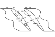
図3は、飛行体100の右翼側着脱部140の一例を概略的に示す。図3では、他の飛行体との接続について説明すべく、飛行体200の左翼側着脱部230を合わせて図示している。飛行体200の左翼側着脱部230は、飛行体100の左翼側着脱部130と同様の構成を有する。
FIG. 3 schematically shows an example of the right wing side attachment / detachment section 140 of the aircraft 100. In FIG. 3, the left wing side attachment / detachment portion 230 of the aircraft 200 is also shown in order to explain the connection with another aircraft. The left wing side attachment / detachment section 230 of the aircraft 200 has the same configuration as the left wing side attachment / detachment section 130 of the aircraft 100.
右翼側着脱部140は、構造凹接続部142、測位センサ144、信号接続部146、及び電力接続部148を有する。左翼側着脱部230は、構造凸接続部232、信号接続部236及び電力接続部238を有する。
The right wing side attachment / detachment section 140 has a structural concave connection section 142, a positioning sensor 144, a signal connection section 146, and a power connection section 148. The left wing side attachment / detachment portion 230 has a structural convex connection portion 232, a signal connection portion 236, and a power connection portion 238.
構造凹接続部142は、構造凸接続部232と嵌合する構造を有する。図3では、2つの構造凹接続部142を例示しているが、構造凹接続部142の数はこれに限らない。また、凹凸の関係は、右翼側着脱部140と左翼側着脱部230とで逆であってもよい。
The structural concave connecting portion 142 has a structure that fits with the structural convex connecting portion 232. In FIG. 3, two structural concave connection portions 142 are illustrated, but the number of structural concave connection portions 142 is not limited to this. Further, the relationship of the unevenness may be reversed between the right wing side attaching / detaching part 140 and the left wing side attaching / detaching part 230.
測位センサ144は、測位センサ144と対向する物体の位置を測定する。測位センサ144の方式は、レーザ式、超音波式、及び赤外線式等、任意の方式であってよい。測位センサ144は、右翼側着脱部140と左翼側着脱部130との両方に配置されてもよい。
The positioning sensor 144 measures the position of an object facing the positioning sensor 144. The positioning sensor 144 may be of any type such as a laser type, an ultrasonic type, and an infrared type. The positioning sensor 144 may be arranged in both the right wing side attaching / detaching part 140 and the left wing side attaching / detaching part 130.
信号接続部146は、構造凹接続部142と構造凸接続部232とが嵌合した場合に、信号接続部236と接続する。飛行体100は、信号接続部146を介して、飛行体200との間で信号の送受信を行うことができる。
The signal connecting portion 146 connects with the signal connecting portion 236 when the structural concave connecting portion 142 and the structural convex connecting portion 232 are fitted together. The aircraft 100 can send and receive signals to and from the aircraft 200 via the signal connection unit 146.
電力接続部148は、構造凹接続部142と構造凸接続部232とが嵌合した場合に、電力接続部238と接続する。飛行体100は、電力接続部148を介して、飛行体200との間で電力伝送を行うことができる。
The power connecting portion 148 connects with the power connecting portion 238 when the structure concave connecting portion 142 and the structure convex connecting portion 232 are fitted together. The air vehicle 100 can perform power transmission with the air vehicle 200 via the power connection unit 148.
なお、飛行体100は、電力接続部148に代えて、燃料管を備えてもよい。当該燃料管は、構造凹接続部142と構造凸接続部232とが嵌合した場合に、左翼側着脱部230に配置された燃料管と接続されてよい。飛行体100は、燃料管を介して、飛行体200との間で燃料の需給を行うことができる。
Note that the aircraft 100 may include a fuel pipe instead of the power connection unit 148. The fuel pipe may be connected to the fuel pipe arranged in the left wing side attaching / detaching portion 230 when the structural concave connection portion 142 and the structural convex connection portion 232 are fitted. The aircraft 100 can supply and demand fuel to and from the aircraft 200 via the fuel pipe.
図4は、飛行体200と合体している飛行体100の一例を概略的に示す。ここでは、飛行体100の右翼側着脱部140と、飛行体200の左翼側着脱部230とが接続されることによって、飛行体100と飛行体200とが合体している場合を例示している。
FIG. 4 schematically shows an example of the air vehicle 100 combined with the air vehicle 200. Here, an example is shown in which the right wing side attachment / detachment section 140 of the aircraft 100 and the left wing side attachment / detachment section 230 of the aircraft 200 are connected to combine the aircraft 100 and the aircraft 200. .
飛行体100は、飛行体200と合体することによって、飛行体200との間で電力伝送を行える。飛行体100は、例えば、飛行体200から電力を受給する。また、飛行体100は、例えば、飛行体200に対して電力を供給する。
The air vehicle 100 can perform electric power transmission with the air vehicle 200 by being united with the air vehicle 200. The aircraft 100 receives electric power from the aircraft 200, for example. Further, the flying object 100 supplies power to the flying object 200, for example.
また、飛行体100及び飛行体200が燃料タンクを有する場合、飛行体100は、飛行体200と合体することによって、飛行体200との間で燃料を需給できる。飛行体100は、例えば、飛行体200から燃料を受給する。また、飛行体100は、例えば、飛行体200に対して燃料を供給する。
When the aircraft 100 and the aircraft 200 have a fuel tank, the aircraft 100 can supply and demand fuel to and from the aircraft 200 by being combined with the aircraft 200. The aircraft 100 receives fuel from the aircraft 200, for example. Further, the aircraft 100 supplies fuel to the aircraft 200, for example.
また、飛行体100は、飛行体200と合体することによって、飛行体200による推力を受けたり、飛行体200に対して推力を与えたりすることができる。
Further, the air vehicle 100 can receive thrust by the air vehicle 200 or can give thrust to the air vehicle 200 by being united with the air vehicle 200.
また、飛行体100は、飛行体200と合体することによって、飛行体200と協働して通信エリアを形成することができる。これにより、飛行体100のみで通信エリアを形成する場合と比較して、通信キャパシティを高めたり、通信エリアを広げたり、指向性を高めたりすることができる。
Further, the air vehicle 100 can form a communication area in cooperation with the air vehicle 200 by being united with the air vehicle 200. As a result, the communication capacity can be increased, the communication area can be expanded, and the directivity can be increased, as compared with the case where the communication area is formed only by the flying object 100.
制御装置400は、例えば、飛行体100が形成する通信エリア150の通信状況が予め定められた条件を満たす場合に、飛行体200と合体するための制御信号を飛行体100に送信する。具体例として、制御装置400は、飛行体100が形成する通信エリア150における通信トラフィックが予め定められた閾値より高い場合に、飛行体200と合体するための制御信号を飛行体100に送信する。飛行体100と飛行体200とを合体させることにより、通信キャパシティを増加させることができ、通信トラフィックの増加に適切に対応させることができる。制御装置400は、飛行体100の合体対象として、飛行体100と同様の構成を有する飛行体200を選択してよい。また、制御装置400は、飛行体100の合体対象として、飛行体100による無線通信サービスよりも通信キャパシティが大きい無線通信サービスを提供可能な飛行体200を選択してもよい。これにより、通信キャパシティをより効率的に増加させることができる。
The control device 400 transmits a control signal for combining with the flying object 200 to the flying object 100, for example, when the communication condition of the communication area 150 formed by the flying object 100 satisfies a predetermined condition. As a specific example, when the communication traffic in the communication area 150 formed by the air vehicle 100 is higher than a predetermined threshold, the control device 400 transmits a control signal for combining with the air vehicle 200 to the air vehicle 100. By combining the flying body 100 and the flying body 200, it is possible to increase the communication capacity and appropriately cope with an increase in communication traffic. The control device 400 may select the flying body 200 having the same configuration as that of the flying body 100, as a uniting target of the flying body 100. Further, the control device 400 may select, as a target to be combined with the aircraft 100, the aircraft 200 capable of providing a wireless communication service having a larger communication capacity than the wireless communication service provided by the aircraft 100. As a result, the communication capacity can be increased more efficiently.
制御装置400は、例えば、飛行体100の緯度が予め定められた条件を満たす場合に、飛行体200と合体するための制御信号を飛行体100に送信する。具体例として、制御装置400は、飛行体100の緯度が予め定められた緯度よりも高い場合に、飛行体200と合体するための制御信号を飛行体100に送信する。飛行体100と飛行体200とを合体させることにより、飛行体200から飛行体100への電力供給を行わせることができ、飛行体100が、太陽電池パネル118による発電量が低下する緯度の高い地域に移動した場合に、飛行体100に対して適切に電力を補充することができる。制御装置400は、飛行体100の合体対象として、電力供給部を有する飛行体200を選択してよい。また、制御装置400は、飛行体100の合体対象として、電力供給部を有し、バッテリ残量が予め定められた閾値よりも多い飛行体200を選択してよい。
The control device 400, for example, transmits a control signal for merging with the flying body 200 to the flying body 100 when the latitude of the flying body 100 satisfies a predetermined condition. As a specific example, control device 400 transmits to aircraft 100 a control signal for joining aircraft 200 when the latitude of aircraft 100 is higher than a predetermined latitude. By combining the flying body 100 and the flying body 200, electric power can be supplied from the flying body 200 to the flying body 100, and the flying body 100 has a high latitude where the amount of power generated by the solar cell panel 118 decreases. When moving to an area, the aircraft 100 can be appropriately replenished with electric power. The control device 400 may select the aircraft 200 having the power supply unit as a target to be combined with the aircraft 100. Further, the control device 400 may select an aircraft 200 that has a power supply unit and has a battery remaining amount that is greater than a predetermined threshold value, as a target for combining the aircraft 100.
制御装置400は、例えば、飛行体100の飛行エリアの気象状況が予め定められた条件を満たす場合に、飛行体200と合体するための制御信号を飛行体100に送信する。具体例として、制御装置400は、飛行体100の飛行エリアの気流速度が予め定められた閾値よりも速い場合に、飛行体200と合体するための制御信号を飛行体100に送信する。飛行体100と飛行体200とを合体させることにより、飛行体200の推力を飛行体100に与えることができ、気流に逆らって飛行するサポートをすることができる。制御装置400は、飛行体100の合体対象として、飛行体100と同様の構成を有する飛行体200を選択してよい。また、制御装置400は、飛行体100が備える推進機構よりも強い推力を発生する推進機構を有する飛行体200を選択してもよい。これにより、飛行体100に対してより強い推力を与えることができる。
The control device 400, for example, transmits a control signal for merging with the air vehicle 200 to the air vehicle 100 when the weather condition of the flight area of the air vehicle 100 satisfies a predetermined condition. As a specific example, the control device 400 transmits, to the air vehicle 100, a control signal for combining with the air vehicle 200 when the airflow velocity in the flight area of the air vehicle 100 is higher than a predetermined threshold value. By combining the flying body 100 and the flying body 200, the thrust of the flying body 200 can be applied to the flying body 100, and it is possible to support the flight against the air current. The control device 400 may select the flying body 200 having the same configuration as that of the flying body 100, as a uniting target of the flying body 100. In addition, the control device 400 may select the aircraft 200 having a propulsion mechanism that generates a stronger thrust than the propulsion mechanism included in the aircraft 100. Thereby, a stronger thrust can be applied to the flying object 100.
飛行体100及び飛行体200が合体した後、飛行体100が備える複数のプロペラ108と、飛行体200が備える複数のプロペラ208のうちの少なくともいずれかが停止されてよい。例えば、飛行体100が左翼側のプロペラ108を停止させ、飛行体200が右翼側のプロペラ208を停止させる。また、例えば、飛行体100が右翼側のプロペラ108を停止させ、飛行体200が左翼側のプロペラ208を停止させる。これにより、推力のバランスを保ちつつ、飛行体100及び飛行体200の消費電力を適切に低減することができる。このようなプロペラの停止は、飛行体100及び飛行体200が主体的に実行してよく、また、制御装置400による制御に従って飛行体100及び飛行体200が実行してもよい。
After the aircraft 100 and the aircraft 200 are combined, at least one of the plurality of propellers 108 included in the aircraft 100 and the plurality of propellers 208 included in the aircraft 200 may be stopped. For example, the air vehicle 100 stops the left wing side propeller 108, and the air vehicle 200 stops the right wing side propeller 208. Further, for example, the flying body 100 stops the right-wing-side propeller 108, and the flying body 200 stops the left-wing-side propeller 208. As a result, the power consumption of the flying object 100 and the flying object 200 can be appropriately reduced while maintaining the thrust balance. The stop of the propeller may be executed by the flying body 100 and the flying body 200 independently, or may be executed by the flying body 100 and the flying body 200 under the control of the control device 400.
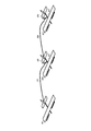
図5は、飛行体200及び飛行体300と合体している飛行体100の一例を概略的に示す。図5では、飛行体100の両側に飛行体200と飛行体300とが合体している場合を例示しているが、これに限らず、飛行体100と飛行体200とが合体し、飛行体200と飛行体300とが合体することによって、飛行体100、飛行体200及び飛行体300が合体してもよい。
FIG. 5 schematically shows an example of an air vehicle 100 combined with the air vehicle 200 and the air vehicle 300. Although FIG. 5 exemplifies a case where the flying body 200 and the flying body 300 are combined on both sides of the flying body 100, the invention is not limited to this, and the flying body 100 and the flying body 200 are combined, By combining 200 and the flying body 300, the flying body 100, the flying body 200, and the flying body 300 may be combined.
飛行体200は、飛行体100と同様の構成を有する飛行体であってよい。また、飛行体200は、電力補充用の飛行体であってもよい。また、飛行体200は、推力強化用の飛行体であってもよい。また、飛行体200は、通信機能強化用の飛行体であってもよい。
The air vehicle 200 may be an air vehicle having the same configuration as the air vehicle 100. The aircraft 200 may also be a vehicle for supplementing power. Further, the flying body 200 may be a flying body for thrust enhancement. Further, the flying body 200 may be a flying body for enhancing communication function.
飛行体300は、飛行体100と同様の構成を有する飛行体であってよい。また、飛行体300は、電力補充用の飛行体であってもよい。また、飛行体300は、推力強化用の飛行体であってもよい。また、飛行体300は、通信機能強化用の飛行体であってもよい。
The air vehicle 300 may be an air vehicle having the same configuration as the air vehicle 100. Further, the flying body 300 may be a flying body for supplementing power. Further, the flying object 300 may be a flying object for thrust enhancement. Further, the flying object 300 may be a flying object for enhancing the communication function.
例えば、飛行体100に対して、飛行体100と同様の構成を有する飛行体200及び飛行体300を合体させることにより、飛行体200のみを合体させる場合と比較して、飛行体100に対して提供可能な電力供給量、燃料供給量、通信キャパシティ、及び推力を増加することができる。
For example, by combining the flying body 100 with the flying body 200 and the flying body 300 having the same configuration as the flying body 100, the flying body 100 can be compared with the case where only the flying body 200 is joined. The available power supply, fuel supply, communication capacity, and thrust can be increased.
また、例えば、飛行体100に対して、電力補充用の飛行体200と、推力強化用の飛行体300とを合体させることによって、飛行体100に対する電力補充と推力強化とを効率的に行うことができる。
Further, for example, by combining the flying body 200 for power replenishment and the flying body 300 for thrust enhancement with respect to the flying body 100, power replenishment and thrust enhancement for the flying body 100 can be efficiently performed. You can
また、例えば、飛行体100と、飛行体100と同様の構成を有する飛行体200との間に、推力強化用の飛行体300を合体させることにより、飛行体100及び飛行体200の両方に対して効率的に推力を加えることができる。
In addition, for example, by combining the aircraft 100 for thrust enhancement between the aircraft 100 and the aircraft 200 having the same configuration as the aircraft 100, both the aircraft 100 and the aircraft 200 can be provided. And thrust can be applied efficiently.
飛行体100、飛行体200及び飛行体300が合体した後、飛行体100が備える複数のプロペラ108と、飛行体200が備える複数のプロペラ208と、飛行体300が備える複数のプロペラ308のうちの少なくともいずれかが停止されてよい。例えば、飛行体100の複数のプロペラ108が停止されてよい。また、例えば、飛行体200の右翼側のプロペラ208と、飛行体300の左翼側のプロペラ308とが停止されてよい。また、例えば、飛行体200の複数のプロペラ208と、飛行体300の複数のプロペラ308とが停止されてよい。
After the air vehicle 100, the air vehicle 200, and the air vehicle 300 are combined, a plurality of propellers 108 included in the air vehicle 100, a plurality of propellers 208 included in the air vehicle 200, and a plurality of propellers 308 included in the air vehicle 300 are included. At least one may be stopped. For example, the plurality of propellers 108 of the air vehicle 100 may be shut down. Further, for example, the propeller 208 on the right wing side of the aircraft 200 and the propeller 308 on the left wing side of the aircraft 300 may be stopped. Further, for example, the plurality of propellers 208 of the aircraft 200 and the plurality of propellers 308 of the aircraft 300 may be stopped.
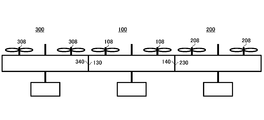
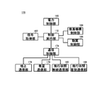
図6は、飛行体100、飛行体200及び飛行体300によって形成される通信エリア600の一例を概略的に示す。ここでは、飛行体100が中央アンテナ110、左翼側アンテナ112及び右翼側アンテナ114を備え、飛行体200が中央アンテナ210、左翼側アンテナ212及び右翼側アンテナ214を備え、飛行体300が中央アンテナ310、左翼側アンテナ312及び右翼側アンテナ314を備える場合を例示している。
FIG. 6 schematically shows an example of a communication area 600 formed by the air vehicle 100, the air vehicle 200, and the air vehicle 300. Here, the air vehicle 100 includes a central antenna 110, a left-wing antenna 112, and a right-wing antenna 114, the air vehicle 200 includes a central antenna 210, a left-wing antenna 212, and a right-wing antenna 214, and the air vehicle 300 includes a central antenna 310. , The left-wing side antenna 312 and the right-wing side antenna 314 are illustrated.
飛行体100は、中央アンテナ110、左翼側アンテナ112、右翼側アンテナ114、中央アンテナ210、左翼側アンテナ212、右翼側アンテナ214、中央アンテナ310、左翼側アンテナ312、及び右翼側アンテナ314によるビームフォーミングによって通信エリア600を形成してよい。これにより、飛行体100のみによって通信エリアを形成する場合と比較して、アンテナ数を増加することができ、通信キャパシティを増加したり、指向性を高めたりすることができる。
The air vehicle 100 includes beam forming with a central antenna 110, a left-wing antenna 112, a right-wing antenna 114, a central antenna 210, a left-wing antenna 212, a right-wing antenna 214, a central antenna 310, a left-wing antenna 312, and a right-wing antenna 314. May form a communication area 600. As a result, the number of antennas can be increased, the communication capacity can be increased, and the directivity can be increased, as compared with the case where the communication area is formed by only the flying object 100.
上記実施形態では、複数の飛行体が水平方向に合体する例を挙げて説明したが、これに限らない。複数の飛行体は、上下方向に合体してもよい。また、複数の飛行体は、斜め方向に合体してもよい。複数の飛行体のそれぞれは、水平方向のみ合体可能であってよく、上下方向のみ合体可能であってよく、斜め方向のみ合体可能であってよい。また、複数の飛行体のそれぞれは、水平方向、上下方向、及び斜め方向のうち、複数の方向に合体可能であってもよい。すなわち、複数の飛行体のそれぞれは、状況に応じて、他の飛行体と水平方向に合体したり、上下方向に合体したり、斜め方向に合体したりしてよい。
In the above-described embodiment, an example in which a plurality of flying objects are united in the horizontal direction has been described, but the present invention is not limited to this. The plurality of air vehicles may be combined in the vertical direction. Further, the plurality of air vehicles may be united in an oblique direction. Each of the plurality of air vehicles may be united only in the horizontal direction, may be united only in the vertical direction, and may be united only in the diagonal direction. In addition, each of the plurality of air vehicles may be able to be combined in a plurality of directions among a horizontal direction, a vertical direction, and an oblique direction. That is, each of the plurality of air vehicles may be horizontally combined with other air vehicles, vertically combined, or obliquely combined with each other, depending on the situation.
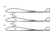
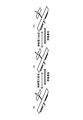
図7は、上下方向に合体している飛行体100、飛行体200及び飛行体300の一例を概略的に示す。図7に示す例において、飛行体100は、飛行体100の上面側に配置された上面側着脱部160を備える。飛行体200は、飛行体200の上面側に配置された上面側着脱部260と、飛行体200の下面側に配置された接続部264とを備える。接続部264は、飛行体200の下面側に収納可能であってよい。接続部264の先端には、下面側着脱部262が配置されている。飛行体300は、飛行体300の下面側に配置された接続部364を備える。接続部364は、飛行体300の下面側に収納可能であってよい。接続部364の先端には、下面側着脱部362が配置されている。
FIG. 7 schematically shows an example of the flying body 100, the flying body 200, and the flying body 300 that are vertically combined. In the example shown in FIG. 7, the aircraft 100 includes an upper surface side attachment / detachment section 160 arranged on the upper surface side of the aircraft 100. The aircraft 200 includes an upper surface side attachment / detachment portion 260 arranged on the upper surface side of the aircraft 200 and a connecting portion 264 arranged on the lower surface side of the aircraft 200. The connection portion 264 may be retractable on the lower surface side of the aircraft 200. The lower surface side attachment / detachment portion 262 is arranged at the tip of the connection portion 264. The aircraft 300 includes a connecting portion 364 arranged on the lower surface side of the aircraft 300. The connecting portion 364 may be housed on the lower surface side of the aircraft 300. The lower surface side attachment / detachment portion 362 is arranged at the tip of the connection portion 364.
飛行体100と飛行体200とが合体する場合、飛行体100及び飛行体200の少なくともいずれかが、上面側着脱部160と下面側着脱部262との位置関係を調整して、上面側着脱部160と下面側着脱部262とを接続させてよい。上面側着脱部160は、右翼側着脱部140と同様に、構造凹接続部、測位センサ、信号接続部、及び電力接続部を有してよい。下面側着脱部262は、左翼側着脱部230と同様に、構造凸接続部、信号接続部、及び電力接続部を有してよい。飛行体100と飛行体200とは、上面側着脱部160及び下面側着脱部262を介して、通信を実行可能であってよく、また、電力伝送を実行可能であってよい。また、飛行体100と飛行体200とは、上面側着脱部160及び下面側着脱部262を介して、燃料需給を実行可能であってもよい。図3に示したように主翼104の先端に着脱部を配置する場合と比較して、上面又は下面に着脱部を配置することによって、着脱部の接触面積を広くすることができ、より素早い燃料補充を行うことができる。飛行体200と飛行体300とが合体する場合については、飛行体100と飛行体200とが合体する場合と同様であってよい。
When the flying body 100 and the flying body 200 are united, at least one of the flying body 100 and the flying body 200 adjusts the positional relationship between the upper surface side attaching / detaching portion 160 and the lower surface side attaching / detaching portion 262 to form the upper surface side attaching / detaching portion. 160 and the lower surface side attaching / detaching portion 262 may be connected. The upper surface side attachment / detachment section 160 may have a structural concave connection section, a positioning sensor, a signal connection section, and a power connection section, like the right wing side attachment / detachment section 140. The lower surface side attachment / detachment portion 262 may have a structural convex connection portion, a signal connection portion, and a power connection portion similarly to the left wing side attachment / detachment portion 230. The air vehicle 100 and the air vehicle 200 may be able to perform communication and power transmission via the upper surface side attachment / detachment section 160 and the lower surface side attachment / detachment section 262. Further, the aircraft 100 and the aircraft 200 may be able to execute fuel supply and demand via the upper surface side attachment / detachment section 160 and the lower surface side attachment / detachment section 262. As compared with the case where the attachment / detachment portion is arranged at the tip of the main wing 104 as shown in FIG. 3, the contact area of the attachment / detachment portion can be increased by arranging the attachment / detachment portion on the upper surface or the lower surface, and thus the fuel can be discharged more quickly. Can be replenished. The case where the flying body 200 and the flying body 300 are combined may be the same as the case where the flying body 100 and the flying body 200 are combined.
飛行体100は、飛行体100の下面側に配置された不図示の接続部を備えてもよい。当該接続部の先端には、下面側着脱部が配置される。また、飛行体300は、飛行体300の上面側に配置された不図示の上面側着脱部を備えてもよい。
The air vehicle 100 may include a connection unit (not shown) arranged on the lower surface side of the air vehicle 100. The lower surface side attachment / detachment portion is arranged at the tip of the connection portion. Further, the flying object 300 may include an upper surface side attaching / detaching portion (not shown) arranged on the upper surface side of the flying object 300.
なお、図7では、飛行体200が飛行体200の下面側に接続部264を備えるように、飛行体の下面側に接続部が配置される例を挙げて説明したが、これに限らない。接続部は、飛行体の上面側に配置されてもよい。また、接続部が、飛行体の上面側及び下面側の両方に配置されてもよい。この場合、上方の飛行体の下面側の接続部と、下方の飛行体の上面側の接続部とが着脱することによって、上方の飛行体と下方の飛行体とが合体分離する。
Note that, in FIG. 7, an example in which the connecting portion is arranged on the lower surface side of the flying object 200 so that the flying object 200 includes the connecting portion 264 on the lower surface side of the flying object 200 has been described, but the present invention is not limited to this. The connection portion may be arranged on the upper surface side of the aircraft. In addition, the connecting portions may be arranged on both the upper surface side and the lower surface side of the aircraft. In this case, the upper flight body and the lower flight body are united and separated by attaching and detaching the lower flight side connection section of the upper flight body and the upper flight side connection section of the lower flight body.
飛行体100、飛行体200及び飛行体300が上下方向に合体する場合において、飛行体100、飛行体200及び飛行体300は、通信相手を分担してもよい。図7に示す例において、例えば、飛行体100が地上と通信し、飛行体200が他の飛行体と無線通信し、飛行体300が通信衛星と通信してよい。これにより、飛行体100、飛行体200及び飛行体300は、互いに邪魔されることなく、通信相手と通信することができる。なお、この場合、飛行体100は、他の飛行体と無線通信する機能と、通信衛星と通信する機能とを有さなくてもよい。また、飛行体200は、地上と通信する機能と、通信衛星と通信する機能とを有さなくてもよい。また、飛行体300は、地上と通信する機能と、他の飛行体と無線通信する機能とを有さなくてもよい。これにより、飛行体100、飛行体200及び飛行体300のそれぞれの構成を簡略化でき、小型化することができる。
When the air vehicle 100, the air vehicle 200, and the air vehicle 300 are combined in the vertical direction, the air vehicle 100, the air vehicle 200, and the air vehicle 300 may share communication partners. In the example shown in FIG. 7, for example, the flying body 100 may communicate with the ground, the flying body 200 may wirelessly communicate with another flying body, and the flying body 300 may communicate with a communication satellite. Accordingly, the flying object 100, the flying object 200, and the flying object 300 can communicate with the communication partner without being interfered with each other. In this case, the flying body 100 may not have the function of wirelessly communicating with another flying body and the function of communicating with a communication satellite. Further, the air vehicle 200 may not have a function of communicating with the ground and a function of communicating with a communication satellite. In addition, the air vehicle 300 may not have a function of communicating with the ground and a function of wirelessly communicating with another air vehicle. Thereby, each structure of the flying body 100, the flying body 200, and the flying body 300 can be simplified and miniaturized.
図8は、斜め方向に合体している飛行体100、飛行体200及び飛行体300の一例を概略的に示す。ここでは、図7と異なる点を主に説明する。
FIG. 8 schematically shows an example of a flying body 100, a flying body 200, and a flying body 300 that are united in an oblique direction. Here, differences from FIG. 7 will be mainly described.
接続部264は、飛行体200の下面側から飛行体200の前方に向けて突き出している。接続部364は、飛行体300の下面側から飛行体300の前方に向けて突き出している。すなわち、飛行体の下面側に接続部が配置される場合、当該接続部は、当該飛行体の下面側から当該飛行体の前方に向けて突き出していてよい。また、例えば、飛行体の上面側に接続部が配置される場合、当該接続部は、当該飛行体の上面側から当該飛行体の後方に向けて突き出していてよい。このような構造を有することによって、下方の飛行体を前方寄りに配置し、上方の飛行体を後方よりに配置することができ、図7のように上下方向に合体する場合と比較して、空気抵抗を低減することができる。なお、飛行体に対する接続部の角度は、変更可能であってよい。
The connecting portion 264 projects from the lower surface side of the aircraft 200 toward the front of the aircraft 200. The connecting portion 364 projects from the lower surface side of the flying body 300 toward the front of the flying body 300. That is, when the connection portion is arranged on the lower surface side of the aircraft, the connection portion may project from the lower surface side of the aircraft toward the front of the aircraft. In addition, for example, when the connection portion is arranged on the upper surface side of the flight vehicle, the connection portion may project from the upper surface side of the flight vehicle toward the rear of the flight vehicle. By having such a structure, it is possible to arrange the lower flying body closer to the front side and the upper flying body from the rear side, as compared with the case where the upper flying body is combined vertically as shown in FIG. Air resistance can be reduced. The angle of the connecting portion with respect to the flying body may be changeable.
図9は、斜め方向に合体している飛行体100、飛行体200及び飛行体300の一例を概略的に示す。図9は、飛行体100、飛行体200及び飛行体300を上方から見た場合を例示している。
FIG. 9 schematically shows an example of a flying body 100, a flying body 200, and a flying body 300 that are united in an oblique direction. FIG. 9 illustrates the case where the flying body 100, the flying body 200, and the flying body 300 are viewed from above.
飛行体100、飛行体200及び飛行体300が斜め方向に合体することによって、中央アンテナ110、左翼側アンテナ112、右翼側アンテナ114、中央アンテナ210、左翼側アンテナ212、右翼側アンテナ214、中央アンテナ310、左翼側アンテナ312、及び右翼側アンテナ314を2次元に配置することができる。飛行体100は、2次元に配置された中央アンテナ110、左翼側アンテナ112、右翼側アンテナ114、中央アンテナ210、左翼側アンテナ212、右翼側アンテナ214、中央アンテナ310、左翼側アンテナ312、及び右翼側アンテナ314を用いて、2次元のビームフォーミングを実行してよい。これにより、通信エリアの形成の自由度を高めたり、指向性を高めたりすることができる。
By combining the flying body 100, the flying body 200, and the flying body 300 in an oblique direction, the central antenna 110, the left-wing antenna 112, the right-wing antenna 114, the central antenna 210, the left-wing antenna 212, the right-wing antenna 214, and the central antenna. 310, the left wing side antenna 312, and the right wing side antenna 314 can be arranged two-dimensionally. The aircraft 100 includes a two-dimensionally arranged central antenna 110, left-wing antenna 112, right-wing antenna 114, central antenna 210, left-wing antenna 212, right-wing antenna 214, central antenna 310, left-wing antenna 312, and right-wing. Two-dimensional beamforming may be performed using the side antenna 314. As a result, the degree of freedom in forming the communication area can be increased and the directivity can be increased.
図10は、ケーブルによって合体している飛行体100、飛行体200及び飛行体300の一例を概略的に示す。図10に示すように、飛行体100、飛行体200及び飛行体300は、ケーブルを介して合体可能であってもよい。
FIG. 10 schematically shows an example of a flying body 100, a flying body 200, and a flying body 300 that are combined by a cable. As shown in FIG. 10, the flying vehicle 100, the flying vehicle 200, and the flying vehicle 300 may be able to be combined via a cable.
図10に示す例において、飛行体100は、他の飛行体と物理的に着脱する着脱部168を有するケーブル166を備える。飛行体200は、他の飛行体と物理的に着脱する着脱部268を有するケーブル266と、飛行体200の上面側に配置された上面側着脱部260とを備える。飛行体300は、飛行体300の上面側に配置された上面側着脱部360を備える。なお、飛行体100は、飛行体200における上面側着脱部260と同様の上面側着脱部を備えてもよい。また、飛行体300は、飛行体100におけるケーブル166と同様のケーブルを備えてもよい。
In the example shown in FIG. 10, the flight vehicle 100 includes a cable 166 having an attachment / detachment section 168 that is physically attached / detached to / from another flight vehicle. The aircraft 200 includes a cable 266 having an attachment / detachment portion 268 that is physically attached / detached to / from another aircraft, and an upper surface side attachment / detachment portion 260 arranged on the upper surface side of the aircraft 200. The flying object 300 includes an upper surface side attaching / detaching part 360 arranged on the upper surface side of the flying object 300. The aircraft 100 may include an upper surface side attachment / detachment portion similar to the upper surface side attachment / detachment portion 260 of the aircraft 200. The air vehicle 300 may also include a cable similar to the cable 166 in the air vehicle 100.
飛行体100と飛行体200とが合体する場合、例えば、飛行体200が主体となって、飛行体200が上面側着脱部260と着脱部168との位置関係を調整して、上面側着脱部260と着脱部168とを接続させてよい。また、例えば、飛行体100がケーブル166をリール式で収納可能であり、収納状態で飛行体100が飛行体200に近づいて、着脱部168を上面側着脱部260に接続させた後、飛行体100が飛行体200から離間するようにして、着脱部168と上面側着脱部260とを接続させてもよい。
When the flying body 100 and the flying body 200 are united, for example, the flying body 200 is the main body, and the flying body 200 adjusts the positional relationship between the upper surface side attachment / detachment section 260 and the attachment / detachment section 168 to form the upper surface side attachment / detachment section. The 260 and the attaching / detaching part 168 may be connected. In addition, for example, the aircraft 100 can store the cable 166 in a reel type, and after the aircraft 100 approaches the aircraft 200 in the stored state and the attaching / detaching portion 168 is connected to the upper surface side attaching / detaching portion 260, The attachment / detachment portion 168 and the upper surface-side attachment / detachment portion 260 may be connected such that 100 is separated from the flying object 200.
着脱部168は、右翼側着脱部140と同様に、構造凹接続部、測位センサ、信号接続部、及び電力接続部を有してよい。上面側着脱部260は、左翼側着脱部230と同様に、構造凸接続部、信号接続部、及び電力接続部を有してよい。飛行体100は、ケーブル166を介して、飛行体200と通信するケーブル通信部を有してよい。また、飛行体100は、ケーブル166を介して飛行体200との間で電力を伝送する電力伝送部を有してよい。また、飛行体100は、ケーブル166を介して飛行体200との間で燃料を需給する燃料需給部を有してよい。
Like the right wing side attaching / detaching portion 140, the attaching / detaching portion 168 may have a structural concave connection portion, a positioning sensor, a signal connection portion, and a power connection portion. The upper surface side attachment / detachment portion 260 may have a structure convex connection portion, a signal connection portion, and a power connection portion similarly to the left wing side attachment / detachment portion 230. Aircraft 100 may have a cable communicator that communicates with aircraft 200 via cable 166. In addition, the aircraft 100 may include a power transmission unit that transmits power to and from the aircraft 200 via the cable 166. The aircraft 100 may also have a fuel supply / demand unit that supplies and receives fuel to / from the aircraft 200 via the cable 166.
飛行体200と飛行体300とが合体する場合については、飛行体100と飛行体200とが合体する場合と同様であってよい。
The case where the flying body 200 and the flying body 300 are combined may be the same as the case where the flying body 100 and the flying body 200 are combined.
図11は、仮想的に合体している飛行体100、飛行体200及び飛行体300の一例を概略的に示す。ここで、飛行体が仮想的に合体しているとは、飛行体が物理的に合体しているのではなく、無線通信及び無線電力伝送が可能である状態のことをいう。
FIG. 11 schematically shows an example of a flying vehicle 100, a flying vehicle 200, and a flying vehicle 300 that are virtually combined. Here, that the flying body is virtually united does not mean that the flying body is physically united, but a state in which wireless communication and wireless power transmission are possible.
図11に示す例において、飛行体100、飛行体200及び飛行体300はそれぞれ、他の飛行体と無線通信する無線通信部と、他の飛行体との間で無線電力伝送を実行する電力伝送実行部とを有する。
In the example illustrated in FIG. 11, the air vehicle 100, the air vehicle 200, and the air vehicle 300 each have a wireless communication unit that wirelessly communicates with another aircraft, and power transmission that performs wireless power transmission with the other aircraft. And an execution unit.
無線通信部は、いわゆるV2Vに用いられる通信方式によって無線通信してよい。例えば、無線通信部は、ビームフォーミングによって無線通信する。電力伝送実行部は、電磁誘導方式等の任意の方式によって無線電力伝送を実行してよい。
The wireless communication unit may perform wireless communication by a communication method used for so-called V2V. For example, the wireless communication unit performs wireless communication by beamforming. The power transmission execution unit may execute wireless power transmission by an arbitrary method such as an electromagnetic induction method.
複数の飛行体を仮想的に合体させることにより、着脱部などの物理的な合体部分を不要としつつ、複数の飛行体を合体させた場合と実質的に同等の機能を実現することができる。
By virtually combining a plurality of flight vehicles, it is possible to realize a function that is substantially the same as when a plurality of flight vehicles are combined, while eliminating the need for a physical combination part such as a detachable part.
飛行体100は、無線通信部及び電力伝送実行部によって、無線通信部と無線通信を実行可能であり、かつ、電力伝送実行部との間で無線電力伝送を実行可能なインターフェースを有する、飛行体100と同一又は異なる種類の他の飛行体と仮想的に合体する。すなわち、飛行体100は、共通のインターフェースを有していれば、異なる種類の飛行体とも仮想的に合体可能である。
The air vehicle 100 has an interface capable of executing wireless communication with the wireless communication unit by the wireless communication unit and the power transmission execution unit, and having an interface capable of executing wireless power transmission with the power transmission execution unit. Virtually merge with another flight vehicle of the same or different type as 100. That is, the flight vehicle 100 can virtually combine with flight vehicles of different types as long as they have a common interface.
飛行体100は、例えば、無線通信部及び電力伝送実行部を有する飛行体200及び飛行体300等と仮想的に合体する。また、飛行体100は、例えば、飛行体100が有する無線通信部と無線通信を実行可能であり、かつ、飛行体100が有する電力伝送実行部との間で無線電力伝送を実行可能なインターフェースを有する、気球型の飛行体、飛行船型の飛行体、及び回転翼型の飛行体等と仮想的に合体する。このようなインターフェースが共通化、オープン化していけば、飛行体の機体のタイプに依存せず、メーカーにも依存せずに、複数の飛行体を、1機として仮想的に合体させて、運用することが可能になる。また、このような仮想的な合体により、多様なフォーメーション毎に運用方法を変えることもできる。機体・通信サービス等の運用装置で統合運用が可能である。
The flying body 100 is virtually combined with the flying body 200, the flying body 300, and the like having a wireless communication unit and a power transmission execution unit, for example. In addition, the aircraft 100 has, for example, an interface that can perform wireless communication with a wireless communication unit included in the aircraft 100 and can perform wireless power transmission with the power transmission execution unit included in the aircraft 100. It is virtually combined with a balloon-type flying body, an airship-type flying body, a rotary-wing-type flying body, and the like. If such an interface becomes common and open, it will be possible to operate by virtually combining multiple aircraft as one aircraft without depending on the aircraft type of the aircraft and the manufacturer. It becomes possible to do. Further, by such virtual combination, it is possible to change the operation method for each of various formations. Integrated operation is possible with operation devices such as aircraft and communication services.
図12は、制御装置400の機能構成一例を概略的に示す。制御装置400は、受信部402、格納部403、バッテリ残量取得部404、発電量取得部406、受光量取得部408、位置情報取得部410、選択部414、及び飛行体制御部416を備える。なお、制御装置400がこれらのすべての構成を備えることは必須とは限らない。
FIG. 12 schematically shows an example of the functional configuration of the control device 400. The control device 400 includes a reception unit 402, a storage unit 403, a battery remaining amount acquisition unit 404, a power generation amount acquisition unit 406, a received light amount acquisition unit 408, a position information acquisition unit 410, a selection unit 414, and an aircraft control unit 416. . It is not essential that the control device 400 has all of these configurations.
受信部402は、複数の飛行体のそれぞれの状況に関連する情報を受信する。受信部402は、複数の飛行体のそれぞれから、それぞれの飛行体の状況に関連する情報を受信してよい。また、受信部402は、複数の飛行体のいずれかが、他の飛行体から収集した情報を、当該飛行体から受信してもよい。また、受信部402は、管理システム500から、複数の飛行体のそれぞれの状況に関連する情報を受信してもよい。
The receiving unit 402 receives information related to each situation of a plurality of air vehicles. The receiving unit 402 may receive, from each of the plurality of air vehicles, information related to the situation of each air vehicle. In addition, the reception unit 402 may receive, from any of the plurality of air vehicles, information collected from other air vehicles from the air vehicle. In addition, the receiving unit 402 may receive information related to each situation of the plurality of air vehicles from the management system 500.
当該情報は、飛行体の構成情報を含んでよい。当該情報は、飛行体の機能情報を含んでよい。当該情報は、飛行体の位置情報を含んでよい。当該情報は、飛行体のバッテリのバッテリ残量を含んでよい。当該情報は、飛行体の太陽電池パネルによる発電量を含んでよい。当該情報は、飛行体の太陽電池パネルが受光する受光量を含んでよい。格納部403は、受信部402が受信した情報を格納する。
The information may include the configuration information of the air vehicle. The information may include functional information of the air vehicle. The information may include position information of the air vehicle. The information may include the remaining battery charge of the aircraft battery. The information may include the amount of power generated by the solar panel of the aircraft. The information may include the amount of light received by the solar cell panel of the aircraft. The storage unit 403 stores the information received by the reception unit 402.
バッテリ残量取得部404は、複数の飛行体のそれぞれのバッテリのバッテリ残量を取得する。バッテリ残量取得部404は、格納部403から、複数の飛行体のそれぞれのバッテリ残量を取得してよい。
The battery remaining amount acquisition unit 404 acquires the battery remaining amount of each battery of a plurality of flying objects. The battery remaining amount acquisition unit 404 may acquire the battery remaining amount of each of the plurality of flying objects from the storage unit 403.
発電量取得部406は、複数の飛行体のそれぞれの発電量を取得する。発電量取得部406は、格納部403から、複数の飛行体のそれぞれの発電量を取得してよい。
The power generation amount acquisition unit 406 acquires the power generation amount of each of the plurality of air vehicles. The power generation amount acquisition unit 406 may acquire the power generation amount of each of the plurality of flying objects from the storage unit 403.
受光量取得部408は、複数の飛行体のそれぞれの受光量を取得する。受光量取得部408は、格納部403から、複数の飛行体のそれぞれの受光量を取得してよい。
The light reception amount acquisition unit 408 acquires the light reception amount of each of a plurality of flying objects. The received light amount acquisition unit 408 may acquire the received light amount of each of the plurality of flying objects from the storage unit 403.
位置情報取得部410は、複数の飛行体のそれぞれの位置情報を取得する。位置情報取得部410は、格納部403から複数の飛行体のそれぞれの位置情報を取得してよい。
The position information acquisition unit 410 acquires position information of each of a plurality of air vehicles. The position information acquisition unit 410 may acquire the position information of each of the plurality of air vehicles from the storage unit 403.
選択部414は、複数の飛行体から、他の飛行体と合体する必要がある飛行体を選択する。選択部414は、例えば、複数の飛行体のうち、予め定められた条件を満たす飛行体を選択する。また、選択部414は、複数の飛行体から、選択した飛行体と合体させる合体対象の飛行体を選択する。選択部414は、例えば、複数の飛行体のうち、合体の必要がある飛行体により近い飛行体を選択する。選択部414は、満たした条件に応じて、合体対象の飛行体を選択してもよい。
The selecting unit 414 selects a flight object that needs to be combined with another flight object from a plurality of flight objects. The selection unit 414 selects, for example, an air vehicle that satisfies a predetermined condition from among a plurality of air vehicles. Further, the selection unit 414 selects, from the plurality of flight vehicles, a flight vehicle to be merged with the selected flight vehicle. The selecting unit 414 selects, for example, of a plurality of flying bodies, a flying body closer to a flying body that needs to be combined. The selection unit 414 may select the aircraft to be combined according to the satisfied conditions.
選択部414は、例えば、通信エリア150がカバーしている地上エリアの状況が予め定められた条件を満たす飛行体を、合体の必要がある飛行体として選択する。例えば、選択部414は、スーパールーラルエリアを飛行していた飛行体が、ルーラルエリアに移動する場合に、当該飛行体を合体の必要がある飛行体として選択する。また、選択部414は、例えば、ルーラルエリアを飛行していた飛行体が、アーバンエリアに移動する場合に、当該飛行体を合体の必要がある飛行体として選択する。この場合、選択部414は、例えば、合体の必要がある飛行体と同様の構成を有する飛行体を合体対象の飛行体として選択する。また、選択部414は、例えば、合体の必要がある飛行体による無線通信サービスよりも通信キャパシティが大きい無線通信サービスを提供可能な飛行体を合体対象の飛行体として選択する。
The selecting unit 414 selects, for example, an aircraft that needs to be united with an aircraft whose condition in the ground area covered by the communication area 150 satisfies a predetermined condition. For example, the selecting unit 414 selects a flying vehicle that has been flying in the super-rural area as a flying vehicle that needs to be united when moving to the rural area. Further, the selecting unit 414 selects, for example, a flying body that has been flying in the rural area as a flying body that needs to be united when moving to the urban area. In this case, the selection unit 414 selects, for example, an aircraft having a configuration similar to that of an aircraft that needs to be merged, as an aircraft to be merged. Further, the selection unit 414 selects, for example, a flying body that can provide a wireless communication service having a larger communication capacity than the wireless communication service of the flying body that needs to be combined, as a flying object to be combined.
また、選択部414は、例えば、形成する通信エリア150の通信状況が予め定められた条件を満たす飛行体を、合体の必要がある飛行体として選択する。当該条件は、例えば、通信エリア150における通信トラフィックが予め定められた閾値より高いことである。この場合、選択部414は、例えば、合体の必要がある飛行体と同様の構成を有する飛行体を合体対象の飛行体として選択する。また、選択部414は、例えば、合体の必要がある飛行体による無線通信サービスよりも通信キャパシティが大きい無線通信サービスを提供可能な飛行体を合体対象の飛行体として選択する。選択部414は、合体の必要がある飛行体と、合体対象の飛行体とを合体させた後、合体した飛行体によって形成される通信エリアの通信状況が予め定められた条件を満たす場合に、合体した飛行体に対して合体させる合体対象の飛行体をさらに選択してもよい。
Further, the selecting unit 414 selects, for example, a flying body that satisfies the predetermined communication condition of the communication area 150 to be formed, as a flying body that needs to be united. The condition is, for example, that the communication traffic in the communication area 150 is higher than a predetermined threshold value. In this case, the selection unit 414 selects, for example, an aircraft having a configuration similar to that of an aircraft that needs to be merged, as an aircraft to be merged. Further, the selection unit 414 selects, for example, a flying body that can provide a wireless communication service having a larger communication capacity than the wireless communication service of the flying body that needs to be combined, as a flying object to be combined. The selecting unit 414, after combining the flight object that needs to be combined with the flight object to be combined, when the communication status of the communication area formed by the combined flight object satisfies a predetermined condition, You may further select the aircraft to be merged with the merged aircraft.
選択部414は、通信エリア150における通信トラフィックが、予め定められた第1の閾値と、第1の閾値よりも高い第2の閾値との間である場合と、第2の閾値より高い場合とで、合体対象の飛行体を異ならせてもよい。例えば、選択部414は、通信エリア150における通信トラフィックが第1の閾値と第2の閾値との間である場合、合体する必要がある飛行体と同様の構成を有する飛行体を選択し、第2の閾値より高い場合、合体する必要がある飛行体による無線通信サービスよりも通信キャパシティが大きい無線通信サービスを提供可能な飛行体を選択する。
The selecting unit 414 determines whether the communication traffic in the communication area 150 is between a predetermined first threshold value and a second threshold value higher than the first threshold value, and when the communication traffic is higher than the second threshold value. Then, the flying object to be combined may be different. For example, when the communication traffic in the communication area 150 is between the first threshold value and the second threshold value, the selection unit 414 selects an aircraft having a configuration similar to that of an aircraft that needs to be combined, When it is higher than the threshold value of 2, the aircraft which can provide the wireless communication service having the larger communication capacity than the wireless communication service by the aircraft which needs to be combined is selected.
また、選択部414は、例えば、バッテリ残量が予め定められた閾値より少ない飛行体を、合体の必要がある飛行体として選択する。この場合、選択部414は、合体した他の飛行体に電力を供給する電力供給部を有する飛行体を合体対象の飛行体として選択する。選択部414は、電力供給部を有し、かつ、バッテリのバッテリ残量が予め定められた閾値より多い飛行体を合体対象の飛行体として選択してもよい。
Further, the selection unit 414 selects, for example, an aircraft having a battery remaining amount less than a predetermined threshold as an aircraft that needs to be combined. In this case, the selection unit 414 selects a flight vehicle that has a power supply unit that supplies power to another flight vehicle that has been combined as a flight object to be combined. The selecting unit 414 may include a power supply unit and may select, as a flying object to be combined, an flying object in which the battery remaining amount of the battery is larger than a predetermined threshold value.
また、選択部414は、例えば、太陽電池パネルの発電量が予め定められた閾値より少ない飛行体を、合体の必要がある飛行体として選択する。この場合、選択部414は、合体した他の飛行体に電力を供給する電力供給部を有する飛行体を合体対象の飛行体として選択する。選択部414は、電力供給部を有し、かつ、バッテリのバッテリ残量が予め定められた閾値より多い飛行体を合体対象の飛行体として選択してもよい。
Further, the selection unit 414 selects, for example, an aircraft whose power generation amount of the solar cell panel is less than a predetermined threshold as an aircraft that needs to be combined. In this case, the selection unit 414 selects a flight vehicle that has a power supply unit that supplies power to another flight vehicle that has been combined as a flight object to be combined. The selecting unit 414 may include a power supply unit and may select, as a flying object to be combined, an flying object in which the battery remaining amount of the battery is larger than a predetermined threshold value.
また、選択部414は、例えば、太陽電池パネルの受光量が予め定められた閾値より少ない飛行体を、合体の必要がある飛行体として選択する。この場合、選択部414は、合体した他の飛行体に電力を供給する電力供給部を有する飛行体を合体対象の飛行体として選択する。選択部414は、電力供給部を有し、かつ、バッテリのバッテリ残量が予め定められた閾値より多い飛行体を合体対象の飛行体として選択してもよい。
Further, the selection unit 414 selects, for example, an aircraft whose amount of light received by the solar cell panel is smaller than a predetermined threshold as an aircraft that needs to be combined. In this case, the selection unit 414 selects a flight vehicle that has a power supply unit that supplies power to another flight vehicle that has been combined as a flight object to be combined. The selecting unit 414 may include a power supply unit and may select, as a flying object to be combined, an flying object in which the battery remaining amount of the battery is larger than a predetermined threshold value.
また、選択部414は、飛行する飛行エリアの気象状況が予め定められた条件を満たす飛行体を、合体の必要がある飛行体として選択する。当該条件は、例えば、飛行エリアの気流速度が予め定められた閾値より速いことである。また、選択部414は、これから離陸しようとする飛行体を、合体の必要がある飛行体として選択する。これらの場合、選択部414は、例えば、合体の必要がある飛行体と同様の構成を有する飛行体を合体対象の飛行体として選択する。また、例えば、選択部414は、合体の必要がある飛行体が搭載する推進機構よりも強い推力を発生する推進機構を有する飛行体を選択する。
Further, the selecting unit 414 selects, as a flying body that needs to be united, a flying body in which the weather condition of the flying area satisfies a predetermined condition. The condition is, for example, that the air velocity in the flight area is faster than a predetermined threshold value. In addition, the selection unit 414 selects a flight vehicle that is about to take off as a flight vehicle that needs to be united. In these cases, the selection unit 414 selects, for example, an air vehicle having the same configuration as the air vehicle that needs to be united, as the air vehicle to be united. In addition, for example, the selection unit 414 selects an aircraft having a propulsion mechanism that generates a stronger thrust than the propulsion mechanism mounted on the aircraft that needs to be united.
飛行体制御部416は、選択部414によって選択された合体の必要がある飛行体と、合体対象の飛行体との合体を制御する。飛行体制御部416は、合体の必要がある飛行体及び合体対象の飛行体のいずれかに、合体相手の情報と、合体指示とを含む制御信号を送信してよい。飛行体制御部416は、合体の必要がある飛行体及び合体対象の飛行体のそれぞれに、合体相手の情報と、合体指示とを含む制御信号を送信してもよい。合体相手の情報は、合体相手の飛行体を識別する識別情報を含んでよい。また、合体相手の情報は、合体相手の飛行体の位置情報を含んでよい。
The flight body control unit 416 controls the combination of the flight vehicle selected by the selection unit 414 that needs to be merged with the flight vehicle to be merged. The flying body control unit 416 may transmit a control signal including information of a joining partner and a joining instruction to any of the flying body that needs to be joined and the flying body to be joined. The flying body control unit 416 may transmit a control signal including information of a joining partner and a joining instruction to each of the flying body that needs to be joined and the flying body to be joined. The information of the coalescing partner may include identification information for identifying the flying body of the coalescing partner. Further, the information of the coalescing partner may include the position information of the flying body of the coalescing partner.
図13は、制御装置400による処理の流れの一例を概略的に示す。ここでは、制御装置400が複数の飛行体の状況を監視している状態を開始状態として説明する。
FIG. 13 schematically shows an example of the flow of processing by the control device 400. Here, a state in which the control device 400 monitors the states of a plurality of air vehicles will be described as a start state.
ステップ(ステップをSと省略して記載する場合がある。)102では、選択部414が、複数の飛行体のうち、合体の必要があるか否かを判定するための予め定められた条件を満たす飛行体が存在するか否かを判定する。存在すると判定された場合、S104に進む。
In step (the step may be abbreviated as S) 102, the selection unit 414 sets a predetermined condition for determining whether or not the plurality of air vehicles need to be combined. It is determined whether there is an air vehicle to satisfy. If it is determined that the file exists, the process proceeds to S104.
S104では、選択部414が、満たされた条件に応じて、合体の必要がある飛行体と合体させる合体対象の飛行体を選択する。S106では、飛行体制御部416が、合体の必要がある飛行体と合体対象の飛行体とを合体させるための制御信号を、合体の必要がある飛行体及び合体対象の飛行体に送信する。これにより、合体の必要がある飛行体と合体対象の飛行体と合体させることができる。
In S104, the selection unit 414 selects a flight object to be combined with a flight object that needs to be combined according to the satisfied conditions. In step S106, the flight control unit 416 transmits a control signal for combining the flight vehicle that needs to be merged with the flight vehicle that is the target to be merged to the flight vehicle that needs to be merged and the flight vehicle that is the target to be merged. As a result, it is possible to combine a flight object that needs to be merged with a flight object that is the target of the merger.
S108では、監視を終了する終了指示を受領したか否かを判定する。受領していないと判定した場合、S102に戻り、受領したと判定した場合、処理を終了する。
In S108, it is determined whether or not an end instruction to end the monitoring has been received. If it is determined that it has not been received, the process returns to S102, and if it is determined that it has been received, the processing ends.
図14は、飛行体100が備える制御装置170の機能構成の一例を概略的に示す。制御装置170は、例えば、飛行体100の本体102に配置される。制御装置170は、制御実行部172、通信制御部174、地上通信部176、衛星通信部178、飛行体間無線通信部180、信号取得部182、推進機構制御部184、動翼制御部186、飛行体間着脱通信部188、及び電力制御部190を備える。なお、制御装置170がこれらのすべての構成を備えることは必須とは限らない。
FIG. 14 schematically shows an example of the functional configuration of the control device 170 included in the air vehicle 100. The control device 170 is arranged in the main body 102 of the aircraft 100, for example. The control device 170 includes a control execution unit 172, a communication control unit 174, a ground communication unit 176, a satellite communication unit 178, an inter-aircraft wireless communication unit 180, a signal acquisition unit 182, a propulsion mechanism control unit 184, a moving blade control unit 186, An inter-aircraft attachment / detachment communication unit 188 and a power control unit 190 are provided. Note that it is not essential that the control device 170 has all of these configurations.
制御実行部172は、各種制御を実行する。通信制御部174は、各種通信を制御する。制御実行部172は、地上通信部176、衛星通信部178、飛行体間無線通信部180、及び飛行体間着脱通信部188による通信を制御する。
The control execution unit 172 executes various controls. The communication control unit 174 controls various types of communication. The control execution unit 172 controls communication by the ground communication unit 176, the satellite communication unit 178, the inter-flight body wireless communication unit 180, and the inter-flight body attachment / detachment communication unit 188.
地上通信部176は、地上に通信エリア150を形成して、地上の通信装置と通信する。地上通信部176は、例えば、ユーザ端末30と通信する。また、地上通信部176は、例えば、制御装置400と通信する。また、地上通信部176は、例えば、管理システム500と通信する。
The ground communication unit 176 forms a communication area 150 on the ground and communicates with a communication device on the ground. The ground communication unit 176 communicates with the user terminal 30, for example. The ground communication unit 176 also communicates with the control device 400, for example. The ground communication unit 176 also communicates with the management system 500, for example.
衛星通信部178は、通信衛星と通信する。衛星通信部178は、通信衛星との通信用のアンテナを用いて、通信衛星と通信する。
The satellite communication unit 178 communicates with a communication satellite. The satellite communication unit 178 communicates with the communication satellite using an antenna for communication with the communication satellite.
飛行体間無線通信部180は、他の飛行体と無線通信する。飛行体間無線通信部180は、他の飛行体と無線通信するためのアンテナを用いて、他の飛行体と無線通信する。飛行体間無線通信部180は、例えば、当該アンテナを用いて他の飛行体との間でC2リンクを形成し、C2リンクを介して通信する。また、飛行体間無線通信部180は、例えば、当該アンテナを用いて他の飛行体に対してビームフォーミングを行うことにより、他の飛行体と無線通信する。
The inter-aircraft wireless communication unit 180 wirelessly communicates with other aircraft. The inter-flight body wireless communication unit 180 wirelessly communicates with another flight object using an antenna for wireless communication with another flight object. The inter-aircraft wireless communication unit 180 forms a C2 link with another aircraft using the antenna, and communicates via the C2 link, for example. In addition, the inter-aircraft wireless communication unit 180 wirelessly communicates with another aircraft by performing beamforming on another aircraft using the antenna, for example.
信号取得部182は、制御装置400によって送信された制御信号を取得する。信号取得部182は、例えば、地上通信部176を介して、制御装置400から制御信号を受信する。信号取得部182は、衛星通信部178を介して、制御装置400によって通信衛星50を介して送信された制御信号を受信してもよい。信号取得部182は、他の飛行体が制御装置400から受信した制御信号を、飛行体間無線通信部180を介して当該他の飛行体から取得してもよい。
The signal acquisition unit 182 acquires the control signal transmitted by the control device 400. The signal acquisition unit 182 receives a control signal from the control device 400 via the ground communication unit 176, for example. The signal acquisition unit 182 may receive, via the satellite communication unit 178, the control signal transmitted by the control device 400 via the communication satellite 50. The signal acquisition unit 182 may acquire the control signal received by the other flying body from the control device 400 from the other flying body via the inter-aircraft wireless communication unit 180.
推進機構制御部184は、推進機構を制御する。推進機構制御部184は、例えば、複数のプロペラ108を制御する。
The propulsion mechanism control unit 184 controls the propulsion mechanism. The propulsion mechanism control unit 184 controls, for example, the plurality of propellers 108.
動翼制御部186は、動翼を制御する。動翼制御部186は、動翼122を制御してよい。動翼制御部186は、動翼124を制御してよい。動翼制御部186は、動翼126を制御してよい。
The moving blade control unit 186 controls the moving blades. The blade control unit 186 may control the blade 122. The blade control unit 186 may control the blade 124. The blade control unit 186 may control the blade 126.
制御実行部172は、推進機構制御部184及び動翼制御部186に、推進機構及び動翼を制御させることによって、飛行体100の飛行を制御してよい。制御実行部172は、例えば、信号取得部182が制御信号を取得した場合に、当該制御信号に基づいて、推進機構制御部184及び動翼制御部186に推進機構及び動翼を制御させることによって、合体対象の飛行体との合体を行う。
The control execution unit 172 may control the flight of the air vehicle 100 by causing the propulsion mechanism control unit 184 and the moving blade control unit 186 to control the propulsion mechanism and the moving blades. For example, when the signal acquisition unit 182 acquires the control signal, the control execution unit 172 causes the propulsion mechanism control unit 184 and the moving blade control unit 186 to control the propulsion mechanism and the moving blade based on the control signal. , Merge with the target flight vehicle.
飛行体間着脱通信部188は、合体した飛行体との間で通信を行う。飛行体間着脱通信部188は、着脱部を介して、合体した飛行体との間で通信を行う。
The inter-aircraft attachment / detachment communication unit 188 communicates with a united air vehicle. The inter-flight body attachment / detachment communication unit 188 communicates with the united flight body via the attachment / detachment unit.
電力制御部190は、合体した飛行体との間で電力伝送を行う。電力制御部190は、バッテリ120の電力を、着脱部を介して、合体した飛行体に供給するよう制御してよい。また、電力制御部190は、着脱部を介して、合体した飛行体から受給した電力をバッテリ120に蓄電させる。
The electric power control unit 190 transmits electric power to the combined flying body. The power control unit 190 may control the power of the battery 120 to be supplied to the combined flying body via the attachment / detachment unit. Further, the power control unit 190 causes the battery 120 to store the power received from the combined flying body via the attaching / detaching unit.
飛行体100は、電力制御部190に代えて、合体した飛行体との間で燃料需給を行う燃料需給部を備えてもよい。また、飛行体100は、電力制御部190とともに、燃料需給部を備えてもよい。燃料需給部は、飛行体100が備える燃料タンク内の燃料を、着脱部を介して、合体した飛行体に供給するよう制御してよい。また、燃料需給部は、着脱部を介して、合体した飛行体から受給した燃料を、飛行体100が備える燃料タンク内に蓄積するように制御してよい。
The aircraft 100 may be provided with a fuel supply / demand unit that performs fuel supply / demand with the combined aircraft, instead of the power control unit 190. In addition, the air vehicle 100 may include a fuel supply / demand unit as well as the power control unit 190. The fuel supply / demand unit may control the fuel in the fuel tank of the aircraft 100 to be supplied to the combined aircraft via the attachment / detachment unit. In addition, the fuel supply / demand unit may control the fuel received from the combined flying body via the attachment / detachment unit so as to be accumulated in the fuel tank included in the flying body 100.
図15は、制御実行部172による処理の流れを概略的に示す。ここでは、信号取得部182が制御装置400から制御信号を受信した場合の処理の流れを説明する。
FIG. 15 schematically shows the flow of processing by the control execution unit 172. Here, the flow of processing when the signal acquisition unit 182 receives a control signal from the control device 400 will be described.
S202では、制御実行部172が、制御信号に含まれる合体対象の飛行体の識別情報によって識別した合体対象の飛行体のGPS信号を受信しているか否かを判定する。制御実行部172は、例えば、制御装置400から、合体対象の飛行体のGPS信号を受信している場合や、合体対象の飛行体から飛行体間無線通信部180を介して合体対象の飛行体のGPS信号を受信している場合に、受信していると判定する。受信していると判定した場合、S204に進む。
In S202, the control execution unit 172 determines whether or not the GPS signal of the flight object to be combined identified by the identification information of the flight object to be combined included in the control signal is received. The control execution unit 172 receives, for example, the GPS signal of the flight object to be combined from the control device 400, or the flight object to be combined from the flight object to be combined via the inter-aircraft wireless communication unit 180. If the GPS signal is received, it is determined that the GPS signal is received. If it is determined that it is received, the process proceeds to S204.
S204では、制御実行部172が、推進機構制御部184及び動翼制御部186を介して推進機構及び動翼を制御し、合体対象の飛行体の隣に移動する。S206では、制御実行部172が、測位センサ144で合体対象の飛行体を検出できるか否かを判定する。検出できた場合、S208に進み、検出できない場合、S204に戻る。
In S204, the control execution unit 172 controls the propulsion mechanism and the moving blades via the propulsion mechanism control unit 184 and the moving blade control unit 186, and moves to the side of the aircraft to be combined. In S206, the control execution unit 172 determines whether or not the positioning sensor 144 can detect the flying object to be combined. If it can be detected, the process proceeds to S208, and if it cannot be detected, the process returns to S204.
S208では、制御実行部172が、推進機構制御部184及び動翼制御部186を介して推進機構及び動翼を制御し、飛行体100の着脱部と、合体対象の飛行体の着脱部とを接続する。S210では、制御実行部172が、飛行体間着脱通信部188を介して、合体対象の飛行体に信号を送信する。S212では、制御実行部172が、合体対象の飛行体からAck信号が返ってくるか否かを判定する。Ack信号が返ってきた場合、S214に進み、返ってこない場合、S208に戻る。
In step S208, the control execution unit 172 controls the propulsion mechanism and the moving blades via the propulsion mechanism control unit 184 and the moving blade control unit 186, and connects the attachment / detachment portion of the aircraft 100 and the attachment / detachment portion of the aircraft to be combined. Connecting. In S210, the control execution unit 172 transmits a signal to the air vehicle to be combined via the inter-aircraft attachment / detachment communication unit 188. In S212, the control execution unit 172 determines whether or not an Ack signal is returned from the flying object to be combined. When the Ack signal is returned, the process proceeds to S214, and when it is not returned, the process returns to S208.
S214では、制御実行部172が、合体対象の飛行体との通信接続を完了する。S216では、制御実行部172が、合体対象の飛行体との電気接続を完了する。例えば、電力接続部148と、電力制御部190との間にリレーが配置されていてよく、制御実行部172は、当該リレーを短絡することによって、電力接続を完了してよい。そして、処理を終了する。
In S214, the control execution unit 172 completes the communication connection with the flight object to be combined. In S216, the control execution unit 172 completes the electrical connection with the flying object to be combined. For example, a relay may be arranged between the power connection unit 148 and the power control unit 190, and the control execution unit 172 may complete the power connection by short-circuiting the relay. Then, the process ends.
図16は、制御装置400又は制御装置170として機能するコンピュータ1000の一例を概略的に示す。本実施形態に係るコンピュータ1000は、ホストコントローラ1092により相互に接続されるCPU1010、RAM1030、及びグラフィックコントローラ1085を有するCPU周辺部と、入出力コントローラ1094によりホストコントローラ1092に接続されるROM1020、通信I/F1040、記憶装置1050及び入出力チップ1080を有する入出力部を備える。
FIG. 16 schematically shows an example of the computer 1000 that functions as the control device 400 or the control device 170. The computer 1000 according to the present embodiment includes a CPU peripheral unit having a CPU 1010, a RAM 1030, and a graphic controller 1085 that are mutually connected by a host controller 1092, a ROM 1020 that is connected to the host controller 1092 by an input / output controller 1094, and a communication I / O. An input / output unit including an F1040, a storage device 1050, and an input / output chip 1080 is provided.
CPU1010は、ROM1020及びRAM1030に格納されたプログラムに基づいて動作し、各部の制御を行う。グラフィックコントローラ1085は、CPU1010などがRAM1030内に設けたフレーム・バッファ上に生成する画像データを取得し、ディスプレイ上に表示させる。これに代えて、グラフィックコントローラ1085は、CPU1010などが生成する画像データを格納するフレーム・バッファを、内部に含んでもよい。
The CPU 1010 operates based on programs stored in the ROM 1020 and the RAM 1030, and controls each part. The graphic controller 1085 acquires image data generated by the CPU 1010 or the like on a frame buffer provided in the RAM 1030 and displays it on the display. Alternatively, the graphic controller 1085 may internally include a frame buffer that stores image data generated by the CPU 1010 or the like.
通信I/F1040は、有線又は無線によりネットワークを介して他の装置と通信する。また、通信I/F1040は、通信を行うハードウェアとして機能する。記憶装置1050は、ハードディスクドライブ及びソリッドステートドライブ等であってよく、CPU1010が使用するプログラム及びデータを格納する。
The communication I / F 1040 communicates with other devices via a network by wire or wirelessly. Further, the communication I / F 1040 functions as hardware that performs communication. The storage device 1050 may be a hard disk drive, a solid state drive, or the like, and stores programs and data used by the CPU 1010.
ROM1020は、コンピュータ1000が起動時に実行するブート・プログラム及びコンピュータ1000のハードウェアに依存するプログラムなどを格納する。入出力チップ1080は、例えばUSBポート、パラレルポート、シリアルポート、キーボードポート、マウスポートなどを介して各種の入出力装置を入出力コントローラ1094へと接続する。
The ROM 1020 stores a boot program executed by the computer 1000 at startup and a program dependent on the hardware of the computer 1000. The input / output chip 1080 connects various input / output devices to the input / output controller 1094 via, for example, a USB port, a parallel port, a serial port, a keyboard port, a mouse port, and the like.
RAM1030を介して記憶装置1050に提供されるプログラムは、ICカードなどの記録媒体に格納されて利用者によって提供される。プログラムは、記録媒体から読み出され、RAM1030を介して記憶装置1050にインストールされ、CPU1010において実行される。
The program provided to the storage device 1050 via the RAM 1030 is stored in a recording medium such as an IC card and provided by the user. The program is read from the recording medium, installed in the storage device 1050 via the RAM 1030, and executed by the CPU 1010.
コンピュータ1000にインストールされ、コンピュータ1000を制御装置400又は制御装置170として機能させるプログラムは、CPU1010などに働きかけて、コンピュータ1000を、制御装置400又は制御装置170の各部としてそれぞれ機能させてよい。これらのプログラムに記述された情報処理は、コンピュータ1000に読込まれることにより、ソフトウエアと上述した各種のハードウェア資源とが協働した具体的手段である受信部402、格納部403、バッテリ残量取得部404、発電量取得部406、受光量取得部408、位置情報取得部410、選択部414、及び飛行体制御部416として機能する。また、これらのプログラムに記述された情報処理は、コンピュータ1000に読込まれることにより、ソフトウエアと上述した各種のハードウェア資源とが協働した具体的手段である制御実行部172、通信制御部174、地上通信部176、衛星通信部178、飛行体間無線通信部180、信号取得部182、推進機構制御部184、動翼制御部186、飛行体間着脱通信部188、及び電力制御部190として機能する。そして、これらの具体的手段によって、本実施形態におけるコンピュータ1000の使用目的に応じた情報の演算又は加工を実現することにより、使用目的に応じた特有の制御装置400又は制御装置170が構築される。
A program installed in the computer 1000 and causing the computer 1000 to function as the control device 400 or the control device 170 may act on the CPU 1010 or the like to cause the computer 1000 to function as each unit of the control device 400 or the control device 170, respectively. The information processing described in these programs is read by the computer 1000, and is a specific means in which software and the various hardware resources described above cooperate with each other, namely, the receiving unit 402, the storage unit 403, and the battery remaining. It functions as the amount acquisition unit 404, the power generation amount acquisition unit 406, the received light amount acquisition unit 408, the position information acquisition unit 410, the selection unit 414, and the flying body control unit 416. Further, the information processing described in these programs is read by the computer 1000, so that the control execution unit 172 and the communication control unit, which are concrete means in which software and the various hardware resources described above cooperate with each other. 174, ground communication unit 176, satellite communication unit 178, inter-flight body wireless communication unit 180, signal acquisition unit 182, propulsion mechanism control unit 184, moving blade control unit 186, inter-flight body attachment / detachment communication unit 188, and power control unit 190. Function as. Then, by implementing the calculation or processing of information according to the purpose of use of the computer 1000 in this embodiment by these specific means, a specific control device 400 or control device 170 according to the purpose of use is constructed. .
以上、本発明を実施の形態を用いて説明したが、本発明の技術的範囲は上記実施の形態に記載の範囲には限定されない。上記実施の形態に、多様な変更または改良を加えることが可能であることが当業者に明らかである。その様な変更または改良を加えた形態も本発明の技術的範囲に含まれ得ることが、請求の範囲の記載から明らかである。
Although the present invention has been described using the embodiments, the technical scope of the present invention is not limited to the scope described in the above embodiments. It is apparent to those skilled in the art that various modifications and improvements can be added to the above-described embodiment. It is apparent from the scope of the claims that the embodiments added with such changes or improvements can be included in the technical scope of the present invention.
請求の範囲、明細書、および図面中において示した装置、システム、プログラム、および方法における動作、手順、ステップ、および段階などの各処理の実行順序は、特段「より前に」、「先立って」などと明示しておらず、また、前の処理の出力を後の処理で用いるのでない限り、任意の順序で実現しうることに留意すべきである。請求の範囲、明細書、および図面中の動作フローに関して、便宜上「まず、」、「次に、」などを用いて説明したとしても、この順で実施することが必須であることを意味するものではない。
The order of execution of each process such as operations, procedures, steps, and stages in the devices, systems, programs, and methods shown in the claims, the specification, and the drawings is "before" or "prior to". It should be noted that the output of the previous process can be realized in any order unless the output of the previous process is used in the subsequent process. The operation flow in the claims, the description, and the drawings is described using “first,” “next,” and the like for the sake of convenience, but it means that it is essential to carry out in this order. is not.
10 システム、20 ネットワーク、30 ユーザ端末、40 ゲートウェイ、50 通信衛星、100 飛行体、102 本体、104 主翼、106 水平尾翼、107 垂直尾翼、108 プロペラ、110 中央アンテナ、112 左翼側アンテナ、114 右翼側アンテナ、116 GPS送受信機、118 太陽電池パネル、120 バッテリ、122 動翼、124 動翼、126 動翼、130 左翼側着脱部、140 右翼側着脱部、142 構造凹接続部、144 測位センサ、146 信号接続部、148 電力接続部、150 通信エリア、152 サブセル、160 上面側着脱部、166 ケーブル、168 着脱部、170 制御装置、172 制御実行部、174 通信制御部、176 地上通信部、178 衛星通信部、180 飛行体間無線通信部、182 信号取得部、184 推進機構制御部、186 動翼制御部、188 飛行体間着脱通信部、190 電力制御部、200 飛行体、210 中央アンテナ、212 左翼側アンテナ、214 右翼側アンテナ、230 左翼側着脱部、232 構造凸接続部、236 信号接続部、238 電力接続部、260 上面側着脱部、262 下面側着脱部、264 接続部、266 ケーブル、268 着脱部、300 飛行体、310 中央アンテナ、312 左翼側アンテナ、314 右翼側アンテナ、362 下面側着脱部、364 接続部、400 制御装置、402 受信部、403 格納部、404 バッテリ残量取得部、406 発電量取得部、408 受光量取得部、410 位置情報取得部、414 選択部、416 飛行体制御部、500 管理システム、600 通信エリア、1000 コンピュータ、1010 CPU、1020 ROM、1030 RAM、1040 通信I/F、1050 記憶装置、1080 入出力チップ、1085 グラフィックコントローラ、1092 ホストコントローラ、1094 入出力コントローラ
10 systems, 20 networks, 30 user terminals, 40 gateways, 50 communication satellites, 100 flight vehicles, 102 bodies, 104 main wings, 106 horizontal stabilizers, 107 vertical stabilizers, 108 propellers, 110 central antennas, 112 left wing side antennas, 114 right wing sides Antenna, 116 GPS transceiver, 118 solar battery panel, 120 battery, 122 rotor blade, 124 rotor blade, 126 rotor blade, 130 left wing side attachment / detachment section, 140 right wing side attachment / detachment section, 142 structure concave connection section, 144 positioning sensor, 146 Signal connection part, 148 power connection part, 150 communication area, 152 subcell, 160 upper surface side attachment / detachment part, 166 cable, 168 attachment / detachment part, 170 control device, 172 control execution part, 174 communication control part, 176 ground communication part, 1 8 satellite communication unit, 180 inter-aircraft wireless communication unit, 182 signal acquisition unit, 184 propulsion mechanism control unit, 186 rotor blade control unit, 188 inter-flight body detachable communication unit, 190 power control unit, 200 air vehicle, 210 central antenna , 212 left wing side antenna, 214 right wing side antenna, 230 left wing side attaching / detaching part, 232 structure convex connecting part, 236 signal connecting part, 238 power connecting part, 260 upper surface side attaching / detaching part, 262 lower surface side attaching / detaching part, 264 connecting part, 266 Cable, 268 attachment / detachment part, 300 flight object, 310 central antenna, 312 left wing side antenna, 314 right wing side antenna, 362 bottom surface attachment / detachment part, 364 connection part, 400 control device, 402 reception part, 403 storage part, 404 battery level Acquisition unit, 406 power generation amount acquisition unit, 408 received light amount acquisition unit 410 position information acquisition unit, 414 selection unit, 416 flight control unit, 500 management system, 600 communication area, 1000 computer, 1010 CPU, 1020 ROM, 1030 RAM, 1040 communication I / F, 1050 storage device, 1080 I / O chip , 1085 graphic controller, 1092 host controller, 1094 input / output controller
Claims (16)
- 飛行体であって、
地上に向けて照射するビームによって通信エリアを形成して前記通信エリア内のユーザ端末に無線通信サービスを提供するためのアンテナと、
他の飛行体と合体分離すべく前記他の飛行体と物理的に着脱する着脱部と
を備える飛行体。 A flying body,
An antenna for providing a wireless communication service to a user terminal in the communication area by forming a communication area by a beam irradiated toward the ground,
An aircraft comprising an attachment / detachment portion that is physically attached / detached to / from the other aircraft in order to unite and separate the other aircraft. - 前記飛行体及び前記他の飛行体が飛行中に、前記着脱部と前記他の飛行体が備える着脱部とを接続するように前記飛行体を制御する制御実行部
を備える、請求項1に記載の飛行体。 The control execution part which controls the said flying body so that the said attachment / detachment part and the attachment / detachment part with which this other flight body is equipped are provided with the control execution part while the said flight body and the said other flight body are flying. Flying body. - 前記着脱部を介して、前記他の飛行体と通信する着脱通信部
を備える、請求項1又は2に記載の飛行体。 The aircraft according to claim 1 or 2, further comprising: a detachable communication unit that communicates with the other aircraft via the detachable unit. - 前記着脱部を介して、前記他の飛行体との間で電力を伝送する電力伝送部
を備える、請求項1から3のいずれか一項に記載の飛行体。 The aircraft according to any one of claims 1 to 3, further comprising: a power transmission unit that transmits power to the other aircraft via the attachment / detachment unit. - 前記着脱部を介して、前記他の飛行体との間で燃料を需給する燃料需給部
を備える、請求項1から4のいずれか一項に記載の飛行体。 The aircraft according to any one of claims 1 to 4, further comprising a fuel supply / demand unit that supplies and receives fuel to / from the other aircraft via the attachment / detachment unit. - 前記着脱部は、
前記飛行体が有する主翼の右翼側に配置された右翼側着脱部と、
前記主翼の左翼側に配置された左翼側着脱部と
を含む、請求項1から5のいずれか一項に記載の飛行体。 The detachable part is
A right wing side attachment / detachment section arranged on the right wing side of the main wing of the flying body,
The left-wing side attachment / detachment portion arranged on the left-wing side of the main wing, The aircraft according to claim 1. - 前記着脱部は、前記飛行体の上面側に配置された上面側着脱部と、前記飛行体の下面側に配置された下面側着脱部との少なくともいずれかをさらに含む、請求項6に記載の飛行体。 7. The attachment / detachment section further includes at least one of an upper surface side attachment / detachment section arranged on an upper surface side of the flight vehicle and a lower surface side attachment / detachment section arranged on a lower surface side of the flight vehicle. Flying body.
- 前記着脱部は、前記飛行体の上面側に配置された上面側着脱部と、前記飛行体の下面側に配置された下面側着脱部との少なくともいずれかを含む、請求項1から5のいずれか一項に記載の飛行体。 6. The attachment / detachment section includes at least one of an upper surface side attachment / detachment section arranged on the upper surface side of the flight vehicle and a lower surface side attachment / detachment section arranged on the lower surface side of the flight vehicle. The aircraft according to item 1.
- 前記上面側着脱部は、前記飛行体の上面から前記飛行体の後方に向けて突き出す接続部に配置されており、
前記下面側着脱部は、前記飛行体の下面から前記飛行体の前方に向けて突き出す接続部に配置されている、請求項7又は8に記載の飛行体。 The upper surface side attachment / detachment portion is arranged in a connection portion protruding from the upper surface of the flying body toward the rear of the flying body,
The aircraft according to claim 7 or 8, wherein the lower surface side attachment / detachment portion is arranged at a connection portion protruding from a lower surface of the aircraft toward the front of the aircraft. - 前記アンテナは、前記飛行体の主翼の中央に配置された第1中央アンテナと、前記飛行体の主翼の左翼に配置された第1左翼側アンテナと、前記飛行体の主翼の右翼に配置された第1右翼側アンテナとを含み、
前記他の飛行体は、前記他の飛行体の主翼の中央に配置された第2中央アンテナと、前記他の飛行体の主翼の左翼に配置された第2左翼側アンテナと、前記他の飛行体の主翼の右翼に配置された第2右翼側アンテナとを含む、
請求項7から9のいずれか一項に記載の飛行体。 The antenna is a first central antenna arranged in the center of the main wing of the aircraft, a first left-wing antenna arranged on the left wing of the main wing of the aircraft, and a right wing of the main wing of the aircraft. Including a first right wing antenna,
The other flying body includes a second central antenna arranged in the center of the main wing of the other flying body, a second left wing side antenna arranged on the left wing of the main wing of the other flying body, and the other flight. A second right wing antenna disposed on the right wing of the main wing of the body,
The aircraft according to any one of claims 7 to 9. - 前記アンテナを用いて地上に前記通信エリアを形成する地上通信部
を備え、
前記地上通信部は、前記第1中央アンテナ、前記第1左翼側アンテナ、前記第1右翼側アンテナ、前記第2中央アンテナ、前記第2左翼側アンテナ、及び前記第2右翼側アンテナによるビームフォーミングによって、前記通信エリアを形成するよう制御する、請求項10に記載の飛行体。 A ground communication unit that forms the communication area on the ground using the antenna,
The terrestrial communication unit uses beamforming by the first central antenna, the first left wing antenna, the first right wing antenna, the second central antenna, the second left wing antenna, and the second right wing antenna. The aircraft according to claim 10, which is controlled to form the communication area. - 第1の飛行体、第2の飛行体、及び第3の飛行体を備えるシステムであって、
前記第1の飛行体は、
地上の通信装置と通信するためのアンテナと、
前記第1の飛行体の上面に配置され、前記第2の飛行体の下面に配置された下面着脱部と物理的に着脱する着脱部と、
前記着脱部を介して前記第2の飛行体と通信する着脱通信部と
を有し、
前記第2の飛行体は、前記第1の飛行体及び前記第3の飛行体以外の他の飛行体と通信するためのアンテナと、
前記第2の飛行体の下面に配置された前記下面着脱部と、
前記第2の飛行体の上面に配置され、前記第3の飛行体の下面に配置された下面着脱部と物理的に着脱する上面着脱部と、
前記下面着脱部を介して前記第2の飛行体と通信し、前記上面着脱部を介して前記第3の飛行体と通信する着脱通信部と、
を有し、
前記第3の飛行体は、
通信衛星と通信するためのアンテナと、
前記第3の飛行体の下面に配置された前記下面着脱部と、
前記下面着脱部を介して前記第2の飛行体と通信する着脱通信部と
を有し、
前記第1の飛行体は、前記第2の飛行体を介して前記他の飛行体と通信し、前記第3の飛行体を介して前記通信衛星と通信する、システム。 A system comprising a first air vehicle, a second air vehicle, and a third air vehicle, wherein
The first air vehicle is
An antenna for communicating with a communication device on the ground,
An attachment / detachment section that is disposed on the upper surface of the first flight vehicle and physically attached / detached to / from the lower surface attachment / detachment section that is disposed on the lower surface of the second flight vehicle,
A detachable communication unit that communicates with the second aircraft via the detachable unit,
The second flight vehicle, an antenna for communicating with other flight vehicles other than the first flight vehicle and the third flight vehicle,
The lower surface attachment / detachment section arranged on the lower surface of the second aircraft,
An upper surface attachment / detachment section that is disposed on the upper surface of the second flight vehicle and physically attaches / detachs to the lower surface attachment / detachment section that is disposed on the lower surface of the third flight vehicle
A detachable communication unit that communicates with the second flight object via the lower surface attachment / detachment unit and communicates with the third flight object via the upper surface attachment / detachment unit,
Have
The third air vehicle is
An antenna for communicating with a communication satellite,
The lower surface attachment / detachment section arranged on the lower surface of the third flying object,
A detachable communication unit that communicates with the second aircraft via the lower surface detachable unit,
The system wherein the first air vehicle communicates with the other air vehicle via the second air vehicle and the communication satellites via the third air vehicle. - 飛行体であって、
地上に向けて照射するビームによって通信エリアを形成して前記通信エリア内のユーザ端末に無線通信サービスを提供するためのアンテナと、
他の飛行体と物理的に着脱する着脱部を有するケーブルと、
前記ケーブルを介して前記他の飛行体と通信するケーブル通信部と、
前記ケーブルを介して前記他の飛行体との間で電力を伝送する電力伝送部と
を備える飛行体。 A flying body,
An antenna for providing a wireless communication service to a user terminal in the communication area by forming a communication area by a beam irradiated toward the ground,
A cable that has a detachable part that physically attaches and detaches to and from another aircraft,
A cable communication unit that communicates with the other flying object via the cable,
A power transmission unit that transmits power to the other flight vehicle via the cable. - 他の飛行体が備えるケーブルが有する着脱部と物理的に着脱する着脱部
を備える、請求項13に記載の飛行体。 The aircraft according to claim 13, further comprising: an attaching / detaching portion that physically attaches / detaches to / from an attaching / detaching portion included in a cable included in another aircraft. - 飛行体であって、
地上に向けて照射するビームによって通信エリアを形成して前記通信エリア内のユーザ端末に無線通信サービスを提供するためのアンテナと、
他の飛行体と無線通信する無線通信部と、
前記他の飛行体との間で無線電力伝送を実行する電力伝送実行部と
を備える飛行体。 A flying body,
An antenna for providing a wireless communication service to a user terminal in the communication area by forming a communication area by a beam irradiated toward the ground,
A wireless communication unit that wirelessly communicates with other flying objects,
And a power transmission execution unit that executes wireless power transmission with the other flight vehicle. - 前記飛行体は、前記無線通信部及び前記電力伝送実行部によって、前記無線通信部と無線通信を実行可能であり、かつ、前記電力伝送実行部との間で無線電力伝送を実行可能なインターフェースを有する、前記飛行体と同一又は異なる種類の前記他の飛行体と仮想的に合体する、請求項15に記載の飛行体。 The aircraft has an interface capable of performing wireless communication with the wireless communication unit by the wireless communication unit and the power transmission execution unit, and capable of performing wireless power transmission with the power transmission execution unit. 16. The aircraft according to claim 15, which is virtually merged with the other aircraft of the same type or different type as the aircraft.
Priority Applications (2)
| Application Number | Priority Date | Filing Date | Title |
|---|---|---|---|
| EP19872736.4A EP3868662B1 (en) | 2018-10-15 | 2019-08-09 | Flying body and system |
| US17/213,263 US11161607B2 (en) | 2018-10-15 | 2021-03-26 | Flying body and system |
Applications Claiming Priority (2)
| Application Number | Priority Date | Filing Date | Title |
|---|---|---|---|
| JP2018-194686 | 2018-10-15 | ||
| JP2018194686A JP6714668B2 (en) | 2018-10-15 | 2018-10-15 | Aircraft and systems |
Related Child Applications (1)
| Application Number | Title | Priority Date | Filing Date |
|---|---|---|---|
| US17/213,263 Continuation US11161607B2 (en) | 2018-10-15 | 2021-03-26 | Flying body and system |
Publications (1)
| Publication Number | Publication Date |
|---|---|
| WO2020079935A1 true WO2020079935A1 (en) | 2020-04-23 |
Family
ID=70283017
Family Applications (1)
| Application Number | Title | Priority Date | Filing Date |
|---|---|---|---|
| PCT/JP2019/031738 WO2020079935A1 (en) | 2018-10-15 | 2019-08-09 | Flying body and system |
Country Status (4)
| Country | Link |
|---|---|
| US (1) | US11161607B2 (en) |
| EP (1) | EP3868662B1 (en) |
| JP (1) | JP6714668B2 (en) |
| WO (1) | WO2020079935A1 (en) |
Cited By (2)
| Publication number | Priority date | Publication date | Assignee | Title |
|---|---|---|---|---|
| CN111951613A (en) * | 2020-07-24 | 2020-11-17 | 北京航空航天大学 | Air-ground cooperative wide-area airspace security situation assessment method |
| US11137777B2 (en) * | 2018-10-15 | 2021-10-05 | Hapsmobile Inc. | Control apparatus, program, system and control method |
Families Citing this family (1)
| Publication number | Priority date | Publication date | Assignee | Title |
|---|---|---|---|---|
| JP7323244B1 (en) | 2023-03-06 | 2023-08-08 | 株式会社三圓 | Floating device |
Citations (7)
| Publication number | Priority date | Publication date | Assignee | Title |
|---|---|---|---|---|
| JP2002211496A (en) | 2001-01-17 | 2002-07-31 | Honda Motor Co Ltd | Stratosphere platform |
| JP2004500786A (en) * | 2000-04-10 | 2004-01-08 | エアロヴァイロンメント インコーポレイテッド | Communications system |
| JP2010047109A (en) * | 2008-08-21 | 2010-03-04 | Mitsubishi Heavy Ind Ltd | Unmanned aircraft system and method for operating the same |
| US20100193625A1 (en) * | 2005-07-07 | 2010-08-05 | Sommer Geoffrey S | Modular articulated-wing aircraft |
| US20130037650A1 (en) * | 2011-03-15 | 2013-02-14 | Stephen B. Heppe | Systems and Methods for Long Endurance Airship Operations |
| US20160046387A1 (en) * | 2014-08-18 | 2016-02-18 | Sunlight Photonics Inc. | Methods and apparatus for a distributed airborne wireless communications fleet |
| JP2018505094A (en) * | 2015-02-19 | 2018-02-22 | アマゾン テクノロジーズ インコーポレイテッド | Configuration of collective unmanned aerial vehicles |
Family Cites Families (5)
| Publication number | Priority date | Publication date | Assignee | Title |
|---|---|---|---|---|
| EP2978258B1 (en) * | 2014-07-22 | 2017-03-08 | Alcatel Lucent | Seamless replacement of a first drone base station with a second drone base station |
| US10303186B2 (en) * | 2016-03-29 | 2019-05-28 | Chengwen Chris WANG | Unmanned spatial vehicle performance |
| US20170297445A1 (en) * | 2016-04-19 | 2017-10-19 | Shenzhen Flyeah Intelligent Technology Co., Ltd. | Cone Shaped Docking Mechanism Provides Rigid Connection Between 2 UAVs and Serves as Charging Port to Provide Real Time Charging Power in the air as well as Serves as Ground UAV Charging Stations |
| US10059428B2 (en) * | 2016-08-10 | 2018-08-28 | Bell Helicopter Textron Inc. | Inflight connection of aircraft |
| US10189565B2 (en) * | 2016-12-02 | 2019-01-29 | The United States Of America As Represented By The Administrator Of The National Aeronautics And Space Administration | Modular unmanned aerial system with multi-mode propulsion |
-
2018
- 2018-10-15 JP JP2018194686A patent/JP6714668B2/en active Active
-
2019
- 2019-08-09 EP EP19872736.4A patent/EP3868662B1/en active Active
- 2019-08-09 WO PCT/JP2019/031738 patent/WO2020079935A1/en unknown
-
2021
- 2021-03-26 US US17/213,263 patent/US11161607B2/en active Active
Patent Citations (7)
| Publication number | Priority date | Publication date | Assignee | Title |
|---|---|---|---|---|
| JP2004500786A (en) * | 2000-04-10 | 2004-01-08 | エアロヴァイロンメント インコーポレイテッド | Communications system |
| JP2002211496A (en) | 2001-01-17 | 2002-07-31 | Honda Motor Co Ltd | Stratosphere platform |
| US20100193625A1 (en) * | 2005-07-07 | 2010-08-05 | Sommer Geoffrey S | Modular articulated-wing aircraft |
| JP2010047109A (en) * | 2008-08-21 | 2010-03-04 | Mitsubishi Heavy Ind Ltd | Unmanned aircraft system and method for operating the same |
| US20130037650A1 (en) * | 2011-03-15 | 2013-02-14 | Stephen B. Heppe | Systems and Methods for Long Endurance Airship Operations |
| US20160046387A1 (en) * | 2014-08-18 | 2016-02-18 | Sunlight Photonics Inc. | Methods and apparatus for a distributed airborne wireless communications fleet |
| JP2018505094A (en) * | 2015-02-19 | 2018-02-22 | アマゾン テクノロジーズ インコーポレイテッド | Configuration of collective unmanned aerial vehicles |
Non-Patent Citations (1)
| Title |
|---|
| See also references of EP3868662A4 |
Cited By (2)
| Publication number | Priority date | Publication date | Assignee | Title |
|---|---|---|---|---|
| US11137777B2 (en) * | 2018-10-15 | 2021-10-05 | Hapsmobile Inc. | Control apparatus, program, system and control method |
| CN111951613A (en) * | 2020-07-24 | 2020-11-17 | 北京航空航天大学 | Air-ground cooperative wide-area airspace security situation assessment method |
Also Published As
| Publication number | Publication date |
|---|---|
| EP3868662A4 (en) | 2021-12-01 |
| EP3868662A1 (en) | 2021-08-25 |
| JP6714668B2 (en) | 2020-06-24 |
| JP2020062918A (en) | 2020-04-23 |
| US11161607B2 (en) | 2021-11-02 |
| US20210237865A1 (en) | 2021-08-05 |
| EP3868662B1 (en) | 2022-09-21 |
Similar Documents
| Publication | Publication Date | Title |
|---|---|---|
| US11161607B2 (en) | Flying body and system | |
| US11492106B2 (en) | Vertical take-off and landing vehicle | |
| US10601496B2 (en) | Method, apparatus and system of providing communication coverage to an unmanned aerial vehicle | |
| JP6602336B2 (en) | Service provision system | |
| EP3243749B1 (en) | Unmanned aerial vehicle (uav) having vertical takeoff and landing (vtol) capability | |
| US10723456B2 (en) | Unmanned aerial vehicle system having multi-rotor type rotary wing | |
| EP3188476A1 (en) | Uav network | |
| US11137777B2 (en) | Control apparatus, program, system and control method | |
| US11923954B1 (en) | Distributing wireless relays to form an ad hoc wireless network | |
| WO2020027140A1 (en) | System, control device, and light aircraft | |
| US11120696B2 (en) | Control device, program, control method, and flight vehicle | |
| US11914362B2 (en) | Navigation system with camera assist | |
| US20210050911A1 (en) | Network for enabling beyond visual line of sight aircraft command and control communications | |
| JP6804494B2 (en) | Aircraft | |
| CN113283060A (en) | Multi-airport preferred take-off and landing method for vertical take-off and landing fixed wing unmanned aerial vehicle | |
| CN111061297A (en) | Flight control computer system | |
| CN218806707U (en) | Rescue fixed wing unmanned aerial vehicle system | |
| CN116015421B (en) | Communication method and device for unmanned aerial vehicle-mounted equipment | |
| WO2021106287A1 (en) | System, communication control device, program, and control method | |
| WO2023089735A1 (en) | Flying object provided with safety device | |
| KR20230069755A (en) | Fixed wing unmanned aerial vehicle | |
| CN110134141A (en) | A kind of VTOL fixed-wing automatic control UAV system | |
| CN117002756A (en) | Mountain fire intelligent detection unmanned aerial vehicle device for electric power inspection and control system |
Legal Events
| Date | Code | Title | Description |
|---|---|---|---|
| 121 | Ep: the epo has been informed by wipo that ep was designated in this application |
Ref document number: 19872736 Country of ref document: EP Kind code of ref document: A1 |
|
| NENP | Non-entry into the national phase |
Ref country code: DE |
|
| ENP | Entry into the national phase |
Ref document number: 2019872736 Country of ref document: EP Effective date: 20210517 |