WO2020079914A1 - ワイヤハーネス、及び外装部材 - Google Patents
ワイヤハーネス、及び外装部材 Download PDFInfo
- Publication number
- WO2020079914A1 WO2020079914A1 PCT/JP2019/029410 JP2019029410W WO2020079914A1 WO 2020079914 A1 WO2020079914 A1 WO 2020079914A1 JP 2019029410 W JP2019029410 W JP 2019029410W WO 2020079914 A1 WO2020079914 A1 WO 2020079914A1
- Authority
- WO
- WIPO (PCT)
- Prior art keywords
- opening
- electric wire
- wire harness
- vehicle
- foreign matter
- Prior art date
- Legal status (The legal status is an assumption and is not a legal conclusion. Google has not performed a legal analysis and makes no representation as to the accuracy of the status listed.)
- Ceased
Links
Images



Classifications
-
- B—PERFORMING OPERATIONS; TRANSPORTING
- B60—VEHICLES IN GENERAL
- B60R—VEHICLES, VEHICLE FITTINGS, OR VEHICLE PARTS, NOT OTHERWISE PROVIDED FOR
- B60R16/00—Electric or fluid circuits specially adapted for vehicles and not otherwise provided for; Arrangement of elements of electric or fluid circuits specially adapted for vehicles and not otherwise provided for
- B60R16/02—Electric or fluid circuits specially adapted for vehicles and not otherwise provided for; Arrangement of elements of electric or fluid circuits specially adapted for vehicles and not otherwise provided for electric constitutive elements
-
- H—ELECTRICITY
- H01—ELECTRIC ELEMENTS
- H01B—CABLES; CONDUCTORS; INSULATORS; SELECTION OF MATERIALS FOR THEIR CONDUCTIVE, INSULATING OR DIELECTRIC PROPERTIES
- H01B7/00—Insulated conductors or cables characterised by their form
-
- H—ELECTRICITY
- H02—GENERATION; CONVERSION OR DISTRIBUTION OF ELECTRIC POWER
- H02G—INSTALLATION OF ELECTRIC CABLES OR LINES, OR OF COMBINED OPTICAL AND ELECTRIC CABLES OR LINES
- H02G3/00—Installations of electric cables or lines or protective tubing therefor in or on buildings, equivalent structures or vehicles
- H02G3/02—Details
- H02G3/04—Protective tubing or conduits, e.g. cable ladders or cable troughs
Definitions
- the present invention relates to a wire harness and an exterior member.
- a wire harness used in a vehicle such as a hybrid vehicle or an electric vehicle
- a wire harness in which the outer side of an electric wire member is covered with an exterior member such as a corrugated tube or a resin pipe
- an exterior member such as a corrugated tube or a resin pipe
- a wire harness may be routed under the floor of the vehicle or the like and exposed to the outside, it is covered with various exterior members, and a foam member is interposed between the exterior members to form an exterior member and an electric wire member.
- Patent Document 1 There has been an attempt to prevent a foreign matter such as sand from entering between and
- the present invention has been made to solve the above problems, and an object of the present invention is to provide a wire harness and an exterior member that can favorably protect an electric wire member.
- a wire harness that solves the above problem is a wire harness that includes an electric wire member and an exterior member through which the electric wire member is inserted, and is fixed to a vehicle, wherein the exterior member has an extending direction of the electric wire member.
- the exterior member has an opening portion that opens in a direction orthogonal to the extending direction of the electric wire member and at least two passage pieces that alternately extend in opposite directions, and the opening portion and Since a discharge part having a labyrinth structure that communicates with the outside of the exterior member is provided, the foreign substance that has entered between the exterior member and the electric wire member is discharged from the discharge part while making it difficult for foreign matter to enter the exterior member. be able to. Therefore, it is possible to prevent the electric wire member from being rubbed against a foreign substance such as sand for a long period of time and scratched, and the electric wire member can be well protected.
- At least one of the passage pieces may extend while being inclined in the direction of gravity while being fixed to the vehicle. According to this structure, at least one of the passage pieces is inclined and extends in the direction of gravity in a state of being fixed to the vehicle, so that foreign matter is easily discharged to the outside of the wire harness.
- a chamfer may be formed at the end of the opening on the side of the electric wire member. According to this structure, since the chamfered portion is formed at the end of the opening on the side of the electric wire member, the electric wire member is prevented from being scratched and scratched at the end of the opening on the side of the electric wire member.
- the opening may be formed to be smaller than a range of an inner surface of the discharging portion on an outer surface of the exterior member. According to this structure, since the opening is formed smaller than the range of the inner surface of the discharging portion on the outer surface of the outer covering member, foreign matter such as sand enters the inside of the outer covering member from inside the discharging portion through the opening. It will be difficult.
- the discharge part may be provided with a door part that opens the discharge part by an external force from the opening side toward the outside.
- the discharge portion is provided with the door portion that opens the discharge portion by the external force from the opening side toward the outside. Only when an external force directed to the side is applied, the open state is set and foreign matter such as sand can be discharged. In addition, in a closed state when no external force is applied to the door portion from the opening side to the outside, foreign matter such as sand is prevented from entering from the outside to the opening side.
- the external opening that opens to the outside of the discharge unit may open in the direction of gravity while being fixed to the vehicle. According to this structure, the external opening that opens to the outside of the discharging portion is opened toward the direction of gravity while being fixed to the vehicle, so that foreign matter flying in from the horizontal direction does not enter the discharging portion.
- An exterior member that solves the above-mentioned problems is an exterior member through which an electric wire member is inserted, and an opening that opens in an orthogonal direction that is orthogonal to the extending direction of the electric wire member and at least two that alternately extend in opposite directions.
- a labyrinth-shaped discharge portion having one passage piece and connecting the opening portion and the outside of the exterior member is provided.
- the opening and the outside of the exterior member are provided with the opening opening in the orthogonal direction orthogonal to the extending direction of the electric wire member and at least two passage pieces alternately extending in the opposite directions. Since the foreign matter is provided with a maze structure that communicates with each other, the foreign matter entering between the outer casing member and the electric wire member can be discharged while the foreign matter hardly enters the inside of the outer casing member from the discharging unit. Therefore, it is possible to prevent the electric wire member from being rubbed against a foreign substance such as sand for a long period of time and scratched, and the electric wire member can be well protected.
- the electric wire member can be well protected.
- FIGS. 1 and 2 An embodiment of the wire harness will be described below with reference to FIGS. 1 and 2.
- a part of the configuration may be exaggerated or simplified.
- the dimensional ratio of each part may be different from the actual one.
- the wire harness 10 electrically connects two or more electric devices (devices), and is installed in the front part of a vehicle V such as a hybrid vehicle or an electric vehicle, for example.
- the connected inverter 11 is electrically connected to the high voltage battery 12 installed behind the vehicle V with respect to the inverter 11.
- the wire harness 10 is arranged, for example, so as to pass under the floor of the vehicle V, one end thereof is connected to the inverter 11 via the connector C1, and the other end thereof is connected to the high-voltage battery 12 via the connector C1.
- the inverter 11 is connected to a wheel driving motor (not shown) that serves as a power source for driving the vehicle.
- the inverter 11 generates AC power from the DC power of the high voltage battery 12 and supplies the AC power to the motor.
- the high voltage battery 12 is, for example, a battery that can supply a voltage of 100 volts or more.
- the wire harness 10 includes an electric wire member 20, and the electric wire member 20 includes a plurality of core wires 21 and an insulating coating 22 that covers the outer periphery of the core wires 21 (two wires in the present embodiment). ), And a braid member 24 that surrounds the outer periphery of the electric wire 23 and is an electromagnetic shield member in which a plurality of metal element wires are knitted.
- An aluminum-based metal material is used as the material of the metal element wires constituting the braided member 24 of the present embodiment.
- the wire harness 10 is provided with a metal pipe 25, a protector 26, and a corrugated tube 27 as various or a series of exterior members through which the electric wire member 20 is inserted.
- the metal pipe 25 is provided so as to extend from the high-voltage battery 12 and cover the electric wire member 20 arranged under the floor of the vehicle V.
- the protector 26 is provided so as to cover the bent portion of the electric wire member 20 closer to the inverter 11 than the metal pipe 25.
- the corrugated tube 27 is provided so as to cover the electric wire member 20 between the protector 26 and the inverter 11.
- the discharge portion 33 includes a rear extension portion 34 that extends slightly downward from an end portion of the opening portion 30 on the vehicle rear side (right side in FIG. 2), and a vehicle front side from a tip of the rear extension portion 34.
- the first passage piece 31 extends to the left (in FIG. 2, left side).
- the discharge portion 33 includes a front extension portion 35 extending downward from an end portion of the opening portion 30 on the vehicle front side (left side in FIG. 2), and a vehicle rear side from a tip of the front extension portion 35 (FIG. 2, and the second passage piece 32 extending to the right side).
- the second passage piece 32 is arranged below the first passage piece 31 and constitutes a maze structure together with the first passage piece 31. Further, the discharge portion 33 extends downward from both ends of the opening portion 30 in the vehicle width direction (the direction orthogonal to the paper surface in FIG. 2) and closes side walls of the first and second passage pieces 31 and 32. Has 36. Further, the first and second passage pieces 31 and 32 of the present embodiment respectively extend while being inclined in the direction of gravity while being fixed to the vehicle. Further, a chamfered portion 37 having an R-shaped cross section is formed at the end of the opening 30 of the present embodiment on the electric wire member 20 side (that is, the opening edge of the opening 30).
- the outer circumference of the one end of the protector 26 and the outer circumference of the electric wire member 20 are provided.
- the tape 38 is closed by a tape 38 that is wound around.
- the operation of the wire harness 10 configured as above will be described.
- foreign matter such as sand on the ground may be splashed and hung on the wire harness 10 due to splashing by a rotating tire and traveling wind.
- the foreign matter mainly falls from the opening portion 30 onto the first passage piece 31 below, and is further broken down.
- 1 falls on the second passage piece 32 below between the tip of the first passage piece 31 and the front extension portion 35, and further from the tip of the second passage piece 32, that is, the foreign matter outlet 39 to the protector 26. It is discharged to the outside.
- the protector 26 has an opening 30 that opens in an orthogonal direction orthogonal to the extending direction of the electric wire member 20, and first and second passage pieces 31 and 32 that alternately extend in opposite directions. And a discharge portion 33 having a maze structure that communicates the opening 30 with the outside of the protector 26. Therefore, it is possible to discharge the foreign matter that has entered between the protector 26 and the electric wire member 20, while having a structure in which the foreign matter such as sand hardly enters the protector 26 from the discharge portion 33. Therefore, it is possible to prevent the electric wire member 20 from being rubbed against a foreign matter such as sand for a long period of time and scratched, and the electric wire member 20 can be well protected.
- the present embodiment can be modified and implemented as follows.
- the present embodiment and the following modified examples can be implemented in combination with each other within a technically consistent range.
- the rear extending portion 34 of the discharge portion 33 extends downward from the vehicle rear end of the opening 30, and the front extending portion 35 extends downward from the vehicle front end of the opening 30.
- the range of the opening 30 and the range of the inner surface of the discharge portion 33 on the outer surface of the protector 26 are configured to be the same, but the opening portion is formed on the outer surface of the protector 26. It may be formed smaller than the range of the inner surface of the.
- the width of the opening 40 in the front-rear direction is smaller than the distance between the rear extending portion 34 and the front extending portion 35 in the front-rear direction, and the opening 40 is the inner surface of the discharge portion 33 on the outer surface of the protector 26. Is formed smaller than the range.
- the opening 40 is formed at the center of the outer surface of the protector 26 in the front-rear direction of the inner surface of the discharge portion 33.
- the discharge part 33 of the above-mentioned embodiment may be provided with a door part which opens the discharge part 33 by an external force directed from the openings 30, 40 to the outside.
- a plate-shaped door portion 42 is rotatably provided at the tip of the rear extension portion 34 of the above-described another example (see FIG. 3) via a thin hinge portion 41.
- the door portion 42 is arranged so as to extend downward in a state where no external force is applied, and contacts the tip end portion of the second passage piece 32 to close the discharge portion 33.
- the door 42 is separated from the tip of the second passage piece 32 by, for example, foreign matter such as sand moving outward from the opening 40 side and coming into contact with and pushing the door 42.
- the discharge part 33 is opened (see the chain double-dashed line in FIG. 4).
- the external opening portion that opens to the outside of the discharge portion 33 is configured to open toward the rear of the vehicle, but the configuration is not limited to this, and the configuration is open toward other directions. May be
- the external opening 43 that opens to the outside of the discharge portion 33 opens in the direction of gravity while being fixed to the vehicle V (in other words, it opens only in the direction of gravity and is horizontal. (It is not opened in the direction).
- a wall portion 44 extending downward from the outer circumference of the protector 26 is formed on the vehicle rear side (right side in FIG. 5) of the rear extension portion 34 in the discharge portion 33 of the above-described embodiment (see FIG. 2). There is.
- the wall portion 44 extends downward to the same position as the lower end of the second passage piece 32, and the side wall 36 is formed continuously up to the wall portion 44.
- the external opening 43 formed by the lower end of the second passage piece 32, the lower end of the side wall 36, and the lower end of the wall portion 44 is configured to open in the gravity direction while being fixed to the vehicle V. Has been done.
- the first and second passage pieces 31 and 32 are assumed to extend while being inclined to the gravity direction in a state of being fixed to the vehicle, but the present invention is not limited to this, and only one of the gravity pieces is gravitated. It may be configured to be inclined and extended in the direction, or neither may be configured to be inclined in the gravity direction.
- the chamfered portion 37 having an R-shaped cross section is formed at the end of the opening 30 on the side of the electric wire member 20, but the chamfered portion is not limited to this and may be, for example, an inclined chamfered portion. The chamfered portion may not be formed.
- the discharge part 33 assumed that it has the 1st and 2nd passage pieces 31 and 32, if it has at least 2 passage pieces which mutually extend in opposite directions, it will be a passage piece.
- the number may be three or more.
- the electric wire member 20 includes the electric wire 23 and the braid member 24.
- the electric wire member may have another structure.
- the braid member 24 may be an electromagnetic shield member having another structure, or may be an electric wire member (only the electric wire 23) that does not include the electromagnetic shield member.
- the aluminum-based metal material is used as the material of the metal element wires constituting the braided member 24 of the above-described embodiment, a copper-based metal material or the like may be used.
- the electric wire 23 of the electric wire member 20 was two, it is not limited to this and may be one, and may be three or more.
- the protector 26, which is one of the exterior members through which the electric wire member 20 is inserted is provided with the openings 30, 40 and the discharge portion 33, but other than the metal pipe 25, the corrugated tube 27, and the like.
- the exterior member may be provided with an opening and a discharge portion.
- the metal pipe 25, the protector 26, and the corrugated tube 27 are provided as the exterior members, but needless to say, it is not necessary to provide all of them, for example, the metal pipe 25 is not provided as the exterior member.
- the configuration may be such that the metal pipe 25 and the protector 26 are not provided, that is, only the corrugated tube 27 is provided.
- the exterior members (metal pipe 25, protector 26, and corrugated tube 27) arranged as described above may be changed to other exterior members, for example, the metal pipe 25 is replaced with a resin pipe as the exterior member. You may change it.
- the arrangement relationship between the inverter 11 and the high voltage battery 12 in the vehicle is not limited to the above embodiment, and may be changed appropriately according to the vehicle configuration.
- the high-voltage battery 12 may be embodied in a wire harness 10 that is disposed on substantially the entire floor of the vehicle V and electrically connects the high-voltage battery 12 and the inverter 11.
- the metal pipe 25 as an exterior member is not provided, and a corrugated tube 27 is provided between the high voltage battery 12 and the protector 26.
- the inverter 11 and the high voltage battery 12 are used as the electric devices connected by the wire harness 10, but the electric device is not limited to this.
- the electric device may be adopted in a wire harness that connects the inverter 11 and a wheel driving motor. That is, any device that electrically connects the electric devices mounted on the vehicle can be applied.
- the openings 30 and 40 and the first passage piece 31 in the illustrated example are typical examples of pits configured so that solid foreign matter such as sand particles fall there.
- All or a part of the portion 43 and the wall portion 44 are typical examples of the solid foreign matter discharging structure.
- a wire harness (10) according to one or more implementation examples of the present disclosure includes A tubular exterior member (26) having an outer peripheral wall forming an internal space for inserting the shielded or non-shielded electric wire (20), and an opening edge from which the shielded or non-shielded electric wire (20) is drawn out.
- a tubular exterior member (26) having an outer peripheral wall forming an internal space for inserting the shielded or non-shielded electric wire (20), and an opening edge from which the shielded or non-shielded electric wire (20) is drawn out.
- Solid foreign matter discharge structure (30, 40, 31, 32, 33, 34, 35, 36, 39 configured to promote discharge of solid foreign matter from the internal space of the tubular exterior member (26). , 43, 44).
- the solid foreign matter may be a granular solid foreign matter such as sand grains.
- the solid foreign matter discharging structure is A pit (30, 31; 40) configured such that the solid foreign matter falls from the inner peripheral surface of the outer peripheral wall of the tubular outer casing member (26) to the outer peripheral wall; And a zigzag rope (31, 32) configured to move, roll or drop the solid foreign matter that has fallen in the pit (30; 40) toward the solid foreign matter outlet (39, 43). .
- the zigzag slopes (31, 32) are A first slope (31) forming a bottom surface of the pit (30, 31; 40); A second slope (32) spaced downward from the first slope (31) may be provided.
- the extension direction and / or the inclination direction of the first slope (31) and the second slope (32) may be staggered.
- the first slope (31) can have a first tilt angle with a first sign that is either positive or negative with respect to the direction of gravity.
- the second slope (32) may have a second tilt angle with a second sign that is either positive or negative with respect to the direction of gravity.
- the wire harness (10) is configured to be electrically connected to the electric devices (11, 12) of the vehicle (V),
- the first slope (31) may be inclined toward the front of the vehicle (V),
- the second slope (32) may be inclined toward the rear of the vehicle (V).
- the solid foreign matter outlet (39) can be opened toward the rear of the vehicle (V).
- the pits (30, 40) can be opened to the inner peripheral surface of the outer peripheral wall of the tubular exterior member (26). The opening edge (37) of the pits (30, 40) may be chamfered.
- the solid foreign matter discharging structure may be provided at a lowermost position in the direction of gravity in the tubular exterior member (26).
- the tubular exterior member (26) may be a one-piece synthetic resin product including the solid foreign matter discharging structure.
- Wire harness 20 ... Electric wire member 26 ... Protector (exterior member) 30, 40 ... Opening 31 ... First passage piece (passage piece) 32 ... Second passage piece (passage piece) 33 ... Ejection part 37 ... Chamfer part 42 ... Door part 43 ... External opening V ... Vehicle
Landscapes
- Engineering & Computer Science (AREA)
- Mechanical Engineering (AREA)
- Architecture (AREA)
- Civil Engineering (AREA)
- Structural Engineering (AREA)
- Details Of Indoor Wiring (AREA)
- Insulated Conductors (AREA)
Abstract
ワイヤハーネス10は、電線部材20と、電線部材20が挿通されるプロテクタ26とを備える。プロテクタ26には、電線部材20の延在方向に直交する直交方向に開口した開口部30と、互い違いに逆方向に延出する第1及び第2の通路片31,32を有して開口部30と外部とを連通する迷路構造の排出部33とが設けられる。
Description
本発明は、ワイヤハーネス、及び外装部材に関するものである。
従来、ハイブリッド車や電気自動車等の車両に用いられるワイヤハーネスとしては、電線部材の外側がコルゲートチューブや樹脂パイプ等の外装部材で覆われたワイヤハーネスが知られている。そして、このようなワイヤハーネスは、車両床下等に配索されて外部に晒される場合があるため、各種外装部材に覆われるとともに外装部材同士の間に発泡部材を介在させて外装部材と電線部材との間に砂等の異物が侵入することを防止しようとしたものがある(例えば、特許文献1参照)。このような構成では、電線部材が砂等の異物と長期的に擦れ合って傷付くといったことが低減される。
しかしながら、上記のように発泡部材等の別部材を用いて外装部材と電線部材との間に砂等の異物が侵入することを防止する構成では、構成が複雑化して部品点数や組み付け工数が増大する等、コストの増大を招くことになる。また、そのような防止構造を採用しても依然として外装部材と電線部材との間に砂等の異物が侵入することが考えられ、そのような場合でも電線部材が傷付きにくいワイヤハーネスが求められている。
本発明は、上記課題を解決するためになされたものであって、その目的は、電線部材を良好に保護することができるワイヤハーネス、及び外装部材を提供することにある。
上記課題を解決するワイヤハーネスは、電線部材と、前記電線部材が挿通される外装部材とを備え、車両に固定されるワイヤハーネスであって、前記外装部材には、前記電線部材の延在方向に直交する直交方向に開口した開口部と、互い違いに逆方向に延出する少なくとも2つの通路片を有して前記開口部と前記外装部材の外部とを連通する迷路構造の排出部とが設けられる。
同構成によれば、外装部材には、電線部材の延在方向に直交する直交方向に開口した開口部と、互い違いに逆方向に延出する少なくとも2つの通路片を有して開口部と前記外装部材の外部とを連通する迷路構造の排出部とが設けられるため、排出部から異物が外装部材の内部に入り込み難い構造としながら、外装部材と電線部材との間に入り込んだ異物を排出することができる。よって、電線部材が砂等の異物と長期的に擦れ合って傷付くといったことが防止され、電線部材を良好に保護することができる。
前記通路片の少なくとも1つは、前記車両に固定された状態で重力方向に傾斜して延出してよい。
同構成によれば、前記通路片の少なくとも1つは、前記車両に固定された状態で重力方向に傾斜して延出するため、異物が前記ワイヤハーネスの外部に排出され易くなる。
同構成によれば、前記通路片の少なくとも1つは、前記車両に固定された状態で重力方向に傾斜して延出するため、異物が前記ワイヤハーネスの外部に排出され易くなる。
前記開口部の前記電線部材側の端部には面取り部が形成されてよい。
同構成によれば、前記開口部の前記電線部材側の端部には面取り部が形成されるため、開口部の電線部材側の端部に電線部材が擦れて傷付くことが防止される。
同構成によれば、前記開口部の前記電線部材側の端部には面取り部が形成されるため、開口部の電線部材側の端部に電線部材が擦れて傷付くことが防止される。
前記開口部は、前記外装部材の外面における前記排出部の内面の範囲よりも小さく形成されてよい。
同構成によれば、開口部は、前記外装部材の外面における前記排出部の内面の範囲よりも小さく形成されるため、砂等の異物が排出部内から開口部を介して外装部材の内部に入り込み難くなる。
同構成によれば、開口部は、前記外装部材の外面における前記排出部の内面の範囲よりも小さく形成されるため、砂等の異物が排出部内から開口部を介して外装部材の内部に入り込み難くなる。
前記排出部には、前記開口部側から外部側に向かう外力によって前記排出部を開状態とする扉部が設けられてよい。
同構成によれば、前記排出部には、前記開口部側から外部側に向かう外力によって排出部を開状態とする扉部が設けられるため、砂等の異物によって扉部に開口部側から外部側に向かう外力が掛かったときのみ開状態となり砂等の異物が排出可能となる。そして、扉部に開口部側から外部側に向かう外力が掛かっていないときの閉状態では外部側から開口部側に砂等の異物が侵入することが防止される。
同構成によれば、前記排出部には、前記開口部側から外部側に向かう外力によって排出部を開状態とする扉部が設けられるため、砂等の異物によって扉部に開口部側から外部側に向かう外力が掛かったときのみ開状態となり砂等の異物が排出可能となる。そして、扉部に開口部側から外部側に向かう外力が掛かっていないときの閉状態では外部側から開口部側に砂等の異物が侵入することが防止される。
前記排出部の外部に開口する外部開口部は、前記車両に固定された状態で重力方向に向かって開口してよい。
同構成によれば、前記排出部の外部に開口する外部開口部は、車両に固定された状態で重力方向に向かって開口するため、水平方向から飛んでくる異物が排出部内に入り込まなくなる。
同構成によれば、前記排出部の外部に開口する外部開口部は、車両に固定された状態で重力方向に向かって開口するため、水平方向から飛んでくる異物が排出部内に入り込まなくなる。
上記課題を解決する外装部材は、電線部材が挿通される外装部材であって、前記電線部材の延在方向に直交する直交方向に開口した開口部と、互い違いに逆方向に延出する少なくとも2つの通路片を有して前記開口部と前記外装部材の外部とを連通する迷路構造の排出部とが設けられる。
同構成によれば、電線部材の延在方向に直交する直交方向に開口した開口部と、互い違いに逆方向に延出する少なくとも2つの通路片を有して開口部と前記外装部材の外部とを連通する迷路構造の排出部とが設けられるため、排出部から異物が外装部材の内部に入り込み難い構造としながら、外装部材と電線部材との間に入り込んだ異物を排出することができる。よって、電線部材が砂等の異物と長期的に擦れ合って傷付くといったことが防止され、電線部材を良好に保護することができる。
本発明のワイヤハーネス、及び外装部材によれば、電線部材を良好に保護することができる。
以下、ワイヤハーネスの一実施形態について、図1及び図2に従って説明する。なお、各図面では、説明の便宜上、構成の一部を誇張又は簡略化して示す場合がある。また、各部分の寸法比率についても、実際とは異なる場合がある。
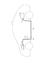
図1に示すようにワイヤハーネス10は、2個又は3個以上の電気機器(機器)を電気的に接続するものであって、例えば、ハイブリッド車や電気自動車等の車両Vの前部に設置されたインバータ11と、そのインバータ11よりも車両Vの後方に設置された高圧バッテリ12とを電気的に接続する。ワイヤハーネス10は、例えば、車両Vの床下等を通るように配索され、その一端がコネクタC1を介してインバータ11に接続され、他端がコネクタC1を介して高圧バッテリ12に接続される。インバータ11は、車両走行の動力源となる車輪駆動用のモータ(図示略)と接続される。インバータ11は、高圧バッテリ12の直流電力から交流電力を生成し、その交流電力をモータに供給する。高圧バッテリ12は、例えば、百ボルト以上の電圧を供給可能なバッテリである。
図2に示すように、ワイヤハーネス10は、電線部材20を備え、該電線部材20は、芯線21と該芯線21の外周を被覆する絶縁被覆22とを有する複数本(本実施形態では2本)の電線23と、該電線23の外周を包囲する電磁シールド部材であって複数の金属素線が編成された編組部材24とを備える。なお、本実施形態の編組部材24を構成する金属素線の材料は、アルミニウム系金属材料が用いられている。
また、図1に示すように、ワイヤハーネス10は、前記電線部材20が挿通される種々のまたは一連の外装部材としての金属パイプ25とプロテクタ26とコルゲートチューブ27とを備える。金属パイプ25は、高圧バッテリ12から延びて車両Vの床下に配索される電線部材20を覆うように設けられている。プロテクタ26は、金属パイプ25よりもインバータ11側の電線部材20の屈曲部位を覆うように設けられている。コルゲートチューブ27は、プロテクタ26とインバータ11との間の電線部材20を覆うように設けられている。
そして、図2に示すように、プロテクタ26には、電線部材20の延在方向に直交する直交方向に開口した開口部30と、互い違いに逆方向に延出する第1及び第2の通路片31,32を有して前記開口部30とプロテクタ26の外部とを連通する迷路構造の排出部33とが設けられている。
詳しくは、まず開口部30は、車両Vに固定された状態でプロテクタ26の底部から重力方向(図2中、下方向)に向かって開口している。そして、排出部33は、開口部30における車両後方側(図2中、右側)の端部から僅かに下方に延びた後方延設部34と、該後方延設部34の先端から車両前方側(図2中、左側)に延びる前記第1の通路片31とを有する。また、排出部33は、開口部30における車両前方側(図2中、左側)の端部から下方に延びた前方延設部35と、該前方延設部35の先端から車両後方側(図2中、右側)に延びる前記第2の通路片32とを有する。第2の通路片32は、第1の通路片31の下方に配置されて第1の通路片31とともに迷路構造を構成する。また、排出部33は、前記開口部30における車両幅方向(図2中、紙面直交方向)の両端部から下方に延びて前記第1及び第2の通路片31,32の側方を塞ぐ側壁36を有する。また、本実施形態の第1及び第2の通路片31,32は、車両に固定された状態でそれぞれ重力方向に傾斜して延出している。また、本実施形態の開口部30の電線部材20側の端部(すなわち開口部30の開口縁)には断面R形状の面取り部37が形成されている。
また、プロテクタ26の一端部(図示した例では、プロテクタ26の開口端縁)と該一端部から導出された電線部材20との間は、プロテクタ26の一端部の外周と電線部材20の外周とに亘って巻回されるテープ38によって閉塞されている。
次に、上記のように構成されたワイヤハーネス10の作用について説明する。
例えば、車両Vの走行中等では、回転するタイヤによる跳ね上げや走行風等によって地面の砂等の異物が舞い上げられてワイヤハーネス10に掛かることがある。そして、何らかの経路からプロテクタ26と電線部材20との間に砂等の異物が入り込むこともあるが、それら異物は主に開口部30から下方の第1の通路片31上に落ちて、更に第1の通路片31の先端部と前記前方延設部35との間から下方の第2の通路片32上に落ちて、更に第2の通路片32の先端部すなわち異物出口39からプロテクタ26の外部に排出される。
例えば、車両Vの走行中等では、回転するタイヤによる跳ね上げや走行風等によって地面の砂等の異物が舞い上げられてワイヤハーネス10に掛かることがある。そして、何らかの経路からプロテクタ26と電線部材20との間に砂等の異物が入り込むこともあるが、それら異物は主に開口部30から下方の第1の通路片31上に落ちて、更に第1の通路片31の先端部と前記前方延設部35との間から下方の第2の通路片32上に落ちて、更に第2の通路片32の先端部すなわち異物出口39からプロテクタ26の外部に排出される。
次に、上記実施形態の効果を以下に記載する。
(1)プロテクタ26には、電線部材20の延在方向に直交する直交方向に開口した開口部30と、互い違いに逆方向に延出する第1及び第2の通路片31,32を有して開口部30とプロテクタ26の外部とを連通する迷路構造の排出部33とが設けられる。よって、排出部33から砂等の異物がプロテクタ26の内部に入り込み難い構造としながら、プロテクタ26と電線部材20との間に入り込んだ異物を排出することができる。よって、電線部材20が砂等の異物と長期的に擦れ合って傷付くといったことが防止され、電線部材20を良好に保護することができる。
(1)プロテクタ26には、電線部材20の延在方向に直交する直交方向に開口した開口部30と、互い違いに逆方向に延出する第1及び第2の通路片31,32を有して開口部30とプロテクタ26の外部とを連通する迷路構造の排出部33とが設けられる。よって、排出部33から砂等の異物がプロテクタ26の内部に入り込み難い構造としながら、プロテクタ26と電線部材20との間に入り込んだ異物を排出することができる。よって、電線部材20が砂等の異物と長期的に擦れ合って傷付くといったことが防止され、電線部材20を良好に保護することができる。
(2)第1及び第2の通路片31,32は、車両に固定された状態でそれぞれ重力方向に傾斜して延出するため、砂等の異物がプロテクタ26の外部に排出され易くなる。
(3)開口部30の電線部材20側の端部には面取り部37が形成されるため、開口部30の電線部材20側の端部に電線部材20が擦れて傷付くことが防止される。
(3)開口部30の電線部材20側の端部には面取り部37が形成されるため、開口部30の電線部材20側の端部に電線部材20が擦れて傷付くことが防止される。
本実施形態は、以下のように変更して実施することができる。本実施形態及び以下の変更例は、技術的に矛盾しない範囲で互いに組み合わせて実施することができる。
・上記実施形態では、排出部33の後方延設部34は開口部30における車両後方側の端部から下方に延び、前方延設部35は開口部30における車両前方側の端部から下方に延びるとしたが、これに限定されず、変更してもよい。すなわち、上記実施形態では、開口部30の範囲とプロテクタ26の外面における排出部33の内面の範囲とが同じとなるように構成されるとしたが、開口部をプロテクタ26の外面における排出部33の内面の範囲よりも小さく形成してもよい。
・上記実施形態では、排出部33の後方延設部34は開口部30における車両後方側の端部から下方に延び、前方延設部35は開口部30における車両前方側の端部から下方に延びるとしたが、これに限定されず、変更してもよい。すなわち、上記実施形態では、開口部30の範囲とプロテクタ26の外面における排出部33の内面の範囲とが同じとなるように構成されるとしたが、開口部をプロテクタ26の外面における排出部33の内面の範囲よりも小さく形成してもよい。
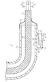
具体的には、例えば、図3に示すように、変更してもよい。この例では、開口部40の前後方向の幅が後方延設部34と前方延設部35との前後方向の間隔よりも小さく形成され、開口部40はプロテクタ26の外面における排出部33の内面の範囲よりも小さく形成されている。なお、この例では、開口部40は、プロテクタ26の外面における排出部33の内面の前後方向の範囲の中央に形成されている。
このようにすると、砂等の異物が排出部33内から開口部40を介してプロテクタ26の内部に入り込み難くなる。例えば、プロテクタ26と電線部材20との間に入り込んだ砂等の異物が開口部40から排出部33に落ちると、その異物が開口部40を介してプロテクタ26と電線部材20との間に逆流し難くなる。
・上記実施形態の排出部33には、開口部30,40側から外部側に向かう外力によって排出部33を開状態とする扉部を設けてもよい。
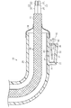
具体的には、例えば、図4に示すように、変更してもよい。この例では、上記別例(図3参照)の後方延設部34の先端に、薄肉のヒンジ部41を介して板状の扉部42が回動可能に設けられている。扉部42は、外力が掛かっていない状態で下方に延びるように配置されて、第2の通路片32の先端部と当接して排出部33を閉状態とする。また、扉部42は、例えば、砂等の異物が開口部40側から外部に向かって移動して扉部42に接触して押すことで、第2の通路片32の先端部から離間して排出部33を開状態とする(図4中、2点鎖線参照)。
具体的には、例えば、図4に示すように、変更してもよい。この例では、上記別例(図3参照)の後方延設部34の先端に、薄肉のヒンジ部41を介して板状の扉部42が回動可能に設けられている。扉部42は、外力が掛かっていない状態で下方に延びるように配置されて、第2の通路片32の先端部と当接して排出部33を閉状態とする。また、扉部42は、例えば、砂等の異物が開口部40側から外部に向かって移動して扉部42に接触して押すことで、第2の通路片32の先端部から離間して排出部33を開状態とする(図4中、2点鎖線参照)。
このようにすると、砂等の異物によって扉部42に開口部40側から外部側に向かう外力が掛かったときのみ開状態となり砂等の異物が排出可能となる。そして、扉部42に開口部40側から外部側に向かう外力が掛かっていないときの閉状態では外部側から開口部40側に砂等の異物が侵入することが防止される。
・上記実施形態では、排出部33の外部に開口する外部開口部は、車両後方に向かって開口している構成としたが、これに限定されず、他の方向に向かって開口している構成としてもよい。
例えば、図5に示すように、排出部33の外部に開口する外部開口部43は、車両Vに固定された状態で重力方向に向かって開口している(言い換えると重力方向にのみ開口し水平方向には開口していない)構成としてもよい。この例では、上記実施形態(図2参照)の排出部33における後方延設部34の更に車両後方側(図5中、右側)にプロテクタ26の外周から下方に延びる壁部44が形成されている。壁部44は、第2の通路片32の下端と同じ位置まで下方に延び、前記側壁36は壁部44まで連続して形成されている。そして、第2の通路片32の下端と側壁36の下端と壁部44の下端とで形成される外部開口部43が、車両Vに固定された状態で重力方向に向かって開口するように構成されている。
このようにすると、水平方向から飛んでくる砂等の異物が外部開口部43を介して排出部33内に入り込まないようにすることができる。
・上記実施形態では、第1及び第2の通路片31,32は、車両に固定された状態でそれぞれ重力方向に傾斜して延出するとしたが、これに限定されず、いずれか一方のみ重力方向に傾斜して延出するように構成してもよいし、いずれも重力方向に傾斜していない構成としてもよい。
・上記実施形態では、第1及び第2の通路片31,32は、車両に固定された状態でそれぞれ重力方向に傾斜して延出するとしたが、これに限定されず、いずれか一方のみ重力方向に傾斜して延出するように構成してもよいし、いずれも重力方向に傾斜していない構成としてもよい。
・上記実施形態では、開口部30の電線部材20側の端部には断面R形状の面取り部37が形成されるとしたが、これに限定されず、例えば、傾斜面状の面取り部としてもよいし、面取り部を形成しなくてもよい。
・上記実施形態では、排出部33は、第1及び第2の通路片31,32を有するとしたが、互い違いに逆方向に延出する少なくとも2つの通路片を有していれば、通路片の数は3つ以上としてもよい。
・上記実施形態では、電線部材20は、電線23と編組部材24とを備えるとしたが、少なくとも電線23を備えていれば、他の構成の電線部材としてもよい。例えば、編組部材24は他の構成の電磁シールド部材としてもよいし、電磁シールド部材を備えていない電線部材(電線23のみ)としてもよい。また、上記実施形態の編組部材24を構成する金属素線の材料は、アルミニウム系金属材料が用いられているとしたが、銅系金属材料等を用いてもよい。
・上記実施形態では、電線部材20の電線23を2本としたが、これに限定されず、1本としてもよいし、3本以上としてもよい。
・上記実施形態では、電線部材20が挿通される外装部材の1つであるプロテクタ26に開口部30,40及び排出部33を設けた例としたが、金属パイプ25やコルゲートチューブ27等の他の外装部材に同様に開口部及び排出部を設けて実施してもよい。また、上記実施形態では、外装部材として金属パイプ25とプロテクタ26とコルゲートチューブ27とを備えるとしたが、勿論、全てを備えている必要はなく、例えば、外装部材として金属パイプ25を備えていない構成や、金属パイプ25とプロテクタ26とを備えていない構成、すなわちコルゲートチューブ27のみを備えた構成としてもよい。また、勿論、上記のように配置された外装部材(金属パイプ25とプロテクタ26とコルゲートチューブ27)はそれぞれ他の外装部材に変更してもよく、例えば金属パイプ25を外装部材としての樹脂パイプに変更してもよい。
・上記実施形態では、電線部材20が挿通される外装部材の1つであるプロテクタ26に開口部30,40及び排出部33を設けた例としたが、金属パイプ25やコルゲートチューブ27等の他の外装部材に同様に開口部及び排出部を設けて実施してもよい。また、上記実施形態では、外装部材として金属パイプ25とプロテクタ26とコルゲートチューブ27とを備えるとしたが、勿論、全てを備えている必要はなく、例えば、外装部材として金属パイプ25を備えていない構成や、金属パイプ25とプロテクタ26とを備えていない構成、すなわちコルゲートチューブ27のみを備えた構成としてもよい。また、勿論、上記のように配置された外装部材(金属パイプ25とプロテクタ26とコルゲートチューブ27)はそれぞれ他の外装部材に変更してもよく、例えば金属パイプ25を外装部材としての樹脂パイプに変更してもよい。
・車両におけるインバータ11と高圧バッテリ12の配置関係は、上記実施形態に限定されるものではなく、車両構成に応じて適宜変更してもよい。
例えば、図6に示すように、高圧バッテリ12が車両Vの床の略全体に配置され、その高圧バッテリ12とインバータ11とを電気的に接続するワイヤハーネス10に具体化してもよい。なお、この例(図6参照)では、外装部材としての金属パイプ25を備えておらず、高圧バッテリ12から前記プロテクタ26までの間はコルゲートチューブ27が設けられている。
例えば、図6に示すように、高圧バッテリ12が車両Vの床の略全体に配置され、その高圧バッテリ12とインバータ11とを電気的に接続するワイヤハーネス10に具体化してもよい。なお、この例(図6参照)では、外装部材としての金属パイプ25を備えておらず、高圧バッテリ12から前記プロテクタ26までの間はコルゲートチューブ27が設けられている。
・上記実施形態では、ワイヤハーネス10によって接続される電気機器としてインバータ11及び高圧バッテリ12を採用したが、これに限定されない。例えば、インバータ11と車輪駆動用のモータとを接続するワイヤハーネスに採用してもよい。すなわち、車両に搭載される電気機器間を電気的に接続するものであれば適用可能である。
・図示した例の開口部30,40および第1の通路片31は、砂粒などの固形異物がそこに落ちるように構成されたピットの代表例である。
・図示した例の開口部30,40、第1の通路片31、第2の通路片32、排出部33、後方延設部34、前方延設部35、側壁36、異物出口39、外部開口部43、および壁部44のすべてまたは一部は、固形異物排出構造の代表例である。
・図示した例の開口部30,40、第1の通路片31、第2の通路片32、排出部33、後方延設部34、前方延設部35、側壁36、異物出口39、外部開口部43、および壁部44のすべてまたは一部は、固形異物排出構造の代表例である。
本開示は以下の実装例を包含する。限定のためでなく理解の補助として実施形態の構成要素の参照符号を付した。
[付記1]本開示の一または複数の実装例に従うワイヤハーネス(10)は、
シールドまたはノンシールド電線(20)を挿通させるための内部空間を形成する外周壁と、前記シールドまたはノンシールド電線(20)がそこから導出される開口端縁とを有する筒状外装部材(26)と、
前記筒状外装部材(26)の前記外周壁において前記筒状外装部材(26)の前記開口端縁とは異なる軸方向位置に設けられ、前記筒状外装部材(26)の前記内部空間内の固形異物を、前記筒状外装部材(26)の前記内部空間から排出するのを促進するように構成された固形異物排出構造(30、40、31、32、33、34、35、36、39、43、44)とを備えることができる。
[付記1]本開示の一または複数の実装例に従うワイヤハーネス(10)は、
シールドまたはノンシールド電線(20)を挿通させるための内部空間を形成する外周壁と、前記シールドまたはノンシールド電線(20)がそこから導出される開口端縁とを有する筒状外装部材(26)と、
前記筒状外装部材(26)の前記外周壁において前記筒状外装部材(26)の前記開口端縁とは異なる軸方向位置に設けられ、前記筒状外装部材(26)の前記内部空間内の固形異物を、前記筒状外装部材(26)の前記内部空間から排出するのを促進するように構成された固形異物排出構造(30、40、31、32、33、34、35、36、39、43、44)とを備えることができる。
[付記2]或る実装例では、前記固形異物は、砂粒などの粒状固形異物であってよい。
[付記3]或る実装例では、前記固形異物排出構造は、
前記固形異物が前記筒状外装部材(26)の前記外周壁の内周面からそこに落ちるように構成されたピット(30、31;40)と、
前記ピット(30;40)に落ちた前記固形異物を固形異物出口(39、43)に向かって移動または転動または落下させるように構成されたジグザクスロープ(31,32)と
を備えることができる。
[付記3]或る実装例では、前記固形異物排出構造は、
前記固形異物が前記筒状外装部材(26)の前記外周壁の内周面からそこに落ちるように構成されたピット(30、31;40)と、
前記ピット(30;40)に落ちた前記固形異物を固形異物出口(39、43)に向かって移動または転動または落下させるように構成されたジグザクスロープ(31,32)と
を備えることができる。
[付記4]或る実装例では、前記ジグザクスロープ(31,32)は、
前記ピット(30、31;40)の底面を形成する第1スロープ(31)と、
前記第1スロープ(31)から下方に離間した第2スロープ(32)と
を備えることができる。
前記ピット(30、31;40)の底面を形成する第1スロープ(31)と、
前記第1スロープ(31)から下方に離間した第2スロープ(32)と
を備えることができる。
[付記5]或る実装例では、前記第1スロープ(31)と前記第2スロープ(32)とは、それらの延出方向および/または傾斜方向が、互い違いであってよい。
[付記6]或る実装例では、
前記第1スロープ(31)は、重力方向に対して、正または負のいずれか一方である第1の符号を有する第1の傾斜角度を有することができ、
前記第2スロープ(32)は、重力方向に対して、正または負のいずれか他方である第2の符号を有する第2の傾斜角度を有することができる。
[付記6]或る実装例では、
前記第1スロープ(31)は、重力方向に対して、正または負のいずれか一方である第1の符号を有する第1の傾斜角度を有することができ、
前記第2スロープ(32)は、重力方向に対して、正または負のいずれか他方である第2の符号を有する第2の傾斜角度を有することができる。
[付記7]或る実装例では、前記ワイヤハーネス(10)は、車両(V)の電気機器(11,12)に電気的に接続されるように構成されており、
前記第1スロープ(31)は、前記車両(V)の前方を向いて傾斜することができ、
前記第2スロープ(32)は、前記車両(V)の後方を向いて傾斜することができる。
前記第1スロープ(31)は、前記車両(V)の前方を向いて傾斜することができ、
前記第2スロープ(32)は、前記車両(V)の後方を向いて傾斜することができる。
[付記8]或る実装例では、前記固形異物出口(39)は、前記車両(V)の後方を向いて開口することができる。
[付記9]或る実装例では、前記ピット(30、40)は、前記筒状外装部材(26)の前記外周壁の前記内周面に開口することができ、
前記ピット(30、40)の開口縁(37)は、面取りされてよい。
[付記9]或る実装例では、前記ピット(30、40)は、前記筒状外装部材(26)の前記外周壁の前記内周面に開口することができ、
前記ピット(30、40)の開口縁(37)は、面取りされてよい。
[付記10]或る実装例では、前記固形異物排出構造は、前記筒状外装部材(26)において重力方向の最下位置に設けられてよい。
[付記11]或る実装例では、前記筒状外装部材(26)は、前記固形異物排出構造を含む合成樹脂のワンピース品であってよい。
[付記11]或る実装例では、前記筒状外装部材(26)は、前記固形異物排出構造を含む合成樹脂のワンピース品であってよい。
本発明がその技術的思想から逸脱しない範囲で他の特有の形態で具体化されてもよいということは当業者にとって明らかであろう。例えば、実施形態(あるいはその1つ又は複数の態様)において説明した部品のうちの一部を省略したり、いくつかの部品を組合せてもよい。本発明の範囲は、添付の請求の範囲を参照して、請求の範囲が権利を与えられる均等物の全範囲と共に確定されるべきである。
10…ワイヤハーネス
20…電線部材
26…プロテクタ(外装部材)
30,40…開口部
31…第1の通路片(通路片)
32…第2の通路片(通路片)
33…排出部
37…面取り部
42…扉部
43…外部開口部
V…車両
20…電線部材
26…プロテクタ(外装部材)
30,40…開口部
31…第1の通路片(通路片)
32…第2の通路片(通路片)
33…排出部
37…面取り部
42…扉部
43…外部開口部
V…車両
Claims (7)
- 電線部材と、
前記電線部材が挿通される外装部材と
を備え、車両に固定されるワイヤハーネスであって、
前記外装部材には、前記電線部材の延在方向に直交する直交方向に開口した開口部と、互い違いに逆方向に延出する少なくとも2つの通路片を有して前記開口部と前記外装部材の外部とを連通する迷路構造の排出部とが設けられたワイヤハーネス。 - 前記通路片の少なくとも1つは、前記車両に固定された状態で重力方向に傾斜して延出した請求項1に記載のワイヤハーネス。
- 前記開口部の前記電線部材側の端部には面取り部が形成された請求項1又は2に記載のワイヤハーネス。
- 前記開口部は、前記外装部材の外面における前記排出部の内面の範囲よりも小さく形成された請求項1~3の何れか1項に記載のワイヤハーネス。
- 前記排出部には、前記開口部側から外部側に向かう外力によって前記排出部を開状態とする扉部が設けられた請求項1~4の何れか1項に記載のワイヤハーネス。
- 前記排出部の外部に開口する外部開口部は、前記車両に固定された状態で重力方向に向かって開口した請求項1~5の何れか1項に記載のワイヤハーネス。
- 電線部材が挿通される外装部材であって、
前記電線部材の延在方向に直交する直交方向に開口した開口部と、互い違いに逆方向に延出する少なくとも2つの通路片を有して前記開口部と前記外装部材の外部とを連通する迷路構造の排出部とが設けられた外装部材。
Applications Claiming Priority (2)
| Application Number | Priority Date | Filing Date | Title |
|---|---|---|---|
| JP2018194087A JP2020062901A (ja) | 2018-10-15 | 2018-10-15 | ワイヤハーネス、及び外装部材 |
| JP2018-194087 | 2018-10-15 |
Publications (1)
| Publication Number | Publication Date |
|---|---|
| WO2020079914A1 true WO2020079914A1 (ja) | 2020-04-23 |
Family
ID=70283053
Family Applications (1)
| Application Number | Title | Priority Date | Filing Date |
|---|---|---|---|
| PCT/JP2019/029410 Ceased WO2020079914A1 (ja) | 2018-10-15 | 2019-07-26 | ワイヤハーネス、及び外装部材 |
Country Status (2)
| Country | Link |
|---|---|
| JP (1) | JP2020062901A (ja) |
| WO (1) | WO2020079914A1 (ja) |
Families Citing this family (3)
| Publication number | Priority date | Publication date | Assignee | Title |
|---|---|---|---|---|
| JP2023087768A (ja) * | 2021-12-14 | 2023-06-26 | 矢崎総業株式会社 | プロテクタ、及び、ワイヤハーネス |
| KR102692796B1 (ko) * | 2022-05-12 | 2024-08-07 | 주식회사 경신 | 와이어 하네스용 콜게이트 튜브 |
| JP2024111465A (ja) * | 2023-02-06 | 2024-08-19 | 住友電装株式会社 | ワイヤハーネス |
Citations (8)
| Publication number | Priority date | Publication date | Assignee | Title |
|---|---|---|---|---|
| JPH0281087U (ja) * | 1988-12-09 | 1990-06-22 | ||
| JPH0578124U (ja) * | 1992-03-18 | 1993-10-22 | 古河電気工業株式会社 | 電気接続箱の排水構造 |
| WO1999001921A1 (fr) * | 1997-07-02 | 1999-01-14 | Mitsubishi Denki Kabushiki Kaisha | Alternateur pour vehicule |
| JP2003047125A (ja) * | 2001-07-31 | 2003-02-14 | Yazaki Corp | 防水ボックスの排水構造 |
| JP2005019069A (ja) * | 2003-06-24 | 2005-01-20 | Sumitomo Wiring Syst Ltd | 電線カバー |
| JP2005304131A (ja) * | 2004-04-08 | 2005-10-27 | Yazaki Corp | ワイヤーハーネスの防水構造及びワイヤーハーネス |
| JP2015002593A (ja) * | 2013-06-14 | 2015-01-05 | 住友電装株式会社 | プロテクタ及びプロテクタ付ワイヤーハーネス |
| JP2016096595A (ja) * | 2014-11-12 | 2016-05-26 | 住友電装株式会社 | 電線保護パイプおよびワイヤハーネス |
-
2018
- 2018-10-15 JP JP2018194087A patent/JP2020062901A/ja active Pending
-
2019
- 2019-07-26 WO PCT/JP2019/029410 patent/WO2020079914A1/ja not_active Ceased
Patent Citations (8)
| Publication number | Priority date | Publication date | Assignee | Title |
|---|---|---|---|---|
| JPH0281087U (ja) * | 1988-12-09 | 1990-06-22 | ||
| JPH0578124U (ja) * | 1992-03-18 | 1993-10-22 | 古河電気工業株式会社 | 電気接続箱の排水構造 |
| WO1999001921A1 (fr) * | 1997-07-02 | 1999-01-14 | Mitsubishi Denki Kabushiki Kaisha | Alternateur pour vehicule |
| JP2003047125A (ja) * | 2001-07-31 | 2003-02-14 | Yazaki Corp | 防水ボックスの排水構造 |
| JP2005019069A (ja) * | 2003-06-24 | 2005-01-20 | Sumitomo Wiring Syst Ltd | 電線カバー |
| JP2005304131A (ja) * | 2004-04-08 | 2005-10-27 | Yazaki Corp | ワイヤーハーネスの防水構造及びワイヤーハーネス |
| JP2015002593A (ja) * | 2013-06-14 | 2015-01-05 | 住友電装株式会社 | プロテクタ及びプロテクタ付ワイヤーハーネス |
| JP2016096595A (ja) * | 2014-11-12 | 2016-05-26 | 住友電装株式会社 | 電線保護パイプおよびワイヤハーネス |
Also Published As
| Publication number | Publication date |
|---|---|
| JP2020062901A (ja) | 2020-04-23 |
Similar Documents
| Publication | Publication Date | Title |
|---|---|---|
| WO2020079914A1 (ja) | ワイヤハーネス、及び外装部材 | |
| JP5722572B2 (ja) | ワイヤハーネス | |
| JP6095062B2 (ja) | 電気接続箱 | |
| CN102473873B (zh) | 电池组 | |
| JP7003651B2 (ja) | 車両 | |
| JP2009067159A (ja) | 車両用空力構造 | |
| JP2020058095A (ja) | ワイヤハーネス | |
| JP2021054232A (ja) | 整流装置 | |
| CN109216971B (zh) | 电力转换装置以及电力转换装置在车辆上的安装结构 | |
| JP2012109629A (ja) | 電子機器 | |
| JP7597064B2 (ja) | 充電インレット装置 | |
| JP7473587B2 (ja) | 電気接続箱 | |
| JP5232208B2 (ja) | 車両用ホーン | |
| US20140354044A1 (en) | Power line protection structure | |
| US11529912B2 (en) | Wire harness | |
| JP5668648B2 (ja) | 車両後部構造 | |
| JP7006560B2 (ja) | ワイヤハーネス、及び外装部材 | |
| CN106573579A (zh) | 车辆的中控台盒中的电磁波屏蔽构造 | |
| JP6354900B2 (ja) | 車両用非接触充電装置 | |
| JP6844495B2 (ja) | 車両機器の配設構造 | |
| CN215475504U (zh) | 取付装置、车篮组件和车辆 | |
| JP4998160B2 (ja) | 車体前部構造 | |
| JP7170370B2 (ja) | ボデープロテクタ、該ボデープロテクタを備えた車両下部構造 | |
| JP3956779B2 (ja) | 電気接続箱 | |
| US11791588B2 (en) | Liquid discharge structure |
Legal Events
| Date | Code | Title | Description |
|---|---|---|---|
| 121 | Ep: the epo has been informed by wipo that ep was designated in this application |
Ref document number: 19874457 Country of ref document: EP Kind code of ref document: A1 |
|
| NENP | Non-entry into the national phase |
Ref country code: DE |
|
| 122 | Ep: pct application non-entry in european phase |
Ref document number: 19874457 Country of ref document: EP Kind code of ref document: A1 |