WO2020075855A1 - 通気アセンブリ及び通気筐体 - Google Patents
通気アセンブリ及び通気筐体 Download PDFInfo
- Publication number
- WO2020075855A1 WO2020075855A1 PCT/JP2019/040314 JP2019040314W WO2020075855A1 WO 2020075855 A1 WO2020075855 A1 WO 2020075855A1 JP 2019040314 W JP2019040314 W JP 2019040314W WO 2020075855 A1 WO2020075855 A1 WO 2020075855A1
- Authority
- WO
- WIPO (PCT)
- Prior art keywords
- ventilation
- ventilation assembly
- protrusion
- housing
- inner member
- Prior art date
- Legal status (The legal status is an assumption and is not a legal conclusion. Google has not performed a legal analysis and makes no representation as to the accuracy of the status listed.)
- Ceased
Links
Images


















Classifications
-
- H—ELECTRICITY
- H05—ELECTRIC TECHNIQUES NOT OTHERWISE PROVIDED FOR
- H05K—PRINTED CIRCUITS; CASINGS OR CONSTRUCTIONAL DETAILS OF ELECTRIC APPARATUS; MANUFACTURE OF ASSEMBLAGES OF ELECTRICAL COMPONENTS
- H05K5/00—Casings, cabinets or drawers for electric apparatus
- H05K5/02—Details
- H05K5/0213—Venting apertures; Constructional details thereof
- H05K5/0216—Venting plugs comprising semi-permeable membranes
-
- B—PERFORMING OPERATIONS; TRANSPORTING
- B29—WORKING OF PLASTICS; WORKING OF SUBSTANCES IN A PLASTIC STATE IN GENERAL
- B29C—SHAPING OR JOINING OF PLASTICS; SHAPING OF MATERIAL IN A PLASTIC STATE, NOT OTHERWISE PROVIDED FOR; AFTER-TREATMENT OF THE SHAPED PRODUCTS, e.g. REPAIRING
- B29C33/00—Moulds or cores; Details thereof or accessories therefor
- B29C33/0033—Moulds or cores; Details thereof or accessories therefor constructed for making articles provided with holes
-
- F—MECHANICAL ENGINEERING; LIGHTING; HEATING; WEAPONS; BLASTING
- F21—LIGHTING
- F21S—NON-PORTABLE LIGHTING DEVICES; SYSTEMS THEREOF; VEHICLE LIGHTING DEVICES SPECIALLY ADAPTED FOR VEHICLE EXTERIORS
- F21S45/00—Arrangements within vehicle lighting devices specially adapted for vehicle exteriors, for purposes other than emission or distribution of light
- F21S45/30—Ventilation or drainage of lighting devices
-
- F—MECHANICAL ENGINEERING; LIGHTING; HEATING; WEAPONS; BLASTING
- F21—LIGHTING
- F21V—FUNCTIONAL FEATURES OR DETAILS OF LIGHTING DEVICES OR SYSTEMS THEREOF; STRUCTURAL COMBINATIONS OF LIGHTING DEVICES WITH OTHER ARTICLES, NOT OTHERWISE PROVIDED FOR
- F21V31/00—Gas-tight or water-tight arrangements
- F21V31/03—Gas-tight or water-tight arrangements with provision for venting
-
- H—ELECTRICITY
- H05—ELECTRIC TECHNIQUES NOT OTHERWISE PROVIDED FOR
- H05K—PRINTED CIRCUITS; CASINGS OR CONSTRUCTIONAL DETAILS OF ELECTRIC APPARATUS; MANUFACTURE OF ASSEMBLAGES OF ELECTRICAL COMPONENTS
- H05K5/00—Casings, cabinets or drawers for electric apparatus
- H05K5/06—Hermetically-sealed casings
- H05K5/068—Hermetically-sealed casings having a pressure compensation device, e.g. membrane
Definitions
- the present invention relates to a ventilation assembly fixedly used in a housing and a ventilation housing to which the ventilation assembly is fixed.
- the inside and outside of the housing for various electronic equipment such as lamps, inverters, converters, ECUs (Electronic Control Units), battery packs, radars, cameras, and other electronic equipment for home use, medical care, office use, etc.
- the ventilation assembly may be fixed to secure the ventilation of the device or reduce the pressure fluctuation inside the housing.
- the ventilation assembly has dust-proof properties that prevent dust from entering the housing, waterproof properties that prevent water from entering, and oil-proof properties that prevent oil from entering, depending on the specific electrical components to be fixed.
- Various properties such as oiliness and CCT resistance for preventing invasion of salt are required.
- Patent Document 1 discloses a ventilation assembly capable of satisfying the breathability and various required properties.
- the ventilation assembly disclosed in Patent Document 1 is shown in FIG.
- the ventilation assembly 101 shown in FIG. 41 includes an inner member 102 that is a tubular body having openings at both ends 108 and 109, and a ventilation membrane 103 that covers the opening at one end 108 of the inner member 102. And an external member 104 that is a cylindrical body at the bottom.
- the outer member 104 is joined to the inner member 102 in a state where the inner member 102 is inserted from the end 108 side inside the outer member 104.
- the outer member 104 includes a protrusion 106 protruding from the inner surface 105 of the bottom in a direction along the central axis of the ventilation assembly 101.
- the protrusion 106 is in contact with the gas permeable membrane 103 arranged at the end 108 of the internal member 102.
- the ventilation assembly 101 includes a space 107 serving as a ventilation path 115 that connects the outside of the ventilation assembly 101 and the ventilation membrane 103, between the inner surface 105 of the bottom of the outer member 104 and the ventilation membrane 103, and the outer peripheral surface of the inner member 102. And the inner peripheral surface of the outer member 104.
- the ventilation assembly 101 is fixed to a cylindrical protrusion 112 that extends from the outer surface of the housing 111 and has a space 110 inside that communicates the inside and outside of the housing 111. More specifically, the ventilation assembly 101 is fixed to the protrusion 112 by inserting the protrusion 112 into the inner member 102 through the opening at the other end 109 of the inner member 102. With the ventilation assembly 101 fixed, ventilation can be performed inside and outside the housing 111 through the protrusion 112 and the ventilation assembly 101.
- the present invention is a ventilation assembly that is fixed to a cylindrical protrusion that extends from the outer surface of a housing and that communicates the inside and the outside of the housing with the inside thereof.
- An object of the present invention is to provide a ventilation assembly capable of preventing damage to the ventilation membrane when fixing.
- the present invention A ventilation assembly fixed to a cylindrical protrusion that extends from the outer surface of the housing and has a first space inside that communicates the inside and outside of the housing,
- An inner member that is a tubular body having openings at both ends, an outer member that is a bottomed tubular body, and a ventilation film that covers the opening at one of the end portions of the inner member,
- the outer member is joined to the inner member in a state where the inner member is inserted from the one end side inside the outer member, At least one selected from inside the internal member, inside the external member, and between the joined internal member and external member serves as a ventilation path that connects the ventilation membrane and the outside of the ventilation assembly.
- the ventilation member wherein the inner member includes one or more first protrusions protruding from the inner circumferential surface at a position on the other end side with respect to the gas permeable membrane, I will provide a.
- the present invention provides A vented housing comprising a housing and a vent assembly, comprising:
- the housing includes a cylindrical protrusion that extends from the outer surface of the housing and has a first space inside that communicates the inside and the outside of the housing,
- the ventilation assembly is the ventilation assembly of the present invention, When the projection is inserted into the internal member from the opening at the other end of the internal member, and the inner peripheral surface of the internal member and the outer peripheral surface of the projection are in contact with each other, the vent assembly is It is fixed to the protrusion,
- the ventilation housing wherein the one or more first protrusions of the ventilation assembly are located between the tip of the protrusion and the gas permeable membrane, I will provide a.
- the inner member of the ventilation assembly according to the present invention has at least one or two or more members protruding from the inner peripheral surface at a position on the other end side with respect to the gas permeable membrane, that is, a position on the end side where the protrusion of the housing is inserted.
- a first protrusion is provided.
- the tip (open end) of the protrusion inserted into the internal member contacts the first protrusion before contacting the gas permeable membrane, and this contact further increases the protrusion relative to the internal member. Insertion is suppressed. Therefore, the ventilation assembly according to the present invention is suitable for preventing damage to the ventilation membrane when fixing the ventilation assembly even when the ventilation assembly is made thin.
- FIG. 1A is a cross-sectional view schematically showing the ventilation assembly according to the first embodiment.
- FIG. 1B is a sectional view schematically showing the ventilation assembly according to the first embodiment.
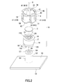
- FIG. 2 is an exploded perspective view schematically showing the ventilation assembly according to the first embodiment.
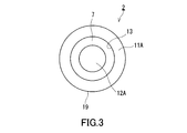
- FIG. 3 is a plan view of an internal member included in the ventilation assembly of the first embodiment, as observed along a central axis of the ventilation assembly.
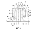
- FIG. 4 is a cross-sectional view schematically showing a modified example of the ventilation assembly of the first embodiment.
- FIG. 5 is an exploded perspective view schematically showing the ventilation assembly of the second embodiment.
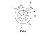
- FIG. 6 is a plan view of an internal member included in the ventilation assembly according to the second embodiment, which is observed along the central axis of the ventilation assembly.
- FIG. 1A is a cross-sectional view schematically showing the ventilation assembly according to the first embodiment.
- FIG. 1B is a sectional view schematically showing the ventilation assembly according to the first embodiment.
- FIG. 2
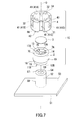
- FIG. 7 is an exploded perspective view schematically showing the ventilation assembly according to the third embodiment.
- FIG. 8A is a sectional view schematically showing the ventilation assembly according to the fourth embodiment.
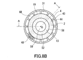
- FIG. 8B is a sectional view schematically showing the ventilation assembly according to the fourth exemplary embodiment.
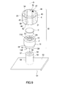
- FIG. 9 is an exploded perspective view schematically showing the ventilation assembly of the fourth embodiment.
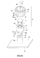
- FIG. 10 is an exploded perspective view schematically showing the ventilation assembly of the fifth embodiment.
- FIG. 11 is an exploded perspective view schematically showing the ventilation assembly according to the sixth embodiment.
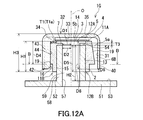
- FIG. 12A is a sectional view schematically showing the ventilation assembly according to the seventh embodiment.
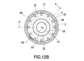
- FIG. 12B is a sectional view schematically showing the ventilation assembly according to the seventh embodiment.
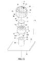
- FIG. 13 is an exploded perspective view schematically showing the ventilation assembly of the seventh embodiment.
- FIG. 14 is an exploded perspective view schematically showing the ventilation assembly according to the eighth embodiment.
- FIG. 15 is an exploded perspective view schematically showing the ventilation assembly of the ninth embodiment.
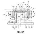
- FIG. 16A is a sectional view schematically showing the ventilation assembly of the tenth embodiment.
- FIG. 16B is a sectional view schematically showing the ventilation assembly of the tenth embodiment.
- FIG. 17 is an exploded perspective view schematically showing the ventilation assembly of the tenth embodiment.
- FIG. 18 is an exploded perspective view schematically showing the ventilation assembly of the eleventh embodiment.
- FIG. 19 is an exploded perspective view schematically showing the ventilation assembly according to the twelfth embodiment.
- FIG. 20A is a sectional view schematically showing the ventilation assembly according to the thirteenth embodiment.
- FIG. 20A is a sectional view schematically showing the ventilation assembly according to the thirteenth embodiment.
- FIG. 20B is a sectional view schematically showing the ventilation assembly according to the thirteenth embodiment.
- FIG. 21 is an exploded perspective view schematically showing the ventilation assembly of the thirteenth embodiment.
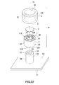
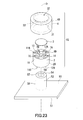
- FIG. 22 is an exploded perspective view schematically showing the ventilation assembly of the fourteenth embodiment.
- FIG. 23 is an exploded perspective view schematically showing the ventilation assembly according to the fifteenth embodiment.
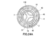
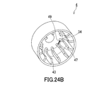
- FIG. 24A is a perspective view schematically showing the ventilation assembly manufactured in the example. 24B is a perspective view schematically showing an external member included in the ventilation assembly of FIG. 24A.
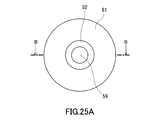
- FIG. 25A is a plan view schematically showing a housing lid used for evaluating the moisture permeability (moisture permeability) of the ventilation housing.
- FIG. 25B is a schematic diagram showing a cross section of the housing lid of FIG. 25A.
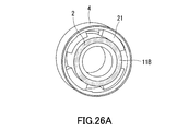
- FIG. 26A is a perspective view schematically showing the ventilation assembly manufactured in the example.
- FIG. 26B is a perspective view schematically showing an external member included in the ventilation assembly of FIG. 26A.
- FIG. 27 is a graph plotting the relationship between the water vapor transmission rate and the ventilation distance for Reference Examples 1 to 6.
- FIG. 28A is a perspective view schematically showing the ventilation assembly manufactured in the example.
- 28B is a perspective view schematically showing an external member included in the ventilation assembly of FIG. 28A.
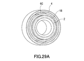
- FIG. 29A is a perspective view schematically showing the ventilation assembly manufactured in the example.
- FIG. 29B is a perspective view schematically showing an external member included in the ventilation assembly of FIG. 29A.
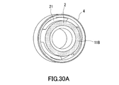
- FIG. 30A is a perspective view schematically showing the ventilation assembly manufactured in the example.
- FIG. 30A is a perspective view schematically showing the ventilation assembly manufactured in the example.
- FIG. 30B is a perspective view schematically showing an external member included in the ventilation assembly of FIG. 30A.
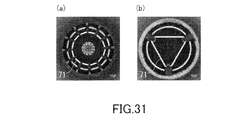
- FIG. 31 is a diagram showing an image used for measuring an area S2 min for the ventilation assembly manufactured in the example.
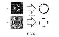
- FIG. 32 is a diagram showing an image used for measuring the area S2 out for the ventilation assembly manufactured in the example.
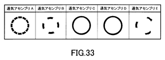
- FIG. 33 is a diagram showing an image after the binarization process used for measuring the area S2 out for the ventilation assembly manufactured in the example.
- FIG. 34 is a graph plotting the relationship between the ratio S2 out / S1 and the water vapor transmission rate for Reference Examples 7 to 11.
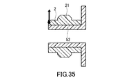
- FIG. 35 is a schematic diagram for explaining the pull-out test of the internal member.
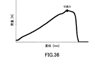
- FIG. 36 is a graph showing the SS curve obtained in the pull-out test of the internal member.
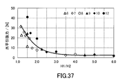
- FIG. 37 is a graph plotting the relationship between the ratio H1 / H2 and the pulling force for a reference example in which the internal member was pulled out without being damaged during the pulling-out test of the internal member.
- FIG. 38 is a graph showing the SS curve obtained in the pull-out test of the external member.
- FIG. 39 is a graph plotting the relationship between the insertion depth of the external member and the pulling force for the reference example.
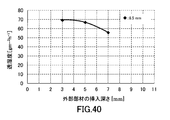
- FIG. 40 is a graph in which the relationship between the insertion depth of the external member and the water vapor transmission rate is plotted for Reference Examples 2 to 4.
- FIG. 41 is a sectional view schematically showing an example of a conventional ventilation assembly.
- the vent assembly of the first aspect of the present disclosure comprises: A ventilation assembly fixed to a cylindrical protrusion that extends from the outer surface of the housing and has a first space inside that communicates the inside and outside of the housing, An inner member that is a tubular body having openings at both ends, an outer member that is a bottomed tubular body, and a ventilation film that covers the opening at one of the end portions of the inner member,
- the outer member is joined to the inner member in a state where the inner member is inserted from the one end side inside the outer member, At least one selected from inside the internal member, inside the external member, and between the joined internal member and external member serves as a ventilation path that connects the ventilation membrane and the outside of the ventilation assembly.
- the inner member includes one or more first protrusions protruding from the inner peripheral surface at a position on the other end side with respect to the gas permeable membrane.
- the internal member in the vent assembly of the first aspect, includes two or more first protrusions, The two or more first protrusions are joined to each other in a space inside the inner member.
- the vent assembly of the first or second aspect in the vent assembly of the first or second aspect, The first protrusion and the gas permeable membrane are separated from each other.
- the height of the internal member is 6.0 mm or more and 10 mm or less.
- the ventilation assembly in the ventilation assembly according to any one of the first to fourth aspects, When observed in a direction perpendicular to the central axis of the ventilation assembly, The length of the portion of the inner member covered by the outer member in the direction along the central axis is 6.0 mm or more and 8.0 mm or less.
- the outer member and / or the inner member has a locking mechanism that detachably joins the outer member and the inner member.
- a ventilation housing comprising a housing and a vent assembly, comprising:
- the housing includes a cylindrical protrusion that extends from the outer surface of the housing and has a first space inside that communicates the inside and the outside of the housing,
- the ventilation assembly is the ventilation assembly according to any one of the first to sixth aspects, When the projection is inserted into the internal member from the opening at the other end of the internal member, and the inner peripheral surface of the internal member and the outer peripheral surface of the projection are in contact with each other, the vent assembly is It is fixed to the protrusion, The one or more first protrusions of the ventilation assembly are located between the tip of the protrusion and the breathable membrane.
- the ventilation housing in the ventilation housing according to the seventh aspect, The cross-sectional area S1 of the first space cut by a plane perpendicular to the central axis of the protrusion and the cross-sectional area of the second space cut by a plane perpendicular to the ventilation direction as the ventilation path
- the ratio S2 min / S1 to the total area S2 min at the position where the total area totaled for each distance from the film is the minimum is 1.0 or more.
- the ventilation housing in the ventilation housing according to the seventh or eighth aspect, When the cross-sectional area S1 of the first space cut by a plane perpendicular to the central axis of the protrusion and the second space from the other end side along the central axis of the ventilation assembly are observed. , The ratio S2 out / S1 of the total area S2 out of the plane representing the cross section at the position where the second space is the narrowest is 1.0 or more.
- FIGS. 1A and 1B show a cross-section BB of the ventilation assembly 1A shown in FIG. 1A.
- FIG. 1A shows a cross section AOA of the ventilation assembly 1A shown in FIG. 1B.
- the “O” in FIG. 1B is the central axis of vent assembly 1A. 1A and 1B, the ventilation assembly 1A is fixed to the projection 52 of the housing 51, in other words, the vicinity of the projection 52 in the ventilation housing in which the ventilation assembly 1A is fixed to the projection 52 of the housing 51, It is shown.
- An exploded perspective view of the ventilation assembly 1A shown in FIGS. 1A and 1B is shown in FIG. As shown in FIG.
- the ventilation assembly 1A has a tubular shape having a first space 59 inside which extends from the outer surface 53 of the housing 51 and extends and communicates the inside and outside of the housing 51. It is fixed to the protrusion 52.
- the ventilation assembly 1A includes an inner member 2, a gas permeable membrane 3, and an outer member 4.
- the inner member 2 is a tubular body having openings 12A and 12B at both ends 11A and 11B.
- the inner member 2 has an open tube structure in which both ends are open.
- the gas permeable membrane 3 is arranged at the one end 11A of the inner member 2 so as to cover the opening 12A at the one end 11A.
- the outer member 4 is a cylindrical body having a bottom.
- the outer member 4 has a closed pipe structure in which one end 42 is an opening and the other end is a closed end closed by the bottom 32.
- the outer member 4 is joined to the inner member 2 in a state where the inner member 2 is inserted inside the outer member 4 from the side of the end portion 11A where the gas permeable membrane 3 is arranged.
- the inner side of the outer member 4 means a space surrounded by the opening of the outer member 4 and the inner peripheral surface 31.
- the external member 4 functions as a cover member that protects the gas permeable membrane 3 from foreign matter such as dust and water flying from the outside.
- the ventilation assembly 1A has a second space 5 serving as a ventilation path that connects the ventilation film 3 and the outside of the ventilation assembly 1A. Further, the ventilation assembly 1A has a space 5a, which is a part of the second space 5, between the outer peripheral surface 40 of the outer member 4 joined to the inner member 2 and the inner peripheral surface 13 of the inner member 2. are doing.
- the ventilation assembly 1A has a space 5a between the joined inner member 2 and outer member 4, more specifically, between the inner peripheral surface 31 of the outer member 4 and the outer peripheral surface 19 of the inner member 2. There is. Further, in the ventilation assembly 1A, the inner surface 33 of the bottom portion 32 of the outer member 4 and the ventilation film 3 are separated from each other.
- the ventilation assembly 1A also has a space 5b that is a part of the second space 5 between the inner surface 33 and the ventilation film 3 that are separated from each other.
- the “ventilation path” is a path through which gas can move between the ventilation membrane and the outside of the ventilation assembly. For example, air that has permeated the ventilation membrane 3 and reached the space 5b passes from the space 5b to the space 5a. It means a path of gas that can finally reach the outside of the ventilation assembly 1A. Therefore, a space such as the space 5a can be a "ventilation path" not only between the joined inner member 2 and outer member 4 but also inside the inner member 2 or inside the outer member 4. Note that the ventilation path is determined as a reference for the one formed when the outer member 4 is inserted into the inner member 2 as far as possible.
- the protrusion 52 is inserted into the inner member 2 through the opening 12B at the other end 11B of the inner member 2, and the inner peripheral surface 13 of the inner member 2 and the outer peripheral surface 58 of the protrusion 52 are in contact with each other. Is fixed to the protrusion 52 of the housing 51.
- the ventilation assembly 1A is fixed, the protrusion 52 is inserted into the through hole 14 of the inner member 2.
- the through hole 14 is a space that is surrounded by the inner peripheral surface 13 of the internal member 2 and that connects the end portion 11A and the end portion 11B.
- the housing is provided via the first space 59 inside the projection 52, the through hole 14 of the internal member 2, the ventilation film 3, and the second space 5. Ventilation inside and outside 51 can be secured.
- the inner member 2 protrudes from the inner peripheral surface 13 at a position on the other end 11B side with respect to the gas permeable membrane 3, that is, a side where the protrusion 52 is inserted when fixing.
- the projection 7 is provided.
- the tips 54 of the protrusions 52 inserted into the inner member 2 come into contact with the first protrusions 7 before coming into contact with the gas permeable membrane 3, and this contact prevents further insertion of the protrusions 52 into the inner member 2. Therefore, even when the ventilation assembly 1A is thin, it is possible to prevent the ventilation film 3 from being damaged when being fixed to the protrusion 52.
- the height H1 of the internal member 2 which is the distance between the end 11A and the end 11B of the internal member 2 along the central axis O, is, for example, 3.0 to 13.0 mm.
- the upper limit of the height H1 may be 11.0 mm or less, 10.0 mm or less, 9.5 mm or less, 9.0 mm or less, and further 8.5 mm or less.
- the lower limit of the height H1 may be 3.5 mm or more, 4.0 mm or more, 5.0 mm or more, 6.0 mm or more, 6.5 mm or more, 7.0 mm or more, and further 7.5 mm or more.
- the height H1 of the inner member 2 may be 6.0 mm or more and 10 mm or less.
- the central axis O of the ventilation assembly 1A is, more specifically, the central axis of the internal member 2.
- the central axis of the inner member 2 and the central axis of the protrusion 52 usually coincide with each other.
- the thickness T1 of the inner member 2 which is the distance between the inner peripheral surface 13 and the outer peripheral surface 19 of the inner member 2, is, for example, 0.5 to 3.0 mm.
- the lower limit of the thickness T1 may be 0.6 mm or more, 0.7 mm or more, 0.8 mm or more, and further 0.9 mm or more.
- the upper limit of the thickness T1 may be 2.5 mm or less, 2.0 mm or less, 1.5 mm or less, and further 1.2 mm or less.
- the ventilation assembly 1A can be made thin, but sufficient strength as the inner member 2 is ensured.
- the outer member 4 is joined to the inner member 2. It is possible to prevent the internal member 2 from being damaged or torn when it is pressed.
- the thickness T1 is determined based on the state before the internal member 2 is inserted into the protrusion 52.
- the thickness T1 is reduced from the end portion 11B into which the protrusion 52 is inserted when fixing the ventilation assembly 1A to a certain height in the direction along the central axis O. It has a thin portion 15.
- the inner member 2 has a step 16 at the boundary between the thin portion 15 and the other portions. The step 16 is located farther from the outer surface 53 of the housing 51 than the opening-side end 42 of the external member 4 (located above the ventilation assembly 1A as compared to the end 42).
- the position of the step 16 is not limited to this example. According to the internal member 2 having the thin portion 15, the ventilation assembly 1A can be more easily inserted into the protrusion 52 of the housing 51.
- This effect is particularly advantageous when the inner member 2 has a small inner diameter due to thinning or the like, in other words, when the end portion 11B of the inner member 2 is difficult to spread when being fixed to the protrusion 52. Further, the inner member 2 does not have the thin portion 15 on the side of the end portion 11A on which the gas permeable membrane 3 is arranged, so that both members 2, 4 when the outer member 4 is joined to the inner member 2 are formed. It is possible to prevent an inclination between them and an inclination of the internal member 2 when the internal member 2 is inserted into the protrusion 52 of the housing 51. This effect is particularly advantageous when the thickness T1 of the internal member 2 is small due to thinning or the like. In the examples shown in FIGS.
- the peripheral surface of the thin portion 15 in the step 16 and the outer peripheral surface 19 are connected by a surface perpendicular to the central axis O.
- the surface connecting the peripheral surface of 15 and the outer peripheral surface 19 may be inclined with respect to the direction perpendicular to the central axis O.
- the height H1 of the inner member 2 is smaller than the height H2 of the protrusion 52, which is the distance from the outer surface 53 of the housing 51 to the tip 54 of the protrusion 52.
- the merit of obtaining the above-described effect based on the first protrusion 7 becomes particularly large.
- the ventilation assembly 1A may be inserted in an inclined state with respect to the protrusion 52, the above effect is obtained even when the relationship between the heights H1 and H2 in the ventilation assembly and the ventilation housing is other than the above. Is obtained.
- the ratio H1 / H2 of the height H1 of the inner member 2 to the height H2 of the protrusion 52 may be 0.20 or more and 1.70 or less.
- the lower limit of the ratio H1 / H2 may be 0.40 or more, 0.60 or more, 0.80 or more, 1.00 or more, 1.05 or more, and even 1.10 or more.
- the upper limit of the ratio H1 / H2 is 1.60 or less, 1.50 or less, 1.40 or less, 1.30 or less, 1.25 or less, 1.22 or less, 1.20 or less, 1.18 or less, 1. It may be 16 or less, further 1.14 or less.
- the ventilation assembly and the ventilation housing having the ratio H1 / H2 in the above range can effectively prevent the ventilation assembly from falling off the protrusion of the housing.
- the ventilation assembly 1A is used by being inserted into the protrusion 52 from the opening 12B in the other end 11B of the internal member 2, and the judgment is made on the basis of the state in which the protrusion 52 is inserted as
- the internal member 2 and the protrusion 52 of the first embodiment are both cylindrical. Since the material forming the inner member 2 is usually an elastic body, the diameter of the inner peripheral surface 13 of the inner member 2 is usually less than or equal to the diameter of the outer peripheral surface 58 of the protrusion 52.
- the elastic modulus of the elastic member forming the inner member 2 and / or the diameter of the inner peripheral surface 13 of the inner member 2 may be, for example, the ease of inserting the inner member 2 into the protrusion 52, the housing 51-the ventilation assembly 1A. It can be set in consideration of the sealing property between them. Further, the shape of the inner member 2 that is a tubular body and the shape of the protrusion 52 that is a tubular shape are not limited to a cylinder.
- the inner diameter of the cylindrical inner member 2 is, for example, 6.0 to 13.0 mm.
- the lower limit of the inner diameter may be 6.5 mm or more, 7.0 mm or more, 7.5 mm or more, and further 8.0 mm or more.
- the upper limit of the inner diameter may be 12.5 mm or less, 12.0 mm or less, 11.5 mm or less, and further 11.0 mm or less.
- the inner member 2 which is a cylinder, half the value obtained by subtracting the inner diameter from the outer diameter corresponds to the thickness T1.
- the external member 4 is a bottomed cylinder.
- a part of the peripheral wall 37 projects toward the inside of the outer member 4, more specifically, toward the central axis O. Due to the protrusion of the peripheral wall 37, the outer member 4 is provided with a plurality of grooves 41 (41A, 41B, 41C, 41D) extending along the central axis O on the outer peripheral surface 40.
- the grooves 41 are provided at equal intervals in the circumferential direction of the external member 4 when observed along the central axis O, and the opening side of the external member 4 is provided. From the end 42 to the bottom 32.
- the thickness of the peripheral wall 37 is substantially equal in the groove 41 portion and other portions of the outer member 4.
- the position where the groove 41 is provided on the outer peripheral surface 40, the interval between the adjacent grooves 41, the direction in which the groove 41 extends, and the section where the groove 41 extends between the end 42 and the bottom 32 of the external member 4 are: It is not limited to the above example. Further, the thickness of the peripheral wall 37 may be different between the groove 41 and other portions.
- the inner peripheral surface 31 of the outer member 4 in the groove 41 coincides with the peripheral surface of a virtual cylinder A centered on the central axis O.
- the inner member 2 and the outer member 4 are joined to each other by the outer peripheral surface 19 and the inner peripheral surface 31 in the groove 41 contacting each other. Since the material forming the inner member 2 is usually an elastic body, the diameter of the virtual cylinder A is usually equal to or less than the diameter of the outer peripheral surface 19.
- a gap 6A between the inner peripheral surface 31 of the outer member 4 and the outer peripheral surface 19 of the inner member 2 in the portion other than the groove 41 is a part of the space 5a.
- the outer peripheral surface 19 of the inner member 2 does not have a protruding portion protruding from the surface 19.
- the outer peripheral surface 19 constitutes a cylindrical peripheral surface over the entire circumference thereof.
- the length D8 of the portion of the inner member 2 covered by the outer member 4 along the central axis O is, for example, 3.5 mm or more and 9.5 mm or less. It may be 6.0 mm or more and 8.0 mm or less.
- the lower limit of the length D8 may be 4.0 mm or more, 4.5 mm or more, and further 5.0 mm or more.
- the upper limit of the length D8 may be 9.0 mm or less, 8.5 mm or less, and further 8.0 mm or less.
- the length D8 is in these ranges, the inner member 2 and the outer member 4 are more reliably joined to each other, and for example, when the ventilation assembly 1A is fixed to the protrusion 52 of the housing 51, the inner member 2 moves to the outer member. 4 becomes difficult to detach. In addition, it becomes possible to secure sufficient moisture permeability. Furthermore, foreign matter such as dust and water can be suppressed from entering the second space 5 from the outside of the ventilation assembly 1A.
- the length D8 is determined based on the state where the outer member 4 is inserted into the inner member 2 as far as possible.
- the length (inner / outer contact length) D4 in the direction along the central axis O where the outer peripheral surface 19 of the inner member 2 and the inner peripheral surface 31 of the groove 41 of the outer member 4 are in contact is, for example, 4.0. Is about 8.0 mm.
- the lower limit of the length D4 may be 4.5 mm or more, 5 mm or more, and further 5.5 mm or more.
- the upper limit of the length D4 may be 7.5 mm or less, 7 mm or less, and further 6.5 mm or less.
- the gas permeable membrane 3 is arranged in the portion of the inner member 2 that is in contact with the inner peripheral surface 31 of the outer member 4 in the direction along the central axis O. It extends from the end portion 11A to the step 16, more specifically, to the lower end of the portion other than the thin portion 15. In addition, this portion extends over the entire outer circumferential surface 19 in the circumferential direction.
- the distance D6 in the direction along the central axis O between the end portion (lower end) 42 on the opening side of the outer member 4 and the end portion 11B of the inner member 2 is, for example, 0.1 to 3.0 mm, and is 0. It may be 5 to 2.5 mm, further 1.0 to 2.0 mm. When the distance D6 is within these ranges, the joint between the inner member 2 and the outer member 4 becomes stronger. The distance D6 is determined based on the state where the outer member 4 is inserted into the inner member 2 as far as possible.
- the external member 4 includes two or more second protrusions 34 that protrude from the inner surface 33 of the bottom portion 32 in the direction along the central axis O.
- Each of the second protrusions 34 also protrudes from the inner peripheral surface 31 of the outer member 4 toward the central axis O when observed along the central axis O.
- the second projection 34 and the end 11A of the inner member 2 are brought into contact with each other, so that the inner surface 33 of the bottom portion 32 of the outer member 4 is separated from the gas permeable membrane 3.
- the second protrusion 34 is provided so as to come into contact with the gas permeable membrane 3 in a state where the outer member 4 and the inner member 2 are joined, or so as to come into contact with both the inner member 2 and the gas permeable membrane 3. Good.
- the internal member 2 includes one first protrusion 7.
- the first projecting portion 7 projects into the internal space of the internal member 2. More specifically, the first protrusion 7 projects in the direction of the central axis O. Further, the first protrusion 7 protrudes from a part of the inner peripheral surface 13 of the inner member 2 in the height direction.
- the first protrusion when observed along the central axis O, projects from the entire inner peripheral surface 13 (100%) of the inner member 2.
- the first protrusion 7 has a ring shape when observed along the central axis O.
- the first protrusion 7 may be in the shape of a ring that is partially cut off.
- the first protrusion 7 may protrude from 75% or more, preferably 80% or more, and more preferably 90% or more of the inner peripheral surface 13 of the inner member 2 when observed along the central axis O. .
- excessive insertion of the protrusion 52 can be more reliably suppressed.
- the ventilation assembly 1A is inserted in a state of being inclined with respect to the protrusion 52, excessive insertion of the protrusion 52 can be more reliably suppressed.
- the thickness T3 of the first protrusion 7 in the direction along the central axis O is, for example, 0.8 to 1.1 mm, and may be 0.7 to 1.5 mm. When the thickness T3 of the first protrusion 7 is within these ranges, it is possible to more reliably prevent the excessive insertion of the protrusion 52.
- the first protrusion 7 of the inner member 2 is located at the end 11B side with respect to the gas permeable membrane 3.
- the position of the first protrusion 7 in the inner member 2 can be set, for example, according to the depth at which the protrusion 52 is to be inserted into the inner member 2 when fixing the ventilation assembly 1A.
- the length D5 in the direction along the central axis O between the end 11B of the inner member 2 and the lower surface of the first protrusion 7 is, for example, 70 to 98% of the height H1 of the inner member 2. , 75 to 95%, and further 80 to 90%.
- the first protrusion 7 and the gas permeable membrane 3 are separated from each other.
- the first protrusion 7 pressed by the tip 54 may bend toward the end 11A. If the first protrusion 7 and the gas permeable membrane 3 are separated from each other, it is possible to suppress deformation and damage of the gas permeable membrane 3 due to the bending of the first protrusion 7.
- the first protrusion 7 and the ventilation film 3 may be in contact with each other.
- FIG. 4 shows a modification of the first embodiment in which the first protrusion 7 and the gas permeable membrane 3 are in contact with each other.
- the ventilation assembly 1A and the ventilation housing shown in FIG. 4 are the same as the ventilation assembly 1A and the ventilation housing shown in FIGS. 1A, 1B and 2 except that the first protrusion 7 and the ventilation membrane 3 are in contact with each other. It has the same structure as the body.
- the distance between them is, for example, 0 to 1.0 mm, 0.1 to 0.9 mm, and further 0.2 to 0.8 mm. May be
- the distance D2 from the axis O to the inner peripheral surface 57 of the protrusion 52 is equal.
- the distance D1 is equal to or less than the distance D2 in order to more reliably prevent the protrusion 52 from being excessively inserted. May be.
- Ventilation which is the distance between an imaginary plane perpendicular to the central axis O passing through the lowermost point in the ventilation assembly 1A and an imaginary plane perpendicular to the central axis O passing through the uppermost point.
- the height H3 of the assembly 1A is, for example, 5.0 to 12 mm.
- the upper limit of the height H3 may be 11 mm or less, 10.5 mm or less, 10 mm or less, and further 9.5 mm or less.
- the lower limit of the height H3 may be 7.5 mm or more, 8.0 mm or more, 8.5 mm or more, and further 9 mm or more.
- the height H3 is determined based on the state in which the outer member 4 is inserted into the inner member 2 as far as possible. In the example shown in FIGS. 1A, 1B and 2, the lowermost point is located at the end 11B of the inner member 2 and the uppermost point is located at the outer surface 35 of the bottom 32 of the outer member 4.
- the cross-sectional area S1 of the first space 59 cut by a plane perpendicular to the central axis of the protrusion 52 may be 5 mm 2 or more and 60 mm 2 or less.
- the lower limit of the area S1 may be 10 mm 2 or more, 12 mm 2 or more, 14 mm 2 or more, and further 16 mm 2 or more.
- the upper limit of the area S1 may be 50 mm 2 or less, 40 mm 2 or less, 30 mm 2 or less, and further 20 mm 2 or less.
- the central axis of the protrusion 52 usually coincides with the central axis O of the ventilation assembly 1A.
- the ratio S2 min / S1 of the sectional area S2 min of the second space 5 to the sectional area S1 of the first space 59 is, for example, 0. 8 or more.
- the lower limit of the ratio S2 min / S1 may be 1.0 or higher, 1.1 or higher, 1.2 or higher, 1.3 or higher, and even 1.4 or higher.
- the upper limit of the ratio S2 min / S1 is, for example, 3.0 or less, and may be 2.5 or less, further 2.0 or less.
- the ventilation assembly and the ventilation housing having the ratio S2 min / S1 in the above range have excellent breathability and / or moisture permeability.
- the area S1 is the area of the cross section of the first space 59 taken along a plane perpendicular to the central axis of the protrusion 52.
- the area S2 min is the total area of the cross section at the position where the total area obtained by summing the areas of the cross section of the second space 5 cut by the plane perpendicular to the ventilation direction as the ventilation path for each distance from the ventilation membrane is the minimum. is there.
- the “ventilation path” is a path through which gas can move between the ventilation membrane and the outside of the ventilation assembly, and the “ventilation direction” is the gas in each position when the second space is considered as the ventilation path. It means the direction of travel. Therefore, the ventilation direction differs depending on the position of the second space.
- total area totaled for each distance from the gas permeable membrane is a group of positions where the distance from the gas permeable membrane (when the gas permeable membrane has a point-symmetrical shape, the distance from the center of the gas permeable membrane) is the same. It means that the cross-sectional areas of the second space 5 are summed and considered as the total area. Then, the area S2 min represents the total area of the position where the area value is the minimum of the total area. Further, the area S2 min is determined based on the state where the outer member 4 is inserted into the inner member 2 as far as possible. In the example shown in FIGS.
- the cross section having the area S2 min is the circumferential end of the second protrusion 34 and the portion of the groove 41 where the inner member 2 and the outer member 4 are in contact with each other. It is located between the portion 46, the inner surface 33 of the bottom 32 of the outer member 4 and the end 11A of the inner member 2 (see cross section 47 in FIG. 2). However, in FIG. 2, a part of the cross section having the area S2 min (only the cross section 47 located between one second protrusion 34 and one end 46) is shown. Since the cross section having the area S2 min exists between each of the four second protrusions 34 and the eight ends 46, eight times the area of the cross section 47 corresponds to the area S2 min .
- the area S2 min can be evaluated by, for example, the method described in the examples.
- the ratio S2 out / S1 of the sectional area S2 out of the second space 5 to the sectional area S1 of the first space 59 is, for example, 0. It may be 8 or more, 1.0 or more, 1.2 or more, 1.3 or more, 1.5 or more, 1.8 or more, 2.0 or more, and even 2.2 or more.
- the upper limit of the ratio S2 out / S1 is, for example, 4.0 or less, and may be 3.0 or less.
- the ventilation assembly and the ventilation housing having the ratio S2 out / S1 in the above range have excellent breathability and / or moisture permeability.
- the area S2 out is the narrowest of the second spaces 5 that can be visually recognized when observing the second space 5 from the other end 11B side along the central axis of the ventilation assembly 1A. It is the total area of the plane that represents the cross section at the position. Further, the area S2 out is determined based on the state where the outer member 4 is inserted into the inner member 2 as far as possible. In the example shown in FIGS. 1A, 1B and 2, the cross section having the area S2 out is located between the inner peripheral surface 31 of the outer member 4 and the outer peripheral surface 19 of the inner member 2 (see the cross section 48 of FIG. 1B). ). However, in FIG.
- the cross section having the area S2 out (only the cross section 48 located between the pair of adjacent grooves 41C and 41D) is shown. Since the cross section having the area S2 out is located between the four grooves 41, four times the area of the cross section 48 corresponds to the area S2 out .
- the area S2 out can be evaluated by, for example, the method described in the examples.
- Resins with relatively high hygroscopicity such as polyamide, polycarbonate, and polybutylene terephthalate, may be used in the housing of electrical components and electronic devices.
- a case using such a resin absorbs water vapor in the surroundings, but the absorbed water vapor is released by heat from a heat source inside the case or heat from the outside such as sunlight, and a part of it is released.
- Stay inside the housing It is desirable that the accumulated water vapor inside the housing be quickly discharged to the outside of the housing via the protrusion 52 and the ventilation assembly 1A in order to prevent the inside of the housing from becoming cloudy.
- the ventilation assembly and / or the ventilation housing having excellent moisture permeability, for example, it is possible to suppress fogging inside the housing or to promote elimination of the fogging generated inside the housing.
- the height H2 of the protrusion 52 of the housing 51 is, for example, 8.0 to 12.0 mm.
- the lower limit of the height H2 may be 8.2 mm or more, 8.4 mm or more, 8.6 mm or more, and further 8.8 mm or more.
- the upper limit of the height H2 is 11.8 mm or less, 11.6 mm or less, 11.4 mm or less, and further 11.2 mm or less.
- the length D5 corresponds to the height of the portion of the inner member 2 that covers the protrusion 52 when the first protrusion 7 of the inner member 2 and the tip 54 of the protrusion 52 are in contact with each other.
- the length D5 is, for example, 3.0 to 9.0 mm.
- the upper limit of the length D5 may be 8.5 mm or less, 8.0 mm or less, and further 7.0 mm or less.
- the lower limit of the length D5 may be 3.5 mm or more, 4 mm or more, and further 4.5 mm or more. When the length D5 is within these ranges, the ventilation assembly 1A is less likely to fall off the protrusion 52 of the housing 51.
- the ventilation film 3 is a film that allows gas (typically air) to pass through in the thickness direction and prevents the penetration of foreign matter. Therefore, the ventilation assembly 1A can ensure ventilation inside and outside the housing 51 and prevent foreign matter such as dust, water, oil, and salt from entering the inside of the housing 51.
- the shape of the gas permeable membrane 3 is a circle.
- the shape of the gas permeable membrane 3 is not limited to a circle, and can be selected according to the shape of the portion of the internal member 2 where the gas permeable membrane 3 is arranged, and may be, for example, a polygonal shape.
- the gas permeable membrane 3 is arranged on the end surface of the end portion 11A of the internal member 2.
- the position where the ventilation film 3 is arranged in the ventilation assembly and the ventilation housing of the present invention is not limited to the end surface of the end portion 11A as long as the ventilation film 3 covers the opening 12A of the end portion 11A.
- the ventilation membrane 3 a woven cloth, a non-woven cloth, a mesh or a net made of resin or metal, or a resin porous membrane can be used.
- the gas permeable membrane 3 is not limited as long as it can permeate gas and prevent permeation of foreign matter such as liquid.
- the gas permeable membrane 3 in which a porous resin film and a reinforcing layer having gas permeability are laminated is used.
- the strength of the gas permeable membrane 3 can be improved by the reinforcing layer.
- the resin porous membrane is, for example, a fluororesin porous body and a polyolefin porous body which can be produced by a known stretching method or extraction method.
- the fluororesin is, for example, polytetrafluoroethylene (PTFE), polychlorotrifluoroethylene, tetrafluoroethylene-hexafluoropropylene copolymer, tetrafluoroethylene-perfluoroalkyl vinyl ether copolymer, tetrafluoroethylene-ethylene copolymer. It is united.
- Monomers constituting the polyolefin are, for example, ethylene, propylene and 4-methylpentene-1,1 butene, and a polyolefin which is a homopolymer or copolymer of these monomers can be used for the gas permeable membrane 3.
- a nanofiber film porous body using polyacrylonitrile, nylon, or polylactic acid may be used for the gas permeable membrane 3.
- a PTFE porous body that can ensure air permeability in a small area and has a high ability to prevent foreign matter from entering the inside of the housing 51.
- the average pore diameter of the PTFE porous body is preferably 0.01 ⁇ m or more and 10 ⁇ m or less.
- the reinforcing layer is, for example, a woven fabric, a non-woven fabric, a mesh, a net, a sponge, a foam, or a porous body made of resin or metal.
- the resin porous membrane and the reinforcing layer can be laminated by a method such as adhesive lamination, heat lamination, heat welding, ultrasonic welding, or adhesion with an adhesive.
- the breathable membrane 3 may be liquid-repellent treated.
- the liquid repellent treatment of the gas permeable film 3 can be carried out by applying a liquid repellent agent containing a substance having a small surface tension to the gas permeable film and drying the coating film formed by the coating.
- the liquid repellent contains, for example, a polymer having a perfluoroalkyl group as the above substance.
- the liquid repellent agent can be applied by, for example, an air spray method, an electrostatic spray method, a dip coating method, a spin coating method, a roll coating method, a curtain flow coating method, an impregnation method, or the like.
- the thickness of the gas permeable membrane 3 can be adjusted in the range of, for example, 1 ⁇ m or more and 5 mm or less in consideration of strength and easiness of fixing to the internal member 2.
- the air permeability of the gas permeable membrane 3 is, for example, 0. 0 as the air permeability (Gurley air permeability) measured according to the air permeability measurement method B (Gurley type method) defined in Japanese Industrial Standard (JIS) L1096. 1 to 300 seconds / 100 mL.
- the ventilation membrane 3 may be joined to the internal member 2.
- the gas permeable membrane 3 can be joined to the inner member 2 by various welding methods such as a heat welding method, an ultrasonic welding method, and a laser welding method.
- the gas permeable membrane 3 may be bonded to the inner member 2 with an adhesive or a pressure sensitive adhesive.
- the gas permeable membrane 3 may be arranged at the end 11 ⁇ / b> A of the internal member 2 by insert molding the gas permeable membrane 3 together with the internal member 2.
- the material forming the internal member 2 is usually an elastic body.
- the material forming the outer member 4 is typically a resin. These members can be formed by known molding methods such as injection molding, compression molding and powder molding. Molding of the inner member 2 and the outer member 4 by injection molding is preferable because the mass productivity of the ventilation assembly 1A can be improved.
- the elastic body that can form the inner member 2 is, for example, an elastomer (elastic resin).
- the elastomer may be rubber.
- the elastomer is, for example, nitrile rubber (NBR), ethylene-propylene rubber (EPDM), silicone rubber, fluororubber, acrylic rubber, hydrogenated rubber, and various thermoplastic elastomers.
- the resin that can form the external member 4 is, for example, a thermoplastic resin or the elastomer described above.
- the thermoplastic resin is, for example, polyamide (PA) such as nylon, polybutylene terephthalate (PBT), polyethylene terephthalate (PET), polyphenylene sulfide (PPS), polycarbonate (PC), polypropylene (PP), and polyphenylene ether (PPE).
- PA polyamide
- PBT polybutylene terephthalate
- PET polyethylene terephthalate
- PPS polyphenylene sulfide
- PC polycarbonate
- PP polypropylene
- PPE polyphenylene ether
- the inner member 2 and the outer member 4 may be made of the same material.
- the elastic body forming the inner member 2 and / or the resin forming the outer member 4 includes pigments such as carbon black and titanium white; reinforcing fillers such as glass particles and glass fibers; and additives such as water repellents. May be included. At least a part of the surface of the inner member 2 and / or the outer member 4 may be subjected to a liquid repellent treatment.
- the liquid-repellent treatment can be carried out by the above-mentioned method for the liquid-repellent treatment of the gas permeable membrane 3, an electrodeposition coating method, a film formation by plasma polymerization or the like.
- the inner member 2 and / or the outer member 4 may include a locking mechanism that detachably joins the inner member 2 and the outer member 4.
- the locking mechanism includes, for example, a claw portion, a screw portion, a fitting portion, and the like.
- the housing 51 is made of, for example, resin, metal, or a composite material thereof.
- the protrusion 52 is also the same.
- the resin forming the protrusions 52 is usually not an elastic body.
- the resin forming the protrusion 52 is, for example, a thermoplastic resin (excluding an elastic body) or a thermosetting resin.
- the thermoplastic resin is, for example, the various thermoplastic resins exemplified above as the resin that can form the external member 4, acrylonitrile-butadiene-styrene copolymer resin (ABS), or the like.
- the configuration of the housing 51 is not limited as long as it includes the protrusion 52.
- FIG. 5 shows an exploded perspective view of the ventilation assembly 1B of the second embodiment and the vicinity of the projection 52 in the ventilation housing in which the ventilation assembly 1B is fixed to the projection 52 of the housing 51.
- the ventilation assembly 1 ⁇ / b> B is fixed to a tubular protrusion 52 that extends from the outer surface 53 of the housing 51 and extends, and has a space 59 inside that communicates the inside and outside of the housing 51.
- the ventilation assembly 1B of the second embodiment is the same as the ventilation assembly 1A of the first embodiment except that the number and shape of the first protrusions 7 included in the internal member 2 are different. Description that overlaps with the first embodiment will be omitted.
- the internal member 2 includes two or more first protrusions 7.
- the interval between two or more first protrusions 7A, 7B adjacent to each other is 2 or more.
- the angle ⁇ formed by the straight lines 61A and 61B passing through the central axis O and the ends 62A and 62B of the first protrusions 7A and 7B is 45 degrees or less.
- the ends 62A, 62B of the first protrusions 7A, 7B are observed along the central axis O, and a straight line passing through the central axis O and the gap between the first protrusions 7A, 7B is used as the central axis.
- the straight line is defined as a portion of the first protrusions 7A and 7B that first come into contact with each other.
- the angle ⁇ is preferably 30 degrees or less, more preferably 15 degrees or less.
- Each of the first protrusions 7 shown in FIGS. 5 and 6 projects into the internal space of the internal member 2. More specifically, each of the first protrusions 7 projects in the direction of the central axis O.
- each of the first protrusions 7 has a shape in which, when observed along the central axis O, the width thereof continuously decreases from the inner peripheral surface 13 of the inner member 2 in the direction of the central axis O. are doing.
- the inner member 2 shown in FIGS. 5 and 6 includes six first protrusions 7.
- the number of the first protrusions 7 in the second embodiment is, for example, 2 to 8, and may be 3 to 6.
- FIG. 7 shows an exploded perspective view of the ventilation assembly 1C of the third embodiment and the vicinity of the projection 52 in the ventilation housing in which the ventilation assembly 1C is fixed to the projection 52 of the housing 51.
- the ventilation assembly 1 ⁇ / b> C is fixed to a cylindrical protrusion 52 that extends from the outer surface 53 of the housing 51 and extends, and has a space 59 inside that communicates the inside and outside of the housing 51.
- the ventilation assembly 1C of the third embodiment is the same as the ventilation assembly 1A of the first embodiment, except that the number and shape of the first protrusions 7 included in the internal member 2 are different. Description that overlaps with the first embodiment will be omitted.
- the internal member 2 includes two or more first protrusions 7 (7A, 7B, 7C).
- Each of the first protrusions 7 projects into the internal space of the internal member 2.
- the first protrusions 7A, 7B, 7C are joined to each other in the internal space of the internal member 2.
- the first protrusions 7A, 7B, 7C joined to each other form a bridge connecting two or more regions on the inner peripheral surface 13 of the inner member 2 to each other.
- the rigidity of the internal member 2 can be improved by the first protrusion 7.
- the inner member 2 shown in FIG. 7 includes three first protrusions 7.
- the number of the first protrusions 7 in the third embodiment is, for example, 3-5.
- FIGS. 8A and 8B show a cross section BB of the ventilation assembly 1D shown in FIG. 8A.
- 8A shows a cross section AOA of the ventilation assembly 1D shown in FIG. 8B.
- 8A and 8B show a state in which the ventilation assembly 1D is fixed to the protrusion 52 of the housing 51, in other words, the vicinity of the protrusion 52 in the ventilation housing in which the ventilation assembly 1D is fixed to the protrusion 52 of the housing 51, It is shown.
- An exploded perspective view of the ventilation assembly 1D shown in FIGS. 8A and 8B is shown in FIG.
- the ventilation assembly 1D has a cylindrical projection 52 that has a space 59 that extends from the outer surface 53 of the housing 51 and extends and that communicates the inside and outside of the housing 51 inside. Fixed against.
- the ventilation assembly 1D of the fourth embodiment is the same as the ventilation assembly 1A of the first embodiment except that the shape of the external member 4 is different. Description that overlaps with the first embodiment will be omitted.
- the outer member 4 of the ventilation assembly 1D is a bottomed cylinder, and when observed along the central axis O, two or more third protrusions that protrude from the inner peripheral surface 31 toward the inner side of the outer member 4.
- Each of the third protrusions 43 extends from the opening-side end 42 of the external member 4 to the bottom 32.
- the extending direction of each third protrusion 43 is the direction along the central axis O. Further, each third protrusion 43 is connected to the second protrusion 34 at the bottom 32.
- the direction in which the third protrusion 43 extends and the section in which the third protrusion 43 extends between the end 42 and the bottom 32 are not limited to the above example. Further, the third protrusion 43 and the second protrusion 34 may not be connected, and the external member 4 has the second protrusion 34 and the third protrusion 43 which are independent of each other. May be.
- the inner member 2 and the outer member 4 in the fourth embodiment are joined to each other by the outer peripheral surface 19 of the inner member 2 and the tip end surface 44 of the third protrusion 43 of the outer member 4 contacting each other. Further, in the examples shown in FIGS. 8A, 8B, and 9, the tip surface 44 of the third protrusion 43 coincides with the peripheral surface of the virtual cylinder C centered on the central axis O. Since the material forming the inner member 2 is usually an elastic body, the diameter of the virtual cylinder C is usually equal to or smaller than the diameter of the outer peripheral surface 19.
- each third protrusion 43 is the peripheral surface of the virtual cylinder C. Does not have to match.
- the gap 6B between the inner peripheral surface 31 of the outer member 4 and the outer peripheral surface 19 of the inner member 2 is a part of the space 5a. 8A, 8B and 9, each gap 6B is surrounded by the inner peripheral surface 31, the outer peripheral surface 19 and the third protrusion 43.
- the outer member 4 shown in FIGS. 8A, 8B, and 9 includes twelve third protrusions 43.
- the number of the third protrusions 43 in the fourth embodiment is, for example, 6 to 16.
- the cross section having the area S2 min includes the tips 49 of the adjacent second protrusions 34 on the side of the central axis O and the inner surface 33 of the bottom 32 of the outer member 4. And the end portion 11A of the inner member 2 (see the cross section 47 of FIG. 9).
- a part of the cross section having the area S2 min is shown. Since the cross section having the area S2 min exists between the twelve second protrusions 34, 12 times the area of the cross section 47 corresponds to the area S2 min .
- the cross section having the area S2 out is located between the inner peripheral surface 31 of the outer member 4, the outer peripheral surface 19 of the inner member 2, and the third protruding portion 43. (See cross section 48 in FIG. 8B). However, in FIG. 8B, a part of the cross section having the area S2 out (only the cross section 48 located between the pair of adjacent third protrusions 43) is shown. Since the cross section having the area S2 out is located between the twelve second protrusions 34, 12 times the area of the cross section 48 corresponds to the area S2 out .
- FIG. 10 shows an exploded perspective view of the ventilation assembly 1E of the fifth embodiment and the vicinity of the projection 52 in the ventilation housing in which the ventilation assembly 1E is fixed to the projection 52 of the housing 51.
- the ventilation assembly 1 ⁇ / b> E is fixed to a cylindrical projection 52 that extends from the outer surface 53 of the housing 51 and extends, and has a space 59 inside that communicates the inside and outside of the housing 51.
- the ventilation assembly 1E of the fifth embodiment is the same as the ventilation assembly 1D of the fourth embodiment, except that the ventilation assembly 1E includes the same first protrusion 7 as that of the second embodiment and the external member 4 has the claw 45. Description that overlaps with the second embodiment and the fourth embodiment will be omitted.
- the third protrusion 43 of the outer member 4 has the protruding claw 45 that projects toward the inside of the outer member 4, more specifically, in the direction of the central axis O. It has at the end of the side.
- the claw 45 is locked to the step 16 of the inner member 2 and functions as the locking mechanism described above.
- the inner member 2 and the outer member 4 can be joined more reliably.
- the ventilation assembly 1E is fixed to the protrusion 52 of the housing 51, the inner member 2 It is possible to prevent the external member 4 from falling off.
- the outer member 4 may not have the claw 45, in which case the ventilation assembly 1E includes the same first protrusion 7 as that of the second embodiment. This is the same as the ventilation assembly 1D of the fourth embodiment.
- FIG. 11 shows an exploded perspective view of the ventilation assembly 1F of the sixth embodiment and the vicinity of the projection 52 in the ventilation housing in which the ventilation assembly 1F is fixed to the projection 52 of the housing 51.
- the ventilation assembly 1 ⁇ / b> F is fixed to a cylindrical protrusion 52 that has a space 59 that extends from the outer surface 53 of the housing 51 and extends and that communicates the inside and outside of the housing 51 inside.
- the ventilation assembly 1F of the sixth embodiment is the same as the ventilation assembly 1D of the fourth embodiment, except that the ventilation assembly 1F of the sixth embodiment includes the same first protrusions 7 as those of the third embodiment. Description that overlaps with the third embodiment and the fourth embodiment will be omitted.
- FIGS. 12A and 12B show a cross section BB of the ventilation assembly 1G shown in FIG. 12A.
- FIG. 12A shows a cross section AOA of the ventilation assembly 1G shown in FIG. 12B. 12A and 12B, a state in which the ventilation assembly 1G is fixed to the protrusion 52 of the housing 51, in other words, the vicinity of the protrusion 52 in the ventilation housing in which the ventilation assembly 1G is fixed to the protrusion 52 of the housing 51, It is shown.
- An exploded perspective view of the ventilation assembly 1G shown in FIGS. 12A and 12B is shown in FIG.
- the ventilation assembly 1G includes a cylindrical projection 52 having a space 59 inside which extends from the outer surface 53 of the housing 51 and extends and communicates the inside and outside of the housing 51. Fixed against.
- the ventilation assembly 1G of the seventh embodiment is the same as the ventilation assembly 1D of the fourth embodiment except that the shape of the internal member 2 is different. Description that overlaps with the fourth embodiment will be omitted.
- the thickness T1 of the inner member 2 in the ventilation assembly 1 is more specific as it goes from the upper end (end 11A) to the lower end (end 11B) of the inner member 2 in the state where the outer member 4 is not joined.
- the inner member 2 has a slope extending downward as an outer peripheral surface 19 as a result of the increase from the end 11A to the step 16 with the thin portion 15. (See FIG. 13) ).
- the thickness T1 continuously increases from the upper end of the inner member 2 toward the lower end thereof, more specifically, from the end 11A to the step 16.
- the state of the increase is not limited to the above example, and for example, it may be increased intermittently or there may be a decreased portion. In the example shown in FIG.
- the outer peripheral surface 19 of the inner member 2 constitutes a peripheral surface of a truncated cone whose diameter increases from the upper end toward the lower end. Further, in a state where the outer member 4 is joined (see FIGS. 12A and 12B), each third protrusion 43 of the outer member 4 abuts on the outer peripheral surface 19 of the inner member 2 made of an elastic body. While compressing the part, it bites into the outer peripheral surface 19, and the tip end surface 44 thereof enters the inside of the inner member 2 compared to the position of the outer peripheral surface 19 in the state where the outer member 4 is not joined.
- each of the third protrusions 43 bites into the outer peripheral surface 19 at the portion in contact with the outer peripheral surface 19 of the inner member 2 increases from the bottom portion 32 of the outer member 4 toward the end portion 42. From the upper end (end 11A) to the lower end (end 11B). According to the combination of the inner member 2 and the outer member 4 having the above-described shapes, it is possible to increase the downward compression rate between both members in the portion where the inner member 2 and the outer member 4 are in contact with each other. The outer member 4 can be joined to the inner member 2 more reliably.
- the direction of the force acting on the inner member 2 by the joining of the outer member 4 is the direction perpendicular to the surface of the slope, that is, the outer surface of the housing 51. Since the inner member 2 is pressed toward the 53 side, the ventilation assembly 1A can be more reliably prevented from falling off the projection 52.
- the thickness T1 (T1a) of the inner member 2 at the end portion 11A may be in the range of T1 described above, in which case the ventilation assembly 1G can be made thin. Also, sufficient strength as the internal member 2 is secured.
- FIG. 14 shows an exploded perspective view of the ventilation assembly 1H of the eighth embodiment and the vicinity of the projection 52 in the ventilation housing in which the ventilation assembly 1H is fixed to the projection 52 of the housing 51.
- the ventilation assembly 1H is fixed to a cylindrical protrusion 52 which has a space 59 inside which extends from the outer surface 53 of the housing 51 and extends and which communicates the inside and outside of the housing 51.
- the ventilation assembly 1H of the eighth embodiment is the same as the ventilation assembly 1G of the seventh embodiment, except that the ventilation assembly 1H of the eighth embodiment includes the same first protrusions 7 as those of the second embodiment. Description that overlaps with the second and seventh embodiments will be omitted.
- FIG. 15 shows an exploded perspective view of the ventilation assembly 1J of the ninth embodiment and the vicinity of the projection 52 in the ventilation housing in which the ventilation assembly 1J is fixed to the projection 52 of the housing 51.
- the ventilation assembly 1 ⁇ / b> J is fixed to a cylindrical projection 52 that has a space 59 that extends from the outer surface 53 of the housing 51 and extends and that communicates the inside and outside of the housing 51 inside.
- the ventilation assembly 1J of the ninth embodiment is the same as the ventilation assembly 1G of the seventh embodiment, except that the ventilation assembly 1J of the ninth embodiment includes the same first protrusions 7 as those of the third embodiment. Description that overlaps with the third embodiment and the seventh embodiment will be omitted.
- FIGS. 16A and 16B A ventilation assembly 1K of the tenth embodiment is shown in FIGS. 16A and 16B.
- 16B shows a cross-section BB of the ventilation assembly 1K shown in FIG. 16A. 16A and 16B, a state in which the ventilation assembly 1K is fixed to the protrusion 52 of the housing 51, in other words, the vicinity of the protrusion 52 in the ventilation housing in which the ventilation assembly 1K is fixed to the protrusion 52 of the housing 51, It is shown.
- An exploded perspective view of the ventilation assembly 1K shown in FIGS. 16A and 16B is shown in FIG.
- the ventilation assembly 1K has a cylindrical projection 52 that has a space 59 that extends from the outer surface 53 of the housing 51 and extends and that communicates the inside and outside of the housing 51 inside. Fixed against.
- the ventilation assembly 1K of the tenth embodiment is the same as the ventilation assembly 1A of the first embodiment except that the shapes of the inner member 2 and the outer member 4 are different. Description that overlaps with the first embodiment will be omitted.
- the inner member 2 of the ventilation assembly 1K has ribs 18 extending in the circumferential direction on the outer peripheral surface 19.
- the inner member 2 and the outer member 4 are joined by abutting the outer peripheral surface 19 of the inner member 2 and the inner peripheral surface 31 of the outer member 4. Since the material forming the inner member 2 is usually an elastic body, the diameter of the inner peripheral surface 31 of the outer member 4 is usually less than or equal to the diameter of the outer peripheral surface 19 of the inner member 2. Further, in a state where the inner member 2 and the outer member 4 are joined, the rib 18 is in contact with the opening-side end of the outer member 4.
- a gap 6C is provided inside the peripheral wall 37 of the external member 4.
- the gap 6C is a part of the space 5a.
- a part of the peripheral wall 37 of the external member 4 closer to the central axis O than the gap 6C is divided into a plurality of beam portions 39 by a plurality of slits 38 extending in the direction along the central axis O.
- Each second protrusion 34 of the outer member 4 is connected to the upper end of each beam 39. With such a shape, the weight of the external member 4 and the ventilation assembly 1K can be reduced.
- the cross section having the area S2 min has the tips 49 of the adjacent second protrusions 34 on the side of the central axis O and the inner surface 33 of the bottom 32 of the outer member 4. And the end 11A of the inner member 2 (see cross section 47 in FIG. 17).
- a part of the cross section having the area S2 min is shown. Since the cross section having the area S2 min exists between the eight second protrusions 34, eight times the area of the cross section 47 corresponds to the area S2 min .
- the cross section having the area S2 out corresponds to the cross section of the gap 6C cut by the plane perpendicular to the central axis O (see the cross section 48 of FIG. 16B).
- FIG. 18 shows an exploded perspective view of the ventilation assembly 1L of the eleventh embodiment and the vicinity of the projection 52 in the ventilation housing in which the ventilation assembly 1L is fixed to the projection 52 of the housing 51.
- the ventilation assembly 1 ⁇ / b> L is fixed to a cylindrical protrusion 52 that has a space 59 that extends from the outer surface 53 of the housing 51 and extends and that communicates the inside and outside of the housing 51 inside.
- the ventilation assembly 1L of the eleventh embodiment is the same as the ventilation assembly 1K of the tenth embodiment, except that the ventilation assembly 1L of the eleventh embodiment is provided with the same first protrusion 7. Description that overlaps with the second and tenth embodiments will be omitted.
- FIG. 19 shows an exploded perspective view of the ventilation assembly 1M of the twelfth embodiment and the vicinity of the projection 52 in the ventilation housing in which the ventilation assembly 1M is fixed to the projection 52 of the housing 51.
- the ventilation assembly 1M is fixed to a cylindrical projection 52 that extends from the outer surface 53 of the housing 51 and extends, and has a space 59 inside that communicates the inside and outside of the housing 51 inside.
- the ventilation assembly 1M of the twelfth embodiment is the same as the ventilation assembly 1K of the tenth embodiment, except that the ventilation assembly 1M of the twelfth embodiment is provided with the same first protrusions 7 as those of the third embodiment. Description that overlaps with the third embodiment and the tenth embodiment will be omitted.
- FIGS. 20A and 20B A ventilation assembly 1G of the thirteenth embodiment is shown in FIGS. 20A and 20B.
- FIG. 20B shows a cross section BB of the ventilation assembly 1N shown in FIG. 20A.
- 20A shows a cross section AOA of the ventilation assembly 1N shown in FIG. 20B.
- the ventilation assembly 1N is fixed to the protrusion 52 of the housing 51, in other words, the vicinity of the protrusion 52 in the ventilation housing in which the ventilation assembly 1N is fixed to the protrusion 52 of the housing 51, It is shown.
- FIG. 21 shows an exploded perspective view of the ventilation assembly 1N shown in FIGS. 20A and 20B.
- the ventilation assembly 1N has a cylindrical projection 52 having a space 59 inside which extends projecting from the outer surface 53 of the housing 51 and communicates the inside and outside of the housing 51. Fixed against.
- the ventilation assembly 1N of the thirteenth embodiment is the same as the ventilation assembly 1A of the first embodiment except that the shapes of the inner member 2 and the outer member 4 are different. Description that overlaps with the first embodiment will be omitted.
- the inner member 2 of the ventilation assembly 1N is a cylinder.
- the inner member 2 and the outer member 4 are joined by abutting the outer peripheral surface 19 of the inner member 2 and the inner peripheral surface 31 of the outer member 4. Since the material forming the inner member 2 is usually an elastic body, the diameter of the inner peripheral surface 31 of the outer member 4 is usually less than or equal to the diameter of the outer peripheral surface 19 of the inner member 2.
- a gap 6D that connects the end 11A and the end 11B is provided inside the peripheral wall 20 of the internal member 2.
- the gap 6D is a part of the space 5a.
- the inner member 2 shown in FIGS. 20A, 20B and 21 has four gaps 6D.
- the number of gaps 6D in the thirteenth embodiment is, for example, 2-8.
- the cross section having the area S2 min is the cross section of the four gaps 6D cut by the plane perpendicular to the central axis O (see the cross section 47 of FIG. 21).
- a part of the cross section having the area S2 min (only the cross section 47 corresponding to one gap 6D) is shown. Since there are four gaps 6D, four times the area of the cross section 47 corresponds to the area S2 min .
- the cross section having the area S2 out is the cross section of the four gaps 6D cut by the plane perpendicular to the central axis O (see the cross section 48 of FIG. 21).
- a part of the cross section having the area S2 out (only the cross section 48 corresponding to one gap 6D) is shown. Since there are four gaps 6D, four times the area of the cross section 48 corresponds to the area S2 out .
- FIG. 22 shows an exploded perspective view of the ventilation assembly 1P of the eighth embodiment and the vicinity of the protrusion 52 in the ventilation housing in which the ventilation assembly 1P is fixed to the projection 52 of the housing 51.
- the ventilation assembly 1 ⁇ / b> P is fixed to a tubular protrusion 52 that extends from the outer surface 53 of the housing 51 and extends, and has a space 59 that communicates the inside and outside of the housing 51 inside.
- the ventilation assembly 1P of the fourteenth embodiment is the same as the ventilation assembly 1N of the thirteenth embodiment except that the ventilation assembly 1P of the fourteenth embodiment is provided with the same first protrusions 7. Description that overlaps with the second embodiment and the thirteenth embodiment will be omitted.
- FIG. 23 shows an exploded perspective view of the ventilation assembly 1Q of the fifteenth embodiment and the vicinity of the protrusion 52 in the ventilation housing in which the ventilation assembly 1Q is fixed to the protrusion 52 of the housing 51.
- the ventilation assembly 1Q is fixed to a cylindrical protrusion 52 that has a space 59 that extends from the outer surface 53 of the housing 51 and extends and that communicates the inside and outside of the housing 51 inside.
- the ventilation assembly 1Q of the fifteenth embodiment is the same as the ventilation assembly 1N of the thirteenth embodiment, except that it has the same first protrusion 7 as that of the third embodiment. Description that overlaps with the third embodiment and the thirteenth embodiment will be omitted.
- An internal member 2 having the shape shown in FIG. 24A was produced by injection molding using an olefin-based thermoplastic elastomer (Mitsui Chemicals, Inc. Mirastomer (registered trademark), hardness 71, density 880 kg / m 3 ).
- the maximum thickness of the obtained internal member 2 is 2.4 mm, the minimum thickness is 1.1 mm, the outer diameter of the portion having the maximum thickness is 12 mm, the outer diameter of the portion having the minimum thickness is 10 mm, the inner diameter is 7.5 mm, and the height is high.
- the height H1 was 8.0 mm.
- the inner member 2 of FIG. 24A had the same shape as the inner member 2 of FIG.
- An outer member 4 having a shape shown in FIGS. 24A and 24B was produced by injection molding using polypropylene (manufactured by Japan Polypro Co., Ltd.) as a material.
- the maximum thickness of the obtained external member 4 is 2.5 mm, the minimum thickness is 0.6 mm, the outer diameter is 16 mm, the inner diameter of the portion having the maximum thickness is 11.1 mm, and the inner diameter of the portion having the minimum thickness is 13.3 mm.
- the height was 9.0 mm.
- the external member 4 of FIGS. 24A and 24B has the same shape as the external member 4 of FIG. 11 except that it has a claw 45 protruding in the direction of the central axis O at the end of the third protrusion 43 on the end 42 side. Had. 24A and 24B, the inner member 2 and the outer member 4 are viewed from below (the opening side of the outer member 4).
- a laminate of a PTFE stretched porous membrane and a non-woven fabric of PE / PET composite fibers manufactured by Nitto Denko KK, TEMISH "NTF1026-L01", air flow rate: 50 cm 3 / min
- the air-permeable membrane 3 was produced by punching into a 12 mm circle.
- the gas permeable membrane 3 was arranged so as to completely cover the through holes 14 of the inner member 2, and the gas permeable membrane 3 was welded to the inner member 2 by pressure bonding and heating at a temperature of 200 ° C. and a pressure of 20 N for 2 seconds.
- the inner member 2 having the air-permeable membrane 3 welded thereto was press-fitted (inserted) into the outer member 4 to obtain a ventilation assembly.
- FIGS. 25A and 25B A case lid 61 was prepared.
- FIG. 25B shows a cross section BB of FIG. 25A.
- the protrusion 52 had an outer diameter of 8.5 mm, an inner diameter of 5.0 mm, and a height H2 of 8.0 mm.
- the projection 52 of the housing lid 61 is inserted into the opening (opening at the lower end) of the internal member 2 of the ventilation assembly (inserted until the lower end of the internal member 2 contacts the housing 61).
- a housing lid with a ventilation assembly in which the ventilation assembly was fixed to the protrusion 52 was prepared.
- Table 1 shows the results of moisture permeability.
- the "insertion depth of the external member” in Table 1 means the length in the direction along the central axis of the portion of the internal member covered by the external member when observed in the direction perpendicular to the central axis of the ventilation assembly. To do.
- the “inside / outside contact length” means the length along the central axis of the portion where the external member and the internal member are in contact with each other when observed in the direction perpendicular to the central axis of the ventilation assembly.
- the “ventilation distance” means a distance obtained by adding the height H1 of the inner member and the insertion depth of the outer member. "Ventilation distance" substantially corresponds to the distance from the interior of the housing to the outlet of the ventilation assembly.
- FIGS. 26A and 26B A moisture permeability test was performed by the same method as in Reference Example 1 except that the shapes of the inner member 2 and the outer member 4 were changed to the shapes shown in FIGS. 26A and 26B.
- Table 1 shows the results of moisture permeability.
- Table 1 shows the height H1 of the inner member 2, the height H2 of the protrusion 52, the ventilation amount of the gas permeable membrane 3, the height of the outer member 4, the insertion depth of the outer member 4, and the inner / outer contact length of Reference Example 6.
- the inner member 2 of FIG. 26A had four protrusions 21 protruding from the outer peripheral surface 19 toward the outside of the inner member 2 when observed along the central axis of the ventilation assembly.
- the protrusions 21 were provided at equal intervals in the circumferential direction of the outer peripheral surface 19. Each protrusion 21 extends in the direction along the central axis from one end 11A of the internal member 2 to the step 16.
- the inner member 2 in FIG. 26A did not have the first protrusion 7.
- the position of the end portion 42 on the opening side is lower than the other end portion 11B of the inner member 2 when viewed in the direction perpendicular to the central axis of the ventilation assembly, Further, it has the same shape as the outer member 4 of FIG. 20A except that it has three second protrusions 34 protruding from the inner peripheral surface 31 toward the direction of the central axis on the inner surface 33 of the bottom portion 32.
- FIG. 27 shows a graph plotting the relationship between the water vapor transmission rate and the ventilation distance for Reference Examples 1 to 6.
- black circles ( ⁇ ) are plots of Reference Examples 1 to 4 in which the height H1 of the internal member is 8.0 mm and the gas permeability of the gas permeable membrane is 50 cm 3 / min.
- the black triangle ( ⁇ ) is a plot of Reference Example 5 in which the height H1 of the internal member is 8.0 mm and the gas permeability of the gas permeable membrane is 13000 cm 3 / min.
- the circle ( ⁇ ) is a plot of Reference Example 6 in which the height H1 of the internal member is 12 mm and the air permeability of the gas permeable membrane is 50 cm 3 / min.
- a ventilation assembly C was obtained in the same manner as in Reference Example 1 except that the shapes of the inner member 2 and the outer member 4 were changed to the shapes shown in FIGS. 28A and 28B.
- the inner member 2 of FIG. 28A had the same shape as the inner member 2 of FIGS. 16A, 16B and FIGS. 17 to 19 except that the rib 18 and the first protrusion 7 were not provided.
- the external member 4 of FIGS. 28A and 28B had the same shape as the external member 4 of FIGS. 16A, 16B, and 17 to 19 except that the position and shape of the second protrusion 34 were different.
- a gap 6C which is a part of the space 5a, was provided inside the peripheral wall of the external member 4. 28A and 28B, the inner member 2 and the outer member 4 are viewed from below.
- a ventilation assembly D was obtained in the same manner as in Reference Example 1 except that the shapes of the inner member 2 and the outer member 4 were changed to the shapes shown in FIGS. 29A and 29B.
- the inner member 2 of FIG. 29A had the same shape as the inner member 2 of FIGS. 16A, 16B and FIGS. 17 to 19 except that it did not have the first protrusion 7.
- the outer member 4 of FIGS. 29A and 29B had a shape similar to that of the outer member 4 of FIGS. 16A, 16B and 17-19. 29A and 29B, the inner member 2 and the outer member 4 are viewed from below.
- a ventilation assembly E was obtained in the same manner as in Reference Example 1 except that the shapes of the inner member 2 and the outer member 4 were changed to those shown in FIGS. 30A and 30B.
- the inner member 2 of FIG. 30A had the same shape as the inner member 2 of the ventilation assembly B, except that the number of the protruding portions 21 was three.
- the outer member 4 of FIGS. 30A and 30B had the same shape as the outer member 4 of the ventilation assembly B. 30A and 30B, the inner member 2 and the outer member 4 are viewed from below.
- the height H1 of the internal member, the height of the external member, and the insertion depth of the external member in the ventilation assemblies C to E are the same as those of the ventilation assembly A.
- the area S2 min of the cross section having the smallest area was measured among the cross sections of the second space cut by the plane perpendicular to the ventilation direction as the ventilation path.
- the cross section 47 of each drawing can be referred to.
- a part of the cross section that is the minimum unit of the cross section having the smallest area is shown as the cross section 47.
- the area S2 min of the cross section having the smallest area is 12 times (the ventilation assembly A), 3 times (the ventilation assembly B), 6 times (the ventilation assembly C) and 8 times (the ventilation area) the area of the cross section 47. Assembly D).
- the specific operation of the measurement was as follows.
- the area S2 min of the ventilation assembly E is an area S2 out which will be described later, but the total area at the minimum position excluding the position of the area S2 out is the area of the cross section 47 tripled. .
- the external member 4 was photographed so as to include the cross section having the smallest area.
- the obtained image was taken into the image analysis software ImageJ which is software capable of measuring the dimension of the image, and the scale of the image data was set so as to match the dimension (measured value) of the ventilation assembly.
- ImageJ image analysis software
- the dimension of the cross section having the smallest area was measured by the image analysis software, and the area S2 min was calculated.
- the results of S2 min are shown in Table 2. Note that, as an example, an image used for measuring S2 min for the ventilation assemblies A and B is shown in FIG.
- FIG. 31A shows the ventilation assembly A
- FIG. 31B shows the ventilation assembly B.
- the white line 71 in the image corresponds to the cross section having the smallest area.
- the protrusion 52 had an outer diameter of 8.5 mm, an inner diameter of 5.0 mm, and a height of 6.0 mm.
- the cross-sectional area S1 of the first space cut by the plane perpendicular to the central axis of the protrusion 52 was 19.6 mm 2 .
- FIG. 34 shows a graph in which the relationship between the ratio S2 out / S1 and the water vapor transmission rate is plotted for Reference Examples 7 to 11.
- An internal member 2 having the shape shown in FIG. 26A was produced by injection molding using an olefin-based thermoplastic elastomer (Mitsui Chemicals, Inc. Mirastomer (registered trademark), hardness 71, density 880 kg / m 3 ).
- an olefin-based thermoplastic elastomer Mitsubishi Chemicals, Inc. Mirastomer (registered trademark), hardness 71, density 880 kg / m 3 ).
- the thickness of the portion having the protruding portion 21 was 4.2 mm
- the thickness of the portion not having the protruding portion 21 (non-protruding portion) was 2.3 mm
- the outer diameter of the portion having the protruding portion 21 was 16 mm
- the outer diameter of the non-protruding portion was 12 mm
- the inner diameter was 7.5 mm
- the height H1 was 6.0 mm.
- a polypropylene (PP) protrusion 52 was prepared as a cylindrical protrusion 52 that can be provided in the housing (see FIG. 35).
- the protrusion 52 had an outer diameter of 8.5 mm, an inner diameter of 5.0 mm, and a height H2 of 6.0 mm.
- a clip is fixed to one grip of a tensile tester (manufactured by Shimadzu Corporation, Autograph AGS-X), and the other grip has a protrusion on the internal member 2 in the displacement direction of the tensile tester.
- the protrusions were fixed so that the insertion direction of was vertical.
- a tensile test was performed at a tensile speed of 200 mm / min, whereby a pull-out test of the internal member 2 from the protrusion 52 was performed (see FIG. 35).
- the SS curve obtained by the tensile test is shown in FIG.
- the maximum value of the load on the SS curve was taken as the pulling force (horizontal pulling force) of the internal member 2.
- Table 3 shows the results of the pulling force.
- FIG. 37 shows a graph plotting the relationship between the ratio H1 / H2 and the pulling force for a reference example in which the internal member 2 was pulled out without being damaged.
- the numerical value in the legend of the graph is the height H1 of the internal member 2.
- An internal member 2 having the shape shown in FIG. 26A was produced by injection molding using an olefin-based thermoplastic elastomer (Mitsui Chemicals, Inc. Mirastomer (registered trademark), hardness 71, density 880 kg / m 3 ).
- an olefin-based thermoplastic elastomer Mitsubishi Chemicals, Inc. Mirastomer (registered trademark), hardness 71, density 880 kg / m 3 ).
- the thickness of the portion having the protruding portion 21 was 4.2 mm
- the thickness of the portion not having the protruding portion 21 (non-protruding portion) was 2.3 mm
- the outer diameter of the portion having the protruding portion 21 was 16 mm
- the outer diameter of the non-protruding portion was 12 mm
- the inner diameter was 7.5 mm
- the height H1 was 6.0 mm.
- An outer member 4 having a shape shown in FIGS. 26A and 263B was produced by injection molding using polypropylene (manufactured by Japan Polypro Co., Ltd.) as a material.
- the outer member 4 thus obtained had a thickness of 1.0 mm, an outer diameter of 17.5 mm, an inner diameter of 15.6 mm, and a height of 12 mm.
- a polypropylene (PP) protrusion 52 was prepared as a cylindrical protrusion 52 that can be provided in the housing (see FIG. 35).
- the outer diameter of the protrusion was 8.1 mm, the inner diameter was 5.0 mm, and the height H2 was 10 mm.
- a hole was made in the bottom portion 32 of the outer member 4 (the side opposite to the side to be inserted into the inner member 2), and a screw was passed through.
- the inner member 2 was press-fitted (inserted) into the outer member 4 (insertion depth of the outer member 4 was 10 mm) to obtain a ventilation assembly.
- the protrusion was inserted into the inner member 2, and the ventilation assembly was covered over the protrusion (height 10 mm).
- FIG. 38 shows an example of the SS curve obtained by the tensile test.
- the maximum value of the load on the SS curve was taken as the pulling force of the external member 4.
- the results of the pulling force are shown in Table 4. Reference example No. 1 in descending order of maximum load value. 42, No. 43, No. 44, No. 45, No. 46 SS curves are shown.
- FIG. 39 a graph plotting the relationship between the insertion depth of the external member and the pulling force is shown in FIG. 39.
- the numerical value in the legend of FIG. 39 is the outer diameter of the protrusion.
- 40 is a graph in which the relationship between the insertion depth of the external member and the water vapor permeability is plotted for Reference Examples 2 to 4 of ⁇ Moisture permeability test 1 of the ventilation assembly and the ventilation housing>.
- the numerical value in the legend of FIG. 40 is the outer diameter of the protrusion.
- the ventilation assembly and the ventilation housing of the present invention can be used in the same applications as the conventional ventilation assembly and the ventilation housing.
Landscapes
- Engineering & Computer Science (AREA)
- Microelectronics & Electronic Packaging (AREA)
- General Engineering & Computer Science (AREA)
- Mechanical Engineering (AREA)
- Arrangement Of Elements, Cooling, Sealing, Or The Like Of Lighting Devices (AREA)
- Non-Portable Lighting Devices Or Systems Thereof (AREA)
- Separation Using Semi-Permeable Membranes (AREA)
- Ventilation (AREA)
- Casings For Electric Apparatus (AREA)
- Protection Of Pipes Against Damage, Friction, And Corrosion (AREA)
Abstract
Description
筐体の外表面から突出して延びるとともに前記筐体の内外を連通する第1の空間を内側に有する筒状の突起に固定される通気アセンブリであって、
双方の端部に開口を有する筒状体である内部部材と、有底の筒状体である外部部材と、前記内部部材の一方の前記端部における前記開口を覆う通気膜と、を備え、
前記外部部材は、前記外部部材の内側に前記内部部材が前記一方の端部の側から挿入された状態で、前記内部部材と接合され、
前記内部部材の内部、前記外部部材の内部、及び接合した前記内部部材と前記外部部材との間から選ばれる少なくとも1つに、前記通気膜と前記通気アセンブリの外部とを接続する通気路となる第2の空間を有し、
前記内部部材は、前記通気膜に対して前記他方の端部側の位置に、前記内周面から突出した1又は2以上の第1の突起部を備えた、通気アセンブリ、
を提供する。
筐体と通気アセンブリとを備える通気筐体であって、
前記筐体は、前記筐体の外表面から突出して延びるとともに前記筐体の内外を連通する第1の空間を内側に有する筒状の突起を備え、
前記通気アセンブリは、上記本発明の通気アセンブリであり、
前記内部部材の他方の前記端部における前記開口から前記突起を前記内部部材に挿入して、前記内部部材の内周面と前記突起の外周面とが当接した状態で、前記通気アセンブリが前記突起に固定されており、
前記通気アセンブリの前記1又は2以上の第1の突起部は、前記突起の先端と前記通気膜との間に位置している、通気筐体、
を提供する。
筐体の外表面から突出して延びるとともに前記筐体の内外を連通する第1の空間を内側に有する筒状の突起に固定される通気アセンブリであって、
双方の端部に開口を有する筒状体である内部部材と、有底の筒状体である外部部材と、前記内部部材の一方の前記端部における前記開口を覆う通気膜と、を備え、
前記外部部材は、前記外部部材の内側に前記内部部材が前記一方の端部の側から挿入された状態で、前記内部部材と接合され、
前記内部部材の内部、前記外部部材の内部、及び接合した前記内部部材と前記外部部材との間から選ばれる少なくとも1つに、前記通気膜と前記通気アセンブリの外部とを接続する通気路となる第2の空間を有し、
前記内部部材は、前記通気膜に対して前記他方の端部側の位置に、前記内周面から突出した1又は2以上の第1の突起部を備える。
前記内部部材は、2以上の前記第1の突起部を備え、
前記2以上の第1の突起部が、前記内部部材の内部の空間で互いに接合されている。
前記第1の突起部と前記通気膜とが離間している。
前記内部部材の高さが6.0mm以上10mm以下である。
前記通気アセンブリの中心軸に垂直な方向に観察したときに、
前記内部部材における前記外部部材により覆われる部分の前記中心軸に沿う方向の長さが6.0mm以上8.0mm以下である。
前記外部部材及び/又は前記内部部材が、前記外部部材と前記内部部材とを脱着可能に接合する係止機構を有する。
筐体と通気アセンブリとを備える通気筐体であって、
前記筐体は、前記筐体の外表面から突出して延びるとともに前記筐体の内外を連通する第1の空間を内側に有する筒状の突起を備え、
前記通気アセンブリは、第1から第6のいずれかの態様の通気アセンブリであり、
前記内部部材の他方の前記端部における前記開口から前記突起を前記内部部材に挿入して、前記内部部材の内周面と前記突起の外周面とが当接した状態で、前記通気アセンブリが前記突起に固定されており、
前記通気アセンブリの前記1又は2以上の第1の突起部は、前記突起の先端と前記通気膜との間に位置している。
前記突起の中心軸に垂直な平面により切断した前記第1の空間の断面の面積S1と、前記通気路としての通気方向に垂直な平面により切断した前記第2の空間の断面の面積を前記通気膜からの距離毎に合計した総面積が最小となる位置の総面積S2minとの比率S2min/S1が1.0以上である。
前記突起の中心軸に垂直な平面により切断した前記第1の空間の断面の面積S1と、前記通気アセンブリの中心軸に沿って前記他方の端部側から前記第2の空間を観察したときに、前記第2の空間が最も狭くなる位置の断面を表す平面の総面積S2outとの比率S2out/S1が1.0以上である。
第1実施形態の通気アセンブリ1Aを図1A及び図1Bに示す。図1Bには、図1Aに示す通気アセンブリ1Aの断面B-Bが示されている。図1Aには、図1Bに示す通気アセンブリ1Aの断面A-O-Aが示されている。図1Bの「O」は、通気アセンブリ1Aの中心軸である。図1A及び図1Bには、筐体51の突起52に通気アセンブリ1Aが固定された状態、言い換えると、筐体51の突起52に通気アセンブリ1Aが固定された通気筐体における突起52の近傍、が示されている。図1A及び図1Bに示す通気アセンブリ1Aの分解斜視図を図2に示す。図1A、図1B及び図2に示すように、通気アセンブリ1Aは、筐体51の外表面53から突出して延びるとともに筐体51の内外を連通する第1の空間59を内側に有する筒状の突起52に対して固定される。
第2実施形態の通気アセンブリ1B、及び筐体51の突起52に通気アセンブリ1Bが固定された通気筐体における突起52の近傍の分解斜視図を図5に示す。図5に示すように、通気アセンブリ1Bは、筐体51の外表面53から突出して延びるとともに筐体51の内外を連通する空間59を内側に有する筒状の突起52に対して固定される。
第3実施形態の通気アセンブリ1C、及び筐体51の突起52に通気アセンブリ1Cが固定された通気筐体における突起52の近傍の分解斜視図を図7に示す。図7に示すように、通気アセンブリ1Cは、筐体51の外表面53から突出して延びるとともに筐体51の内外を連通する空間59を内側に有する筒状の突起52に対して固定される。
第4実施形態の通気アセンブリ1Dを図8A及び図8Bに示す。図8Bには、図8Aに示す通気アセンブリ1Dの断面B-Bが示されている。図8Aには、図8Bに示す通気アセンブリ1Dの断面A-O-Aが示されている。図8A及び図8Bには、筐体51の突起52に通気アセンブリ1Dが固定された状態、言い換えると、筐体51の突起52に通気アセンブリ1Dが固定された通気筐体における突起52の近傍、が示されている。図8A及び図8Bに示す通気アセンブリ1Dの分解斜視図を図9に示す。図8A、図8B及び図9に示すように、通気アセンブリ1Dは、筐体51の外表面53から突出して延びるとともに筐体51の内外を連通する空間59を内側に有する筒状の突起52に対して固定される。
第5実施形態の通気アセンブリ1E、及び筐体51の突起52に通気アセンブリ1Eが固定された通気筐体における突起52の近傍の分解斜視図を図10に示す。図10に示すように、通気アセンブリ1Eは、筐体51の外表面53から突出して延びるとともに筐体51の内外を連通する空間59を内側に有する筒状の突起52に対して固定される。
第6実施形態の通気アセンブリ1F、及び筐体51の突起52に通気アセンブリ1Fが固定された通気筐体における突起52の近傍の分解斜視図を図11に示す。図11に示すように、通気アセンブリ1Fは、筐体51の外表面53から突出して延びるとともに筐体51の内外を連通する空間59を内側に有する筒状の突起52に対して固定される。
第7実施形態の通気アセンブリ1Gを図12A及び図12Bに示す。図12Bには、図12Aに示す通気アセンブリ1Gの断面B-Bが示されている。図12Aには、図12Bに示す通気アセンブリ1Gの断面A-O-Aが示されている。図12A及び図12Bには、筐体51の突起52に通気アセンブリ1Gが固定された状態、言い換えると、筐体51の突起52に通気アセンブリ1Gが固定された通気筐体における突起52の近傍、が示されている。図12A及び図12Bに示す通気アセンブリ1Gの分解斜視図を図13に示す。図12A、図12B及び図13に示すように、通気アセンブリ1Gは、筐体51の外表面53から突出して延びるとともに筐体51の内外を連通する空間59を内側に有する筒状の突起52に対して固定される。
第8実施形態の通気アセンブリ1H、及び筐体51の突起52に通気アセンブリ1Hが固定された通気筐体における突起52の近傍の分解斜視図を図14に示す。図14に示すように、通気アセンブリ1Hは、筐体51の外表面53から突出して延びるとともに筐体51の内外を連通する空間59を内側に有する筒状の突起52に対して固定される。
第9実施形態の通気アセンブリ1J、及び筐体51の突起52に通気アセンブリ1Jが固定された通気筐体における突起52の近傍の分解斜視図を図15に示す。図15に示すように、通気アセンブリ1Jは、筐体51の外表面53から突出して延びるとともに筐体51の内外を連通する空間59を内側に有する筒状の突起52に対して固定される。
第10実施形態の通気アセンブリ1Kを図16A及び図16Bに示す。図16Bには、図16Aに示す通気アセンブリ1Kの断面B-Bが示されている。図16A及び図16Bには、筐体51の突起52に通気アセンブリ1Kが固定された状態、言い換えると、筐体51の突起52に通気アセンブリ1Kが固定された通気筐体における突起52の近傍、が示されている。図16A及び図16Bに示す通気アセンブリ1Kの分解斜視図を図17に示す。図16A、図16B及び図17に示すように、通気アセンブリ1Kは、筐体51の外表面53から突出して延びるとともに筐体51の内外を連通する空間59を内側に有する筒状の突起52に対して固定される。
第11実施形態の通気アセンブリ1L、及び筐体51の突起52に通気アセンブリ1Lが固定された通気筐体における突起52の近傍の分解斜視図を図18に示す。図18に示すように、通気アセンブリ1Lは、筐体51の外表面53から突出して延びるとともに筐体51の内外を連通する空間59を内側に有する筒状の突起52に対して固定される。
第12実施形態の通気アセンブリ1M、及び筐体51の突起52に通気アセンブリ1Mが固定された通気筐体における突起52の近傍の分解斜視図を図19に示す。図19に示すように、通気アセンブリ1Mは、筐体51の外表面53から突出して延びるとともに筐体51の内外を連通する空間59を内側に有する筒状の突起52に対して固定される。
第13実施形態の通気アセンブリ1Gを図20A及び図20Bに示す。図20Bには、図20Aに示す通気アセンブリ1Nの断面B-Bが示されている。図20Aには、図20Bに示す通気アセンブリ1Nの断面A-O-Aが示されている。図20A及び図20Bには、筐体51の突起52に通気アセンブリ1Nが固定された状態、言い換えると、筐体51の突起52に通気アセンブリ1Nが固定された通気筐体における突起52の近傍、が示されている。図20A及び図20Bに示す通気アセンブリ1Nの分解斜視図を図21に示す。図20A、図20B及び図21に示すように、通気アセンブリ1Nは、筐体51の外表面53から突出して延びるとともに筐体51の内外を連通する空間59を内側に有する筒状の突起52に対して固定される。
第8実施形態の通気アセンブリ1P、及び筐体51の突起52に通気アセンブリ1Pが固定された通気筐体における突起52の近傍の分解斜視図を図22に示す。図22に示すように、通気アセンブリ1Pは、筐体51の外表面53から突出して延びるとともに筐体51の内外を連通する空間59を内側に有する筒状の突起52に対して固定される。
第15実施形態の通気アセンブリ1Q、及び筐体51の突起52に通気アセンブリ1Qが固定された通気筐体における突起52の近傍の分解斜視図を図23に示す。図23に示すように、通気アセンブリ1Qは、筐体51の外表面53から突出して延びるとともに筐体51の内外を連通する空間59を内側に有する筒状の突起52に対して固定される。
(参考例1)
オレフィン系熱可塑エラストマー(三井化学株式会社製ミラストマー(登録商標)、硬度71、密度880kg/m3)を材料として用いて、図24Aの形状の内部部材2を射出成型により作製した。得られた内部部材2の最大厚みは2.4mm、最小厚みは1.1mm、最大厚みを有する部分の外径は12mm、最小厚みを有する部分の外径は10mm、内径は7.5mm、高さH1は8.0mmであった。図24Aの内部部材2は、図11の内部部材2と同様の形状を有していた。
透湿度[gm-2h-1]=A/B/24・・・(1)
内部部材2の高さH1、突起52の高さH2、通気膜3の通気量、外部部材4の高さ、外部部材4の挿入深さ、及び内外接触長さを表1に記載の値に変更した以外は、参考例1と同様の方法により、透湿試験を実施した。透湿度の結果を表1に示す。
内部部材2及び外部部材4の形状を図26A及び図26Bに示す形状に変更した以外は、参考例1と同様の方法により、透湿試験を実施した。透湿度の結果を表1に示す。参考例6の内部部材2の高さH1、突起52の高さH2、通気膜3の通気量、外部部材4の高さ、外部部材4の挿入深さ、及び内外接触長さは、表1に記載のとおりである。図26Aの内部部材2は、通気アセンブリの中心軸に沿って観察したときに、内部部材2の外側に向かって外周面19から突出した4つの突出部21を有していた。突出部21は、外周面19の周方向に等間隔に設けられていた。各々の突出部21は、内部部材2の一方の端部11Aから段差16に至るまで、中心軸に沿う方向に延びていた。なお、図26Aの内部部材2は、第1の突起部7を有していなかった。図26A及び図26Bの外部部材4は、開口側の端部42の位置が、通気アセンブリの中心軸に垂直な方向に見て、内部部材2の他方の端部11Bに比べて下方にあり、かつ、内周面31から中心軸の方向に向かって突出して延びる3つの第2の突起部34を底部32の内面33に有する以外は、図20Aの外部部材4と同様の形状を有していた。内部部材2と外部部材4とは、内部部材2における突出部21の周面と、外部部材4の内周面31とが当接することで互いに接合されていた。なお、図26A及び図26Bでは、内部部材2及び外部部材4を下方から見ている。

[通気アセンブリの準備]
参考例1と同様の方法により、内部部材の高さH1が8.0mm、外部部材の高さが9.0mm、及び外部部材の挿入深さが7.0mmである通気アセンブリAを得た。
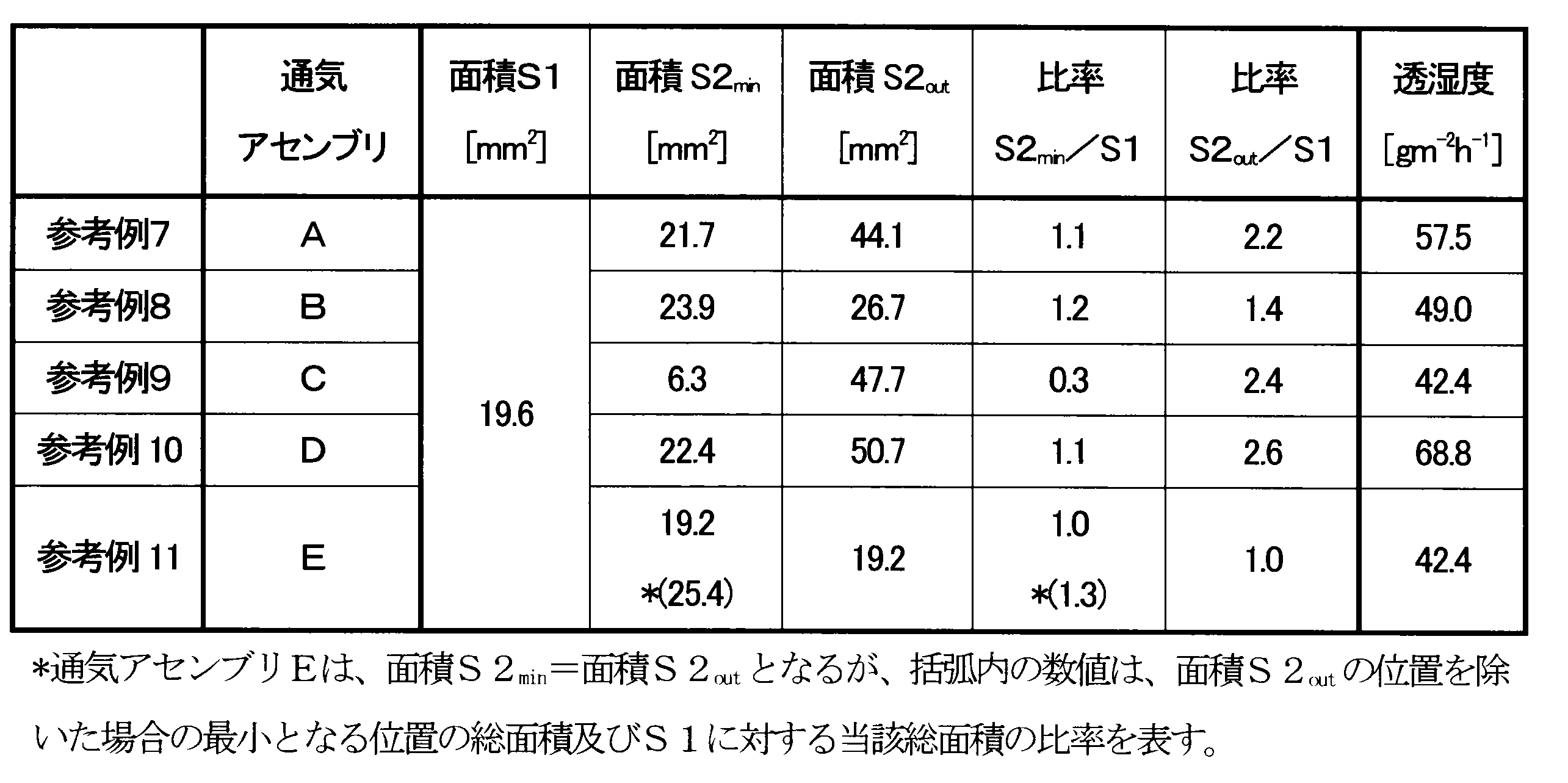
(参考例12)
オレフィン系熱可塑エラストマー(三井化学株式会社製ミラストマー(登録商標)、硬度71、密度880kg/m3)を材料として用いて、図26Aの形状の内部部材2を射出成型により作製した。得られた内部部材2における突出部21を有する部分の厚みは4.2mm、突出部21を有さない部分(非突出部)の厚みは2.3mm、突出部21を有する部分の外径は16mm、非突出部の外径は12mm、内径は7.5mm、高さH1は6.0mmであった。
内部部材2の高さH1及び突起52の高さH2を表3に記載の値に変更した以外は、参考例12と同様の方法により、引張試験(内部部材の引抜試験)を実施した。引抜力の結果を表3に示す。
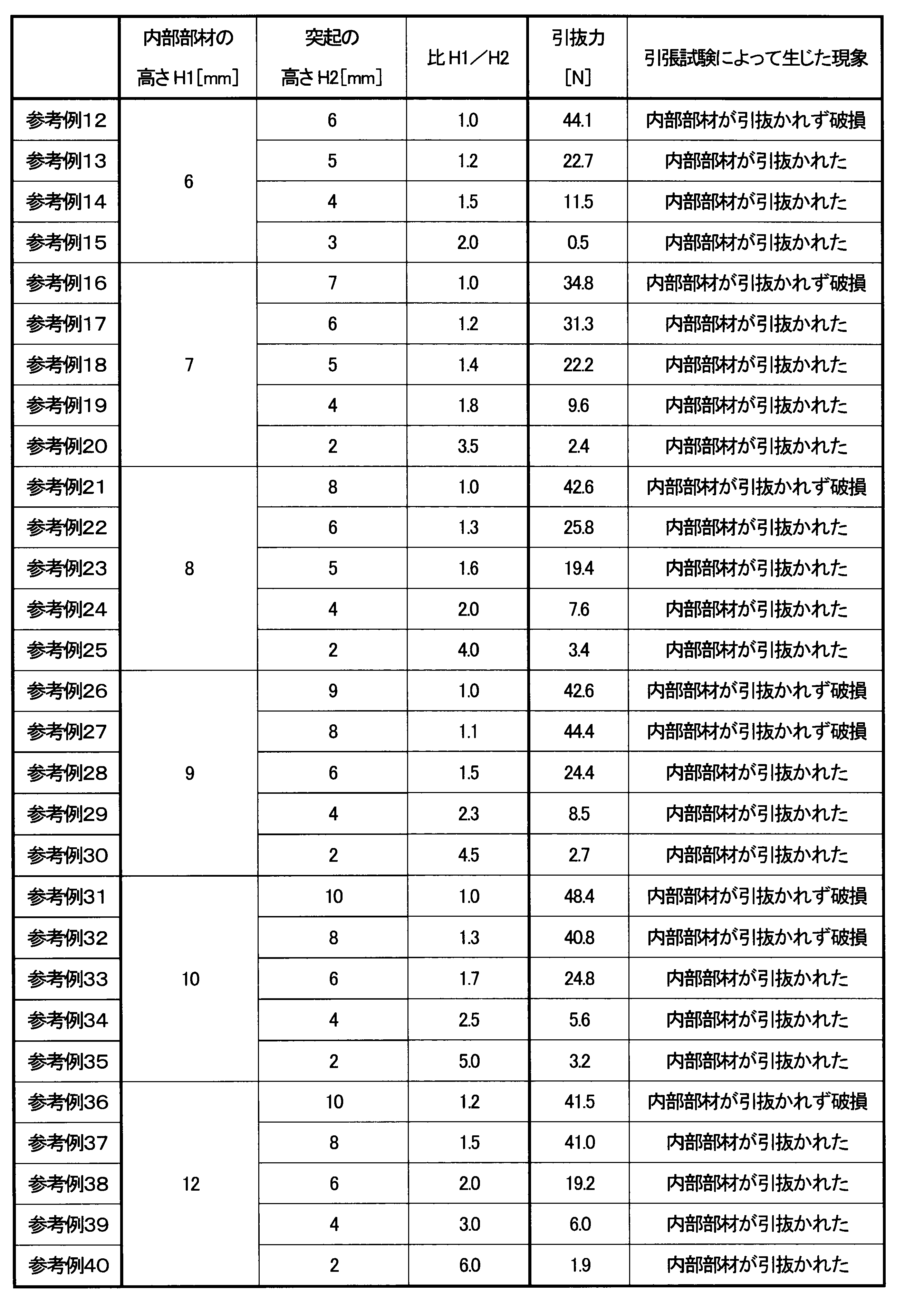
(参考例41)
オレフィン系熱可塑エラストマー(三井化学株式会社製ミラストマー(登録商標)、硬度71、密度880kg/m3)を材料として用いて、図26Aの形状の内部部材2を射出成型により作製した。得られた内部部材2における突出部21を有する部分の厚みは4.2mm、突出部21を有さない部分(非突出部)の厚みは2.3mm、突出部21を有する部分の外径は16mm、非突出部の外径は12mm、内径は7.5mm、高さH1は6.0mmであった。
突起の外径、外部部材の高さ、及び外部部材の挿入深さを表4に記載の値に変更した以外は、参考例41と同様の方法により、引張試験(外部部材の引抜試験)を実施した。引抜力の結果を表4に示す。表4の「外部部材の挿入深さ」と「内外接触長さ」は、<通気アセンブリ及び通気筐体の透湿試験1>において説明したとおりである。
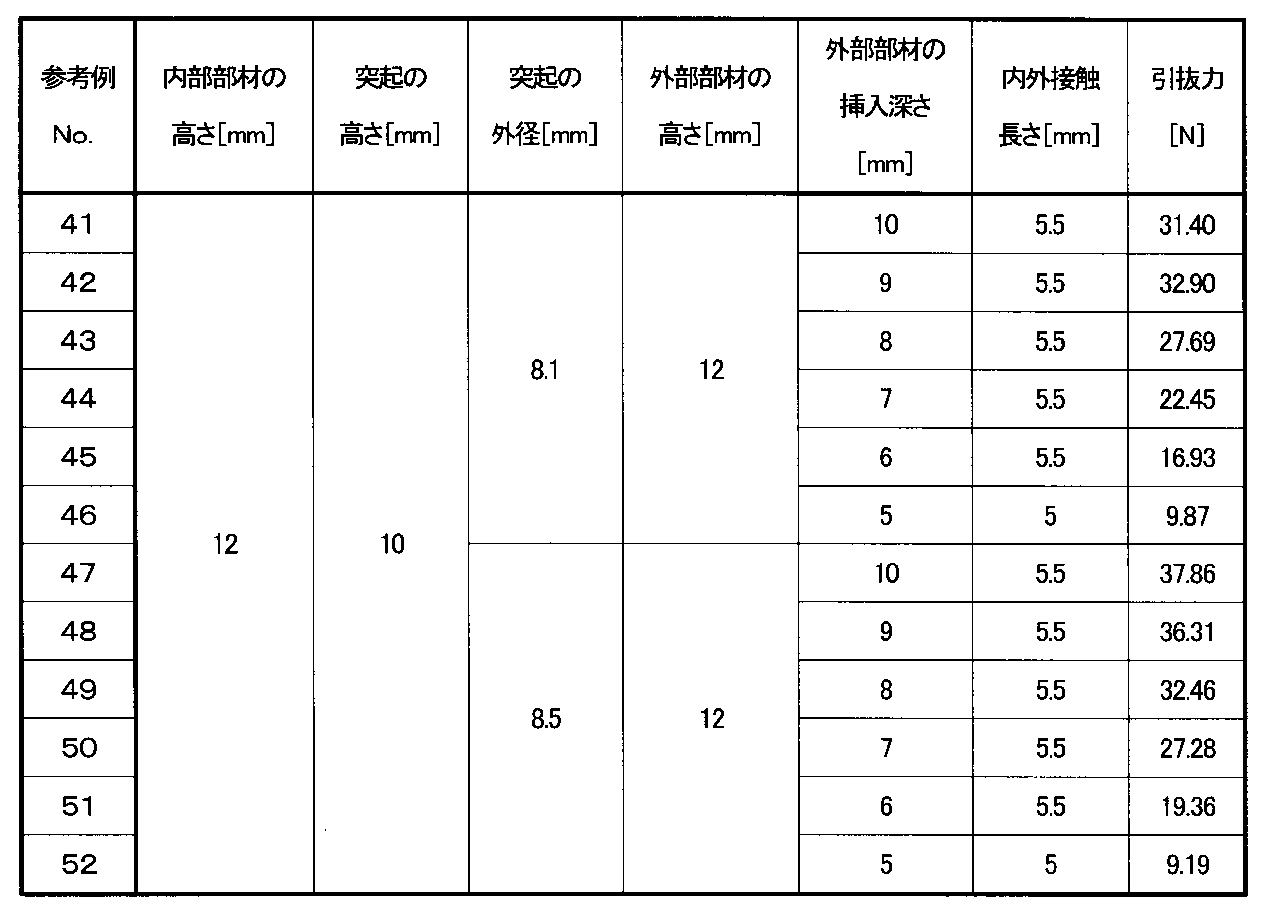
Claims (9)
- 筐体の外表面から突出して延びるとともに前記筐体の内外を連通する第1の空間を内側に有する筒状の突起に固定される通気アセンブリであって、
双方の端部に開口を有する筒状体である内部部材と、有底の筒状体である外部部材と、前記内部部材の一方の前記端部における前記開口を覆う通気膜と、を備え、
前記外部部材は、前記外部部材の内側に前記内部部材が前記一方の端部の側から挿入された状態で、前記内部部材と接合され、
前記内部部材の内部、前記外部部材の内部、及び接合した前記内部部材と前記外部部材との間から選ばれる少なくとも1つに、前記通気膜と前記通気アセンブリの外部とを接続する通気路となる第2の空間を有し、
前記内部部材は、前記通気膜に対して前記他方の端部側の位置に、前記内周面から突出した1又は2以上の第1の突起部を備えたことを特徴とする、通気アセンブリ。 - 前記内部部材は、2以上の前記第1の突起部を備え、
前記2以上の第1の突起部が、前記内部部材の内部の空間で互いに接合されている、請求項1に記載の通気アセンブリ。 - 前記第1の突起部と前記通気膜とが離間している、請求項1又は2に記載の通気アセンブリ。
- 前記内部部材の高さが6.0mm以上10mm以下である、請求項1~3のいずれかに記載の通気アセンブリ。
- 前記通気アセンブリの中心軸に垂直な方向に観察したときに、
前記内部部材における前記外部部材により覆われる部分の前記中心軸に沿う方向の長さが6.0mm以上8.0mm以下である、請求項1~4のいずれかに記載の通気アセンブリ。 - 前記外部部材及び/又は前記内部部材が、前記外部部材と前記内部部材とを脱着可能に接合する係止機構を有する、請求項1~5のいずれかに記載の通気アセンブリ。
- 筐体と通気アセンブリとを備える通気筐体であって、
前記筐体は、前記筐体の外表面から突出して延びるとともに前記筐体の内外を連通する第1の空間を内側に有する筒状の突起を備え、
前記通気アセンブリは、請求項1~6のいずれかに記載の通気アセンブリであり、
前記内部部材の他方の前記端部における前記開口から前記突起を前記内部部材に挿入して、前記内部部材の内周面と前記突起の外周面とが当接した状態で、前記通気アセンブリが前記突起に固定されており、
前記通気アセンブリの前記1又は2以上の第1の突起部は、前記突起の先端と前記通気膜との間に位置している、通気筐体。 - 前記突起の中心軸に垂直な平面により切断した前記第1の空間の断面の面積S1と、前記通気路としての通気方向に垂直な平面により切断した前記第2の空間の断面の面積を前記通気膜からの距離毎に合計した総面積が最小となる位置の総面積S2minとの比率S2min/S1が1.0以上である、請求項7に記載の通気筐体。
- 前記突起の中心軸に垂直な平面により切断した前記第1の空間の断面の面積S1と、前記通気アセンブリの中心軸に沿って前記他方の端部側から前記第2の空間を観察したときに、前記第2の空間が最も狭くなる位置の断面を表す平面の総面積S2outとの比率S2out/S1が1.0以上である、請求項7又は8に記載の通気筐体。
Priority Applications (7)
| Application Number | Priority Date | Filing Date | Title |
|---|---|---|---|
| JP2020551250A JP7389046B2 (ja) | 2018-10-11 | 2019-10-11 | 通気アセンブリ及び通気筐体 |
| DE112019005103.2T DE112019005103T5 (de) | 2018-10-11 | 2019-10-11 | Belüftungsanordnung und Belüftungsgehäuse |
| MX2021004086A MX2021004086A (es) | 2018-10-11 | 2019-10-11 | Montaje de ventilacion y alojamiento de ventilacion. |
| KR1020217013648A KR102636995B1 (ko) | 2018-10-11 | 2019-10-11 | 통기 어셈블리 및 통기 하우징 |
| BR112021006494A BR112021006494A2 (pt) | 2018-10-11 | 2019-10-11 | conjunto de ventilação e revestimento de ventilação |
| CN201980003084.5A CN111316763B (zh) | 2018-10-11 | 2019-10-11 | 通气组件及通气壳体 |
| US17/282,669 US11963317B2 (en) | 2018-10-11 | 2019-10-11 | Ventilation assembly and ventilation housing |
Applications Claiming Priority (2)
| Application Number | Priority Date | Filing Date | Title |
|---|---|---|---|
| JP2018-192350 | 2018-10-11 | ||
| JP2018192350 | 2018-10-11 |
Publications (1)
| Publication Number | Publication Date |
|---|---|
| WO2020075855A1 true WO2020075855A1 (ja) | 2020-04-16 |
Family
ID=70163706
Family Applications (1)
| Application Number | Title | Priority Date | Filing Date |
|---|---|---|---|
| PCT/JP2019/040314 Ceased WO2020075855A1 (ja) | 2018-10-11 | 2019-10-11 | 通気アセンブリ及び通気筐体 |
Country Status (8)
| Country | Link |
|---|---|
| US (1) | US11963317B2 (ja) |
| JP (1) | JP7389046B2 (ja) |
| KR (1) | KR102636995B1 (ja) |
| CN (1) | CN111316763B (ja) |
| BR (1) | BR112021006494A2 (ja) |
| DE (1) | DE112019005103T5 (ja) |
| MX (1) | MX2021004086A (ja) |
| WO (1) | WO2020075855A1 (ja) |
Cited By (1)
| Publication number | Priority date | Publication date | Assignee | Title |
|---|---|---|---|---|
| KR20210151695A (ko) * | 2020-06-05 | 2021-12-14 | 더블유.엘. 고어 앤드 어소시에이트스, 인코포레이티드 | 개선된 기하학 및 누수 압력을 갖는 접착성 막을 포함하는 물품 |
Families Citing this family (4)
| Publication number | Priority date | Publication date | Assignee | Title |
|---|---|---|---|---|
| JP7489320B2 (ja) * | 2018-10-11 | 2024-05-23 | 日東電工株式会社 | 通気筐体 |
| US12342480B2 (en) * | 2018-10-11 | 2025-06-24 | Nitto Denko Corporation | Ventilation assembly and ventilation housing |
| TWI765624B (zh) * | 2021-03-26 | 2022-05-21 | 啓碁科技股份有限公司 | 電子裝置及其鎖附固定結構 |
| CN115199988A (zh) * | 2022-09-16 | 2022-10-18 | 常州通宝光电股份有限公司 | 一种基于红外探测技术的车灯组件及照明装置 |
Citations (5)
| Publication number | Priority date | Publication date | Assignee | Title |
|---|---|---|---|---|
| JP2001143524A (ja) * | 1999-11-18 | 2001-05-25 | Nitto Denko Corp | 通気キャップおよびそれを用いた屋外用ランプ,自動車用ランプならびに自動車用電装部品 |
| JP2005349362A (ja) * | 2004-06-14 | 2005-12-22 | Nitto Denko Corp | 通気部材の製造方法およびそれによって得られる通気部材ならびにそれを用いた筐体。 |
| JP2007087929A (ja) * | 2005-08-24 | 2007-04-05 | Nitto Denko Corp | 通気部材 |
| JP2011023206A (ja) * | 2009-07-15 | 2011-02-03 | Japan Gore Tex Inc | 通気栓 |
| JP2013114829A (ja) * | 2011-11-28 | 2013-06-10 | Nitto Denko Corp | 通気部材 |
Family Cites Families (23)
| Publication number | Priority date | Publication date | Assignee | Title |
|---|---|---|---|---|
| KR200280975Y1 (ko) * | 2002-03-27 | 2002-07-13 | 정인석 | 에어밴트 |
| JP2003336874A (ja) | 2002-05-15 | 2003-11-28 | Nitto Denko Corp | 通気部材およびこれを用いた通気筐体 |
| US7833647B2 (en) | 2004-04-28 | 2010-11-16 | Eveready Battery Company, Inc. | Closure vent seal and assembly |
| JP4517227B2 (ja) | 2004-07-13 | 2010-08-04 | 有限会社中島工業 | 自動車用ヘッドライト内圧調整用フィルタ |
| DE602005015489D1 (de) | 2004-12-07 | 2009-08-27 | Nitto Denko Corp | Durchlässiges glied, das durchlässige glied verwendendes durchlässiges gehäuse und elektrisches teil |
| CN100587332C (zh) * | 2005-08-24 | 2010-02-03 | 日东电工株式会社 | 透气构件 |
| JP4855203B2 (ja) | 2005-12-14 | 2012-01-18 | 日東電工株式会社 | 通気部材および通気構造 |
| US20100227544A1 (en) | 2005-12-14 | 2010-09-09 | Nitto Denko Corporation | Vent Member and Vent Structure |
| JP5508044B2 (ja) | 2010-01-22 | 2014-05-28 | 大成プラス株式会社 | 通気キャップとその製造方法 |
| JP5714403B2 (ja) | 2011-04-27 | 2015-05-07 | 日東電工株式会社 | 通気ユニット |
| KR101555402B1 (ko) * | 2011-10-19 | 2015-09-24 | 현대모비스 주식회사 | 다공질 기능성 막. |
| CN203036605U (zh) | 2012-11-01 | 2013-07-03 | 日东电工株式会社 | 透气构件 |
| JP2015033682A (ja) | 2013-08-09 | 2015-02-19 | 日東電工株式会社 | 通気構造及び通気部材 |
| KR20170013888A (ko) | 2014-05-28 | 2017-02-07 | 닛토덴코 가부시키가이샤 | 금속 하우징 및 그것을 사용한 통기 구조 |
| ES2799927T3 (es) | 2015-02-18 | 2020-12-22 | Gvs Spa | Elemento para ventilación mejorada de un alojamiento que contiene un dispositivo eléctrico, electrónico, mecánico o similar |
| JP6721978B2 (ja) | 2015-12-15 | 2020-07-15 | 日東電工株式会社 | 通気部材、ランプ |
| KR102515289B1 (ko) * | 2016-01-08 | 2023-03-29 | 엘지이노텍 주식회사 | 전자 디바이스용 마개 |
| WO2018021514A1 (ja) | 2016-07-29 | 2018-02-01 | 株式会社村田製作所 | バルブ、気体制御装置 |
| KR101701469B1 (ko) * | 2016-09-09 | 2017-02-03 | (주)상아프론테크 | 자동차용 통기 캡 |
| KR102021145B1 (ko) | 2017-01-25 | 2019-09-11 | 주식회사 아모그린텍 | 캡 타입 벤트 |
| WO2020075858A1 (ja) * | 2018-10-11 | 2020-04-16 | 日東電工株式会社 | 通気筐体 |
| US12342480B2 (en) | 2018-10-11 | 2025-06-24 | Nitto Denko Corporation | Ventilation assembly and ventilation housing |
| JP7489320B2 (ja) | 2018-10-11 | 2024-05-23 | 日東電工株式会社 | 通気筐体 |
-
2019
- 2019-10-11 KR KR1020217013648A patent/KR102636995B1/ko active Active
- 2019-10-11 MX MX2021004086A patent/MX2021004086A/es unknown
- 2019-10-11 BR BR112021006494A patent/BR112021006494A2/pt not_active Application Discontinuation
- 2019-10-11 JP JP2020551250A patent/JP7389046B2/ja active Active
- 2019-10-11 DE DE112019005103.2T patent/DE112019005103T5/de active Pending
- 2019-10-11 CN CN201980003084.5A patent/CN111316763B/zh active Active
- 2019-10-11 WO PCT/JP2019/040314 patent/WO2020075855A1/ja not_active Ceased
- 2019-10-11 US US17/282,669 patent/US11963317B2/en active Active
Patent Citations (5)
| Publication number | Priority date | Publication date | Assignee | Title |
|---|---|---|---|---|
| JP2001143524A (ja) * | 1999-11-18 | 2001-05-25 | Nitto Denko Corp | 通気キャップおよびそれを用いた屋外用ランプ,自動車用ランプならびに自動車用電装部品 |
| JP2005349362A (ja) * | 2004-06-14 | 2005-12-22 | Nitto Denko Corp | 通気部材の製造方法およびそれによって得られる通気部材ならびにそれを用いた筐体。 |
| JP2007087929A (ja) * | 2005-08-24 | 2007-04-05 | Nitto Denko Corp | 通気部材 |
| JP2011023206A (ja) * | 2009-07-15 | 2011-02-03 | Japan Gore Tex Inc | 通気栓 |
| JP2013114829A (ja) * | 2011-11-28 | 2013-06-10 | Nitto Denko Corp | 通気部材 |
Cited By (5)
| Publication number | Priority date | Publication date | Assignee | Title |
|---|---|---|---|---|
| KR20210151695A (ko) * | 2020-06-05 | 2021-12-14 | 더블유.엘. 고어 앤드 어소시에이트스, 인코포레이티드 | 개선된 기하학 및 누수 압력을 갖는 접착성 막을 포함하는 물품 |
| JP2021192976A (ja) * | 2020-06-05 | 2021-12-23 | ダブリュ.エル.ゴア アンド アソシエイツ, インコーポレイティドW.L. Gore & Associates, Incorporated | 改良された幾何形状及び水侵入圧力を備えた接着膜を含む物品 |
| JP7177888B2 (ja) | 2020-06-05 | 2022-11-24 | ダブリュ.エル.ゴア アンド アソシエイツ,インコーポレイティド | 改良された幾何形状及び水侵入圧力を備えた接着膜を含む物品 |
| KR102530205B1 (ko) | 2020-06-05 | 2023-05-08 | 더블유.엘. 고어 앤드 어소시에이트스, 인코포레이티드 | 개선된 기하학 및 누수 압력을 갖는 접착성 막을 포함하는 물품 |
| US12246288B2 (en) | 2020-06-05 | 2025-03-11 | W. L. Gore & Associates, Inc. | Articles comprising adhesive membranes with improved geometry and water entry pressure |
Also Published As
| Publication number | Publication date |
|---|---|
| JP7389046B2 (ja) | 2023-11-29 |
| MX2021004086A (es) | 2021-06-04 |
| US11963317B2 (en) | 2024-04-16 |
| CN111316763A (zh) | 2020-06-19 |
| KR102636995B1 (ko) | 2024-02-16 |
| KR20210068556A (ko) | 2021-06-09 |
| JPWO2020075855A1 (ja) | 2021-09-09 |
| DE112019005103T5 (de) | 2021-07-08 |
| US20220201878A1 (en) | 2022-06-23 |
| CN111316763B (zh) | 2023-03-07 |
| BR112021006494A2 (pt) | 2021-07-06 |
Similar Documents
| Publication | Publication Date | Title |
|---|---|---|
| WO2020075855A1 (ja) | 通気アセンブリ及び通気筐体 | |
| WO2020075856A1 (ja) | 通気アセンブリ及び通気筐体 | |
| JP2024042044A (ja) | 通気筐体 | |
| JP2024042043A (ja) | 通気筐体 | |
| JP7187444B2 (ja) | 通気部材 | |
| KR20130041805A (ko) | 통기 부재 | |
| WO2020075848A1 (ja) | 通気筐体 |
Legal Events
| Date | Code | Title | Description |
|---|---|---|---|
| 121 | Ep: the epo has been informed by wipo that ep was designated in this application |
Ref document number: 19871118 Country of ref document: EP Kind code of ref document: A1 |
|
| ENP | Entry into the national phase |
Ref document number: 2020551250 Country of ref document: JP Kind code of ref document: A |
|
| REG | Reference to national code |
Ref country code: BR Ref legal event code: B01A Ref document number: 112021006494 Country of ref document: BR |
|
| ENP | Entry into the national phase |
Ref document number: 20217013648 Country of ref document: KR Kind code of ref document: A |
|
| ENP | Entry into the national phase |
Ref document number: 112021006494 Country of ref document: BR Kind code of ref document: A2 Effective date: 20210405 |
|
| 122 | Ep: pct application non-entry in european phase |
Ref document number: 19871118 Country of ref document: EP Kind code of ref document: A1 |