WO2020071345A1 - 車両制御装置および車両制御システム - Google Patents
車両制御装置および車両制御システムInfo
- Publication number
- WO2020071345A1 WO2020071345A1 PCT/JP2019/038688 JP2019038688W WO2020071345A1 WO 2020071345 A1 WO2020071345 A1 WO 2020071345A1 JP 2019038688 W JP2019038688 W JP 2019038688W WO 2020071345 A1 WO2020071345 A1 WO 2020071345A1
- Authority
- WO
- WIPO (PCT)
- Prior art keywords
- unit
- vehicle control
- control device
- signal processing
- braking
- Prior art date
- Legal status (The legal status is an assumption and is not a legal conclusion. Google has not performed a legal analysis and makes no representation as to the accuracy of the status listed.)
- Ceased
Links
Images



Classifications
-
- B—PERFORMING OPERATIONS; TRANSPORTING
- B60—VEHICLES IN GENERAL
- B60T—VEHICLE BRAKE CONTROL SYSTEMS OR PARTS THEREOF; BRAKE CONTROL SYSTEMS OR PARTS THEREOF, IN GENERAL; ARRANGEMENT OF BRAKING ELEMENTS ON VEHICLES IN GENERAL; PORTABLE DEVICES FOR PREVENTING UNWANTED MOVEMENT OF VEHICLES; VEHICLE MODIFICATIONS TO FACILITATE COOLING OF BRAKES
- B60T1/00—Arrangements of braking elements, i.e. of those parts where braking effect occurs specially for vehicles
- B60T1/02—Arrangements of braking elements, i.e. of those parts where braking effect occurs specially for vehicles acting by retarding wheels
- B60T1/10—Arrangements of braking elements, i.e. of those parts where braking effect occurs specially for vehicles acting by retarding wheels by utilising wheel movement for accumulating energy, e.g. driving air compressors
-
- B—PERFORMING OPERATIONS; TRANSPORTING
- B60—VEHICLES IN GENERAL
- B60T—VEHICLE BRAKE CONTROL SYSTEMS OR PARTS THEREOF; BRAKE CONTROL SYSTEMS OR PARTS THEREOF, IN GENERAL; ARRANGEMENT OF BRAKING ELEMENTS ON VEHICLES IN GENERAL; PORTABLE DEVICES FOR PREVENTING UNWANTED MOVEMENT OF VEHICLES; VEHICLE MODIFICATIONS TO FACILITATE COOLING OF BRAKES
- B60T8/00—Arrangements for adjusting wheel-braking force to meet varying vehicular or ground-surface conditions, e.g. limiting or varying distribution of braking force
- B60T8/32—Arrangements for adjusting wheel-braking force to meet varying vehicular or ground-surface conditions, e.g. limiting or varying distribution of braking force responsive to a speed condition, e.g. acceleration or deceleration
- B60T8/321—Arrangements for adjusting wheel-braking force to meet varying vehicular or ground-surface conditions, e.g. limiting or varying distribution of braking force responsive to a speed condition, e.g. acceleration or deceleration deceleration
- B60T8/329—Systems characterised by their speed sensor arrangements
-
- B—PERFORMING OPERATIONS; TRANSPORTING
- B60—VEHICLES IN GENERAL
- B60T—VEHICLE BRAKE CONTROL SYSTEMS OR PARTS THEREOF; BRAKE CONTROL SYSTEMS OR PARTS THEREOF, IN GENERAL; ARRANGEMENT OF BRAKING ELEMENTS ON VEHICLES IN GENERAL; PORTABLE DEVICES FOR PREVENTING UNWANTED MOVEMENT OF VEHICLES; VEHICLE MODIFICATIONS TO FACILITATE COOLING OF BRAKES
- B60T13/00—Transmitting braking action from initiating means to ultimate brake actuator with power assistance or drive; Brake systems incorporating such transmitting means, e.g. air-pressure brake systems
- B60T13/10—Transmitting braking action from initiating means to ultimate brake actuator with power assistance or drive; Brake systems incorporating such transmitting means, e.g. air-pressure brake systems with fluid assistance, drive, or release
- B60T13/58—Combined or convertible systems
- B60T13/588—Combined or convertible systems both fluid and mechanical assistance or drive
-
- B—PERFORMING OPERATIONS; TRANSPORTING
- B60—VEHICLES IN GENERAL
- B60T—VEHICLE BRAKE CONTROL SYSTEMS OR PARTS THEREOF; BRAKE CONTROL SYSTEMS OR PARTS THEREOF, IN GENERAL; ARRANGEMENT OF BRAKING ELEMENTS ON VEHICLES IN GENERAL; PORTABLE DEVICES FOR PREVENTING UNWANTED MOVEMENT OF VEHICLES; VEHICLE MODIFICATIONS TO FACILITATE COOLING OF BRAKES
- B60T17/00—Component parts, details, or accessories of power brake systems not covered by groups B60T8/00, B60T13/00 or B60T15/00, or presenting other characteristic features
- B60T17/18—Safety devices; Monitoring
- B60T17/22—Devices for monitoring or checking brake systems; Signal devices
-
- B—PERFORMING OPERATIONS; TRANSPORTING
- B60—VEHICLES IN GENERAL
- B60T—VEHICLE BRAKE CONTROL SYSTEMS OR PARTS THEREOF; BRAKE CONTROL SYSTEMS OR PARTS THEREOF, IN GENERAL; ARRANGEMENT OF BRAKING ELEMENTS ON VEHICLES IN GENERAL; PORTABLE DEVICES FOR PREVENTING UNWANTED MOVEMENT OF VEHICLES; VEHICLE MODIFICATIONS TO FACILITATE COOLING OF BRAKES
- B60T8/00—Arrangements for adjusting wheel-braking force to meet varying vehicular or ground-surface conditions, e.g. limiting or varying distribution of braking force
- B60T8/17—Using electrical or electronic regulation means to control braking
- B60T8/171—Detecting parameters used in the regulation; Measuring values used in the regulation
-
- B—PERFORMING OPERATIONS; TRANSPORTING
- B60—VEHICLES IN GENERAL
- B60T—VEHICLE BRAKE CONTROL SYSTEMS OR PARTS THEREOF; BRAKE CONTROL SYSTEMS OR PARTS THEREOF, IN GENERAL; ARRANGEMENT OF BRAKING ELEMENTS ON VEHICLES IN GENERAL; PORTABLE DEVICES FOR PREVENTING UNWANTED MOVEMENT OF VEHICLES; VEHICLE MODIFICATIONS TO FACILITATE COOLING OF BRAKES
- B60T8/00—Arrangements for adjusting wheel-braking force to meet varying vehicular or ground-surface conditions, e.g. limiting or varying distribution of braking force
- B60T8/17—Using electrical or electronic regulation means to control braking
- B60T8/172—Determining control parameters used in the regulation, e.g. by calculations involving measured or detected parameters
-
- B—PERFORMING OPERATIONS; TRANSPORTING
- B60—VEHICLES IN GENERAL
- B60T—VEHICLE BRAKE CONTROL SYSTEMS OR PARTS THEREOF; BRAKE CONTROL SYSTEMS OR PARTS THEREOF, IN GENERAL; ARRANGEMENT OF BRAKING ELEMENTS ON VEHICLES IN GENERAL; PORTABLE DEVICES FOR PREVENTING UNWANTED MOVEMENT OF VEHICLES; VEHICLE MODIFICATIONS TO FACILITATE COOLING OF BRAKES
- B60T8/00—Arrangements for adjusting wheel-braking force to meet varying vehicular or ground-surface conditions, e.g. limiting or varying distribution of braking force
- B60T8/32—Arrangements for adjusting wheel-braking force to meet varying vehicular or ground-surface conditions, e.g. limiting or varying distribution of braking force responsive to a speed condition, e.g. acceleration or deceleration
- B60T8/88—Arrangements for adjusting wheel-braking force to meet varying vehicular or ground-surface conditions, e.g. limiting or varying distribution of braking force responsive to a speed condition, e.g. acceleration or deceleration with failure responsive means, i.e. means for detecting and indicating faulty operation of the speed responsive control means
- B60T8/92—Arrangements for adjusting wheel-braking force to meet varying vehicular or ground-surface conditions, e.g. limiting or varying distribution of braking force responsive to a speed condition, e.g. acceleration or deceleration with failure responsive means, i.e. means for detecting and indicating faulty operation of the speed responsive control means automatically taking corrective action
- B60T8/94—Arrangements for adjusting wheel-braking force to meet varying vehicular or ground-surface conditions, e.g. limiting or varying distribution of braking force responsive to a speed condition, e.g. acceleration or deceleration with failure responsive means, i.e. means for detecting and indicating faulty operation of the speed responsive control means automatically taking corrective action on a fluid pressure regulator
-
- B—PERFORMING OPERATIONS; TRANSPORTING
- B60—VEHICLES IN GENERAL
- B60T—VEHICLE BRAKE CONTROL SYSTEMS OR PARTS THEREOF; BRAKE CONTROL SYSTEMS OR PARTS THEREOF, IN GENERAL; ARRANGEMENT OF BRAKING ELEMENTS ON VEHICLES IN GENERAL; PORTABLE DEVICES FOR PREVENTING UNWANTED MOVEMENT OF VEHICLES; VEHICLE MODIFICATIONS TO FACILITATE COOLING OF BRAKES
- B60T8/00—Arrangements for adjusting wheel-braking force to meet varying vehicular or ground-surface conditions, e.g. limiting or varying distribution of braking force
- B60T8/32—Arrangements for adjusting wheel-braking force to meet varying vehicular or ground-surface conditions, e.g. limiting or varying distribution of braking force responsive to a speed condition, e.g. acceleration or deceleration
- B60T8/88—Arrangements for adjusting wheel-braking force to meet varying vehicular or ground-surface conditions, e.g. limiting or varying distribution of braking force responsive to a speed condition, e.g. acceleration or deceleration with failure responsive means, i.e. means for detecting and indicating faulty operation of the speed responsive control means
- B60T8/92—Arrangements for adjusting wheel-braking force to meet varying vehicular or ground-surface conditions, e.g. limiting or varying distribution of braking force responsive to a speed condition, e.g. acceleration or deceleration with failure responsive means, i.e. means for detecting and indicating faulty operation of the speed responsive control means automatically taking corrective action
- B60T8/96—Arrangements for adjusting wheel-braking force to meet varying vehicular or ground-surface conditions, e.g. limiting or varying distribution of braking force responsive to a speed condition, e.g. acceleration or deceleration with failure responsive means, i.e. means for detecting and indicating faulty operation of the speed responsive control means automatically taking corrective action on speed responsive control means
-
- F—MECHANICAL ENGINEERING; LIGHTING; HEATING; WEAPONS; BLASTING
- F16—ENGINEERING ELEMENTS AND UNITS; GENERAL MEASURES FOR PRODUCING AND MAINTAINING EFFECTIVE FUNCTIONING OF MACHINES OR INSTALLATIONS; THERMAL INSULATION IN GENERAL
- F16D—COUPLINGS FOR TRANSMITTING ROTATION; CLUTCHES; BRAKES
- F16D61/00—Brakes with means for making the energy absorbed available for use
-
- B—PERFORMING OPERATIONS; TRANSPORTING
- B60—VEHICLES IN GENERAL
- B60T—VEHICLE BRAKE CONTROL SYSTEMS OR PARTS THEREOF; BRAKE CONTROL SYSTEMS OR PARTS THEREOF, IN GENERAL; ARRANGEMENT OF BRAKING ELEMENTS ON VEHICLES IN GENERAL; PORTABLE DEVICES FOR PREVENTING UNWANTED MOVEMENT OF VEHICLES; VEHICLE MODIFICATIONS TO FACILITATE COOLING OF BRAKES
- B60T2270/00—Further aspects of brake control systems not otherwise provided for
- B60T2270/40—Failsafe aspects of brake control systems
- B60T2270/413—Plausibility monitoring, cross check, redundancy
-
- B—PERFORMING OPERATIONS; TRANSPORTING
- B60—VEHICLES IN GENERAL
- B60T—VEHICLE BRAKE CONTROL SYSTEMS OR PARTS THEREOF; BRAKE CONTROL SYSTEMS OR PARTS THEREOF, IN GENERAL; ARRANGEMENT OF BRAKING ELEMENTS ON VEHICLES IN GENERAL; PORTABLE DEVICES FOR PREVENTING UNWANTED MOVEMENT OF VEHICLES; VEHICLE MODIFICATIONS TO FACILITATE COOLING OF BRAKES
- B60T2270/00—Further aspects of brake control systems not otherwise provided for
- B60T2270/60—Regenerative braking
- B60T2270/604—Merging friction therewith; Adjusting their repartition
Definitions
- the present invention relates to a vehicle control device and a vehicle control system.
- Patent Literature 1 discloses a vehicle in which two wheel speed sensors are installed for one wheel, a first brake control device connected to the first wheel speed sensor via wiring, and a second wheel A vehicle control device including a speed sensor and a second brake control device connected via wiring is disclosed.
- An object of the present invention is to provide a vehicle control device and a vehicle control system that can suppress a deterioration in layout and an increase in cost when making redundant wheel speed detection.
- the first braking command unit and the second braking command unit are electrically connected to the same wheel speed sensor.
- FIG. 1 is a configuration diagram of a vehicle control system A according to a first embodiment.
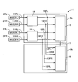
- 1 is a configuration diagram of a vehicle control device 1 according to a first embodiment.
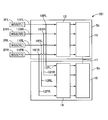
- FIG. 5 is a configuration diagram of a vehicle control device 100 according to a second embodiment.
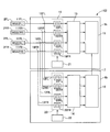
- FIG. 9 is a configuration diagram of a vehicle control device 101 according to a third embodiment.
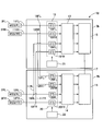
- FIG. 9 is a configuration diagram of a vehicle control device 102 according to a fourth embodiment.
- FIG. 14 is a configuration diagram of a vehicle control device 103 according to a fifth embodiment.
- FIG. 13 is a configuration diagram of a vehicle control device 104 according to a sixth embodiment.
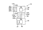
- FIG. 14 is a configuration diagram of a main part of a vehicle control system B according to a seventh embodiment.
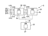
- FIG. 19 is a configuration diagram of a main part of a vehicle control system C according to an eighth embodiment.
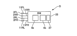
- FIG. 19 is a configuration diagram of a main part of a vehicle control system D according to a ninth embodiment.
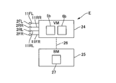
- FIG. 21 is a main part configuration diagram of a vehicle control system E according to a tenth embodiment.
- FIG. 1 is a configuration diagram of the vehicle control system A of the first embodiment.
- the vehicle control system A is, for example, a brake control system mounted on an electric vehicle.
- the vehicle control system A includes a wheel speed sensor 2, a wheel cylinder (braking force applying unit) 3, a master cylinder 4, a first brake module (first braking function unit) 5, and a second brake module (second braking unit). Function unit) 6.
- the suffix P of the code indicates that it corresponds to the primary system (P system) of the master cylinder 4.
- the suffix S of the code indicates that it corresponds to the secondary system (S system) of the master cylinder 4.
- the description of P and S is omitted.
- the end FL of the code indicates that it corresponds to the left front wheel FL.
- the end FR of the code indicates that it corresponds to the right front wheel FR.
- the end RL of the code indicates that it corresponds to the left rear wheel RL.
- the end RR of the code indicates that it corresponds to the right rear wheel RR. If the wheels FL to RR are not distinguished, the description of FL, FR, RL, RR is omitted.
- the wheel speed sensor 2 is provided for each wheel, detects a rotation speed (wheel speed) of the wheel, and outputs an electric signal (for example, a sine wave or rectangular wave pulse signal for changing current or voltage, a SENT signal) corresponding to the wheel speed.
- an electric signal for example, a sine wave or rectangular wave pulse signal for changing current or voltage, a SENT signal
- communication signals based on an IC communication protocol such as SPI and SPI
- communication signals based on a vehicle-mounted device communication protocol such as CAN and Flex Ray.
- a wheel speed sensor that outputs a pulse signal a sensor generally adopted at present can be used.
- a wheel speed sensor that outputs a communication signal in accordance with the inter-IC communication protocol or the in-vehicle device communication protocol, it is possible to suppress the influence of noise generated on the transmission path (wiring).
- the wheel cylinder 3 presses a brake pad provided on the vehicle body side corresponding to the wheel against a brake disc provided on the wheel side to control the wheel. Give power.
- the master cylinder 4 operates according to the operation of the brake pedal 7 (brake operation) by the driver, and generates a brake fluid pressure (master cylinder fluid pressure).
- the first brake module 5 and the second brake module 6 are provided between the master cylinder 4 and the wheel cylinder 3.
- the first brake module 5 is a first hydraulic unit (a first braking force control unit) 5a and a first electronic control unit (a first braking command unit and a first control unit.
- One ECU) 5b One ECU
- the first hydraulic unit 5a has a plurality of actuators (motor pumps, a plurality of solenoid valves), and can apply brake fluid to the wheel cylinder 3 independently of a driver's braking operation.
- the first ECU 5b controls the operation of the first hydraulic unit 5a.
- the second brake module 6 is a second hydraulic unit (second braking force control unit) 6a and a second electronic control unit (second braking command unit and second control unit. 2 ECUs) 6b.
- the second hydraulic unit 6a has a plurality of actuators (motor pumps, a plurality of solenoid valves), and can apply brake fluid to the wheel cylinders 3 independently of a driver's braking operation.
- the second ECU 6b controls the operation of the second hydraulic unit 6a.
- the master cylinder 4 and the second hydraulic unit 6a are connected by a first primary pipe 8P and a first secondary pipe 8S.
- the first primary pipe 8P is connected to the primary hydraulic chamber of the master cylinder 4.
- the first secondary pipe 8S is connected to the secondary hydraulic chamber of the master cylinder 4.
- the second hydraulic unit 6a and the first hydraulic unit 5a are connected by a second primary pipe 9P and a second secondary pipe 9S.
- the first hydraulic unit 5a and the wheel cylinder 3 are connected by a wheel cylinder pipe 10.
- the wheel cylinder pipes 10FL and 10RR are connected to the first primary pipe 9P, and the wheel cylinder pipes 10FR and 10RL are connected to the first secondary pipe 9S. That is, in the first embodiment, an X-shaped piping type is adopted as the brake piping.
- the wheel speed sensor 2 and the first ECU 5b are electrically connected via the first wiring 11.
- the first ECU 5b performs information processing according to a built-in program based on the wheel speed of each of the wheels FL to RR detected by the wheel speed sensor 2, the stroke of the brake pedal 7, and the like. Find the pressure.
- the first ECU 5b outputs a command signal (braking command) to each actuator of the first hydraulic unit 5a so that the wheel cylinder fluid pressure becomes the target wheel cylinder fluid pressure.
- the anti-skid brake control stabilizes the attitude of the vehicle when turning.
- Boost control assists the driver in braking.
- the automatic brake control is an automatic brake, an automatic emergency brake, and the like during automatic driving.
- the regenerative cooperative brake control controls the wheel cylinder pressure so as to achieve the target deceleration in cooperation with the regenerative brake.
- the wheel speed sensor 2 and the second ECU 6b are electrically connected via a part of the first wiring 11 and the second wiring 12.
- the second ECU 6b performs information processing according to a built-in program based on the wheel speed of each of the wheels FL to RR detected by the wheel speed sensor 2, the stroke of the brake pedal 7, and the like.
- the second ECU 6b outputs a command signal (braking command) to each actuator of the second hydraulic unit 6a so that the wheel cylinder pressure becomes the target wheel cylinder pressure.
- FIG. 2 is a configuration diagram of the vehicle control device 1 according to the first embodiment.
- the first ECU 5b includes a first signal processing unit 13, a second signal processing unit 14, and a first calculation unit 15.
- the first signal processing unit 13 is provided on the first wirings 11FL and 11RR.
- the first signal processing unit 13 processes the detection signals of the left front wheel speed sensor 2FL and the right rear wheel speed sensor 2RR, and is input by a first calculation unit 15 and a second calculation unit 16 which will be described later. Convert to possible signal.
- the wheel speed sensor signal is a pulse signal of a sine wave or a rectangular wave that changes the current or the voltage
- a digital signal of a voltage level that can be input to the first arithmetic unit 15 or communication between ICs such as SENT and SPI To a digital signal based on this protocol. If the digital signal is based on a protocol for communication between ICs such as SENT and SPI, encoding is performed in accordance with the protocol.
- the second signal processing unit 14 is provided on the first wirings 11RL and 11FR. The second signal processing unit 14 processes the detection signals of the right front wheel speed sensor 2FR and the left rear wheel speed sensor 2RL, and converts the signals into signals that can be input to the first calculation unit 15 and the second calculation unit 16. Convert.
- the first arithmetic unit 15 receives the signals processed by the first signal processing unit 13 and the second signal processing unit 14 as input signals, and calculates wheel speeds of the wheels FL to RR based on the input signals.
- a command signal is output to each actuator of the first hydraulic unit 5a in accordance with the obtained wheel speed, the stroke of the brake pedal 7, and the like.
- the second ECU 6b has a second operation unit 16.
- the second calculation unit 16 is connected to the first calculation unit 15 via a communication line 17 (for example, CAN or the like) between the microcomputers.
- the first ECU 5b and the second ECU 6b exchange information with each other via a communication line (for example, CAN) 17 between the microcomputers, and mutually monitor occurrence of a failure or the like.
- the second operation unit 16 is connected to the first signal processing unit 13 and the second signal processing unit 14 via a part of the first wiring 11 and the second wiring 12.
- the second wiring 12 is located at a position (signal diverting points 18FL, 18RR) between the first signal processing unit 13 and the second signal processing unit 14 and the first arithmetic unit 15 with respect to the first wiring 11. , 18RL, 18FR).
- the first wiring 11 and the second wiring 12 are branch wirings branched at a signal branching point 18.
- the second arithmetic unit 16 uses the signals processed by the first signal processing unit 13 and the second signal processing unit 14 as input signals, and based on the input signals.
- the wheel speed of each of the wheels FL to RR is obtained, and a command signal is output to each actuator of the second hydraulic unit 6a in accordance with the obtained wheel speed, the stroke of the brake pedal 7, and the like.
- the operation and effect of the first embodiment will be described.
- an autonomous driving vehicle it is necessary to generate a necessary deceleration for a predetermined time even if a failure occurs in the brake control system.
- the detection of the wheel speed is made redundant by installing two wheel speed sensors on each wheel.
- the number of wheel speed sensors is doubled as compared with the case where the detection of wheel speed is not made redundant, so that there is a concern that the layout may be deteriorated and the cost may be increased.
- the vehicle control device 1 includes a first ECU 5b electrically connected to the wheel speed sensor 2, and a second ECU 6b electrically connected to the wheel speed sensor 2.
- the detection of the wheel speed can be made redundant only by adding the wiring, so that it is unnecessary to make the wheel speed sensor redundant and change the specifications of the existing brake control system. Therefore, in making the detection of the wheel speed redundant, it is possible to suppress the deterioration of the layout and the increase in cost.
- the vehicle control device 1 includes a first brake module 5 having a first ECU 5b and a second brake module 6 having a second ECU 6b. Thereby, when one ECU fails, the wheel speed can be acquired by the other normal ECU, and the brake control can be continued. Further, since the first ECU 5b and the second ECU 6b are arranged in different brake modules, the risk that both ECUs 5b and 6b fail simultaneously can be reduced.
- the first ECU 5b and the wheel speed sensor 2 are connected via a first wiring 11, and the second ECU 6b and the wheel speed sensor 2 are connected via a part of the first wiring 11 and a second wiring 12. I have. Thereby, communication can be stabilized as compared with the case where the wheel speed sensor 2 and the two ECUs 5b and 6b communicate with each other by wireless signals.
- the first hydraulic unit 5a is arranged on the first brake module 5, and the second hydraulic unit 6a is arranged on the second brake module 6. That is, since the first hydraulic unit 5a and the second hydraulic unit 6a are arranged in different brake modules, the risk that both hydraulic units 5a and 6a fail simultaneously can be reduced.
- the detection signals of the wheel speed sensors 2FL and 2RR processed by the first signal processing unit 13 are input to the first ECU 5b via the first wirings 11FL and 11RR, and a part of the first wirings 11FL and 11RR.
- the signal is input to the second ECU 6b via the second wirings 12FL and 12RR.
- the detection signals of the wheel speed sensors 2RL and 2FR processed by the second signal processing unit 14 are input to the first ECU 5b via the first wirings 11RL and 11FR, and the detection signals of the first wirings 11RL and 11FR are supplied to the first ECU 5b.
- the signal is input to the second ECU 6b through a part and the second wirings 12RL and 12FR. Since it is rare that both signal processing units 13 and 14 fail at the same time, dividing the signal processing units into two can prevent the wheel speeds of all the wheels from becoming unobtainable. Then, even if one of the signal processing units fails, the wheel speeds of the two wheels can be obtained from the other normal signal processing unit.
- the first signal processing unit 13 and the second signal processing unit 14 are arranged in the first ECU 5b. Thus, the structure of the second ECU 6b can be simplified.
- FIG. 3 is a configuration diagram of the vehicle control device 100 according to the second embodiment.
- the vehicle control device 100 differs from the vehicle control device 1 of the first embodiment in that the second signal processing unit 14 is disposed in the second ECU 6b.
- the wheel speed sensors 2RL, 2FR and the second calculation unit 16 are electrically connected via second wirings 12RL, 12FR.
- the first wirings 11RL, 11FR are connected to the second wirings 12RL, 12FR at positions (signal branch points 18RL, 18FR) between the second signal processing unit 14 and the second arithmetic unit 16. .
- the first signal processing unit 13 is arranged in the first ECU 5b
- the second signal processing unit 14 is arranged in the second ECU 6b. That is, since the first signal processing unit 13 and the second signal processing unit 14 are arranged in different ECUs, it is possible to reduce the risk that both the signal processing units 13 and 14 will fail simultaneously.
- FIG. 4 is a configuration diagram of the vehicle control device 101 according to the third embodiment.
- the second signal processing unit 14 is disposed in the second ECU 6b.
- the second wiring 12 is connected to the first wiring 11 at a position (signal shunt points 18FL, 18RR, 18RL, 18FR) between the wheel speed sensor 2 and the first signal processing unit 13.
- the first signal processing unit 13 and the second signal processing unit 14 process the detection signals of all the wheel speed sensors 2FL, 2RR, 2RL, and 2FR, respectively.
- the other normal ECU can acquire the wheel speeds of all the wheels.
- FIG. 5 is a configuration diagram of the vehicle control device 102 according to the fourth embodiment.
- the vehicle control device 102 differs from the vehicle control device 101 of the third embodiment in that the vehicle control device 102 includes a first selector 19 and a second selector 20.
- the first selector 19 is disposed between the wheel speed sensor 2 and the first signal processing unit 13 on the first wiring 11 and closer to the first signal processing unit 13 than the signal branch point 18. Have been.
- the first selector 19 energizes (hereinafter, ON) or cuts off (hereinafter, OFF) the detection signal in accordance with a command from the first selector switching unit 21.
- the second selector 20 is disposed between the wheel speed sensor 2 and the second signal processing unit 14.
- the second selector 20 energizes or shuts off a signal according to a command from the second selector switching unit 22.
- the first selector switching unit 21 turns on the first selector 19 when all the functions (the first signal processing unit 13 and the first arithmetic unit 15) of the first ECU 5b are operating normally. If any of the functions fail, the first selector 19 is turned off.
- the second selector switching unit 22 turns off the second selector 20 when all the functions of the first ECU 5b are operating normally, and turns off the second selector 20 when any of the functions fails. Turn ON. That is, when the first selector 19 is ON, the second selector 20 is OFF, and when the first selector 19 is OFF, the second selector 20 is ON.
- the vehicle control device 102 includes a first selector 19 and a second selector 20.
- the wheel speed sensor 2 only needs to provide one sensor of the currently generally used specification (outputs a pulse signal for changing the current) for each of the wheels FL to RR.
- ICs with specifications commonly used in brake control systems can be used for 13,14.
- the selectors 19 and 20 for switching the acquisition timing, the number and specifications of the wheel speed sensors 2 and the specifications of the ICs used for the two signal processing units 13 and 14 are changed from the existing specifications. Since there is no need, an increase in cost can be suppressed.
- the wheel speed sensor having the above-described general specification is used without providing a selector, the current value decreases at the signal shunt point.
- a selector and controlling the input of the detection signal to always be one signal processing unit as in the fourth embodiment, it is possible to avoid the aforementioned decrease in the current value.
- the first selector 19 is arranged in the first ECU 5b, and the second selector 20 is arranged in the second ECU 6b. That is, since the first selector 19 and the second selector 20 are arranged in different ECUs, it is possible to reduce the risk that both selectors 19 and 20 fail at the same time.
- FIG. 6 is a configuration diagram of the vehicle control device 103 according to the fifth embodiment.
- the vehicle control device 103 differs from the vehicle control device 102 of the fourth embodiment in that the detection signals of the wheel speed sensors 2RL and 2FR are input to the second ECU 6b.
- the first wirings 11RL, 11FR are connected to the second wirings 12RL, 12FR at positions (signal branch points 18RL, 18FR) between the wheel speed sensors 2RL, 2FR and the second selector 20.
- the detection signals of the wheel speed sensors 2FL, 2RR are input to the first ECU 5b via the first wirings 11FL, 11RR, and a part of the first wirings 11FL, 11RR and the second ECUs 12FL, 12RR. It is input to the second ECU 6b. Further, the detection signals of the wheel speed sensors 2RL and 2FR processed by the second signal processing unit 14 are input to the first ECU 5b via the first wirings 11RL and 11FR, and the detection signals of the first wirings 11RL and 11FR are supplied to the first ECU 5b. The signal is input to the second ECU 6b through a part and the second wirings 12RL and 12FR. Thus, even if one of the signal processing units fails, the wheel speeds of the two wheels can be obtained from the other normal signal processing unit.
- FIG. 7 is a configuration diagram of the vehicle control device 104 according to the sixth embodiment.
- the vehicle control device 104 differs from the vehicle control device 102 of the fourth embodiment in that the second selector 20 is disposed in the first ECU 5b.
- the selector switching unit 23 turns on the first selector 19 when all the functions (the first signal processing unit 13 and the first calculation unit 15) of the first ECU 5b are operating normally, and turns on the second selector 19. Is turned off, and if any of the functions fails, the first selector 19 is turned off and the second selector 20 is turned on.
- the first selector 19 and the second selector 20 are arranged in the first ECU 5b.
- the ON / OFF of the first selector 19 and the second selector 20 can be controlled by one selector switching unit 23.
- the structure of the second ECU 6b can be simplified.
- FIG. 8 is a main part configuration diagram of the vehicle control system B of the seventh embodiment.
- the vehicle control system B differs from the vehicle control system A of the first embodiment in that a first ECU 5b is arranged in the vehicle integrated module 24 and a second ECU 6b is arranged in the brake module 25.
- the vehicle integration module 24 and the brake module 25 are connected via a CAN communication line 26.
- the vehicle integrated module 24 controls the running state of the entire vehicle, and the first ECU 5b outputs a braking command based on a detection signal of the wheel speed sensor 2 and the like.
- the second ECU 6b controls the operation of the hydraulic unit 27 according to the braking command.
- FIG. 9 is a configuration diagram of a main part of a vehicle control system C according to the eighth embodiment.
- the vehicle control system C is obtained by making the vehicle integrated module redundant with respect to the vehicle control system B of the seventh embodiment.
- the first ECU 5b is arranged in the first vehicle integration module 28, and the second ECU 6b is arranged in the second vehicle integration module 29.
- the second ECU 6b outputs a braking command based on a detection signal of the wheel speed sensor 2 or the like when the first ECU 5b fails.
- FIG. 10 is a main part configuration diagram of a vehicle control system D according to the ninth embodiment.
- the vehicle control system D differs from the vehicle control system A of the first embodiment in that the first ECU 5b and the second ECU 6b are arranged in one brake module 25. Since the two ECUs 5b and 6b are arranged in one brake module 25, safety can be improved with a small increase in cost.
- FIG. 11 is a main part configuration diagram of the vehicle control system E of the tenth embodiment.
- the vehicle control system E differs from the seventh embodiment in that the first ECU 5b and the second ECU 6b are arranged in the vehicle integrated module 24. Since the two ECUs 5b and 6b are arranged in one vehicle integrated module 24, safety can be improved with a small increase in cost.
- a wheel speed sensor that outputs a wireless signal according to a certain communication protocol may be used as the wheel speed sensor.
- the use of wireless signals eliminates the need for wiring.
- the vehicle control device includes a first braking command unit and a second braking command unit, wherein the first braking command unit is electrically connected to a wheel speed sensor provided on a wheel.
- the first braking command unit is electrically connected to a wheel speed sensor provided on a wheel.
- the second braking command unit is electrically connected to the wheel speed sensor, acquires an input signal based on the detection of the wheel speed sensor, and acquires the acquired signal.
- a second braking command is obtained based on the input signal, and the obtained second braking command is output to the braking force control unit.
- a first module having the first braking command section and a second module having the second braking command section are provided.
- the first braking command section and the second braking command section are respectively connected to the wheel speed sensors via wires.
- the braking force control unit has a first braking force control unit and a second braking force control unit, and the first braking force control unit The unit is arranged in the first module, and the second braking force control unit is arranged in the second module.
- a module including the first braking command section and the second braking command section is provided.
- the method further comprises a first braking function unit having the first braking command unit, and a second braking function unit having the second braking command unit.
- the braking force control unit includes a first braking force control unit and a second braking force control unit, and the first braking force control unit is disposed in the first braking function unit.
- the second braking force control unit is disposed in the second braking function unit.
- a signal processing unit for processing a detection signal of the wheel speed sensor is provided, and the first braking command unit is configured to perform the first braking based on the input signal.
- the obtained detection signal is input to the first operation unit and the second operation unit via the branch line as the input signal.
- the signal processing unit has a first signal processing unit and a second signal processing unit, and the first signal processing unit, A second signal processing unit, which is disposed in the first braking command unit, wherein the detection signal processed by the first signal processing unit is connected to the first signal via a first branch line;
- the detection signal which is input to an arithmetic unit and the second arithmetic unit and processed by the second signal processing unit, is transmitted via a second branch line to the first arithmetic unit, And the second arithmetic unit.
- the signal processing unit includes a first signal processing unit and a second signal processing unit, and the first signal processing unit is The second signal processing section is disposed in a first braking command section, and the detection signal processed by the first signal processing section is disposed in the second braking command section.
- the detection signals that are input to the first operation unit and the second operation unit via wiring and processed by the second signal processing unit, respectively, are output via a second branch wiring.
- the first calculation unit and the second calculation unit are provided to calculate the first calculation unit and the second calculation unit.
- a first signal processing unit that processes a detection signal of the wheel speed sensor a second signal processing unit that processes a detection signal of the wheel speed sensor, And a detection signal of the wheel speed sensor is input to the first signal processing unit and the second signal processing unit via branch wiring.
- any one of the above aspects further comprising a first selector and a second selector, wherein the first selector is configured to perform the first signal processing more than a branch point of the branch wiring. And the second selector is disposed closer to the second signal processing unit than a branch point of the branch wiring, and the first selector and the second selector And selectively switch the connection between the wheel speed sensor and the first signal processing unit or the second signal processing unit.
- the first selector is disposed in the first braking command section
- the second selector is disposed in the second braking command section. I have.
- the first selector and the second selector are arranged in the first braking command section.
- the first signal processing section is disposed in the first braking command section, and the second signal processing section is provided in the second braking command section.
- the vehicle control device is electrically connected to a wheel speed sensor provided on the wheel, and a first control unit that acquires an input signal based on detection of the wheel speed sensor.
- a second control unit that is electrically connected to the wheel speed sensor and acquires an input signal based on the detection of the wheel speed sensor.
- the second control unit has the same function as the first control unit.
- the vehicle control system is electrically connected to a wheel speed sensor provided on the wheel, a braking force applying unit that applies a braking force to the wheel, and the wheel speed sensor.
- a first braking command unit a second braking command unit electrically connected to the wheel speed sensor, a first braking command output from the first braking command unit, or the second braking command unit.
- a braking force control unit that controls a braking force generated by the braking force generation unit based on a second braking command output from the braking command unit.
- the present invention is not limited to the above-described embodiment, but includes various modifications.
- the above-described embodiments have been described in detail for easy understanding of the present invention, and are not necessarily limited to those having all the configurations described above.
- a part of the configuration of one embodiment can be replaced with the configuration of another embodiment, and the configuration of one embodiment can be added to the configuration of another embodiment.
Landscapes
- Engineering & Computer Science (AREA)
- Mechanical Engineering (AREA)
- Transportation (AREA)
- General Engineering & Computer Science (AREA)
- Chemical & Material Sciences (AREA)
- Combustion & Propulsion (AREA)
- Physics & Mathematics (AREA)
- Fluid Mechanics (AREA)
- Regulating Braking Force (AREA)
- Valves And Accessory Devices For Braking Systems (AREA)
Abstract
車両制御装置は、車輪速センサと電気的に接続された第1のECUと、車輪速センサと電気的に接続された第2のECUと、を備える。
Description
本発明は、車両制御装置および車両制御システムに関する。
特許文献1には、1つの車輪に対して2つの車輪速センサが設置された車両において、第1の車輪速センサと配線を介して接続された第1のブレーキ制御装置と、第2の車輪速センサと配線を介して接続された第2のブレーキ制御装置と、を備えた車両制御装置が開示されている。
しかしながら、上記従来技術にあっては、車輪毎に2つの車輪速センサが必要であるため、レイアウト性の悪化やコストアップを招くおそれがあった。
本発明の目的の1つは、車輪速検出の冗長化に際し、レイアウト性の悪化やコストアップを抑制できる車両制御装置および車両制御システムを提供することにある。
本発明の一実施形態における車両制御装置は、第1の制動指令部と第2の制動指令部とが、同一の車輪速センサとそれぞれ電気的に接続されている。
本発明の一実施形態における車両制御装置は、第1の制動指令部と第2の制動指令部とが、同一の車輪速センサとそれぞれ電気的に接続されている。
よって、本発明の一実施形態にあっては、車輪速検出の冗長化に際し、レイアウト性の悪化やコストアップを抑制できる。
〔実施形態1〕
図1は、実施形態1の車両制御システムAの構成図である。
車両制御システムAは、例えば、電動車両に搭載されたブレーキ制御システムである。車両制御システムAは、車輪速センサ2、ホイルシリンダ(制動力付与部)3、マスタシリンダ4、第1のブレーキモジュール(第1の制動機能部)5および第2のブレーキモジュール(第2の制動機能部)6を備える。なお、図1の各部において、符号の末尾Pは、マスタシリンダ4のプライマリ系統(P系統)に対応することを示す。符号の末尾Sは、マスタシリンダ4のセカンダリ系統(S系統)に対応することを示す。以下、P,S系統を区別しない場合にはP,Sの記載は省略する。また、符号の末尾FLは、左前輪FLに対応することを示す。符号の末尾FRは、右前輪FRに対応することを示す。符号の末尾RLは、左後輪RLに対応することを示す。符号の末尾RRは、右後輪RRに対応することを示す。各車輪FL~RRを区別しない場合には、FL,FR,RL,RRの記載は省略する。
車輪速センサ2は、各車輪に設けられ、車輪の回転速度(車輪速)を検出し、車輪速に応じた電気信号(例えば、電流または電圧を変化させる正弦波や矩形波のパルス信号、SENTやSPI等のIC通信プロトコルに則した通信信号、CANやFlex Ray等の車載機器通信プロトコル、などに基づく通信信号等)を出力する。パルス信号を出力する車輪速センサを採用することにより、現時点で一般的に採用されているセンサが使用できる。IC間通信プロトコルや車載機器通信プロトコルに則した通信信号を出力する車輪速センサを採用することにより、伝送経路(配線)上で生じるノイズの影響を抑制できる。
ホイルシリンダ3は、供給されたブレーキ液圧(ホイルシリンダ液圧)に応じて、車輪に対応して車体側に設けられたブレーキパッドを、車輪側に設けられたブレーキディスクに押し付け、車輪に制動力を付与する。
ホイルシリンダ3は、供給されたブレーキ液圧(ホイルシリンダ液圧)に応じて、車輪に対応して車体側に設けられたブレーキパッドを、車輪側に設けられたブレーキディスクに押し付け、車輪に制動力を付与する。
マスタシリンダ4は、ドライバによるブレーキペダル7の操作(ブレーキ操作)に応じて作動し、ブレーキ液圧(マスタシリンダ液圧)を発生する。
第1のブレーキモジュール5および第2のブレーキモジュール6は、マスタシリンダ4およびホイルシリンダ3間に設けられている。第1のブレーキモジュール5は、第1の液圧ユニット(第1の制動力制御部)5aおよび第1の電子制御ユニット(第1の制動指令部、第1のコントロール部であり、以下、第1のECU)5bを有する。第1の液圧ユニット5aは、複数のアクチュエータ(モータポンプ、複数の電磁弁)を有し、ドライバのブレーキ操作とは独立してホイルシリンダ3にブレーキ液を付与可能である。第1のECU5bは、第1の液圧ユニット5aの作動を制御する。
第2のブレーキモジュール6は、第2の液圧ユニット(第2の制動力制御部)6aおよび第2の電子制御ユニット(第2の制動指令部、第2のコントロール部であり、以下、第2のECU)6bを有する。第2の液圧ユニット6aは、複数のアクチュエータ(モータポンプ、複数の電磁弁)を有し、ドライバのブレーキ操作とは独立してホイルシリンダ3にブレーキ液を付与可能である。第2のECU6bは、第2の液圧ユニット6aの作動を制御する。
マスタシリンダ4および第2の液圧ユニット6a間は、第1プライマリ配管8Pおよび第1セカンダリ配管8Sで接続されている。第1プライマリ配管8Pはマスタシリンダ4のプライマリ液圧室と接続する。第1セカンダリ配管8Sはマスタシリンダ4のセカンダリ液圧室と接続する。第2の液圧ユニット6aおよび第1の液圧ユニット5a間は、第2プライマリ配管9Pおよび第2セカンダリ配管9Sで接続されている。第1の液圧ユニット5aおよびホイルシリンダ3間は、ホイルシリンダ配管10で接続されている。ホイルシリンダ配管10FL,10RRは第1プライマリ配管9Pと接続し、ホイルシリンダ配管10FR,10RLは第1セカンダリ配管9Sと接続する。つまり、実施形態1では、ブレーキ配管として、X型配管形式を採用している。
車輪速センサ2および第1のECU5b間は、第1の配線11を介して電気的に接続されている。第1のECU5bは、車輪速センサ2により検出された各車輪FL~RRの車輪速やブレーキペダル7のストローク等に基づき、内蔵されるプログラムに従って情報処理を行い、ホイルシリンダ3の目標ホイルシリンダ液圧を求める。第1のECU5bは、ホイルシリンダ液圧が目標ホイルシリンダ液圧となるように第1の液圧ユニット5aの各アクチュエータに指令信号(制動指令)を出力する。これにより、アンチスキッドブレーキ制御、横滑り防止ブレーキ制御、倍力制御、自動ブレーキ制御や回生協調ブレーキ制御等を実現できる。アンチスキッドブレーキ制御は、車輪のロックによる滑走発生を低減する。横滑り防止ブレーキ制御は、自動車の旋回時における姿勢を安定させる。倍力制御は、ドライバのブレーキ操作を補助する。自動ブレーキ制御は、自動運転時の自動ブレーキや自動緊急ブレーキ等である。回生協調ブレーキ制御は、回生ブレーキと協調して目標減速度を達成するようにホイルシリンダ液圧を制御する。
車輪速センサ2および第2のECU6b間は、第1の配線11の一部および第2の配線12を介して電気的に接続されている。第2のECU6bは、第1の液圧ユニット5aの故障時、車輪速センサ2により検出される各車輪FL~RRの車輪速やブレーキペダル7のストローク等に基づき、内蔵されるプログラムに従って情報処理を行い、ホイルシリンダ3の目標ホイルシリンダ液圧を求める。第2のECU6bは、ホイルシリンダ液圧が目標ホイルシリンダ液圧となるように第2の液圧ユニット6aの各アクチュエータに指令信号(制動指令)を出力する。これにより、第1の液圧ユニット5aのアクチュエータや第1のECU5bに失陥が生じた場合であっても、各種のブレーキ制御を継続できる。
図2は、実施形態1の車両制御装置1の構成図である。
第1のECU5bは、第1の信号処理部13、第2の信号処理部14および第1の演算部15を有する。
第1の信号処理部13は、第1の配線11FL,11RRに設けられている。第1の信号処理部13は、左前輪車輪速センサ2FLおよび右後輪車輪速センサ2RRの検出信号を処理し、マイコンである第1の演算部15および後述する第2の演算部16が入力可能な信号へと変換する。例えば、車輪速センサ信号が、電流または電圧を変化させる正弦波や矩形波のパルス信号の場合、第1の演算部15が入力可能な電圧レベルのデジタル信号、もしくはSENTやSPI等のIC間通信のプロトコルに基づくデジタル信号に変換する。また、SENTやSPI等のIC間通信のプロトコルに基づくデジタル信号である場合には、当該プロトコルに則したエンコードを行う。
第2の信号処理部14は、第1の配線11RL,11FRに設けられている。第2の信号処理部14は、右前輪車輪速センサ2FRおよび左後輪車輪速センサ2RLの検出信号を処理し、第1の演算部15および第2の演算部16が入力可能な信号へと変換する。
第1の演算部15は、第1の信号処理部13および第2の信号処理部14により処理された各信号を入力信号とし、入力信号に基づいて各車輪FL~RRの車輪速を求め、求めた各車輪速やブレーキペダル7のストローク等に応じて、第1の液圧ユニット5aの各アクチュエータに指令信号を出力する。
第2のECU6bは、第2の演算部16を有する。第2の演算部16は、マイコン間の通信線(例えばCAN等)17を介して第1の演算部15と接続されている。第1のECU5bおよび第2のECU6bは、マイコン間の通信線(例えばCAN等)17を介して互いの情報をやり取りし、故障の発生等を相互監視している。第2の演算部16は、第1の配線11の一部および第2の配線12を介して第1の信号処理部13および第2の信号処理部14と接続されている。第2の配線12は、第1の配線11に対し、第1の信号処理部13および第2の信号処理部14と、第1の演算部15との間の位置(信号分流ポイント18FL,18RR,18RL,18FR)で接続する。第1の配線11および第2の配線12は、信号分流ポイント18で分岐する分岐配線である。
第2の演算部16は、第1の液圧ユニット5aの故障時、第1の信号処理部13および第2の信号処理部14により処理された各信号を入力信号とし、入力信号に基づいて各車輪FL~RRの車輪速を求め、求めた各車輪速やブレーキペダル7のストローク等に応じて、第2の液圧ユニット6aの各アクチュエータに指令信号を出力する。
次に、実施形態1の作用効果を説明する。
自動運転車両では、ブレーキ制御システムに故障が生じた場合であっても、所定時間は必要な減速度を発生させる必要がある。また、車輪ロックによる車両挙動の悪化を回避するために、各車輪の回転速度を検出して適切な制動力で制御することが望ましい。ここで、従来のブレーキ制御システムでは、各車輪に2個の車輪速センサを設置することで車輪速検出を冗長化している。ところが、各車輪に2個の車輪速センサを設置した場合、車輪速検出を冗長化しない場合と比べて車輪速センサの個数が倍増するため、レイアウト性の悪化やコストアップが懸念される。
そこで、実施形態1の車両制御装置1は、車輪速センサ2と電気的に接続された第1のECU5bと、車輪速センサ2と電気的に接続された第2のECU6bと、を備える。これにより、配線の追加のみで車輪速検出を冗長化できるため、車輪速センサの冗長化および既存のブレーキ制御システムの仕様変更が不要である。よって、車輪速検出の冗長化に際し、レイアウト性の悪化やコストアップを抑制できる。
車両制御装置1は、第1のECU5bを有する第1のブレーキモジュール5と、第2のECU6bを有する第2のブレーキモジュール6と、を備える。これにより、一方のECUが失陥した場合、他方の正常なECUで車輪速を取得し、ブレーキ制御を継続できる。また、第1のECU5bと第2のECU6bとが別々のブレーキモジュールに配置されているため、両ECU5b,6bが同時に故障するリスクを低減できる。
第1のECU5bと車輪速センサ2とは第1配線11を介して接続され、第2のECU6b車輪速センサ2とは、第1配線11の一部および第2配線12を介して接続されている。これにより、車輪速センサ2と両ECU5b,6bとが無線信号で通信する場合と比べて、通信の安定化を図れる。
第1のECU5bと車輪速センサ2とは第1配線11を介して接続され、第2のECU6b車輪速センサ2とは、第1配線11の一部および第2配線12を介して接続されている。これにより、車輪速センサ2と両ECU5b,6bとが無線信号で通信する場合と比べて、通信の安定化を図れる。
第1の液圧ユニット5aは第1のブレーキモジュール5に配置され、第2の液圧ユニット6aは第2のブレーキモジュール6に配置されている。つまり、第1の液圧ユニット5aと第2の液圧ユニット6aとが別々のブレーキモジュールに配置されているため、両液圧ユニット5a,6aが同時に故障するリスクを低減できる。
第1の信号処理部13により処理された車輪速センサ2FL,2RRの検出信号は、第1の配線11FL,11RRを介して第1のECU5bに入力され、第1の配線11FL,11RRの一部および第2の配線12FL,12RRを介して第2のECU6bに入力される。また、第2の信号処理部14により処理された車輪速センサ2RL,2FRの検出信号は、第1の配線11RL,11FRを介して第1のECU5bに入力され、第1の配線11RL,11FRの一部および第2の配線12RL,12FRを介して第2のECU6bに入力される。両信号処理部13,14が同時に故障することは稀であるから、信号処理部を2つに分けることにより、全ての車輪の車輪速が取得不能となるのを回避できる。そして、一方の信号処理部が故障した場合であっても、他方の正常な信号処理部から2輪の車輪速を取得できる。
車両制御装置1において、第1の信号処理部13および第2の信号処理部14は、第1のECU5bに配置されている。これにより、第2のECU6bの構造を簡素化できる。
〔実施形態2〕
実施形態2の基本的な構成は実施形態1と同じであるため、実施形態1と相違する部分のみ説明する。
図3は、実施形態2の車両制御装置100の構成図である。
車両制御装置100は、第2の信号処理部14が第2のECU6bに配置されている点で実施形態1の車両制御装置1と相違する。車輪速センサ2RL,2FRおよび第2の演算部16間は、第2の配線12RL,12FRを介して電気的に接続されている。第1の配線11RL,11FRは、第2の配線12RL,12FRに対し、第2の信号処理部14と、第2の演算部16との間の位置(信号分流ポイント18RL,18FR)で接続する。
実施形態2の車両制御装置100では、第1の信号処理部13は第1のECU5bに配置され、第2の信号処理部14は第2のECU6bに配置されている。つまり、第1の信号処理部13と第2の信号処理部14とが別々のECUに配置されているため、両信号処理部13,14が同時に故障するリスクを低減できる。
〔実施形態3〕
実施形態3の基本的な構成は実施形態1と同じであるため、実施形態1と相違する部分のみ説明する。
図4は、実施形態3の車両制御装置101の構成図である。
車両制御装置101において、第2の信号処理部14は、第2のECU6bに配置されている。第2の配線12は、第1の配線11に対し、車輪速センサ2と第1の信号処理部13との間の位置(信号分流ポイント18FL,18RR,18RL,18FR)で接続する。
実施形態3の車両制御装置101では、第1の信号処理部13および第2の信号処理部14は、全ての車輪速センサ2FL,2RR,2RL,2FRの検出信号をそれぞれ処理する。これにより、一方のECUにおいていずれの機能が故障した場合であっても、他方の正常なECUは全輪の車輪速を取得できる。
〔実施形態4〕
実施形態4の基本的な構成は実施形態3と基本的に同じであるため、実施形態3と相違する部分のみ説明する。
図5は、実施形態4の車両制御装置102の構成図である。
車両制御装置102は、第1のセレクタ19および第2のセレクタ20を備える点で実施形態3の車両制御装置101と相違する。第1のセレクタ19は、第1の配線11において、車輪速センサ2と第1の信号処理部13との間であって、信号分流ポイント18よりも第1の信号処理部13の側に配置されている。第1のセレクタ19は、第1のセレクタ切り替え部21からの指令に応じて、検出信号を通電(以下、ON)または遮断(以下、OFF)する。第2のセレクタ20は、車輪速センサ2と第2の信号処理部14との間に配置されている。第2のセレクタ20は、第2のセレクタ切り替え部22からの指令に応じて、信号を通電または遮断する。
第1のセレクタ切り替え部21は、第1のECU5bの各機能(第1の信号処理部13、第1の演算部15)が全て正常に動作している場合、第1のセレクタ19をONし、いずれかの機能が故障した場合、第1のセレクタ19をOFFする。第2のセレクタ切り替え部22は、第1のECU5bの各機能が全て正常に動作している場合、第2のセレクタ20をOFFし、いずれかの機能が故障した場合、第2のセレクタ20をONする。つまり、第1のセレクタ19がONの場合は第2のセレクタ20はOFFとなり、第1のセレクタ19がOFFの場合は第2のセレクタ20がONとなる。
実施形態4の車両制御装置102では、第1のセレクタ19および第2のセレクタ20を備える。これにより、車輪速センサ2は現在一般的に採用されている仕様(電流を変化させるパルス信号を出力)のセンサを各車輪FL~RRに1つずつ設けるだけでよく、さらに、両信号処理部13,14にも現在ブレーキ制御システムで一般的に利用されている仕様のICが利用できる。言い換えると、取得タイミングを切り替えるためのセレクタ19,20を設けたことにより、車輪速センサ2の数や仕様、さらには両信号処理部13,14に利用するICの仕様を既存の仕様から変更する必要がないため、コストアップを抑制できる。
ここで、上述した一般的な仕様の車輪速センサを、仮にセレクタを設けずに利用した場合、信号分流ポイントを境にして電流値の低下を伴う。この場合、車輪速センサまたはその検出信号を受け取る信号処理部等のICの仕様を既存の仕様から変更する、または特許文献1のように、車輪速センサの数を各車輪で2個に増やす必要がある。一方、実施形態4のように、セレクタを設け、検出信号の入力先が常に1つの信号処理部となるように制御することで、前述の電流値の低下を回避できる。この結果、車輪速センサ2の数や仕様、さらには両信号処理部13,14に利用するICの仕様を既存の仕様から変更する必要がないため、コストアップを抑制できる。
第1のセレクタ19は第1のECU5bに配置され、第2のセレクタ20は第2のECU6bに配置されている。つまり、第1のセレクタ19と第2のセレクタ20とが別々のECUに配置されているため、両セレクタ19,20が同時に故障するリスクを低減できる。
〔実施形態5〕
実施形態5の基本的な構成は実施形態4と同じであるため、実施形態4と相違する部分のみ説明する。
図6は、実施形態5の車両制御装置103の構成図である。
車両制御装置103では、車輪速センサ2RL,2FRの検出信号が第2のECU6bに入力される点で実施形態4の車両制御装置102と相違する。第1の配線11RL,11FRは、第2の配線12RL,12FRに対し、車輪速センサ2RL,2FRと第2のセレクタ20との間の位置(信号分流ポイント18RL,18FR)で接続する。
車輪速センサ2FL,2RRの検出信号は、第1の配線11FL,11RRを介して第1のECU5bに入力され、第1の配線11FL,11RRの一部および第2の配線12FL,12RRを介して第2のECU6bに入力される。また、第2の信号処理部14により処理された車輪速センサ2RL,2FRの検出信号は、第1の配線11RL,11FRを介して第1のECU5bに入力され、第1の配線11RL,11FRの一部および第2の配線12RL,12FRを介して第2のECU6bに入力される。これにより、一方の信号処理部が故障した場合であっても、他方の正常な信号処理部から2輪の車輪速を取得できる。
〔実施形態6〕
実施形態6の基本的な構成は実施形態4と同じであるため、実施形態4と相違する部分のみ説明する。
図7は、実施形態6の車両制御装置104の構成図である。
車両制御装置104は、第2のセレクタ20が第1のECU5bに配置されている点で実施形態4の車両制御装置102と相違する。セレクタ切り替え部23は、第1のECU5bの各機能(第1の信号処理部13、第1の演算部15)が全て正常に動作している場合、第1のセレクタ19をONし、第2のセレクタ20をOFFし、いずれかの機能が故障した場合、第1のセレクタ19をOFFし、第2のセレクタ20をONする。
実施形態6の車両制御装置104では、第1のセレクタ19および第2のセレクタ20は、第1のECU5bに配置されている。これにより、1つのセレクタ切り替え部23により第1のセレクタ19および第2のセレクタ20のON/OFFを制御できる。また、第2のECU6bの構造を簡素化できる。
〔実施形態7〕
図8は、実施形態7の車両制御システムBの要部構成図である。
車両制御システムBは、車両統合モジュール24に第1のECU5bが配置され、ブレーキモジュール25に第2のECU6bが配置されている点で実施形態1の車両制御システムAと相違する。車両統合モジュール24およびブレーキモジュール25は、CAN通信線26を介して接続されている。車両統合モジュール24は、車両全体の走行状態を制御するもので、第1のECU5bは、車輪速センサ2の検出信号等に基づき、制動指令を出力する。第2のECU6bは、制動指令に応じて液圧ユニット27の作動を制御する。
図8は、実施形態7の車両制御システムBの要部構成図である。
車両制御システムBは、車両統合モジュール24に第1のECU5bが配置され、ブレーキモジュール25に第2のECU6bが配置されている点で実施形態1の車両制御システムAと相違する。車両統合モジュール24およびブレーキモジュール25は、CAN通信線26を介して接続されている。車両統合モジュール24は、車両全体の走行状態を制御するもので、第1のECU5bは、車輪速センサ2の検出信号等に基づき、制動指令を出力する。第2のECU6bは、制動指令に応じて液圧ユニット27の作動を制御する。
〔実施形態8〕
図9は、実施形態8の車両制御システムCの要部構成図である。
車両制御システムCは、実施形態7の車両制御システムBに対し、車両統合モジュールを冗長化したものである。第1の車両統合モジュール28には第1のECU5bが配置され、第2の車両統合モジュール29には第2のECU6bが配置されている。第2のECU6bは、第1のECU5bの故障時、車輪速センサ2の検出信号等に基づき、制動指令を出力する。
図9は、実施形態8の車両制御システムCの要部構成図である。
車両制御システムCは、実施形態7の車両制御システムBに対し、車両統合モジュールを冗長化したものである。第1の車両統合モジュール28には第1のECU5bが配置され、第2の車両統合モジュール29には第2のECU6bが配置されている。第2のECU6bは、第1のECU5bの故障時、車輪速センサ2の検出信号等に基づき、制動指令を出力する。
〔実施形態9〕
図10は、実施形態9の車両制御システムDの要部構成図である。
車両制御システムDは、1つのブレーキモジュール25に第1のECU5bおよび第2のECU6bが配置されている点で実施形態1の車両制御システムAと相違する。
2つのECU5b,6bが1つのブレーキモジュール25に配置されているため、少ないコスト増で安全性を向上できる。
図10は、実施形態9の車両制御システムDの要部構成図である。
車両制御システムDは、1つのブレーキモジュール25に第1のECU5bおよび第2のECU6bが配置されている点で実施形態1の車両制御システムAと相違する。
2つのECU5b,6bが1つのブレーキモジュール25に配置されているため、少ないコスト増で安全性を向上できる。
〔実施形態10〕
図11は、実施形態10の車両制御システムEの要部構成図である。
車両制御システムEは、車両統合モジュール24に第1のECU5bおよび第2のECU6bが配置されている点で実施形態7と相違する。
2つのECU5b,6bが1つの車両統合モジュール24に配置されているため、少ないコスト増で安全性を向上できる。
図11は、実施形態10の車両制御システムEの要部構成図である。
車両制御システムEは、車両統合モジュール24に第1のECU5bおよび第2のECU6bが配置されている点で実施形態7と相違する。
2つのECU5b,6bが1つの車両統合モジュール24に配置されているため、少ないコスト増で安全性を向上できる。
〔他の実施形態〕
以上、本発明を実施するための実施形態を説明したが、本発明の具体的な構成は実施形態の構成に限定されるものではなく、発明の要旨を逸脱しない範囲の設計変更等があっても本発明に含まれる。
例えば、図10に示す実施形態9や図11に示す実施形態10では、第1のECU5bおよび第2のECU6bを配置しているが、1つのECUに第1のECU5bの機能および第2のECU6bの機能を独立して実装してもよい。言い換えると、第1のECU5bおよび第2のECU6bをECUではなく、独立した機能として捉えることを意味する。
車輪速センサとして、ある通信プロトコルに則した無線信号を出力する車輪速センサを用いてもよい。無線信号を用いることにより、配線が不要となる。
車輪速センサの一部、例えば前輪または後輪の車輪速センサのみを冗長化してもよい。
以上説明した実施形態から把握し得る技術的思想について、以下に記載する。
車両制御装置は、その1つの態様において、第1の制動指令部と、第2の制動指令部と、を備え、前記第1の制動指令部は、車輪に設けられた車輪速センサと電気的に接続され、前記車輪速センサの検出に基づく入力信号を取得し、取得された前記入力信号に基づいて第1の制動指令を求め、求められた前記第1の制動指令を、前記車輪に発生させる制動力を制御する制動力制御部へ出力し、前記第2の制動指令部は、前記車輪速センサと電気的に接続され、前記車輪速センサの検出に基づく入力信号を取得し、取得された前記入力信号に基づいて第2の制動指令を求め、求められた前記第2の制動指令を、前記制動力制御部へ出力する。
好ましくは、上記態様において、前記第1の制動指令部を有する第1のモジュールと、前記第2の制動指令部を有する第2のモジュールと、を備える。
別の好ましい態様では、上記態様のいずれかにおいて、前記第1の制動指令部と、前記第2の制動指令部と、は、配線を介して前記車輪速センサとそれぞれ接続されている。
さらに別の好ましい態様では、上記態様のいずれかにおいて、前記制動力制御部は、第1の制動力制御部と、第2の制動力制御部と、を有し、前記第1の制動力制御部は、前記第1のモジュールに配置され、前記第2の制動力制御部は、前記第2のモジュールに配置されている。
さらに別の好ましい態様では、上記態様のいずれかにおいて、前記第1の制動指令部と、前記第2の制動指令部と、を有するモジュールを備える。
さらに別の好ましい態様では、上記態様のいずれかにおいて、前記第1の制動指令部を有する第1の制動機能部と、前記第2の制動指令部を有する第2の制動機能部と、を備え、前記制動力制御部は、第1の制動力制御部と、第2の制動力制御部と、を有し、前記第1の制動力制御部は、前記第1の制動機能部に配置され、前記第2の制動力制御部は、前記第2の制動機能部に配置されている。
さらに別の好ましい態様では、上記態様のいずれかにおいて、前記第1の制動指令部と、前記第2の制動指令部と、を有するモジュールを備える。
さらに別の好ましい態様では、上記態様のいずれかにおいて、前記第1の制動指令部を有する第1の制動機能部と、前記第2の制動指令部を有する第2の制動機能部と、を備え、前記制動力制御部は、第1の制動力制御部と、第2の制動力制御部と、を有し、前記第1の制動力制御部は、前記第1の制動機能部に配置され、前記第2の制動力制御部は、前記第2の制動機能部に配置されている。
さらに別の好ましい態様では、上記態様のいずれかにおいて、前記車輪速センサの検出信号を処理する信号処理部を備え、前記第1の制動指令部は、前記入力信号に基づいて前記第1の制動指令を求める第1の演算部を有し、前記第2の制動指令部は、前記入力信号に基づいて前記第2の制動指令を求める第2の演算部を有し、前記信号処理部により処理された前記検出信号は、分岐配線を介して、前記第1の演算部と、前記第2の演算部と、にそれぞれ前記入力信号として入力される。
さらに別の好ましい態様では、上記態様のいずれかにおいて、前記信号処理部は、第1の信号処理部と、第2の信号処理部と、を有し、前記第1の信号処理部と、前記第2の信号処理部と、は、前記第1の制動指令部に配置され、前記第1の信号処理部により処理された前記検出信号は、第1の分岐配線を介して、前記第1の演算部と、前記第2の演算部と、にそれぞれ入力され、前記第2の信号処理部により処理された前記検出信号は、第2の分岐配線を介して、前記第1の演算部と、前記第2の演算部と、にそれぞれ入力される。
さらに別の好ましい態様では、上記態様のいずれかにおいて、前記信号処理部は、第1の信号処理部と、第2の信号処理部と、を有し、前記第1の信号処理部と、前記第2の信号処理部と、は、前記第1の制動指令部に配置され、前記第1の信号処理部により処理された前記検出信号は、第1の分岐配線を介して、前記第1の演算部と、前記第2の演算部と、にそれぞれ入力され、前記第2の信号処理部により処理された前記検出信号は、第2の分岐配線を介して、前記第1の演算部と、前記第2の演算部と、にそれぞれ入力される。
さらに別の好ましい態様では、上記態様のいずれかにおいて、前記信号処理部は、第1の信号処理部と、第2の信号処理部と、を有し、前記第1の信号処理部は、前記第1の制動指令部に配置され、前記第2の信号処理部は、前記第2の制動指令部に配置され、前記第1の信号処理部により処理された前記検出信号は、第1の分岐配線を介して、前記第1の演算部と、前記第2の演算部と、にそれぞれ入力され、前記第2の信号処理部により処理された前記検出信号は、第2の分岐配線を介して、前記第1の演算部と、前記第2の演算部と、にそれぞれ入力される。
さらに別の好ましい態様では、上記態様のいずれかにおいて、前記車輪速センサの検出信号を処理する第1の信号処理部と、前記車輪速センサの検出信号を処理する第2の信号処理部と、を備え、前記車輪速センサの検出信号は、分岐配線を介して、前記第1の信号処理部と、前記第2の信号処理部と、にそれぞれ入力される。
さらに別の好ましい態様では、上記態様のいずれかにおいて、前記車輪速センサの検出信号を処理する第1の信号処理部と、前記車輪速センサの検出信号を処理する第2の信号処理部と、を備え、前記車輪速センサの検出信号は、分岐配線を介して、前記第1の信号処理部と、前記第2の信号処理部と、にそれぞれ入力される。
さらに別の好ましい態様では、上記態様のいずれかにおいて、第1のセレクタと、第2のセレクタと、を備え、前記第1のセレクタは、前記分岐配線の分岐点よりも前記第1の信号処理部の側に配置され、前記第2のセレクタは、前記分岐配線の分岐点よりも前記第2の信号処理部の側に配置され、を備え、前記第1のセレクタと、前記第2のセレクタと、は、前記車輪速センサと前記第1の信号処理部または前記第2の信号処理部との接続を選択的に切り替える。
さらに別の好ましい態様では、上記態様のいずれかにおいて、前記第1のセレクタは、前記第1の制動指令部に配置され、前記第2のセレクタは、前記第2の制動指令部に配置されている。
さらに別の好ましい態様では、上記態様のいずれかにおいて、前記第1のセレクタは、前記第1の制動指令部に配置され、前記第2のセレクタは、前記第2の制動指令部に配置されている。
さらに別の好ましい態様では、上記態様のいずれかにおいて、前記第1のセレクタと、前記第2のセレクタと、は、前記第1の制動指令部に配置されている。
さらに別の好ましい態様では、上記態様のいずれかにおいて、前記第1の信号処理部は、前記第1の制動指令部に配置され、前記第2の信号処理部は、前記第2の制動指令部に配置されている。
さらに別の好ましい態様では、上記態様のいずれかにおいて、前記第1の信号処理部は、前記第1の制動指令部に配置され、前記第2の信号処理部は、前記第2の制動指令部に配置されている。
また、他の観点から、車両制御装置は、ある態様において、車輪に設けられた車輪速センサと電気的に接続され、前記車輪速センサの検出に基づく入力信号を取得する第1のコントロール部と、前記車輪速センサと電気的に接続され、前記車輪速センサの検出に基づく入力信号を取得する第2のコントロール部と、を備える。
好ましくは、上記態様において、前記第2のコントロール部は、前記第1のコントロール部と同じ機能を有する。
さらに、他の観点から、車両制御システムは、ある態様において、車輪に設けられた車輪速センサと、前記車輪に制動力を付与する制動力付与部と、前記車輪速センサと電気的に接続される第1の制動指令部と、前記車輪速センサと電気的に接続される第2の制動指令部と、前記第1の制動指令部から出力される第1の制動指令、または前記第2の制動指令部から出力される第2の制動指令に基づき、制動力発生部に発生させる制動力を制御する制動力制御部と、を備える。
好ましくは、上記態様において、前記第2のコントロール部は、前記第1のコントロール部と同じ機能を有する。
さらに、他の観点から、車両制御システムは、ある態様において、車輪に設けられた車輪速センサと、前記車輪に制動力を付与する制動力付与部と、前記車輪速センサと電気的に接続される第1の制動指令部と、前記車輪速センサと電気的に接続される第2の制動指令部と、前記第1の制動指令部から出力される第1の制動指令、または前記第2の制動指令部から出力される第2の制動指令に基づき、制動力発生部に発生させる制動力を制御する制動力制御部と、を備える。
なお、本発明は上記した実施形態に限定されるものではなく、様々な変形例が含まれる。例えば、上記した実施形態は本発明を分かりやすく説明するために詳細に説明したものであり、必ずしも説明した全ての構成を備えるものに限定されるものではない。また、ある実施形態の構成の一部を他の実施形態の構成に置き換えることが可能であり、また、ある実施形態の構成に他の実施形態の構成を加えることも可能である。また、各実施形態の構成の一部について、他の構成の追加・削除・置換をすることが可能である。
本願は、2018年10月3日付出願の日本国特許出願第2018-188450号に基づく優先権を主張する。2018年10月3日付出願の日本国特許出願第2018-188450号の明細書、特許請求の範囲、図面、および要約書を含む全開示内容は、参照により本願に全体として組み込まれる。
1 車両制御装置2 車輪速センサ3 ホイルシリンダ(制動力付与部)5a 第1の液圧ユニット(第1の制動力制御部)5b 第1のECU(第1の制動指令部、第1のコントロール部)6a 第2の液圧ユニット(第2の制動力制御部)6b 第2のECU(第2の制動指令部、第2のコントロール部)A 車両制御システムFL 左前輪FR 右前輪RL 左後輪RR 右後輪
Claims (17)
- 車両制御装置であって、
第1の制動指令部と、第2の制動指令部と、を備え、
前記第1の制動指令部は、車輪に設けられた車輪速センサと電気的に接続され、
前記車輪速センサの検出に基づく入力信号を取得し、
取得された前記入力信号に基づいて第1の制動指令を求め、
求められた前記第1の制動指令を、前記車輪に発生させる制動力を制御する制動力制御部へ出力し、
前記第2の制動指令部は、前記車輪速センサと電気的に接続され、
前記車輪速センサの検出に基づく入力信号を取得し、
取得された前記入力信号に基づいて第2の制動指令を求め、
求められた前記第2の制動指令を、前記制動力制御部へ出力する車両制御装置。 - 請求項1に記載の車両制御装置において、
前記第1の制動指令部を有する第1のモジュールと、
前記第2の制動指令部を有する第2のモジュールと、
を備える車両制御装置。 - 請求項1に記載の車両制御装置において、
前記第1の制動指令部と、前記第2の制動指令部と、は、配線を介して前記車輪速センサとそれぞれ接続されている車両制御装置。 - 請求項2に記載の車両制御装置において、
前記制動力制御部は、第1の制動力制御部と、第2の制動力制御部と、を有し、
前記第1の制動力制御部は、前記第1のモジュールに配置され、
前記第2の制動力制御部は、前記第2のモジュールに配置されている車両制御装置。 - 請求項1に記載の車両制御装置において、
前記第1の制動指令部と、前記第2の制動指令部と、を有するモジュールを備える車両制御装置。 - 請求項1に記載の車両制御装置において、
前記第1の制動指令部を有する第1の制動機能部と、
前記第2の制動指令部を有する第2の制動機能部と、
を備え、
前記制動力制御部は、第1の制動力制御部と、第2の制動力制御部と、を有し、
前記第1の制動力制御部は、前記第1の制動機能部に配置され、
前記第2の制動力制御部は、前記第2の制動機能部に配置されている車両制御装置。 - 請求項1に記載の車両制御装置において、
前記車輪速センサの検出信号を処理する信号処理部を備え、
前記第1の制動指令部は、前記入力信号に基づいて前記第1の制動指令を求める第1の演算部を有し、
前記第2の制動指令部は、前記入力信号に基づいて前記第2の制動指令を求める第2の演算部を有し、
前記信号処理部により処理された前記検出信号は、分岐配線を介して、前記第1の演算部と、前記第2の演算部と、にそれぞれ前記入力信号として入力される車両制御装置。 - 請求項7に記載の車両制御装置において、
前記信号処理部は、第1の信号処理部と、第2の信号処理部と、を有し、
前記第1の信号処理部と、前記第2の信号処理部と、は、前記第1の制動指令部に配置され、
前記第1の信号処理部により処理された前記検出信号は、第1の分岐配線を介して、前記第1の演算部と、前記第2の演算部と、にそれぞれ入力され、
前記第2の信号処理部により処理された前記検出信号は、第2の分岐配線を介して、前記第1の演算部と、前記第2の演算部と、にそれぞれ入力される車両制御装置。 - 請求項7に記載の車両制御装置において、
前記信号処理部は、第1の信号処理部と、第2の信号処理部と、を有し、
前記第1の信号処理部は、前記第1の制動指令部に配置され、
前記第2の信号処理部は、前記第2の制動指令部に配置され、
前記第1の信号処理部により処理された前記検出信号は、第1の分岐配線を介して、前記第1の演算部と、前記第2の演算部と、にそれぞれ入力され、
前記第2の信号処理部により処理された前記検出信号は、第2の分岐配線を介して、前記第1の演算部と、前記第2の演算部と、にそれぞれ入力される車両制御装置。 - 請求項1に記載の車両制御装置において、
前記車輪速センサの検出信号を処理する第1の信号処理部と、
前記車輪速センサの検出信号を処理する第2の信号処理部と、
を備え、
前記車輪速センサの検出信号は、分岐配線を介して、前記第1の信号処理部と、前記第2の信号処理部と、にそれぞれ入力される車両制御装置。 - 請求項10に記載の車両制御装置において、
第1のセレクタと、第2のセレクタと、を備え、
前記第1のセレクタは、前記分岐配線の分岐点よりも前記第1の信号処理部の側に配置され、
前記第2のセレクタは、前記分岐配線の分岐点よりも前記第2の信号処理部の側に配置され、
を備え、
前記第1のセレクタと、前記第2のセレクタと、は、前記車輪速センサと前記第1の信号処理部または前記第2の信号処理部との接続を選択的に切り替える車両制御装置。 - 請求項11に記載の車両制御装置において、
前記第1のセレクタは、前記第1の制動指令部に配置され、
前記第2のセレクタは、前記第2の制動指令部に配置されている車両制御装置。 - 請求項11に記載の車両制御装置において、
前記第1のセレクタと、前記第2のセレクタと、は、前記第1の制動指令部に配置されている車両用制御装置。 - 請求項11に記載の車両制御装置において、
前記第1の信号処理部は、前記第1の制動指令部に配置され、
前記第2の信号処理部は、前記第2の制動指令部に配置されている車両制御装置。 - 車両制御装置であって、
車輪に設けられた車輪速センサと電気的に接続され、前記車輪速センサの検出に基づく入力信号を取得する第1のコントロール部と、
前記車輪速センサと電気的に接続され、前記車輪速センサの検出に基づく入力信号を取得する第2のコントロール部と、
を備える車両制御装置。 - 請求項15に記載の車両制御装置において、
前記第2のコントロール部は、前記第1のコントロール部と同じ機能を有する車両制御装置。 - 車両制御システムであって、
車輪に設けられた車輪速センサと、
前記車輪に制動力を付与する制動力付与部と、
前記車輪速センサと電気的に接続される第1の制動指令部と、
前記車輪速センサと電気的に接続される第2の制動指令部と、
前記第1の制動指令部から出力される第1の制動指令、または前記第2の制動指令部から出力される第2の制動指令に基づき、制動力発生部に発生させる制動力を制御する制動力制御部と、
を備える車両制御システム。
Priority Applications (3)
| Application Number | Priority Date | Filing Date | Title |
|---|---|---|---|
| US17/282,666 US12202459B2 (en) | 2018-10-03 | 2019-10-01 | Vehicle control apparatus and vehicle control system |
| DE112019004971.2T DE112019004971T5 (de) | 2018-10-03 | 2019-10-01 | Fahrzeugsteuervorrichtung und fahrzeugsteuersystem |
| CN201980064818.0A CN113039105A (zh) | 2018-10-03 | 2019-10-01 | 车辆控制装置以及车辆控制系统 |
Applications Claiming Priority (2)
| Application Number | Priority Date | Filing Date | Title |
|---|---|---|---|
| JP2018-188450 | 2018-10-03 | ||
| JP2018188450A JP7141297B2 (ja) | 2018-10-03 | 2018-10-03 | 車両制御装置および車両制御システム |
Publications (1)
| Publication Number | Publication Date |
|---|---|
| WO2020071345A1 true WO2020071345A1 (ja) | 2020-04-09 |
Family
ID=70055238
Family Applications (1)
| Application Number | Title | Priority Date | Filing Date |
|---|---|---|---|
| PCT/JP2019/038688 Ceased WO2020071345A1 (ja) | 2018-10-03 | 2019-10-01 | 車両制御装置および車両制御システム |
Country Status (5)
| Country | Link |
|---|---|
| US (1) | US12202459B2 (ja) |
| JP (1) | JP7141297B2 (ja) |
| CN (1) | CN113039105A (ja) |
| DE (1) | DE112019004971T5 (ja) |
| WO (1) | WO2020071345A1 (ja) |
Cited By (3)
| Publication number | Priority date | Publication date | Assignee | Title |
|---|---|---|---|---|
| CN115667030A (zh) * | 2020-05-26 | 2023-01-31 | 罗伯特·博世有限公司 | 用于车辆和多回路制动系统的传感器总成 |
| JP2023528349A (ja) * | 2020-05-26 | 2023-07-04 | ローベルト ボツシユ ゲゼルシヤフト ミツト ベシユレンクテル ハフツング | 車両のためのセンサ装置及び多系統ブレーキシステム |
| CN116834677A (zh) * | 2022-03-25 | 2023-10-03 | 芜湖伯特利汽车安全系统股份有限公司 | 用于机动车的冗余轮速处理系统和方法 |
Families Citing this family (7)
| Publication number | Priority date | Publication date | Assignee | Title |
|---|---|---|---|---|
| DE102019106243A1 (de) * | 2019-03-12 | 2020-09-17 | Wabco Gmbh | Elektropneumatisches Bremssystem für Nutzfahrzeug |
| KR102836105B1 (ko) * | 2020-05-29 | 2025-07-17 | 현대모비스 주식회사 | 차량용 제동장치 |
| JP7080280B2 (ja) * | 2020-07-27 | 2022-06-03 | 三菱電機株式会社 | 電動制動装置 |
| KR102883062B1 (ko) * | 2021-03-12 | 2025-11-10 | 현대모비스 주식회사 | 통합 전자제동장치 및 그 제어방법 |
| DE102021108524A1 (de) * | 2021-04-06 | 2022-10-06 | Audi Aktiengesellschaft | Bremssystem für ein autonomes Fahrzeug |
| JP2024541511A (ja) * | 2021-11-24 | 2024-11-08 | ホアウェイ・テクノロジーズ・カンパニー・リミテッド | ブレーキシステム及び装置 |
| KR102810145B1 (ko) * | 2023-06-02 | 2025-05-20 | 에이치엘만도 주식회사 | 브레이크 장치 및 그 제어 방법 |
Citations (4)
| Publication number | Priority date | Publication date | Assignee | Title |
|---|---|---|---|---|
| JP2008055992A (ja) * | 2006-08-30 | 2008-03-13 | Hitachi Ltd | ブレーキ制御装置 |
| WO2014188516A1 (ja) * | 2013-05-21 | 2014-11-27 | トヨタ自動車株式会社 | ブレーキ装置 |
| JP2018016161A (ja) * | 2016-07-27 | 2018-02-01 | 株式会社アドヴィックス | 車両の制動制御装置 |
| JP2018090110A (ja) * | 2016-12-05 | 2018-06-14 | 株式会社アドヴィックス | 車両の制動システム |
Family Cites Families (3)
| Publication number | Priority date | Publication date | Assignee | Title |
|---|---|---|---|---|
| JPH0752784A (ja) * | 1993-08-18 | 1995-02-28 | Nissan Motor Co Ltd | アンチスキッド制御装置 |
| KR20130058156A (ko) * | 2011-11-25 | 2013-06-04 | 현대모비스 주식회사 | 휠 속도 정보 분기 가능한 브레이크 바이 와이어 시스템의 중앙 전자 제어 유닛 및 휠 속도 정보 분기 방법 |
| DE102014220441A1 (de) | 2014-01-16 | 2015-07-16 | Continental Teves Ag & Co. Ohg | Bremsanlage für Fahrzeuge |
-
2018
- 2018-10-03 JP JP2018188450A patent/JP7141297B2/ja active Active
-
2019
- 2019-10-01 US US17/282,666 patent/US12202459B2/en active Active
- 2019-10-01 CN CN201980064818.0A patent/CN113039105A/zh active Pending
- 2019-10-01 DE DE112019004971.2T patent/DE112019004971T5/de active Pending
- 2019-10-01 WO PCT/JP2019/038688 patent/WO2020071345A1/ja not_active Ceased
Patent Citations (4)
| Publication number | Priority date | Publication date | Assignee | Title |
|---|---|---|---|---|
| JP2008055992A (ja) * | 2006-08-30 | 2008-03-13 | Hitachi Ltd | ブレーキ制御装置 |
| WO2014188516A1 (ja) * | 2013-05-21 | 2014-11-27 | トヨタ自動車株式会社 | ブレーキ装置 |
| JP2018016161A (ja) * | 2016-07-27 | 2018-02-01 | 株式会社アドヴィックス | 車両の制動制御装置 |
| JP2018090110A (ja) * | 2016-12-05 | 2018-06-14 | 株式会社アドヴィックス | 車両の制動システム |
Cited By (8)
| Publication number | Priority date | Publication date | Assignee | Title |
|---|---|---|---|---|
| CN115667030A (zh) * | 2020-05-26 | 2023-01-31 | 罗伯特·博世有限公司 | 用于车辆和多回路制动系统的传感器总成 |
| JP2023528349A (ja) * | 2020-05-26 | 2023-07-04 | ローベルト ボツシユ ゲゼルシヤフト ミツト ベシユレンクテル ハフツング | 車両のためのセンサ装置及び多系統ブレーキシステム |
| JP2023528348A (ja) * | 2020-05-26 | 2023-07-04 | ローベルト ボツシユ ゲゼルシヤフト ミツト ベシユレンクテル ハフツング | 車両のためのセンサ装置及び多系統ブレーキシステム |
| JP7657242B2 (ja) | 2020-05-26 | 2025-04-04 | ローベルト ボツシユ ゲゼルシヤフト ミツト ベシユレンクテル ハフツング | 車両のためのセンサ装置及び多系統ブレーキシステム |
| JP7660594B2 (ja) | 2020-05-26 | 2025-04-11 | ローベルト ボツシユ ゲゼルシヤフト ミツト ベシユレンクテル ハフツング | 車両のためのセンサ装置及び多系統ブレーキシステム |
| US12485863B2 (en) | 2020-05-26 | 2025-12-02 | Robert Bosch Gmbh | Sensor assembly for a vehicle and multi-circuit braking system |
| US12600330B2 (en) | 2020-05-26 | 2026-04-14 | Robert Bosch Gmbh | Sensor assembly for a vehicle and multi-circuit braking system |
| CN116834677A (zh) * | 2022-03-25 | 2023-10-03 | 芜湖伯特利汽车安全系统股份有限公司 | 用于机动车的冗余轮速处理系统和方法 |
Also Published As
| Publication number | Publication date |
|---|---|
| CN113039105A (zh) | 2021-06-25 |
| JP2020055475A (ja) | 2020-04-09 |
| JP7141297B2 (ja) | 2022-09-22 |
| DE112019004971T5 (de) | 2021-06-24 |
| US12202459B2 (en) | 2025-01-21 |
| US20210339723A1 (en) | 2021-11-04 |
Similar Documents
| Publication | Publication Date | Title |
|---|---|---|
| JP7141297B2 (ja) | 車両制御装置および車両制御システム | |
| US11987228B2 (en) | Brake system for a vehicle, vehicle and method of controlling a brake system for a vehicle | |
| CN110177720B (zh) | 用于机动车的制动系统和两种用于运行该制动系统的方法 | |
| JP4632002B2 (ja) | 車両ブレーキ装置 | |
| CN113544026A (zh) | 具有两个后备等级(替代设计)的能电子控制的制动系统 | |
| JP2004518583A (ja) | 車両のブレーキ装置のための電子制御システム | |
| US8770674B2 (en) | Modulator | |
| US20210394721A1 (en) | Redundant braking system and method for operating such a braking system | |
| CN112703138A (zh) | 用于车辆的制动系统 | |
| US9145167B2 (en) | Rear wheel steering vehicle | |
| EP3326876B1 (en) | Braking control apparatus for vehicle | |
| US11926302B2 (en) | Electronically controlled pneumatic brake system with two single-channel axle modulators and abs valves, and vehicle having a brake system of this type | |
| US11926305B2 (en) | Method for the automated electronic control of a brake system in a utility vehicle having anti-lock braking protection | |
| US10272889B2 (en) | Brake system for a vehicle, and method for operating a brake system for a vehicle | |
| JPH04358955A (ja) | アンチスキッド制御システムの安全装置 | |
| US7096108B2 (en) | Brake system with distributed electronic control units incorporating failsafe mode | |
| JP2008247053A (ja) | 車両の制御装置 | |
| US5988773A (en) | Replacement-period detection method and vehicle control apparatus capable of notifying replacement period of actuator | |
| US8515621B2 (en) | Steering angle detection by means of ESC and EPAS | |
| JP2005059655A (ja) | 車両の運動制御装置 | |
| US20240198993A1 (en) | Brake system and method for braking a vehicle having at least two axles | |
| KR0118012B1 (ko) | 후륜 2축 대형차량의 에이.비.에스/에이.에스.알 장치 | |
| KR20000016823U (ko) | 대형차량의 전륜 2축 에이.비.에스 | |
| JPS61125955A (ja) | 車両用推進制御装置 | |
| JP2897332B2 (ja) | 後2軸車両のブレーキ制御装置 |
Legal Events
| Date | Code | Title | Description |
|---|---|---|---|
| 121 | Ep: the epo has been informed by wipo that ep was designated in this application |
Ref document number: 19868329 Country of ref document: EP Kind code of ref document: A1 |
|
| 122 | Ep: pct application non-entry in european phase |
Ref document number: 19868329 Country of ref document: EP Kind code of ref document: A1 |