WO2020065899A1 - サブフレーム構造 - Google Patents
サブフレーム構造 Download PDFInfo
- Publication number
- WO2020065899A1 WO2020065899A1 PCT/JP2018/036154 JP2018036154W WO2020065899A1 WO 2020065899 A1 WO2020065899 A1 WO 2020065899A1 JP 2018036154 W JP2018036154 W JP 2018036154W WO 2020065899 A1 WO2020065899 A1 WO 2020065899A1
- Authority
- WO
- WIPO (PCT)
- Prior art keywords
- vehicle
- width direction
- vehicle body
- vehicle width
- body side
- Prior art date
- Legal status (The legal status is an assumption and is not a legal conclusion. Google has not performed a legal analysis and makes no representation as to the accuracy of the status listed.)
- Ceased
Links
Images




Classifications
-
- B—PERFORMING OPERATIONS; TRANSPORTING
- B62—LAND VEHICLES FOR TRAVELLING OTHERWISE THAN ON RAILS
- B62D—MOTOR VEHICLES; TRAILERS
- B62D21/00—Understructures, i.e. chassis frame on which a vehicle body may be mounted
- B62D21/15—Understructures, i.e. chassis frame on which a vehicle body may be mounted having impact absorbing means, e.g. a frame designed to permanently or temporarily change shape or dimension upon impact with another body
- B62D21/152—Front or rear frames
- B62D21/155—Sub-frames or underguards
-
- B—PERFORMING OPERATIONS; TRANSPORTING
- B62—LAND VEHICLES FOR TRAVELLING OTHERWISE THAN ON RAILS
- B62D—MOTOR VEHICLES; TRAILERS
- B62D21/00—Understructures, i.e. chassis frame on which a vehicle body may be mounted
- B62D21/11—Understructures, i.e. chassis frame on which a vehicle body may be mounted with resilient means for suspension, e.g. of wheels or engine; sub-frames for mounting engine or suspensions
-
- B—PERFORMING OPERATIONS; TRANSPORTING
- B62—LAND VEHICLES FOR TRAVELLING OTHERWISE THAN ON RAILS
- B62D—MOTOR VEHICLES; TRAILERS
- B62D25/00—Superstructure or monocoque structure sub-units; Parts or details thereof not otherwise provided for
- B62D25/02—Side panels
- B62D25/025—Side sills thereof
-
- B—PERFORMING OPERATIONS; TRANSPORTING
- B62—LAND VEHICLES FOR TRAVELLING OTHERWISE THAN ON RAILS
- B62D—MOTOR VEHICLES; TRAILERS
- B62D25/00—Superstructure or monocoque structure sub-units; Parts or details thereof not otherwise provided for
- B62D25/08—Front or rear portions
-
- B—PERFORMING OPERATIONS; TRANSPORTING
- B62—LAND VEHICLES FOR TRAVELLING OTHERWISE THAN ON RAILS
- B62D—MOTOR VEHICLES; TRAILERS
- B62D25/00—Superstructure or monocoque structure sub-units; Parts or details thereof not otherwise provided for
- B62D25/20—Floors or bottom sub-units
- B62D25/2009—Floors or bottom sub-units in connection with other superstructure subunits
- B62D25/2027—Floors or bottom sub-units in connection with other superstructure subunits the subunits being rear structures
-
- B—PERFORMING OPERATIONS; TRANSPORTING
- B62—LAND VEHICLES FOR TRAVELLING OTHERWISE THAN ON RAILS
- B62D—MOTOR VEHICLES; TRAILERS
- B62D25/00—Superstructure or monocoque structure sub-units; Parts or details thereof not otherwise provided for
- B62D25/20—Floors or bottom sub-units
- B62D25/2009—Floors or bottom sub-units in connection with other superstructure subunits
- B62D25/2036—Floors or bottom sub-units in connection with other superstructure subunits the subunits being side panels, sills or pillars
-
- B—PERFORMING OPERATIONS; TRANSPORTING
- B62—LAND VEHICLES FOR TRAVELLING OTHERWISE THAN ON RAILS
- B62D—MOTOR VEHICLES; TRAILERS
- B62D27/00—Connections between superstructure or understructure sub-units
- B62D27/02—Connections between superstructure or understructure sub-units rigid
Definitions
- the present invention relates to a sub-frame structure mounted on a vehicle such as an automobile, for example.
- Patent Document 1 discloses a vehicle body rear structure in which a rear sub-frame (perimeter frame) for dispersing and absorbing a collision load at the time of a rear collision is provided between a pair of right and left rear side frames along a vehicle width direction. ing.
- a rear sub-frame peripheral frame
- the rear sub-frame (perimeter frame) disclosed in Patent Literature 1 is connected between a pair of side frames whose left and right vehicle front ends and left and right vehicle rear ends are connected to a rear side frame, respectively, and between the pair of side frames. And a front frame and a rear frame.
- the rear sub-frame is attached to the vehicle body in a front-rear direction and a pair of right and left sides at a total of four points (four mounting points).
- the present invention has been made in view of the above points, and provides a subframe structure capable of improving rigidity and strength of a rear portion of a vehicle body while suppressing an increase in the weight of the entire vehicle and a rise in manufacturing cost.
- the purpose is to:
- the present invention provides a pair of left and right vehicle body side frames that are disposed on the vehicle body side and have a bent portion that is bent outward in the vehicle width direction on the way extending in the vehicle front-rear direction, A vehicle body cross member extending in the vehicle width direction between a pair of left and right vehicle body side frames and having a vehicle width direction outer end attached to a vehicle front side of the bent portion, and a vehicle front side from the bent portion; A load transmitting member that connects a portion of each of the vehicle body side frames toward the vehicle body and a portion of the vehicle body cross member closer to the vehicle width direction center than the vehicle width direction outer end portion; A pair of left and right vertical members extending along the respective vehicle body side frames at a position separated by a predetermined distance toward the center, and a subframe cross member extending in the vehicle width direction between the pair of left and right vertical members.
- the sub-frame cross member has a first attachment portion, an extension portion, and a second attachment portion, the first attachment portion is attached to each of the vertical members, and the extension portion is the
- the second mounting portion extends from the first mounting portion along the vehicle width direction, and the second mounting portion is mounted to the load transmitting member at a vehicle width direction outer end of the extension portion.
- the present invention it is possible to obtain a subframe structure capable of improving rigidity and strength of a rear portion of a vehicle body while suppressing an increase in weight of the entire vehicle and a rise in manufacturing cost.
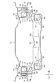
- FIG. 3 is a bottom view of the rear part of the vehicle body in which the rear subframe according to the embodiment of the present invention is incorporated, as viewed from the bottom side.
- FIG. 2 is a bottom view with the rear subframe shown in FIG. 1 removed.
- FIG. 3 is a longitudinal sectional view taken along the line III-III of FIG. 1.
- FIG. 4 is a longitudinal sectional view taken along the line IV-IV in FIG. 2. It is an expansion perspective view showing the partition member arranged in the closed section of a load transmission member.
- FIG. 1 is a bottom view of the rear portion of the vehicle body in which the rear subframe according to the embodiment of the present invention is incorporated, as viewed from the bottom side
- FIG. 2 is a bottom view with the rear subframe shown in FIG. 1 removed.
- front and rear indicates the vehicle front and rear direction
- left and right indicates the vehicle width direction (left and right direction)
- up and down indicates the vehicle vertical direction (vertical vertical direction).
- a rear subframe (subframe) 10 As shown in FIG. 1, a rear subframe (subframe) 10, a pair of left and right vehicle body side frames 12, 12, and a vehicle body cross member 14 are arranged at the rear of the vehicle body. Have been.
- a substantially flat rear floor panel 13 is disposed between the pair of left and right vehicle body side frames 12, 12 in the vehicle width direction.
- a pair of left and right vehicle body side frames 12, 12 are arranged on the vehicle body side and extend in the vehicle front-rear direction.
- a bent portion 15 is provided in the middle of each vehicle body side frame 12 extending along the vehicle front-rear direction. The bent portion 15 is directed obliquely to the front of the vehicle and is bent outward in the vehicle width direction.
- Each vehicle body side frame 12 includes a pair of left and right rear side frames 16, 16 and a pair of left and right side sills 18, 18, which are connected to each other in the left and right body side portions in the vehicle front-rear direction.
- the vehicle body cross member 14 extends in the vehicle width direction between the pair of left and right vehicle body side frames 12, 12.
- the left and right outer ends of the vehicle body cross member 14 along the vehicle width direction are respectively attached to portions located on the vehicle front side with respect to the bent portions 15 of the vehicle body side frames 12. Further, a portion closer to the center than the left and right outer ends of the vehicle body cross member 14 is attached to each vertical member 20.
- a load transmitting member 17 is disposed at a vehicle rear portion where a vehicle front side intermediate portion 50 of each vehicle body side frame 12 and a vehicle width direction outer portion 52 of the vehicle body cross member 14 intersect. Have been.
- the load transmitting members 17 are symmetrically arranged on both left and right sides along the vehicle width direction.
- the load transmitting member 17 has a substantially triangular shape when viewed from the bottom, and first to third flange portions 19a to 19c are provided along three sides.
- the load transmitting member 17 is formed so that the dimension in the vehicle width direction on the vehicle front side is the widest when viewed from the bottom, and gradually narrows and tapers toward the vehicle rear side.
- the first flange portion 19 a located on the vehicle front side when viewed from the bottom is joined to the vehicle width direction outer portion 52 of the vehicle body cross member 14.
- the second flange portion 19b located on the outer side in the vehicle width direction is joined to the vehicle front side intermediate portion 50 of the vehicle body side frame 12.
- FIG. 3 is a longitudinal sectional view taken along the line III-III of FIG. 1
- FIG. 4 is a longitudinal sectional view taken along the line IV-IV of FIG.
- FIG. 3 shows the depth of the vertical member 20.
- the third flange portion 19c located on the inside in the vehicle width direction is joined to the vehicle width direction outer portion 54 of the rear floor panel 13.
- the load transmitting member 17 is located between the bent portion 15 toward the vehicle front side and the vehicle body side frame 12 (vehicle front side intermediate portion 50) and the vehicle width direction outer end of the vehicle body cross member 14. It is connected to the center part in the width direction (outside part 54 in the vehicle width direction).
- the load transmitting member 17 has a substantially L-shaped cross section along the vehicle width direction (see FIGS. 3 and 4), and a vertical wall portion 17a and a horizontal wall portion 17b which are orthogonal to each other are formed continuously. I have. As shown in FIG. 4, the vertical wall portion 17a is joined to the vehicle width direction outer portion 54 of the rear floor panel 13 via the third flange portion 19c. The lateral wall portion 17b is joined to a side wall (vehicle front side intermediate portion 50) recessed inside the vehicle body side frame 12 via the second flange portion 19b.
- the load transmitting member 17 (vertical wall portion 17a, horizontal wall portion 17b) having a substantially L-shaped cross section, the vehicle front side intermediate portion 50 of each vehicle body side frame 12, and the vehicle width direction outer portion 54 of the rear floor panel 13 are provided.
- a closed section 58 having a closed section 56 closed by three members is provided.
- the rear subframe 10 is located inside the pair of left and right vehicle body side frames 12, 12 along the vehicle width direction, and is attached to the lower side of the pair of left and right vehicle body side frames 12, 12. Have been. Further, the rear sub-frame 10 supports a rear wheel suspension device (not shown) and also supports a power unit (a driving source such as a motor or an engine) via a vibration isolator (not shown).
- a power unit a driving source such as a motor or an engine
- the rear subframe 10 includes a pair of left and right vertical members 20, 20 extending along the vehicle front-rear direction, and a cross extending along the vehicle width direction between the pair of left and right vertical members 20, 20. And a member.
- the cross member includes a front cross member 22 (sub-frame cross member) fixed to a pair of left and right vertical members 20 and 20 on the vehicle front side, and a rear cross member fixed to a pair of left and right vertical members 20 and 20 on the vehicle rear side. And a cross member 24.
- the front cross member 22 has a first mounting portion 26, an extension portion 28, and a second mounting portion 30.
- the first mounting portion 26 is attached to each vertical member 20 at a position closer to the center on the left and right end sides along the vehicle width direction of the front cross member 22.
- the front cross member 22 has a substantially rectangular through hole 32 when viewed from the side in the vehicle front-rear direction.
- the through holes 32 are formed to penetrate the front wall of the front cross member 22 facing the front of the vehicle and the rear wall of the front cross member 22 facing the rear of the vehicle along the vehicle front-rear direction.
- each vertical member 20 is attached through the through hole 32 of the front cross member 22. That is, the vehicle front portion 20 a of each vertical member 20 is fitted into the through hole 32 of the front cross member 22. Further, the shape of the through hole 32 of the front cross member 22 corresponds to the cross-sectional shape of the vertical member 20 at the front portion 20a of the vehicle, which is perpendicular to the axis.
- the extension portion 28 extends from the first attachment portion 26 so as to rise outwardly in the vehicle width direction and upward.
- the second mounting portion 30 is mounted to the load transmitting member 17 at the vehicle width direction outer end of the extension portion 28. That is, a cylindrical first collar member (color member) 36 having the first through hole 34 is fixed in the closed cross section 56 formed by the load transmitting member 17 and the like. The first collar member 36 vertically connects the inside of the closed cross section 56 of the load transmitting member 17. The first collar member 36 is attached to a partition member 60 described later. A cylindrical second collar member 40 having a second through hole 38 is fixed in the closed cross section 23 of the front cross member 22. The second collar member 40 vertically connects the inside of the closed cross section 23 of the front cross member 22.
- the first collar member 36 and the second collar member 40 are coaxially arranged so as to overlap in the vertical direction.
- the front cross member 22 is fixed to the load transmitting member 17 by fastening bolts and nuts (not shown) that pass through the first through hole 34 and the second through hole 38 of the first collar member 36 and the second collar member 40. Have been.
- the front cross member 22 includes an upper cross member portion 22a on the upper side and a lower cross member portion 22b on the lower side.
- a closed closed section 23 is formed inside the upper cross member 22a and the lower cross member 22b (see FIG. 3).
- the rear cross member 24 is provided with a closed cross-section (not shown) having a closed cross-section by an upper wall having a substantially U-shaped vertical cross section and a lower wall having a substantially U-shaped vertical cross section. ing.
- Each vertical member 20 includes an upper wall 20b having a substantially U-shaped cross section and a lower wall 20c having a substantially U-shaped cross section.
- the upper wall portion 20b and the lower wall portion 20c are integrally connected (joined) via a flange portion, and a closed cross section 21 is formed therein (see FIG. 3).
- the vehicle front end 20d of each vertical member 20 is provided in a front open state located outside the vehicle rear end 20e of each vertical member 20 in the vehicle width direction.
- Each vertical member 20 extends along each vehicle body side frame 12 at a position separated from the vehicle body side frame 12 by a predetermined distance toward the center of the vehicle width (see FIG. 1).
- FIG. 5 is an enlarged perspective view showing a partition member disposed in a closed cross section of the load transmitting member.
- a partition member 60 extending along the vehicle width direction is disposed in the closed cross section 56 of the load transmitting member 17.
- the partition member 60 is disposed between the vehicle front side intermediate portion 50 of each vehicle body side frame 12 and the vertical wall portion 17 a of the load transmitting member 17.
- the partition wall member 60 includes a partition wall main body 62 having a flat plate shape along the vehicle width direction, and first and second bonding flange portions 64a and 64 provided at both ends of the partition wall main body 62 along the vehicle width direction.
- the curved portion 66 has a substantially arc-shaped cross section and extends along the up-down direction.
- the first joint flange portion 64a located on the inner side in the vehicle width direction is joined to the vertical wall portion 17a of the load transmitting member 17.
- the second joint flange portion 64b located outside in the vehicle width direction is joined to the vehicle front side intermediate portion 50 of the vehicle body side frame 12.
- the third joint flange portion 64c located at the bottom of the partition main body 62 is joined to the lateral wall portion 17b of the load transmitting member 17.
- first collar member 36 that connects the inside of the closed section 56 in the up-down direction is provided in the closed section 58.
- the first collar member 36 is joined to the curved portion 66 of the partition member 60.
- the second attachment portion 30 of the front cross member 22 is attached to the partition member 60 and / or the first collar member 36.
- the rear subframe 10 according to the present embodiment is basically configured as described above, and the operation and effect thereof will be described next.
- each vehicle body side frame 12 vehicle front side middle portion 50
- vehicle width direction center side of the vehicle width direction outer end of the vehicle body cross member 14. The vehicle width direction outer portion 52
- the front cross member 22 has a first attachment portion 26, an extension portion 28, and a second attachment portion 30.
- the support rigidity of the rear subframe 10 with respect to the vehicle body can be increased.
- the rigidity and strength of the rear portion of the vehicle body can be improved while suppressing an increase in the weight of the entire vehicle and a rise in manufacturing cost.
- the front cross member 22 is attached to the load transmitting member 17 having high rigidity and strength via the second attaching portion 30. Thereby, in this embodiment, the mounting rigidity and mounting strength of the front cross member 22 can be further improved.
- the load transmitting member 17 is provided with the closed cross section 58 having the closed cross section 56 closed by each vehicle body side frame 12 and the rear floor panel 13.
- the load transmitting member 17 vertical wall portion 17a, horizontal wall portion 17b having a substantially L-shaped cross section, the vehicle front side intermediate portion 50 of each vehicle body side frame 12, and the vehicle width direction of the rear floor panel 13
- a closed cross-section 58 having a closed cross-section 56 closed by three members including an outer portion 54 is provided.
- the rigidity and strength of the load transmitting member 17 can be increased, and the mounting of the second mounting portion 30 for mounting the front cross member 22 to the load transmitting member 17 can be achieved. Rigidity and mounting strength can be improved.
- the partition member 60 extending along the vehicle width direction is disposed in the closed cross-section 58 formed by the load transmitting member 17 and the like.
- the second attachment part 30 is attached to the partition wall member 60.
- the rigidity and strength of the load transmitting member 17 are increased by providing the partition member 60, and the mounting rigidity and the mounting strength of the second mounting portion 30 for mounting the front cross member 22 to the load transmitting member 17 are improved. It can be further improved.
- the first collar member 36 that connects the inside of the closed cross section 58 in the up-down direction is provided, and the second attachment portion 30 is attached to the first collar member 36.
- the rigidity and strength of the load transmitting member 17 are increased, and the mounting rigidity and mounting of the second mounting portion 30 for attaching the front cross member 22 to the load transmitting member 17 are provided. The strength can be further improved.
- the rigidity and strength of the load transmitting member 17 can be increased by providing the partition member 60 and the first collar member 36 in the closed cross section 58, respectively.
- the mounting rigidity and the mounting strength of the second mounting portion 30 for mounting the front cross member 22 to the load transmitting member 17 can be further improved.
- Rear subframe DESCRIPTION OF SYMBOLS 12 Body side frame 13 Rear floor panel 14 Body cross member 15 Bending part 17 Load transmission member 20 Vertical member 22 Front cross member (subframe cross member) 26 first attachment portion 28 extension portion 30 second attachment portion 36 first collar member (collar member) 56 Closed section 58 Closed section 60 Partition member
Landscapes
- Engineering & Computer Science (AREA)
- Chemical & Material Sciences (AREA)
- Combustion & Propulsion (AREA)
- Transportation (AREA)
- Mechanical Engineering (AREA)
- Body Structure For Vehicles (AREA)
Abstract
屈曲部(15)を有する左右一対の車体側部フレーム(12、12)と、左右一対の車体側部フレームの間で車幅方向に沿って延びる車体クロスメンバ(14)と、屈曲部から車両前方側に向かう各車体側部フレームの部位と、車体クロスメンバの車幅方向外側端部よりも車幅方向中央側の部位とを連結する荷重伝達部材(17)と、各車体側部フレームに沿うように延びる左右一対の縦メンバ(20、20)と、左右一対の縦メンバの間で車幅方向に延びる前クロスメンバ(22)とを備え、前クロスメンバは、各縦メンバに対して取り付けられる第1取付部(26)と、第1取付部から車幅方向に沿って延びる延長部(28)と、延長部の車幅方向外側端部で荷重伝達部材に対して取り付けられている第2取付部(30)とを有する。
Description
本発明は、例えば、自動車等の車両に搭載されるサブフレーム構造に関する。
例えば、特許文献1には、左右一対のリヤサイドフレームの車幅方向に沿った間に、後突時の衝突荷重を分散、吸収するリヤサブフレーム(ペリメータフレーム)を設けた車体後部構造が開示されている。
特許文献1に開示されたリヤサブフレーム(ペリメータフレーム)は、左右車両前端部及び左右車両後端部がそれぞれリヤサイドフレームに連結された一対の側方フレームと、一対の側方フレーム間に連結された前方フレーム及び後方フレームとによって構成されている。
ところで、特許文献1に開示された車体後部構造では、リヤサブフレームが車体に対して車両前後、且つ、左右一対の合計4点(取付点が4点)で取り付けられている。
このようなリヤサブフレームの4点支持構造では、例えば、リヤサブフレームに搭載される部品の重量が増加した場合、十分な剛性・強度を得ることができず、乗り心地や操縦安定性が低下するおそれがある。
本発明は、前記の点に鑑みてなされたものであり、車両全体の重量増加及び製造コストの高騰を抑制しつつ、車体後部の剛性・強度を向上させることが可能なサブフレーム構造を提供することを目的とする。
前記の目的を達成するために、本発明は、車体側部に配置され、車両前後方向に延びる途中に車幅方向外側に向かって屈曲する屈曲部を有する左右一対の車体側部フレームと、前記左右一対の車体側部フレームの間で車幅方向に沿って延びると共に、車幅方向外側端部が前記屈曲部よりも車両前方側に取り付けられた車体クロスメンバと、前記屈曲部から車両前方側に向かう前記各車体側部フレームの部位と、前記車体クロスメンバの車幅方向外側端部よりも車幅方向中央側の部位とを連結する荷重伝達部材と、前記各車体側部フレームから車幅中央側に所定距離だけ離間した位置で前記各車体側部フレームに沿うように延びる左右一対の縦メンバと、前記左右一対の縦メンバの間で車幅方向に延びるサブフレームクロスメンバと、を備え、前記サブフレームクロスメンバは、第1取付部と、延長部と、第2取付部とを有し、前記第1取付部は、前記各縦メンバに対して取り付けられ、前記延長部は、前記第1取付部から車幅方向に沿って延びており、前記第2取付部は、前記延長部の車幅方向外側端部で前記荷重伝達部材に対して取り付けられていることを特徴とする。
本発明では、車両全体の重量増加及び製造コストの高騰を抑制しつつ、車体後部の剛性・強度を向上させることが可能なサブフレーム構造を得ることができる。
次に、本発明の実施形態について、適宜図面を参照しながら詳細に説明する。
図1は、本発明の実施形態に係るリヤサブフレームが組み込まれた車体後部を底面側からみた底面図、図2は、図1に示すリヤサブフレームを取り除いた底面図である。なお、各図中において、「前後」は、車両前後方向、「左右」は、車幅方向(左右方向)、「上下」は、車両上下方向(鉛直上下方向)を、それぞれ示している。
図1に示されるように、車体後部には、本発明の実施形態に係るリヤサブフレーム(サブフレーム)10と、左右一対の車体側部フレーム12、12と、車体クロスメンバ14とがそれぞれ配置されている。左右一対の車体側部フレーム12、12の車幅方向に沿った間には、略平面状を呈するリヤフロアパネル13が配置されている。
左右一対の車体側部フレーム12、12は、車体側部に配置され、車両前後方向に延びている。各車体側部フレーム12の車両前後方向に沿って延びる途中には、屈曲部15が設けられている。この屈曲部15は、車両前方斜め方向に指向し、且つ、車幅方向外側に向かって屈曲している。各車体側部フレーム12は、左右一対のリヤサイドフレーム16、16と、左右一対のサイドシル18、18とを含み、これらが左右の車体側部において車両前後方向で連結されている。
車体クロスメンバ14は、左右一対の車体側部フレーム12、12の間で車幅方向に延びている。また、車体クロスメンバ14の車幅方向に沿った左右外側端部は、各車体側部フレーム12の屈曲部15よりも車両前方側に位置する部位に対してそれぞれ取り付けられている。さらに、車体クロスメンバ14の左右外側端部よりも中央寄りの部位は、各縦メンバ20に対して取り付けられている。
図2に示されるように、各車体側部フレーム12の車両前方側中間部50と、車体クロスメンバ14の車幅方向外側部52とが交差する車両後方部位には、荷重伝達部材17が配置されている。荷重伝達部材17は、車幅方向に沿った左右両側にそれぞれ対称に配置されている。この荷重伝達部材17は、底面視して略三角形状を呈し、3つの辺部に沿って第1~第3フランジ部19a~19cが設けられている。また、荷重伝達部材17は、底面視して、車両前方側の車幅方向の寸法が最も幅広で、車両後方側に向かうにつれて徐々に幅狭で先細りするように形成されている。
底面視して、車両前方側に位置する第1フランジ部19aは、車体クロスメンバ14の車幅方向外側部52に接合されている。車幅方向外側に位置する第2フランジ部19bは、車体側部フレーム12の車両前方側中間部50に接合されている。
図3は、図1のIII-III線に沿った縦断面図、図4は、図2のIV-IV線に沿った縦断面図である。なお、図3では、縦メンバ20の奥行きを示している。
図3に示されるように、車幅方向内側に位置する第3フランジ部19cは、リヤフロアパネル13の車幅方向外側部54に接合されている。これにより、荷重伝達部材17は、屈曲部15から車両前方側に向かう各車体側部フレーム12の部位(車両前方側中間部50)と、車体クロスメンバ14の車幅方向外側端部よりも車幅方向中央側の部位(車幅方向外側部54)とを連結している。
また、荷重伝達部材17は、車幅方向に沿った断面が略L字状を呈し(図3、図4参照)、互いに直交する縦壁部17aと横壁部17bとが連続して形成されている。図4に示されるように、縦壁部17aは、第3フランジ部19cを介してリヤフロアパネル13の車幅方向外側部54に接合されている。横壁部17bは、第2フランジ部19bを介して車体側部フレーム12の内側に窪んだ側壁(車両前方側中間部50)に接合されている。この断面略L字状を呈する荷重伝達部材17(縦壁部17a、横壁部17b)と、各車体側部フレーム12の車両前方側中間部50と、リヤフロアパネル13の車幅方向外側部54とからなる三者によって閉塞された閉断面56を有する閉断面部58が設けられている。
図1に戻り、リヤサブフレーム10は、左右一対の車体側部フレーム12、12の車幅方向に沿った内側に位置し、且つ、左右一対の車体側部フレーム12、12の下方側に取り付けられている。また、リヤサブフレーム10は、図示しない後輪用懸架装置を支持すると共に、図示しない防振装置を介して図示しないパワーユニット(モータやエンジン等の駆動源)を支持している。
図1に示されるように、リヤサブフレーム10は、車両前後方向に沿って延びる左右一対の縦メンバ20、20と、左右一対の縦メンバ20、20の間で車幅方向に沿って延びるクロスメンバとを備えて構成されている。このクロスメンバは、左右一対の縦メンバ20、20の車両前方側に固定される前クロスメンバ22(サブフレームクロスメンバ)と、左右一対の縦メンバ20、20の車両後方側に固定される後クロスメンバ24とを有する。
図3に示されるように、前クロスメンバ22は、第1取付部26と、延長部28と、第2取付部30とを有している。
第1取付部26は、前クロスメンバ22の車幅方向に沿った左右端部側で中央部寄りの部位が、各縦メンバ20に対して取り付けられている。前クロスメンバ22は、車両前後方向から側面視して略矩形状の貫通孔32を有する。この貫通孔32は、車両前方に臨む前クロスメンバ22の前壁、及び、車両後方に臨む前クロスメンバ22の後壁にそれぞれ車両前後方向に沿って貫通するように形成されている。
各縦メンバ20の車両前方部20aは、前クロスメンバ22の貫通孔32を貫通して取り付けられている。すなわち、各縦メンバ20の車両前方部20aは、前クロスメンバ22の貫通孔32に対して嵌挿されている。また、前クロスメンバ22の貫通孔32の形状は、各縦メンバ20の車両前方部20aの軸直断面形状に対応している。
延長部28は、第1取付部26から車幅方向外側で且つ上方側に向けて立ち上がるように延びている。
第2取付部30は、延長部28の車幅方向外側端部で荷重伝達部材17に対して取り付けられている。すなわち、荷重伝達部材17等によって形成された閉断面56内には、第1貫通孔34を有する円筒状の第1カラー部材(カラー部材)36が固定されている。第1カラー部材36は、荷重伝達部材17の閉断面56内を上下方向で連結している。この第1カラー部材36は、後記する隔壁部材60に取り付けられている。また、前クロスメンバ22の閉断面23内には、第2貫通孔38を有する円筒状の第2カラー部材40が固定されている。第2カラー部材40は、前クロスメンバ22の閉断面23内を上下方向で連結している。
第1カラー部材36及び第2カラー部材40は、それぞれ同軸状で上下方向に重畳するように配置されている。第1カラー部材36及び第2カラー部材40の第1貫通孔34及び第2貫通孔38を貫通する図示しないボルト及びナットを締結することで、前クロスメンバ22が荷重伝達部材17に対して固定されている。
さらに、前クロスメンバ22は、上部側の上クロスメンバ部22aと、下部側の下クロスメンバ部22bとによって構成されている。上クロスメンバ部22a及び下クロスメンバ部22bの内部には、閉塞された閉断面23が形成されている(図3参照)。
後クロスメンバ24は、軸直断面が略コ字状に形成された上壁と、軸直断面が略コ字状に形成された下壁とによって閉断面を有する図示しない閉断面部が設けられている。
左右一対の縦メンバ20、20は、同一構成からなり、それぞれ左右対称に配置されている。各縦メンバ20は、断面略コ字を呈する上壁部20bと、断面略コ字状を呈する下壁部20cとによって構成されている。上壁部20bと下壁部20cとは、フランジ部を介して一体的に結合(接合)され、その内部に閉断面21が形成されている(図3参照)。また、各縦メンバ20の車両前方端部20dは、各縦メンバ20の車両後方端部20eよりも車幅方向外側に位置する前開き状態に設けられている。
各縦メンバ20は、各車体側部フレーム12から車幅中央側に所定距離だけ離間した位置で各車体側部フレーム12に沿うように延びている(図1参照)。
荷重伝達部材の閉断面部内に配置された隔壁部材を示す拡大斜視図である。
図4及び図5に示されるように、荷重伝達部材17の閉断面56内には、車幅方向に沿って延びる隔壁部材60が配置されている。隔壁部材60は、各車体側部フレーム12の車両前方側中間部50と、荷重伝達部材17の縦壁部17aとの間に配置されている。
隔壁部材60は、車幅方向に沿って平板状を呈する隔壁本体部62と、隔壁本体部62の車幅方向に沿った両端部にそれぞれ設けられた第1接合フランジ部64a及び第2接合フランジ部64bと、隔壁本体部62の底部に設けられた第3接合フランジ部64cと、隔壁本体部62の車幅方向に沿った中間部に設けられた湾曲部66とを有する。湾曲部66は、断面略円弧状を呈し上下方向に沿って延びている。
車幅方向内側に位置する第1接合フランジ部64aは、荷重伝達部材17の縦壁部17aに接合されている。車幅方向外側に位置する第2接合フランジ部64bは、車体側部フレーム12の車両前方側中間部50に接合されている。隔壁本体部62の底部に位置する第3接合フランジ部64cは、荷重伝達部材17の横壁部17bに接合されている。
また、閉断面部58には、閉断面56内を上下方向に連結する第1カラー部材36が設けられている。第1カラー部材36は、隔壁部材60の湾曲部66に対して接合されている。前クロスメンバ22の第2取付部30は、隔壁部材60及び/又は第1カラー部材36に対して取り付けられている。
本実施形態に係るリヤサブフレーム10は、基本的に以上のように構成されるものであり、次にその作用効果について説明する。
本実施形態では、屈曲部15から車両前方側に向かう各車体側部フレーム12の部位(車両前方側中間部50)と、車体クロスメンバ14の車幅方向外側端部よりも車幅方向中央側の部位(車幅方向外側部52)とを連結する荷重伝達部材17を設けている。また、本実施形態では、前クロスメンバ22が、第1取付部26と、延長部28と、第2取付部30とを有している。
本実施形態では、前クロスメンバ22を、縦メンバ20と、荷重伝達部材17を介して車体側部フレーム12との両方に取り付けることで、車体に対するリヤサブフレーム10の支持剛性を高めることができる。この結果、本実施形態では、車両全体の重量増加及び製造コストの高騰を抑制しつつ、車体後部の剛性・強度を向上させることができる。
また、前クロスメンバ22を、第2取付部30を介して剛性・強度が高い荷重伝達部材17に対して取り付けている。これにより、本実施形態では、前クロスメンバ22の取付剛性・取付強度をより向上させることができる。
また、本実施形態では、荷重伝達部材17に、各車体側部フレーム12と、リヤフロアパネル13とによって閉塞された閉断面56を有する閉断面部58が設けられている。具体的には、断面略L字状を呈する荷重伝達部材17(縦壁部17a、横壁部17b)と、各車体側部フレーム12の車両前方側中間部50と、リヤフロアパネル13の車幅方向外側部54とからなる三者によって閉塞された閉断面56を有する閉断面部58が設けられている。
本実施形態では、この閉断面56を設けることで、荷重伝達部材17の剛性・強度を高めることができ、前クロスメンバ22を荷重伝達部材17に対して取り付けている第2取付部30の取付剛性・取付強度を向上させることができる。
さらに、本実施形態では、荷重伝達部材17等によって形成された閉断面部58内に、車幅方向に沿って延びる隔壁部材60が配置されている。第2取付部30は、隔壁部材60に対して取り付けられている。本実施形態では、隔壁部材60を設けることで荷重伝達部材17の剛性・強度が高まり、前クロスメンバ22を荷重伝達部材17に対して取り付けている第2取付部30の取付剛性・取付強度をより一層向上させることができる。
さらにまた、本実施形態では、閉断面部58内を上下方向に連結する第1カラー部材36を設け、第2取付部30が、第1カラー部材36に対して取り付けられている。本実施形態では、第1カラー部材36を設けることで荷重伝達部材17の剛性・強度が高まり、前クロスメンバ22を荷重伝達部材17に対して取り付けている第2取付部30の取付剛性・取付強度をより一層向上させることができる。
さらにまた、本実施形態では、閉断面部58内に隔壁部材60及び第1カラー部材36をそれぞれ設けることで、荷重伝達部材17の剛性・強度を高めることができる。これにより、本実施形態では、前クロスメンバ22を荷重伝達部材17に対して取り付けている第2取付部30の取付剛性・取付強度をより一層向上させることができる。
10 リヤサブフレーム(サブフレーム)
12 車体側部フレーム
13 リヤフロアパネル
14 車体クロスメンバ
15 屈曲部
17 荷重伝達部材
20 縦メンバ
22 前クロスメンバ(サブフレームクロスメンバ)
26 第1取付部
28 延長部
30 第2取付部
36 第1カラー部材(カラー部材)
56 閉断面
58 閉断面部
60 隔壁部材
12 車体側部フレーム
13 リヤフロアパネル
14 車体クロスメンバ
15 屈曲部
17 荷重伝達部材
20 縦メンバ
22 前クロスメンバ(サブフレームクロスメンバ)
26 第1取付部
28 延長部
30 第2取付部
36 第1カラー部材(カラー部材)
56 閉断面
58 閉断面部
60 隔壁部材
Claims (5)
- 車体側部に配置され、車両前後方向に延びる途中に車幅方向外側に向かって屈曲する屈曲部を有する左右一対の車体側部フレームと、
前記左右一対の車体側部フレームの間で車幅方向に沿って延びると共に、車幅方向外側端部が前記屈曲部よりも車両前方側に取り付けられた車体クロスメンバと、
前記屈曲部から車両前方側に向かう前記各車体側部フレームの部位と、前記車体クロスメンバの車幅方向外側端部よりも車幅方向中央側の部位とを連結する荷重伝達部材と、
前記各車体側部フレームから車幅中央側に所定距離だけ離間した位置で前記各車体側部フレームに沿うように延びる左右一対の縦メンバと、
前記左右一対の縦メンバの間で車幅方向に延びるサブフレームクロスメンバと、
を備え、
前記サブフレームクロスメンバは、第1取付部と、延長部と、第2取付部とを有し、
前記第1取付部は、前記各縦メンバに対して取り付けられ、
前記延長部は、前記第1取付部から車幅方向に沿って延びており、
前記第2取付部は、前記延長部の車幅方向外側端部で前記荷重伝達部材に対して取り付けられていることを特徴とするサブフレーム構造。 - 請求項1記載のサブフレーム構造において、
車体底部に架設されたリヤフロアパネルを備え、
前記荷重伝達部材には、前記各車体側部フレームと、前記リヤフロアパネルとによって閉塞された閉断面を有する閉断面部が設けられていることを特徴とするサブフレーム構造。 - 請求項2記載のサブフレーム構造において、
前記閉断面部内には、車幅方向に沿って延びる隔壁部材が配置され、
前記第2取付部は、前記隔壁部材に対して取り付けられていることを特徴とするサブフレーム構造。 - 請求項2記載のサブフレーム構造において、
前記閉断面部内を上下方向に連結するカラー部材を備え、
前記第2取付部は、前記カラー部材に対して取り付けられていることを特徴とするサブフレーム構造。 - 請求項2記載のサブフレーム構造において、
前記閉断面部内には、車幅方向に延びる隔壁部材が配置され、
前記隔壁部材に対し、前記閉断面部内を上下方向に連結するカラー部材が取り付けられ、
前記第2取付部は、前記カラー部材に対して取り付けられていることを特徴とするサブフレーム構造。
Priority Applications (4)
| Application Number | Priority Date | Filing Date | Title |
|---|---|---|---|
| JP2020547781A JP7022841B2 (ja) | 2018-09-27 | 2018-09-27 | サブフレーム構造 |
| PCT/JP2018/036154 WO2020065899A1 (ja) | 2018-09-27 | 2018-09-27 | サブフレーム構造 |
| CN201880097937.1A CN112752701B (zh) | 2018-09-27 | 2018-09-27 | 车身后部构造 |
| US17/279,242 US11745800B2 (en) | 2018-09-27 | 2018-09-27 | Subframe structure |
Applications Claiming Priority (1)
| Application Number | Priority Date | Filing Date | Title |
|---|---|---|---|
| PCT/JP2018/036154 WO2020065899A1 (ja) | 2018-09-27 | 2018-09-27 | サブフレーム構造 |
Publications (1)
| Publication Number | Publication Date |
|---|---|
| WO2020065899A1 true WO2020065899A1 (ja) | 2020-04-02 |
Family
ID=69950426
Family Applications (1)
| Application Number | Title | Priority Date | Filing Date |
|---|---|---|---|
| PCT/JP2018/036154 Ceased WO2020065899A1 (ja) | 2018-09-27 | 2018-09-27 | サブフレーム構造 |
Country Status (4)
| Country | Link |
|---|---|
| US (1) | US11745800B2 (ja) |
| JP (1) | JP7022841B2 (ja) |
| CN (1) | CN112752701B (ja) |
| WO (1) | WO2020065899A1 (ja) |
Families Citing this family (2)
| Publication number | Priority date | Publication date | Assignee | Title |
|---|---|---|---|---|
| FR3142985A1 (fr) * | 2022-12-09 | 2024-06-14 | Psa Automobiles Sa | Train arrière de véhicule automobile fixé par une entretoise cubique à l’intérieur du longeronnet |
| JP2025134456A (ja) * | 2024-03-04 | 2025-09-17 | 株式会社Subaru | パイプナットの固定構造 |
Citations (3)
| Publication number | Priority date | Publication date | Assignee | Title |
|---|---|---|---|---|
| JPS62192979U (ja) * | 1986-05-30 | 1987-12-08 | ||
| JPS648475U (ja) * | 1987-07-06 | 1989-01-18 | ||
| JPH0439968U (ja) * | 1990-08-03 | 1992-04-06 |
Family Cites Families (11)
| Publication number | Priority date | Publication date | Assignee | Title |
|---|---|---|---|---|
| JPH10297541A (ja) | 1997-04-23 | 1998-11-10 | Toyota Motor Corp | 車両のリヤアンダボデー構造 |
| DE602008000209D1 (de) * | 2007-10-10 | 2009-11-26 | Honda Motor Co Ltd | Vorderteilkonstruktion einer Fahrzeugkarosserie |
| JP4951461B2 (ja) | 2007-10-18 | 2012-06-13 | 本田技研工業株式会社 | 車体前部構造 |
| JP5456357B2 (ja) * | 2009-04-14 | 2014-03-26 | 本田技研工業株式会社 | 自動車の後部車体構造 |
| JP5156729B2 (ja) | 2009-12-16 | 2013-03-06 | 本田技研工業株式会社 | サブフレーム構造 |
| JP5499726B2 (ja) | 2010-01-18 | 2014-05-21 | マツダ株式会社 | 電気自動車の後部構造 |
| US9663050B2 (en) | 2013-01-25 | 2017-05-30 | Toyota Jidosha Kabushiki Kaisha | Vehicle body front section structure |
| WO2015037130A1 (ja) | 2013-09-13 | 2015-03-19 | 本田技研工業株式会社 | 車体後部構造 |
| JP6102951B2 (ja) | 2015-01-16 | 2017-03-29 | マツダ株式会社 | 車両のサブフレーム構造 |
| JP6288069B2 (ja) | 2015-12-25 | 2018-03-07 | トヨタ自動車株式会社 | 車体後部構造 |
| JP6636866B2 (ja) * | 2016-06-24 | 2020-01-29 | 本田技研工業株式会社 | 車体前部構造 |
-
2018
- 2018-09-27 WO PCT/JP2018/036154 patent/WO2020065899A1/ja not_active Ceased
- 2018-09-27 US US17/279,242 patent/US11745800B2/en active Active
- 2018-09-27 JP JP2020547781A patent/JP7022841B2/ja active Active
- 2018-09-27 CN CN201880097937.1A patent/CN112752701B/zh not_active Expired - Fee Related
Patent Citations (3)
| Publication number | Priority date | Publication date | Assignee | Title |
|---|---|---|---|---|
| JPS62192979U (ja) * | 1986-05-30 | 1987-12-08 | ||
| JPS648475U (ja) * | 1987-07-06 | 1989-01-18 | ||
| JPH0439968U (ja) * | 1990-08-03 | 1992-04-06 |
Also Published As
| Publication number | Publication date |
|---|---|
| US11745800B2 (en) | 2023-09-05 |
| JP7022841B2 (ja) | 2022-02-18 |
| US20220048571A1 (en) | 2022-02-17 |
| CN112752701B (zh) | 2023-01-24 |
| CN112752701A (zh) | 2021-05-04 |
| JPWO2020065899A1 (ja) | 2021-08-30 |
Similar Documents
| Publication | Publication Date | Title |
|---|---|---|
| CN104203724B (zh) | 汽车的前副车架结构 | |
| CN105339242B (zh) | 车辆用的副车架 | |
| JP6865837B2 (ja) | 車両後部構造 | |
| CN110304152B (zh) | 车辆的前部车身结构 | |
| KR20100045800A (ko) | 서스펜션용 서브 프레임 | |
| JPWO2011074527A1 (ja) | 車体フロア構造 | |
| KR101705146B1 (ko) | 차량용 서브프레임의 구조 | |
| JP2019006311A (ja) | 車体前部構造 | |
| JP2019171934A (ja) | 車両の前部車体構造 | |
| JP2019171931A (ja) | 車両の前部車体構造 | |
| JP7022841B2 (ja) | サブフレーム構造 | |
| JP7083035B2 (ja) | サブフレーム構造 | |
| JP2013241041A (ja) | 自動車の車体前部構造 | |
| JP2010167819A (ja) | 車両の下部車体構造 | |
| JP5321081B2 (ja) | 車両の下部車体構造 | |
| JP5141963B2 (ja) | 車体構造 | |
| JP7038220B2 (ja) | サブフレーム構造 | |
| JP2009107387A (ja) | 自動車の車体構造 | |
| JP2004224104A (ja) | 車両前部構造 | |
| KR101326517B1 (ko) | 자동차용 후륜 서브프레임 | |
| JP2020050209A (ja) | サブフレーム構造 | |
| JP2006224909A (ja) | 補強構造 | |
| JP2013119318A (ja) | 車体前部構造 | |
| JP2010202128A (ja) | シート台座 | |
| JP2009248636A (ja) | 車両用フロア構造 |
Legal Events
| Date | Code | Title | Description |
|---|---|---|---|
| 121 | Ep: the epo has been informed by wipo that ep was designated in this application |
Ref document number: 18935146 Country of ref document: EP Kind code of ref document: A1 |
|
| ENP | Entry into the national phase |
Ref document number: 2020547781 Country of ref document: JP Kind code of ref document: A |
|
| NENP | Non-entry into the national phase |
Ref country code: DE |
|
| 122 | Ep: pct application non-entry in european phase |
Ref document number: 18935146 Country of ref document: EP Kind code of ref document: A1 |