WO2020059690A1 - アイラッシュカーラー - Google Patents
アイラッシュカーラー Download PDFInfo
- Publication number
- WO2020059690A1 WO2020059690A1 PCT/JP2019/036322 JP2019036322W WO2020059690A1 WO 2020059690 A1 WO2020059690 A1 WO 2020059690A1 JP 2019036322 W JP2019036322 W JP 2019036322W WO 2020059690 A1 WO2020059690 A1 WO 2020059690A1
- Authority
- WO
- WIPO (PCT)
- Prior art keywords
- eyelash curler
- arm
- handle
- fixing member
- force
- Prior art date
- Legal status (The legal status is an assumption and is not a legal conclusion. Google has not performed a legal analysis and makes no representation as to the accuracy of the status listed.)
- Ceased
Links
Images





Classifications
-
- A—HUMAN NECESSITIES
- A45—HAND OR TRAVELLING ARTICLES
- A45D—HAIRDRESSING OR SHAVING EQUIPMENT; EQUIPMENT FOR COSMETICS OR COSMETIC TREATMENTS, e.g. FOR MANICURING OR PEDICURING
- A45D2/00—Hair-curling or hair-waving appliances ; Appliances for hair dressing treatment not otherwise provided for
- A45D2/48—Eyelash curlers; Eyebrow curlers
Definitions
- the present invention relates to an eyelash curler.
- an eyelash curler (eyelash curler, burer) has a configuration using the principle of leverage, and is formed of a metal such as stainless steel using two fingers.
- an object of the present invention is to provide a resin-made eyelash curler that can perform the same operation as that of a metal, while ensuring strength and without increasing the size of a general metal shape. .
- An eyelash curler is provided, in which the fixing member, the acting member, and the force member are each integrally formed of resin.
- the same operation as that of a metal eyelash curler can be performed without increasing the size of a general metal eyelasher while ensuring strength.
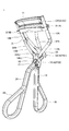
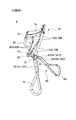
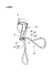
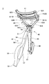
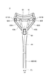
- FIG. 1 is an overall perspective view of an eyelash curler according to a first embodiment of the present invention (part 1). The whole perspective view of the eyelash curler of a 1st embodiment (the 2).
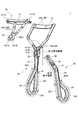
- FIG. 2 is an exploded view of the eyelash curler according to the first embodiment.
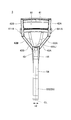
- FIG. 2 is a rear view of the eyelash curler according to the first embodiment.
- the figure which shows the cross section of the beam part of an eyelash curler The figure which shows the structural example of the eyelash curler of this invention in consideration of the ratio of the force in a power point member, and a movable angle.
- the whole perspective view (the 1) of the eyelash curler of a 2nd embodiment of the present invention The whole perspective view of the eyelash curler of a 2nd embodiment (the 2).
- the exploded view of the eyelash curler of a 2nd embodiment The front view of the eyelash curler of 2nd Embodiment.
- the present invention relates to a resin eyelash curler (eyelash curler for entire eyelashes, partial eyelash curler).
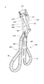
- FIG. 1 is an overall perspective view of an eyelash curler according to a first embodiment of the present invention.
- FIG. 2 is an overall perspective view of the eyelash curler of the first embodiment, viewed from a direction different from FIG.
- FIG. 3 is an exploded view of the eyelash curler of FIG.
- the eyelash curler 1 of the present embodiment has a configuration similar to a general metal eyelash curler, and is integrally formed for each member by a resin described later.
- the eyelash curler 1 has a fixing member 10, a power point member 20, and an action member 30.
- the fixing member (also referred to as a support portion) 10 has an upper press portion 11, parallel columns 12A and 12B, inclined columns 13A and 13B, an arm 14, and a handle 16.
- a support hole 15 is formed in the arm 14 as a handle.
- the arm 14 also exists above the support hole 15, and above the support hole 15 is a junction 141 ⁇ / b> J that merges with the inclined columns 13 ⁇ / b> A and 13 ⁇ / b> B.
- the upper press portion (also referred to as an abutting member, an upper clip, or a frame) 11 is a portion that abuts on the upper surface of the upper lash when curling the upper lash.
- the parallel struts 12A and 12B are integrally formed from both ends in the width direction of the upper press portion 11, and extend in the up-down direction.
- the upper ends of the inclined columns 13A and 13B are connected to the lower ends of the parallel columns 12A and 12B, the lower sides thereof are narrowed in a V-shape, and the lower ends are connected to the arm 14.
- the parallel columns 12A and 12B and the inclined columns 13A and 13B function as columns.
- the arm 14 (also referred to as a first arm portion, a handle portion, or a shaft portion) 14 is an extension portion that connects between the inclined supports 13A and 13B and the handle 16. Further, in this example, the arm 14 extends in the same direction as the straight portion 161 (see FIG. 3) which is an inner portion of the handle 16.
- the handle (handle, finger ring, handle, gripping portion) 16 has a ring shape in which a finger hole into which a finger enters is formed.
- a finger hole into which a finger enters is formed.
- the thumb of the user is often inserted into the finger hole of the handle 16.
- the index finger, the middle finger, or the ring finger of the practitioner is inserted into the finger hole of the handle 16.
- the fixing member 10 includes a handle 16, an arm 14 extending in the up-down direction, and a pair of columns 12 ⁇ / b> A, 13 ⁇ / b> A branching from the arm 14 and supporting both ends of the upper press unit 11. , 12B, 13B and the upper press portion 11 are integrally formed.
- small holes 151A, 151B are formed in the side surfaces (side walls) on both sides forming the support hole 15 formed in the arm 14 so as to penetrate in the width direction.
- the side surface that defines the support hole 15 is wider than the other part of the arm 14, but may have the same width as the other arm 14.
- the power point member 20 has arms 21 and 24 and a handle 25.
- the distal arm 21 has a distal hole (distal engaging hole) 22 as a first engaging hole and a fulcrum hole (fulcrum engaging hole) 23 as a second engaging hole.
- the arm portions (also referred to as a second arm portion, a handle portion, and a shaft portion) 21 and 24 have different extending directions from the distal arm 21 extending from the distal end beyond the connecting portion, and have a different holding direction. It has a central arm 24 that extends in the same direction as the straight portion 251 (see FIG. 3) that is the inner part of the hand 25.
- the distal arm 21 of the power point member 20 is inserted into the support hole 15 of the fixing member 10 from the distal end opposite to the handle 25, and the fulcrum hole 23 and the small side surface of the support hole 15 are formed.
- the holes 151A and 151B coincide with each other, the holes are locked by the pin shaft PS2 so as to pass through the fulcrum hole 23 and the small holes 151A and 151B.
- the power point member 20 can rotate with respect to the fixed member 10 about the pin axis PS2 as a rotation axis. That is, the power point member 20 rotates using the handle 25 as a power point, an engagement portion with the fixing member 10 as a fulcrum, and an upper end portion as an action point, using the first-type lever principle.
- the stress generation range includes the maximum stress generation point where the stress is maximized in use. Note that the stress generation range is a portion where a relatively large stress is generated, and the stress is also generated in other portions.
- the handle (handle, finger ring, handle, grip portion) 25 has a ring shape with a finger hole into which a finger enters.
- a finger hole into which a finger enters.
- the index finger, the middle finger, or the ring finger of the user is often inserted into the finger hole of the handle 25 when the user curls the upper eyelash by himself.
- the practitioner's thumb is often inserted into the handle 25 when the practitioner curls the eyelashes or curls the lower eyelashes by himself.
- the power point member 20 is formed integrally with a handle 25 and extending arm portions 21 and 24.
- the arm portions 21 and 24 are formed as one piece and have the same thickness as the handle 25. That's it.
- the distal arm 21 is provided with the fulcrum hole 23 serving as a fulcrum and the distal hole 22 serving as an action point, and the central arm 24 extends obliquely with respect to the distal arm 21. . Further, the central arm 24 extends in the same direction as the straight portion 251 (see FIG. 3) which is a portion inside the handle 25. Due to the inclination of the arms 21 and 24 of the power point member 20, the straight portion 251 of the handle 25 continuously extending from the arm 24 becomes substantially parallel to the straight portion 161 of the handle 16 continuously extending from the arm 14. Therefore, the force can be applied without waste.
- the handle 16 branches from the lower end of one arm 14 in the thickness direction y (see FIG. 6C) at a branch point BP1.
- the finger hole is formed by a straight portion 161 extending linearly from the arm 14 and a curved portion 162 which bulges from the lower end of the straight portion 161 in the first thickness direction and turns back to return to the branch point BP. ing.
- the handle 25 branches from the lower end of the central arm 24 of the single arm unit 21, 24 at a branch point BP ⁇ b> 2 in the thickness direction, and forms a central part of the arm unit.
- a straight portion 251 extending linearly from the arm 24, and a curved portion 252 which bulges from the lower end of the straight portion 251 in a second thickness direction opposite to the first thickness direction, returns and returns to the branch point BP2. are formed to form finger holes.
- the finger holes formed in the handles 16, 25 are tear-shaped.
- the operating member (interlocking section, elevating section) 30 has a lower press section 31, link sections 32A and 32B, and a connection section 33.
- the eyelash curler 1 When curling the upper eyelashes, the eyelash curler 1 is gripped in the state shown in FIG. 1, and the lower press portion (lower abutting member, pressure piece) 31 is positioned between the upper press portion 11 and the lower surface of the eyelashes Push up from below to make the upper lashes habit upward.
- the eyelash curler 1 when curling the lower eyelashes, the eyelash curler 1 is gripped upside down from FIG. 1, and the lower press part 31 pushes down the upper surface of the eyelashes sandwiched between the upper press part 11 from above, Habit the lower lashes downward.
- the link portions (elevating columns) 32A, 32B have their upper ends connected to the lower press portion 31, are inclined substantially V-shaped, and have their lower ends connected to the connecting portion 33.
- a joining portion 332J is provided on the upper end side of the connecting portion 33 so that the link portions 32A and 32B join in front of the engaging groove portion.
- the joining portion 332J reinforces the thinnest link portions 32A and 32B in the eyelash curler 1.
- the connecting portion 33 has a three-dimensional U-shaped (U-shaped) engagement groove. Small holes 331A and 331B are formed on the side surfaces on both sides forming the connecting portion 33 so as to penetrate in the width direction.
- the distal end of the distal end arm 21 of the power point member 20 is inserted inside the U-shape of the connecting portion 33 of the action member 30, and the distal end hole 22 and the small holes 331 ⁇ / b> A and 331 ⁇ / b> B on the side surface of the connecting portion 33 are aligned. , And is locked by the pin shaft PS1 so as to pass through the distal end hole 22 and the small holes 331A and 331B.
- the action member 30 can move up and down in conjunction with it.
- engagement hooks (engagement portions, both end hooks) 311A and 311B having a substantially circular shape (hook shape) partially omitted are provided.
- the lower press portion 31 can slide along the parallel columns 12A and 12B of the fixing member 10.
- FIG. 3 shows an example in which the engaging hooks 311A and 311B are open to the side (in the depth direction). However, in the present embodiment, the engaging hooks 311A and 311B are located rearward (from the front). 2 (thickness direction).
- a clipper rubber CR (see FIG. 2), which is an elastic member, is sandwiched on the upper surface of the lower press portion 31. Therefore, a groove 312G for sandwiching the clipper rubber CR is formed on the upper surface of the lower press portion 31.
- the power point member 20 causes the pin shaft PS2, which is a connecting portion between the fulcrum hole 23 and the small holes 151A and 151B, to be supported by a fulcrum (fulcrum B). ),
- the distal end hole 22 connected to the connecting portion 33 with the operating member 30 at the other end moves in the direction opposite to the movement of the handle 25, and the operating member 30 is moved to the pin shaft PS1. With it, it is pushed up.
- the operating member 30 causes the engaging hooks 311 ⁇ / b> A, 311 ⁇ / b> B to slide along the parallel columns 12 ⁇ / b> A, 12 ⁇ / b> B of the fixing member 10 according to the elevation of the distal end hole 22.
- the lower press section 31 is moved up and down.
- the force member 20 moves the action member 30 up and down by rotating about a part of the fixed member 10 as a fulcrum.
- the lower press portion 31 of the action member 30 approaches the upper press portion 11 of the fixing member 10 and applies pressure (clamps) to the lashes between the clipper rubber CR and the upper press portion 11 to make the lashes Add a habit.
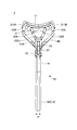
- FIG. 4A is a front view of the eyelash curler 1 of the first embodiment
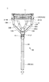
- FIG. 4B is a rear view of the eyelash curler 1 of the first embodiment.
- a direction orthogonal to the direction in which force member 20 rotates is defined as a depth direction
- at least a part of arm (first arm portion) 14 and first Of the handle 16 in the depth direction are equal.
- the width (x1) in the depth direction of the central arm 24, which is at least a part of the second arm portions 21, 24, and the second handle 25 is equal.
- width and overlapping mean not only completely equal and completely overlapping, but also including some degree of error, including partially overlapping. I do.
- the width may be different between the straight portions 251 and 161 and the curved portions 252 and 162, and in such a case, in the depth direction, the thicker portion partially overlaps the thinner portion.
- the arm 14 extends from the branch point to the handle 16 by one, and the width (depth) and height (thickness) of the handle 16 are provided. Is the same thickness as the width and thickness of the arm 14 in the depth direction.
- the fixing member 10 the power point member 20, and the action member 30 are each integrally formed of a resin, but details of the constituent resins will be described later.
- a pin shaft which is a connecting shaft for connecting the members at the connecting portion between the power point member 20 and the acting member 30 and at the connecting portion between the fixing member 10 and the power point member 20.
- PS1 which is a connecting shaft for connecting the members at the connecting portion between the power point member 20 and the acting member 30 and at the connecting portion between the fixing member 10 and the power point member 20.
- PS2 rotatably fixed by PS2
- the material forming the pin shafts PS1 and PS1 may be any material such as resin and metal.
- pin shafts PS1 and PS2 are made of resin, all the constituent elements of the eyelash curler 1 are made of resin, and it is possible to realize completely metal-free.
- FIGS. 5A and 5B are diagrams of a metal eyelash curler of a comparative example.
- the eyelash curler 9 shown in FIGS. 5A and 5B is an example of a general metal eyelash curler.
- FIG. 5A is a front perspective view of the metal eyelash curler 9 of the comparative example
- FIG. 5B is a rear perspective view of the metal eyelash curler 9 of the comparative example.
- the fixing member 70 is bonded after the upper press portion (metal frame) 11 and the thin metal bar are separately formed.
- the power point member 80 is formed by deforming a single thin metal bar.
- the operation member 90 is bonded after a lower press portion (metal frame) 91 and a thin metal bar are separately formed.
- the lower end is twisted in a ring shape to form a handle 76, and opposes at both upper ends corresponding to the parallel columns 72 ⁇ / b> A and 72 ⁇ / b> B of the metal bar.
- a longitudinally long slit is formed in the portion.
- two thin metal rods (741, 742) are twisted in a ring shape at the lower end and are in contact with the arm 74, which is an extended portion, from the support portions 72A, 73A, 72B, 73B to a position short of the handle 76. Lined up or in close proximity.
- the upper press portion 71 and the parallel columns 72A, 72B are connected by inserting and welding a metal frame into the notch holes on the inner surfaces at the tips of the parallel columns 72A, 72B, which are metal rods.
- a handle 85 is formed by twisting the ring at the lower end, and two thin metal rods (811, 812) and (2) in the arms 81 and 84, which are extending portions from the handle 85 to the distal end. 841, 842) are in contact with each other.
- the ends of a metal bar formed by bending a single metal into a substantially V-shape are welded to the lower press portion 91, which is a metal frame, so that the link portions 92A and 92B and the lower side are joined.
- the press section 91 is connected.
- the thin metal rod is inserted into the distal end engagement hole 82 of the power point member 80.
- the upper ends of the link portions 92A and 92B are welded to the lower press portion 91 in a state where the link portions 92A and 92B are bent and formed into the shapes of the link portions 92A and 92B.
- the handles 76 and 85 forming the ring are thinner by one than the arms 74 and (81, 84) combined into two.
- the column of the cross section is thin, and the holding property is poor.
- the eyelash curler 1 of the present invention is made of resin
- the arm 14, (21, 24) of the fixing member 10 and the power point member 20 is made of a single arm, They are the same thickness.
- the cross-sectional shapes of the handles 16, 25 are made the same thickness as the arms 14, 21, 24, so that the handles 16, 25 are made thick. Can be performed, the hold property is improved, and even if force is applied, the finger does not sink into the finger and does not hurt, so that sufficient force can be applied.
- the straight portion 161 and the curved portion 162 of the first handle 16 and the straight portion 251 of the second handle 25 are curved.
- the portion 252 overlaps in the depth direction.
- a handle that overlaps in the depth direction exerts a straighter force than a handle that is twisted between a straight portion and a curved portion as in the metal configuration illustrated in FIGS. 5A and 5B. Therefore, it is easier to operate, and the force on the eyelashes is easily applied.
- the arm 74 of the fixing member 70 is composed of two metal rods 741 and 742, and the interval between the rods is widened as inclined supports 73 ⁇ / b> A and 73 ⁇ / b> B.
- the arm 81 of the power point member 80 is sandwiched, and the arm 81 is engaged with the sandwiching portion 75 by passing the pin 83. Therefore, the upper side of the fulcrum where the arm 81 is sandwiched by the sandwiching portion 75 is exposed.
- hair, tissue, cotton, or the like is applied to the fulcrum where the arm 81 is sandwiched by the sandwiching portion 75.
- the joining portion 141J exists at the upper end of the arm 21 above the support hole 15 through which the power point member 20 is inserted.
- the upper side of the fulcrum of the rotating force point member 20 is not exposed. Therefore, even if hair or the like exists nearby, the possibility of being pinched by the engaging portion between the power point member 20 and the fixing member 10 is low.
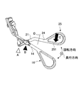
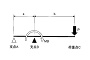
- FIGS. 6A, 6B, and 6C are diagrams for explaining how a force is applied in the eyelash curler by approximation.
- FIG. 6A is a diagram showing the positions of the fulcrum and the load point in the eyelash curler
- FIG. 6B is a diagram in which the fulcrum and the load point in FIG. 6A are projected and approximated to a simple beam (one-side concentrated load).
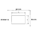
- FIG. 6C is a cross-sectional view of a beam portion of the fixing member and the power point member, and corresponds to a D section of FIG. 6A.
- the power point member 20 which is the rotating part of the eyelash curler, is restricted from rotating, and it can be considered that there is almost no rotation and movement. Therefore, the connecting part of the eyelash curler shown in FIG. , B.
- the load point C is the handle 25 of the power point member 20, and the load P is the force (grip force) applied from the finger to the eyelash curler.
- the fixing member 10 and the force-point member 20 function as “beams” of the projecting simple beam, and when considering the load and the action, as shown in FIG.
- the width (depth) (x) and height (thickness) (y) of the cross section of the beam composed of the power point member 20 are considered.
- the direction in which the force applying member 20 rotates is referred to as a rotation direction
- the direction orthogonal to the rotation direction is referred to as a depth direction
- a direction perpendicular to the depth direction in the cross section of the fixing member 10 and the power point member 20 is defined as a thickness direction.
- the cross section of the arm 14 and the handle 16 of the fixing member 10 and the arms 21, 24 and the handle 25 of the force-point member 20 to which a force is directly applied changes the thickness of the circular metal.
- the shape be a square or a rounded square.
- the configuration of the beam having a quadrangular cross section shown in FIG. 6C is an example, and the cross sectional shape of the beam of the fixing member 10 and the power point member 20 is not limited to the rectangular shape shown in FIG.
- the shape may be another shape such as a circle, an ellipse, and a semicircle.
- the present inventor evaluated the case where an external force (load P) was applied to the eyelash curler as an object by simulation based on the existing metal eyelash curler, and selected a resin. The result is shown in FIG. 8A described later.
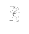
- FIGS. 7A and 7B are diagrams showing the ratio of the dimensions of the power point member. More specifically, FIG. 7A is a diagram illustrating a configuration example of the eyelash curler 1 of the present invention in which the force ratio and the movable angle of the power point member are considered, and FIG. 7B is a diagram of the eyelash curler in which the force ratio of the power point member is considered. It is a figure showing the example of composition.
- the eyelash curler 1 performs a curling operation by rotating the power point member 20 and acting on the action member 30 with the handle 25 as the power point according to the principle of the first type lever. Therefore, when the distance between the power point and the action point is farther than the distance between the fulcrum and the action point, the eyelash curling operation can be realized with a lighter force. Therefore, it is well known to design the distance a ⁇ the distance b shown in FIGS. 7A and 7B.
- the dimension of the distance a between the fulcrum B and the tip side and the distance b between the fulcrum B and the handle side of the power point member 20 influences the clamping pressure (pressure for pinching the eyelashes) by the principle of leverage.
- a: b 1: 3 or more. That is, in the power point member 20, the distance from the fulcrum to the lower end of the power point member 20 is set to be three times or more the distance from the upper end to the fulcrum.
- the distance from the fulcrum hole 23, which is the fulcrum engaged with the fixing member 10 by the pin axis PS2, to the lower end of the power point member 20 in the power point member 20, is determined by the tip that engages with the action member 30 by the pin axis PS1.
- the distance from the hole 22 to the fulcrum hole 23 is set to three times or more.
- the ratio also includes a configuration in which the power point member and the fixing member are short as shown in FIG. 7B, for example.
- the power point member 20 has such a short structure, since both the power point and the action point are close to the fulcrum B, it is necessary to apply a considerably large force to the handle and increase the movable angle at the fulcrum B. Must be set.
- the balance between the usability when pressing the straight portion 251 of the handle 25 (see FIG. 6A), which is the power point (load point), from the finger hole side and the clamp pressure sufficient to curl is generated.
- a 10 mm or more in consideration of a movable angle and a method of applying force. That is, in the first embodiment, in the power point member 20, it is preferable that the distance from the tip end hole 22 which is the upper end which is the distance from the upper end to the fulcrum B to the fulcrum hole 23 at the fulcrum B is set to 10 mm or more. is there.
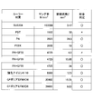
- FIG. 8A is an evaluation result when an eyelash curler is formed from a plurality of materials and used
- FIG. 8B is a diagram illustrating a feasible range based on a Young's modulus and a section modulus.
- FIG. 8A shows SUS304 (stainless steel), nylon 6/10, polyamide (PA), a material having a predetermined cross-sectional area and a cross-sectional modulus, a fiber-reinforced resin obtained by adding 55% of glass fiber (GF) to PA, It is an evaluation result when an eyelash curler having a dimension satisfying FIG. 7A is formed and used for polyetheretherketone (PEEK), polybutylene terephthalate (PBT), GF polyamide MXD6, and CF polyamide MXD6.
- PEEK polyetheretherketone
- PBT polybutylene terephthalate
- GF polyamide MXD6 GF polyamide MXD6
- PA + GF55% which is a fiber reinforced resin
- the cross-sectional area was changed and the cross-sectional coefficient was changed, and the strength was evaluated.
- the cross-sectional modulus increases, and the position on the graph of FIG. 8B moves upward, and the evaluation may be improved even with the same material.
- a material of “PA + GF55%” when the section modulus is 4.5 (mm 3 ), the strength is not satisfied, and the overall judgment is “ ⁇ ”, but when the section modulus is 15.05 (mm 3 ), and When the section modulus was 36 (mm 3 ), the strength was satisfied, and the overall judgment was “ ⁇ ”.
- a portion surrounded by a square is a recommended range set by a simulation.
- the recommended range is a material having a Young's modulus of 2500 to 40000 (N / mm 2 ) and a section modulus of 5 to 40 (mm 3 ).
- the section modulus can be reduced as the Young's modulus of the resin increases. That is, as the Young's modulus of the resin increases, the strength can be ensured even if the resin is made thinner so as to be closer to a metallic one.
- the section modulus is preferably 30 (mm 3 ) or less, and more preferably 20 (mm 3 ) or less.
- the resin has a low Young's modulus and is weak, if the section modulus is increased, the strength may be satisfied by simulation.However, in consideration of the operability, the cross section should not be too large.
- the upper limit of the coefficient was set to 40 (mm 3 ).
- the material constituting the eyelash curler is formed of a fiber-reinforced resin in which glass fiber (GF) is mixed with the resin.
- GF glass fiber
- the Young's modulus increases, and the position on the graph of FIG. 8B moves to the right.
- CF carbon fiber
- glass fiber GF or carbon fiber
- the rigidity of the resin material itself (for example, PA) against deformation and breakage of the resin material itself can be enhanced.
- a typical value of the Young's modulus is PA: 1200 to 2900 Mpa, but the Young's modulus can be increased (for example, to 4725 Mpa) by adding glass fiber.
- the resin material itself for example, PA
- the resin material itself is formed into a shape capable of suppressing the generated stress in structural analysis calculation to about 30% of the tensile strength indicating resistance to deformation and breakage. Become. Therefore, it is possible to make the eyelash curler formed of the reinforced resin close to the pressure for pinching the eyelashes of the metal eyelash curler.
- the resin mixed with the glass fiber is not particularly limited as long as the resin can be mixed with the fiber.
- the resin include polyamide (PA) (including various nylons), polyetheretherketone (PEEK), polyethylene terephthalate (PETG), glycol-modified PET (PETG), polyphenylene sulfide (PPS), polyamide MXD6, and the like. is there.
- polyamide MXD6 is a crystalline thermoplastic polymer obtained from meta-xylylenediamine (MXDA) and adipic acid.
- MXDA meta-xylylenediamine
- GF polyamide MXD6 a commercially available Reny (registered trademark) 1022H obtained by mixing 50% of glass fiber (GF) with polyamide MXD6 was used.
- CF polyamide MXD6 a commercially available RenyC408 obtained by mixing 40% of carbon fibers (CF) with polyamide MXD6 was used.
- the resin alone has a strong strength
- a special polyamide MXD6 alone and has a Young's modulus of 5000 (N / mm 2 ) or more without being reinforced with glass fiber or carbon If the strength can be compensated for by simulation, any thickness in the range of the section modulus of 5 to 40 (mm 3 ) can be adopted as the material for the eyelash curler of the present invention.
- the Young's modulus of the resin is 2500 (N / mm 2 ) or more, even if it is nylon 6/10, PEEK, PET, PETG, PPS, etc., it is within the above recommended range.
- the Young's modulus of the resin alone other than nylon 6/10 is about 2500 (N / mm 2 ) to 5000 (N / mm 2 ). If it is set slightly away from the lower end, for example, at least 10 (mm 3 ), a predetermined strength can be realized even with a single resin, and it can be used as a material for the eyelash curler of the present invention.
- the force of the user's fingers for arm 14,21,24 is stress generation range of the fixing member 10 and the force point member 20 such direct, of 2500N / mm 3 ⁇ 40000N / mm 3 in the recommended range It is preferable to satisfy Young's modulus and a section modulus of 5 mm 3 to 40 mm 3 .
- the section modulus defining the thickness may be smaller than the recommended range.
- the eyelash curler of the whole area type which is close to the entire width of the eyes, sandwiches the entire eyelashes, has been described, but the eyelash curler of the present invention having the above-described material and cross-sectional shape may be an eyelash curler for a part. .
- FIG. 9 is a configuration diagram of a partial eyelash curler according to a modification of the first embodiment of the present invention.
- the partial eyelash curler 2 has a configuration similar to that of the above-described first embodiment, and the width of the upper press portion 11P and the lower press portion 31P sandwiching the eyelashes in the depth direction is short. Therefore, the interval between the support portions 12C, 13C, 12D, and 13D of the fixing member 10P and the interval between the link portions 32C and 32D of the operation member 30P are also narrower than in the first embodiment.
- the force required to partially curl the lashes between the short width upper press portion 11P and the lower press portion 31P is greater than the force required to curl the lashes across the width of the eye. Is also small.
- the handle 16 and the handle 25 in a state where no force is applied are also set to have a small width so that the movable range of the rotation of the power point member 20P is reduced.
- the strength is ensured, and the metal is not increased in size than a general metal shape.
- the lashes can be curled by the same operation as that for the eyelashes.
- the section modulus defining the thickness may be smaller than the recommended range.
- the merging portion 141J merging with the inclined columns 13C and 13D is present. It is possible to prevent the member from being caught in the engaging portion between the member and the fixing member.
- FIG. 10 is an overall perspective view of an eyelash curler 3 according to a second embodiment of the present invention.
- FIG. 11 is an overall perspective view of the eyelash curler 3 of the second embodiment viewed from an angle different from FIG.
- FIG. 12 is an exploded view of the eyelash curler 3 of the second embodiment.
- the material and the like are the same as the resin used in the first embodiment, but the engagement (fulcrum) between the fixing member and the power point member, and the engagement between the power point member and the action member (action point). 3) is different in the hinge configuration and the like.
- a fitting groove 53 which is a fitting groove (dent) in which the lower side of the hinge is recessed is formed in the power point member 50 at a portion slightly away from the distal end.
- the supporting hole 45 formed in the arm 44 is provided with a fulcrum shaft 48 for fitting extending in the width direction (depth direction).
- FIG. 12 shows an example in which the fulcrum shaft 48 extends in the entire width direction of the support hole 45.
- the fulcrum shaft 48 that can be fitted in the fitting groove 53 is It may have a double-sided projection shape that protrudes from the inner side surface and has a broken central portion.
- the arm 44 also exists above the support hole 45, and above the support hole 15, there is a junction 441J that merges with the inclined columns 43A and 43B. Therefore, even if the fulcrum is not exposed and hair, tissue, cotton, or the like is present nearby, it is possible to prevent the fulcrum from being caught in the engaging portion between the power point member 50 and the fixing member 40.
- the operating member 60 is provided with a lower press portion 61 and link portions 62A and 62B having one end connected to the lower press portion 61.
- substantially circular (hook-shaped) engagement hooks (engagement portions) 611A and 611B are provided.
- the engaging hooks 611A and 611B are open rearward to facilitate attachment and detachment of the operating member 60 to and from the fixing member 40 during assembly.
- the other ends of the link portions 62A and 62B are bent in a U-shape to be integrally formed, and a portion that connects the other ends of the link portions 62A and 62B at the other end is a cylindrical fitting. It is a tube 63.
- the fitting tube 63 is an engaging portion of the operation member 60.
- a fitting hook 52 having a concave upper side is formed.
- the force point member 50 is pushed into the action member 60 from below, and the fitting hook 52 is engaged with the fitting cylinder 63 to connect the force point member 50 and the action member 60.
- the fitting hook 52 of the power point member 50 and the fitting tube 63 of the operating member 60 are fitted, so that the operating member 60 can move in conjunction with the operating point of the power point member 50.
- connection between the fixing member 40 and the power point member 50 (the second fulcrum B in FIG. 6A) and the connection between the power point member 50 and the operating member 60 (the first fulcrum A in FIG.
- attachment and detachment can be performed without using a shaft portion that penetrates components for connection.
- the engaged state can be released by applying a force in the direction in which the hook comes off, disassembly and assembly can be realized by the user's hand.
- the eyelash curler 3 is contaminated, it is possible to disassemble and clean, so that it is possible to clean even small irregularities of the engaging portion, and then it is possible to assemble, so that it is possible to keep cleanness in detail. it can.
- the hook can be released to prevent destruction.
- the first fulcrum A (see FIG. 6A) and the second fulcrum B are in opposite directions of engagement, so that when a strong force is applied in one direction, the first fulcrum A and the second fulcrum A Since the engagement state of only one of the fulcrums B is released, if the engagement state is suddenly detached, it can be easily restored.
- a fitting hook 52 having a concave upper side is provided at the distal end of the distal end arm 51 of the power point member 50, and a fitting with a concave lower side is provided at a portion closer to the distal end of the handle 55 of the distal end arm 51.
- a groove 53 is formed, and the arm portions (second arm portions) 51 and 54 extend from the tip to the handle 55 by a single piece.
- the portions of the handles 46 and 55 are thickened to the same thickness as the extending portions (arm portions 44, 51 and 54). Therefore, the holdability can be improved as compared with the case of metal.
- the distance from the fitting groove 53, which is a fulcrum, which engages with the fixing member 40, to the lower end of the power point member 50 is the upper end so as to satisfy the ratio of FIG. 6A.
- the distance is set to be three times or more the distance from the fitting hook 52 engaging with the action member 60 to the fitting groove 53.
- the distance from the fitting hook 52 at the upper end to the fitting groove 53 serving as a fulcrum is set to 10 mm or more so as to secure the moving amount of the lower press portion 31 of 4 mm or more.
- the undulations 541 and 542 improve the fit.
- a thumb is put in the finger hole of the handle 46 on the fixing member 40 side, and another finger is put in a finger hole of the handle 55 on the power point member 50 side.
- the middle finger into which the force is most likely to enter, is inserted into the finger hole of the handle 55, or when the ring finger is inserted into the finger hole, the wavy irregularities 541, 542 will support the force member 50 even with the index finger or the middle finger. Operation becomes stable.
- a finger hook also referred to as finger rest or finger rest
- the middle finger is inserted into the finger hole of the handle 55 on the power point member 50 side
- the ring finger is inserted into the finger holder 56, or the handle 55 of the handle 55 on the power point member 50 side is inserted.
- the index finger is put in the finger hole
- the middle finger is put in the finger hook part 56
- the ring finger is put in the finger hole of the handle 55 on the power point member 50 side
- the little finger is put in the finger hook part 56.
- the eyelashes are curled in order to support the emphasis member 50 with the wavy irregularities 541 and 542 and the finger hook portion 56, except for the finger put in the finger hole of the handle 55.
- the burden on one finger at the time of pushing is shared, and the operation is stabilized.
- hit points 47 and 57 are provided in portions facing each other when the handle 46 of the fixing member 40 and the handle 55 of the power point member 50 are closed.
- the rotation is regulated by providing the hit points 47 and 57 on the inner inner edges of the handles 46 and 55, for example, when the clipper rubber (not shown) is crushed and thinned by repeated use, it is pushed in. In this case, there is a possibility that the clamping pressure of the press section becomes insufficient. Therefore, when setting the hit points 47 and 57, it is preferable to set the length and the like including the case where the clipper rubber is crushed.
- 13A and 13B are a front view and a rear view of the eyelash curler 3 according to the second embodiment.
- a direction orthogonal to the direction in which force point member 50 rotates is defined as a depth direction
- at least a part of arm (first arm portion) 44 and a handle in fixing member 40 are provided. 46 have the same width (x2) in the depth direction. Further, in the power point member 50, it can be seen that the width (x2) in the depth direction of at least a part of the second arm portions 51 and 54 and the handle 55 is equal.
- the thickness (height) of the beams of the arms 44, 51 and 54 and the handles 46 and 55 in the rotation direction is provided. And the width is not uniform.
- the center line CL in the depth direction (direction of width x2) of the arms 44, 51, 54 extends in the same direction as the center line CL of the handles 46, 55 and overlaps. Therefore, at the time of operation, a force for pinching from the fingers is applied straight from the handles 46, 55 via the arms 44, 51, 54 extending on the same center line, so that the force for pinching the eyelashes is easily transmitted.
- the handle 46 branches from the lower end of one arm 44 at the branch point BP1 in the thickness direction, and straightens from the arm 44.
- the finger hole is formed by a straight portion 461 extending to the right and a curved portion 462 that bulges from the lower end of the straight portion 461 in the first thickness direction and turns back to return to the branch point BP1.
- the handle 55 branches off from the lower end of one of the arms 51, 54 at a branch point in the thickness direction, and extends straight from the central arm 54, which is a part of the arms 51, 54.
- a finger hole is formed by a straight portion 551 extending to the right and a curved portion 552 that bulges from a lower end of the straight portion 551 in a second thickness direction opposite to the first thickness direction, returns and returns to a branch point. It is configured to be.
- the finger holes formed in the handles 46 and 55 are substantially semicircular.
- the straight portion 461 and the curved portion 462 of the handle 46 of the fixing member 40 and the straight portion 551 and the curved portion 552 of the handle 55 of the power point member 50 overlap in the depth direction. .
- the same stress can be realized by the same bending and clamping pressure as those made of metal. Therefore, while improving the holding property of the handle, the strength can be secured without increasing the size of the metal shape, and the same eyelash curl effect as that of the metal can be exhibited by the same operation as that of the metal.
- the wavy irregularities 541 and 542 and the hit points 47 and 57 are formed.
- a wavy shape or a hit point may be applied to the first embodiment in which the pin shape engages.
- the wavy irregularities 541 and 542 and the hit points 47 and 57 may not be provided.
- the beams of the arms 14, 21, 24 and the handles 16, 25 have a width as in the first embodiment.
- the thickness may be configured to be equal.
- a handle having a substantially tear-shaped finger hole is described, and in the second embodiment, a substantially semi-circular finger hole is formed or the handle is described.
- the shape of the finger hole is reversed. Or a circular or elliptical shape.
- the handle may have a shape in which the vicinity of the branch point of the curved portion is interrupted.
Landscapes
- Hair Curling (AREA)
Abstract
Description
上側プレス部が一体的に形成された固定部材と、
下側プレス部が前記上側プレス部に対して、上下に移動可能である作用部材と、
前記固定部材と係合する部分を支点として回動することで、前記作用部材を上下に移動させる力点部材と、を有しており、
前記固定部材、前記作用部材、及び前記力点部材は、それぞれ樹脂で一体的に構成される
アイラッシュカーラー、を提供する。
図1は、本発明の第1実施形態のアイラッシュカーラーの全体斜視図である。図2は、図1とは異なる方向からみた、第1実施形態のアイラッシュカーラーの全体斜視図である。図3は、図1のアイラッシュカーラーの分解図である。
図5A,図5Bは、比較例の金属製のアイラッシュカーラーの図である。図5A,図5Bに示すアイラッシュカーラー9は、一般的な金属製のアイラッシュカーラーの一例である。図5Aは比較例の金属製のアイラッシュカーラー9の前面斜視図であり、図5Bは比較例の金属製のアイラッシュカーラー9の背面斜視図である。
アイラッシュカーラーは複雑な形状であるので、単純な形状に置き換えて形状算出を行った。
図8Aは複数の素材で、アイラッシュカーラーを形成して使用した際の評価結果であり、図8Bは、ヤング率と断面係数に基づく実施可能範囲を示す図である。
上記実施形態では、目の幅全域に近い、まつ毛全体を挟む、全域タイプのアイラッシュカーラーを前提として説明したが、本発明の上記素材及び断面形状を有するアイラッシュカーラーは、部分用のアイラッシュカーラーであってもよい。
図10は、本発明の第2実施形態のアイラッシュカーラー3の全体斜視図である。図11は、図10とは異なる角度からみた第2実施形態のアイラッシュカーラー3の全体斜視図である。図12は、第2実施形態のアイラッシュカーラー3の分解図である。
2 部分用アイラッシュカーラー
10 固定部材
11 上側プレス部
12A,12B 平行支柱(支柱部)
13A,13B 傾斜支柱(支柱部)
14 アーム(第1のアーム部)
141J 合流部
15 支持穴部
151A,151B 小孔
16 持ち手
20 力点部材
21 先端側アーム(アーム部、第2のアーム部)
22 先端孔(先端係合孔)
23 支点孔
24 中央アーム(アーム部、第2のアーム部)
25 持ち手
30 作用部材
31 下側プレス部(当接部材、上挟圧片)
311A,311B 係合フック(係合部、両端フック)
32A,32B リンク部
33 連結部
331A,331A 小孔
400 固定部材
41 上側プレス部
42A,42B 平行支柱(支柱部)
43A,43B 傾斜支柱(支柱部)
44 アーム(第1のアーム部)
441J 合流部
45 支持穴部
46 持ち手
47 ヒットポイント
48 支点軸
50 力点部材
51 先端側アーム(アーム部、第2のアーム部)
52 嵌合用フック(連結部)
53 嵌合溝(嵌合部、連結部)
54 中央アーム(アーム部、第2のアーム部)
541,542 波打ち凹凸形状
55 持ち手
56 指掛け部
57 ヒットポイント
60 作用部材
61 下側プレス部(当接部材、上挟圧片)
611A,611B 係合フック(係合部、後方フック)
62A,62B リンク部
63 連結部 A 第1の支点
B 第2の支点
C 荷重点
PS1 ピン軸
PS2 ピン軸
Claims (14)
- 上側プレス部が一体的に形成された固定部材と、
下側プレス部が前記上側プレス部に対して、上下に移動可能である作用部材と、
前記固定部材と係合する部分を支点として回動することで、前記作用部材を上下に移動させる力点部材と、を有しており、
前記固定部材、前記作用部材、及び前記力点部材は、それぞれ樹脂で一体的に構成される
アイラッシュカーラー。 - 前記固定部材は、前記上側プレス部と、使用者が指を掛ける第1の持ち手と、上下方向に延伸する第1のアーム部と、該第1のアーム部から2つに分岐して前記上側プレス部の両端部を支持する一対の支柱と、が一体的に形成され、
前記力点部材は、前記使用者が指を掛ける第2の持ち手と、延伸する第2のアーム部と、が一体的に形成され、
前記第1のアーム部には、前記力点部材が挿通する支持穴部が形成されている
請求項1に記載のアイラッシュカーラー。 - 前記力点部材が回動する方向と直交する方向を奥行方向としたとき、
前記第1のアーム部の少なくとも一部と、前記第1の持ち手の、前記奥行方向における幅が等しく、
前記第2のアーム部の少なくとも一部と、前記第2の持ち手の、前記奥行方向における幅が等しい
請求項2に記載のアイラッシュカーラー。 - 前記固定部材および前記力点部材の断面において前記奥行方向と直交する方向を厚さ方向とするとき、
前記固定部材おいて、前記第1の持ち手は、1本の前記第1のアーム部の下端から厚さ方向に分岐点で分岐して、前記第1のアーム部から直線状に延伸する直線部と、該直線部の下端から第1の厚さ方向に膨らんで折り返して前記分岐点に戻る湾曲部からなるリングで形成され、
前記力点部材において、前記第2の持ち手は、1本の前記第2のアーム部の下端から厚さ方向に分岐点で分岐して、前記第2のアーム部から直線状に延伸する直線部と、該直線部の下端から前記第1の厚さ方向とは反対方向の第2の厚さ方向に膨らんで折り返して前記分岐点に戻る湾曲部からなるリングで形成され、
前記第1の持ち手の前記直線部と前記湾曲部と、前記第2の持ち手の前記直線部と前記湾曲部は、前記奥行方向において重なっている
請求項3に記載のアイラッシュカーラー。 - 前記力点部材の、前記支点となる部分には、前記力点部材が回動する方向と直交する奥行方向に貫通する支点孔が形成され、
前記固定部材の前記第1のアーム部の前記支持穴部の両側壁には、小孔が形成され、
前記力点部材の前記第2のアーム部が、上端部から、前記固定部材の前記支持穴部に挿入された状態で、前記支点孔と、前記両側壁の小孔とを貫通するように、ピン軸で係止され、前記ピン軸が前記固定部材の回動の支点となる
請求項2乃至4のいずれか一項に記載のアイラッシュカーラー。 - 前記作用部材は、前記下側プレス部と、上端が該下側プレス部と連結するリンク部と、前記リンク部の下端と連結する連結部が、一体的に形成されており、
前記力点部材の上端部には、前記力点部材が回動する方向と直交する奥行方向に貫通する先端孔が形成され
前記連結部は下端に対してU字状に凹んでおり、凹みの両側面には小孔が形成され、
前記力点部材の前記第2のアーム部の上端が、前記連結部の前記凹みの内側に挿入され、先端孔と、前記連結部の前記両側面の小孔を貫通するように、ピン軸で係止されることで、
前記作用部材が前記力点部材と連動して移動可能に、連結する
請求項2乃至5のいずれか一項に記載のアイラッシュカーラー。 - 前記作用部材において、前記下側プレス部の左右の両端は、前記奥行方向に両側が開口したフック形状の両端フックとなっており、
前記両端フックと、前記一対の支柱に対して嵌合することで、前記作用部材は、前記固定部材に対してスライド可能になる
請求項6に記載のアイラッシュカーラー。 - 前記力点部材において、下側が凹んだ嵌合用の窪みが形成され、
前記固定部材において、前記支持穴部の内部に、嵌合突起が設けられ、
前記力点部材の嵌合用の窪みと、前記固定部材の前記嵌合突起とが嵌合した嵌合部を支点として、前記力点部材が前記固定部材に対して回動自在に連結することで、回動による力が上方向に作用するように前記作用部材に伝達する
請求項2乃至4のいずれか一項に記載のアイラッシュカーラー。 - 前記作用部材は、前記下側プレス部と、一端が該下側プレス部と連結するリンク部とが一体的に形成されており、
前記力点部材の上端には、上側が凹んだ嵌合用フックが形成され、
前記作用部材の前記リンク部の他端には、嵌合筒が設けられ
前記力点部材の嵌合用フックと、前記作用部材の前記嵌合筒とが嵌合することで、前記作用部材が前記力点部材とが連動して移動可能に、連結する
請求項8に記載のアイラッシュカーラー。 - 前記作用部材において、前記下側プレス部の左右の両端は、後方に開口したフック形状の後方フックとなっており、
前記後方フックが、前記一対の支柱に対して嵌合することで、前記作用部材は、前記固定部材に対してスライド可能になる
請求項9に記載のアイラッシュカーラー。 - 前記樹脂は、ヤング率が2500N/mm3~40000N/mm3の素材であり、前記固定部材の前記第1のアーム部と前記力点部材の前記第2のアーム部は、断面係数が5mm3~40mm3で構成される
請求項2乃至10のいずれか一項に記載のアイラッシュカーラー。 - 前記樹脂は、ポリアミド(PA)、ポリエーテルエーテルケトン(PEEK)、ポリエチレンテレフタレート(PET)、グリコール変性PET(PETG)、ポリフェニレンサルファイド(PPS)、ポリアミドMXD6のいずれかの樹脂に、ガラス繊維(GF)を配合することで構成される繊維強化樹脂である
請求項11に記載のアイラッシュカーラー。 - 前記繊維強化樹脂は、前記ガラス繊維(GF)を、30質量%以上、65質量%以下、前記樹脂に配合することで構成される
請求項12に記載のアイラッシュカーラー。 - 前記樹脂は、ナイロン6/10、ポリエーテルエーテルケトン(PEEK)、ポリエチレンテレフタレート(PET)、グリコール変性PET(PETG)、ポリフェニレンサルファイド(PPS)、ポリアミドMXD6のいずれかであり、
前記固定部材の前記第1のアーム部と前記力点部材の前記第2のアーム部は、断面係数を10mm3以上にする
請求項11に記載のアイラッシュカーラー。
Priority Applications (3)
| Application Number | Priority Date | Filing Date | Title |
|---|---|---|---|
| JP2020548495A JP7577540B2 (ja) | 2018-09-18 | 2019-09-17 | アイラッシュカーラー |
| CN201980061178.8A CN112822957B (zh) | 2018-09-18 | 2019-09-17 | 睫毛夹 |
| JP2023135631A JP7740787B2 (ja) | 2018-09-18 | 2023-08-23 | アイラッシュカーラー |
Applications Claiming Priority (2)
| Application Number | Priority Date | Filing Date | Title |
|---|---|---|---|
| JP2018-174220 | 2018-09-18 | ||
| JP2018174220 | 2018-09-18 |
Publications (1)
| Publication Number | Publication Date |
|---|---|
| WO2020059690A1 true WO2020059690A1 (ja) | 2020-03-26 |
Family
ID=69887119
Family Applications (1)
| Application Number | Title | Priority Date | Filing Date |
|---|---|---|---|
| PCT/JP2019/036322 Ceased WO2020059690A1 (ja) | 2018-09-18 | 2019-09-17 | アイラッシュカーラー |
Country Status (4)
| Country | Link |
|---|---|
| JP (2) | JP7577540B2 (ja) |
| CN (1) | CN112822957B (ja) |
| TW (1) | TW202019317A (ja) |
| WO (1) | WO2020059690A1 (ja) |
Citations (6)
| Publication number | Priority date | Publication date | Assignee | Title |
|---|---|---|---|---|
| JPH0513301U (ja) * | 1991-08-02 | 1993-02-23 | 株式会社貝印刃物開発センター | まつ毛カーラーにおけるまつ毛挾持構造 |
| JP2001070030A (ja) * | 1999-09-08 | 2001-03-21 | Shishida Seishindo:Kk | ビューラ |
| JP2001509035A (ja) * | 1995-08-18 | 2001-07-10 | マクマレン,アレクサンドラ | 熱保持性を高めるよう適合された遠隔加熱まつげカール装置 |
| JP2004275222A (ja) * | 2003-03-12 | 2004-10-07 | Kaijirushi Hamono Kaihatsu Center:Kk | 下まつ毛用まつ毛カール器 |
| JP2005058424A (ja) * | 2003-08-11 | 2005-03-10 | Kunio Kamishige | まつ毛カール器 |
| JP2007300971A (ja) * | 2006-05-08 | 2007-11-22 | ▲張▼海燕 | まつげカーラー |
Family Cites Families (10)
| Publication number | Priority date | Publication date | Assignee | Title |
|---|---|---|---|---|
| JPS5758302U (ja) * | 1980-09-26 | 1982-04-06 | ||
| JPH04221516A (ja) * | 1990-12-25 | 1992-08-12 | Keisuke Kotake | 枕 |
| JP2002000335A (ja) * | 2000-06-16 | 2002-01-08 | Tescom:Kk | まつげ手入れ用具 |
| JP3965339B2 (ja) | 2002-09-03 | 2007-08-29 | 英行 野尻 | まつげカーラー |
| KR100893362B1 (ko) * | 2007-10-24 | 2009-04-17 | 홍익대학교 산학협력단 | 속눈썹 뷰러 |
| CN102283486A (zh) | 2010-06-21 | 2011-12-21 | 潘三候 | 一种睫毛夹 |
| JP6639765B2 (ja) | 2013-05-01 | 2020-02-05 | ロレアル | 睫毛をカーリングするためのアイラッシュカーラー |
| US9724181B2 (en) * | 2014-05-07 | 2017-08-08 | Braun Gmbh | Oral care implement |
| CN205214528U (zh) | 2015-12-16 | 2016-05-11 | 永嘉县罗浮美容工具厂 | 一种睫毛卷曲夹 |
| JP6897057B2 (ja) * | 2016-10-21 | 2021-06-30 | 富士フイルムビジネスイノベーション株式会社 | 樹脂組成物、及び樹脂成形体 |
-
2019
- 2019-09-17 WO PCT/JP2019/036322 patent/WO2020059690A1/ja not_active Ceased
- 2019-09-17 JP JP2020548495A patent/JP7577540B2/ja active Active
- 2019-09-17 CN CN201980061178.8A patent/CN112822957B/zh active Active
- 2019-09-18 TW TW108133561A patent/TW202019317A/zh unknown
-
2023
- 2023-08-23 JP JP2023135631A patent/JP7740787B2/ja active Active
Patent Citations (6)
| Publication number | Priority date | Publication date | Assignee | Title |
|---|---|---|---|---|
| JPH0513301U (ja) * | 1991-08-02 | 1993-02-23 | 株式会社貝印刃物開発センター | まつ毛カーラーにおけるまつ毛挾持構造 |
| JP2001509035A (ja) * | 1995-08-18 | 2001-07-10 | マクマレン,アレクサンドラ | 熱保持性を高めるよう適合された遠隔加熱まつげカール装置 |
| JP2001070030A (ja) * | 1999-09-08 | 2001-03-21 | Shishida Seishindo:Kk | ビューラ |
| JP2004275222A (ja) * | 2003-03-12 | 2004-10-07 | Kaijirushi Hamono Kaihatsu Center:Kk | 下まつ毛用まつ毛カール器 |
| JP2005058424A (ja) * | 2003-08-11 | 2005-03-10 | Kunio Kamishige | まつ毛カール器 |
| JP2007300971A (ja) * | 2006-05-08 | 2007-11-22 | ▲張▼海燕 | まつげカーラー |
Also Published As
| Publication number | Publication date |
|---|---|
| JP2023162309A (ja) | 2023-11-08 |
| CN112822957B (zh) | 2025-01-17 |
| JP7740787B2 (ja) | 2025-09-17 |
| JP7577540B2 (ja) | 2024-11-05 |
| TW202019317A (zh) | 2020-06-01 |
| CN112822957A (zh) | 2021-05-18 |
| JPWO2020059690A1 (ja) | 2021-08-30 |
Similar Documents
| Publication | Publication Date | Title |
|---|---|---|
| TW200906332A (en) | Eyelash curler | |
| JP2021180792A (ja) | 薬剤塗布具、薬剤塗布用キットおよび薬剤塗布具用押圧具 | |
| CA2851017C (en) | A chair with a pivoting backrest | |
| CN107249368B (zh) | 假发用固接件以及使用该假发用固接件的假发 | |
| US20140114332A1 (en) | Surgical clip | |
| WO2019163569A1 (ja) | 理髪用鋏 | |
| TW561032B (en) | Nail clippers | |
| CN104918758B (zh) | 美容美发剪刀 | |
| JP7740787B2 (ja) | アイラッシュカーラー | |
| JP4889701B2 (ja) | 理美容はさみ | |
| KR101489120B1 (ko) | 바이스 그립 플라이어 | |
| WO2020059714A1 (ja) | 化粧道具およびアイラッシュカーラー | |
| JP6695488B1 (ja) | 毛抜き具 | |
| JP2004057580A (ja) | まつ毛カール器 | |
| JP4156601B2 (ja) | 睫毛カール器 | |
| KR200481334Y1 (ko) | 헤어클립 | |
| CN205214529U (zh) | 睫毛卷曲夹 | |
| JP2020130824A (ja) | ニッパー式爪切り | |
| KR102633216B1 (ko) | 발열기능을 갖는 속눈썹 성형부재 및 이를 포함하는 속눈썹 컬링장치 | |
| JP2020092939A (ja) | アイラッシュカーラー | |
| JP2012040036A (ja) | 睫毛カール器 | |
| KR20250151871A (ko) | 이미용 가위 | |
| JP3088991U (ja) | 下まつげ用カール器 | |
| MXPA06012704A (es) | Pinzas para uso cosmetico. | |
| KR101842671B1 (ko) | 눈썹 문신 그리기용 보조 용구 |
Legal Events
| Date | Code | Title | Description |
|---|---|---|---|
| 121 | Ep: the epo has been informed by wipo that ep was designated in this application |
Ref document number: 19863921 Country of ref document: EP Kind code of ref document: A1 |
|
| ENP | Entry into the national phase |
Ref document number: 2020548495 Country of ref document: JP Kind code of ref document: A |
|
| NENP | Non-entry into the national phase |
Ref country code: DE |
|
| 122 | Ep: pct application non-entry in european phase |
Ref document number: 19863921 Country of ref document: EP Kind code of ref document: A1 |
|
| WWG | Wipo information: grant in national office |
Ref document number: 201980061178.8 Country of ref document: CN |