WO2020054220A1 - 修理パッチ、修理パッチの成形方法及び複合材の修理方法 - Google Patents
修理パッチ、修理パッチの成形方法及び複合材の修理方法 Download PDFInfo
- Publication number
- WO2020054220A1 WO2020054220A1 PCT/JP2019/028830 JP2019028830W WO2020054220A1 WO 2020054220 A1 WO2020054220 A1 WO 2020054220A1 JP 2019028830 W JP2019028830 W JP 2019028830W WO 2020054220 A1 WO2020054220 A1 WO 2020054220A1
- Authority
- WO
- WIPO (PCT)
- Prior art keywords
- patch
- repair
- removal layer
- repaired
- laminate
- Prior art date
- Legal status (The legal status is an assumption and is not a legal conclusion. Google has not performed a legal analysis and makes no representation as to the accuracy of the status listed.)
- Ceased
Links
Images


Classifications
-
- B—PERFORMING OPERATIONS; TRANSPORTING
- B29—WORKING OF PLASTICS; WORKING OF SUBSTANCES IN A PLASTIC STATE IN GENERAL
- B29C—SHAPING OR JOINING OF PLASTICS; SHAPING OF MATERIAL IN A PLASTIC STATE, NOT OTHERWISE PROVIDED FOR; AFTER-TREATMENT OF THE SHAPED PRODUCTS, e.g. REPAIRING
- B29C73/00—Repairing of articles made from plastics or substances in a plastic state, e.g. of articles shaped or produced by using techniques covered by this subclass or subclass B29D
- B29C73/04—Repairing of articles made from plastics or substances in a plastic state, e.g. of articles shaped or produced by using techniques covered by this subclass or subclass B29D using preformed elements
- B29C73/10—Repairing of articles made from plastics or substances in a plastic state, e.g. of articles shaped or produced by using techniques covered by this subclass or subclass B29D using preformed elements using patches sealing on the surface of the article
-
- B—PERFORMING OPERATIONS; TRANSPORTING
- B29—WORKING OF PLASTICS; WORKING OF SUBSTANCES IN A PLASTIC STATE IN GENERAL
- B29C—SHAPING OR JOINING OF PLASTICS; SHAPING OF MATERIAL IN A PLASTIC STATE, NOT OTHERWISE PROVIDED FOR; AFTER-TREATMENT OF THE SHAPED PRODUCTS, e.g. REPAIRING
- B29C70/00—Shaping composites, i.e. plastics material comprising reinforcements, fillers or preformed parts, e.g. inserts
- B29C70/04—Shaping composites, i.e. plastics material comprising reinforcements, fillers or preformed parts, e.g. inserts comprising reinforcements only, e.g. self-reinforcing plastics
- B29C70/28—Shaping operations therefor
- B29C70/30—Shaping by lay-up, i.e. applying fibres, tape or broadsheet on a mould, former or core; Shaping by spray-up, i.e. spraying of fibres on a mould, former or core
-
- B—PERFORMING OPERATIONS; TRANSPORTING
- B29—WORKING OF PLASTICS; WORKING OF SUBSTANCES IN A PLASTIC STATE IN GENERAL
- B29C—SHAPING OR JOINING OF PLASTICS; SHAPING OF MATERIAL IN A PLASTIC STATE, NOT OTHERWISE PROVIDED FOR; AFTER-TREATMENT OF THE SHAPED PRODUCTS, e.g. REPAIRING
- B29C70/00—Shaping composites, i.e. plastics material comprising reinforcements, fillers or preformed parts, e.g. inserts
- B29C70/04—Shaping composites, i.e. plastics material comprising reinforcements, fillers or preformed parts, e.g. inserts comprising reinforcements only, e.g. self-reinforcing plastics
- B29C70/28—Shaping operations therefor
- B29C70/54—Component parts, details or accessories; Auxiliary operations, e.g. feeding or storage of prepregs or SMC after impregnation or during ageing
- B29C70/542—Placing or positioning the reinforcement in a covering or packaging element before or during moulding, e.g. drawing in a sleeve
-
- B—PERFORMING OPERATIONS; TRANSPORTING
- B29—WORKING OF PLASTICS; WORKING OF SUBSTANCES IN A PLASTIC STATE IN GENERAL
- B29C—SHAPING OR JOINING OF PLASTICS; SHAPING OF MATERIAL IN A PLASTIC STATE, NOT OTHERWISE PROVIDED FOR; AFTER-TREATMENT OF THE SHAPED PRODUCTS, e.g. REPAIRING
- B29C73/00—Repairing of articles made from plastics or substances in a plastic state, e.g. of articles shaped or produced by using techniques covered by this subclass or subclass B29D
- B29C73/04—Repairing of articles made from plastics or substances in a plastic state, e.g. of articles shaped or produced by using techniques covered by this subclass or subclass B29D using preformed elements
- B29C73/14—Repairing of articles made from plastics or substances in a plastic state, e.g. of articles shaped or produced by using techniques covered by this subclass or subclass B29D using preformed elements using elements composed of two parts joined together after having been placed one on each side of the article
-
- B—PERFORMING OPERATIONS; TRANSPORTING
- B29—WORKING OF PLASTICS; WORKING OF SUBSTANCES IN A PLASTIC STATE IN GENERAL
- B29C—SHAPING OR JOINING OF PLASTICS; SHAPING OF MATERIAL IN A PLASTIC STATE, NOT OTHERWISE PROVIDED FOR; AFTER-TREATMENT OF THE SHAPED PRODUCTS, e.g. REPAIRING
- B29C2793/00—Shaping techniques involving a cutting or machining operation
- B29C2793/0036—Slitting
-
- B—PERFORMING OPERATIONS; TRANSPORTING
- B32—LAYERED PRODUCTS
- B32B—LAYERED PRODUCTS, i.e. PRODUCTS BUILT-UP OF STRATA OF FLAT OR NON-FLAT, e.g. CELLULAR OR HONEYCOMB, FORM
- B32B17/00—Layered products essentially comprising sheet glass, or glass, slag, or like fibres
- B32B17/02—Layered products essentially comprising sheet glass, or glass, slag, or like fibres in the form of fibres or filaments
- B32B17/04—Layered products essentially comprising sheet glass, or glass, slag, or like fibres in the form of fibres or filaments bonded with or embedded in a plastic substance
-
- B—PERFORMING OPERATIONS; TRANSPORTING
- B32—LAYERED PRODUCTS
- B32B—LAYERED PRODUCTS, i.e. PRODUCTS BUILT-UP OF STRATA OF FLAT OR NON-FLAT, e.g. CELLULAR OR HONEYCOMB, FORM
- B32B2260/00—Layered product comprising an impregnated, embedded, or bonded layer wherein the layer comprises an impregnation, embedding, or binder material
- B32B2260/02—Composition of the impregnated, bonded or embedded layer
- B32B2260/021—Fibrous or filamentary layer
- B32B2260/023—Two or more layers
-
- B—PERFORMING OPERATIONS; TRANSPORTING
- B32—LAYERED PRODUCTS
- B32B—LAYERED PRODUCTS, i.e. PRODUCTS BUILT-UP OF STRATA OF FLAT OR NON-FLAT, e.g. CELLULAR OR HONEYCOMB, FORM
- B32B2556/00—Patches, e.g. medical patches, repair patches
-
- B—PERFORMING OPERATIONS; TRANSPORTING
- B64—AIRCRAFT; AVIATION; COSMONAUTICS
- B64F—GROUND OR AIRCRAFT-CARRIER-DECK INSTALLATIONS SPECIALLY ADAPTED FOR USE IN CONNECTION WITH AIRCRAFT; DESIGNING, MANUFACTURING, ASSEMBLING, CLEANING, MAINTAINING OR REPAIRING AIRCRAFT, NOT OTHERWISE PROVIDED FOR; HANDLING, TRANSPORTING, TESTING OR INSPECTING AIRCRAFT COMPONENTS, NOT OTHERWISE PROVIDED FOR
- B64F5/00—Designing, manufacturing, assembling, cleaning, maintaining or repairing aircraft, not otherwise provided for; Handling, transporting, testing or inspecting aircraft components, not otherwise provided for
- B64F5/40—Maintaining or repairing aircraft
-
- Y—GENERAL TAGGING OF NEW TECHNOLOGICAL DEVELOPMENTS; GENERAL TAGGING OF CROSS-SECTIONAL TECHNOLOGIES SPANNING OVER SEVERAL SECTIONS OF THE IPC; TECHNICAL SUBJECTS COVERED BY FORMER USPC CROSS-REFERENCE ART COLLECTIONS [XRACs] AND DIGESTS
- Y10—TECHNICAL SUBJECTS COVERED BY FORMER USPC
- Y10T—TECHNICAL SUBJECTS COVERED BY FORMER US CLASSIFICATION
- Y10T428/00—Stock material or miscellaneous articles
- Y10T428/14—Layer or component removable to expose adhesive
Definitions
- the present invention relates to a repair patch for a composite material for repairing a part to be repaired of the composite material, a method for forming the repair patch, and a method for repairing the composite material.
- a repair patch as disclosed in Patent Document 1.
- the repair patch has a truncated cone shape and has a bottom surface, a top surface, and an inclined surface.
- the repair patch having a truncated cone shape is formed by concentrically laminating circular reinforcing fiber substrates having different diameters.
- the repair patch of the present invention is a repair patch of a composite material for repairing a repaired portion to be repaired of the composite material, wherein the repair patch is formed by laminating a plurality of reinforcing fiber base materials in the thickness direction and adhered to the repaired portion.
- a patch body having an adhesive surface, and a removal layer provided on the adhesive surface and peelable from the patch body, wherein the adhesive surface is inclined with respect to the thickness direction of the patch body.
- the removal layer has a portion to be processed for forming a shape complementary to the inclined surface of the patch body.
- the end portions of the plurality of reinforcing fiber bases that form the inclined surface of the patch body can be pressed by the removal layer having a shape complementary to the inclined surface.
- the occurrence of fiber meandering can be suppressed.
- the shape of the patch main body can be made an appropriate shape.
- the adhesive layer of the patch body can be protected by the removal layer.
- the end of the reinforcing fiber base can be appropriately held down by the removal layer.
- the processed portion is a plurality of through holes formed at positions facing the thickness direction of the patch main body with respect to ends of the plurality of reinforcing fiber bases on the inclined surface. Is preferred.
- the end portion of the reinforcing fiber base can be appropriately held down by the removal layer.
- the removal layer is a peel ply.
- the adhesive surface of the patch body can be activated, so that the adhesiveness to the part to be repaired can be enhanced.
- the method of forming a repair patch of the present invention is a method of forming a repair patch of a composite material that repairs a repair target portion to be repaired of a composite material, such that an adhesive surface adhered to the repair target portion is an upper surface.
- the removal layer is provided with a portion to be processed to have a shape complementary to the inclined surface of the laminate, and in the molding step, the removal layer is formed by the portion to be processed by the portion to be processed. It is characterized by being deformed following the shape of the inclined surface.
- a covering member that follows the deformation of the removal layer is disposed so as to cover the removal layer, and the laminate and the removal layer are formed.
- the covering member may be a bag film having good followability, or may be a film adhesive provided between the bag film and the removal layer, and is not particularly limited.
- the repair patch is prepared in advance, and the removal layer is peeled from the patch body.
- the patch main body by removing the removal layer from the patch main body, the protected adhesive surface of the patch main body is exposed, and the patch main body can be bonded to the portion to be repaired. For this reason, the patch main body having an appropriate shape can be adhered to the repaired portion while suppressing adhesion of foreign matter to the adhesive surface, and thus the repaired portion can be suitably repaired.
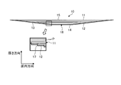
- FIG. 1 is a cross-sectional view schematically illustrating an example of a repair patch according to the first embodiment.
- FIG. 2 is a plan view showing a removal layer of the repair patch.
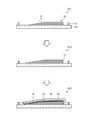
- FIG. 3 is an explanatory diagram relating to a method for forming a repair patch according to the first embodiment.
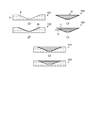
- FIG. 4 is a diagram illustrating a method for repairing a composite material using the repair patch according to the first embodiment.
- FIG. 5 is a graph related to the repair result of the repaired part repaired by the repair patch according to the first embodiment.
- FIG. 6 is a plan view illustrating a removal layer of a repair patch according to the second embodiment.
- the repair patch 10 is a repair material used when repairing a composite material.
- the method of repairing a composite material using the repair patch 10 is for repairing a defective portion formed on the composite material due to damage or the like, and repairing the repaired portion to be repaired.
- FIG. 1 is a cross-sectional view schematically illustrating an example of the repair patch according to the first embodiment.
- FIG. 2 is a plan view showing a removal layer of the repair patch.
- FIG. 3 is an explanatory diagram relating to a method for forming a repair patch according to the first embodiment.
- FIG. 3 is an explanatory diagram relating to a method for repairing a composite material using the repair patch according to the first embodiment.
- FIG. 5 is a graph related to the repair result of the repaired part repaired by the repair patch according to the first embodiment.
- the repair patch 10 is configured using a composite material, and includes a patch body 11 and a removal layer 12.
- the patch body 11 has a truncated cone shape having a bottom surface 15, a top surface 14, and a side surface (inclined surface) 13.
- the top surface 14 and the side surface 13 are an adhesive surface 18 to be adhered to the portion to be repaired, and the bottom surface 15 is a surface opposite to the adhesive surface 18.
- This patch body 11 is obtained by laminating a plurality of prepregs P as a reinforcing fiber base material in the thickness direction and temporarily curing (precuring) them. Note that a direction along a plane orthogonal to the thickness direction is an in-plane direction.
- the prepreg is obtained by impregnating a reinforcing fiber with a resin.
- the reinforcing fiber for example, carbon fiber is used, but is not limited to carbon fiber, and may be other plastic fiber, glass fiber, natural fiber or metal fiber.
- the resin is preferably a thermosetting resin, but may be a thermoplastic resin.
- the thermosetting resin is, for example, an epoxy resin.
- thermoplastic resin examples include polyether ether ketone (PEEK), polyether ketone ketone (PEKK), and polyphenylene sulfide (PPS).
- PEEK polyether ether ketone
- PEKK polyether ketone ketone
- PPS polyphenylene sulfide
- the resin is not limited to these, and other resins may be used. Further, in addition to molding using a prepreg, a method such as hand lay-up, resin infusion, RTM, or the like may be applied.
- the patch body 11 uses a plurality of prepregs P cut into a circular shape, and the plurality of prepregs P are cut into a circular shape so that the diameters thereof increase at a constant rate.
- the prepregs P are concentrically stacked with their central axes aligned in the order of size to form a patch body 11 having a truncated cone shape. For this reason, in the radial direction of the patch main body 11 having a circular shape, the interval between the outer ends of the prepregs P adjacent in the thickness direction is a predetermined concentric interval.
- the bonding surface 18 has a top surface 14 and a side surface 13.
- the bonding surfaces 18 In the cross section shown in FIG. 1 cut along the central axis of the patch main body 11 having a truncated conical shape in the thickness direction of the patch main body 11, the bonding surfaces 18 have side surfaces 13 on both sides in the in-plane direction across the top surface 14. Is located.
- Each side surface 13 is a surface inclined linearly with respect to the thickness direction. That is, in the cross section shown in FIG. 1, the side surfaces 13 on both sides are inclined with respect to the thickness direction so as to spread from the removal layer 12 toward the patch body 11.
- the bottom surface 15 is a surface extending in the in-plane direction, and is a surface serving as a surface of the repaired portion 5 after the repair.
- the removal layer 12 is provided on the adhesive surface 18 side of the patch main body 11 in the thickness direction, and is detachably joined to the patch main body 11.
- the removal layer 12 is configured using, for example, a peel ply.
- the removal layer 12 is formed with a portion to be processed to have a shape complementary to the side surface 13 of the patch body 11. Specifically, the processed part is a plurality of slits 17.
- the plurality of slits 17 are formed at positions facing the outer ends of the plurality of prepregs P in the thickness direction. For this reason, the slits 17 are formed in a circular shape, and the plurality of slits 17 are formed concentrically at predetermined intervals in the radial direction.
- the slit 17 is formed in a C-shape that is partially connected in the circumferential direction so as not to be separated when the removal layer 12 is peeled off.
- the removal layer 12 is complementary to the outer end of the step-shaped prepreg P on the side surface 13 of the patch body 11. It is shaped like a step.
- FIG. 3 shows a part of the repair patch 10.
- the stacked body 16 is formed by stacking a plurality of prepregs P in the thickness direction on the forming die 20 (Step S11: stacked body forming step).
- a circular prepreg P having a large diameter is laminated on the molding die 20, and a circular prepreg P having a smaller diameter is laminated toward the upper side.
- vacuum suction is performed each time a predetermined number of prepregs P are laminated. That is, when the prepregs P are stacked, a gap may be formed between the layers of the prepregs P to be stacked. Therefore, the gap formed between the layers of the prepreg P is removed by periodically performing vacuum suction.
- the bonding surface 18 of the laminate 16 formed on the mold 20 is the upper surface.
- the removal layer 12 is arranged so as to cover the bonding surface 18 of the laminate 16 formed on the mold 20 (step S12: removal layer arrangement step).
- the removal layer 12 is disposed on the laminate 16 such that the slit 17 of the removal layer 12 faces the outer end of each prepreg P of the laminate 16.
- Step S13 forming step.
- the film adhesive 19 is arranged so as to cover the removal layer 12.
- the film adhesive 19 is a covering member that follows the deformation of the removal layer 12 during molding, and allows the removal layer 12 to deform.
- the film adhesive 19 is, for example, a thermosetting resin that melts when heated, and at least a portion of the film adhesive 19 is impregnated in the prepreg P and is thermoset.
- a shield film 25 using a fluororesin such as FEP is arranged so as to cover the film adhesive 19. The shield film 25 prevents the resin melted during molding from flowing into a breather 26 described later.
- the breather 26 is arranged so as to cover the shield film 25.
- the breather 26 forms an air flow path during vacuum suction.
- the bag film 27 is arranged so as to cover the breather 26, and the space between the molding die 20 and the bag film 27 is sealed by the sealing member 21 so that the inside of the bag film 27 is sealed. Form a space.
- the inside of the bag film 27 is evacuated by vacuum-suctioning the closed space formed inside the bag film 27 via a vacuum suction port (not shown). Then, in the forming step S13, the repair patch 10 which is temporarily cured is formed by heating the laminate 16, the removal layer 12, and the film adhesive 19 in a vacuum state.
- the forming step S13 since the slits 17 are formed in the removal layer 12, the inside of the bag film 27 is suctioned by vacuum, so that the removal layer 12 between the slits 17 is formed by the prepreg P of the laminate 16. Is pressed in the thickness direction, and in this state, the laminate 16 and the removal layer 12 are thermally cured. For this reason, in the forming step S13, the removal layer 12 is deformed by the slit 17 following the side surface 13 of the stacked body 16 having the step shape.
- the repair patch 10 described above and the resin sheet 28 as an adhesive are used.
- the resin sheet 28 is formed by forming a resin into a sheet shape, and is made of a material that can be bonded to the resin used for the repair patch 10.
- the resin sheet 28 may be the same as or different from the resin used for the repair patch 10, and is not particularly limited.
- a plurality of types of repair patches 10 having different diameters are prepared, and the repair patches 10 are appropriately selected and used according to the shape (size) of a counterbore 6 to be described later.
- the missing portion formed in the composite material is processed by cutting or the like to form the counterbore 6 having the shape shown in FIG. 4 (step S21).
- the counterbore 6 has an opening formed in a circular shape, and a bottom surface formed in a circular shape smaller than the opening. Further, the counterbore hole 6 is a surface that is inclined so that the side surface is widened from the bottom surface toward the opening portion.
- the counterbore 6 has a bottom surface and side surfaces serving as surfaces to which the repair patch 10 is bonded.
- Step S22 adhesive disposing step. Specifically, in the adhesive disposing step S22, the resin sheet 28 is disposed so as to be in contact with the inner surfaces of the counterbore holes 6 and cover these surfaces.
- the repair patch 10 is prepared (step S23). Then, the removal layer 12 is peeled from the patch body 11 of the repair patch 10 (step S24: peeling step).
- step S25 patch arrangement step.
- marking is performed on the bottom surface (front surface) of the patch body 11 and marking is performed on the surface of the composite material to be the part 5 to be repaired.
- the patch body 11 may be arranged in the counterbore 6 so that the position is an appropriate position.
- step S26 bonding step.
- the patch body 11 and the resin sheet 28 are sealed by using a bag film or the like, and the patch body 11 and the resin sheet 28 are heated while evacuating the sealed space.
- the repair patch 10 and the resin sheet 28 are completely cured.
- the surface of the composite material to be repaired and the bottom surface 15 of the patch body 11 are subjected to a finishing process (step S26) to repair the portion to be repaired 5.
- the vertical axis indicates the breaking strain.
- a repair patch used for repairing a repaired portion has a meandering fiber at the outer end of the prepreg P. Comparing the fracture strain between the conventional and the first embodiment, it was confirmed that the fracture strain of the first embodiment was larger than the conventional one. That is, it was confirmed that the repair of the repaired portion 5 by using the repair patch 10 of the first embodiment has a greater strength recovery than the related art.
- the outer end portions of the plurality of prepregs P constituting the side surface 13 of the patch body 11 can be pressed by the removal layer 12 having a shape complementary to the side surface 13.
- the occurrence of fiber meandering at the outer end of the prepreg P can be suppressed. Therefore, the shape of the patch main body 11 can be made appropriate. Further, the adhesive layer 18 of the patch body 11 can be protected by the removal layer 12.
- the outer end of the prepreg P can be appropriately pressed by the removal layer 12.
- the adhesive surface 18 of the patch body 11 can be activated, and therefore, the adhesiveness to the counterbore 6 of the part 5 to be repaired can be improved. Can be increased.
- the removal layer 12 can be appropriately deformed without hindering the deformation of the removal layer 12.
- the film adhesive 19 is applied in the first embodiment, the film adhesive 19 may be omitted as long as the bag film 27 has good followability. That is, the bag film 27 may be applied as a covering member that follows the deformation of the removal layer 12.
- the protected adhesive surface 18 of the patch body 11 is exposed, and the patch body 11 is inserted into the counterbore 6 of the part 5 to be repaired. Can be glued.
- the patch main body 11 having an appropriate shape can be bonded to the counterbore hole 6 while suppressing the adhesion of foreign matter to the bonding surface 18 of the patch main body 11, so that the repaired portion 5 is preferably repaired. Can be done.
- the patch main body 11 has a truncated cone shape, but is not particularly limited to this shape, and may have any shape as long as it has the inclined side surface 13.
- FIG. 6 is a plan view showing a removal layer of a repair patch according to the second embodiment.
- portions different from the first embodiment will be described in order to avoid redundant description, and portions having the same configuration as the first embodiment will be described with the same reference numerals.
- the removal layer 40 of the repair patch 10 in the second embodiment has a plurality of through holes 41 formed in place of the slit 17 in the first embodiment.
- the plurality of through holes 41 are formed at positions facing the outer ends of the plurality of prepregs P in the thickness direction.
- the plurality of through holes 41 are formed in a circle by being arranged along the circumferential direction, and are formed concentrically at predetermined intervals in the radial direction.
- the outer end of the prepreg P can be appropriately pressed by the removal layer 12.
Landscapes
- Engineering & Computer Science (AREA)
- Mechanical Engineering (AREA)
- Chemical & Material Sciences (AREA)
- Composite Materials (AREA)
Priority Applications (2)
| Application Number | Priority Date | Filing Date | Title |
|---|---|---|---|
| EP19858816.2A EP3831585B1 (en) | 2018-09-11 | 2019-07-23 | Repair patch, repair patch molding method, and repair method for composite material |
| US17/275,081 US11396141B2 (en) | 2018-09-11 | 2019-07-23 | Repair patch, method for molding repair patch, and method for repairing composite material |
Applications Claiming Priority (2)
| Application Number | Priority Date | Filing Date | Title |
|---|---|---|---|
| JP2018-169850 | 2018-09-11 | ||
| JP2018169850A JP7018855B2 (ja) | 2018-09-11 | 2018-09-11 | 修理パッチ、修理パッチの成形方法及び複合材の修理方法 |
Publications (1)
| Publication Number | Publication Date |
|---|---|
| WO2020054220A1 true WO2020054220A1 (ja) | 2020-03-19 |
Family
ID=69777176
Family Applications (1)
| Application Number | Title | Priority Date | Filing Date |
|---|---|---|---|
| PCT/JP2019/028830 Ceased WO2020054220A1 (ja) | 2018-09-11 | 2019-07-23 | 修理パッチ、修理パッチの成形方法及び複合材の修理方法 |
Country Status (4)
| Country | Link |
|---|---|
| US (1) | US11396141B2 (https=) |
| EP (1) | EP3831585B1 (https=) |
| JP (1) | JP7018855B2 (https=) |
| WO (1) | WO2020054220A1 (https=) |
Cited By (2)
| Publication number | Priority date | Publication date | Assignee | Title |
|---|---|---|---|---|
| EP4008538A1 (en) * | 2020-12-01 | 2022-06-08 | The Boeing Company | Rework part for composite structure |
| JPWO2022244432A1 (https=) * | 2021-05-18 | 2022-11-24 |
Families Citing this family (3)
| Publication number | Priority date | Publication date | Assignee | Title |
|---|---|---|---|---|
| CN114506094B (zh) * | 2022-01-18 | 2024-01-30 | 上海伽材新材料科技有限公司 | 一种预浸料铺贴定位方法 |
| JP7715096B2 (ja) * | 2022-08-02 | 2025-07-30 | トヨタ自動車株式会社 | 補修シートの作成方法及び補修シートの管理方法 |
| CN119610737B (zh) * | 2024-12-04 | 2025-10-28 | 中建材(上海)航空技术有限公司 | 一种复合材料修复方法及修复结构 |
Citations (5)
| Publication number | Priority date | Publication date | Assignee | Title |
|---|---|---|---|---|
| JPS6124561B2 (https=) | 1978-08-17 | 1986-06-11 | Daikin Kogyo Co Ltd | |
| US5972141A (en) * | 1996-07-18 | 1999-10-26 | Ellyin; Fernand | Carbon fiber-reinforced polymer patch for defect repair of a structural steel component |
| JP2012519615A (ja) * | 2009-03-09 | 2012-08-30 | ザ・ボーイング・カンパニー | 複合構造の予測可能な結合補修のためのテーパつきパッチ |
| JP2013513499A (ja) * | 2009-12-14 | 2013-04-22 | ザ・ボーイング・カンパニー | 高温複合ツール |
| JP2014100847A (ja) * | 2012-11-20 | 2014-06-05 | Mitsubishi Aircraft Corp | 複合材の修理方法および複合材 |
Family Cites Families (3)
| Publication number | Priority date | Publication date | Assignee | Title |
|---|---|---|---|---|
| US20140322540A1 (en) * | 2013-04-26 | 2014-10-30 | The Boeing Company | Surface treatment for structural bonding to aluminum |
| US9539767B2 (en) * | 2014-12-05 | 2017-01-10 | The Boeing Company | Forming of staged thermoset composite materials |
| US10288554B2 (en) * | 2016-01-27 | 2019-05-14 | The Boeing Company | Moisture detecting bleeder materials |
-
2018
- 2018-09-11 JP JP2018169850A patent/JP7018855B2/ja active Active
-
2019
- 2019-07-23 EP EP19858816.2A patent/EP3831585B1/en active Active
- 2019-07-23 US US17/275,081 patent/US11396141B2/en active Active
- 2019-07-23 WO PCT/JP2019/028830 patent/WO2020054220A1/ja not_active Ceased
Patent Citations (5)
| Publication number | Priority date | Publication date | Assignee | Title |
|---|---|---|---|---|
| JPS6124561B2 (https=) | 1978-08-17 | 1986-06-11 | Daikin Kogyo Co Ltd | |
| US5972141A (en) * | 1996-07-18 | 1999-10-26 | Ellyin; Fernand | Carbon fiber-reinforced polymer patch for defect repair of a structural steel component |
| JP2012519615A (ja) * | 2009-03-09 | 2012-08-30 | ザ・ボーイング・カンパニー | 複合構造の予測可能な結合補修のためのテーパつきパッチ |
| JP2013513499A (ja) * | 2009-12-14 | 2013-04-22 | ザ・ボーイング・カンパニー | 高温複合ツール |
| JP2014100847A (ja) * | 2012-11-20 | 2014-06-05 | Mitsubishi Aircraft Corp | 複合材の修理方法および複合材 |
Non-Patent Citations (1)
| Title |
|---|
| See also references of EP3831585A4 |
Cited By (10)
| Publication number | Priority date | Publication date | Assignee | Title |
|---|---|---|---|---|
| EP4008538A1 (en) * | 2020-12-01 | 2022-06-08 | The Boeing Company | Rework part for composite structure |
| US12024312B2 (en) | 2020-12-01 | 2024-07-02 | The Boeing Company | Rework part for composite structure |
| JPWO2022244432A1 (https=) * | 2021-05-18 | 2022-11-24 | ||
| WO2022244432A1 (ja) * | 2021-05-18 | 2022-11-24 | Dic株式会社 | 構造物の補強・補修方法、及び、構造物 |
| JP7288235B2 (ja) | 2021-05-18 | 2023-06-07 | Dic株式会社 | 構造物の補強・補修方法、及び、構造物 |
| KR20230130745A (ko) * | 2021-05-18 | 2023-09-12 | 디아이씨 가부시끼가이샤 | 구조물의 보강·보수 방법, 및, 구조물 |
| CN116997460A (zh) * | 2021-05-18 | 2023-11-03 | Dic株式会社 | 结构物的加强、修补方法以及结构物 |
| KR102637386B1 (ko) | 2021-05-18 | 2024-02-19 | 디아이씨 가부시끼가이샤 | 구조물의 보강·보수 방법, 및, 구조물 |
| CN116997460B (zh) * | 2021-05-18 | 2024-08-13 | Dic株式会社 | 结构物的加强、修补方法以及结构物 |
| EP4342663A4 (en) * | 2021-05-18 | 2024-10-23 | DIC Corporation | METHOD FOR STRENGTHENING AND REPAIRING A STRUCTURE AND STRUCTURE |
Also Published As
| Publication number | Publication date |
|---|---|
| US11396141B2 (en) | 2022-07-26 |
| US20210252805A1 (en) | 2021-08-19 |
| EP3831585B1 (en) | 2024-09-11 |
| JP2020040303A (ja) | 2020-03-19 |
| EP3831585A4 (en) | 2021-09-29 |
| EP3831585A1 (en) | 2021-06-09 |
| JP7018855B2 (ja) | 2022-02-14 |
Similar Documents
| Publication | Publication Date | Title |
|---|---|---|
| WO2020054220A1 (ja) | 修理パッチ、修理パッチの成形方法及び複合材の修理方法 | |
| JP7036694B2 (ja) | 修理パッチ及び複合材の修理方法 | |
| JP4964961B2 (ja) | 熱可塑性複合材で形成されるパネルを製造する方法 | |
| US8790487B2 (en) | Method of fabricating a part out of reinforced composite material, and a method of repairing such a part | |
| CN101903162A (zh) | 一种用于修理纤维复合物固体构件的方法 | |
| JP6847679B2 (ja) | 複合材の修理方法 | |
| EP2525954A1 (en) | Method and mould for moulding a wind turbine blade | |
| JP2018203229A5 (https=) | ||
| US20170008198A1 (en) | Composite Tool Having Vacuum Integrity and Method of Making the Same | |
| EP2214893B1 (en) | Multi-stage debulk and compaction of thick composite repair laminates | |
| JP2010137527A (ja) | 複合材料の修理方法 | |
| CN104220688A (zh) | 复合材料的铰链以及其生产方法 | |
| JP2020040303A5 (https=) | ||
| JP6946143B2 (ja) | 修理パッチ、修理パッチの成形方法、複合材の修理方法及び成形治具 | |
| JP2019072947A5 (https=) | ||
| JP2015506282A (ja) | 分解性膜を使用して複合材を製造する方法 | |
| JP7065168B2 (ja) | 修理パッチ、被修理部の修理方法及び補修部 | |
| JP6820753B2 (ja) | 修理パッチの成形方法 | |
| JP2004148700A (ja) | 複合材製ラミネートシムとその製作方法 | |
| JP2016083839A (ja) | プリプレグ成形品の製造方法 | |
| US12234036B2 (en) | Vacuum film with ventilation | |
| CN108929637B (zh) | 粘合层控制粘合剂间隔物 | |
| JPH01259912A (ja) | 熱硬化樹脂系複合材の成形方法 |
Legal Events
| Date | Code | Title | Description |
|---|---|---|---|
| 121 | Ep: the epo has been informed by wipo that ep was designated in this application |
Ref document number: 19858816 Country of ref document: EP Kind code of ref document: A1 |
|
| ENP | Entry into the national phase |
Ref document number: 2019858816 Country of ref document: EP Effective date: 20210302 |
|
| NENP | Non-entry into the national phase |
Ref country code: DE |