WO2020054111A1 - 修理パッチ、修理パッチの成形方法及び複合材の修理方法 - Google Patents
修理パッチ、修理パッチの成形方法及び複合材の修理方法 Download PDFInfo
- Publication number
- WO2020054111A1 WO2020054111A1 PCT/JP2019/011536 JP2019011536W WO2020054111A1 WO 2020054111 A1 WO2020054111 A1 WO 2020054111A1 JP 2019011536 W JP2019011536 W JP 2019011536W WO 2020054111 A1 WO2020054111 A1 WO 2020054111A1
- Authority
- WO
- WIPO (PCT)
- Prior art keywords
- patch
- repair
- margin
- adhesive
- repaired
- Prior art date
- Legal status (The legal status is an assumption and is not a legal conclusion. Google has not performed a legal analysis and makes no representation as to the accuracy of the status listed.)
- Ceased
Links
Images


Classifications
-
- B—PERFORMING OPERATIONS; TRANSPORTING
- B29—WORKING OF PLASTICS; WORKING OF SUBSTANCES IN A PLASTIC STATE IN GENERAL
- B29C—SHAPING OR JOINING OF PLASTICS; SHAPING OF MATERIAL IN A PLASTIC STATE, NOT OTHERWISE PROVIDED FOR; AFTER-TREATMENT OF THE SHAPED PRODUCTS, e.g. REPAIRING
- B29C73/00—Repairing of articles made from plastics or substances in a plastic state, e.g. of articles shaped or produced by using techniques covered by this subclass or subclass B29D
- B29C73/04—Repairing of articles made from plastics or substances in a plastic state, e.g. of articles shaped or produced by using techniques covered by this subclass or subclass B29D using preformed elements
- B29C73/10—Repairing of articles made from plastics or substances in a plastic state, e.g. of articles shaped or produced by using techniques covered by this subclass or subclass B29D using preformed elements using patches sealing on the surface of the article
-
- B—PERFORMING OPERATIONS; TRANSPORTING
- B29—WORKING OF PLASTICS; WORKING OF SUBSTANCES IN A PLASTIC STATE IN GENERAL
- B29C—SHAPING OR JOINING OF PLASTICS; SHAPING OF MATERIAL IN A PLASTIC STATE, NOT OTHERWISE PROVIDED FOR; AFTER-TREATMENT OF THE SHAPED PRODUCTS, e.g. REPAIRING
- B29C70/00—Shaping composites, i.e. plastics material comprising reinforcements, fillers or preformed parts, e.g. inserts
- B29C70/68—Shaping composites, i.e. plastics material comprising reinforcements, fillers or preformed parts, e.g. inserts by incorporating or moulding on preformed parts, e.g. inserts or layers, e.g. foam blocks
- B29C70/74—Moulding material on a relatively small portion of the preformed part, e.g. outsert moulding
- B29C70/747—Applying material, e.g. foam, only in a limited number of places or in a pattern, e.g. to create a decorative effect
-
- B—PERFORMING OPERATIONS; TRANSPORTING
- B29—WORKING OF PLASTICS; WORKING OF SUBSTANCES IN A PLASTIC STATE IN GENERAL
- B29C—SHAPING OR JOINING OF PLASTICS; SHAPING OF MATERIAL IN A PLASTIC STATE, NOT OTHERWISE PROVIDED FOR; AFTER-TREATMENT OF THE SHAPED PRODUCTS, e.g. REPAIRING
- B29C70/00—Shaping composites, i.e. plastics material comprising reinforcements, fillers or preformed parts, e.g. inserts
- B29C70/04—Shaping composites, i.e. plastics material comprising reinforcements, fillers or preformed parts, e.g. inserts comprising reinforcements only, e.g. self-reinforcing plastics
- B29C70/28—Shaping operations therefor
- B29C70/30—Shaping by lay-up, i.e. applying fibres, tape or broadsheet on a mould, former or core; Shaping by spray-up, i.e. spraying of fibres on a mould, former or core
- B29C70/34—Shaping by lay-up, i.e. applying fibres, tape or broadsheet on a mould, former or core; Shaping by spray-up, i.e. spraying of fibres on a mould, former or core and shaping or impregnating by compression, i.e. combined with compressing after the lay-up operation
- B29C70/342—Shaping by lay-up, i.e. applying fibres, tape or broadsheet on a mould, former or core; Shaping by spray-up, i.e. spraying of fibres on a mould, former or core and shaping or impregnating by compression, i.e. combined with compressing after the lay-up operation using isostatic pressure
-
- B—PERFORMING OPERATIONS; TRANSPORTING
- B32—LAYERED PRODUCTS
- B32B—LAYERED PRODUCTS, i.e. PRODUCTS BUILT-UP OF STRATA OF FLAT OR NON-FLAT, e.g. CELLULAR OR HONEYCOMB, FORM
- B32B2260/00—Layered product comprising an impregnated, embedded, or bonded layer wherein the layer comprises an impregnation, embedding, or binder material
- B32B2260/02—Composition of the impregnated, bonded or embedded layer
- B32B2260/021—Fibrous or filamentary layer
- B32B2260/023—Two or more layers
-
- B—PERFORMING OPERATIONS; TRANSPORTING
- B32—LAYERED PRODUCTS
- B32B—LAYERED PRODUCTS, i.e. PRODUCTS BUILT-UP OF STRATA OF FLAT OR NON-FLAT, e.g. CELLULAR OR HONEYCOMB, FORM
- B32B7/00—Layered products characterised by the relation between layers; Layered products characterised by the relative orientation of features between layers, or by the relative values of a measurable parameter between layers, i.e. products comprising layers having different physical, chemical or physicochemical properties; Layered products characterised by the interconnection of layers
- B32B7/04—Interconnection of layers
- B32B7/06—Interconnection of layers permitting easy separation
-
- B—PERFORMING OPERATIONS; TRANSPORTING
- B64—AIRCRAFT; AVIATION; COSMONAUTICS
- B64F—GROUND OR AIRCRAFT-CARRIER-DECK INSTALLATIONS SPECIALLY ADAPTED FOR USE IN CONNECTION WITH AIRCRAFT; DESIGNING, MANUFACTURING, ASSEMBLING, CLEANING, MAINTAINING OR REPAIRING AIRCRAFT, NOT OTHERWISE PROVIDED FOR; HANDLING, TRANSPORTING, TESTING OR INSPECTING AIRCRAFT COMPONENTS, NOT OTHERWISE PROVIDED FOR
- B64F5/00—Designing, manufacturing, assembling, cleaning, maintaining or repairing aircraft, not otherwise provided for; Handling, transporting, testing or inspecting aircraft components, not otherwise provided for
- B64F5/40—Maintaining or repairing aircraft
-
- Y—GENERAL TAGGING OF NEW TECHNOLOGICAL DEVELOPMENTS; GENERAL TAGGING OF CROSS-SECTIONAL TECHNOLOGIES SPANNING OVER SEVERAL SECTIONS OF THE IPC; TECHNICAL SUBJECTS COVERED BY FORMER USPC CROSS-REFERENCE ART COLLECTIONS [XRACs] AND DIGESTS
- Y10—TECHNICAL SUBJECTS COVERED BY FORMER USPC
- Y10T—TECHNICAL SUBJECTS COVERED BY FORMER US CLASSIFICATION
- Y10T428/00—Stock material or miscellaneous articles
- Y10T428/24—Structurally defined web or sheet [e.g., overall dimension, etc.]
- Y10T428/24777—Edge feature
Definitions
- the present invention relates to a repair patch for a composite material for repairing a part to be repaired of the composite material, a method for forming the repair patch, and a method for repairing the composite material.
- a repair patch as disclosed in Patent Document 1.
- the repair patch has a truncated cone shape and has a bottom surface, a top surface, and an inclined surface.
- the repair patch having a truncated cone shape is formed by concentrically laminating circular reinforcing fiber substrates having different diameters.
- the repair patch of the present invention is a repair patch of a composite material for repairing a repaired portion to be repaired by a composite material, wherein a patch body having an adhesive surface adhered to the repaired portion, and a thickness direction of the patch body At the opposite side of the adhesive surface, a possible margin that can be peeled from the patch body, the adhesive surface is from the patch body to the estimated margin with respect to the thickness direction of the patch body. It has an inclined surface which is inclined so as to spread out, and the inclined surface is formed from the patch main body to the expected margin.
- the thickness of the edge portion (outside) of the patch body is small, the thickness can be increased by the margin.
- the thickness and rigidity can be secured by the expected margin and the inclined surface can be formed, so that the dimensional accuracy at the time of processing can be stabilized.
- the margin on the edge side of the patch body can be protected by the estimated cost.
- the expected cost is configured using a peel ply.
- the peel ply joined to the patch body can be used as a part of the margin, and the peel ply can be easily peeled off from the patch body at the peel ply portion.
- the patch main body is provided between the patch main body and the prospective margin to join the patch main body and the prospective margin, and a joining made of an adhesive capable of peeling off the prospective margin to the patch main body at the time of peeling.
- it further comprises a layer.
- the patch main body and the prospect when the patch main body and the prospect are separately formed and joined, the patch main body and the prospect allowance can be joined via the adhesive, but at the time of peeling, the prospect allowance is reduced. It can be released from the patch body.
- the adhesive includes, for example, a fluororesin adhesive or an acrylic resin adhesive.
- a release layer is further provided on the inclined surface formed at the expected margin to release an adhesive used for bonding to the repaired portion.
- the release layer is, for example, an adhesive tape using a fluororesin such as Teflon (registered trademark).
- a boundary surface between the patch main body and the expected margin is a surface orthogonal to the thickness direction, and a thickness in the thickness direction of the patch main body is D, and an in-plane along the boundary surface is provided.
- the taper ratio of the angle formed between the boundary surface and the inclined surface is “L: D”.
- the thickness D is 1, the length L may be 10 or more. ,preferable.
- the shape of the patch main body suitable for the recovery of the strength of the repaired part, and even with this shape, the occurrence of fiber meandering at the edge side end of the patch main body can be achieved. Can be suppressed. In addition, when the length L is 30 or more, the occurrence of fiber meandering can be further suppressed.
- the method for forming a repair patch according to the present invention is a method for forming a repair patch for a composite material for repairing a part to be repaired which is a repair target of the composite material.
- the composite material repairing method of the present invention is a composite material repairing method for repairing a repaired portion to be repaired of the composite material, wherein the repair patch is prepared in advance, and the repaired portion has an adhesive surface.
- the patch body while the edge of the patch body on the edge side is protected, the patch body is bonded to the repaired portion, and then the expected margin can be released. For this reason, the patch main body can be adhered to the portion to be repaired while suppressing the occurrence of fiber meandering at the edge side end of the patch main body.
- another method for repairing a composite material according to the present invention is a method for repairing a composite material for repairing a part to be repaired which is to be repaired by the composite material.
- a repair allowance that can be separated from the laminate, a repair kit joined to one side in the thickness direction of the laminate is prepared in advance, and in the thickness direction, the repair allowance is reduced from the laminate to the allowance.
- the adhesive surface including the inclined surface of the repair kit can be processed according to the shape of the repaired part, so that an adhesive surface suitable for the shape of the repaired part can be formed.
- the inclined surface can be formed on the laminate while securing the strength by the expected margin, it is possible to suppress the occurrence of fiber meandering at the edge side end of the laminate.
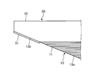
- FIG. 1 is a cross-sectional view schematically illustrating an example of a repair patch according to the first embodiment.
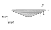
- FIG. 2 is a cross-sectional view schematically illustrating another example of the repair patch according to the first embodiment.
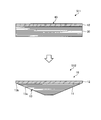
- FIG. 3 is an explanatory diagram relating to a method for forming a repair patch according to the first embodiment.
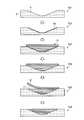
- FIG. 4 is a diagram illustrating an example of a method for repairing a composite material using the repair patch according to the first embodiment.
- FIG. 5 is an explanatory diagram of another example of the method for repairing a composite material using the repair patch according to the first embodiment.
- FIG. 6 is a graph related to the repair result of the repaired part repaired by the repair patch according to the first embodiment.
- FIG. 7 is a cross-sectional view schematically illustrating an example of a repair patch according to the second embodiment.
- the repair patch 10 is a repair material used when repairing a composite material.
- the method of repairing a composite material using the repair patch 10 is for repairing a defective portion formed on the composite material due to damage or the like, and repairing the repaired portion to be repaired.
- FIGS. 1 and 2 are cross-sectional views schematically illustrating an example of the repair patch according to the first embodiment.
- FIG. 3 is an explanatory diagram relating to a method for forming a repair patch according to the first embodiment.
- 4 and 5 are explanatory diagrams of an example of a method for repairing a composite material using the repair patch according to the first embodiment.
- FIG. 6 is a graph relating to the repair result of the repaired part 5 repaired by the repair patch according to the first embodiment.
- the repair patch 10 is formed using a composite material, and includes a patch body 11 and a margin 12.
- the patch body 11 has a truncated cone shape having a bottom surface 15, a top surface 14, and a side surface 13a.
- the top surface 14 and the side surface 13a are an adhesive surface 18 to be adhered to the portion to be repaired, and the bottom surface 15 is a surface opposite to the adhesive surface 18.
- the patch body 11 is obtained by laminating a plurality of prepregs as a reinforcing fiber base material in the thickness direction and temporarily curing (precuring) them. Note that a direction along a plane orthogonal to the thickness direction is an in-plane direction.
- the prepreg is obtained by impregnating a reinforcing fiber with a resin.
- the reinforcing fiber for example, carbon fiber is used, but is not limited to carbon fiber, and may be other plastic fiber, glass fiber, natural fiber or metal fiber.
- the resin is preferably a thermosetting resin, but may be a thermoplastic resin.
- the thermosetting resin is, for example, an epoxy resin.
- thermoplastic resin examples include polyether ether ketone (PEEK), polyether ketone ketone (PEKK), and polyphenylene sulfide (PPS).
- PEEK polyether ether ketone
- PEKK polyether ketone ketone
- PPS polyphenylene sulfide
- the resin is not limited to these, and other resins may be used. Further, in addition to molding using a prepreg, a method such as hand lay-up, resin infusion, RTM, or the like may be applied.
- the patch body 11 is formed into a truncated cone-shaped patch body 11 by laminating a plurality of prepregs and mechanically processing a preliminarily cured (precured) plate-shaped laminate.
- the bonding surface 18 has a top surface 14 and a side surface 13a.
- the bonding surface 18 has side surfaces 13a on both sides in the in-plane direction across the top surface 14. Is located.
- Each side surface 13a is a surface inclined linearly with respect to the thickness direction. That is, in the cross section shown in FIG. 1, the side surfaces 13 a on both sides are inclined with respect to the thickness direction so as to spread from the patch body 11 toward the margin 12. Note that the side surface 13a is a part of the inclined surface 13 formed from the patch body 11 to the margin 12.
- the bottom surface 15 is a boundary surface between the patch body 11 and the margin 12 and extends in the in-plane direction.
- the patch body 11 has a corner (edge) formed by the bottom surface 15 and the side surface 13a.
- the inclined surface 13 including the side surface 13a has a predetermined taper ratio. Assuming that the thickness of the patch body 11 in the thickness direction is D and the length in the in-plane direction along the boundary surface is L, the taper ratio is represented by “L: D”.
- the taper ratio of the inclined surface 13 in the first embodiment is such that when the thickness D is 1, the length L is 10 or more. Specifically, when the thickness D is 1, the length L is 30. Has become.
- the corner formed by the bottom surface 15 and the side surface 13a of the patch body 11 be an acute angle.
- the corners of the patch body 11 are sharpened, fiber meandering is likely to occur at the corners. Therefore, in the first embodiment, the following margin 12 is provided.
- the estimated margin 12 is provided on the side opposite to the adhesive surface 18 of the patch main body 11 in the thickness direction, that is, provided on the bottom surface 15 side of the patch main body 11 and is joined to the patch main body 11 so as to be detachable.
- the expected cost 12 is configured using, for example, a peel ply.
- the repair patch 10 shown in FIG. 1 has a configuration in which the prospective margin 12 is integrally joined to the patch body 11 by applying a peel ply as the prospective margin 12.
- the prospective margin 12 is not particularly limited to the peel ply, and any material may be used as long as it is a material that can be separated from the patch body 11.
- the estimated margin 12 has an inclined surface 13b that is continuous with the side surface 13a of the patch body 11 to be joined.
- the inclined surface 13b is a surface inclined linearly with respect to the thickness direction, and is formed on both sides in the in-plane direction in the cross section shown in FIG. That is, in the cross section shown in FIG. 1, the inclined surfaces 13 b on both sides are inclined so as to spread from the patch body 11 toward the margin 12 in the thickness direction.
- the inclined surface 13 b is a part of the inclined surface 13 formed from the patch body 11 to the margin 12.
- the repair patch 20 includes a patch body 11, a margin 12, and a bonding layer 23 provided between the patch body 11 and the margin 12. Note that the patch body 11 and the estimated cost 12 are the same as the repair patch 10 shown in FIG.
- the bonding layer 23 bonds the patch body 11 and the margin 12.
- the bonding layer 23 is bonded to the patch body 11 so that the margin 12 can be peeled off.
- the bonding layer 23 is configured using an adhesive.
- As the adhesive for example, a fluororesin adhesive or an acrylic resin adhesive is applied.
- the bonding layer 23 is provided, the patch main body 11 and the margin allowance 12 can be formed separately, so that the margin allowance 12 is not limited to the peel ply, and any material may be applied.
- the repair patch 10 is formed by machining the temporarily cured laminate 30. Note that, in the molding method of FIG. 3, the repair patch 10 of FIG. 1 will be described, but the repair patch 20 of FIG. 2 is also applicable.
- a laminated body 30 formed by laminating a plurality of reinforcing fiber bases in the thickness direction and the prospective margin 12 are joined to form an integrated repair kit 40 (Step S11: joining step).
- the repair kit 40 is the repair patch 10 before machining.
- the laminate 30 has a flat plate shape, and the margin 12 has the same flat plate shape.
- the margin 12 is joined to the surface of the stacked body 30 on the bottom surface 15 side of the patch body 11.
- the prospective margin 12 may be simultaneously cured by temporarily curing, or the laminated body 30 and the prospective margin may be temporarily cured, and then joined. Is not particularly limited.
- step S12 processing step.
- the repair kit 40 is used as the repair patch 10 by forming the inclined surface 13 from the laminate 30 to the margin allowance 12. That is, in the processing step S12, the side surface 13a of the patch main body 11 of the repair patch 10 is formed, and the inclined surface 13b is formed on the expected margin 12.
- FIG. 4 an example of a method for repairing a composite material having a portion to be repaired using the repair patch 10 will be described. Note that the repair method shown in FIG. 4 will be described using the repair patch 10 shown in FIG. 1, but the repair patch 20 shown in FIG. 2 is also applicable.
- the repair patch 10 described above and the resin sheet 28 as an adhesive are used.
- the resin sheet 28 is formed by forming a resin into a sheet shape, and is made of a material that can be bonded to the resin used for the repair patch 10.
- the resin sheet 28 may be the same as or different from the resin used for the repair patch 10, and is not particularly limited.
- a plurality of types of repair patches 10 having different diameters are prepared, and the repair patches 10 are appropriately selected and used according to the shape (size) of a counterbore 6 to be described later.
- the missing portion formed in the composite material is processed by cutting or the like to form the counterbore 6 having the shape shown in FIG. 4 (step S21).
- the counterbore 6 has an opening formed in a circular shape, and a bottom surface formed in a circular shape smaller than the opening. Further, the counterbore hole 6 is a surface that is inclined so that the side surface is widened from the bottom surface toward the opening portion.
- the counterbore 6 has a bottom surface and side surfaces serving as surfaces to which the repair patch 10 is bonded.
- Step S22 adhesive disposing step. Specifically, in the adhesive disposing step S22, the resin sheet 28 is disposed so as to be in contact with the inner surfaces of the counterbore holes 6 and cover these surfaces.
- Step S23 patch arrangement step.
- marking is performed on the surface of the expected margin 12 of the repair patch 10 and marking is performed on the surface of the composite material to be the repaired part 5, and the repair patch 10
- the repair patch 10 may be arranged in the counterbore 6 so that the position of the repair patch 10 becomes an appropriate position.
- Step S24 bonding step.
- the repair patch 10 and the resin sheet 28 are sealed by using a bag film or the like, and the repair patch 10 and the resin sheet 28 are heated while evacuating the sealed space. Then, the repair patch 10 and the resin sheet 35 are completely cured.
- Step S25 peeling step.
- the bottom surface 15 of the patch body 11 is exposed by peeling the margin 12 from the patch body 11.
- the repaired portion 5 is repaired by performing a finishing process on the surface of the composite material 1 to be the repaired portion and the bottom surface 15 of the patch body 11 (step S26).
- FIG. 5 is described with reference to the repair patch 10 shown in FIG. 1, the repair patch 20 shown in FIG. 2 is also applicable.
- the same parts as those in the repair method shown in FIG. 4 are partially omitted from description, and the same steps are described using the same reference numerals.
- Step S21 the missing portion formed in the composite material is processed by cutting or the like to form the counterbore 6 having the shape shown in FIG. 4 (step S21).
- step S22 adhesive disposing step.
- a repair kit 40 in which the laminate 30 and the margin 12 are integrally joined is prepared (step S31). Subsequently, as in step S12, the inclined surface 13 that is inclined from the laminated body 30 toward the prospective margin 12 in the thickness direction is formed on the repair kit 40 by machining, thereby forming the repair kit 40. 40 is set as the repair patch 10 (step S32).
- Step S23 patch arrangement step
- step S24 bonding step
- step S25 release step
- step S26 the repaired portion 5 is repaired by performing a finishing process on the surface of the composite material 1 to be the repaired portion and the bottom surface 15 of the patch body 11
- the vertical axis indicates the breaking strain.
- a repair patch used for repairing a portion to be repaired is one in which fiber meandering occurs at a corner (edge). Comparing the fracture strain between the conventional and the first embodiment, it was confirmed that the fracture strain of the first embodiment was larger than the conventional one. That is, it was confirmed that the repair of the repaired portion 5 using the repair patches 10 and 20 of the first embodiment has a greater strength recovery than in the related art.
- the thickness of the edge portion (outside) of the patch main body 11 is small, the thickness can be increased by the margin 12. For this reason, when forming the side surface 13a on the patch main body 11, since the inclined surface 13 can be formed by securing the strength by the margin allowance 12, the occurrence of fiber meandering at the edge side end of the patch main body 11 is suppressed. can do. Further, the margin on the edge side of the patch body 11 can be protected by the margin 12.
- the margin 12 in the repair patch 10 of FIG. 1, by making the margin 12 a peel ply, the margin 12 can be easily peeled off from the patch body 11.
- the patch body 11 and the margin 12 are connected via the bonding layer 23. Can be joined, and at the time of separation, the margin 12 can be separated from the patch body 11.
- the shape of the patch body 11 is reduced.
- a shape suitable for recovering the strength of the portion to be repaired 5 can be formed, and even with this shape, the occurrence of fiber meandering at the edge side end of the patch body 11 can be suppressed.
- the inclined surface 13 can be formed on the patch body 11 while securing the strength by the margin allowance 12, the occurrence of fiber meandering at the edge side edge of the patch body 11 is suppressed. can do. For this reason, the repair patch 10 having an appropriate shape can be formed.
- the patch body 11 is adhered to the repaired portion 5 in a state where the edge on the edge side of the patch body 11 is protected, and then the margin 12 is released. Can be done. For this reason, the patch main body 11 can be adhered to the part to be repaired 5 while suppressing the occurrence of fiber meandering at the edge side end of the patch main body 11.
- the adhesive surface 18 including the inclined surface 13 of the repair kit 40 can be processed according to the shape of the repaired part 5.
- the bonding surface 18 suitable for the shape of (1) can be formed.
- the inclined surface 13 can be formed in the laminate 30 while securing the strength by the margin allowance 12, the occurrence of fiber meandering at the edge side end of the laminate 30 can be suppressed.
- the prospective cost 12 is separated from the patch body 11 by peeling the prospective cost 12 from the patch body 11.
- it is modified so as to easily remove the prospective cost 12 using a solvent or the like. May be.
- the patch main body 11 has a truncated conical shape.
- the shape is not particularly limited to this, and any shape having the inclined surface 13 may be used.
- FIG. 7 is a cross-sectional view schematically illustrating an example of a repair patch according to the second embodiment.
- portions different from the first embodiment will be described in order to avoid redundant description, and portions having the same configuration as the first embodiment will be described with the same reference numerals.
- the repair patch 50 according to the second embodiment is obtained by further adding a release layer 51 to the repair patch 10 according to the first embodiment.
- the release layer 51 is provided on the inclined surface 13 b of the margin 12.
- the release layer 51 is, for example, an adhesive tape using a fluororesin such as Teflon (registered trademark).
- Teflon registered trademark
- the release layer 51 is not limited to the above-described adhesive tape, and may be formed by applying a fluororesin.
Landscapes
- Engineering & Computer Science (AREA)
- Mechanical Engineering (AREA)
- Chemical & Material Sciences (AREA)
- Composite Materials (AREA)
- Lining Or Joining Of Plastics Or The Like (AREA)
Priority Applications (2)
| Application Number | Priority Date | Filing Date | Title |
|---|---|---|---|
| EP19860626.1A EP3750698B1 (en) | 2018-09-12 | 2019-03-19 | Repair patch, repair patch molding method, and repair method for composite material |
| US16/979,733 US20210039341A1 (en) | 2018-09-12 | 2019-03-19 | Repair patch, method for molding repair patch, and method for repairing composite material |
Applications Claiming Priority (2)
| Application Number | Priority Date | Filing Date | Title |
|---|---|---|---|
| JP2018-170822 | 2018-09-12 | ||
| JP2018170822A JP7036694B2 (ja) | 2018-09-12 | 2018-09-12 | 修理パッチ及び複合材の修理方法 |
Publications (1)
| Publication Number | Publication Date |
|---|---|
| WO2020054111A1 true WO2020054111A1 (ja) | 2020-03-19 |
Family
ID=69777088
Family Applications (1)
| Application Number | Title | Priority Date | Filing Date |
|---|---|---|---|
| PCT/JP2019/011536 Ceased WO2020054111A1 (ja) | 2018-09-12 | 2019-03-19 | 修理パッチ、修理パッチの成形方法及び複合材の修理方法 |
Country Status (4)
| Country | Link |
|---|---|
| US (1) | US20210039341A1 (enExample) |
| EP (1) | EP3750698B1 (enExample) |
| JP (1) | JP7036694B2 (enExample) |
| WO (1) | WO2020054111A1 (enExample) |
Families Citing this family (5)
| Publication number | Priority date | Publication date | Assignee | Title |
|---|---|---|---|---|
| US12134240B2 (en) * | 2021-04-13 | 2024-11-05 | The Boeing Company | Methods for repairing composite material using pre-cured plugs |
| EP4344866A1 (en) * | 2022-09-30 | 2024-04-03 | Siemens Gamesa Renewable Energy A/S | Resin joining portion for wind turbine blades |
| US20240217192A1 (en) * | 2023-01-03 | 2024-07-04 | Rohr, Inc. | Method of repairing thermoplastic composite components with manual ultrasonic weld |
| EP4653181A1 (en) * | 2024-05-22 | 2025-11-26 | LM Wind Power A/S | A method for repairing a fiber-composite element having a locally deteriorated area, a repair patch for a fiber composite element, and a set of at least two repair patches |
| CN118849471B (zh) * | 2024-08-01 | 2025-09-09 | 嘉兴睿创新材料有限公司 | 一种沉头螺孔预制体结构及其制备方法 |
Citations (5)
| Publication number | Priority date | Publication date | Assignee | Title |
|---|---|---|---|---|
| JPS6124561B2 (enExample) | 1978-08-17 | 1986-06-11 | Daikin Kogyo Co Ltd | |
| JP2011173322A (ja) * | 2010-02-24 | 2011-09-08 | Mitsubishi Aircraft Corp | 繊維強化樹脂からなる部材の補修方法 |
| JP2013512808A (ja) * | 2009-12-08 | 2013-04-18 | ザ・ボーイング・カンパニー | 複合構造修復プロセスのサロゲートパッチ |
| WO2017081456A1 (en) * | 2015-11-11 | 2017-05-18 | Short Brothers Plc | Methods and patches for repairing composite laminates |
| JP2018114721A (ja) * | 2017-01-20 | 2018-07-26 | 三菱重工業株式会社 | 複合材の修理方法 |
Family Cites Families (5)
| Publication number | Priority date | Publication date | Assignee | Title |
|---|---|---|---|---|
| US4408958A (en) * | 1980-12-23 | 1983-10-11 | The Bendix Corporation | Wind turbine blade |
| US7927077B2 (en) | 2009-07-09 | 2011-04-19 | General Electric Company | Wind blade spar cap laminate repair |
| JP6124561B2 (ja) * | 2012-11-20 | 2017-05-10 | 三菱航空機株式会社 | 複合材の修理方法 |
| US20160121585A1 (en) | 2014-11-04 | 2016-05-05 | Spintech, LLC | Thermoplastic polymer repair patches and methods of using the same |
| US9539767B2 (en) * | 2014-12-05 | 2017-01-10 | The Boeing Company | Forming of staged thermoset composite materials |
-
2018
- 2018-09-12 JP JP2018170822A patent/JP7036694B2/ja active Active
-
2019
- 2019-03-19 EP EP19860626.1A patent/EP3750698B1/en active Active
- 2019-03-19 US US16/979,733 patent/US20210039341A1/en not_active Abandoned
- 2019-03-19 WO PCT/JP2019/011536 patent/WO2020054111A1/ja not_active Ceased
Patent Citations (5)
| Publication number | Priority date | Publication date | Assignee | Title |
|---|---|---|---|---|
| JPS6124561B2 (enExample) | 1978-08-17 | 1986-06-11 | Daikin Kogyo Co Ltd | |
| JP2013512808A (ja) * | 2009-12-08 | 2013-04-18 | ザ・ボーイング・カンパニー | 複合構造修復プロセスのサロゲートパッチ |
| JP2011173322A (ja) * | 2010-02-24 | 2011-09-08 | Mitsubishi Aircraft Corp | 繊維強化樹脂からなる部材の補修方法 |
| WO2017081456A1 (en) * | 2015-11-11 | 2017-05-18 | Short Brothers Plc | Methods and patches for repairing composite laminates |
| JP2018114721A (ja) * | 2017-01-20 | 2018-07-26 | 三菱重工業株式会社 | 複合材の修理方法 |
Non-Patent Citations (1)
| Title |
|---|
| See also references of EP3750698A4 |
Also Published As
| Publication number | Publication date |
|---|---|
| JP7036694B2 (ja) | 2022-03-15 |
| EP3750698A1 (en) | 2020-12-16 |
| US20210039341A1 (en) | 2021-02-11 |
| EP3750698B1 (en) | 2022-05-18 |
| JP2020040341A (ja) | 2020-03-19 |
| EP3750698A4 (en) | 2021-11-10 |
Similar Documents
| Publication | Publication Date | Title |
|---|---|---|
| WO2020054111A1 (ja) | 修理パッチ、修理パッチの成形方法及び複合材の修理方法 | |
| WO2020054220A1 (ja) | 修理パッチ、修理パッチの成形方法及び複合材の修理方法 | |
| CN101903162A (zh) | 一种用于修理纤维复合物固体构件的方法 | |
| JP5891244B2 (ja) | 複合材半径部を圧縮する方法および装置 | |
| JP2018203229A5 (enExample) | ||
| US8382924B2 (en) | Multi-stage debulk and compaction of thick composite repair laminates | |
| CN112046037B (zh) | 将包括复合材料的第一部分和第二部分进行整合的方法 | |
| JP2020040341A5 (enExample) | ||
| JP6946143B2 (ja) | 修理パッチ、修理パッチの成形方法、複合材の修理方法及び成形治具 | |
| JP6949474B2 (ja) | 複合材及び複合材の成形方法 | |
| US20060011294A1 (en) | Method for production of a laminate from metal layers and fibre reinforced plastic layers | |
| EP4074499A1 (en) | Methods for repairing composite material using pre-cured plugs | |
| JP2019072947A5 (enExample) | ||
| US9579855B2 (en) | Secondary groove for work piece retention during machining | |
| EP2662203A2 (en) | Contour caul with expansion region and method for its manufacture | |
| JP2004148700A (ja) | 複合材製ラミネートシムとその製作方法 | |
| JP7065168B2 (ja) | 修理パッチ、被修理部の修理方法及び補修部 | |
| JP6820753B2 (ja) | 修理パッチの成形方法 | |
| JP4464208B2 (ja) | ハニカムサンドイッチパネルの製造方法 | |
| EP4467328A1 (en) | Method for manufacturing spars or ribs for aircrafts | |
| CN108929637A (zh) | 粘合层控制粘合剂间隔物 | |
| CN120056492A (zh) | 修复复合材料元件的方法 | |
| JPH01259912A (ja) | 熱硬化樹脂系複合材の成形方法 |
Legal Events
| Date | Code | Title | Description |
|---|---|---|---|
| 121 | Ep: the epo has been informed by wipo that ep was designated in this application |
Ref document number: 19860626 Country of ref document: EP Kind code of ref document: A1 |
|
| ENP | Entry into the national phase |
Ref document number: 2019860626 Country of ref document: EP Effective date: 20200910 |
|
| NENP | Non-entry into the national phase |
Ref country code: DE |