WO2020054043A1 - 光学装置および顕微鏡 - Google Patents
光学装置および顕微鏡 Download PDFInfo
- Publication number
- WO2020054043A1 WO2020054043A1 PCT/JP2018/034084 JP2018034084W WO2020054043A1 WO 2020054043 A1 WO2020054043 A1 WO 2020054043A1 JP 2018034084 W JP2018034084 W JP 2018034084W WO 2020054043 A1 WO2020054043 A1 WO 2020054043A1
- Authority
- WO
- WIPO (PCT)
- Prior art keywords
- laser light
- optical device
- tilt
- collimator lens
- lens
- Prior art date
- Legal status (The legal status is an assumption and is not a legal conclusion. Google has not performed a legal analysis and makes no representation as to the accuracy of the status listed.)
- Ceased
Links
Images





Classifications
-
- G—PHYSICS
- G02—OPTICS
- G02B—OPTICAL ELEMENTS, SYSTEMS OR APPARATUS
- G02B21/00—Microscopes
- G02B21/06—Means for illuminating specimens
-
- G—PHYSICS
- G02—OPTICS
- G02B—OPTICAL ELEMENTS, SYSTEMS OR APPARATUS
- G02B6/00—Light guides; Structural details of arrangements comprising light guides and other optical elements, e.g. couplings
- G02B6/24—Coupling light guides
- G02B6/26—Optical coupling means
- G02B6/32—Optical coupling means having lens focusing means positioned between opposed fibre ends
Definitions
- the present invention relates to an optical device that causes a laser beam (laser beam) emitted from a laser light source to enter an optical fiber, and a microscope including the optical device.
- a laser beam laser beam
- a shifter that moves the laser light in a direction perpendicular to the optical axis and a tilt mirror that can adjust the angle of the reflection surface with respect to the incident optical axis are used. It is known (see Patent Document 1).
- the optical device includes a collimator lens that converts incident light into parallel light, a condenser lens that collects light transmitted through the collimator lens, and a center of light emitted from the collimator lens.
- a tilt adjustment member that adjusts the inclination of the line with respect to the optical axis of the condenser lens, and a shift correction member that adjusts the distance between the center line of the light and the optical axis of the condenser lens; , Provided in an optical path between the tilt adjustment member and the shift adjustment member.
- An optical device includes a collimator lens that converts incident light into parallel light, a condenser lens that collects light transmitted through the collimator lens, and a center of light emitted from the collimator lens.
- a tilt adjusting member that adjusts the inclination of the line with respect to the optical axis of the condenser lens; and a shift correction member that adjusts the distance between the center line of the light and the optical axis of the condenser lens. Adjusting the center line of the light so as to pass through the front focal position of the condenser lens, and adjusting the tilt of the center line of the light with respect to the optical axis with respect to the front focal position of the condenser lens. adjust.
- the microscope according to the third aspect includes an optical fiber and an optical device that causes a laser beam emitted from a laser light source to enter the optical fiber, wherein the optical device is the above-described optical device.
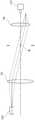
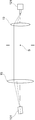
- FIG. 4 is an optical path diagram showing an ideal state of laser light.
- FIG. 3 is an optical path diagram showing a tilt of a laser beam.
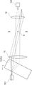
- FIG. 3 is an optical path diagram showing a shift of laser light.
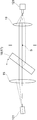
- FIG. 4 is an optical path diagram illustrating a principle of adjusting a tilt of a laser beam.
- FIG. 3 is an optical path diagram illustrating a principle of adjusting a shift of a laser beam.
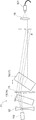
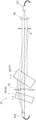
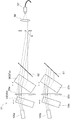
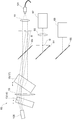
- FIG. 1 is a schematic configuration diagram of an optical device according to a first embodiment. It is a schematic structure figure of an optical device concerning a 2nd embodiment. It is a schematic structure figure of an optical device concerning a 3rd embodiment. It is a schematic structure figure showing the modification of an optical device. It is a schematic structure figure of an optical device concerning a 4th embodiment.
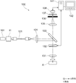
- the microscope 100 shown in FIG. 14 includes a laser light source 101, an optical fiber 121, an illumination lens 124, and the optical device 11.
- the microscope 100 includes an objective lens 131, a scanning mechanism (scanner) 132, a dichroic mirror 133, a condenser lens 135, a pinhole 136, a barrier filter 137 and a photodetector 138.
- the laser light source 101 emits a laser beam (laser beam) having a predetermined wavelength (for example, an arbitrary wavelength selected from a wavelength range of 400 to 700 nm).
- the optical device 11 condenses the laser light emitted from the laser light source 101 and makes it incident on one end of the optical fiber 121.
- the laser light that has entered one end of the optical fiber 121 exits from the other end of the optical fiber 121 and passes through the illumination lens 124.
- the laser light that has passed through the illumination lens 124 and has become substantially parallel is reflected by the dichroic mirror 133 as illumination light, and passes through a scanning mechanism (scanner) 132.
- the scanning mechanism 132 has two mirrors, and scans the incident laser light on the sample A in the x direction and the y direction. Note that the scanning mechanism 132 may have a galvano mirror or a resonant mirror as a mirror.
- the laser beam passing through the scanning mechanism (scanner) 132 passes through the objective lens 131 and is focused toward the sample A.
- the sample A contains a fluorescent substance
- fluorescence is generated when the sample A is irradiated with laser light.
- Light (for example, fluorescence) generated by the sample A passes through the objective lens 131, passes through the scanning mechanism 132, and passes through the dichroic mirror 133.
- the light transmitted through the dichroic mirror 133 is transmitted through the condenser lens 135 and is focused toward the pinhole 136.
- the pinhole 136 has a conjugate relationship with the focal position of the objective lens 131, and of the light from the sample A, only the light from the focal plane of the objective lens 131 passes through the pinhole 136.
- the light passing through the pinhole 136 passes through the barrier filter 137 and reaches the photodetector 138.
- the photodetector 138 detects only the light that has passed through the pinhole 136 (that is, light from the focal plane of the objective lens 131) out of the light from the sample A, and outputs the detection signal to the computer 141.
- the computer 141 is electrically connected to the detector 138 and the monitor 142, and generates image data of the sample A from a detection signal input from the photodetector 138 based on a predetermined image processing program. Can be displayed on the monitor 142.
- the computer 141 is electrically connected to the scanning mechanism (scanner) 132 and controls the operation of the scanning mechanism 132 based on a predetermined control program.
- the microscope 100 is not limited to the optical device 11 and the laser light source 101 according to the first embodiment, and may include the optical device 21 and the laser light source 102 according to the second embodiment.
- the optical device 41 and the laser light source 104 according to the fourth embodiment may be provided.
- the microscope 100 may include the optical device 51 and the laser light sources 105a and 105b according to the fifth embodiment, and may include the optical device 60 and the laser light source 106 according to the sixth embodiment.
- An optical device 70 and laser light sources 107a and 107b according to the embodiment may be provided.
- the optical device 11 is an optical device that causes the laser light emitted from the laser light source 101 to enter the optical fiber 121 as described above.
- laser light emitted from a laser light source 101 passes through a collimator lens 15 and a condenser lens 19 and is condensed on an end of an optical fiber 121.
- the traveling axis (principal ray) of the light coincides with the optical axis of the optical device.
- the traveling axis of the laser light may be deviated from the optical axis due to a mounting error of the laser light source 101 or the like.
- a deviation in which the traveling axis (principal ray) of the laser light is inclined with respect to the optical axis at the front focal position S of the condenser lens 19 is referred to as a tilt of the laser light.
- the laser light source 101 moves in parallel in a direction perpendicular to the optical axis and shifts. Then, the tilt of the laser light with the front focal position S of the condenser lens 19 as the tilt center occurs.
- the condensing position of the laser light is displaced in a direction perpendicular to the optical axis, so that the light amount loss of the laser light incident on the end of the optical fiber 121 occurs.
- a shift of the traveling axis (principal ray) of the laser light in parallel with the optical axis at the front focal position S of the condenser lens 19 is referred to as a shift of the laser light.
- a shift of the laser light occurs.
- the principal ray of the laser light transmitted through and condensed through the condenser lens 19 is inclined with respect to the optical axis, so that the light amount loss of the laser light entering the end of the optical fiber 121 occurs.
- the laser light emitted from the laser light source 101 is displaced so as to be closer to the optical axis of the optical device, for example, as shown by a broken line in FIG.
- the laser light is adjusted so that the traveling axis (principal ray) of the laser light emitted from the laser light source 101 is parallel to the optical axis of the optical device.
- the tilt of the laser light decreases.
- the principal ray of the laser light emitted from the laser light source 101 coincides with the optical axis, the tilt of the laser light becomes zero.
- the loss of the light amount of the laser light incident on the end of the optical fiber 121 is reduced.
- the laser light emitted from the laser light source 101 is displaced closer to the optical axis. It is possible to do.
- FIG. 4 shows an example in which the tilt adjusting parallel plate 14 is rotationally displaced around an axis extending in a direction perpendicular to the plane of the paper of FIG. 4, but in practice, the tilt adjusting parallel plate 14 is It is possible to rotationally displace in two rotational directions about an axis perpendicular to the axis. Also, a first tilt adjusting parallel plate that can be rotationally displaced about an axis extending in a direction perpendicular to the paper surface of FIG. 4 and a second tilt adjusting parallel plate that can be rotationally displaced about an axis extending in the vertical direction of FIG.
- the flat plate and the flat plate may be arranged along the optical axis of the optical device.
- the laser light transmitted through the collimator lens 15 is displaced so as to be closer to the optical axis of the optical device, for example, as shown by a broken line in FIG.
- the traveling axis (principal ray) of the laser beam transmitted through the collimator lens 15 coincides with the optical axis, the shift of the laser beam becomes zero. Thereby, the loss of the light amount of the laser light incident on the end of the optical fiber 121 is reduced.
- the laser light transmitted through the collimator lens 15 is brought closer to the optical axis. It is possible to displace.
- FIG. 5 shows an example in which the shift adjusting parallel plate 17 is rotationally displaced about an axis extending in a direction perpendicular to the paper surface of FIG. 5. It is possible to rotationally displace in two rotational directions about an axis perpendicular to the axis. Further, a first parallel plate for shift adjustment rotatable about an axis extending in a direction perpendicular to the paper surface of FIG. 5, and a second parallel plate for shift adjustment rotatable about an axis extending in the vertical direction of FIG. The flat plate and the flat plate may be arranged along the optical axis of the optical device.
- the tilt adjustment parallel plate 14 is rotationally displaced about an axis perpendicular to the optical axis of the optical device, so that the tilt of the laser beam transmitted through the collimator lens 15 is eliminated (or reduced). Adjust).
- the traveling axis (principal ray) of the laser beam transmitted through the collimator lens 15 shifts the front focal position S of the condenser lens 19. Adjust to pass.
- the center line of the light emitted from the collimator lens is a light beam that becomes the center of the intensity distribution of the light emitted from the collimator lens. This center line coincides with the principal ray of the laser beam in the following embodiments.
- the optical device 11 includes a collimator lens 15, a condenser lens 19, a tilt adjustment unit 13, and a shift adjustment unit 16, as shown in FIG.
- the collimator lens 15 is composed of a convex lens, and transmits laser light (laser beam) from the laser light source 101.
- the laser light source 101 according to the first embodiment emits diverging laser light, and is adjusted such that the emitted (diverging) laser light becomes a substantially parallel light flux when transmitted through the collimator lens 15.
- the condensing lens 19 is composed of a convex lens, and condenses the laser light transmitted through the collimator lens 15 to the end of the optical fiber 121.
- the end of the optical fiber 121 is arranged at the rear focal position of the condenser lens 19.
- the collimator lens 15 and the condenser lens 19 are arranged so that the front focal position S of the condenser lens 19 and the rear focal position of the collimator lens 15 are the same. With this arrangement, the laser beam converted into a substantially parallel light beam by the collimator lens 15 enters the condenser lens 19 and is condensed on the end of the optical fiber 121.
- the tilt adjusting unit 13 includes a tilt adjusting parallel plate 14 disposed between the collimator lens 15 and the laser light source 101.
- the tilt adjusting parallel plate 14 is rotatably held by a tilt adjusting rotation holding mechanism (not shown).
- the tilt adjusting parallel flat plate 14 can be rotationally displaced in a two-axis rotation direction about a axis perpendicular to the optical axis from a position orthogonal to the optical axis of the optical device 11 by the tilt adjusting rotation holding mechanism. it can.
- FIG. 6 shows an example in which the tilt adjusting parallel plate 14 is rotationally displaced around an axis extending in a direction perpendicular to the plane of FIG. 6 through the center axis (optical axis) of the tilt adjusting parallel plate 14.
- the shift adjustment unit 16 includes a shift adjustment parallel flat plate 17 disposed between the collimator lens 15 and the front focal position S of the condenser lens 19.
- the shift adjustment parallel flat plate 17 is rotatably held by a shift adjustment rotation holding mechanism (not shown).
- the shift adjustment parallel flat plate 17 can be rotationally displaced in a two-axis rotation direction about an axis perpendicular to the optical axis from a position orthogonal to the optical axis of the optical device 11 by the shift adjustment rotation holding mechanism. it can.
- FIG. 6 shows an example in which the shift adjusting parallel plate 17 is rotationally displaced around an axis extending in a direction perpendicular to the plane of FIG. 6 through the central axis (optical axis) of the shift adjusting parallel plate 17.
- the laser light emitted from the laser light source 101 passes through the tilt adjusting parallel plate 14, the collimator lens 15, the shift adjusting parallel plate 17, and the condenser lens 19. Then, the light is incident (collected) on the end of the optical fiber 121.
- the first embodiment as an example, a description will be given of an adjustment method in the case where the laser light source 101 is tilted upwardly in FIG. 6 with respect to the optical axis of the optical device 11 to tilt and shift the laser light. I do.
- the tilt adjusting parallel plate 14 is rotationally displaced around an axis perpendicular to the optical axis so that the laser light emitted from the laser light source 101 is obliquely incident on the tilt adjusting parallel plate 14.
- the rotational displacement amount of the tilt adjusting parallel plate 14 is adjusted so that the traveling axis (principal ray) of the laser light emitted from the laser light source 101 becomes parallel to the optical axis and the laser light does not tilt.
- the tilt of the laser light emitted from the laser light source 101 is corrected. Since the tilt of the laser light transmitted through the tilt adjusting parallel plate 14 has been corrected, the tilt of the laser light transmitted through the collimator lens 15 disappears (or becomes smaller than before the adjustment).
- the laser light transmitted through the collimator lens 15 is shifted upward with respect to the front focal position S of the condenser lens 19 in FIG. Therefore, the shift adjusting parallel plate 17 is rotationally displaced about an axis perpendicular to the optical axis so that the laser beam transmitted through the collimator lens 15 is incident on the shift adjusting parallel plate 17 in an oblique direction.
- the rotational displacement of the shift adjusting parallel plate 17 is adjusted so that the traveling axis (principal ray) of the laser beam transmitted through the shift adjusting parallel plate 17 passes through the front focal position S of the condenser lens 19.
- the laser beam transmitted through the collimator lens 15 is incident on the shift adjustment parallel plate 17 in an oblique direction, and is closer to the optical axis than the position on the optical axis or before the adjustment (below in FIG. 6). Emitted from the position.
- the laser beam transmitted through the shift adjusting parallel flat plate 17 passes through the front focal position S of the condenser lens 19, enters the condenser lens 19, and passes through the condenser lens 19. Then, the laser light transmitted through the condenser lens 19 is condensed at the rear focal position (or in the vicinity thereof) of the condenser lens 19 and is incident (condensed) on the end of the optical fiber 121.
- the tilt of the laser beam can be adjusted independently of the shift by the tilt adjusting unit 13, and the shift of the laser beam can be adjusted independently of the tilt by the shift adjusting unit 16.
- the laser light emitted from the laser light source 101 can be condensed on the end of the optical fiber 121 disposed at the rear focal position of the condenser lens 19 with high accuracy. Thereby, the loss of the light amount of the laser light incident on the end of the optical fiber 121 is reduced.
- the tilt adjusting unit 13 adjusts the tilt of the laser beam by rotating and displacing the tilt adjusting parallel plate 14 about an axis perpendicular to the optical axis.
- the tilt of the laser beam can be adjusted with a simple configuration using a parallel plate.
- the collimator lens 15 and the condenser lens 19 are arranged such that the front focal position S of the condenser lens 19 and the rear focal position of the collimator lens 15 are the same.
- the tilt of the laser beam can be adjusted with the front focal position S of the condenser lens 19 as the tilt center, and the laser beam is rotated by displacing the tilt adjusting parallel plate 14 about an axis perpendicular to the optical axis. Only the tilt of light can be adjusted independently. When the shift is not adjusted and the laser light is shifted, the tilt center is shifted, but the adjustment is performed on substantially the same principle.
- the shift adjusting unit 16 adjusts the shift of the laser beam by rotating and displacing the shift adjusting parallel plate 17 about an axis perpendicular to the optical axis. This makes it possible to adjust the shift without changing the tilt of the laser beam with a simple configuration using a parallel plate.
- the shift and tilt of the laser light if the amount of shift of the laser light is not large, it is easy to introduce light into the optical fiber by performing the tilt adjustment first, but the shift adjustment must be performed first. The adjustment may be performed, or the adjustment may be performed alternately and repeatedly.
- the optical device 21 includes a diverging lens 22, a collimator lens 15, a condenser lens 19, a tilt adjustment unit 13, and a shift adjustment unit 16, as shown in FIG.
- the collimator lens 15, the condenser lens 19, the tilt adjustment unit 13, and the shift adjustment unit 16 have the same configurations as those in the first embodiment.
- the detailed description is omitted.
- the diverging lens 22 includes a concave lens, and diverges the laser light (laser beam) emitted from the laser light source 102.
- the laser light emitted from the laser light source 102 according to the second embodiment is a convergent light or a parallel light, and is adjusted so that the laser light diverged by the diverging lens 22 becomes a substantially parallel light flux when transmitted through the collimator lens 15. Have been.
- the laser light emitted from the laser light source 102 is condensed by the diverging lens 22, the tilt adjusting parallel plate 14, the collimator lens 15, the shift adjusting parallel plate 17, The light passes through the lens 19 and is incident (condensed) on the end of the optical fiber 121.
- the laser light emitted from the laser light source 102 is diverged by the diverging lens 22 and is incident on the tilt adjusting parallel plate 14.
- the collimator lens 15, the condenser lens 19, and the tilt adjusting unit 13 and the shift adjustment unit 16 have the same configuration as in the first embodiment.
- the laser light emitted from the laser light source 102 is converged, but may be parallel light. Therefore, similarly to the first embodiment, the tilt of the laser light emitted from the laser light source 102 can be adjusted by rotating and displacing the tilt adjusting parallel plate 14 about an axis perpendicular to the optical axis. Further, similarly to the first embodiment, the shift of the laser light emitted from the laser light source 102 can be adjusted by rotating and displacing the shift adjusting parallel plate 17 about an axis perpendicular to the optical axis.
- the same effects as those of the first embodiment can be obtained. Further, by providing the diverging lens 22 for diverging the laser light emitted from the laser light source 102, even when the laser light emitted from the laser light source 102 is convergent light or parallel light, the tilt adjusting parallel flat plate 14 can be moved along the optical axis. The tilt of the laser beam can be adjusted with a simple configuration using a parallel plate by rotating and displacing the rotation about an axis perpendicular to the axis.
- the optical device 31 according to the third embodiment includes a collimator lens 15, a condenser lens 19, a tilt adjustment unit 13, and a shift adjustment unit 16, as shown in FIG.
- the collimator lens 15, the condensing lens 19, the tilt adjustment unit 13, and the shift adjustment unit 16 have the same configurations as those in the first embodiment, and thus have the same reference numerals as those in the first embodiment.
- the detailed description is omitted.
- the laser light source 103 according to the third embodiment is configured to emit laser light (laser beam) from an optical fiber.
- the laser light source 103 according to the third embodiment is adjusted so that a diverging laser beam is emitted, and when the emitted (diverging) laser beam passes through the collimator lens 15, it becomes a substantially parallel light flux.
- the laser light emitted from the laser light source 103 passes through the tilt adjusting parallel plate 14, the collimator lens 15, the shift adjusting parallel plate 17, and the condenser lens 19. Then, the light is incident (collected) on the end of the optical fiber 121.
- the collimator lens 15, the condenser lens 19, the tilt adjustment unit 13, and the shift adjustment unit 16 have the same configuration as in the first embodiment.
- the tilt of the laser beam emitted from the laser light source 103 can be adjusted by rotating and displacing the tilt adjusting parallel plate 14 about an axis perpendicular to the optical axis.
- the shift of the laser light emitted from the laser light source 103 can be adjusted by rotating and displacing the shift adjusting parallel plate 17 about an axis perpendicular to the optical axis.
- one tilt adjusting parallel plate 14 is provided between the collimator lens 15 and the laser light sources 101 to 103, but the present invention is not limited to this.
- a plurality of parallel plates (not shown) for tilt adjustment may be provided.
- the plurality of parallel flat plates for tilt adjustment have different plate thicknesses and are arranged so as to be arranged along the optical axis of the optical device.
- the tilt of the laser beam can be finely adjusted.
- the tilt of the laser beam can be significantly and finely adjusted by rotating and displacing the tilt adjusting parallel plates having different plate thicknesses around the axis perpendicular to the optical axis.
- one shift adjusting parallel plate 17 is provided between the collimator lens 15 and the front focal position S of the condenser lens 19; Instead, a plurality of parallel plates (not shown) for shift adjustment may be provided.
- the plurality of parallel plates for shift adjustment have different plate thicknesses and are arranged so as to be arranged along the optical axis of the optical device.
- the shift of the laser beam can be finely adjusted.
- the shift of the laser beam can be significantly and finely adjusted by rotationally displacing the shift adjusting parallel plates having different plate thicknesses around the axis perpendicular to the optical axis.
- one end of the optical fiber 121 is disposed on the optical axis of the optical device.
- the present invention is not limited to this. It may be arranged shifted.
- the tilt of the laser beam emitted from the laser light source 101 is reduced by rotating and displacing the tilt adjusting parallel plate 14 about an axis perpendicular to the optical axis.
- the position of the optical fiber 121 is adjusted by adjusting the shift of the laser light emitted from the laser light source 101 by rotating and shifting the parallel plate 17 for shift adjustment about an axis perpendicular to the optical axis. Adjust light shift and tilt.
- the rear focal position S of the collimator lens 15 and the front focal position S of the condenser lens 19 coincide with each other.
- the rear focal position C of the collimator lens 15 and the condenser lens 19 Is shifted from the front focal position S of the collimator lens 15, but the amount of deviation between the rear focal position C of the collimator lens 15 and the front focal position S of the condenser lens 19 is 20% or less of the focal length of the collimator lens 15. Is preferred.
- the coupling efficiency with respect to the optical fiber 121 (optical fiber This is because the loss of the amount of laser light incident on the end of the laser beam 121 decreases to an unacceptable level.
- the collimator lens 15 whose rear focal position coincides with the front focal position S of the condenser lens 19 is indicated by a solid line, and the rear focal position C is different from the front focal position S of the condenser lens 19.
- the shifted collimator lens 15 is indicated by a two-dot chain line.
- the focal length of the collimator lens 15 is 500 [mm]
- the focal length of the condenser lens 19 is 5 [mm]
- the diameter of the core of the optical fiber 121 (single mode fiber) is 3 [ ⁇ m].
- one end (center axis) of the optical fiber 121 is displaced from the optical axis of the optical device in a direction perpendicular to the optical axis within a range of the core diameter (3 [ ⁇ m]). It is assumed that In such a case, it is assumed that the condensing position of the laser beam by the condensing lens 19 is shifted in a direction perpendicular to the optical axis by the diameter of the core (3 [ ⁇ m]).
- the amount of deviation between the rear focal position C of the collimator lens 15 and the front focal position S of the condenser lens 19 is preferably 20% or less of the focal length of the collimator lens 15.
- the optical device 41 includes a divergent lens 42, a collimator lens 45, a condenser lens 49, a tilt adjustment unit 43, and a shift adjustment unit 46, as shown in FIG.
- the diverging lens 42 includes a concave lens, and diverges the laser light (laser beam) emitted from the laser light source 104.
- the collimator lens 45 is formed of a convex lens, and transmits the laser light from the diverging lens 42.
- the laser light emitted from the laser light source 104 is a convergent light or a parallel light, and is adjusted so that the laser light diverged by the diverging lens 42 becomes a substantially parallel light flux when transmitted through the collimator lens 45. Have been.
- the condensing lens 49 is formed of a convex lens, and condenses the laser light from the collimator lens 45 on the end of the optical fiber 121. Note that the end of the optical fiber 121 is disposed at the rear focal position of the condenser lens 49.
- the first relay lens 48a is provided between the front focal position S of the condenser lens 49 and the collimator lens 45 so that the front focal position S of the condenser lens 49 and the collimator lens 45 have a substantially conjugate positional relationship.
- a second relay lens 48b is provided between the front focal position S of the condenser lens 49 and the collimator lens 45 so that the front focal position S of the condenser lens 49 and the collimator lens 45 have a substantially conjugate positional relationship.
- the tilt adjusting unit 43 includes a lens driving unit (not shown) that can move the collimator lens 45 two-dimensionally in a direction perpendicular to the optical axis.
- the tilt adjusting unit 43 translates the collimator lens 45 in a direction perpendicular to the optical axis to displace an incident position (in a direction perpendicular to the optical axis) of the laser light to the collimator lens 45, thereby changing the laser light.
- FIG. 10 shows an example in which the collimator lens 45 is translated in the vertical direction in FIG.
- the shift adjusting section 46 includes a shift adjusting parallel flat plate 47 disposed between the collimator lens 45 and the first relay lens 48a.
- the shift adjustment parallel flat plate 47 is rotatably held by a shift adjustment rotation holding mechanism (not shown).
- the shift adjustment parallel flat plate 47 can be rotationally displaced in a two-axis rotation direction about a axis perpendicular to the optical axis from a position orthogonal to the optical axis of the optical device 41 by the shift adjustment rotation holding mechanism. it can.
- FIG. 10 shows an example in which the shift adjusting parallel plate 47 is rotationally displaced around an axis extending in a direction perpendicular to the plane of FIG. 10 through the central axis (optical axis) of the shift adjusting parallel plate 47.
- the laser light emitted from the laser light source 104 is condensed by the collimator lens 45, the shift adjustment parallel plate 47, the first relay lens 48a and the second relay lens 48b.
- the light passes through the lens 49 and is incident (collected) on the end of the optical fiber 121.
- the tilt adjusting unit 43 moves the collimator lens 45 in a direction perpendicular to the optical axis (downward in FIG. 10).
- the moving amount of the collimator lens 45 is adjusted so that the traveling axis (principal ray) of the laser light emitted from the laser light source 104 becomes parallel to the optical axis and the laser light does not tilt.
- the tilt of the laser light emitted from the laser light source 104 is corrected. Since the tilt of the laser light transmitted through the collimator lens 45 is corrected, the tilt of the laser light transmitted through the collimator lens 45 is eliminated (or smaller than before the adjustment).
- the shift adjusting parallel plate 47 is rotationally displaced about an axis perpendicular to the optical axis such that the laser beam transmitted through the collimator lens 45 is incident on the shift adjusting parallel plate 47 in an oblique direction.
- the rotational displacement of the shift adjusting parallel plate 47 is adjusted such that the traveling axis (principal ray) of the laser beam transmitted through the shift adjusting parallel plate 47 passes through the front focal position S of the condenser lens 49.
- the laser beam transmitted through the collimator lens 45 is obliquely incident on the parallel plate 47 for shift adjustment, and is closer to the optical axis than the position on the optical axis or before the adjustment (upper in FIG. 10). Emitted from the position.
- the laser light transmitted through the shift adjusting parallel plate 47 is transmitted through the first relay lens 48a and the second relay lens 48b, passes through the front focal position S of the condenser lens 49, enters the condenser lens 49, and is condensed.
- the light passes through the lens 49.
- the laser light transmitted through the condenser lens 49 is condensed at the rear focal position (or in the vicinity thereof) of the condenser lens 49 and is incident (condensed) on the end of the optical fiber 121.
- the tilt of the laser beam can be adjusted independently of the shift by the tilt adjusting unit 43, and the shift of the laser beam can be adjusted by the shift adjusting unit 46 independently of the tilt.
- the laser light emitted from the laser light source 104 can be precisely condensed on the end of the optical fiber 121 disposed at the rear focal position of the condenser lens 49. Thereby, the loss of the light amount of the laser light incident on the end of the optical fiber 121 is reduced.
- the tilt adjustment unit 43 adjusts the tilt of the laser beam by moving the collimator lens 45 in a direction perpendicular to the optical axis.
- the tilt of the laser beam can be adjusted with a simple configuration that simply moves the collimator lens 45.
- a first relay lens 48a and a second relay lens 48b are provided between the front focal position S of the condenser lens 49 and the collimator lens 45.
- the tilt of the laser light can be adjusted with the front focal position S of the condenser lens 49 as the tilt center, and only the tilt of the laser light can be adjusted by moving the collimator lens 45 in a direction perpendicular to the optical axis. Can be adjusted independently.
- the shift adjusting unit 46 adjusts the shift of the laser beam by rotating and displacing the shift adjusting parallel plate 47 about an axis perpendicular to the optical axis. This makes it possible to adjust the shift without changing the tilt of the laser beam with a simple configuration using a parallel plate.
- the diverging lens 42 is provided, but the present invention is not limited to this.
- the laser light source emits diverging laser light
- the diverging lens 42 may not be provided.
- the laser light emitted (diverged) from the laser light source is adjusted so as to become a substantially parallel light flux when transmitted through the collimator lens 45. Even in this case, the same effect as in the fourth embodiment can be obtained.
- one shift adjustment parallel flat plate 47 is provided between the collimator lens 45 and the first relay lens 48a.
- a parallel plate (not shown) for shift adjustment may be provided.
- the plurality of parallel plates for shift adjustment have different plate thicknesses and are arranged so as to be arranged along the optical axis of the optical device.
- the shift of the laser beam can be finely adjusted.
- the shift of the laser beam can be significantly and finely adjusted by rotationally displacing the shift adjusting parallel plates having different plate thicknesses around the axis perpendicular to the optical axis.
- one end of the optical fiber 121 is disposed on the optical axis of the optical device 41.
- the present invention is not limited to this, and one end of the optical fiber 121 may be shifted from the optical axis of the optical device 41. May be arranged.
- the shift and the tilt of the laser light are adjusted according to the position of the optical fiber 121, as in the fourth embodiment.
- the rear focal position of the collimator lens 45 and the front focal position S of the condenser lens 49 at the initial position before moving the collimator lens 45 coincide with each other. They do not necessarily have to match.
- the rear focal position of the collimator lens 45 and the front focal point of the condenser lens 49 at the initial position when the initial position of the collimator lens 45 deviates from the ideal position, the rear focal position of the collimator lens 45 and the front focal point of the condenser lens 49 at the initial position.
- the amount of deviation between the rear focal position of the collimator lens 45 and the front focal position S of the condenser lens 49 at the initial position may be 20% or less of the focal length of the collimator lens 45. preferable.
- an optical device 51 according to the fifth embodiment includes a first collimator lens 55a, a second collimator lens 55b, a condenser lens 59, a tilt adjustment unit 53, and a shift adjustment unit 56. , A light source side mirror 61 and a dichroic mirror 62.
- the optical device 51 according to the fifth embodiment causes laser light (laser beam) emitted from the first laser light source 105a or the second laser light source 105b to enter the optical fiber 121.
- the first laser light source 105a and the second laser light source 105b have the same configuration, and emit laser beams having mutually different wavelengths, for example.
- the first collimator lens 55a has the same configuration as the collimator lens 15 according to the first embodiment, and transmits the laser light from the first laser light source 105a.
- the first laser light source 105a emits diverging laser light, and is adjusted so that the emitted (diverging) laser light passes through the first collimator lens 55a to become a substantially parallel light flux.
- the second collimator lens 55b is configured similarly to the first collimator lens 55a, and transmits the laser light from the second laser light source 105b.
- the second laser light source 105b emits diverging laser light, and is adjusted so that the emitted (diverging) laser light becomes a substantially parallel light flux when transmitted through the second collimator lens 55b.
- the condensing lens 59 is configured similarly to the condensing lens 19 according to the first embodiment, and condenses the laser light transmitted through the first collimator lens 55a on the end of the optical fiber 121. Note that the end of the optical fiber 121 is disposed at the rear focal position of the condenser lens 59.
- the first collimator lens 55a and the condenser lens 59 are arranged such that the front focal position S of the condenser lens 59 and the rear focal position of the first collimator lens 55a are the same.
- the second collimator lens 55b and the condenser lens 59 are arranged such that the front focal position S of the condenser lens 59 and the rear focal position of the second collimator lens 55b are the same.
- the tilt adjusting unit 53 includes a first parallel plate 54a for tilt adjustment disposed between the first collimator lens 55a and the first laser light source 105a, and a second collimator lens 55b and the second laser light source 105b. And a second tilt adjusting parallel plate 54b interposed therebetween.
- the first tilt adjusting parallel plate 54a has the same configuration as the tilt adjusting parallel plate 14 according to the first embodiment.
- the second tilt adjusting parallel flat plate 54b is configured in the same manner as the first tilt adjusting parallel flat plate 54a.
- the shift adjustment unit 56 includes a first parallel plate 57a for shift adjustment disposed between the first collimator lens 55a and the front focal position S of the condenser lens 59, a second collimator lens 55b, and a condenser lens. And a second parallel plate 57b for adjusting the shift, which is disposed between the front shift position 59 and the front focal position S.
- the first parallel plate for shift adjustment 57a is configured similarly to the parallel plate for shift adjustment 17 according to the first embodiment.
- the second parallel plate for shift adjustment 57b is configured similarly to the first parallel plate for shift adjustment 57a.
- the light source side mirror 61 reflects the laser light transmitted through the second shift adjusting parallel flat plate 57b toward the dichroic mirror 62.
- the dichroic mirror 62 is disposed between the first parallel plate 57a for shift adjustment and the front focal position S of the condenser lens 59, and the light from the first laser light source 105a transmitted through the first parallel plate 57a for shift adjustment. Is transmitted toward the condenser lens 59, and the light from the second laser light source 105 b reflected by the light source side mirror 61 is reflected toward the condenser lens 59.
- the laser light emitted from the first laser light source 105a includes a first tilt adjusting parallel plate 54a, a first collimator lens 55a, and a first shift adjusting parallel plate 57a.
- the dichroic mirror 62 The laser light transmitted through the dichroic mirror 62 is condensed on the end of the optical fiber 121 by the condenser lens 59.
- the laser light emitted from the second laser light source 105b passes through the second tilt adjusting parallel flat plate 54b, the second collimator lens 55b, and the second shift adjusting parallel flat plate 57b, and the light source side mirror 61 and the dichroic mirror It is reflected at 62.
- the laser light reflected by the dichroic mirror 62 is condensed on the end of the optical fiber 121 by the condenser lens 59.
- laser beams having different wavelengths can be selectively incident on the end of the optical fiber 121.
- the first laser light source 105a and the second laser light source 105b are shifted upward with respect to the optical axis of the optical device 51 in FIG.
- An adjustment method when a tilt and a shift have occurred will be described.
- the first tilt adjusting parallel plate 54a, the first collimator lens 55a, and the first shift adjusting parallel plate 57a are the tilt adjusting parallel plate 14, the collimator lens 15, and the shift adjusting parallel plate according to the first embodiment. It is configured similarly to the flat plate 17. Therefore, similarly to the first embodiment, the tilt of the laser beam emitted from the first laser light source 105a is adjusted by rotating and displacing the first tilt adjusting parallel plate 54a about an axis perpendicular to the optical axis.
- the shift of the laser light emitted from the first laser light source 105a is adjusted by rotating and displacing the first shift adjusting parallel plate 57a about an axis perpendicular to the optical axis. Can be.
- the second tilt adjusting parallel plate 54b, the second collimator lens 55b, and the second shift adjusting parallel plate 57b are also the tilt adjusting parallel plate 14, the collimator lens 15, and the shift adjusting parallel plate according to the first embodiment. It is configured similarly to the flat plate 17. Therefore, similarly to the first embodiment, the tilt of the laser beam emitted from the second laser light source 105b is adjusted by rotating and displacing the second tilt adjusting parallel plate 54b about an axis perpendicular to the optical axis. Can be. Further, similarly to the first embodiment, the shift of the laser light emitted from the second laser light source 105b is adjusted by rotating and displacing the second shift adjusting parallel plate 57b about an axis perpendicular to the optical axis. Can be.
- the same effects as in the first embodiment can be obtained. Also, the first tilt adjusting parallel plate 54a, the first collimator lens 55a, and the first shift adjusting parallel plate 57a, the second tilt adjusting parallel plate 54b, the second collimator lens 55b, and the second shift adjusting.
- the parallel flat plate 57b laser beams having different wavelengths can be selectively incident on the end of the optical fiber 121.
- the optical device 51 is configured using the optical device 11 according to the first embodiment.
- the present invention is not limited to this, and any one of the second to fourth embodiments may be used. It may be configured using the optical device according to the embodiment.
- one end of the optical fiber 121 is disposed on the optical axis of the optical device 51.
- the present invention is not limited to this, and one end of the optical fiber 121 may be shifted from the optical axis of the optical device 51. May be arranged. In this case, as described in the first to third embodiments, the shift and the tilt of the laser beam are adjusted according to the position of the optical fiber 121, as in the fifth embodiment.
- the rear focal position of the first collimator lens 55a and the second collimator lens 55b and the front focal position S of the condenser lens 59 coincide with each other. It is not necessary.
- the positions of the first collimator lens 55a and the second collimator lens 55b deviate from the ideal positions, the first collimator lens 55a and the second collimator lens 55a.
- the rear focal position 55b and the front focal position S of the condenser lens 59 are shifted, the rear focal position of the first collimator lens 55a and the second collimator lens 55b and the front focal position S of the condenser lens 59 are different from each other. Is preferably 20% or less of the focal length of the first collimator lens 55a and the second collimator lens 55b.
- the optical device 60 includes a collimator lens 15, a condenser lens 19, a tilt adjustment unit 13, a shift adjustment unit 16, a first half mirror 63, It has a 2 half mirror 64, a detection side mirror 65, a condenser lens 66 for detection, a tilt detector 67, and a shift detector 68.
- the collimator lens 15, the condenser lens 19, the tilt adjustment unit 13, and the shift adjustment unit 16 have the same configurations as those in the first embodiment. The detailed description is omitted.
- the laser light source 106 according to the sixth embodiment emits diverging laser light (laser beam), and is adjusted so that the emitted (diverging) laser light passes through the collimator lens 15 to become a substantially parallel light flux. I have.
- the detection condenser lens 66 is formed of a convex lens, and focuses the laser light from the laser light source 106 reflected by the second half mirror 64 on the tilt detector 67.
- the tilt detector 67 is disposed at the rear focal position of the condenser lens 66 for detection. However, since the beam for tilt detection can be measured even if it is not completely condensed, the position of the tilt detector 67 can be measured. May not be strictly the rear focal position.
- the detection condenser lens 66 is configured such that the front focal position S of the condenser lens 19 and the front focal position S ′ of the detection condenser lens 66 are conjugated or substantially interposed via the first half mirror 63 and the second half mirror 64. They are arranged in a conjugated positional relationship.
- the tilt detector 67 is configured using a position detecting element (PSD: Position Sensitive Detector).
- PSD Position Sensitive Detector
- the tilt detector 67 receives the laser light transmitted through and condensed through the detection condenser lens 66, and detects a shift amount of a traveling axis (principal ray) of the laser light with respect to the optical axis of the optical device 60. Since the front focal position S of the condenser lens 19 and the front focal position S ′ of the detection condenser lens 66 have a conjugate or substantially conjugate positional relationship, the deviation of the traveling axis of the laser light detected by the tilt detector 67 is shifted. It is possible to detect the tilt of the laser light based on the amount.
- the detection surface of the tilt detector 67 and the light incident end surface of the optical fiber 121 are set at substantially conjugate positions.
- the shift detector 68 is configured using a position detection element, like the tilt detector 67.
- the shift detector 68 receives the laser light from the laser light source 106 reflected by the detection-side mirror 65 and detects the amount of deviation of the traveling axis (principal ray) of the laser light from the optical axis of the optical device 60.
- the shift detector 68 is disposed at a position conjugate or substantially conjugate with the front focal position S of the condenser lens 19 via the first half mirror 63, the second half mirror 64, and the detection side mirror 65. Therefore, the shift of the laser light can be detected based on the shift amount of the traveling axis of the laser light detected by the shift detector 68.
- the first half mirror 63 is disposed between the shift adjusting parallel plate 17 of the shift adjusting unit 16 and the front focal position S of the condenser lens 19, and is used for transmitting laser light transmitted through the shift adjusting parallel plate 17. A part of the laser light is transmitted toward the condenser lens 19, and another part of the laser light transmitted through the shift adjusting parallel plate 17 is reflected toward the second half mirror 64.
- the second half mirror 64 reflects part of the laser light from the first half mirror 63 toward the condenser lens 66 for detection, and transfers another part of the laser light from the first half mirror 63 to the detection side mirror. Transmit to 65.
- the detection side mirror 65 reflects the laser beam from the second half mirror 64 toward the shift detector 68.
- the amount of laser light detected by the tilt detector 67 and the shift detector 68 may be smaller than the amount of laser light focused on the end of the optical fiber 121. Therefore, the reflectance of the first half mirror 63 may be lower than 50%, for example, may be set to 1%. The reflectance of the second half mirror 64 is set to 50%.
- the laser light emitted from the laser light source 106 is supplied to the tilt adjusting parallel plate 14 of the tilt adjusting unit 13, the collimator lens 15, and the shift adjusting parallel plate of the shift adjusting unit 16. 17 is transmitted.
- a part of the laser light transmitted through the shift adjusting parallel plate 17 is transmitted through the first half mirror 63 and is condensed on the end of the optical fiber 121 by the condensing lens 19.
- Another part of the laser light transmitted through the shift adjusting parallel plate 17 is reflected by the first half mirror 63.
- Part of the laser light reflected by the first half mirror 63 is reflected by the second half mirror 64, passes through the condenser lens 66 for detection, and reaches the tilt detector 67.
- Another part of the laser light reflected by the first half mirror 63 passes through the second half mirror 64.
- the laser light transmitted through the second half mirror 64 is reflected by the detection side mirror 65 and reaches the shift detector 68.
- the laser light source 106 when the laser light source 106 is tilted upwardly in FIG. 12 with respect to the optical axis of the optical device 60 to tilt and shift the laser light. Will be described.
- the collimator lens 15, the condenser lens 19, the tilt adjustment unit 13, and the shift adjustment unit 16 have the same configuration as in the first embodiment. Therefore, similarly to the first embodiment, the tilt of the laser beam emitted from the laser light source 106 can be adjusted by rotating and displacing the tilt adjusting parallel plate 14 about an axis perpendicular to the optical axis. Further, similarly to the first embodiment, the shift of the laser beam emitted from the laser light source 106 can be adjusted by rotating and displacing the parallel plate 17 for shift adjustment about an axis perpendicular to the optical axis.
- the deviation amount of the traveling axis (principal ray) of the laser light detected by the tilt detector 67 and the deviation amount of the traveling axis of the laser light detected by the shift detector 68 are stored in a storage device (not shown). Keep it.
- the deviation amount of the traveling axis (principal ray) of the laser light detected by the tilt detector 67 and the laser light detected by the shift detector 68 Can be adjusted so as to be the same as the respective shift amounts when the tilt and shift of the laser light emitted from the laser light source 106 before replacement stored in the storage device are adjusted.
- the same effects as in the first embodiment can be obtained.
- the tilt detector 67 and the shift detector 68 the tilt and shift adjustment results of the laser light emitted from a certain laser light source (for example, the laser light source 106 before replacement) can be used. It is possible to easily adjust the tilt and shift of the laser light emitted from the laser light source (for example, the laser light source 106 after replacement).
- the optical device 60 is configured using the optical device 11 according to the first embodiment.
- the present invention is not limited to this, and any one of the second to fourth embodiments may be used. It may be configured using the optical device according to the embodiment.
- one end of the optical fiber 121 is disposed on the optical axis of the optical device 60.
- the present invention is not limited to this, and one end of the optical fiber 121 may be shifted from the optical axis of the optical device 60. May be arranged. In this case, as described in the first to third embodiments, the shift and the tilt of the laser beam are adjusted according to the position of the optical fiber 121, as in the sixth embodiment.
- the rear focal position S of the collimator lens 15 and the front focal position S of the condenser lens 19 coincide with each other, but they do not always have to coincide.
- the rear focal position of the collimator lens 15 and the front focal position S of the condenser lens 19 are shifted.
- the amount of deviation between the rear focal position of the collimator lens 15 and the front focal position S of the condenser lens 19 is preferably 20% or less of the focal length of the collimator lens 15.
- the optical device 70 according to the seventh embodiment includes a first collimator lens 55a, a second collimator lens 55b, a condenser lens 59, a tilt adjustment unit 53, and a shift adjustment unit 56. , Light source side mirror 71, dichroic mirror 72, first half mirror 73, second half mirror 74, detection side mirror 75, detection condenser lens 66, tilt detector 67, shift detector 68.
- the optical device 70 according to the seventh embodiment causes laser light (laser beam) emitted from the first laser light source 107a or the second laser light source 107b to enter the optical fiber 121.
- the first collimator lens 55a, the second collimator lens 55b, the condenser lens 59, the tilt adjustment unit 53, and the shift adjustment unit 56 have the same configuration as in the fifth embodiment.
- the same reference numerals as in the fifth embodiment denote the same parts, and a detailed description thereof will be omitted.
- the first laser light source 107a and the second laser light source 107b have the same configuration, and emit, for example, laser beams having different wavelengths.
- the first laser light source 107a emits diverging laser light, and is adjusted so that the emitted (diverging) laser light becomes a substantially parallel light flux when transmitted through the first collimator lens 55a.
- the second laser light source 107b emits diverging laser light, and is adjusted so that the emitted (diverging) laser light becomes a substantially parallel light flux when transmitted through the second collimator lens 55b.
- the detection condenser lens 66, the tilt detector 67, and the shift detector 68 have the same configuration as in the sixth embodiment, and thus are given the same reference numerals as those in the sixth embodiment. And a detailed description is omitted.
- the detection condenser lens 66 is conjugated between the front focal position S of the condenser lens 59 and the front focal position S ′ of the detection condenser lens 66 via the first half mirror 73 and the second half mirror 74. Alternatively, they are arranged so as to have a substantially conjugate positional relationship.
- the shift detector 68 is disposed at a position conjugate or substantially conjugate with the front focal position S of the condenser lens 59 via the first half mirror 73, the second half mirror 74, and the detection mirror 75.
- the light source side mirror 71 reflects the laser light transmitted through the second shift adjusting parallel flat plate 57b toward the dichroic mirror 72.
- the dichroic mirror 72 is disposed between the first parallel plate 57a for shift adjustment and the front focal position S of the condenser lens 59, and the light from the first laser light source 107a transmitted through the first parallel plate 57a for shift adjustment. Is transmitted to the condenser lens 59, and the light from the second laser light source 107 b reflected by the light source side mirror 71 is reflected toward the condenser lens 59.
- the first half mirror 73 is provided between the dichroic mirror 72 and the front focal position S of the condenser lens 59, and transmits a part of the laser light from the dichroic mirror 72 toward the condenser lens 59, and Another part of the laser light from the mirror 72 is reflected toward the second half mirror 74.
- the second half mirror 74 reflects a part of the laser light from the first half mirror 73 toward the detection condenser lens 66, and transfers another part of the laser light from the first half mirror 73 to the detection side mirror. Let go through 75.
- the detection side mirror 75 reflects the laser beam from the second half mirror 74 toward the shift detector 68.
- the amount of laser light detected by the tilt detector 67 and the shift detector 68 may be smaller than the amount of laser light focused on the end of the optical fiber 121. Therefore, the reflectance of the first half mirror 73 may be lower than 50%, for example, may be set to 1%. The reflectance of the second half mirror 74 is set to 50%.
- the laser light emitted from the first laser light source 107a includes a first tilt adjusting parallel plate 54a, a first collimator lens 55a, and a first shift adjusting parallel plate 57a.
- the dichroic mirror 72 A part of the laser light transmitted through the dichroic mirror 72 is transmitted through the first half mirror 73 and is condensed on the end of the optical fiber 121 by the condenser lens 59.
- the laser beam emitted from the second laser light source 107b passes through the second tilt adjusting parallel flat plate 54b, the second collimator lens 55b, and the second shift adjusting parallel flat plate 57b, and the light source side mirror 71 and the dichroic mirror It is reflected at 72.
- Part of the laser light reflected by the dichroic mirror 72 passes through the first half mirror 73 and is condensed by the condenser lens 59 on the end of the optical fiber 121.
- laser beams having different wavelengths can be selectively incident on the end of the optical fiber 121.
- the other part of the laser light transmitted or reflected by the dichroic mirror 72 is reflected by the first half mirror 73.
- a part of the laser light reflected by the first half mirror 73 is reflected by the second half mirror 74, passes through the condenser lens 66 for detection, and reaches the tilt detector 67.
- Another part of the laser light reflected by the first half mirror 73 passes through the second half mirror 74.
- the laser light transmitted through the second half mirror 74 is reflected by the detection side mirror 75 and reaches the shift detector 68.
- the first laser light source 107a and the second laser light source 107b are shifted upward with respect to the optical axis of the optical device 70 in FIG.
- An adjustment method when a tilt and a shift have occurred will be described.
- the first tilt adjusting parallel plate 54a, the first collimator lens 55a, and the first shift adjusting parallel plate 57a are the tilt adjusting parallel plate 14, the collimator lens 15, and the shift adjusting parallel plate according to the first embodiment. It is configured similarly to the flat plate 17. Therefore, similarly to the first embodiment, the tilt of the laser beam emitted from the first laser light source 107a is adjusted by rotating and displacing the first tilt adjusting parallel plate 54a about an axis perpendicular to the optical axis.
- the shift of the laser beam emitted from the first laser light source 107a is adjusted by rotating and displacing the first shift adjusting parallel plate 57a about an axis perpendicular to the optical axis.
- the deviation amount of the traveling axis (principal ray) of the laser light detected by the tilt detector 67 and the deviation amount of the traveling axis of the laser light detected by the shift detector 68 are stored in a storage device (not shown). Keep it.
- the second tilt adjusting parallel plate 54b, the second collimator lens 55b, and the second shift adjusting parallel plate 57b are also the tilt adjusting parallel plate 14, the collimator lens 15, and the shift adjusting parallel plate according to the first embodiment. It is configured similarly to the flat plate 17. Therefore, similarly to the first embodiment, the tilt of the laser light emitted from the second laser light source 107b is adjusted by rotating and displacing the second tilt adjusting parallel plate 54b about an axis perpendicular to the optical axis. Can be. Further, similarly to the first embodiment, the shift of the laser beam emitted from the second laser light source 107b is adjusted by rotating and displacing the second shift adjusting parallel flat plate 57b about an axis perpendicular to the optical axis.
- the deviation amount of the traveling axis (principal ray) of the laser light detected by the tilt detector 67 and the deviation amount of the traveling axis of the laser light detected by the shift detector 68 are stored in the storage device.
- the adjustment is performed so as to be equal to each shift amount when the tilt and shift of the laser light emitted from the first laser light source 107a are adjusted. This makes it possible to easily adjust the tilt and shift of the laser light emitted from the second laser light source 107b with reference to the state where the tilt and shift of the laser light emitted from the first laser light source 107a are adjusted. It is.
- the same effects as in the first embodiment can be obtained. Further, by providing the tilt detector 67 and the shift detector 68, the adjustment result of the tilt and shift of the laser light emitted from one laser light source (first laser light source 107a) among the plurality of laser light sources 107a and 107b can be obtained. By utilizing this, it is possible to easily adjust the tilt and shift of the laser light emitted from another laser light source (second laser light source 107b).
- the optical device 70 is configured by using the optical device 11 according to the first embodiment, but is not limited to this, and may be any one of the second to fourth embodiments. It may be configured using the optical device according to the embodiment.
- one end of the optical fiber 121 is arranged on the optical axis of the optical device 70, but the present invention is not limited to this, and one end of the optical fiber 121 is shifted from the optical axis of the optical device 70. May be arranged.
- the shift and the tilt of the laser beam are adjusted according to the position of the optical fiber 121, as in the seventh embodiment.
- the rear focal position of the first collimator lens 55a and the second collimator lens 55b coincide with the front focal position S of the condenser lens 59, but it is not necessarily the case. It is not necessary.
- the first collimator lens 55a and the second collimator lens 55b deviate from the ideal positions, the first collimator lens 55a and the second collimator lens 55a.
- the rear focal position 55b and the front focal position S of the condenser lens 59 are shifted, the rear focal position of the first collimator lens 55a and the second collimator lens 55b and the front focal position S of the condenser lens 59 are different from each other. Is preferably 20% or less of the focal length of the first collimator lens 55a and the second collimator lens 55b.
- the focal length of the collimator lens is 250 mm to 1000 mm (for example, 500 mm). This facilitates the arrangement of other optical elements such as the tilt adjustment parallel plate and the shift adjustment parallel plate.
- the parallel plate for tilt adjustment and the parallel plate for shift adjustment are rotationally displaced around an axis perpendicular to the optical axis.
- the angle may not be a strict right angle as long as it is in a controllable range, and may be rotationally displaced about an axis substantially perpendicular to the optical axis.
- Optical Device (First Embodiment) DESCRIPTION OF SYMBOLS 13 Tilt adjustment part 14 Tilt adjustment parallel plate 15 Collimator lens 16 Shift adjustment part 17 Shift adjustment parallel plate 19 Condensing lens 21 Optical device (2nd Embodiment) 22 divergent lens 31 optical device (third embodiment) 41 Optical Device (Fourth Embodiment) 42 Diverging lens 43 Tilt adjusting unit 45 Collimator lens 46 Shift adjusting unit 47 Parallel plate for shift adjusting 48a First relay lens 48b Second relay lens 49 Condensing lens 51 Optical device (fifth embodiment) 53 tilt adjusting section 54a first tilt adjusting parallel flat plate 54b second tilt adjusting parallel flat plate 55a first collimator lens 55b second collimator lens 56 shift adjusting section 57a first shift adjusting parallel flat plate 57b second shift adjusting Parallel plate 59 Condenser lens 60 Optical device (sixth embodiment) 70 Optical Device (Seventh Embodiment) Reference Signs List 100 Microscope 101 Laser
Landscapes
- Physics & Mathematics (AREA)
- General Physics & Mathematics (AREA)
- Optics & Photonics (AREA)
- Chemical & Material Sciences (AREA)
- Analytical Chemistry (AREA)
- Optical Couplings Of Light Guides (AREA)
- Mounting And Adjusting Of Optical Elements (AREA)
Abstract
光学装置(11)が、入射する光を平行光にするコリメーターレンズ(15)と、コリメーターレンズ(15)を透過した光を集光する集光レンズ(19)と、コリメーターレンズ(15)から出射する光の中心線の集光レンズ(19)の光軸に対する傾きを調整するチルト調整用平行平板(14)と、光の中心線と集光レンズ(19)の光軸との距離を調整するシフト調整用平行平板(17)とを備え、コリメーターレンズ(15)は、チルト調整用平行平板(14)とシフト調整用平行平板(17)との間の光路に設けられる。
Description
本発明は、レーザー光源から出射したレーザー光(レーザービーム)を光ファイバに入射させる光学装置および、この光学装置を備えた顕微鏡に関する。
レーザー光の光軸を調整する方法として、例えば、レーザー光をその光軸と直交する方向に平行に移動させるシフタと、入射光軸に対して反射面の角度を調整することができるチルトミラーが知られている(特許文献1を参照)。
第1の態様に係る光学装置は、入射する光を平行光にするコリメーターレンズと、前記コリメーターレンズを透過した光を集光する集光レンズと、前記コリメーターレンズから出射する光の中心線の前記集光レンズの光軸に対する傾きを調整するチルト調整部材と、前記光の中心線と前記集光レンズの光軸との距離を調整するシフト補正部材とを備え、前記コリメーターレンズは、前記チルト調整部材と前記シフト調整部材との間の光路に設けられる。
第2の態様に係る光学装置は、入射する光を平行光にするコリメーターレンズと、前記コリメーターレンズを透過した光を集光する集光レンズと、前記コリメーターレンズから出射する光の中心線の前記集光レンズの光軸に対する傾きを調整するチルト調整部材と、前記光の中心線と前記集光レンズの光軸との距離を調整するシフト補正部材とを備え、前記シフト補正部材は、前記光の中心線が前記集光レンズの前側焦点位置を通るように調整し、前記チルト調整部材は、前記光の中心線の光軸に対する傾きを前記集光レンズの前側焦点位置を中心に調整する。
第3の態様に係る顕微鏡は、光ファイバと、レーザー光源から出射したレーザービームを前記光ファイバに入射させる光学装置とを備え、前記光学装置が上述の光学装置である。
以下、各実施形態に係る光学装置および顕微鏡について図を参照して説明する。まず、光学装置を備えた顕微鏡(共焦点顕微鏡)について図14を参照して説明する。図14に示す顕微鏡100は、レーザー光源101と、光ファイバ121と、照明用レンズ124と、光学装置11とを有する。また、この顕微鏡100は、試料A側(物体側)から順に並んだ、対物レンズ131と、走査機構(スキャナ)132と、ダイクロイックミラー133と、集光レンズ135と、ピンホール136と、バリアフィルタ137と、光検出器138とを有する。
レーザー光源101は、所定の波長(例えば、400~700nmの波長域から選択した任意の波長)を有するレーザー光(レーザービーム)を出射させる。光学装置11は、レーザー光源101から出射したレーザー光を集光させて光ファイバ121の一端に入射させる。光ファイバ121の一端に入射したレーザー光は、光ファイバ121の他端から出射して照明用レンズ124を透過する。照明用レンズ124を透過して略平行になったレーザー光は、照明光としてダイクロイックミラー133で反射し、走査機構(スキャナ)132を通る。走査機構132は、2つのミラーを有し、入射するレーザー光を試料A上でx方向およびy方向に走査する。なお、走査機構132は、ミラーとして、ガルバノミラーを有していてもよいし、レゾナントミラーを有していてもよい。
走査機構(スキャナ)132を通るレーザー光は、対物レンズ131を透過して試料Aに向けて集光する。例えば、試料Aに蛍光物質が含まれる場合、レーザー光が照射されると蛍光が生じる。試料Aで生じた光(例えば蛍光)は、対物レンズ131を透過して、走査機構132を通り、ダイクロイックミラー133を透過する。ダイクロイックミラー133を透過した光は、集光レンズ135を透過してピンホール136に向けて集光する。ピンホール136は、対物レンズ131の焦点位置と共役な関係にあり、試料Aからの光のうち、対物レンズ131の焦点面からの光のみがピンホール136を通過する。ピンホール136を通過した光は、バリアフィルタ137を通って光検出器138に達する。
これにより、光検出器138は、試料Aからの光のうち、ピンホール136を通過した光(すなわち、対物レンズ131の焦点面からの光)のみを検出してその検出信号をコンピュータ141に出力する。コンピュータ141は、検出器138およびモニタ142と電気的に接続されており、所定の画像処理プログラムに基づいて、光検出器138から入力される検出信号から試料Aの画像データを生成し、試料Aの画像をモニタ142に表示することが可能である。また、コンピュータ141は、走査機構(スキャナ)132と電気的に接続されており、所定の制御プログラムに基づいて、走査機構132の作動を制御する。なお、顕微鏡100は、第1実施形態に係る光学装置11およびレーザー光源101に限らず、第2実施形態に係る光学装置21およびレーザー光源102を備えてもよく、第3実施形態に係る光学装置31およびレーザー光源103を備えてもよく、第4実施形態に係る光学装置41およびレーザー光源104を備えてもよい。また、顕微鏡100は、、第5実施形態に係る光学装置51およびレーザー光源105a,105bを備えてもよく、第6実施形態に係る光学装置60およびレーザー光源106を備えてもよく、第7実施形態に係る光学装置70およびレーザー光源107a,107bを備えてもよい。
光学装置11は、前述したように、レーザー光源101から出射したレーザー光を光ファイバ121に入射させる光学装置である。このような光学装置では、例えば図1に示すように、レーザー光源101から出射したレーザー光がコリメーターレンズ15および集光レンズ19を透過して光ファイバ121の端部に集光するが、レーザー光の進行軸(主光線)は光学装置の光軸と一致していることが望ましい。ところが、レーザー光源101の取り付け誤差等により、レーザー光の進行軸が光軸に対してずれる場合がある。
各実施形態において、レーザー光の進行軸(主光線)が集光レンズ19の前側焦点位置Sにおいて光軸に対して傾斜したズレを、レーザー光のチルトと称する。例えば図2に示すように、集光レンズ19の前側焦点位置Sとコリメーターレンズ15の後側焦点位置とが一致した状態で、レーザー光源101が光軸と直角な方向に平行移動してずれると、集光レンズ19の前側焦点位置Sを傾斜中心としたレーザー光のチルトが生じる。レーザー光のチルトが生じると、レーザー光の集光位置が光軸と直角な方向に変位するため、光ファイバ121の端部に入射するレーザー光の光量ロスが生じてしまう。
各実施形態において、レーザー光の進行軸(主光線)が集光レンズ19の前側焦点位置Sにおいて光軸に対して平行移動したズレを、レーザー光のシフトと称する。例えば図3に示すように、レーザー光源101がコリメーターレンズ15の前側焦点位置を中心に傾斜してずれると、レーザー光のシフトが生じる。レーザー光のシフトが生じると、集光レンズ19を透過して集光するレーザー光の主光線が光軸に対して傾斜するため、光ファイバ121の端部に入射するレーザー光の光量ロスが生じてしまう。
レーザー光のチルトを調整するには、例えば図4の破線で示すように、レーザー光源101から出射したレーザー光を光学装置の光軸に対して近づけるように変位させる。言い換えると、レーザー光源101から出射したレーザー光の進行軸(主光線)が光学装置の光軸と平行になるように、レーザー光を調整する。レーザー光源101から出射したレーザー光の主光線の方向が光軸の方向に近づくほど、レーザー光のチルトが小さくなる。レーザー光源101から出射したレーザー光の主光線が光軸と一致すると、レーザー光のチルトが零になる。これにより、光ファイバ121の端部に入射するレーザー光の光量ロスが低減される。例えば、チルト調整部13のチルト調整用平行平板14を、光学装置の光軸と直角な軸回りに回転変位させることで、レーザー光源101から出射したレーザー光を光軸に対して近づけるように変位させることが可能である。
図4において、チルト調整用平行平板14を、図4の紙面と直角な方向に延びる軸回りに回転変位させる例を示したが、実際には、チルト調整用平行平板14を、光学装置の光軸と直角な軸回りに2軸の回転方向で回転変位させることが可能である。また、図4の紙面と直角な方向に延びる軸回りに回転変位可能な第1のチルト調整用平行平板と、図4の上下方向に延びる軸回りに回転変位可能な第2のチルト調整用平行平板とが、光学装置の光軸に沿って並んで配置されてもよい。なお、2軸の回転軸は、直交していると各回転方向に対する制御量が各軸周りで同じになるので制御が容易になるが、直交させなくても構わない。以下の実施形態でも同様である。
レーザー光のシフトを調整するには、例えば図5の破線で示すように、コリメーターレンズ15を透過したレーザー光を光学装置の光軸に対して近づけるように変位させる。コリメーターレンズ15を透過したレーザー光が光軸に対して近づくほど、レーザー光のシフトが小さくなる。コリメーターレンズ15を透過したレーザー光の進行軸(主光線)が光軸と一致すると、レーザー光のシフトが零になる。これにより、光ファイバ121の端部に入射するレーザー光の光量ロスが低減される。例えば、シフト調整部16のシフト調整用平行平板17を、光学装置の光軸と直角な軸回りに回転変位させることで、コリメーターレンズ15を透過したレーザー光を光軸に対して近づけるように変位させることが可能である。
図5において、シフト調整用平行平板17を、図5の紙面と直角な方向に延びる軸回りに回転変位させる例を示したが、実際には、シフト調整用平行平板17を、光学装置の光軸と直角な軸回りに2軸の回転方向で回転変位させることが可能である。また、図5の紙面と直角な方向に延びる軸回りに回転変位可能な第1のシフト調整用平行平板と、図5の上下方向に延びる軸回りに回転変位可能な第2のシフト調整用平行平板とが、光学装置の光軸に沿って並んで配置されてもよい。
説明容易化のため、レーザー光のチルトのみが生じる場合と、レーザー光のシフトのみが生じる場合について説明したが、実際には、詳細は後述する図6に示すように、レーザー光のチルトとレーザー光のシフトが両方生じる場合もある。この場合、例えば、チルト調整用平行平板14を光学装置の光軸と直角な軸回りに回転変位させることで、コリメーターレンズ15を透過したレーザー光のチルトがなくなるように(または、小さくなるように)調整する。そして、シフト調整用平行平板17を光軸と直角な軸回りに回転変位させることで、コリメーターレンズ15を透過したレーザー光の進行軸(主光線)が集光レンズ19の前側焦点位置Sを通るように調整する。これにより、レーザー光源101から出射したレーザー光を、集光レンズ19の後側焦点位置に配置された光ファイバ121の端部へ高精度に集光させることが可能になり、光ファイバ121の端部に入射するレーザー光の光量ロスを低減させることができる。
なお、レーザー光の進行軸を調整する従来の方法として、例えば、レーザー光を反射させるミラーを回転させることで、レーザー光のチルトを調整する方法がある。この方法では、ミラーの回転角度の2倍の角度だけレーザー光が傾動するため、レーザー光のチルトを調整する効き目が強く、レーザー光のチルトの微調整が難しい。また、レーザー光のチルトを調整する効き目が強いため、温度変化や外部からの衝撃に弱く、アライメントが狂いやすい。また、本明細書において、コリメーターレンズから出射する光の中心線とは、コリメーターレンズから出射する光束の強度分布の中心となる光線である。この中心線は、以下の実施形態におけるレーザー光の主光線と一致する。
次に、光学装置の第1実施形態について説明する。第1実施形態に係る光学装置11は、図6に示すように、コリメーターレンズ15と、集光レンズ19と、チルト調整部13と、シフト調整部16とを有する。コリメーターレンズ15は、凸レンズから構成され、レーザー光源101からのレーザー光(レーザービーム)を透過させる。第1実施形態に係るレーザー光源101は、発散するレーザー光を出射させ、出射した(発散する)レーザー光がコリメーターレンズ15を透過すると略平行な光束となるように調整されている。
集光レンズ19は、凸レンズから構成され、コリメーターレンズ15を透過したレーザー光を光ファイバ121の端部に集光させる。なお、集光レンズ19の後側焦点位置に、光ファイバ121の端部が配置される。集光レンズ19の前側焦点位置Sとコリメーターレンズ15の後側焦点位置とが同じ位置になるように、コリメーターレンズ15と集光レンズ19とが配置される。この配置によって、コリメーターレンズ15で略平行光束とされたレーザー光が集光レンズ19に入射し、光ファイバ121の端部に集光される。
チルト調整部13は、コリメーターレンズ15とレーザー光源101との間に配設されたチルト調整用平行平板14を有して構成される。チルト調整用平行平板14は、不図示のチルト調整用回転保持機構に回転可能に保持される。チルト調整用平行平板14は、このチルト調整用回転保持機構により、光学装置11の光軸に対して直交する位置から、光軸と直角な軸回りに2軸の回転方向で回転変位することができる。図6においては、チルト調整用平行平板14を、チルト調整用平行平板14の中心軸(光軸)を通って図6の紙面と直角な方向に延びる軸回りに回転変位させる例を示す。
シフト調整部16は、コリメーターレンズ15と集光レンズ19の前側焦点位置Sとの間に配設されたシフト調整用平行平板17を有して構成される。シフト調整用平行平板17は、不図示のシフト調整用回転保持機構に回転可能に保持される。シフト調整用平行平板17は、このシフト調整用回転保持機構により、光学装置11の光軸に対して直交する位置から、光軸と直角な軸回りに2軸の回転方向で回転変位することができる。図6においては、シフト調整用平行平板17を、シフト調整用平行平板17の中心軸(光軸)を通って図6の紙面と直角な方向に延びる軸回りに回転変位させる例を示す。
第1実施形態に係る光学装置11において、レーザー光源101から出射したレーザー光は、チルト調整用平行平板14と、コリメーターレンズ15と、シフト調整用平行平板17と、集光レンズ19とを透過して光ファイバ121の端部に入射(集光)する。第1実施形態では、一例として、レーザー光源101が光学装置11の光軸に対して図6の上方にずれて傾斜することにより、レーザー光のチルトおよびシフトが生じている場合の調整方法について説明する。この場合、レーザー光源101から出射したレーザー光がチルト調整用平行平板14に対して斜め方向に入射するように、チルト調整用平行平板14を光軸と直角な軸回りに回転変位させる。このとき、レーザー光源101から出射したレーザー光の進行軸(主光線)が光軸と平行になって、レーザー光のチルトがなくなるように、チルト調整用平行平板14の回転変位量を調整する。これにより、レーザー光源101から出射したレーザー光のチルトが補正される。チルト調整用平行平板14を透過したレーザー光は、チルトが補正されているため、コリメーターレンズ15を透過したレーザー光のチルトはなくなる(または、調整前よりも小さくなる)。
コリメーターレンズ15を透過したレーザー光は、レーザー光源101の傾斜の影響により、集光レンズ19の前側焦点位置Sに対して図6の上方にシフトする。そこで、コリメーターレンズ15を透過したレーザー光がシフト調整用平行平板17に対して斜め方向に入射するように、シフト調整用平行平板17を光軸と直角な軸回りに回転変位させる。このとき、シフト調整用平行平板17を透過したレーザー光の進行軸(主光線)が集光レンズ19の前側焦点位置Sを通るように、シフト調整用平行平板17の回転変位量を調整する。これにより、コリメーターレンズ15を透過したレーザー光は、シフト調整用平行平板17に対して斜め方向に入射し、光軸上の位置または調整前よりも光軸に近い(図6における下方の)位置から出射する。シフト調整用平行平板17を透過したレーザー光は、集光レンズ19の前側焦点位置Sを通って集光レンズ19に入射し、集光レンズ19を透過する。そして、集光レンズ19を透過したレーザー光は、集光レンズ19の後側焦点位置(またはその近傍)で集光し、光ファイバ121の端部に入射(集光)する。
第1実施形態によれば、チルト調整部13によりレーザー光のチルトをシフトと独立して調整することができ、シフト調整部16によりレーザー光のシフトをチルトと独立して調整することができるため、レーザー光源101から出射したレーザー光を、集光レンズ19の後側焦点位置に配置された光ファイバ121の端部へ高精度に集光させることが可能になる。これにより、光ファイバ121の端部に入射するレーザー光の光量ロスが低減される。
また、チルト調整部13は、チルト調整用平行平板14を光軸と直角な軸回りに回転変位させることで、レーザー光のチルトを調整する。これにより、平行平板を用いた簡便な構成で、レーザー光のチルトを調整することができる。
集光レンズ19の前側焦点位置Sとコリメーターレンズ15の後側焦点位置とが同じ位置になるように、コリメーターレンズ15と集光レンズ19とが配置される。これにより、集光レンズ19の前側焦点位置Sを傾斜中心として、レーザー光のチルトを調整することができ、チルト調整用平行平板14を光軸と直角な軸回りに回転変位させることで、レーザー光のチルトのみを独立して調整することが可能になる。なお、シフトの調整が行われていない場合で、レーザー光のシフトが生じている場合、傾斜中心はずれるが実質的に同様な原理で調整が行われる。
シフト調整部16は、シフト調整用平行平板17を光軸と直角な軸回りに回転変位させることで、レーザー光のシフトを調整する。これにより、平行平板を用いた簡便な構成で、レーザー光のチルトを変えずにシフトを調整することができる。なお、レーザー光のシフトとチルトの調整は、レーザー光のシフト量が大きくない場合にはチルトの調整を最初に行うと光ファイバへの光の導入が容易となるが、シフトの調整を最初に行ってもよいし、交互に繰り返して調整を行ってもよい。
次に、光学装置の第2実施形態について説明する。第2実施形態に係る光学装置21は、図7に示すように、発散レンズ22と、コリメーターレンズ15と、集光レンズ19と、チルト調整部13と、シフト調整部16とを有する。第2実施形態において、コリメーターレンズ15、集光レンズ19、チルト調整部13、およびシフト調整部16は、第1実施形態と同様の構成であるため、第1実施形態と同一の符号を付して詳細な説明を省略する。発散レンズ22は、凹レンズから構成され、レーザー光源102から出射したレーザー光(レーザービーム)を発散させる。第2実施形態に係るレーザー光源102から出射されるレーザー光は、収束光または平行光であり、発散レンズ22により発散するレーザー光がコリメーターレンズ15を透過すると略平行な光束となるように調整されている。
第2実施形態に係る光学装置21において、レーザー光源102から出射したレーザー光は、発散レンズ22と、チルト調整用平行平板14と、コリメーターレンズ15と、シフト調整用平行平板17と、集光レンズ19とを透過して光ファイバ121の端部に入射(集光)する。第2実施形態では、第1実施形態と同様に、レーザー光源102が光学装置21の光軸に対して図7の上方にずれて傾斜することにより、レーザー光のチルトおよびシフトが生じている場合の調整方法について説明する。第2実施形態において、レーザー光源102から出射したレーザー光が、発散レンズ22により発散してチルト調整用平行平板14に入射する構成であるが、コリメーターレンズ15、集光レンズ19、チルト調整部13、およびシフト調整部16は、第1実施形態と同様の構成である。なお、図7ではレーザー光源102から出射するレーザー光は収束しているが、平行光であっても構わない。そのため、第1実施形態と同様にして、チルト調整用平行平板14を光軸と直角な軸回りに回転変位させることで、レーザー光源102から出射するレーザー光のチルトを調整することができる。また、第1実施形態と同様にして、シフト調整用平行平板17を光軸と直角な軸回りに回転変位させることで、レーザー光源102から出射するレーザー光のシフトを調整することができる。
このように、第2実施形態によれば、第1実施形態と同様の効果を得ることができる。また、レーザー光源102から出射したレーザー光を発散させる発散レンズ22を備えることで、レーザー光源102から出射されるレーザー光が収束光または平行光である場合でも、チルト調整用平行平板14を光軸と直角な軸回りに回転変位させることで、平行平板を用いた簡便な構成で、レーザー光のチルトを調整することができる。
次に、光学装置の第3実施形態について説明する。第3実施形態に係る光学装置31は、図8に示すように、コリメーターレンズ15と、集光レンズ19と、チルト調整部13と、シフト調整部16とを有する。第3実施形態において、コリメーターレンズ15、集光レンズ19、チルト調整部13、およびシフト調整部16は、第1実施形態と同様の構成であるため、第1実施形態と同一の符号を付して詳細な説明を省略する。第3実施形態に係るレーザー光源103は、光ファイバからレーザー光(レーザービーム)を出射させるように構成される。第3実施形態に係るレーザー光源103は、発散するレーザー光を出射させ、出射した(発散する)レーザー光がコリメーターレンズ15を透過すると略平行な光束となるように調整されている。
第3実施形態に係る光学装置31において、レーザー光源103から出射したレーザー光は、チルト調整用平行平板14と、コリメーターレンズ15と、シフト調整用平行平板17と、集光レンズ19とを透過して光ファイバ121の端部に入射(集光)する。第3実施形態では、第1実施形態と同様に、レーザー光源103が光学装置31の光軸に対して図8の上方にずれて傾斜することにより、レーザー光のチルトおよびシフトが生じている場合の調整方法について説明する。第3実施形態において、コリメーターレンズ15、集光レンズ19、チルト調整部13、およびシフト調整部16は、第1実施形態と同様の構成である。そのため、第1実施形態と同様にして、チルト調整用平行平板14を光軸と直角な軸回りに回転変位させることで、レーザー光源103から出射するレーザー光のチルトを調整することができる。また、第1実施形態と同様にして、シフト調整用平行平板17を光軸と直角な軸回りに回転変位させることで、レーザー光源103から出射するレーザー光のシフトを調整することができる。このように、第3実施形態によれば、第1実施形態と同様の効果を得ることができる。
上述の第1~第3実施形態において、コリメーターレンズ15とレーザー光源101~103との間に、1枚のチルト調整用平行平板14が配設されているが、これに限られるものではなく、複数のチルト調整用平行平板(図示せず)が配設されるようにしてもよい。複数のチルト調整用平行平板は、互いに異なる板厚を有し、光学装置の光軸に沿って並ぶように配置される。複数のチルト調整用平行平板のうち、板厚の大きいチルト調整用平行平板を光軸と直角な軸回りに回転変位させることで、板厚の大きいチルト調整用平行平板を透過する際のレーザー光の変位量は相対的に大きいため、レーザー光のチルトを大幅に調整することができる。一方、複数のチルト調整用平行平板のうち、板厚の小さいチルト調整用平行平板を光軸と直角な軸回りに回転変位させることで、板厚の小さいチルト調整用平行平板を透過する際のレーザー光の変位量は相対的に小さいため、レーザー光のチルトを細かく調整することができる。このように、互いに異なる板厚を有するチルト調整用平行平板をそれぞれ光軸と直角な軸回りに回転変位させることで、レーザー光のチルトを大幅に且つ細かく調整することが可能である。
上述の第1~第3実施形態において、コリメーターレンズ15と集光レンズ19の前側焦点位置Sとの間に、1枚のシフト調整用平行平板17が配設されているが、これに限られるものではなく、複数のシフト調整用平行平板(図示せず)が配設されるようにしてもよい。複数のシフト調整用平行平板は、互いに異なる板厚を有し、光学装置の光軸に沿って並ぶように配置される。複数のシフト調整用平行平板のうち、板厚の大きいシフト調整用平行平板を光軸と直角な軸回りに回転変位させることで、板厚の大きいシフト調整用平行平板を透過する際のレーザー光の変位量は相対的に大きいため、レーザー光のシフトを大幅に調整することができる。一方、複数のシフト調整用平行平板のうち、板厚の小さいシフト調整用平行平板を光軸と直角な軸回りに回転変位させることで、板厚の小さいシフト調整用平行平板を透過する際のレーザー光の変位量は相対的に小さいため、レーザー光のシフトを細かく調整することができる。このように、互いに異なる板厚を有するシフト調整用平行平板をそれぞれ光軸と直角な軸回りに回転変位させることで、レーザー光のシフトを大幅に且つ細かく調整することが可能である。
上述の第1~第3実施形態において、光ファイバ121の一端が光学装置の光軸上に配置されているが、これに限られるものではなく、光ファイバ121の一端が光学装置の光軸とずれて配置されてもよい。例えば、図9に示すように、第1実施形態と同様にして、チルト調整用平行平板14を光軸と直角な軸回りに回転変位させることで、レーザー光源101から出射するレーザー光のチルトを調整し、シフト調整用平行平板17を光軸と直角な軸回りに回転変位させることで、レーザー光源101から出射するレーザー光のシフトを調整することにより、光ファイバ121の位置に応じて、レーザー光のシフトおよびチルトを調整する。
上述の第1~第3実施形態において、コリメーターレンズ15の後側焦点位置と集光レンズ19の前側焦点位置Sとが一致している方が望ましいが、必ずしも一致しなくてもよい。例えば、図9に示すように、コリメーターレンズ15の位置が実線で示す理想位置から二点鎖線で示す位置にずれてしまった場合、コリメーターレンズ15の後側焦点位置Cと集光レンズ19の前側焦点位置Sとがずれるが、コリメーターレンズ15の後側焦点位置Cと集光レンズ19の前側焦点位置Sとのズレ量は、コリメーターレンズ15の焦点距離の20%以下であることが好ましい。コリメーターレンズ15の後側焦点位置Cと集光レンズ19の前側焦点位置Sとのズレ量が、コリメーターレンズ15の焦点距離の20%より大きくなると、光ファイバ121に対するカップリング効率(光ファイバ121の端部に入射するレーザー光の光量ロス)が許容できない程度に低下するからである。図9において、後側焦点位置が集光レンズ19の前側焦点位置Sと一致しているコリメーターレンズ15を実線で示し、後側焦点位置Cが集光レンズ19の前側焦点位置Sに対してずれているコリメーターレンズ15を二点鎖線で示す。
例えば、コリメーターレンズ15の焦点距離を500[mm]とし、集光レンズ19の焦点距離を5[mm]とし、光ファイバ121(シングルモードファイバ)のコアの直径を3[μm]とする。また、図9に示すように、光ファイバ121の一端(中心軸)が、光学装置の光軸に対して、コアの直径(3[μm])の範囲内で光軸と直角な方向にずれているものとする。このような場合、集光レンズ19によるレーザー光の集光位置を、コアの直径(3[μm])の分だけ光軸と直角な方向にシフトさせることが想定される。集光レンズ19によるレーザー光の集光位置を、光学装置の光軸に対して3[μm]だけシフトさせるには、0.6[mrad]だけレーザー光のチルトを生じさせる必要がある。コリメーターレンズ15の後側焦点位置Cと集光レンズ19の前側焦点位置Sとのズレ量が、コリメーターレンズ15の焦点距離の20%である100[mm]の場合、レーザー光のチルトの中心は100[mm]だけずれるため、集光レンズ19に対するレーザー光の入射位置は、理想的な入射位置よりも0.06[mm]だけずれることになる。レーザー光の入射位置がこれより大きくずれると、光ファイバ121に対するカップリング効率(光ファイバ121の端部に入射するレーザー光の光量ロス)が許容できない程度に低下する。そのため、コリメーターレンズ15の後側焦点位置Cと集光レンズ19の前側焦点位置Sとのズレ量は、コリメーターレンズ15の焦点距離の20%以下であることが好ましい。
次に、光学装置の第4実施形態について説明する。第4実施形態に係る光学装置41は、図10に示すように、発散レンズ42と、コリメーターレンズ45と、集光レンズ49と、チルト調整部43と、シフト調整部46とを有する。発散レンズ42は、凹レンズから構成され、レーザー光源104から出射したレーザー光(レーザービーム)を発散させる。コリメーターレンズ45は、凸レンズから構成され、発散レンズ42からのレーザー光を透過させる。第4実施形態に係るレーザー光源104から出射されるレーザー光は、収束光または平行光であり、発散レンズ42により発散するレーザー光がコリメーターレンズ45を透過すると略平行な光束となるように調整されている。
集光レンズ49は、凸レンズから構成され、コリメーターレンズ45からのレーザー光を光ファイバ121の端部に集光させる。なお、集光レンズ49の後側焦点位置に、光ファイバ121の端部が配置される。集光レンズ49の前側焦点位置Sとコリメーターレンズ45とが略共役の位置関係になるように、集光レンズ49の前側焦点位置Sとコリメーターレンズ45との間に、第1リレーレンズ48aおよび第2リレーレンズ48bが配設される。
チルト調整部43は、コリメーターレンズ45を光軸と直角な方向に2次元的に移動させることが可能なレンズ駆動部(図示せず)を有して構成される。チルト調整部43は、コリメーターレンズ45を光軸と直角な方向に平行移動させて、コリメーターレンズ45に対するレーザー光の(光軸と直角な方向の)入射位置を変位させることにより、レーザー光のチルトを調整する。図10においては、コリメーターレンズ45を図10の上下方向に平行移動させる例を示す。
シフト調整部46は、コリメーターレンズ45と第1リレーレンズ48aとの間に配設されたシフト調整用平行平板47を有して構成される。シフト調整用平行平板47は、不図示のシフト調整用回転保持機構に回転可能に保持される。シフト調整用平行平板47は、このシフト調整用回転保持機構により、光学装置41の光軸に対して直交する位置から、光軸と直角な軸回りに2軸の回転方向で回転変位することができる。図10においては、シフト調整用平行平板47を、シフト調整用平行平板47の中心軸(光軸)を通って図10の紙面と直角な方向に延びる軸回りに回転変位させる例を示す。
第4実施形態に係る光学装置41において、レーザー光源104から出射したレーザー光は、コリメーターレンズ45と、シフト調整用平行平板47と、第1リレーレンズ48aおよび第2リレーレンズ48bと、集光レンズ49とを透過して光ファイバ121の端部に入射(集光)する。第4実施形態では、一例として、レーザー光源104が光学装置41の光軸に対して図10の下方にずれて傾斜することにより、レーザー光のチルトおよびシフトが生じている場合の調整方法について説明する。この場合、チルト調整部43により、コリメーターレンズ45を光軸と直角な方向に(図10の下方に)移動させる。このとき、レーザー光源104から出射したレーザー光の進行軸(主光線)が光軸と平行になって、レーザー光のチルトがなくなるように、コリメーターレンズ45の移動量を調整する。これにより、レーザー光源104から出射したレーザー光のチルトが補正される。コリメーターレンズ45を透過したレーザー光は、チルトが補正されているため、コリメーターレンズ45を透過したレーザー光のチルトはなくなる(または、調整前よりも小さくなる)。
コリメーターレンズ45を透過したレーザー光は、レーザー光源104の傾斜の影響により、集光レンズ49の前側焦点位置Sに対して図10の下方にシフトする。そこで、コリメーターレンズ45を透過したレーザー光がシフト調整用平行平板47に対して斜め方向に入射するように、シフト調整用平行平板47を光軸と直角な軸回りに回転変位させる。このとき、シフト調整用平行平板47を透過したレーザー光の進行軸(主光線)が集光レンズ49の前側焦点位置Sを通るように、シフト調整用平行平板47の回転変位量を調整する。これにより、コリメーターレンズ45を透過したレーザー光は、シフト調整用平行平板47に対して斜め方向に入射し、光軸上の位置または調整前よりも光軸に近い(図10における上方の)位置から出射する。シフト調整用平行平板47を透過したレーザー光は、第1リレーレンズ48aおよび第2リレーレンズ48bを透過し、集光レンズ49の前側焦点位置Sを通って集光レンズ49に入射し、集光レンズ49を透過する。そして、集光レンズ49を透過したレーザー光は、集光レンズ49の後側焦点位置(またはその近傍)で集光し、光ファイバ121の端部に入射(集光)する。
第4実施形態によれば、チルト調整部43によりレーザー光のチルトをシフトと独立して調整することができ、シフト調整部46によりレーザー光のシフトをチルトと独立して調整することができるため、レーザー光源104から出射したレーザー光を、集光レンズ49の後側焦点位置に配置された光ファイバ121の端部へ高精度に集光させることが可能になる。これにより、光ファイバ121の端部に入射するレーザー光の光量ロスが低減される。
また、チルト調整部43は、コリメーターレンズ45を光軸と直角な方向に移動させることで、レーザー光のチルトを調整する。これにより、コリメーターレンズ45を移動させるだけの簡便な構成で、レーザー光のチルトを調整することができる。
集光レンズ49の前側焦点位置Sとコリメーターレンズ45との間に、第1リレーレンズ48aおよび第2リレーレンズ48bが配設される。これにより、集光レンズ49の前側焦点位置Sを傾斜中心として、レーザー光のチルトを調整することができ、コリメーターレンズ45を光軸と直角な方向に移動させることで、レーザー光のチルトのみを独立して調整することが可能になる。
シフト調整部46は、シフト調整用平行平板47を光軸と直角な軸回りに回転変位させることで、レーザー光のシフトを調整する。これにより、平行平板を用いた簡便な構成で、レーザー光のチルトを変えずにシフトを調整することができる。
上述の第4実施形態において、発散レンズ42が設けられているが、これに限られるものではない。例えば、レーザー光源が発散するレーザー光を出射させる場合、発散レンズ42が設けられていなくてもよい。なおこの場合、レーザー光源から出射した(発散する)レーザー光がコリメーターレンズ45を透過すると略平行な光束となるように調整される。このようにしても、第4実施形態と同様の効果を得ることができる。
上述の第4実施形態において、コリメーターレンズ45と第1リレーレンズ48aとの間に、1枚のシフト調整用平行平板47が配設されているが、これに限られるものではなく、複数のシフト調整用平行平板(図示せず)が配設されるようにしてもよい。複数のシフト調整用平行平板は、互いに異なる板厚を有し、光学装置の光軸に沿って並ぶように配置される。複数のシフト調整用平行平板のうち、板厚の大きいシフト調整用平行平板を光軸と直角な軸回りに回転変位させることで、板厚の大きいシフト調整用平行平板を透過する際のレーザー光の変位量は相対的に大きいため、レーザー光のシフトを大幅に調整することができる。一方、複数のシフト調整用平行平板のうち、板厚の小さいシフト調整用平行平板を光軸と直角な軸回りに回転変位させることで、板厚の小さいシフト調整用平行平板を透過する際のレーザー光の変位量は相対的に小さいため、レーザー光のシフトを細かく調整することができる。このように、互いに異なる板厚を有するシフト調整用平行平板をそれぞれ光軸と直角な軸回りに回転変位させることで、レーザー光のシフトを大幅に且つ細かく調整することが可能である。
上述の第4実施形態において、光ファイバ121の一端が光学装置41の光軸上に配置されているが、これに限られるものではなく、光ファイバ121の一端が光学装置41の光軸とずれて配置されてもよい。なおこの場合、第1~第3実施形態の場合で述べたように、第4実施形態と同様にして、光ファイバ121の位置に応じて、レーザー光のシフトおよびチルトを調整する。
上述の第4実施形態において、コリメーターレンズ45を移動させる前の初期位置におけるコリメーターレンズ45の後側焦点位置と集光レンズ49の前側焦点位置Sとが一致している方が望ましいが、必ずしも一致しなくてもよい。第1~第3実施形態の場合と同様に、コリメーターレンズ45の初期位置が理想位置からずれてしまった場合、初期位置におけるコリメーターレンズ45の後側焦点位置と集光レンズ49の前側焦点位置Sとがずれるが、初期位置におけるコリメーターレンズ45の後側焦点位置と集光レンズ49の前側焦点位置Sとのズレ量は、コリメーターレンズ45の焦点距離の20%以下であることが好ましい。
次に、光学装置の第5実施形態について説明する。第5実施形態に係る光学装置51は、図11に示すように、第1コリメーターレンズ55aと、第2コリメーターレンズ55bと、集光レンズ59と、チルト調整部53と、シフト調整部56と、光源側ミラー61と、ダイクロイックミラー62とを有する。第5実施形態に係る光学装置51は、第1レーザー光源105aもしくは第2レーザー光源105bから出射したレーザー光(レーザービーム)を光ファイバ121に入射させる。第1レーザー光源105aと第2レーザー光源105bとは、同様の構成であり、例えば、互いに異なる波長のレーザー光を出射させる。
第1コリメーターレンズ55aは、第1実施形態に係るコリメーターレンズ15と同様に構成され、第1レーザー光源105aからのレーザー光を透過させる。第1レーザー光源105aは、発散するレーザー光を出射させ、出射した(発散する)レーザー光が第1コリメーターレンズ55aを透過すると略平行な光束となるように調整されている。第2コリメーターレンズ55bは、第1コリメーターレンズ55aと同様に構成され、第2レーザー光源105bからのレーザー光を透過させる。第2レーザー光源105bは、発散するレーザー光を出射させ、出射した(発散する)レーザー光が第2コリメーターレンズ55bを透過すると略平行な光束となるように調整されている。
集光レンズ59は、第1実施形態に係る集光レンズ19と同様に構成され、第1コリメーターレンズ55aを透過したレーザー光を光ファイバ121の端部に集光させる。なお、集光レンズ59の後側焦点位置に、光ファイバ121の端部が配置される。集光レンズ59の前側焦点位置Sと第1コリメーターレンズ55aの後側焦点位置とが同じ位置になるように、第1コリメーターレンズ55aと集光レンズ59とが配置される。また、集光レンズ59の前側焦点位置Sと第2コリメーターレンズ55bの後側焦点位置とが同じ位置になるように、第2コリメーターレンズ55bと集光レンズ59とが配置される。
チルト調整部53は、第1コリメーターレンズ55aと第1レーザー光源105aとの間に配設された第1チルト調整用平行平板54aと、第2コリメーターレンズ55bと第2レーザー光源105bとの間に配設された第2チルト調整用平行平板54bとを有して構成される。第1チルト調整用平行平板54aは、第1実施形態に係るチルト調整用平行平板14と同様に構成される。第2チルト調整用平行平板54bは、第1チルト調整用平行平板54aと同様に構成される。
シフト調整部56は、第1コリメーターレンズ55aと集光レンズ59の前側焦点位置Sとの間に配設された第1シフト調整用平行平板57aと、第2コリメーターレンズ55bと集光レンズ59の前側焦点位置Sとの間に配設された第2シフト調整用平行平板57bとを有して構成される。第1シフト調整用平行平板57aは、第1実施形態に係るシフト調整用平行平板17と同様に構成される。第2シフト調整用平行平板57bは、第1シフト調整用平行平板57aと同様に構成される。
なお、光源側ミラー61は、第2シフト調整用平行平板57bを透過したレーザー光をダイクロイックミラー62に向けて反射させる。ダイクロイックミラー62は、第1シフト調整用平行平板57aと集光レンズ59の前側焦点位置Sとの間に配設され、第1シフト調整用平行平板57aを透過した第1レーザー光源105aからの光を集光レンズ59の方へ透過させ、光源側ミラー61で反射した第2レーザー光源105bからの光を集光レンズ59の方へ反射させる。
第5実施形態に係る光学装置51において、第1レーザー光源105aから出射したレーザー光は、第1チルト調整用平行平板54aと、第1コリメーターレンズ55aと、第1シフト調整用平行平板57aと、ダイクロイックミラー62とを透過する。ダイクロイックミラー62を透過したレーザー光は、集光レンズ59により光ファイバ121の端部に集光される。第2レーザー光源105bから出射したレーザー光は、第2チルト調整用平行平板54bと、第2コリメーターレンズ55bと、第2シフト調整用平行平板57bとを透過し、光源側ミラー61およびダイクロイックミラー62で反射する。ダイクロイックミラー62で反射したレーザー光は、集光レンズ59により光ファイバ121の端部に集光される。これにより、第1レーザー光源105aと第2レーザー光源105bとを切り替えて作動させることにより、例えば、異なる波長のレーザー光を選択的に光ファイバ121の端部に入射させることができる。
第5実施形態では、第1実施形態と同様に、第1レーザー光源105aおよび第2レーザー光源105bが光学装置51の光軸に対して図11の上方にずれて傾斜することにより、レーザー光のチルトおよびシフトが生じている場合の調整方法について説明する。第1チルト調整用平行平板54a、第1コリメーターレンズ55a、および第1シフト調整用平行平板57aは、第1実施形態に係るチルト調整用平行平板14、コリメーターレンズ15、およびシフト調整用平行平板17と同様に構成されている。そのため、第1実施形態と同様にして、第1チルト調整用平行平板54aを光軸と直角な軸回りに回転変位させることで、第1レーザー光源105aから出射するレーザー光のチルトを調整することができる。また、第1実施形態と同様にして、第1シフト調整用平行平板57aを光軸と直角な軸回りに回転変位させることで、第1レーザー光源105aから出射するレーザー光のシフトを調整することができる。
第2チルト調整用平行平板54b、第2コリメーターレンズ55b、および第2シフト調整用平行平板57bも、第1実施形態に係るチルト調整用平行平板14、コリメーターレンズ15、およびシフト調整用平行平板17と同様に構成されている。そのため、第1実施形態と同様にして、第2チルト調整用平行平板54bを光軸と直角な軸回りに回転変位させることで、第2レーザー光源105bから出射するレーザー光のチルトを調整することができる。また、第1実施形態と同様にして、第2シフト調整用平行平板57bを光軸と直角な軸回りに回転変位させることで、第2レーザー光源105bから出射するレーザー光のシフトを調整することができる。
第5実施形態によれば、第1実施形態と同様の効果を得ることができる。また、第1チルト調整用平行平板54a、第1コリメーターレンズ55a、および第1シフト調整用平行平板57aと、第2チルト調整用平行平板54b、第2コリメーターレンズ55b、および第2シフト調整用平行平板57bとを備えることで、異なる波長のレーザー光を選択的に光ファイバ121の端部に入射させることができる。
上述の第5実施形態において、光学装置51は、第1実施形態に係る光学装置11を利用して構成されているが、これに限られるものではなく、第2~第4実施形態のうちいずれかの実施形態に係る光学装置を利用して構成されてもよい。
上述の第5実施形態において、光ファイバ121の一端が光学装置51の光軸上に配置されているが、これに限られるものではなく、光ファイバ121の一端が光学装置51の光軸とずれて配置されてもよい。なおこの場合、第1~第3実施形態の場合で述べたように、第5実施形態と同様にして、光ファイバ121の位置に応じて、レーザー光のシフトおよびチルトを調整する。
上述の第5実施形態において、第1コリメーターレンズ55aおよび第2コリメーターレンズ55bの後側焦点位置と集光レンズ59の前側焦点位置Sとが一致している方が望ましいが、必ずしも一致しなくてもよい。第1~第3実施形態の場合と同様に、第1コリメーターレンズ55aおよび第2コリメーターレンズ55bの位置が理想位置からずれてしまった場合、第1コリメーターレンズ55aおよび第2コリメーターレンズ55bの後側焦点位置と集光レンズ59の前側焦点位置Sとがずれるが、第1コリメーターレンズ55aおよび第2コリメーターレンズ55bの後側焦点位置と集光レンズ59の前側焦点位置Sとのズレ量は、第1コリメーターレンズ55aおよび第2コリメーターレンズ55bの焦点距離の20%以下であることが好ましい。
次に、光学装置の第6実施形態について説明する。第6実施形態に係る光学装置60は、図12に示すように、コリメーターレンズ15と、集光レンズ19と、チルト調整部13と、シフト調整部16と、第1ハーフミラー63と、第2ハーフミラー64と、検出側ミラー65と、検出用集光レンズ66と、チルト検出器67と、シフト検出器68とを有する。第6実施形態において、コリメーターレンズ15、集光レンズ19、チルト調整部13、およびシフト調整部16は、第1実施形態と同様の構成であるため、第1実施形態と同一の符号を付して詳細な説明を省略する。第6実施形態に係るレーザー光源106は、発散するレーザー光(レーザービーム)を出射させ、出射した(発散する)レーザー光がコリメーターレンズ15を透過すると略平行な光束となるように調整されている。
検出用集光レンズ66は、凸レンズから構成され、第2ハーフミラー64で反射したレーザー光源106からのレーザー光をチルト検出器67に集光させる。なお、検出用集光レンズ66の後側焦点位置に、チルト検出器67が配置されるが、チルト検出用のビームは完全に集光されていなくても測定できるため、チルト検出器67の位置は厳密に後側焦点位置ではなくてもよい。検出用集光レンズ66は、第1ハーフミラー63および第2ハーフミラー64を介して、集光レンズ19の前側焦点位置Sと検出用集光レンズ66の前側焦点位置S´とが共役もしくは略共役な位置関係となるように配設される。
チルト検出器67は、位置検出素子(PSD:Position Sensitive Detector)を用いて構成される。チルト検出器67は、検出用集光レンズ66を透過して集光したレーザー光を受光し、光学装置60の光軸に対するレーザー光の進行軸(主光線)のズレ量を検出する。集光レンズ19の前側焦点位置Sと検出用集光レンズ66の前側焦点位置S´とが共役もしくは略共役な位置関係であるため、チルト検出器67で検出されるレーザー光の進行軸のズレ量に基づいて、レーザー光のチルトを検知することが可能である。チルト検出器67の検出面と光ファイバ121の光入射端面は、略共役な位置に設定されている。
シフト検出器68は、チルト検出器67と同様に位置検出素子を用いて構成される。シフト検出器68は、検出側ミラー65で反射したレーザー光源106からのレーザー光を受光し、光学装置60の光軸に対するレーザー光の進行軸(主光線)のズレ量を検出する。シフト検出器68は、第1ハーフミラー63、第2ハーフミラー64、および検出側ミラー65を介して、集光レンズ19の前側焦点位置Sと共役もしくは略共役な位置に配設される。そのため、シフト検出器68で検出されるレーザー光の進行軸のズレ量に基づいて、レーザー光のシフトを検知することが可能である。
なお、第1ハーフミラー63は、シフト調整部16のシフト調整用平行平板17と集光レンズ19の前側焦点位置Sとの間に配設され、シフト調整用平行平板17を透過したレーザー光の一部を集光レンズ19の方へ透過させ、シフト調整用平行平板17を透過したレーザー光の他の一部を第2ハーフミラー64の方へ反射させる。第2ハーフミラー64は、第1ハーフミラー63からのレーザー光の一部を検出用集光レンズ66の方へ反射させ、第1ハーフミラー63からのレーザー光の他の一部を検出側ミラー65の方へ透過させる。検出側ミラー65は、第2ハーフミラー64からのレーザー光をシフト検出器68の方へ反射させる。チルト検出器67およびシフト検出器68により検出されるレーザー光の光量は、光ファイバ121の端部に集光されるレーザー光の光量よりも小さくて構わない。そのため、第1ハーフミラー63の反射率は、50%より低くてもよく、例えば1%に設定されてもよい。第2ハーフミラー64の反射率は、50%に設定される。
第6実施形態に係る光学装置60において、レーザー光源106から出射したレーザー光は、チルト調整部13のチルト調整用平行平板14と、コリメーターレンズ15と、シフト調整部16のシフト調整用平行平板17とを透過する。シフト調整用平行平板17を透過したレーザー光の一部は、第1ハーフミラー63を透過し、集光レンズ19により光ファイバ121の端部に集光される。シフト調整用平行平板17を透過したレーザー光の他の一部は、第1ハーフミラー63で反射する。第1ハーフミラー63で反射したレーザー光の一部は、第2ハーフミラー64で反射し、検出用集光レンズ66を透過してチルト検出器67に達する。第1ハーフミラー63で反射したレーザー光の他の一部は、第2ハーフミラー64を透過する。第2ハーフミラー64を透過したレーザー光は、検出側ミラー65で反射してシフト検出器68に達する。
第6実施形態では、第1実施形態と同様に、レーザー光源106が光学装置60の光軸に対して図12の上方にずれて傾斜することにより、レーザー光のチルトおよびシフトが生じている場合の調整方法について説明する。コリメーターレンズ15、集光レンズ19、チルト調整部13、およびシフト調整部16は、第1実施形態と同様の構成である。そのため、第1実施形態と同様にして、チルト調整用平行平板14を光軸と直角な軸回りに回転変位させることで、レーザー光源106から出射するレーザー光のチルトを調整することができる。また、第1実施形態と同様にして、シフト調整用平行平板17を光軸と直角な軸回りに回転変位させることで、レーザー光源106から出射するレーザー光のシフトを調整することができる。
このとき、チルト検出器67で検出されるレーザー光の進行軸(主光線)のズレ量と、シフト検出器68で検出されるレーザー光の進行軸のズレ量を、不図示の記憶装置に記憶しておく。これにより、例えば、レーザー光源106を他のものと交換した場合に、チルト検出器67で検出されるレーザー光の進行軸(主光線)のズレ量と、シフト検出器68で検出されるレーザー光の進行軸のズレ量が、記憶装置に記憶された、交換前のレーザー光源106から出射するレーザー光のチルトおよびシフトを調整したときの各ズレ量と同じになるように調整することができる。このようにすれば、交換前のレーザー光源106から出射するレーザー光のチルトおよびシフトを調整した状態を参考に、交換後のレーザー光源106から出射するレーザー光のチルトおよびシフトを容易に調整することが可能である。
第6実施形態によれば、第1実施形態と同様の効果を得ることができる。また、チルト検出器67およびシフト検出器68を備えることで、或る一つのレーザー光源(例えば、交換前のレーザー光源106)から出射するレーザー光のチルトおよびシフトの調整結果を利用して、他のレーザー光源(例えば、交換後のレーザー光源106)から出射するレーザー光のチルトおよびシフトを容易に調整することが可能になる。
上述の第6実施形態において、光学装置60は、第1実施形態に係る光学装置11を利用して構成されているが、これに限られるものではなく、第2~第4実施形態のうちいずれかの実施形態に係る光学装置を利用して構成されてもよい。
上述の第6実施形態において、光ファイバ121の一端が光学装置60の光軸上に配置されているが、これに限られるものではなく、光ファイバ121の一端が光学装置60の光軸とずれて配置されてもよい。なおこの場合、第1~第3実施形態の場合で述べたように、第6実施形態と同様にして、光ファイバ121の位置に応じて、レーザー光のシフトおよびチルトを調整する。
上述の第6実施形態において、コリメーターレンズ15の後側焦点位置と集光レンズ19の前側焦点位置Sとが一致している方が望ましいが、必ずしも一致しなくてもよい。第1~第3実施形態の場合と同様に、コリメーターレンズ15の位置が理想位置からずれてしまった場合、コリメーターレンズ15の後側焦点位置と集光レンズ19の前側焦点位置Sとがずれるが、コリメーターレンズ15の後側焦点位置と集光レンズ19の前側焦点位置Sとのズレ量は、コリメーターレンズ15の焦点距離の20%以下であることが好ましい。
次に、光学装置の第7実施形態について説明する。第7実施形態に係る光学装置70は、図13に示すように、第1コリメーターレンズ55aと、第2コリメーターレンズ55bと、集光レンズ59と、チルト調整部53と、シフト調整部56と、光源側ミラー71と、ダイクロイックミラー72と、第1ハーフミラー73と、第2ハーフミラー74と、検出側ミラー75と、検出用集光レンズ66と、チルト検出器67と、シフト検出器68とを有する。第7実施形態に係る光学装置70は、第1レーザー光源107aもしくは第2レーザー光源107bから出射したレーザー光(レーザービーム)を光ファイバ121に入射させる。第7実施形態において、第1コリメーターレンズ55a、第2コリメーターレンズ55b、集光レンズ59、チルト調整部53、およびシフト調整部56は、第5実施形態と同様の構成であるため、第5実施形態と同一の符号を付して詳細な説明を省略する。
第1レーザー光源107aと第2レーザー光源107bとは、同様の構成であり、例えば、互いに異なる波長のレーザー光を出射させる。第1レーザー光源107aは、発散するレーザー光を出射させ、出射した(発散する)レーザー光が第1コリメーターレンズ55aを透過すると略平行な光束となるように調整されている。第2レーザー光源107bは、発散するレーザー光を出射させ、出射した(発散する)レーザー光が第2コリメーターレンズ55bを透過すると略平行な光束となるように調整されている。
また、第7実施形態において、検出用集光レンズ66、チルト検出器67、およびシフト検出器68は、第6実施形態と同様の構成であるため、第6実施形態と同一の符号を付して詳細な説明を省略する。なお、検出用集光レンズ66は、第1ハーフミラー73および第2ハーフミラー74を介して、集光レンズ59の前側焦点位置Sと検出用集光レンズ66の前側焦点位置S´とが共役もしくは略共役な位置関係となるように配設される。シフト検出器68は、第1ハーフミラー73、第2ハーフミラー74、および検出側ミラー75を介して、集光レンズ59の前側焦点位置Sと共役もしくは略共役な位置に配設される。
光源側ミラー71は、第2シフト調整用平行平板57bを透過したレーザー光をダイクロイックミラー72に向けて反射させる。ダイクロイックミラー72は、第1シフト調整用平行平板57aと集光レンズ59の前側焦点位置Sとの間に配設され、第1シフト調整用平行平板57aを透過した第1レーザー光源107aからの光を集光レンズ59の方へ透過させ、光源側ミラー71で反射した第2レーザー光源107bからの光を集光レンズ59の方へ反射させる。
第1ハーフミラー73は、ダイクロイックミラー72と集光レンズ59の前側焦点位置Sとの間に配設され、ダイクロイックミラー72からのレーザー光の一部を集光レンズ59の方へ透過させ、ダイクロイックミラー72からのレーザー光の他の一部を第2ハーフミラー74の方へ反射させる。第2ハーフミラー74は、第1ハーフミラー73からのレーザー光の一部を検出用集光レンズ66の方へ反射させ、第1ハーフミラー73からのレーザー光の他の一部を検出側ミラー75の方へ透過させる。検出側ミラー75は、第2ハーフミラー74からのレーザー光をシフト検出器68の方へ反射させる。チルト検出器67およびシフト検出器68により検出されるレーザー光の光量は、光ファイバ121の端部に集光されるレーザー光の光量よりも小さくて構わない。そのため、第1ハーフミラー73の反射率は、50%より低くてもよく、例えば1%に設定されてもよい。第2ハーフミラー74の反射率は、50%に設定される。
第7実施形態に係る光学装置70において、第1レーザー光源107aから出射したレーザー光は、第1チルト調整用平行平板54aと、第1コリメーターレンズ55aと、第1シフト調整用平行平板57aと、ダイクロイックミラー72とを透過する。ダイクロイックミラー72を透過したレーザー光の一部は、第1ハーフミラー73を透過し、集光レンズ59により光ファイバ121の端部に集光される。第2レーザー光源107bから出射したレーザー光は、第2チルト調整用平行平板54bと、第2コリメーターレンズ55bと、第2シフト調整用平行平板57bとを透過し、光源側ミラー71およびダイクロイックミラー72で反射する。ダイクロイックミラー72で反射したレーザー光の一部は、第1ハーフミラー73を透過し、集光レンズ59により光ファイバ121の端部に集光される。
これにより、第1レーザー光源107aと第2レーザー光源107bとを切り替えて作動させることにより、例えば、異なる波長のレーザー光を選択的に光ファイバ121の端部に入射させることができる。なお、ダイクロイックミラー72で透過もしくは反射したレーザー光の他の一部は、第1ハーフミラー73で反射する。第1ハーフミラー73で反射したレーザー光の一部は、第2ハーフミラー74で反射し、検出用集光レンズ66を透過してチルト検出器67に達する。第1ハーフミラー73で反射したレーザー光の他の一部は、第2ハーフミラー74を透過する。第2ハーフミラー74を透過したレーザー光は、検出側ミラー75で反射してシフト検出器68に達する。
第7実施形態では、第1実施形態と同様に、第1レーザー光源107aおよび第2レーザー光源107bが光学装置70の光軸に対して図13の上方にずれて傾斜することにより、レーザー光のチルトおよびシフトが生じている場合の調整方法について説明する。第1チルト調整用平行平板54a、第1コリメーターレンズ55a、および第1シフト調整用平行平板57aは、第1実施形態に係るチルト調整用平行平板14、コリメーターレンズ15、およびシフト調整用平行平板17と同様に構成されている。そのため、第1実施形態と同様にして、第1チルト調整用平行平板54aを光軸と直角な軸回りに回転変位させることで、第1レーザー光源107aから出射するレーザー光のチルトを調整することができる。また、第1実施形態と同様にして、第1シフト調整用平行平板57aを光軸と直角な軸回りに回転変位させることで、第1レーザー光源107aから出射するレーザー光のシフトを調整することができる。このとき、チルト検出器67で検出されるレーザー光の進行軸(主光線)のズレ量と、シフト検出器68で検出されるレーザー光の進行軸のズレ量を、不図示の記憶装置に記憶しておく。
第2チルト調整用平行平板54b、第2コリメーターレンズ55b、および第2シフト調整用平行平板57bも、第1実施形態に係るチルト調整用平行平板14、コリメーターレンズ15、およびシフト調整用平行平板17と同様に構成されている。そのため、第1実施形態と同様にして、第2チルト調整用平行平板54bを光軸と直角な軸回りに回転変位させることで、第2レーザー光源107bから出射するレーザー光のチルトを調整することができる。また、第1実施形態と同様にして、第2シフト調整用平行平板57bを光軸と直角な軸回りに回転変位させることで、第2レーザー光源107bから出射するレーザー光のシフトを調整することができる。このとき、チルト検出器67で検出されるレーザー光の進行軸(主光線)のズレ量と、シフト検出器68で検出されるレーザー光の進行軸のズレ量が、記憶装置に記憶された、第1レーザー光源107aから出射するレーザー光のチルトおよびシフトを調整したときの各ズレ量と同じになるように調整を行う。このようにすれば、第1レーザー光源107aから出射するレーザー光のチルトおよびシフトを調整した状態を参考に、第2レーザー光源107bから出射するレーザー光のチルトおよびシフトを容易に調整することが可能である。
第7実施形態によれば、第1実施形態と同様の効果を得ることができる。また、チルト検出器67およびシフト検出器68を備えることで、複数のレーザー光源107a,107bのうち、一のレーザー光源(第1レーザー光源107a)から出射するレーザー光のチルトおよびシフトの調整結果を利用して、他のレーザー光源(第2レーザー光源107b)から出射するレーザー光のチルトおよびシフトを容易に調整することが可能になる。
上述の第7実施形態において、光学装置70は、第1実施形態に係る光学装置11を利用して構成されているが、これに限られるものではなく、第2~第4実施形態のうちいずれかの実施形態に係る光学装置を利用して構成されてもよい。
上述の第7実施形態において、光ファイバ121の一端が光学装置70の光軸上に配置されているが、これに限られるものではなく、光ファイバ121の一端が光学装置70の光軸とずれて配置されてもよい。なおこの場合、第1~第3実施形態の場合で述べたように、第7実施形態と同様にして、光ファイバ121の位置に応じて、レーザー光のシフトおよびチルトを調整する。
上述の第7実施形態において、第1コリメーターレンズ55aおよび第2コリメーターレンズ55bの後側焦点位置と集光レンズ59の前側焦点位置Sとが一致している方が望ましいが、必ずしも一致しなくてもよい。第1~第3実施形態の場合と同様に、第1コリメーターレンズ55aおよび第2コリメーターレンズ55bの位置が理想位置からずれてしまった場合、第1コリメーターレンズ55aおよび第2コリメーターレンズ55bの後側焦点位置と集光レンズ59の前側焦点位置Sとがずれるが、第1コリメーターレンズ55aおよび第2コリメーターレンズ55bの後側焦点位置と集光レンズ59の前側焦点位置Sとのズレ量は、第1コリメーターレンズ55aおよび第2コリメーターレンズ55bの焦点距離の20%以下であることが好ましい。
上述の第1~第7実施形態において、コリメーターレンズの焦点距離は、250mm~1000mm(例えば、500mm)であることが好ましい。このようにすれば、チルト調整用平行平板やシフト調整用平行平板等の他の光学素子の配置が容易になる。
上述の第1~第7実施形態において、チルト調整用平行平板やシフト調整用平行平板を、光軸と直角な軸回りに回転変位させているが、これに限られるものではなく、光学装置において制御可能な範囲であれば厳密な直角でなくてもよく、光軸と略直角な軸回りに回転変位させてもよい。
11 光学装置(第1実施形態)
13 チルト調整部 14 チルト調整用平行平板
15 コリメーターレンズ
16 シフト調整部 17 シフト調整用平行平板
19 集光レンズ
21 光学装置(第2実施形態)
22 発散レンズ
31 光学装置(第3実施形態)
41 光学装置(第4実施形態)
42 発散レンズ
43 チルト調整部
45 コリメーターレンズ
46 シフト調整部 47 シフト調整用平行平板
48a 第1リレーレンズ 48b 第2リレーレンズ
49 集光レンズ
51 光学装置(第5実施形態)
53 チルト調整部
54a 第1チルト調整用平行平板 54b 第2チルト調整用平行平板
55a 第1コリメーターレンズ 55b 第2コリメーターレンズ
56 シフト調整部
57a 第1シフト調整用平行平板 57b 第2シフト調整用平行平板
59 集光レンズ
60 光学装置(第6実施形態)
70 光学装置(第7実施形態)
100 顕微鏡
101 レーザー光源(第1実施形態) 102 レーザー光源(第2実施形態)
103 レーザー光源(第3実施形態) 104 レーザー光源(第4実施形態)
105a 第1レーザー光源(第5実施形態)
105b 第2レーザー光源
106 レーザー光源(第6実施形態)
107a 第1レーザー光源(第7実施形態)
107b 第2レーザー光源
121 光ファイバ
Claims (29)
- 入射する光を平行光にするコリメーターレンズと、
前記コリメーターレンズを透過した光を集光する集光レンズと、
前記コリメーターレンズから出射する光の中心線の前記集光レンズの光軸に対する傾きを調整するチルト調整部材と、
前記光の中心線と前記集光レンズの光軸との距離を調整するシフト補正部材とを備え、
前記コリメーターレンズは、前記チルト調整部材と前記シフト調整部材との間の光路に設けられる光学装置。 - 前記集光レンズは、光ファイバの端部に集光させる請求項1に記載の光学装置。
- 前記チルト調整部材は、光源と前記コリメーターレンズとの間の光路に設けられる請求項1又は2に記載の光学装置。
- 前記シフト調整部材は、前記コリメーターレンズと前記集光レンズとの間の光路に設けられる請求項1~3のいずれか1項に記載の光学装置。
- 前記コリメーターレンズの後側焦点位置と前記集光レンズの前側焦点位置とが略一致するように、前記コリメーターレンズおよび前記集光レンズが配置される請求項1~4のいずれか1項に記載の光学装置。
- 前記集光レンズの前側焦点位置は、前記コリメーターレンズの後側焦点位置から前記コリメーターレンズの焦点距離の20%の範囲内に位置する請求項1~5のいずれか1項に記載の光学装置。
- 前記チルト調整部材は、前記光が発散光となる位置に設けられる請求項1~6のいずれか1項に記載の光学装置。
- 前記シフト補正部材は、前記光が発散光となる位置に設けられる請求項1~7のいずれか1項に記載の光学装置。
- 前記チルト調整部材は、平行平板により構成される請求項1~8のいずれか1項に記載の光学装置。
- 前記チルト調整部材は、光軸と略直角な軸回りに回転することにより、前記光の中心線の光軸に対する傾きを補正する請求項1~9のいずれか1項に記載の光学装置。
- 前記シフト補正部材は、平行平板により構成される請求項1~10のいずれか1項に記載の光学装置。
- 前記シフト補正部材は、光軸と略直角な軸回りに回転することにより、前記光の中心線と光軸との距離を補正する請求項1~11のいずれか1項に記載の光学装置。
- 前記チルト調整部材は、複数設けられる請求項1~12のいずれか1項に記載の光学装置。
- 前記シフト補正部材は、複数設けられる請求項1~13のいずれか1項に記載の光学装置。
- 入射する光を平行光にするコリメーターレンズと、
前記コリメーターレンズを透過した光を集光する集光レンズと、
前記コリメーターレンズから出射する光の中心線の前記集光レンズの光軸に対する傾きを調整するチルト調整部材と、
前記光の中心線と前記集光レンズの光軸との距離を調整するシフト補正部材とを備え、
前記シフト補正部材は、前記光の中心線が前記集光レンズの前側焦点位置を通るように調整し、
前記チルト調整部材は、前記光の中心線の光軸に対する傾きを前記集光レンズの前側焦点位置を中心に調整する光学装置。 - 前記集光レンズは、光ファイバの端部に集光させる請求項15に記載の光学装置。
- 前記チルト調整部材は、光源と前記コリメーターレンズとの間の光路に設けられる請求項15又は16に記載の光学装置。
- 前記シフト調整部材は、前記コリメーターレンズと前記集光レンズとの間の光路に設けられる請求項15~17のいずれか1項に記載の光学装置。
- 前記コリメーターレンズの後側焦点位置と前記集光レンズの前側焦点位置とが略一致するように、前記コリメーターレンズおよび前記集光レンズが配置される請求項15~18のいずれか1項に記載の光学装置。
- 前記集光レンズの前側焦点位置は、前記コリメーターレンズの後側焦点位置から前記コリメーターレンズの焦点距離の20%の範囲内に位置する請求項15~19のいずれか1項に記載の光学装置。
- 前記チルト調整部材は、前記光が発散光となる位置に設けられる請求項15~20のいずれか1項に記載の光学装置。
- 前記シフト補正部材は、前記光が発散光となる位置に設けられる請求項15~21のいずれか1項に記載の光学装置。
- 前記チルト調整部材は、平行平板により構成される請求項15~22のいずれか1項に記載の光学装置。
- 前記チルト調整部材は、光軸と略直角な軸回りに回転することにより、前記光の中心線の光軸に対する傾きを補正する請求項15~23のいずれか1項に記載の光学装置。
- 前記シフト補正部材は、平行平板により構成される請求項15~24のいずれか1項に記載の光学装置。
- 前記シフト補正部材は、光軸と略直角な軸回りに回転することにより、前記光の中心線と光軸との距離を補正する請求項15~25のいずれか1項に記載の光学装置。
- 前記チルト調整部材は、複数設けられる請求項15~26のいずれか1項に記載の光学装置。
- 前記シフト補正部材は、複数設けられる請求項15~27のいずれか1項に記載の光学装置。
- 光ファイバと、
レーザー光源から出射したレーザービームを前記光ファイバに入射させる光学装置とを備え、
前記光学装置が請求項1~28のいずれかに記載の光学装置である顕微鏡。
Priority Applications (1)
| Application Number | Priority Date | Filing Date | Title |
|---|---|---|---|
| PCT/JP2018/034084 WO2020054043A1 (ja) | 2018-09-13 | 2018-09-13 | 光学装置および顕微鏡 |
Applications Claiming Priority (1)
| Application Number | Priority Date | Filing Date | Title |
|---|---|---|---|
| PCT/JP2018/034084 WO2020054043A1 (ja) | 2018-09-13 | 2018-09-13 | 光学装置および顕微鏡 |
Publications (1)
| Publication Number | Publication Date |
|---|---|
| WO2020054043A1 true WO2020054043A1 (ja) | 2020-03-19 |
Family
ID=69776498
Family Applications (1)
| Application Number | Title | Priority Date | Filing Date |
|---|---|---|---|
| PCT/JP2018/034084 Ceased WO2020054043A1 (ja) | 2018-09-13 | 2018-09-13 | 光学装置および顕微鏡 |
Country Status (1)
| Country | Link |
|---|---|
| WO (1) | WO2020054043A1 (ja) |
Cited By (2)
| Publication number | Priority date | Publication date | Assignee | Title |
|---|---|---|---|---|
| US11480785B2 (en) * | 2020-01-20 | 2022-10-25 | Japan Aerospace Exploration Agency | Optical apparatus and light-propagation-direction controller |
| WO2024106237A1 (ja) * | 2022-11-15 | 2024-05-23 | ソニーグループ株式会社 | 検体観察システム、検体観察装置及び検体観察方法 |
Citations (4)
| Publication number | Priority date | Publication date | Assignee | Title |
|---|---|---|---|---|
| JPH08167754A (ja) * | 1994-10-14 | 1996-06-25 | Mitsubishi Electric Corp | 光伝送装置、固体レーザ装置、及びこれらを用いたレーザ加工装置 |
| JP2004093926A (ja) * | 2002-08-30 | 2004-03-25 | Alnair Labs:Kk | 光学アライメントシステム、光学アライメント方法及び光学アライメントシステムの調整方法 |
| JP2004272143A (ja) * | 2003-03-12 | 2004-09-30 | Oyokoden Lab Co Ltd | 光導波路の光結合装置及びその製造方法 |
| JP2013020193A (ja) * | 2011-07-13 | 2013-01-31 | Olympus Corp | レーザー照明装置、及び、それを備えたレーザー顕微鏡 |
-
2018
- 2018-09-13 WO PCT/JP2018/034084 patent/WO2020054043A1/ja not_active Ceased
Patent Citations (4)
| Publication number | Priority date | Publication date | Assignee | Title |
|---|---|---|---|---|
| JPH08167754A (ja) * | 1994-10-14 | 1996-06-25 | Mitsubishi Electric Corp | 光伝送装置、固体レーザ装置、及びこれらを用いたレーザ加工装置 |
| JP2004093926A (ja) * | 2002-08-30 | 2004-03-25 | Alnair Labs:Kk | 光学アライメントシステム、光学アライメント方法及び光学アライメントシステムの調整方法 |
| JP2004272143A (ja) * | 2003-03-12 | 2004-09-30 | Oyokoden Lab Co Ltd | 光導波路の光結合装置及びその製造方法 |
| JP2013020193A (ja) * | 2011-07-13 | 2013-01-31 | Olympus Corp | レーザー照明装置、及び、それを備えたレーザー顕微鏡 |
Cited By (2)
| Publication number | Priority date | Publication date | Assignee | Title |
|---|---|---|---|---|
| US11480785B2 (en) * | 2020-01-20 | 2022-10-25 | Japan Aerospace Exploration Agency | Optical apparatus and light-propagation-direction controller |
| WO2024106237A1 (ja) * | 2022-11-15 | 2024-05-23 | ソニーグループ株式会社 | 検体観察システム、検体観察装置及び検体観察方法 |
Similar Documents
| Publication | Publication Date | Title |
|---|---|---|
| JP4762593B2 (ja) | 外部レーザ導入装置 | |
| CN108604005B (zh) | 光片显微镜和用于样品的光学显微成像的方法 | |
| JP5178107B2 (ja) | レーザー走査型顕微鏡 | |
| JP2002228934A (ja) | 走査型顕微鏡 | |
| JP7488253B2 (ja) | 共焦点顕微鏡ユニット及び共焦点顕微鏡 | |
| JP6116142B2 (ja) | 走査型共焦点レーザ顕微鏡 | |
| WO2009142312A1 (ja) | 顕微鏡装置 | |
| JP2008203417A (ja) | レーザ顕微鏡 | |
| US6888680B2 (en) | Optical arrangement for obtaining information from a sample or an observed object | |
| JP5734758B2 (ja) | レーザー顕微鏡 | |
| US9599803B2 (en) | Beam combiner for combining two independently scanned illuminating beams of a light scanning microscope | |
| JP4008398B2 (ja) | 位置姿勢計測装置および位置と姿勢の計測方法 | |
| US12216263B2 (en) | Scanning microscope unit | |
| JP4869727B2 (ja) | 測定顕微鏡装置 | |
| JP4169396B2 (ja) | 走査型レーザ顕微鏡 | |
| JP3992591B2 (ja) | 走査型光学顕微鏡 | |
| JP5443939B2 (ja) | レーザ照明装置、及び、それを備えたレーザ顕微鏡 | |
| JP2002196270A (ja) | レーザー描画装置 | |
| JP4723842B2 (ja) | 走査型光学顕微鏡 | |
| JP2006106337A (ja) | 走査型光学顕微鏡 | |
| JP2006118944A (ja) | レンズの評価装置 | |
| JP2018124499A (ja) | 観察装置 | |
| JP4589931B2 (ja) | 小型光走査装置 | |
| JP2007079387A (ja) | 光結合器およびそれを用いた光学システム | |
| JP5725295B2 (ja) | 顕微鏡装置 |
Legal Events
| Date | Code | Title | Description |
|---|---|---|---|
| 121 | Ep: the epo has been informed by wipo that ep was designated in this application |
Ref document number: 18933130 Country of ref document: EP Kind code of ref document: A1 |
|
| NENP | Non-entry into the national phase |
Ref country code: DE |
|
| 122 | Ep: pct application non-entry in european phase |
Ref document number: 18933130 Country of ref document: EP Kind code of ref document: A1 |
|
| NENP | Non-entry into the national phase |
Ref country code: JP |