WO2020050344A1 - パティキュレートフィルタ及びその製造方法 - Google Patents
パティキュレートフィルタ及びその製造方法 Download PDFInfo
- Publication number
- WO2020050344A1 WO2020050344A1 PCT/JP2019/034897 JP2019034897W WO2020050344A1 WO 2020050344 A1 WO2020050344 A1 WO 2020050344A1 JP 2019034897 W JP2019034897 W JP 2019034897W WO 2020050344 A1 WO2020050344 A1 WO 2020050344A1
- Authority
- WO
- WIPO (PCT)
- Prior art keywords
- density
- dpf
- segments
- outer peripheral
- segment
- Prior art date
- Legal status (The legal status is an assumption and is not a legal conclusion. Google has not performed a legal analysis and makes no representation as to the accuracy of the status listed.)
- Ceased
Links
Images



Classifications
-
- B—PERFORMING OPERATIONS; TRANSPORTING
- B01—PHYSICAL OR CHEMICAL PROCESSES OR APPARATUS IN GENERAL
- B01D—SEPARATION
- B01D46/00—Filters or filtering processes specially modified for separating dispersed particles from gases or vapours
- B01D46/24—Particle separators, e.g. dust precipitators, using rigid hollow filter bodies
- B01D46/2403—Particle separators, e.g. dust precipitators, using rigid hollow filter bodies characterised by the physical shape or structure of the filtering element
- B01D46/2418—Honeycomb filters
- B01D46/2451—Honeycomb filters characterized by the geometrical structure, shape, pattern or configuration or parameters related to the geometry of the structure
- B01D46/247—Honeycomb filters characterized by the geometrical structure, shape, pattern or configuration or parameters related to the geometry of the structure of the cells
-
- F—MECHANICAL ENGINEERING; LIGHTING; HEATING; WEAPONS; BLASTING
- F01—MACHINES OR ENGINES IN GENERAL; ENGINE PLANTS IN GENERAL; STEAM ENGINES
- F01N—GAS-FLOW SILENCERS OR EXHAUST APPARATUS FOR MACHINES OR ENGINES IN GENERAL; GAS-FLOW SILENCERS OR EXHAUST APPARATUS FOR INTERNAL-COMBUSTION ENGINES
- F01N3/00—Exhaust or silencing apparatus having means for purifying, rendering innocuous, or otherwise treating exhaust
- F01N3/02—Exhaust or silencing apparatus having means for purifying, rendering innocuous, or otherwise treating exhaust for cooling, or for removing solid constituents of, exhaust
- F01N3/021—Exhaust or silencing apparatus having means for purifying, rendering innocuous, or otherwise treating exhaust for cooling, or for removing solid constituents of, exhaust by means of filters
-
- B—PERFORMING OPERATIONS; TRANSPORTING
- B01—PHYSICAL OR CHEMICAL PROCESSES OR APPARATUS IN GENERAL
- B01D—SEPARATION
- B01D39/00—Filtering material for liquid or gaseous fluids
- B01D39/14—Other self-supporting filtering material ; Other filtering material
- B01D39/20—Other self-supporting filtering material ; Other filtering material of inorganic material, e.g. asbestos paper, metallic filtering material of non-woven wires
- B01D39/2068—Other inorganic materials, e.g. ceramics
-
- B—PERFORMING OPERATIONS; TRANSPORTING
- B01—PHYSICAL OR CHEMICAL PROCESSES OR APPARATUS IN GENERAL
- B01D—SEPARATION
- B01D39/00—Filtering material for liquid or gaseous fluids
- B01D39/14—Other self-supporting filtering material ; Other filtering material
- B01D39/20—Other self-supporting filtering material ; Other filtering material of inorganic material, e.g. asbestos paper, metallic filtering material of non-woven wires
- B01D39/2068—Other inorganic materials, e.g. ceramics
- B01D39/2072—Other inorganic materials, e.g. ceramics the material being particulate or granular
- B01D39/2075—Other inorganic materials, e.g. ceramics the material being particulate or granular sintered or bonded by inorganic agents
-
- B—PERFORMING OPERATIONS; TRANSPORTING
- B01—PHYSICAL OR CHEMICAL PROCESSES OR APPARATUS IN GENERAL
- B01D—SEPARATION
- B01D46/00—Filters or filtering processes specially modified for separating dispersed particles from gases or vapours
- B01D46/0001—Making filtering elements
-
- B—PERFORMING OPERATIONS; TRANSPORTING
- B01—PHYSICAL OR CHEMICAL PROCESSES OR APPARATUS IN GENERAL
- B01D—SEPARATION
- B01D46/00—Filters or filtering processes specially modified for separating dispersed particles from gases or vapours
- B01D46/24—Particle separators, e.g. dust precipitators, using rigid hollow filter bodies
- B01D46/2403—Particle separators, e.g. dust precipitators, using rigid hollow filter bodies characterised by the physical shape or structure of the filtering element
- B01D46/2418—Honeycomb filters
- B01D46/2451—Honeycomb filters characterized by the geometrical structure, shape, pattern or configuration or parameters related to the geometry of the structure
- B01D46/2455—Honeycomb filters characterized by the geometrical structure, shape, pattern or configuration or parameters related to the geometry of the structure of the whole honeycomb or segments
-
- B—PERFORMING OPERATIONS; TRANSPORTING
- B01—PHYSICAL OR CHEMICAL PROCESSES OR APPARATUS IN GENERAL
- B01D—SEPARATION
- B01D46/00—Filters or filtering processes specially modified for separating dispersed particles from gases or vapours
- B01D46/24—Particle separators, e.g. dust precipitators, using rigid hollow filter bodies
- B01D46/2403—Particle separators, e.g. dust precipitators, using rigid hollow filter bodies characterised by the physical shape or structure of the filtering element
- B01D46/2418—Honeycomb filters
- B01D46/2451—Honeycomb filters characterized by the geometrical structure, shape, pattern or configuration or parameters related to the geometry of the structure
- B01D46/2478—Structures comprising honeycomb segments
-
- B—PERFORMING OPERATIONS; TRANSPORTING
- B01—PHYSICAL OR CHEMICAL PROCESSES OR APPARATUS IN GENERAL
- B01D—SEPARATION
- B01D46/00—Filters or filtering processes specially modified for separating dispersed particles from gases or vapours
- B01D46/24—Particle separators, e.g. dust precipitators, using rigid hollow filter bodies
- B01D46/2403—Particle separators, e.g. dust precipitators, using rigid hollow filter bodies characterised by the physical shape or structure of the filtering element
- B01D46/2418—Honeycomb filters
- B01D46/2451—Honeycomb filters characterized by the geometrical structure, shape, pattern or configuration or parameters related to the geometry of the structure
- B01D46/2484—Cell density, area or aspect ratio
-
- F—MECHANICAL ENGINEERING; LIGHTING; HEATING; WEAPONS; BLASTING
- F01—MACHINES OR ENGINES IN GENERAL; ENGINE PLANTS IN GENERAL; STEAM ENGINES
- F01N—GAS-FLOW SILENCERS OR EXHAUST APPARATUS FOR MACHINES OR ENGINES IN GENERAL; GAS-FLOW SILENCERS OR EXHAUST APPARATUS FOR INTERNAL-COMBUSTION ENGINES
- F01N3/00—Exhaust or silencing apparatus having means for purifying, rendering innocuous, or otherwise treating exhaust
- F01N3/08—Exhaust or silencing apparatus having means for purifying, rendering innocuous, or otherwise treating exhaust for rendering innocuous
- F01N3/10—Exhaust or silencing apparatus having means for purifying, rendering innocuous, or otherwise treating exhaust for rendering innocuous by thermal or catalytic conversion of noxious components of exhaust
- F01N3/24—Exhaust or silencing apparatus having means for purifying, rendering innocuous, or otherwise treating exhaust for rendering innocuous by thermal or catalytic conversion of noxious components of exhaust characterised by constructional aspects of converting apparatus
- F01N3/28—Construction of catalytic reactors
-
- F—MECHANICAL ENGINEERING; LIGHTING; HEATING; WEAPONS; BLASTING
- F01—MACHINES OR ENGINES IN GENERAL; ENGINE PLANTS IN GENERAL; STEAM ENGINES
- F01N—GAS-FLOW SILENCERS OR EXHAUST APPARATUS FOR MACHINES OR ENGINES IN GENERAL; GAS-FLOW SILENCERS OR EXHAUST APPARATUS FOR INTERNAL-COMBUSTION ENGINES
- F01N3/00—Exhaust or silencing apparatus having means for purifying, rendering innocuous, or otherwise treating exhaust
- F01N3/08—Exhaust or silencing apparatus having means for purifying, rendering innocuous, or otherwise treating exhaust for rendering innocuous
- F01N3/10—Exhaust or silencing apparatus having means for purifying, rendering innocuous, or otherwise treating exhaust for rendering innocuous by thermal or catalytic conversion of noxious components of exhaust
- F01N3/24—Exhaust or silencing apparatus having means for purifying, rendering innocuous, or otherwise treating exhaust for rendering innocuous by thermal or catalytic conversion of noxious components of exhaust characterised by constructional aspects of converting apparatus
- F01N3/28—Construction of catalytic reactors
- F01N3/2803—Construction of catalytic reactors characterised by structure, by material or by manufacturing of catalyst support
- F01N3/2825—Ceramics
- F01N3/2828—Ceramic multi-channel monoliths, e.g. honeycombs
-
- B—PERFORMING OPERATIONS; TRANSPORTING
- B01—PHYSICAL OR CHEMICAL PROCESSES OR APPARATUS IN GENERAL
- B01D—SEPARATION
- B01D2279/00—Filters adapted for separating dispersed particles from gases or vapours specially modified for specific uses
- B01D2279/30—Filters adapted for separating dispersed particles from gases or vapours specially modified for specific uses for treatment of exhaust gases from IC Engines
-
- F—MECHANICAL ENGINEERING; LIGHTING; HEATING; WEAPONS; BLASTING
- F01—MACHINES OR ENGINES IN GENERAL; ENGINE PLANTS IN GENERAL; STEAM ENGINES
- F01N—GAS-FLOW SILENCERS OR EXHAUST APPARATUS FOR MACHINES OR ENGINES IN GENERAL; GAS-FLOW SILENCERS OR EXHAUST APPARATUS FOR INTERNAL-COMBUSTION ENGINES
- F01N2330/00—Structure of catalyst support or particle filter
- F01N2330/06—Ceramic, e.g. monoliths
-
- F—MECHANICAL ENGINEERING; LIGHTING; HEATING; WEAPONS; BLASTING
- F01—MACHINES OR ENGINES IN GENERAL; ENGINE PLANTS IN GENERAL; STEAM ENGINES
- F01N—GAS-FLOW SILENCERS OR EXHAUST APPARATUS FOR MACHINES OR ENGINES IN GENERAL; GAS-FLOW SILENCERS OR EXHAUST APPARATUS FOR INTERNAL-COMBUSTION ENGINES
- F01N2330/00—Structure of catalyst support or particle filter
- F01N2330/30—Honeycomb supports characterised by their structural details
-
- F—MECHANICAL ENGINEERING; LIGHTING; HEATING; WEAPONS; BLASTING
- F01—MACHINES OR ENGINES IN GENERAL; ENGINE PLANTS IN GENERAL; STEAM ENGINES
- F01N—GAS-FLOW SILENCERS OR EXHAUST APPARATUS FOR MACHINES OR ENGINES IN GENERAL; GAS-FLOW SILENCERS OR EXHAUST APPARATUS FOR INTERNAL-COMBUSTION ENGINES
- F01N2330/00—Structure of catalyst support or particle filter
- F01N2330/30—Honeycomb supports characterised by their structural details
- F01N2330/32—Honeycomb supports characterised by their structural details characterised by the shape, form or number of corrugations of plates, sheets or foils
-
- F—MECHANICAL ENGINEERING; LIGHTING; HEATING; WEAPONS; BLASTING
- F01—MACHINES OR ENGINES IN GENERAL; ENGINE PLANTS IN GENERAL; STEAM ENGINES
- F01N—GAS-FLOW SILENCERS OR EXHAUST APPARATUS FOR MACHINES OR ENGINES IN GENERAL; GAS-FLOW SILENCERS OR EXHAUST APPARATUS FOR INTERNAL-COMBUSTION ENGINES
- F01N2330/00—Structure of catalyst support or particle filter
- F01N2330/60—Discontinuous, uneven properties of filter material, e.g. different material thickness along the longitudinal direction; Higher filter capacity upstream than downstream in same housing
-
- F—MECHANICAL ENGINEERING; LIGHTING; HEATING; WEAPONS; BLASTING
- F01—MACHINES OR ENGINES IN GENERAL; ENGINE PLANTS IN GENERAL; STEAM ENGINES
- F01N—GAS-FLOW SILENCERS OR EXHAUST APPARATUS FOR MACHINES OR ENGINES IN GENERAL; GAS-FLOW SILENCERS OR EXHAUST APPARATUS FOR INTERNAL-COMBUSTION ENGINES
- F01N3/00—Exhaust or silencing apparatus having means for purifying, rendering innocuous, or otherwise treating exhaust
- F01N3/02—Exhaust or silencing apparatus having means for purifying, rendering innocuous, or otherwise treating exhaust for cooling, or for removing solid constituents of, exhaust
- F01N3/021—Exhaust or silencing apparatus having means for purifying, rendering innocuous, or otherwise treating exhaust for cooling, or for removing solid constituents of, exhaust by means of filters
- F01N3/022—Exhaust or silencing apparatus having means for purifying, rendering innocuous, or otherwise treating exhaust for cooling, or for removing solid constituents of, exhaust by means of filters characterised by specially adapted filtering structure, e.g. honeycomb, mesh or fibrous
-
- F—MECHANICAL ENGINEERING; LIGHTING; HEATING; WEAPONS; BLASTING
- F01—MACHINES OR ENGINES IN GENERAL; ENGINE PLANTS IN GENERAL; STEAM ENGINES
- F01N—GAS-FLOW SILENCERS OR EXHAUST APPARATUS FOR MACHINES OR ENGINES IN GENERAL; GAS-FLOW SILENCERS OR EXHAUST APPARATUS FOR INTERNAL-COMBUSTION ENGINES
- F01N3/00—Exhaust or silencing apparatus having means for purifying, rendering innocuous, or otherwise treating exhaust
- F01N3/02—Exhaust or silencing apparatus having means for purifying, rendering innocuous, or otherwise treating exhaust for cooling, or for removing solid constituents of, exhaust
- F01N3/021—Exhaust or silencing apparatus having means for purifying, rendering innocuous, or otherwise treating exhaust for cooling, or for removing solid constituents of, exhaust by means of filters
- F01N3/023—Exhaust or silencing apparatus having means for purifying, rendering innocuous, or otherwise treating exhaust for cooling, or for removing solid constituents of, exhaust by means of filters using means for regenerating the filters, e.g. by burning trapped particles
Definitions
- the present disclosure relates to a particulate filter and a method for manufacturing the same.
- the particulate filter collects particulate matter (PM: Particulate Matter) contained in the exhaust gas.
- particulate matter may remain unburned in particulate filters during filter regeneration. For this reason, the particulate filter may be gradually clogged by repeated filter regeneration, and the regeneration interval may be shortened. In particular, unburned particulate matter tends to occur at the outer periphery of the particulate filter.
- an object of the present disclosure is to provide a particulate filter capable of suppressing unburned particulate matter during filter regeneration and a method of manufacturing the same.
- a particulate filter configured by providing a plurality of honeycomb-shaped segments having a plurality of cells in parallel, The density of the segment cells arranged in the outer peripheral portion is set lower than the density of the segment cells arranged in the central portion, The segment filter arranged on the outer peripheral portion is set so that the density of the cells decreases as the area of the end face decreases.
- the segments arranged on the outer peripheral portion are set such that the farther from the center of the particulate filter, the lower the density of the cells.
- the segment is made of silicon carbide.
- a method of manufacturing a particulate filter configured by providing a plurality of honeycomb-shaped segments having a plurality of cells in parallel, The amount of unburned particulate matter in the segments arranged on the outer peripheral portion is measured in advance for each position, The density of the cells of the segment arranged in the outer peripheral portion is set lower than the density of the cells of the segment arranged in the central portion, The segments arranged in the outer peripheral portion, the smaller the area of the end face is set so that the density of the cell is lower, The density of the cells of the segments arranged on the outer peripheral portion is set lower as the unburned amount of the particulate matter increases.
- unburned particulate matter can be suppressed during filter regeneration.
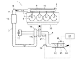
- FIG. 1 is a schematic explanatory diagram of an internal combustion engine according to an embodiment of the present disclosure.
- FIG. 2 is an enlarged view of a main part of FIG.
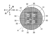
- FIG. 3 is a perspective view of the particulate filter.
- FIG. 4 is an enlarged view of a portion A in FIG.
- FIG. 5 is a diagram showing a state in which the reproduction interval is shortened.
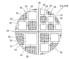
- FIG. 6 is an explanatory front view of the particulate filter showing the unburned amount of the particulate matter.
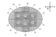
- FIG. 7 is a front view of a particulate filter according to another embodiment.
- the upstream side is also referred to as a front side and the downstream side is also referred to as a rear side for convenience of description.
- FIG. 1 is a schematic explanatory diagram of an internal combustion engine (engine) according to the present embodiment.
- the engine 1 is a multi-cylinder compression ignition type internal combustion engine mounted on a vehicle, that is, a diesel engine.
- a diesel engine mounted on a vehicle, that is, a diesel engine.
- the illustrated example shows an in-line four-cylinder engine, the cylinder arrangement type and the number of cylinders of the engine are arbitrary.
- the engine 1 includes an engine body 2, an intake passage 3 and an exhaust passage 4 connected to the engine body 2, and a fuel injection device 5.
- the engine body 2 includes structural parts such as a cylinder head, a cylinder block, and a crankcase, and movable parts housed therein, such as a piston, a crankshaft, and a valve.
- the fuel injection device 5 is a common rail type fuel injection device, and includes a fuel injection valve or injector 7 provided in each cylinder, and a common rail 8 connected to the injector 7.
- the injector 7 directly injects fuel into the cylinder 9.
- the common rail 8 stores fuel injected from the injector 7 in a high pressure state.
- the intake passage 3 is mainly defined by an intake manifold 10 connected to the engine body 2 (particularly, a cylinder head) and an intake pipe 11 connected to an upstream end of the intake manifold 10.
- the intake manifold 10 distributes and supplies the intake air sent from the intake pipe 11 to the intake ports of each cylinder.
- the intake pipe 11 is provided with an air cleaner 12, a compressor 14C of a turbocharger 14, an intercooler 15, and an electronically controlled intake throttle valve 16 in this order from the upstream side.
- the exhaust passage 4 is mainly defined by an exhaust manifold 20 connected to the engine body 2 (particularly, the cylinder head) and an exhaust pipe 21 arranged downstream of the exhaust manifold 20.
- the exhaust manifold 20 collects the exhaust gas sent from the exhaust port of each cylinder.
- a turbine 14T of the turbocharger 14 is provided between the exhaust pipe 21 or between the exhaust manifold 20 and the exhaust pipe 21.
- An oxidation catalyst 22 and a particulate filter (hereinafter, referred to as "DPF") 23 are provided in the exhaust pipe 21 downstream of the turbine 14T in order from the upstream side.
- the oxidation catalyst 22 and the DPF 23 are formed in a columnar shape having substantially the same diameter.
- the oxidation catalyst 22 and the DPF 23 are arranged coaxially in the canning case 24 with a small gap therebetween.
- the outer peripheral surfaces of the oxidation catalyst 22 and the DPF 23 are held by the canning case 24 via the mat 25.
- the canning case 24 is connected to a differential pressure sensor 26 that detects a differential pressure between the inlet and the outlet of the DFP 23.
- the differential pressure sensor 26 is connected to the control device 27.
- the differential pressure sensor 26 transmits the differential pressure information to the control device 27 as an electric signal.
- An exhaust pipe injection nozzle 28 is provided in the exhaust pipe 21 on the upstream side of the canning case 24.
- the exhaust pipe injection nozzle 28 injects fuel containing hydrocarbon (HC) into the exhaust pipe 21 according to a command from the control device 27.
- HC hydrocarbon
- the oxidation catalyst 22 oxidizes and purifies unburned components (hydrocarbon HC and carbon monoxide CO) in the exhaust gas, heats and raises the temperature of the exhaust gas by the reaction heat at this time, and removes NO in the exhaust gas. It is oxidized to NO 2.
- the DPF 23 collects and removes particulate matter (PM: Particulate Matter) contained in the exhaust gas.
- the DPF 23 is a so-called wall flow type.
- the DPF 23 is made of silicon carbide.
- the DPF 23 is a so-called continuous regeneration type DPF with a catalyst in which a noble metal such as Pt is supported on the inner wall.
- the noble metal oxidizes and combusts HC in the exhaust gas supplied to the DPF 23 by its catalytic action. With this combustion, PM deposited in the DPF 23 is burned and removed.
- the filter regeneration (PM removal by combustion) of the DPF 23 is performed by the filter regeneration control.
- the filter regeneration control when the amount of accumulated PM in the DPF 23 exceeds a predetermined amount, forcible regeneration control that forcibly burns and removes the accumulated PM to recover the PM collecting ability is given. Whether the PM accumulation amount has exceeded the predetermined amount is determined based on the differential pressure information transmitted from the differential pressure sensor 26 to the control device 27.
- the combustion removal of the deposited PM is performed by injecting fuel from the exhaust pipe injection nozzle 28 into the exhaust pipe 21. This injection enriches the exhaust air-fuel ratio.
- the HC in the exhaust gas reacts with the catalyst in the DPF 23, and the deposited heat is oxidized and burned by the reaction heat at this time. That is, when the differential pressure transmitted from the differential pressure sensor 26 exceeds a predetermined value, the control device 27 injects fuel from the exhaust pipe injection nozzle 28 to perform filter regeneration (forced regeneration) of the DPF 23. In addition, the filter regeneration control burns and removes accumulated PM when the traveling distance of the vehicle from the end of the previous filter regeneration control exceeds a predetermined value even when the PM accumulation amount does not exceed a predetermined value. There is also. Note that the filter regeneration control is not limited to this.
- the filter regeneration control may be such that post-injection from the injector 7 (in-cylinder injection performed in an expansion stroke after main injection) is performed instead of fuel injection from the exhaust pipe injection nozzle 28.
- the filter regeneration includes manual regeneration performed by a manual operation of a driver or the like irrespective of the differential pressure at the entrance and exit of the DFP 23 and the traveling distance of the vehicle. .
- FIG. 3 is a perspective view of the DPF 23 viewed from the upstream side in the exhaust gas flow.
- FIG. 4 is an enlarged view of a portion A in FIG. The hatching in FIG. 4 indicates the sealing of the cell 32.
- the upstream side of the DPF 23 is defined as the front side, and the downstream side is defined as the rear side.
- the DPF 23 is configured by providing a plurality of segments 29, 30, 31 adjacently and in parallel.
- the segments 29, 30, and 31 are formed in a honeycomb shape having a plurality of cells 32, and are formed by alternately closing the openings at both ends of the cells 32 in a checkered manner.
- the DPF 23 is produced by manufacturing a plurality of segments 29, 30, 31 having a rectangular cross section, bonding a plurality of these segments 29, 30, 31 in parallel, and shaving the outer surface to match the shape of the canning case 24. .
- the canning case 24 and the DPF 23 are formed in a circular cross section.
- the adhesive is made of, for example, silicon carbide. The surface where the segments 29, 30, and 31 are adhered hardly passes the exhaust gas, and has no function of collecting PM in the exhaust gas.
- the DPF 23 is configured by combining a plurality of types of segments 29, 30, and 31 having different densities of the cells 32 (hereinafter, referred to as “cell densities”).
- cell densities In the center of the DPF 23, the segment 29 having the highest cell density among the plurality of types of segments 29, 30, 31 is arranged. Segments 30 and 31 having a lower cell density than the central portion are arranged on the outer peripheral portion of the DPF 23.
- the segments 30 and 31 arranged on the outer periphery of the DPF 23 are set such that the cell density becomes lower as the area of the end face becomes smaller. Thereby, the gas flowing to the segments 30 and 31 can be increased at a position where PM is likely to remain unburned during filter regeneration. In addition, a decrease in the temperature of the segments 30 and 31 in the outer peripheral portion due to heat transfer to the canning case 24 can be suppressed.
- the DPF 23 is configured by combining three types (a plurality of types) of segments 29, 30, and 31. As shown in FIGS. 3 and 4, the DPF 23 includes a high-density segment 29, a medium-density segment 30 whose cell density is lower than the high-density segment 29, and a low-density segment 31 whose cell density is lower than the medium-density segment 30. .
- the high-density segment 29 is set to a cell density similar to that of a conventional DPF of the same type.
- the cell densities of the medium-density segment 30 and the low-density segment 31 are determined by experiments, simulations, and the like so that the regeneration performance (reproducibility without burning), PM trapping performance, and resistance to temperature changes during filter regeneration are optimized. It is determined.
- the central part of the DPF 23 is composed of a set of two high-density segments 29 vertically and horizontally.
- the outer peripheral portion at a position where the area of the end face is relatively large that is, the outer peripheral portion at a position adjacent to each of the upper, lower, left, and right surfaces of the set of the high-density segments 29 is constituted by the medium density segments 30.
- the outer peripheral portion at the position where the area of the end face is relatively small, that is, at the position adjacent to the set of the high-density segments 29 in the diagonal direction is constituted by the low-density segments 31.
- the control device 27 acquires the differential pressure information from the differential pressure sensor 26 at a predetermined cycle and determines whether or not the differential pressure has exceeded a predetermined value. Then, when the differential pressure exceeds the predetermined value, the control device 27 injects fuel from the exhaust pipe injection nozzle 28 to cause the DPF 23 to perform filter regeneration (forced regeneration).
- FIG. 5 is a graph showing the relationship between the PM accumulation weight and the differential pressure in the conventional DPF and the traveling distance.
- the solid line indicates the PM accumulation weight
- the one-dot chain line indicates the differential pressure detected by the differential pressure sensor 26.
- the vertical axis represents the PM deposition weight and the differential pressure
- the horizontal axis represents the traveling distance.
- the cell density of the segments 30 and 31 arranged on the outer peripheral portion is set lower than the cell density of the segment 29 arranged on the central portion. Therefore, the flow rate of the exhaust gas at the outer peripheral portion of the DPF 23 can be made larger than that of the conventional DPF. In addition, it is possible to suppress a decrease in the temperature of the segments 30 and 31 arranged on the outer peripheral portion of the DPF 23. For this reason, it is possible to eliminate or suppress the unburned PM remaining in the outer peripheral portion that occurs when the conventional DPF is regenerated by the filter.
- FIG. 6 is an explanatory diagram showing an example of the unburned amount at the time of filter regeneration in the DPF 50 having a uniform cell density.
- the DPF 50 is created for an experiment, and is formed by imitating the DPF 23 according to the present embodiment.
- “A”, “b”, and “c” in the figure indicate the unburned amount (g / L).
- the relationship between a, b, and c is a ⁇ b ⁇ c.
- the segment 51 having a smaller end face area tends to burn more PM.
- the segments 30 and 31 arranged on the outer peripheral portion are set such that the cell density decreases as the area of the end face decreases.
- the outer peripheral portion at a position where the cross-sectional area of the end face is small and a large amount of PM tends to remain unburned is constituted by the low-density segments 31.
- the outer peripheral portion at the position where the cross-sectional area of the end surface is large and the unburned PM remains relatively small is constituted by the medium density segment 30. This prevents or suppresses the cell density from being unnecessarily lowered, and prevents or suppresses a decrease in PM trapping performance. Then, the balance between the PM collection performance and the regeneration performance can be optimized.
- the types of the segments 30 and 31 may be appropriately changed according to the PM remaining amount.
- the unburned amount of PM in the segment located on the outer peripheral portion is measured in advance for each position.
- the cell density of the segments 30 and 31 located at the outer periphery is set lower than the cell density of the segment 29 located at the center.
- the segments 30 and 31 arranged on the outer peripheral portion are set such that the cell density decreases as the area of the end face decreases.
- the segments 30 and 31 arranged on the outer periphery may be set so that the cell density becomes lower as the amount of unburned PM becomes larger.
- the flow rate of the oxidation catalyst 22 at the outer peripheral portion is smaller than that at the center side, and the outer peripheral portion of the oxidation catalyst 22 is easily clogged with PM.
- the DPF 23 according to the present embodiment has a larger flow rate at the outer periphery than the conventional DPF. For this reason, the DPF 23 according to the present embodiment can satisfactorily distribute exhaust gas to the outer peripheral portion of the oxidation catalyst 22 even in a state where the DPF 23 is housed in the same canning case 24 as the oxidation catalyst 22. Further, clogging of PM in the outer peripheral portion of the oxidation catalyst 22 can be improved.
- the DPF 23 is formed to have a circular cross section, it is not limited to this. As shown in FIG. 7, for example, the DPF 40 may be formed to have an elliptical cross section. Further, the segments 30, 31, 41 may be arranged on the outer peripheral portion of the DPF 40 such that the cell density becomes lower as the position becomes farther from the center O of the DPF 40.
- the DPF 40 is configured by combining four types of segments 29, 30, 31, and 41.
- the DPF 40 is configured by combining the high-density segment 29, the medium-density segment 30, the low-density segment 31, and the ultra-low-density segment 41.
- the cell density of the ultra low density segment 41 is set lower than that of the low density segment 31.
- the high-density segment 29 is arranged at the center of the DPF 40.
- the central portion here is a position where the entire outer peripheral surface is surrounded by the other segments 30, 31, 41.
- a total of six high-density segments 29 are arranged at a position facing the center O of the DPF 40 and at a position adjacent to this position in the long radius direction (left-right direction).
- the long radius direction is a direction based on an ellipse which is an end face shape of the DPF.
- the medium density segment 30 is arranged at a position closest to the center O of the DPF 40 among the positions of the outer peripheral portion. Specifically, the middle density segment 30 is disposed at a position adjacent to the upper surface and the lower surface of the upper and lower high density segments 29 located at the center in the left-right direction among the six high density segments 29 forming the central portion. You.
- the low-density segment 31 is disposed at a position where the distance from the center O of the DPF 40 is medium among the positions of the outer peripheral portion.
- the position where the distance from the center O is medium is a position where the distance from the center O of the DPF 40 is not the maximum and not the minimum.
- the low-density segments 31 are arranged at positions adjacent to the left and right surfaces of the medium-density segment 30. Further, the low-density segments 31 are also arranged at positions adjacent to the left and right surfaces of the set of the high-density segments 29.
- the ultra-low-density segment 41 is located at a position farthest from the center O of the DPF 40 among the outer peripheral positions. Specifically, the ultra-low-density segments 41 are arranged at positions diagonally adjacent to the set of the high-density segments 29.
- the segments 30, 31, 41 are arranged such that the farther from the center O of the DPF 40, the lower the cell density.
- the outermost portion farthest from the center O of the DPF 40 and in which many PMs are likely to remain unburned is constituted by the ultra-low density segments 41.
- the outer peripheral portion which is closer to the center O of the DPF 40 than the ultra-low-density segment 41 and has less unburned PM than the ultra-low-density segment 41, is constituted by a medium-density segment 30 and a low-density segment 31. This prevents or suppresses the cell density from being unnecessarily lowered, and prevents or suppresses a decrease in PM trapping performance. Then, the balance between the PM collection performance and the regeneration performance can be optimized.
Landscapes
- Chemical & Material Sciences (AREA)
- Chemical Kinetics & Catalysis (AREA)
- Engineering & Computer Science (AREA)
- Physics & Mathematics (AREA)
- Geometry (AREA)
- Ceramic Engineering (AREA)
- Inorganic Chemistry (AREA)
- Mechanical Engineering (AREA)
- Combustion & Propulsion (AREA)
- General Engineering & Computer Science (AREA)
- Geology (AREA)
- Life Sciences & Earth Sciences (AREA)
- Health & Medical Sciences (AREA)
- Toxicology (AREA)
- Processes For Solid Components From Exhaust (AREA)
- Exhaust Gas After Treatment (AREA)
- Filtering Materials (AREA)
- Filtering Of Dispersed Particles In Gases (AREA)
Abstract
パティキュレートフィルタ23は、複数のセル32を有するハニカム形状のセグメント29、30、31を複数並列に設けて構成される。外周部に配置されるセグメント30、31のセルの密度は、中央部に配置されるセグメント29のセルの密度より低く設定される。また、外周部に配置されるセグメント30、31は、端面の面積が小さいほどセル32の密度が低くなるように設定される。
Description
本開示はパティキュレートフィルタ及びその製造方法に関する。
パティキュレートフィルタは、排気中に含まれる粒子状物質(PM: Particulate Matter)を捕集する。
このため、粒子状物質が堆積したパティキュレートフィルタは、その粒子状物質を燃焼させる等してフィルタ再生を行う必要がある。
しかし、パティキュレートフィルタには、フィルタ再生時に粒子状物質の燃え残りが生じるおそれがある。このため、繰り返しフィルタ再生されることでパティキュレートフィルタが徐々に詰まり、再生インターバルが短縮する場合がある。特に粒子状物質の燃え残りは、パティキュレートフィルタの外周部で生じる傾向がある。
そこで本開示は、かかる事情に鑑みて創案され、その目的は、フィルタ再生時における粒子状物質の燃え残りを抑制することができるパティキュレートフィルタ及びその製造方法を提供することにある。
本開示の一の態様によれば、
複数のセルを有するハニカム形状のセグメントを複数並列に設けて構成されたパティキュレートフィルタであって、
外周部に配置される前記セグメントのセルの密度は、中央部に配置される前記セグメントのセルの密度より低く設定され、
外周部に配置される前記セグメントは、端面の面積が小さいほど前記セルの密度が低くなるように設定された
ことを特徴とするパティキュレートフィルタが提供される。
複数のセルを有するハニカム形状のセグメントを複数並列に設けて構成されたパティキュレートフィルタであって、
外周部に配置される前記セグメントのセルの密度は、中央部に配置される前記セグメントのセルの密度より低く設定され、
外周部に配置される前記セグメントは、端面の面積が小さいほど前記セルの密度が低くなるように設定された
ことを特徴とするパティキュレートフィルタが提供される。
好ましくは、外周部に配置される前記セグメントは、前記パティキュレートフィルタの中心から遠いほど前記セルの密度が低くなるように設定される。
好ましくは、前記セグメントがシリコンカーバイトで構成される。
また、複数のセルを有するハニカム形状のセグメントを複数並列に設けて構成されたパティキュレートフィルタの製造方法であって、
外周部に配置されるセグメントにおける粒子状物質の燃え残り量をその位置毎に予め測定し、
外周部に配置される前記セグメントのセルの密度を、中央部に配置される前記セグメントのセルの密度より低く設定し、
外周部に配置される前記セグメントを、端面の面積が小さいほど前記セルの密度が低くなるように設定し、
外周部に配置される前記セグメントのセルの密度を、前記粒子状物質の燃え残り量が多い位置ほど低く設定する。
外周部に配置されるセグメントにおける粒子状物質の燃え残り量をその位置毎に予め測定し、
外周部に配置される前記セグメントのセルの密度を、中央部に配置される前記セグメントのセルの密度より低く設定し、
外周部に配置される前記セグメントを、端面の面積が小さいほど前記セルの密度が低くなるように設定し、
外周部に配置される前記セグメントのセルの密度を、前記粒子状物質の燃え残り量が多い位置ほど低く設定する。
上記の態様によれば、フィルタ再生時における粒子状物質の燃え残りを抑制することができる。
以下、添付図面を参照して本開示の実施形態を説明する。なお、後述する実施の形態では、説明の便宜のため上流側を前方ともいい、下流側を後方ともいう。
[第1実施形態]
図1は、本実施形態に係る内燃機関(エンジン)の概略説明図である。エンジン1は、車両に搭載された多気筒の圧縮着火式内燃機関、すなわちディーゼルエンジンである。図示例は直列4気筒エンジンを示すが、エンジンのシリンダ配置形式、気筒数等は任意である。
図1は、本実施形態に係る内燃機関(エンジン)の概略説明図である。エンジン1は、車両に搭載された多気筒の圧縮着火式内燃機関、すなわちディーゼルエンジンである。図示例は直列4気筒エンジンを示すが、エンジンのシリンダ配置形式、気筒数等は任意である。
エンジン1は、エンジン本体2と、エンジン本体2に接続された吸気通路3および排気通路4と、燃料噴射装置5とを備える。エンジン本体2は、シリンダヘッド、シリンダブロック、クランクケース等の構造部品と、その内部に収容されたピストン、クランクシャフト、バルブ等の可動部品とを含む。
燃料噴射装置5は、コモンレール式燃料噴射装置からなり、各気筒に設けられた燃料噴射弁すなわちインジェクタ7と、インジェクタ7に接続されたコモンレール8とを備える。インジェクタ7は、シリンダ9内に燃料を直接噴射する。コモンレール8は、インジェクタ7から噴射される燃料を高圧状態で貯留する。
吸気通路3は、エンジン本体2(特にシリンダヘッド)に接続された吸気マニホールド10と、吸気マニホールド10の上流端に接続された吸気管11とにより主に画成される。吸気マニホールド10は、吸気管11から送られてきた吸気を各気筒の吸気ポートに分配供給する。吸気管11には、上流側から順に、エアクリーナ12、ターボチャージャ14のコンプレッサ14C、インタークーラ15、および電子制御式の吸気スロットルバルブ16が設けられる。
排気通路4は、エンジン本体2(特にシリンダヘッド)に接続された排気マニホールド20と、排気マニホールド20の下流側に配置された排気管21とにより主に画成される。排気マニホールド20は、各気筒の排気ポートから送られてきた排気ガスを集合させる。排気管21、もしくは排気マニホールド20と排気管21の間には、ターボチャージャ14のタービン14Tが設けられる。タービン14Tより下流側の排気管21には、上流側から順に、酸化触媒22及びパティキュレートフィルタ(以下「DPF」という)23が設けられる。
図2に示すように、酸化触媒22及びDPF23は、ほぼ同径の円柱状に形成される。酸化触媒22及びDPF23は、キャニングケース24内に同軸に、かつ、微小な隙間を隔てて配置される。また、酸化触媒22及びDPF23の外周面は、マット25を介してキャニングケース24に保持される。キャニングケース24には、DFP23の入口及び出口の差圧を検出する差圧センサ26が接続される。差圧センサ26は、制御装置27に接続されている。差圧センサ26は、制御装置27に差圧情報を電気信号として伝達する。また、キャニングケース24より上流側の排気管21には、排気管噴射ノズル28が設けられる。排気管噴射ノズル28は、制御装置27からの命令に応じて排気管21内に炭化水素(HC)を含む燃料を噴射する。
酸化触媒22は、排気ガス中の未燃成分(炭化水素HCおよび一酸化炭素CO)を酸化して浄化すると共に、このときの反応熱で排気ガスを加熱昇温し、また排気中のNOをNO2に酸化する。
DPF23は、排気中に含まれる粒子状物質(PM: Particulate Matter)を捕集して除去する。DPF23は、所謂ウォールフロータイプである。DPF23は、シリコンカーバイトで構成される。
またDPF23は、その内壁にPt等の貴金属を担持させた所謂連続再生式の触媒付きDPFからなる。前記貴金属は、その触媒作用により、DPF23に供給された排気中のHCを酸化、燃焼させる。この燃焼に伴ってDPF23内に堆積しているPMは燃焼除去される。
また、DPF23は、フィルタ再生制御によってフィルタ再生(PMの燃焼除去)が行われる。フィルタ再生制御の一例として、DPF23におけるPM堆積量が所定量を超えたとき、その堆積PMを強制的に燃焼除去してPM捕集能を回復させる強制再生制御が挙げられる。PM堆積量が所定量を超えたか否かは、差圧センサ26から制御装置27に伝達される差圧情報に基づいて判断される。堆積PMの燃焼除去は、排気管噴射ノズル28から排気管21内に燃料を噴射することで行われる。この噴射により、排気空燃比がリッチ化される。すると排気中のHCがDPF23内の触媒と反応し、このときの反応熱で堆積PMが酸化、燃焼させられる。すなわち、制御装置27は、差圧センサ26から伝達される差圧が所定値を超えたとき、排気管噴射ノズル28から燃料を噴射してDPF23をフィルタ再生(強制再生)する。また、フィルタ再生制御には、PM堆積量が所定値を超えない状態であっても前回のフィルタ再生制御終了時からの車両の走行距離が所定値を超えたとき、堆積PMを燃焼除去するものもある。なお、フィルタ再生制御は、これに限るものではない。例えばフィルタ再生制御は、排気管噴射ノズル28からの燃料噴射に替えて、インジェクタ7からのポスト噴射(メイン噴射の後の膨張行程で行う筒内噴射)を行うものであってもよい。また、フィルタ再生には、上述したフィルタ再生制御(自動再生)の他、DFP23の入口及び出口の差圧や車両の走行距離に関わらず、運転者等の手動操作により実行される手動再生もある。
図3はDPF23を排ガス流における上流側から視た斜視図である。図4は図3のA部を拡大した拡大図である。図4中の網掛けは、セル32の目封じを表す。説明の便宜上、DPF23の上流側を前方とし、下流側を後方とする。
図3に示すように、DPF23は、複数のセグメント29、30、31を隣接させて且つ並列に設けて構成される。セグメント29、30、31は、複数のセル32を有するハニカム形状に形成されると共に、セル32の両端開口を互い違いに市松状に閉塞して形成される。DPF23は、断面矩形状のセグメント29、30、31を複数製造し、これらセグメント29、30、31を複数並列に接着し、その外面をキャニングケース24の形状に合わせるように削ることで作成される。キャニングケース24及びDPF23は、断面円形に形成される。接着材は、例えば、シリコンカーバイトで構成される。セグメント29、30、31同士が接着された面は、排ガスをほとんど通さず、排ガス中のPMを捕集する機能を有しない。
また、DPF23は、セル32の密度(以下、「セル密度」という)が異なる複数種類のセグメント29、30、31を組み合わせて構成される。DPF23の中央部には、これら複数種類のセグメント29、30、31のうち、最もセル密度が高いセグメント29が配置される。DPF23の外周部には、中央部よりもセル密度が低いセグメント30、31が配置される。
また、DPF23の外周部に配置されるセグメント30、31は、端面の面積が小さくなる位置ほどセル密度が低くなるように設定される。これにより、フィルタ再生時にPMが燃え残り易い位置ほどセグメント30、31に流れるガスを増やすことができる。そして、キャニングケース24への伝熱による外周部のセグメント30、31の温度低下を抑制することができる。
本実施の形態において、DPF23は、3種類(複数種類)のセグメント29、30、31を組み合わせて構成される。図3及び図4に示すように、DPF23は、高密度セグメント29と、セル密度が高密度セグメント29より低い中密度セグメント30と、セル密度が中密度セグメント30より低い低密度セグメント31とを備える。高密度セグメント29は、従来の同型のDPFと同程度のセル密度に設定される。中密度セグメント30及び低密度セグメント31のセル密度は、実験、シミュレーション等によってフィルタ再生時の再生性能(燃え残りなく再生できる性能)、PM捕集性能及び温度変化に対する耐性等が最適となるように決定される。
DPF23の中央部は、縦横に2つずつの高密度セグメント29の組で構成される。DPF23の外周部のうち、端面の面積が比較的大きい位置、すなわち、高密度セグメント29の組の上下左右の各面に隣接する位置の外周部は、中密度セグメント30で構成される。そして、端面の面積が比較的小さい位置、すなわち、高密度セグメント29の組の対角線方向に隣接する位置の外周部は、低密度セグメント31で構成される。
次に本実施の形態の作用について述べる。
エンジン1が作動されるとエンジン本体2からの排ガスが排気管21に流れる。この後、排ガスは、酸化触媒22を経てDPF23に流れる。DPF23に流れた排ガスは、前端が解放されたセル32内に流入し、セル32間の隔壁33に形成された微細な細孔(図示せず)を通過して隣接するセル32内に流れる。このとき、PMは細孔を通過しない。このため、PMはセル32間の隔壁33に捕集される。またこのとき、セグメント29、30、31の隔壁33同士が接着されて形成される隔壁34には、通気性はない。
また、制御装置27は、所定の周期で差圧センサ26から差圧情報を取得し、差圧が所定値を超えたか否かを判断する。そして、制御装置27は、差圧が所定値を超える場合、排気管噴射ノズル28から燃料を噴射し、DPF23をフィルタ再生(強制再生)させる。
ところで、従来のDPF(図示せず)は、中央部に多くの排ガスが流れ、外周部に流れる排ガスは少ない。また、DPFの外周部はキャニングケース24に近接されている。このため、DPFの外周部はキャニングケース24への伝熱により冷えやすい。このため、従来のDPFでは、フィルタ再生時に中央部より外周部の温度が低くなり易く、外周部でPMの燃え残りが発生し易い。
図5は、従来のDPFにおけるPM堆積重量及び差圧と走行距離との関係を表すグラフである。実線はPM堆積重量を示し、一点鎖線は差圧センサ26で検出される差圧を示す。縦軸はPM堆積重量及び差圧であり、横軸は走行距離である。図示するように、差圧が所定値を超える度に差圧及びPM堆積重量が急激に落ちている。これは、フィルタ再生制御によるものである。すなわち、差圧が所定値を超える度に燃料噴射が行われてDPFのフィルタ再生(強制再生)が行われた結果である。また、PM堆積重量の再生直後の初期値は、フィルタ再生を繰り返すことで増加する傾向がある。すなわち、フィルタ再生で燃え残ったPMは累積的に溜まっていく。
そこで、本実施の形態に係るDPF23では、中央部に配置されるセグメント29より外周部に配置されるセグメント30、31のセル密度が低く設定される。このため、DPF23の外周部において排ガスの流量を従来のDPFより大きくすることができる。そして、DPF23の外周部に配置されるセグメント30、31の温度低下を抑えることができる。このため、従来のDPFをフィルタ再生したときに発生する外周部におけるPMの燃え残りを解消又は抑制することができる。
また、従来のDPFには、PMの燃え残りが非常に発生しやすい外周部の位置と、そうでない外周部の位置とがある。
図6は、セル密度が均一に形成されたDPF50におけるフィルタ再生時の燃え残り量の一例を示す説明図である。DPF50は、実験用に作成されたものであり、本実施の形態に係るDPF23を模して形成される。図中のa、b、cは、燃え残り量(g/L)を示す。a、b、cの関係は、a<b<cである。図示するように、端面の面積が小さいセグメント51ほどPMが多く燃え残る傾向がある。
そこで、本実施の形態では、外周部に配置されるセグメント30、31は、端面の面積が小さくなる位置ほどセル密度が低くなるように設定される。すなわち、端面の断面積が小さく、多くのPMが燃え残り易い位置の外周部は、低密度セグメント31で構成される。これにより、PMの燃え残りが防止又は抑制される。またその反面、端面の断面積が大きく、PMの燃え残りが比較的少ない位置の外周部は、中密度セグメント30で構成される。これにより、必要以上にセル密度が低くなることが防止又は抑制され、PM捕集性能の低下が防止又は抑制される。そして、PM捕集性能と再生性能とのバランスを最適化できる。
なお、キャニングケース24が配置される位置等の条件によっては、端面の面積が同じであるにもかかわらず、PMの燃え残り量に差が生じる場合も考えられる。このような場合、PMの燃え残り量に応じて適宜セグメント30、31の種類を変更するとよい。具体的な方法としては、まず、外周部に位置されるセグメントにおけるPMの燃え残り量をその位置毎に予め測定する。次に、外周部に位置されるセグメント30、31のセル密度を、中央部に位置されるセグメント29のセル密度より低く設定する。そして、外周部に配置されるセグメント30、31を、端面の面積が小さいほどセル密度が低くなるように設定する。そしてさらに、外周部に配置されるセグメント30、31は、PMの燃え残り量が多い位置ほどセル密度が低くなるように設定されるとよい。
また、従来のDPFを酸化触媒22と同一のキャニングケース24に収容した場合、酸化触媒22においても中心側より外周部の流量が小さくなり、酸化触媒22の外周部にPMが詰まり易い。しかし、本実施の形態に係るDPF23は外周部の流量が従来のDPFより大きい。このため、本実施の形態に係るDPF23は、酸化触媒22と同一のキャニングケース24に収容された状態であっても、酸化触媒22の外周部に排ガスを良好に流通させることができる。そして、酸化触媒22の外周部におけるPMの詰まりを改善できる。
[第2実施形態]
DPF23は断面円形に形成されるものとしたが、これに限るものではない。図7に示すように、例えばDPF40は断面楕円形に形成されてもよい。また、DPF40の外周部には、DPF40の中心Oから遠い位置ほどセル密度が低くなるようにセグメント30、31、41が配置されてもよい。
DPF23は断面円形に形成されるものとしたが、これに限るものではない。図7に示すように、例えばDPF40は断面楕円形に形成されてもよい。また、DPF40の外周部には、DPF40の中心Oから遠い位置ほどセル密度が低くなるようにセグメント30、31、41が配置されてもよい。
具体的には、本実施の形態において、DPF40は、4種類のセグメント29、30、31、41を組み合わせて構成される。DPF40は、高密度セグメント29と、中密度セグメント30と、低密度セグメント31と、超低密度セグメント41とを組み合わせて構成される。超低密度セグメント41は、低密度セグメント31よりセル密度を低く設定される。
高密度セグメント29は、DPF40の中央部に配置される。ここでいう中央部とは、外周面の全てを他のセグメント30、31、41に囲まれる位置である。具体的には、高密度セグメント29は、DPF40の中心Oに臨む位置と、この位置に長半径方向(左右方向)に隣接する位置とに計6個配置される。ここで長半径方向とは、DPFの端面形状である楕円を基準とする方向である。
中密度セグメント30は、外周部の位置のうち、DPF40の中心Oに最も近い位置に配置される。具体的には、中密度セグメント30は、中央部を構成する6個の高密度セグメント29のうち、左右方向の中央に位置する上下の高密度セグメント29の上面及び下面に隣接する位置に配置される。
低密度セグメント31は、外周部の位置のうち、DPF40の中心Oからの距離が中位となる位置に配置される。中心Oからの距離が中位となる位置とは、DPF40の中心Oからの距離が最大でなく、最小でない位置である。具体的には、低密度セグメント31は、中密度セグメント30の左右の各面に隣接する位置に配置される。またさらに、低密度セグメント31は、高密度セグメント29の組の左右の各面に隣接する位置にも配置される。
超低密度セグメント41は、外周部の位置のうち、DPF40の中心Oから最も遠い位置に配置される。具体的には、超低密度セグメント41は、高密度セグメント29の組に対し対角線方向に隣接する位置に配置される。
次に本実施の形態の作用について述べる。
本実施の形態では、DPF40の中心Oから遠い位置ほどセル密度が低くなるようにセグメント30、31、41が配置される。例えば、DPF40の中心Oから最も遠く、多くのPMが燃え残り易い最外周部は、超低密度セグメント41で構成される。これにより、PMの燃え残りが防止又は抑制される。またその反面、超低密度セグメント41よりDPF40の中心Oに近く、PMの燃え残りが超低密度セグメント41より少ない外周部は、中密度セグメント30及び低密度セグメント31で構成される。これにより、必要以上にセル密度が低くなることが防止又は抑制され、PM捕集性能の低下が防止又は抑制される。そして、PM捕集性能と再生性能とのバランスを最適化できる。
なお、前述の各実施形態の構成は、特に矛盾が無い限り、部分的にまたは全体的に組み合わせることが可能である。本開示の実施形態は前述の実施形態のみに限らず、特許請求の範囲によって規定される本開示の思想に包含されるあらゆる変形例や応用例、均等物が本開示に含まれる。従って本開示は、限定的に解釈されるべきではなく、本開示の思想の範囲内に帰属する他の任意の技術にも適用することが可能である。
本出願は、2018年09月07日付で出願された日本国特許出願(特願2018-167881)に基づくものであり、その内容はここに参照として取り込まれる。
本開示によれば、フィルタ再生時における粒子状物質の燃え残りを抑制できるパティキュレートフィルタ及びその製造方法を提供するという点において有用である。
1 エンジン
2 エンジン本体
3 吸気通路
4 排気通路
5 燃料噴射装置
7 インジェクタ
8 コモンレール
9 シリンダ
10 吸気マニホールド
11 吸気管
12 エアクリーナ
14 ターボチャージャ
14C コンプレッサ
14T タービン
15 インタークーラ
16 吸気スロットルバルブ
20 排気マニホールド
21 排気管
22 酸化触媒
23 DPF(パティキュレートフィルタ)
24 キャニングケース
25 マット
26 差圧センサ
27 制御装置
28 排気管噴射ノズル
29 高密度セグメント(セグメント)
30 中密度セグメント(セグメント)
31 低密度セグメント(セグメント)
32 セル
33 隔壁
34 隔壁
40 DPF
41 超低密度セグメント(セグメント)
O 中心
2 エンジン本体
3 吸気通路
4 排気通路
5 燃料噴射装置
7 インジェクタ
8 コモンレール
9 シリンダ
10 吸気マニホールド
11 吸気管
12 エアクリーナ
14 ターボチャージャ
14C コンプレッサ
14T タービン
15 インタークーラ
16 吸気スロットルバルブ
20 排気マニホールド
21 排気管
22 酸化触媒
23 DPF(パティキュレートフィルタ)
24 キャニングケース
25 マット
26 差圧センサ
27 制御装置
28 排気管噴射ノズル
29 高密度セグメント(セグメント)
30 中密度セグメント(セグメント)
31 低密度セグメント(セグメント)
32 セル
33 隔壁
34 隔壁
40 DPF
41 超低密度セグメント(セグメント)
O 中心
Claims (4)
- 複数のセルを有するハニカム形状のセグメントを複数並列に設けて構成されたパティキュレートフィルタであって、
外周部に配置される前記セグメントのセルの密度は、中央部に配置される前記セグメントのセルの密度より低く設定され、
外周部に配置される前記セグメントは、端面の面積が小さいほど前記セルの密度が低くなるように設定された
ことを特徴とするパティキュレートフィルタ。 - 外周部に配置される前記セグメントは、前記パティキュレートフィルタの中心から遠いほど前記セルの密度が低くなるように設定された
請求項1に記載のパティキュレートフィルタ。 - 前記セグメントがシリコンカーバイトで構成された
請求項1又は2に記載のパティキュレートフィルタ。 - 複数のセルを有するハニカム形状のセグメントを複数並列に設けて構成されたパティキュレートフィルタの製造方法であって、
外周部に配置されるセグメントにおける粒子状物質の燃え残り量をその位置毎に予め測定し、
外周部に配置される前記セグメントのセルの密度を、中央部に配置される前記セグメントのセルの密度より低く設定し、
外周部に配置される前記セグメントを、端面の面積が小さいほど前記セルの密度が低くなるように設定し、
外周部に配置される前記セグメントのセルの密度を、前記粒子状物質の燃え残り量が多い位置ほど低く設定する
ことを特徴とするパティキュレートフィルタの製造方法。
Priority Applications (3)
| Application Number | Priority Date | Filing Date | Title |
|---|---|---|---|
| DE112019004492.3T DE112019004492T5 (de) | 2018-09-07 | 2019-09-05 | Partikelfilter und herstellungsverfahren für denselben |
| US17/274,089 US11446599B2 (en) | 2018-09-07 | 2019-09-05 | Particulate filter and manufacturing method for same |
| CN201980058048.9A CN112638497B (zh) | 2018-09-07 | 2019-09-05 | 颗粒过滤器及其制造方法 |
Applications Claiming Priority (2)
| Application Number | Priority Date | Filing Date | Title |
|---|---|---|---|
| JP2018-167881 | 2018-09-07 | ||
| JP2018167881A JP2020040004A (ja) | 2018-09-07 | 2018-09-07 | パティキュレートフィルタ及びその製造方法 |
Publications (1)
| Publication Number | Publication Date |
|---|---|
| WO2020050344A1 true WO2020050344A1 (ja) | 2020-03-12 |
Family
ID=69722591
Family Applications (1)
| Application Number | Title | Priority Date | Filing Date |
|---|---|---|---|
| PCT/JP2019/034897 Ceased WO2020050344A1 (ja) | 2018-09-07 | 2019-09-05 | パティキュレートフィルタ及びその製造方法 |
Country Status (5)
| Country | Link |
|---|---|
| US (1) | US11446599B2 (ja) |
| JP (1) | JP2020040004A (ja) |
| CN (1) | CN112638497B (ja) |
| DE (1) | DE112019004492T5 (ja) |
| WO (1) | WO2020050344A1 (ja) |
Citations (3)
| Publication number | Priority date | Publication date | Assignee | Title |
|---|---|---|---|---|
| JP2003275521A (ja) * | 2002-03-19 | 2003-09-30 | Ngk Insulators Ltd | ハニカムフィルター |
| WO2010113585A1 (ja) * | 2009-03-31 | 2010-10-07 | 日本碍子株式会社 | ハニカムフィルタ及びその製造方法 |
| JP2016029272A (ja) * | 2014-07-24 | 2016-03-03 | 株式会社デンソー | 排ガス浄化フィルタ |
Family Cites Families (15)
| Publication number | Priority date | Publication date | Assignee | Title |
|---|---|---|---|---|
| US7238217B2 (en) | 2004-04-23 | 2007-07-03 | Corning Incorporated | Diesel engine exhaust filters |
| US8273315B2 (en) * | 2010-08-09 | 2012-09-25 | Ford Global Technologies, Llc | Engine emission control system |
| JP5771541B2 (ja) | 2012-01-27 | 2015-09-02 | 株式会社デンソー | ハニカム構造体 |
| JP5892910B2 (ja) * | 2012-01-27 | 2016-03-23 | 株式会社デンソー | ハニカム構造体 |
| JP5892911B2 (ja) * | 2012-01-27 | 2016-03-23 | 株式会社デンソー | ハニカム構造体 |
| JP5708670B2 (ja) * | 2013-01-18 | 2015-04-30 | 株式会社デンソー | ハニカム構造体 |
| JP5888259B2 (ja) * | 2013-02-13 | 2016-03-16 | トヨタ自動車株式会社 | 触媒コンバーター |
| JP5939183B2 (ja) * | 2013-03-22 | 2016-06-22 | 株式会社デンソー | ハニカム構造体 |
| JP5821887B2 (ja) * | 2013-04-03 | 2015-11-24 | トヨタ自動車株式会社 | 触媒コンバーター |
| JP6137151B2 (ja) * | 2014-03-26 | 2017-05-31 | 株式会社デンソー | ハニカム構造体 |
| JP6587565B2 (ja) * | 2016-03-17 | 2019-10-09 | 日本碍子株式会社 | ハニカム構造体 |
| JP6753179B2 (ja) | 2016-07-08 | 2020-09-09 | いすゞ自動車株式会社 | 酸化触媒、及び、排気ガス浄化システム |
| US11084199B2 (en) * | 2016-08-09 | 2021-08-10 | Ngk Insulators, Ltd. | Honeycomb structure forming die |
| US10688706B2 (en) * | 2016-08-09 | 2020-06-23 | Ngk Insulators, Ltd. | Honeycomb structure forming die |
| JP6767235B2 (ja) * | 2016-10-19 | 2020-10-14 | 日本碍子株式会社 | 目封止ハニカム構造体 |
-
2018
- 2018-09-07 JP JP2018167881A patent/JP2020040004A/ja active Pending
-
2019
- 2019-09-05 WO PCT/JP2019/034897 patent/WO2020050344A1/ja not_active Ceased
- 2019-09-05 CN CN201980058048.9A patent/CN112638497B/zh active Active
- 2019-09-05 DE DE112019004492.3T patent/DE112019004492T5/de active Pending
- 2019-09-05 US US17/274,089 patent/US11446599B2/en active Active
Patent Citations (3)
| Publication number | Priority date | Publication date | Assignee | Title |
|---|---|---|---|---|
| JP2003275521A (ja) * | 2002-03-19 | 2003-09-30 | Ngk Insulators Ltd | ハニカムフィルター |
| WO2010113585A1 (ja) * | 2009-03-31 | 2010-10-07 | 日本碍子株式会社 | ハニカムフィルタ及びその製造方法 |
| JP2016029272A (ja) * | 2014-07-24 | 2016-03-03 | 株式会社デンソー | 排ガス浄化フィルタ |
Also Published As
| Publication number | Publication date |
|---|---|
| US11446599B2 (en) | 2022-09-20 |
| JP2020040004A (ja) | 2020-03-19 |
| CN112638497B (zh) | 2022-09-23 |
| US20210331111A1 (en) | 2021-10-28 |
| CN112638497A (zh) | 2021-04-09 |
| DE112019004492T5 (de) | 2021-06-10 |
Similar Documents
| Publication | Publication Date | Title |
|---|---|---|
| CN102071992B (zh) | 针对汽油发动机的排气颗粒管理 | |
| US8833061B2 (en) | Method and device for regenerating a particle filter in a Y-exhaust gas system | |
| US20070044460A1 (en) | Electrical diesel particulate filter (DPF) regeneration | |
| JPH10176519A (ja) | ディーゼルエンジン用パティキュレートトラップ | |
| CN110185519B (zh) | 燃烧发动机的颗粒过滤器及制造这样的颗粒过滤器的方法 | |
| JP2004028030A (ja) | 内燃機関の排気浄化装置 | |
| US11446599B2 (en) | Particulate filter and manufacturing method for same | |
| KR20060136013A (ko) | 디젤엔진의 입자상물질 제거용 필터장치 | |
| KR20070000043A (ko) | 디젤엔진의 입자상물질 제거용 필터장치 | |
| JP3797224B2 (ja) | 内燃機関の排気浄化装置 | |
| JP2004251138A (ja) | エンジンの排気微粒子浄化用フィルタ装置、及びエンジンの排気微粒子浄化装置 | |
| JP6156228B2 (ja) | 排気ガス浄化装置 | |
| JP5534208B2 (ja) | 内燃機関の排気浄化装置 | |
| JP4407285B2 (ja) | 排気ガス浄化システム | |
| JP4692334B2 (ja) | 排気微粒子捕集用フィルタの再生制御装置 | |
| JP2005291062A (ja) | フィルタ装置及びこれを備えた排気ガス浄化装置 | |
| JP2002180818A (ja) | 内燃機関の排気ガス浄化装置 | |
| JP2003035126A (ja) | ディーゼルエンジンの排気浄化装置 | |
| JP5845869B2 (ja) | ディーゼルエンジンの排気ガス浄化方法及び排気ガス浄化システム | |
| JP5734573B2 (ja) | 排気浄化装置 | |
| JP2010270626A (ja) | ディーゼル機関の制御システム | |
| KR20200025777A (ko) | 배기 가스 필터 모듈 및 이를 구비한 배기 시스템 | |
| JP2016186234A (ja) | 排気浄化装置及び酸化触媒の再生方法 | |
| US20200408120A1 (en) | Control device for internal combustion engine | |
| GB2557323A (en) | Catalyst and partially plugged gasoline particulate filter combination |
Legal Events
| Date | Code | Title | Description |
|---|---|---|---|
| 121 | Ep: the epo has been informed by wipo that ep was designated in this application |
Ref document number: 19858107 Country of ref document: EP Kind code of ref document: A1 |
|
| 122 | Ep: pct application non-entry in european phase |
Ref document number: 19858107 Country of ref document: EP Kind code of ref document: A1 |