WO2020049936A1 - 極低温冷凍機 - Google Patents
極低温冷凍機 Download PDFInfo
- Publication number
- WO2020049936A1 WO2020049936A1 PCT/JP2019/031007 JP2019031007W WO2020049936A1 WO 2020049936 A1 WO2020049936 A1 WO 2020049936A1 JP 2019031007 W JP2019031007 W JP 2019031007W WO 2020049936 A1 WO2020049936 A1 WO 2020049936A1
- Authority
- WO
- WIPO (PCT)
- Prior art keywords
- displacer
- collar
- cylinder
- chamber
- cryogenic refrigerator
- Prior art date
Links
Images
Classifications
-
- F—MECHANICAL ENGINEERING; LIGHTING; HEATING; WEAPONS; BLASTING
- F25—REFRIGERATION OR COOLING; COMBINED HEATING AND REFRIGERATION SYSTEMS; HEAT PUMP SYSTEMS; MANUFACTURE OR STORAGE OF ICE; LIQUEFACTION SOLIDIFICATION OF GASES
- F25B—REFRIGERATION MACHINES, PLANTS OR SYSTEMS; COMBINED HEATING AND REFRIGERATION SYSTEMS; HEAT PUMP SYSTEMS
- F25B41/00—Fluid-circulation arrangements
- F25B41/20—Disposition of valves, e.g. of on-off valves or flow control valves
-
- F—MECHANICAL ENGINEERING; LIGHTING; HEATING; WEAPONS; BLASTING
- F25—REFRIGERATION OR COOLING; COMBINED HEATING AND REFRIGERATION SYSTEMS; HEAT PUMP SYSTEMS; MANUFACTURE OR STORAGE OF ICE; LIQUEFACTION SOLIDIFICATION OF GASES
- F25B—REFRIGERATION MACHINES, PLANTS OR SYSTEMS; COMBINED HEATING AND REFRIGERATION SYSTEMS; HEAT PUMP SYSTEMS
- F25B9/00—Compression machines, plants or systems, in which the refrigerant is air or other gas of low boiling point
- F25B9/14—Compression machines, plants or systems, in which the refrigerant is air or other gas of low boiling point characterised by the cycle used, e.g. Stirling cycle
-
- F—MECHANICAL ENGINEERING; LIGHTING; HEATING; WEAPONS; BLASTING
- F25—REFRIGERATION OR COOLING; COMBINED HEATING AND REFRIGERATION SYSTEMS; HEAT PUMP SYSTEMS; MANUFACTURE OR STORAGE OF ICE; LIQUEFACTION SOLIDIFICATION OF GASES
- F25B—REFRIGERATION MACHINES, PLANTS OR SYSTEMS; COMBINED HEATING AND REFRIGERATION SYSTEMS; HEAT PUMP SYSTEMS
- F25B2309/00—Gas cycle refrigeration machines
- F25B2309/14—Compression machines, plants or systems characterised by the cycle used
- F25B2309/1428—Control of a Stirling refrigeration machine
Definitions
- the present invention relates to a cryogenic refrigerator.
- the GM (Gifford-McMahon) refrigerator which is one of the representative examples of the cryogenic refrigerator, is roughly classified into two types, a motor-driven type and a gas-driven type, depending on the driving source of the displacer.
- a motor driven type a displacer is mechanically connected to a motor and driven by the motor.
- the gas drive type the displacer is driven by gas pressure.
- the present inventors have conducted intensive research on a gas-driven cryogenic refrigerator, and as a result, have come to recognize the following problems.
- the displacer moves until it interferes (eg, collides) with the cylinder end due to gas pressure. Interference can cause vibration and noise.
- a design referred to as a "collar bumper" may be employed.
- the gas-driven cryogenic refrigerator of the color bumper type when the displacer reaches the bottom dead center, a low-pressure sealed area is formed on one side of the collar, and the pressure difference with the high-pressure area on the other side of the collar is generated. Movement of the displacer towards top dead center may be impeded.
- One of the exemplary purposes of one embodiment of the present invention is to facilitate the movement of the displacer from bottom dead center to top dead center in a color bumper type gas driven cryogenic refrigerator.
- a cryogenic refrigerator includes a cylinder, a displacer disposed within the cylinder, the reciprocating motion driven by gas pressure, and a collar rigidly connected to the displacer to reciprocate with the displacer.
- a color chamber divided into an upper section and a lower section by a collar; a lower bumper provided in the lower section so as to reduce interference between the displacer and the cylinder when the displacer is at the bottom dead center;
- a communication passage formed in the collar or the color chamber so as to ensure communication between the upper compartment and the lower compartment when at the dead center.
- FIG. 13 is a diagram schematically illustrating a collar and a bumper according to another embodiment.
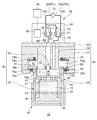
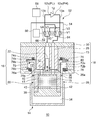
- FIGS. 1 and 2 are schematic diagrams showing a cryogenic refrigerator 10 according to an embodiment.
- the cryogenic refrigerator 10 is, for example, a gas-driven GM refrigerator.
- the cryogenic refrigerator 10 includes a compressor 12 for compressing a working gas (for example, helium gas) and a cold head 14 for cooling the working gas by adiabatic expansion.
- the compressor 12 has a compressor discharge port 12a and a compressor suction port 12b.
- the compressor discharge port 12a and the compressor suction port 12b function as a high pressure source and a low pressure source of the cryogenic refrigerator 10, respectively.
- the cold head 14 is also called an expander.
- the compressor 12 supplies a high pressure (PH) working gas to the cold head 14 from the compressor discharge port 12a.
- the cold head 14 is provided with a regenerator 15 for pre-cooling the working gas.
- the pre-cooled working gas is further cooled by expansion in the cold head 14.
- the working gas is collected at the compressor inlet 12b through the regenerator 15.
- the working gas cools the regenerator 15 when passing through the regenerator 15.
- the compressor 12 compresses the collected low-pressure (PL) working gas and supplies it to the cold head 14 again.
- the illustrated cold head 14 is a single-stage type. However, the cold head 14 may be a multi-stage.
- the cold head 14 includes an axial movable body 16 as a free piston driven by gas pressure, and a cold head housing 18 that is airtightly configured and houses the axial movable body 16.
- the cold head housing 18 supports the axially movable body 16 so as to be able to reciprocate in the axial direction, and is configured as a pressure vessel for working gas.
- the cold head 14 does not have a motor for driving the axially movable body 16 and a coupling mechanism (for example, a Scotch yoke mechanism).
- the axially movable body 16 includes a displacer 20 that can reciprocate in the axial direction (the vertical direction in FIG. 1, indicated by an arrow C), and a driving piston coaxially connected to the displacer 20 so as to drive the displacer 20 in the axial direction. 22.
- the drive piston 22 is rigidly connected to the displacer 20 so that the displacer 20 reciprocates in the axial direction integrally with the drive piston 22.
- the drive piston 22 has a smaller size than the displacer 20.
- the axial length of the drive piston 22 is shorter than that of the displacer 20, and the diameter of the drive piston 22 is also smaller than that of the displacer 20.
- the cold head housing 18 includes a displacer cylinder 26 that houses the displacer 20 and a piston cylinder 28 that houses the drive piston 22.
- the piston cylinder 28 is disposed coaxially with the displacer cylinder 26 and adjacent to the displacer cylinder 26 in the axial direction.
- the drive unit of the gas-driven cold head 14 includes a drive piston 22 and a piston cylinder 28.
- the volume of the piston cylinder 28 is smaller than that of the displacer cylinder 26.
- the axial length of the piston cylinder 28 is shorter than that of the displacer cylinder 26, and the diameter of the piston cylinder 28 is also smaller than that of the displacer cylinder 26.
- the axial reciprocation of the displacer 20 is guided by the displacer cylinder 26.
- the displacer 20 and the displacer cylinder 26 are each cylindrical members extending in the axial direction, and the inner diameter of the displacer cylinder 26 is equal to or slightly larger than the outer diameter of the displacer 20.
- axial reciprocation of the drive piston 22 is guided by a piston cylinder 28.
- the drive piston 22 and the piston cylinder 28 are each cylindrical members extending in the axial direction, and the inner diameter of the piston cylinder 28 matches or is slightly larger than the outer diameter of the drive piston 22.
- the axial stroke of the drive piston 22 is equal to the axial stroke of the displacer 20, and both move integrally over the entire stroke.
- the position of the drive piston 22 relative to the displacer 20 does not change during the axial reciprocation of the movable body 16.
- the first seal portion 32 is provided between the drive piston 22 and the piston cylinder 28.
- the first seal portion 32 is mounted on one of the drive piston 22 and the piston cylinder 28 and slides on the other of the drive piston 22 and the piston cylinder 28.
- the first seal portion 32 is formed of, for example, a seal member such as a slipper seal or an O-ring.
- the piston cylinder 28 is hermetically sealed with respect to the displacer cylinder 26 by the first seal portion 32. Since the first seal portion 32 is provided, there is no direct gas flow between the piston cylinder 28 and the displacer cylinder 26.
- the internal pressure of the piston cylinder 28 and the internal pressure of the displacer cylinder 26 can have different magnitudes.
- the displacer cylinder 26 is partitioned by the displacer 20 into an expansion chamber 34 and a room temperature chamber 36.
- the displacer 20 forms an expansion chamber 34 at one end in the axial direction with the displacer cylinder 26, and forms a room temperature chamber 36 with the displacer cylinder 26 at the other end in the axial direction.
- the room temperature chamber 36 can also be called a compression chamber.
- the cold head 14 is provided with a cooling stage 38 fixed to the displacer cylinder 26 so as to enclose the expansion chamber 34.
- the regenerator 15 is built in the displacer 20.
- the upper portion of the displacer 20 has an inlet channel 40 that connects the regenerator 15 to the room temperature chamber 36.
- the displacer 20 has an outlet flow path 42 in its cylindrical portion that connects the regenerator 15 to the expansion chamber 34.
- the outlet channel 42 may be provided in the lower lid of the displacer 20.
- the regenerator 15 includes an inlet retainer 41 inscribed in the upper lid and an outlet retainer 43 inscribed in the lower lid.
- the regenerator material may be, for example, a copper wire mesh.
- the retainer may be a wire mesh coarser than the cold storage material.
- the second seal portion 44 is provided between the displacer 20 and the displacer cylinder 26.
- the second seal portion 44 is, for example, a slipper seal, and is attached to a cylindrical portion or an upper lid portion of the displacer 20. Since the clearance between the displacer 20 and the displacer cylinder 26 is sealed by the second seal portion 44, there is no direct gas flow between the room temperature chamber 36 and the expansion chamber 34 (that is, the gas flow bypassing the regenerator 15).
- the working gas flows into the regenerator 15 from the room temperature chamber 36 through the inlet channel 40. More precisely, the working gas flows from the inlet passage 40 into the regenerator 15 through the inlet retainer 41. The working gas flows from the regenerator 15 into the expansion chamber 34 via the outlet retainer 43 and the outlet channel 42. When the working gas returns from the expansion chamber 34 to the room temperature chamber 36, it passes through the reverse route. That is, the working gas returns from the expansion chamber 34 to the room temperature chamber 36 through the outlet channel 42, the regenerator 15, and the inlet channel 40. The working gas that bypasses the regenerator 15 and flows through the clearance is blocked by the second seal portion 44.
- the cold head 14 is installed in the direction shown in the field where it is used. That is, the cold head 14 is installed vertically so that the displacer cylinder 26 is arranged vertically downward and the piston cylinder 28 is arranged vertically upward. As described above, when the cryogenic refrigerator 10 is installed in a posture in which the cooling stage 38 is directed downward in the vertical direction, the cryogenic refrigerator 10 has the highest refrigeration capacity. However, the arrangement of the cryogenic refrigerator 10 is not limited to this. Conversely, the cold head 14 may be installed in a posture in which the cooling stage 38 is directed vertically upward. Alternatively, the cold head 14 may be installed in a sideways or other orientation. The cold head 14 can be cooled even if it is installed in any posture.
- the end of the reciprocating stroke of the displacer 20 on the expansion chamber 34 side is called the bottom dead center of the displacer 20, and the end of the reciprocating stroke of the displacer 20 on the room temperature room 36 side is called the top dead center of the displacer 20.
- the movement of the displacer 20 toward the top dead center may be referred to as upward movement, and the movement of the displacer 20 toward the bottom dead center may be referred to as downward movement.
- these terms do not limit the attitude of the cold head 14.
- the expansion chamber 34 and the room temperature chamber 36 increase or decrease the volume complementarily. That is, when the displacer 20 moves down, the expansion chamber 34 becomes narrow and the room temperature chamber 36 becomes wide. The reverse is also true. Therefore, when the displacer 20 is located at the bottom dead center, the volume of the expansion chamber 34 is minimum (the volume of the room temperature chamber 36 is maximum). When the displacer 20 is located at the top dead center, the volume of the expansion chamber 34 becomes maximum (the volume of the room temperature chamber 36 becomes minimum).
- the cryogenic refrigerator 10 includes a working gas circuit 52 that connects the compressor 12 to the cold head 14.
- the working gas circuit 52 is configured to create a pressure difference between the piston cylinder 28 and the displacer cylinder 26 (ie, the expansion chamber 34 and / or the room temperature chamber 36). This pressure difference causes the axially movable body 16 to move in the axial direction. If the pressure of the displacer cylinder 26 with respect to the piston cylinder 28 is low, the drive piston 22 moves down, and accordingly, the displacer 20 also moves down. Conversely, if the pressure of the displacer cylinder 26 is high with respect to the piston cylinder 28, the drive piston 22 moves upward, and accordingly, the displacer 20 also moves upward.
- the working gas circuit 52 includes a valve section 54.
- the valve section 54 may be disposed adjacent to the piston cylinder 28 so as to be integrated with the cold head housing 18 and connected to the compressor 12 by piping.
- the valve portion 54 may be provided outside the cold head housing 18 and connected to the compressor 12 and the cold head 14 by piping.
- the valve section 54 includes an expansion chamber pressure switching valve (hereinafter, also referred to as a main pressure switching valve) 60 and a driving chamber pressure switching valve (hereinafter, also referred to as an auxiliary pressure switching valve) 62.
- the main pressure switching valve 60 has a main intake opening / closing valve V1 and a main exhaust opening / closing valve V2.
- the sub-pressure switching valve 62 has a sub-intake opening / closing valve V3 and a sub-exhaust opening / closing valve V4.
- the working gas circuit 52 includes a high-pressure line 13a and a low-pressure line 13b that connect the compressor 12 to the valve unit 54.
- the high-pressure line 13a extends from the compressor discharge port 12a, branches on the way, and is connected to the main intake opening / closing valve V1 and the auxiliary intake opening / closing valve V3.
- the low-pressure line 13b extends from the compressor inlet 12b, branches on the way, and is connected to the main exhaust valve V2 and the auxiliary exhaust valve V4.
- the working gas circuit 52 includes a main communication path 64 and a sub communication path 66 for connecting the cold head 14 to the valve section 54.
- the main communication passage 64 connects the displacer cylinder 26 to the main pressure switching valve 60.
- the main communication passage 64 extends from the room temperature chamber 36, branches on the way, and is connected to the main intake opening / closing valve V1 and the main exhaust opening / closing valve V2.
- the auxiliary communication passage 66 connects the piston cylinder 28 to the auxiliary pressure switching valve 62.
- the auxiliary communication passage 66 extends from the piston cylinder 28, branches off in the middle, and is connected to the auxiliary intake opening / closing valve V3 and the auxiliary exhaust opening / closing valve V4.
- the main pressure switching valve 60 is configured to selectively connect the compressor discharge port 12a or the compressor suction port 12b to the room temperature chamber 36 of the displacer cylinder 26.
- the main intake opening / closing valve V1 and the main exhaust opening / closing valve V2 are exclusively opened. That is, the simultaneous opening of the main intake opening / closing valve V1 and the main exhaust opening / closing valve V2 is prohibited.
- the main intake open / close valve V1 and the main exhaust open / close valve V2 may be temporarily closed together.
- the main exhaust opening / closing valve V2 when the main exhaust opening / closing valve V2 is open, the main intake opening / closing valve V1 is closed.
- the high-pressure PH working gas is expanded and decompressed in the expansion chamber 34.
- the working gas flows from the expansion chamber 34 to the room temperature chamber 36 through the regenerator 15.
- Working gas flows from the displacer cylinder 26 to the compressor suction port 12b through the main communication passage 64 and the low-pressure line 13b.
- the low-pressure PL working gas is recovered from the cold head 14 to the compressor 12.
- the main exhaust valve V2 When the main exhaust valve V2 is closed, the collection of the working gas from the expansion chamber 34 to the compressor 12 is stopped.
- the auxiliary pressure switching valve 62 is configured to selectively connect the compressor discharge port 12a or the compressor suction port 12b to the piston cylinder 28.
- the auxiliary pressure switching valve 62 is configured such that the auxiliary intake opening / closing valve V3 and the auxiliary exhaust opening / closing valve V4 are exclusively opened. That is, the simultaneous opening of the auxiliary intake opening / closing valve V3 and the auxiliary exhaust opening / closing valve V4 is prohibited. Note that the auxiliary intake opening / closing valve V3 and the auxiliary exhaust opening / closing valve V4 may be temporarily closed together.
- auxiliary exhaust opening / closing valve V4 when the auxiliary exhaust opening / closing valve V4 is open, the auxiliary intake opening / closing valve V3 is closed.
- Working gas is recovered from the piston cylinder 28 to the compressor suction port 12b through the auxiliary communication passage 66 and the low-pressure line 13b, and the pressure of the piston cylinder 28 is reduced to the low pressure PL.
- the sub exhaust valve V4 is closed, the collection of the working gas from the piston cylinder 28 to the compressor 12 is stopped.
- the main pressure switching valve 60 generates a periodic pressure fluctuation of the high pressure PH and the low pressure PL in the expansion chamber 34.
- the sub-pressure switching valve 62 generates periodic pressure fluctuations of the high pressure PH and the low pressure PL in the piston cylinder 28.
- the auxiliary pressure switching valve 62 is configured to control the pressure of the piston cylinder 28 so that the drive piston 22 drives the displacer 20 to reciprocate in the axial direction.
- the pressure fluctuations in the piston cylinder 28 are generated in the same cycle as the pressure fluctuations in the expansion chamber 34 and in substantially the opposite phase.
- the valve section 54 may take the form of a rotary valve.
- a group of valves (V1 to V4) are incorporated in the valve section 54 and are driven synchronously.
- the valve section 54 is configured such that the valves (V1 to V4) are appropriately switched by the rotational sliding of the valve disk (or the valve rotor) with respect to the valve body (or the valve stator).
- the group of valves (V1 to V4) are switched at the same cycle during the operation of the cryogenic refrigerator 10, whereby the four open / close valves (V1 to V4) change the open / close state periodically.
- the four open / close valves (V1 to V4) are opened / closed in different phases.
- the cryogenic refrigerator 10 may include a rotation drive source 56 connected to the valve unit 54 to rotate the valve unit 54.
- the rotation drive source 56 is mechanically connected to the valve unit 54.
- the rotation drive source 56 is, for example, a motor. However, the rotation drive source 56 is not mechanically connected to the axially movable body 16.
- the cryogenic refrigerator 10 may include a control unit 58 that controls the valve unit 54.
- the control unit 58 may control the rotation drive source 56.
- the group of valves (V1-V4) may take the form of a plurality of individually controllable valves.
- Each of the valves (V1 to V4) may be an electromagnetic on-off valve.
- the valves (V1 to V4) are electrically connected to the control unit 58 instead of providing the rotation drive source 56.
- the control unit 58 may control the opening and closing of each valve (V1 to V4).
- FIG. 1 shows a state where the displacer 20 is located at the bottom dead center
- FIG. 2 shows a state where the displacer 20 is located at the top dead center.
- the cold head 14 includes a collar 70 and a color chamber 72 divided into an upper section 72 a and a lower section 72 b by the collar 70.
- the collar 70 is rigidly connected to the displacer 20 so as to reciprocate with the displacer 20 and forms a part of the axially movable body 16. As described later, the reciprocating stroke of the collar 70 in the color chamber 72 determines the reciprocating stroke of the displacer 20.
- the displacer cylinder 26 includes a cylinder flange 26a that defines a cylinder upper opening.
- the cylinder flange 26a extends radially outward from the axial upper end of the displacer cylinder 26.
- the cold head housing 18 includes a top plate 30 and a sleeve 73.
- the piston cylinder 28 and the sleeve 73 are fixed to the top 30, and the valve unit 54 is mounted on the top 30.
- the cylinder flange 26a is connected to the top plate 30 via a sleeve 73.
- the sleeve 73 is arranged outside the piston cylinder 28 so as to surround the piston cylinder 28.
- the collar 70 includes a cylindrical main body 70a and a collar upper end 70b.
- the main body 70a has substantially the same outer diameter as the displacer 20, and extends upward from the room temperature room 36 side of the displacer 20.
- the inner diameter of the main body 70a is larger than the outer diameter of the piston cylinder 28.
- the collar upper end 70 b exists outside the outer diameter of the displacer 20.
- the color chamber 72 is divided into an upper section 72a and a lower section 72b by a collar upper end 70b.
- the color chamber 72 communicates with the room temperature chamber 36.
- the cold head 14 also includes an upper bumper 74 provided in the upper section 72a so as to reduce interference between the displacer 20 and the displacer cylinder 26 when the displacer 20 is at the top dead center.
- the upper bumper 74 is installed on the upper surface of the collar chamber 72, and has an upper cushioning member 74a and an upper retainer 74b.
- the upper bumper 74 is attached to the sleeve 73, for example.
- the upper cushioning member 74a is an annular member made of resin such as an O-ring, and is sandwiched between the upper surface of the collar chamber 72 and the upper retainer 74b.
- the upper retainer 74b is formed of, for example, a resin material. Note that the upper retainer 74b may not be provided.
- the upper bumper 74 contacts the collar 70 when the displacer 20 is located at the top dead center, and prevents the collision between the displacer 20 and the displacer cylinder 26 on the room temperature room 36 side. Collar upper end 70b engages upper bumper 74 in collar chamber 72 before displacer 20 strikes piston cylinder 28 as displacer 20 moves up. At this time, the upper end 70b of the collar contacts the upper retainer 74b, the upper cushioning material 74a is compressed, and the impact is absorbed.
- the cold head 14 includes a lower bumper 76 provided in the lower section 72b so as to reduce interference between the displacer 20 and the displacer cylinder 26 when the displacer 20 is at the bottom dead center.
- the lower bumper 76 is installed on the lower surface of the collar chamber 72, and has a lower buffer 76a and a lower retainer 76b.
- the lower bumper 76 is attached to, for example, the cylinder flange 26a.
- the lower bumper 76 may be attached to the sleeve 73.
- the lower cushioning member 76a is a resin-made annular member such as an O-ring, and is sandwiched between the lower surface of the collar chamber 72 and the lower retainer 76b.
- the lower retainer 76b is formed of, for example, a resin material. Note that the lower retainer 76b may not be provided.
- the lower bumper 76 contacts the collar 70 when the displacer 20 is located at the bottom dead center, and prevents the collision between the displacer 20 and the displacer cylinder 26 on the expansion chamber 34 side.
- the collar upper end 70b engages the lower bumper 76 in the collar chamber 72 before the displacer 20 collides with the displacer cylinder 26 on the expansion chamber 34 side when the displacer 20 moves down.
- the upper end 70b of the collar comes into contact with the lower retainer 76b, the lower cushioning material 76a is compressed, and the impact is absorbed.
- the upper section 72a communicates with the room temperature chamber 36.
- a first gap 78a is formed between the outer peripheral surface of the piston cylinder 28 and the inner peripheral surface of the collar 70, and the working gas can flow between the room temperature chamber 36 and the upper section 72a through the first gap 78a.
- the lower section 72b communicates with the upper section 72a.
- a second gap 78b is formed between the inner peripheral surface of the sleeve 73 and the outer peripheral surface of the collar upper end 70b, and the working gas can flow between the upper section 72a and the lower section 72b through the second gap 78b.
- the displacer 20 when the displacer 20 is located at the bottom dead center, the upper end 70b of the collar contacts the lower bumper 76, and the communication between the lower section 72b and the upper section 72a through the second gap 78b is shut off.
- the upper end 70b of the collar contacts the upper bumper 74, and the communication between the lower section 72b and the upper section 72a through the second gap 78b is shut off.
- the lower compartment 72b communicates with the room compartment 36 through the upper compartment 72a and operates between the room compartment 36 and the lower compartment 72b. Gas can flow. Further, since the lower section 72 b is sealed by the second seal portion 44, the lower section 72 b does not communicate with the expansion chamber 34.
- the cold head 14 also includes a communication path 80 that ensures communication between the upper section 72a and the lower section 72b when the displacer 20 is at the bottom dead center.
- the communication passage 80 is formed in the collar 70 such that the upper section 72a communicates with the lower section 72b when the upper end 70b of the collar is in contact with the lower bumper 76.
- the communication passage 80 is formed so as to penetrate the collar 70 (for example, the collar upper end 70b) from the upper section 72a to the lower section 72b, and it is sufficient that at least one communication path 80 is provided in the circumferential direction.
- the communication passage 80 is formed at the collar upper end 70b at a position radially inward with respect to the lower bumper 76. It is formed.
- the communication passage 80 may be formed so as to penetrate the main body 70 a of the collar 70.
- the first gap 78a, the second gap 78b, and the communication path 80 function as flow path resistance. Therefore, when the displacer 20 reciprocates, the upper section 72a and the lower section 72b can each generate a gas spring force. As the displacer 20 moves upward, the collar upper end 70b also moves upward, and the upper section 72a becomes narrower. At this time, the gas in the upper section 72a is compressed, and the pressure increases. The pressure in the upper section 72a acts downward on the upper surface of the collar upper end 70b. Thus, the upper section 72a generates a gas spring force that opposes the upward movement of the collar 70 and the displacer 20.
- the lower section 72b when the displacer 20 moves down, the lower section 72b generates a gas spring force that opposes the movement of the collar 70 and the displacer 20.
- the upper section 72a and the lower section 72b may be referred to as an upper gas spring chamber and a lower gas spring chamber, respectively.
- the gas spring force helps reduce vibration and noise that can occur when the collar 70 contacts the upper bumper 74 and the lower bumper 76.
- the operation of the cryogenic refrigerator 10 will be described.
- the main intake open / close valve V1 is opened, and the main exhaust open / close valve V2 is closed.
- Working gas is supplied from the compressor discharge port 12a to the displacer cylinder 26 of the cold head 14 through the main intake opening / closing valve V1, and the expansion chamber 34 and the room temperature chamber 36 are set to a high pressure PH.
- the exhaust from the piston cylinder 28 is performed simultaneously with the intake into the expansion chamber 34.
- the auxiliary intake opening / closing valve V3 is closed, and the auxiliary exhaust opening / closing valve V4 is opened.
- the working gas is discharged from the piston cylinder 28 to the compressor inlet 12b through the sub-exhaust opening / closing valve V4, and the pressure of the piston cylinder 28 is reduced to a low pressure PL.
- the driving force due to the differential pressure (PH-PL) between the piston cylinder 28 and the expansion chamber 34 acts on the driving piston 22 upward.
- the displacer 20 moves from the bottom dead center to the top dead center together with the drive piston 22.
- the volume of the expansion chamber 34 is increased and filled with the high-pressure gas.
- the collar 70 moves upward together with the displacer 20. Collar 70 contacts upper bumper 74 before displacer 20 collides with the hot end of displacer cylinder 26 (eg, piston cylinder 28). The upper cushioning material 74a is compressed, and the impact is absorbed. During the upward movement of the collar 70, the upper section 72a communicates with the room temperature chamber 36 through the first gap 78a, and the lower section 72b communicates with the upper section 72a through the second gap 78b and the communication passage 80. The lower compartment 72b is at a high pressure PH as in the room temperature chamber 36.
- the exhaust process of the cryogenic refrigerator 10 is started.
- the main exhaust open / close valve V2 is opened, and the main intake open / close valve V1 is closed.
- the high-pressure gas is expanded and cooled in the expansion chamber 34.
- the expanded gas is collected in the compressor inlet 12b through the room temperature chamber 36 while cooling the regenerator 15.
- the expansion chamber 34 and the room temperature chamber 36 have a low pressure PL.
- the intake to the piston cylinder 28 is performed.
- the sub exhaust valve V4 is closed, and the sub intake valve V3 is opened.
- Working gas is supplied from the compressor discharge port 12a to the piston cylinder 28 through the auxiliary intake opening / closing valve V3, and the pressure of the piston cylinder 28 is increased to a high pressure PH.
- the driving force due to the differential pressure (PH-PL) between the piston cylinder 28 and the expansion chamber 34 acts on the driving piston 22 in a downward direction.
- the displacer 20 moves from the top dead center to the bottom dead center together with the drive piston 22.
- the volume of the expansion chamber 34 is reduced and the low-pressure gas is discharged.
- the collar 70 moves down together with the displacer 20. Collar 70 contacts lower bumper 76 before displacer 20 collides with the cold end of displacer cylinder 26.
- the lower cushioning material 76a is compressed, and the impact is absorbed.
- the upper section 72a communicates with the room temperature chamber 36 through the first gap 78a
- the lower section 72b communicates with the upper section 72a through the second gap 78b and the communication passage 80.
- the lower compartment 72b is at a low pressure PL similarly to the room temperature chamber 36.
- the cryogenic refrigerator 10 cools the cooling stage 38 by repeating such a refrigeration cycle (that is, a GM cycle). Thereby, the cryogenic refrigerator 10 can cool the object to be cooled (not shown) thermally coupled to the cooling stage 38.
- a refrigeration cycle that is, a GM cycle
- cryogenic refrigerator 10 is of a color bumper type, interference (for example, collision) between the displacer 20 and the displacer cylinder 26 due to contact between the collar 70 and the bumpers (74, 76) is prevented, and vibration and noise are reduced. be able to.
- a typical color bumper type gas driven cryogenic refrigerator does not have the communication passage 80 unlike the above-described embodiment.
- the low section PL working gas may be sealed in the lower section 72b.
- the upper end 70b of the collar can be pressed against the lower bumper 76 by the differential pressure (PH-PL). This differential pressure can prevent the displacer 20 from moving up.
- the cryogenic refrigerator 10 includes the communication passage 80 formed in the collar 70 so as to guarantee the communication between the upper section 72a and the lower section 72b when the displacer 20 is at the bottom dead center. Therefore, even when the collar 70 is located at the bottom dead center and the upper end 70 b of the collar is in contact with the lower bumper 76, the lower section 72 b communicates with the upper section 72 a through the communication passage 80. The lower section 72b is not sealed. The differential pressure that can occur between the upper section 72a and the lower section 72b is reduced or eliminated through the communication passage 80, so that the upward movement of the displacer 20 is not hindered. Therefore, the displacer 20 can move from the bottom dead center toward the top dead center.
- the communication passage 80 is formed in the collar 70. In this way, it is easy to form the communication path 80 in manufacturing.
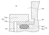
- FIG. 3 is a diagram schematically showing a collar and a bumper according to another embodiment.
- the communication passage 80 may be formed in the collar chamber 72 instead of being formed in the main body 70a or the upper end 70b of the collar 70.
- the communication passage 80 may be formed in the lower bumper 76, for example.
- the communication passage 80 may be, for example, a groove formed on the upper surface of the lower retainer 76b opposite to the lower cushioning material 76a.
- the communication path 80 formed in the color chamber 72 shown in FIG. 3 is applicable to the cryogenic refrigerator 10 shown in FIGS. 1 and 2 or another color bumper type gas driven cryogenic refrigerator.
- the communication path 80 can guarantee the communication between the upper section 72a and the lower section 72b when the displacer 20 is at the bottom dead center. Since the differential pressure that can occur between the upper section 72a and the lower section 72b is reduced or eliminated through the communication passage 80, the displacer 20 can be easily moved from the bottom dead center to the top dead center.
- the communication path 80 may be a flow path formed in the cold head housing 18.
- the communication passage 80 may extend from the upper section 72a to the lower section 72b via the sleeve 73 and the cylinder flange 26a. Even in this case, the communication path 80 can guarantee the communication between the upper section 72a and the lower section 72b when the displacer 20 is at the bottom dead center.
- the collar upper end 70b is provided radially outward with respect to the displacer 20, but such a specific shape is not essential.
- the collar upper end 70b may extend radially inward from the main body 70a and may be present inside the outer diameter of the displacer 20.
- the collar chamber 72 is not formed on the sleeve 73 side as described above, but is formed on the piston cylinder 28 side.
- the upper bumper 74 is mounted on the upper surface of the color chamber 72 and is disposed in the upper section 72a
- the lower bumper 76 is mounted on the lower surface of the color chamber 72 and is disposed in the lower section 72b.
- the upper bumper 74 and the lower bumper 76 may be attached to the collar 70.
- the upper bumper 74 may be mounted on the upper surface of the upper collar 70b and disposed in the upper compartment 72a
- the lower bumper 76 may be mounted on the lower surface of the upper collar 70b and disposed in the lower compartment 72b. Even in this case, interference (for example, collision) between the displacer 20 and the displacer cylinder 26 due to the contact between the color chamber 72 and the bumpers (74, 76) can be prevented, and vibration and noise can be reduced.
- the GM refrigerator is described as an example, but the design of the color bumper system having the communication passage 80 described above can be applied to other gas-driven cryogenic refrigerators.
- the terms "displacer” and “drive piston” in the above description may mean “first piston” and “second piston”, respectively.
- the present invention can be used in the field of cryogenic refrigerators.
- cryogenic refrigerator ⁇ 20 ⁇ displacer, ⁇ 70 ⁇ color, ⁇ 72 ⁇ color room, ⁇ 72a ⁇ upper compartment, ⁇ 72b ⁇ lower compartment, ⁇ 76 ⁇ lower bumper, ⁇ 80 ⁇ communicating passage.
Landscapes
- Engineering & Computer Science (AREA)
- Physics & Mathematics (AREA)
- Mechanical Engineering (AREA)
- Thermal Sciences (AREA)
- General Engineering & Computer Science (AREA)
- Compressors, Vaccum Pumps And Other Relevant Systems (AREA)
- Compressor (AREA)
Abstract
極低温冷凍機10は、ディスプレーサシリンダ26と、ディスプレーサシリンダ26内に配置され、ガス圧により往復動が駆動されるディスプレーサ20と、ディスプレーサ20とともに往復動するようにディスプレーサ20に剛に連結されたカラー70と、カラー70によって上部区画72aと下部区画72bとに分けられたカラー室72と、ディスプレーサ20が下死点にあるときディスプレーサ20とディスプレーサシリンダ26との干渉を緩和するように下部区画72bに設けられた下部バンパー76と、ディスプレーサ20が下死点にあるとき上部区画72aと下部区画72bとの連通を保証するようにカラー70またはカラー室72に形成された連通路80と、を備える。
Description
本発明は、極低温冷凍機に関する。
極低温冷凍機の代表例の1つであるGM(ギフォード・マクマホン、Gifford-McMahon)冷凍機は、ディスプレーサの駆動源によってモータ駆動型とガス駆動型の2種類に大きく分けられる。モータ駆動型においては、ディスプレーサがモータに機械的に連結され、モータによって駆動される。ガス駆動型においては、ディスプレーサがガス圧によって駆動される。
本発明者らは、ガス駆動型の極低温冷凍機について鋭意研究を重ねた結果、以下の課題を認識するに至った。典型的なガス駆動型の極低温冷凍機では、ガス圧によってディスプレーサがシリンダ端部に干渉(例えば衝突)するまで移動する。干渉は振動および騒音を生じさせうる。ディスプレーサとシリンダ端部との干渉を防止し、振動および騒音を低減するために、「カラーバンパー(collar bumper)」と称される設計が採用されうる。しかしながら、カラーバンパー方式のガス駆動型極低温冷凍機では、ディスプレーサが下死点に到達するとき、カラーの一方側に低圧の密閉領域が形成され、カラーの他方側の高圧領域との差圧によって上死点に向かうディスプレーサの移動が妨げられうる。
本発明のある態様の例示的な目的のひとつは、カラーバンパー方式のガス駆動型極低温冷凍機においてディスプレーサの下死点から上死点に向かう移動を容易にすることにある。
本発明のある態様によると、極低温冷凍機は、シリンダと、シリンダ内に配置され、ガス圧により往復動が駆動されるディスプレーサと、ディスプレーサとともに往復動するようにディスプレーサに剛に連結されたカラーと、カラーによって上部区画と下部区画とに分けられたカラー室と、ディスプレーサが下死点にあるときディスプレーサとシリンダとの干渉を緩和するように下部区画に設けられた下部バンパーと、ディスプレーサが下死点にあるとき上部区画と下部区画との連通を保証するようにカラーまたはカラー室に形成された連通路と、を備える。
なお、以上の構成要素の任意の組み合わせや本発明の構成要素や表現を、方法、装置、システムなどの間で相互に置換したものもまた、本発明の態様として有効である。
本発明によれば、カラーバンパー方式のガス駆動型極低温冷凍機においてディスプレーサの下死点から上死点に向かう移動を容易にすることができる。
以下、図面を参照しながら、本発明を実施するための形態について詳細に説明する。説明および図面において同一または同等の構成要素、部材、処理には同一の符号を付し、重複する説明は適宜省略する。図示される各部の縮尺や形状は、説明を容易にするために便宜的に設定されており、特に言及がない限り限定的に解釈されるものではない。実施の形態は例示であり、本発明の範囲を何ら限定するものではない。実施の形態に記述されるすべての特徴やその組み合わせは、必ずしも発明の本質的なものであるとは限らない。
図1および図2は、実施の形態に係る極低温冷凍機10を示す概略図である。極低温冷凍機10は、例えば、ガス駆動型のGM冷凍機である。
極低温冷凍機10は、作動ガス(例えばヘリウムガス)を圧縮する圧縮機12と、作動ガスを断熱膨張により冷却するコールドヘッド14と、を備える。圧縮機12は、圧縮機吐出口12a及び圧縮機吸入口12bを有する。圧縮機吐出口12a及び圧縮機吸入口12bはそれぞれ、極低温冷凍機10の高圧源及び低圧源として機能する。コールドヘッド14は膨張機とも呼ばれる。
詳しくは後述するように、圧縮機12は、圧縮機吐出口12aからコールドヘッド14に高圧(PH)の作動ガスを供給する。コールドヘッド14には作動ガスを予冷する蓄冷器15が備えられている。予冷された作動ガスは、コールドヘッド14内での膨張によって更に冷却される。作動ガスは蓄冷器15を通じて圧縮機吸入口12bに回収される。作動ガスは蓄冷器15を通るとき蓄冷器15を冷却する。圧縮機12は、回収した低圧(PL)の作動ガスを圧縮し、再びコールドヘッド14に供給する。
図示されるコールドヘッド14は単段式である。ただし、コールドヘッド14は、多段式であってもよい。
コールドヘッド14は、ガス圧で駆動されるフリーピストンとしての軸方向可動体16と、気密に構成され軸方向可動体16を収容するコールドヘッドハウジング18と、を備える。コールドヘッドハウジング18は、軸方向可動体16を軸方向に往復動可能に支持するとともに、作動ガスの圧力容器として構成されている。モータ駆動型のGM冷凍機とは異なり、コールドヘッド14は、軸方向可動体16を駆動するモータおよび連結機構(例えばスコッチヨーク機構)を有しない。
軸方向可動体16は、軸方向(図1において上下方向、矢印Cで示す)に往復動可能なディスプレーサ20と、ディスプレーサ20を軸方向に駆動するようにディスプレーサ20に同軸に連結された駆動ピストン22と、を備える。駆動ピストン22は、ディスプレーサ20が駆動ピストン22と一体に軸方向に往復動するようにディスプレーサ20に剛に連結されている。駆動ピストン22は、ディスプレーサ20に比べて小さい寸法を有する。駆動ピストン22の軸方向長さはディスプレーサ20のそれより短く、駆動ピストン22の径もディスプレーサ20のそれより小さい。
コールドヘッドハウジング18は、ディスプレーサ20を収容するディスプレーサシリンダ26と、駆動ピストン22を収容するピストンシリンダ28と、を備える。ピストンシリンダ28は、ディスプレーサシリンダ26と同軸にかつ軸方向に隣接して配設されている。詳細は後述するが、ガス駆動型であるコールドヘッド14の駆動部は、駆動ピストン22とピストンシリンダ28を含んで構成されている。ピストンシリンダ28の容積はディスプレーサシリンダ26のそれより小さい。ピストンシリンダ28の軸方向長さはディスプレーサシリンダ26のそれより短く、ピストンシリンダ28の径もディスプレーサシリンダ26のそれより小さい。
ディスプレーサ20の軸方向往復動は、ディスプレーサシリンダ26によって案内される。通例、ディスプレーサ20およびディスプレーサシリンダ26はそれぞれ軸方向に延在する円筒状の部材であり、ディスプレーサシリンダ26の内径はディスプレーサ20の外径に一致するか又はわずかに大きい。同様に、駆動ピストン22の軸方向往復動は、ピストンシリンダ28によって案内される。通例、駆動ピストン22およびピストンシリンダ28はそれぞれ軸方向に延在する円筒状の部材であり、ピストンシリンダ28の内径は駆動ピストン22の外径に一致するか又はわずかに大きい。
ディスプレーサ20と駆動ピストン22は剛に連結されているので、駆動ピストン22の軸方向ストロークはディスプレーサ20の軸方向ストロークと等しく、両者はストローク全体にわたって一体に移動する。ディスプレーサ20に対する駆動ピストン22の位置は軸方向可動体16の軸方向往復動の間、不変である。
第1シール部32が、駆動ピストン22とピストンシリンダ28の間に設けられている。第1シール部32は、駆動ピストン22またはピストンシリンダ28のいずれか一方に装着され、駆動ピストン22またはピストンシリンダ28の他方と摺動する。第1シール部32は例えば、スリッパーシールまたはOリングなどのシール部材で構成される。第1シール部32によって、ピストンシリンダ28は、ディスプレーサシリンダ26に対し気密に構成されている。第1シール部32が設けられているので、ピストンシリンダ28とディスプレーサシリンダ26との直接のガス流通は生じない。ピストンシリンダ28の内圧とディスプレーサシリンダ26の内圧は異なる大きさをとることができる。
ディスプレーサシリンダ26は、ディスプレーサ20によって膨張室34と室温室36に仕切られている。ディスプレーサ20は、軸方向一端にてディスプレーサシリンダ26との間に膨張室34を形成し、軸方向他端にてディスプレーサシリンダ26との間に室温室36を形成する。室温室36は圧縮室と呼ぶこともできる。また、コールドヘッド14には、膨張室34を外包するようディスプレーサシリンダ26に固着された冷却ステージ38が設けられている。
蓄冷器15はディスプレーサ20に内蔵されている。ディスプレーサ20はその上蓋部に、蓄冷器15を室温室36に連通する入口流路40を有する。また、ディスプレーサ20はその筒部に、蓄冷器15を膨張室34に連通する出口流路42を有する。あるいは、出口流路42は、ディスプレーサ20の下蓋部に設けられていてもよい。加えて、蓄冷器15は、上蓋部に内接する入口リテーナ41と、下蓋部に内接する出口リテーナ43と、を備える。蓄冷材は、たとえば銅製の金網でもよい。リテーナは蓄冷材よりも粗い金網でもよい。
第2シール部44が、ディスプレーサ20とディスプレーサシリンダ26の間に設けられている。第2シール部44は、例えばスリッパーシールであり、ディスプレーサ20の筒部または上蓋部に装着されている。ディスプレーサ20とディスプレーサシリンダ26とのクリアランスが第2シール部44によって封じられているので、室温室36と膨張室34との直接のガス流通(つまり蓄冷器15を迂回するガス流れ)はない。
作動ガスは、室温室36から入口流路40を通じて蓄冷器15に流入する。より正確には、作動ガスは、入口流路40から入口リテーナ41を通って蓄冷器15に流入する。作動ガスは、蓄冷器15から出口リテーナ43および出口流路42を経由して膨張室34に流入する。作動ガスが膨張室34から室温室36に戻るときは逆の経路を通る。つまり、作動ガスは、膨張室34から、出口流路42、蓄冷器15、および入口流路40を通って室温室36に戻る。蓄冷器15を迂回してクリアランスを流れようとする作動ガスは第2シール部44によって遮断される。
コールドヘッド14は、使用される現場で図示の向きに設置される。すなわち、ディスプレーサシリンダ26が鉛直方向下方に、ピストンシリンダ28が鉛直方向上方に、それぞれ配置されるようにして、コールドヘッド14は縦向きに設置される。このように、冷却ステージ38を鉛直方向下方に向ける姿勢で設置されるとき極低温冷凍機10は冷凍能力が最も高くなる。ただし、極低温冷凍機10の配置はこれに限定されない。逆に、コールドヘッド14は冷却ステージ38を鉛直方向上方に向ける姿勢で設置されてもよい。あるいは、コールドヘッド14は、横向きまたはその他の向きに設置されてもよい。コールドヘッド14はどのような姿勢で設置されたとしても冷却運転可能である。
ディスプレーサ20の往復動ストロークの膨張室34側の末端をディスプレーサ20の下死点と称し、ディスプレーサ20の往復動ストロークの室温室36側の末端をディスプレーサ20の上死点と称する。上死点に向かうディスプレーサ20の移動を上動と称し、下死点に向かうディスプレーサ20の移動を下動と称してもよい。ただし、こうした用語は、コールドヘッド14の姿勢を限定するものではない。
ディスプレーサ20が軸方向に動くとき、膨張室34および室温室36は相補的に容積を増減させる。すなわち、ディスプレーサ20が下動するとき、膨張室34は狭くなり室温室36は広くなる。逆も同様である。したがって、ディスプレーサ20が下死点に位置するとき膨張室34の容積は最小となる(室温室36の容積は最大となる)。ディスプレーサ20が上死点に位置するとき膨張室34の容積は最大となる(室温室36の容積は最小となる)。
さらに、極低温冷凍機10は、圧縮機12をコールドヘッド14に接続する作動ガス回路52を備える。作動ガス回路52は、ピストンシリンダ28とディスプレーサシリンダ26(すなわち膨張室34及び/または室温室36)との間に圧力差を生成するよう構成されている。この圧力差によって軸方向可動体16が軸方向に動く。ピストンシリンダ28に対しディスプレーサシリンダ26の圧力が低ければ、駆動ピストン22が下動し、それに伴ってディスプレーサ20も下動する。逆に、ピストンシリンダ28に対しディスプレーサシリンダ26の圧力が高ければ、駆動ピストン22が上動し、それに伴ってディスプレーサ20も上動する。
作動ガス回路52は、バルブ部54を備える。バルブ部54は、コールドヘッドハウジング18と一体となるようにピストンシリンダ28に隣接して配設され、圧縮機12と配管で接続されていてもよい。バルブ部54は、コールドヘッドハウジング18の外に配設され、圧縮機12およびコールドヘッド14それぞれと配管で接続されていてもよい。
バルブ部54は、膨張室圧力切替バルブ(以下、主圧力切替バルブともいう)60と駆動室圧力切替バルブ(以下、副圧力切替バルブともいう)62を備える。主圧力切替バルブ60は、主吸気開閉バルブV1と主排気開閉バルブV2とを有する。副圧力切替バルブ62は、副吸気開閉バルブV3と副排気開閉バルブV4とを有する。
作動ガス回路52は、圧縮機12をバルブ部54に接続する高圧ライン13aおよび低圧ライン13bを備える。高圧ライン13aは、圧縮機吐出口12aから延び、途中で分岐し、主吸気開閉バルブV1と副吸気開閉バルブV3に接続されている。低圧ライン13bは、圧縮機吸入口12bから延び、途中で分岐し、主排気開閉バルブV2と副排気開閉バルブV4に接続されている。
また、作動ガス回路52は、コールドヘッド14をバルブ部54に接続する主連通路64および副連通路66を備える。主連通路64は、ディスプレーサシリンダ26を主圧力切替バルブ60に接続する。主連通路64は、室温室36から延び、途中で分岐して、主吸気開閉バルブV1と主排気開閉バルブV2に接続されている。副連通路66は、ピストンシリンダ28を副圧力切替バルブ62に接続する。副連通路66は、ピストンシリンダ28から延び、途中で分岐して、副吸気開閉バルブV3と副排気開閉バルブV4に接続されている。
主圧力切替バルブ60は、圧縮機吐出口12aまたは圧縮機吸入口12bをディスプレーサシリンダ26の室温室36に選択的に連通するよう構成されている。主圧力切替バルブ60においては、主吸気開閉バルブV1および主排気開閉バルブV2がそれぞれ排他的に開放される。すなわち、主吸気開閉バルブV1および主排気開閉バルブV2が同時に開くことは禁止されている。なお主吸気開閉バルブV1および主排気開閉バルブV2が一時的にともに閉じられてもよい。
主吸気開閉バルブV1が開いているとき主排気開閉バルブV2は閉じられる。圧縮機吐出口12aから高圧ライン13aおよび主連通路64を通じてディスプレーサシリンダ26に作動ガスが流れる。上述のように作動ガスは室温室36から蓄冷器15を通じて膨張室34に流れる。こうして、高圧PHの作動ガスが圧縮機12から膨張室34に供給され、膨張室34は昇圧される。逆に主吸気開閉バルブV1が閉じているときは、圧縮機12から膨張室34への作動ガスの供給は停止される。
一方、主排気開閉バルブV2が開いているとき主吸気開閉バルブV1は閉じられる。まず高圧PHの作動ガスが膨張室34で膨張し減圧される。膨張室34から蓄冷器15を通じて室温室36に作動ガスが流れる。ディスプレーサシリンダ26から主連通路64および低圧ライン13bを通じて圧縮機吸入口12bに作動ガスが流れる。こうして、低圧PLの作動ガスがコールドヘッド14から圧縮機12に回収される。主排気開閉バルブV2が閉じているときは、膨張室34から圧縮機12への作動ガスの回収は停止される。
副圧力切替バルブ62は、圧縮機吐出口12aまたは圧縮機吸入口12bをピストンシリンダ28に選択的に連通するよう構成されている。副圧力切替バルブ62は、副吸気開閉バルブV3および副排気開閉バルブV4がそれぞれ排他的に開放されるよう構成されている。すなわち、副吸気開閉バルブV3および副排気開閉バルブV4が同時に開くことは禁止されている。なお副吸気開閉バルブV3および副排気開閉バルブV4が一時的にともに閉じられてもよい。
副吸気開閉バルブV3が開いているとき副排気開閉バルブV4は閉じられる。圧縮機吐出口12aから高圧ライン13aおよび副連通路66を通じてピストンシリンダ28に作動ガスが流れる。こうして、高圧PHの作動ガスが圧縮機12からピストンシリンダ28に供給され、ピストンシリンダ28は昇圧される。副吸気開閉バルブV3が閉じているときは、圧縮機12からピストンシリンダ28への作動ガスの供給は停止される。
一方、副排気開閉バルブV4が開いているとき副吸気開閉バルブV3は閉じられる。ピストンシリンダ28から副連通路66および低圧ライン13bを通じて圧縮機吸入口12bに作動ガスが回収され、ピストンシリンダ28は低圧PLに降圧される。副排気開閉バルブV4が閉じているときは、ピストンシリンダ28から圧縮機12への作動ガスの回収は停止される。
このようにして、主圧力切替バルブ60は、高圧PHと低圧PLの周期的な圧力変動を膨張室34に生成する。また、副圧力切替バルブ62は、ピストンシリンダ28に高圧PHと低圧PLの周期的な圧力変動を生成する。
副圧力切替バルブ62は、駆動ピストン22がディスプレーサ20の軸方向往復動を駆動するようにピストンシリンダ28の圧力を制御するように構成されている。典型的には、ピストンシリンダ28での圧力変動は、膨張室34での圧力変動と同じ周期でほぼ逆の位相で生成される。膨張室34が高圧PHのときピストンシリンダ28は低圧PLとなり、駆動ピストン22はディスプレーサ20を上動させることができる。膨張室34が低圧PLのときピストンシリンダ28は高圧PHとなり、駆動ピストン22はディスプレーサ20を下動させることができる。
バルブ部54は、ロータリーバルブの形式をとってもよい。この場合、一群のバルブ(V1~V4)がバルブ部54に組み込まれており、同期して駆動される。バルブ部54は、バルブ本体(またはバルブステータ)に対するバルブディスク(またはバルブロータ)の回転摺動によってバルブ(V1~V4)が適正に切り替わるよう構成されている。一群のバルブ(V1~V4)は、極低温冷凍機10の運転中に同一周期で切り替えられ、それにより4つの開閉バルブ(V1~V4)は周期的に開閉状態を変化させる。4つの開閉バルブ(V1~V4)はそれぞれ異なる位相で開閉される。
極低温冷凍機10は、バルブ部54を回転させるようバルブ部54に連結された回転駆動源56を備えてもよい。回転駆動源56はバルブ部54と機械的に連結される。回転駆動源56は例えばモータである。ただし、回転駆動源56は、軸方向可動体16には機械的に接続されていない。また、極低温冷凍機10は、バルブ部54を制御する制御部58を備えてもよい。制御部58は、回転駆動源56を制御してもよい。
ある実施形態においては、一群のバルブ(V1~V4)は、複数の個別に制御可能なバルブの形式をとってもよい。各バルブ(V1~V4)は、電磁開閉弁であってもよい。この場合、回転駆動源56が設けられるのではなく、各バルブ(V1~V4)は、制御部58に電気的に接続される。制御部58は、各バルブ(V1~V4)の開閉を制御してもよい。
図1には、ディスプレーサ20が下死点に位置する状態が示され、図2には、ディスプレーサ20が上死点に位置する状態が示されている。
極低温冷凍機10はカラーバンパー方式であるため、コールドヘッド14は、カラー70と、カラー70によって上部区画72aと下部区画72bとに分けられたカラー室72とを備える。カラー70は、ディスプレーサ20とともに往復動するようにディスプレーサ20に剛に連結されており、軸方向可動体16の一部を構成する。後述するように、カラー室72におけるカラー70の往復動ストロークがディスプレーサ20の往復動ストロークを定めている。
ディスプレーサシリンダ26は、シリンダ上部開口を定めるシリンダフランジ26aを備える。シリンダフランジ26aは、ディスプレーサシリンダ26の軸方向上端から径方向外側に延出している。コールドヘッドハウジング18は、天板30とスリーブ73とを備える。ピストンシリンダ28およびスリーブ73は天板30に固定され、バルブ部54が天板30上に搭載されている。シリンダフランジ26aはスリーブ73を介して天板30に接続されている。スリーブ73は、ピストンシリンダ28を囲むようにピストンシリンダ28の外側に配置されている。
カラー70は、筒状の本体70aと、カラー上端70bとを備える。本体70aは、ディスプレーサ20とほぼ同一の外径を有し、ディスプレーサ20の室温室36側から上方に延びている。本体70aの内径は、ピストンシリンダ28の外径より大きい。カラー上端70bは、ディスプレーサ20の外径よりも外側に存在する。カラー上端70bによって、カラー室72は、上部区画72aと下部区画72bとに分けられている。カラー室72は、室温室36に連通している。ディスプレーサ20がディスプレーサシリンダ26内を往復するとき、カラー70は、ディスプレーサシリンダ26およびピストンシリンダ28と摩擦することなくカラー室72を往復する。カラー70は、スリーブ73の内周面と摩擦することもない。
また、コールドヘッド14は、ディスプレーサ20が上死点にあるときディスプレーサ20とディスプレーサシリンダ26との干渉を緩和するように上部区画72aに設けられた上部バンパー74を備える。上部バンパー74は、カラー室72の上面に設置され、上部緩衝材74aおよび上部リテーナ74bを有する。上部バンパー74は、例えば、スリーブ73に取り付けられている。上部緩衝材74aは、例えばOリングのような樹脂製の環状部材であり、カラー室72の上面と上部リテーナ74bに挟まれている。上部リテーナ74bは例えば樹脂材料で形成されている。なお、上部リテーナ74bは設けられていなくてもよい。
上部バンパー74は、ディスプレーサ20が上死点に位置するときカラー70と接触し、ディスプレーサ20とディスプレーサシリンダ26との室温室36側での衝突を防止する。カラー上端70bは、ディスプレーサ20が上動するときディスプレーサ20がピストンシリンダ28に衝突する前に、カラー室72内で上部バンパー74と係合する。このとき、カラー上端70bは上部リテーナ74bに接触し、上部緩衝材74aが圧縮され、衝撃が吸収される。
コールドヘッド14は、ディスプレーサ20が下死点にあるときディスプレーサ20とディスプレーサシリンダ26との干渉を緩和するように下部区画72bに設けられた下部バンパー76を備える。下部バンパー76は、カラー室72の下面に設置され、下部緩衝材76aおよび下部リテーナ76bを有する。下部バンパー76は、例えば、シリンダフランジ26aに取り付けられている。下部バンパー76は、スリーブ73に取り付けられていてもよい。下部緩衝材76aは、例えばOリングのような樹脂製の環状部材であり、カラー室72の下面と下部リテーナ76bに挟まれている。下部リテーナ76bは例えば樹脂材料で形成されている。なお、下部リテーナ76bは設けられていなくてもよい。
下部バンパー76は、ディスプレーサ20が下死点に位置するときカラー70と接触し、ディスプレーサ20とディスプレーサシリンダ26との膨張室34側での衝突を防止する。カラー上端70bは、ディスプレーサ20が下動するときディスプレーサ20が膨張室34側でディスプレーサシリンダ26と衝突する前に、カラー室72内で下部バンパー76と係合する。このとき、カラー上端70bは下部リテーナ76bに接触し、下部緩衝材76aが圧縮され、衝撃が吸収される。
上部区画72aは、室温室36と連通している。ピストンシリンダ28の外周面とカラー70の内周面との間に第1隙間78aが形成され、第1隙間78aを通じて室温室36と上部区画72aとの間で作動ガスが流れることができる。
下部区画72bは、上部区画72aと連通している。スリーブ73の内周面とカラー上端70bの外周面との間に第2隙間78bが形成され、第2隙間78bを通じて上部区画72aと下部区画72bとの間で作動ガスが流れることができる。ただし、ディスプレーサ20が下死点に位置するときには、カラー上端70bが下部バンパー76と接触し、第2隙間78bを通じた下部区画72bと上部区画72aの連通は遮断される。ディスプレーサ20が上死点に位置するときには、カラー上端70bが上部バンパー74と接触し、第2隙間78bを通じた下部区画72bと上部区画72aの連通は遮断される。よって、ディスプレーサ20が上死点と下死点との間の中間位置にあるとき、下部区画72bは、上部区画72aを通じて室温室36に連通し、室温室36と下部区画72bとの間で作動ガスが流れることができる。また、下部区画72bは、第2シール部44によって封じられているので、膨張室34とは連通していない。
また、コールドヘッド14は、ディスプレーサ20が下死点にあるとき上部区画72aと下部区画72bとの連通を保証する連通路80を備える。連通路80は、カラー上端70bが下部バンパー76と接触した状態において上部区画72aが下部区画72bと連通するように、カラー70に形成されている。連通路80は、上部区画72aから下部区画72bへとカラー70(例えばカラー上端70b)を貫通するように形成され、周方向に少なくとも1つあればよい。図示されるように、カラー上端70bがカラー70の本体70aから径方向外向きに延出している場合には、連通路80は、下部バンパー76に対して径方向内側の位置においてカラー上端70bに形成される。連通路80は、カラー70の本体70aを貫通するように形成されてもよい。
第1隙間78a、第2隙間78b、および連通路80は、流路抵抗として働く。そのため、ディスプレーサ20が往復するとき、上部区画72aおよび下部区画72bはそれぞれガスばね力を発生させることができる。ディスプレーサ20が上動するとともにカラー上端70bも上動し、上部区画72aは狭くなる。このとき上部区画72aのガスは圧縮され、圧力が高まる。上部区画72aの圧力はカラー上端70bの上面に下向きに作用する。よって、上部区画72aは、カラー70およびディスプレーサ20の上動に抗するガスばね力を発生させる。同様に、ディスプレーサ20が下動するとき、下部区画72bは、カラー70およびディスプレーサ20の下動に抗するガスばね力を発生させる。上部区画72aおよび下部区画72bはそれぞれ、上部ガスばね室および下部ガスばね室と称してもよい。ガスばね力は、カラー70が上部バンパー74および下部バンパー76と接触するとき生じうる振動および騒音を低減することに役立つ。
極低温冷凍機10の動作を説明する。ディスプレーサ20が下死点またはその近傍の位置にあるとき、極低温冷凍機10の吸気工程が開始される。主吸気開閉バルブV1は開かれ、主排気開閉バルブV2は閉じる。圧縮機吐出口12aから主吸気開閉バルブV1を通じてコールドヘッド14のディスプレーサシリンダ26に作動ガスが供給され、膨張室34および室温室36は、高圧PHとなる。膨張室34への吸気と同時にピストンシリンダ28の排気が行われる。副吸気開閉バルブV3は閉じ、副排気開閉バルブV4が開かれる。ピストンシリンダ28から副排気開閉バルブV4を通じて圧縮機吸入口12bへと作動ガスが排出され、ピストンシリンダ28は低圧PLへと降圧される。
したがって、吸気工程において駆動ピストン22にはピストンシリンダ28と膨張室34との差圧(PH-PL)による駆動力が上向きに作用する。その結果、ディスプレーサ20は駆動ピストン22とともに、下死点から上死点に向けて動く。こうして、膨張室34の容積が増加されるとともに高圧ガスで満たされる。
ディスプレーサ20とともにカラー70も上動する。カラー70は、ディスプレーサ20がディスプレーサシリンダ26の高温端部(例えばピストンシリンダ28)と衝突する前に、上部バンパー74に接触する。上部緩衝材74aが圧縮され、衝撃が吸収される。カラー70が上動する間、上部区画72aは第1隙間78aを通じて室温室36に連通し、下部区画72bは第2隙間78bおよび連通路80を通じて上部区画72aに連通しているから、上部区画72aおよび下部区画72bは、室温室36と同様に高圧PHとなる。
ディスプレーサ20が上死点またはその近傍の位置にあるとき、極低温冷凍機10の排気工程が開始される。主排気開閉バルブV2が開かれ、主吸気開閉バルブV1は閉じる。高圧ガスは膨張室34で膨張し冷却される。膨張したガスは、蓄冷器15を冷却しながら室温室36を経て圧縮機吸入口12bに回収される。膨張室34および室温室36は、低圧PLとなる。膨張室34からの排気と同時にピストンシリンダ28への吸気が行われる。副排気開閉バルブV4は閉じ、副吸気開閉バルブV3が開かれる。圧縮機吐出口12aから副吸気開閉バルブV3を通じてピストンシリンダ28に作動ガスが供給され、ピストンシリンダ28は高圧PHへと昇圧される。
したがって、排気工程において駆動ピストン22にはピストンシリンダ28と膨張室34との差圧(PH-PL)による駆動力が下向きに作用する。その結果、ディスプレーサ20は駆動ピストン22とともに、上死点から下死点に向けて動く。こうして、膨張室34の容積が減少されるとともに低圧ガスは排出される。
ディスプレーサ20とともにカラー70も下動する。カラー70は、ディスプレーサ20がディスプレーサシリンダ26の低温端部と衝突する前に、下部バンパー76に接触する。下部緩衝材76aが圧縮され、衝撃が吸収される。カラー70が下動する間、上部区画72aは第1隙間78aを通じて室温室36に連通し、下部区画72bは第2隙間78bおよび連通路80を通じて上部区画72aに連通しているから、上部区画72aおよび下部区画72bは、室温室36と同様に低圧PLとなる。
極低温冷凍機10はこのような冷凍サイクル(すなわちGMサイクル)を繰り返すことで、冷却ステージ38を冷却する。それにより、極低温冷凍機10は、冷却ステージ38に熱的に結合された被冷却物(図示せず)を冷却することができる。
極低温冷凍機10は、カラーバンパー方式であるため、カラー70とバンパー(74、76)との接触によりディスプレーサ20とディスプレーサシリンダ26との干渉(例えば衝突)を防止し、振動および騒音を低減することができる。
ところで、典型的なカラーバンパー方式のガス駆動型極低温冷凍機は、上述の実施の形態と異なり、連通路80を有しない。この場合、カラー70が下死点に位置するとき、下部区画72bには低圧PLの作動ガスが密閉されうる。この状態において吸気工程の開始時に上部区画72aが高圧PHに昇圧されると、カラー上端70bが差圧(PH-PL)によって下部バンパー76に押し付けられうる。この差圧力は、ディスプレーサ20の上動を妨げうる。
しかしながら、実施の形態に係る極低温冷凍機10は、ディスプレーサ20が下死点にあるとき上部区画72aと下部区画72bとの連通を保証するようにカラー70に形成された連通路80を備える。そのため、カラー70が下死点に位置しカラー上端70bが下部バンパー76に接触していても、下部区画72bが連通路80を通じて上部区画72aに連通している。下部区画72bは密閉されない。上部区画72aと下部区画72bとの間に生じうる差圧は連通路80を通じて低減または解消されるので、ディスプレーサ20の上動は妨げられない。したがって、ディスプレーサ20は下死点から上死点に向けて移動することができる。
連通路80は、カラー70に形成されている。このようにすれば、製造上、連通路80を形成することが容易である。
図3は、他の実施の形態に係るカラーおよびバンパーを概略的に示す図である。図示されるように、連通路80は、カラー70の本体70aまたはカラー上端70bに形成されるのではなく、カラー室72に形成されてもよい。連通路80は、例えば、下部バンパー76に形成されてもよい。連通路80は、例えば、下部緩衝材76aとは反対側となる下部リテーナ76bの上面に形成された溝であってもよい。図3に示されるカラー室72に形成された連通路80は、図1および図2に示される極低温冷凍機10またはその他のカラーバンパー方式のガス駆動型極低温冷凍機に適用可能である。
このようにしても、連通路80は、ディスプレーサ20が下死点にあるとき上部区画72aと下部区画72bとの連通を保証することができる。上部区画72aと下部区画72bとの間に生じうる差圧は連通路80を通じて低減または解消されるので、ディスプレーサ20の下死点から上死点に向かう移動を容易にすることができる。
連通路80がカラー室72に形成される他の例においては、連通路80は、コールドヘッドハウジング18に形成された流路であってもよい。例えば、連通路80は、上部区画72aからスリーブ73およびシリンダフランジ26aを経由して下部区画72bへと延びていてもよい。このようにしても、連通路80は、ディスプレーサ20が下死点にあるとき上部区画72aと下部区画72bとの連通を保証することができる。
以上、本発明を実施例にもとづいて説明した。本発明は上記実施形態に限定されず、種々の設計変更が可能であり、様々な変形例が可能であること、またそうした変形例も本発明の範囲にあることは、当業者に理解されるところである。ある実施の形態に関連して説明した種々の特徴は、他の実施の形態にも適用可能である。組合せによって生じる新たな実施の形態は、組み合わされる実施の形態それぞれの効果をあわせもつ。
上述の実施の形態では、カラー上端70bは、ディスプレーサ20に対して径方向に外側に設けられているが、こうした具体的形状であることは必須ではない。例えば、カラー上端70bは、本体70aから径方向に内向きに延出し、ディスプレーサ20の外径よりも内側に存在してもよい。この場合、カラー室72は、上述のようにスリーブ73側に形成されるのではなく、ピストンシリンダ28側に形成される。
上述の実施の形態では、上部バンパー74は、カラー室72の上面に取り付けられ、上部区画72aに配置され、下部バンパー76は、カラー室72の下面に取り付けられ、下部区画72bに配置されている。しかし、上部バンパー74および下部バンパー76がカラー70に取り付けられてもよい。例えば、上部バンパー74がカラー上端70bの上面に取り付けられて上部区画72aに配置され、下部バンパー76がカラー上端70bの下面に取り付けられて下部区画72bに配置されてもよい。このようにしても、カラー室72とバンパー(74、76)との接触によりディスプレーサ20とディスプレーサシリンダ26との干渉(例えば衝突)を防止し、振動および騒音を低減することができる。
上述の実施の形態は、GM冷凍機を例として説明したが、上述の連通路80を有するカラーバンパー方式の設計は、ガス駆動型の他の極低温冷凍機にも適用されうる。その場合、上述の説明における「ディスプレーサ」および「駆動ピストン」との用語はそれぞれ、「第1ピストン」および「第2ピストン」を意味しうる。
本発明は、極低温冷凍機の分野における利用が可能である。
10 極低温冷凍機、 20 ディスプレーサ、 70 カラー、 72 カラー室、 72a 上部区画、 72b 下部区画、 76 下部バンパー、 80 連通路。
Claims (10)
- シリンダと、
前記シリンダ内に配置され、ガス圧により往復動が駆動されるディスプレーサと、
前記ディスプレーサとともに往復動するように前記ディスプレーサに剛に連結されたカラーと、
前記カラーによって上部区画と下部区画とに分けられたカラー室と、
前記ディスプレーサが下死点にあるとき前記ディスプレーサと前記シリンダとの干渉を緩和するように前記下部区画に設けられた下部バンパーと、
前記ディスプレーサが下死点にあるとき前記上部区画と前記下部区画との連通を保証するように前記カラーまたは前記カラー室に形成された連通路と、を備えることを特徴とする極低温冷凍機。 - 前記連通路は、前記カラーに形成されていることを特徴とする請求項1に記載の極低温冷凍機。
- 前記カラーは、前記ディスプレーサの軸方向に前記ディスプレーサから上方に延在する筒状の本体と、前記本体から径方向に延出するカラー上端と、を備え、
前記連通路は、前記ディスプレーサの軸方向に前記カラー上端を貫通していることを特徴とする請求項2に記載の極低温冷凍機。 - 前記連通路は、前記下部バンパーに形成されていることを特徴とする請求項1に記載の極低温冷凍機。
- 前記下部バンパーは、前記カラー室の下面に設置された下部緩衝材および下部リテーナを備え、
前記連通路は、前記下部緩衝材とは反対側となる前記下部リテーナの上面に形成された溝を含むことを特徴とする請求項4に記載の極低温冷凍機。 - 前記シリンダを含むコールドヘッドハウジングと、
前記ディスプレーサが上死点にあるとき前記ディスプレーサと前記コールドヘッドハウジングとの干渉を緩和するように前記上部区画に設けられた上部バンパーと、をさらに備えることを特徴とする請求項1から5のいずれかに記載の極低温冷凍機。 - 前記カラー室の前記上部区画は、上部ガスばね室として働き、前記カラー室の前記下部区画は、下部ガスばね室として働くことを特徴とする請求項1から6のいずれかに記載の極低温冷凍機。
- 前記ディスプレーサは、軸方向一端にて前記シリンダとの間に膨張室を形成し、軸方向他端にて前記シリンダとの間に室温室を形成し、
第1隙間が、前記カラーの内周面に径方向に内側に隣接して形成され、第2隙間が、前記カラーの外周面に径方向に外側に隣接して形成され、
前記カラー室の前記上部区画は、前記第1隙間を通じて前記室温室と連通し、
前記カラー室の前記下部区画は、前記第1隙間、前記上部区画、前記第2隙間を通じて前記室温室と連通し、
前記ディスプレーサが下死点にあるとき前記第2隙間を通じた前記下部区画と前記上部区画の連通が遮断されることを特徴とする請求項1から7のいずれかに記載の極低温冷凍機。 - 前記ディスプレーサを往復動させる前記ガス圧を制御するバルブ部と、
前記バルブ部を駆動する駆動源と、をさらに備え、
前記ディスプレーサおよび前記カラーは、前記駆動源と機械的に連結されていないことを特徴とする請求項1から8のいずれかに記載の極低温冷凍機。 - 前記極低温冷凍機は、ガス駆動型GM冷凍機であることを特徴とする請求項1から9のいずれかに記載の極低温冷凍機。
Priority Applications (2)
| Application Number | Priority Date | Filing Date | Title |
|---|---|---|---|
| CN201980057658.7A CN112639378B (zh) | 2018-09-07 | 2019-08-06 | 超低温制冷机 |
| US17/185,996 US11774147B2 (en) | 2018-09-07 | 2021-02-26 | Cryocooler |
Applications Claiming Priority (2)
| Application Number | Priority Date | Filing Date | Title |
|---|---|---|---|
| JP2018-167725 | 2018-09-07 | ||
| JP2018167725A JP7195824B2 (ja) | 2018-09-07 | 2018-09-07 | 極低温冷凍機 |
Related Child Applications (1)
| Application Number | Title | Priority Date | Filing Date |
|---|---|---|---|
| US17/185,996 Continuation US11774147B2 (en) | 2018-09-07 | 2021-02-26 | Cryocooler |
Publications (1)
| Publication Number | Publication Date |
|---|---|
| WO2020049936A1 true WO2020049936A1 (ja) | 2020-03-12 |
Family
ID=69722417
Family Applications (1)
| Application Number | Title | Priority Date | Filing Date |
|---|---|---|---|
| PCT/JP2019/031007 WO2020049936A1 (ja) | 2018-09-07 | 2019-08-06 | 極低温冷凍機 |
Country Status (4)
| Country | Link |
|---|---|
| US (1) | US11774147B2 (ja) |
| JP (1) | JP7195824B2 (ja) |
| CN (1) | CN112639378B (ja) |
| WO (1) | WO2020049936A1 (ja) |
Citations (5)
| Publication number | Priority date | Publication date | Assignee | Title |
|---|---|---|---|---|
| JPH0244662U (ja) * | 1988-09-20 | 1990-03-27 | ||
| JPH08303889A (ja) * | 1995-05-09 | 1996-11-22 | Daikin Ind Ltd | 極低温冷凍機 |
| JP2003523496A (ja) * | 2000-02-15 | 2003-08-05 | インターマグネティクス ゼネラル コーポレイション | 空気圧駆動gm型ディスプレーサを有する低振動冷却装置 |
| JP2018036042A (ja) * | 2016-07-25 | 2018-03-08 | スミトモ (エスエイチアイ) クライオジェニックス オブ アメリカ インコーポレイテッドSumitomo(SHI)Cryogenics of America,Inc. | 騒音および振動を低減するためのカラーバンパを備えた極低温膨張機 |
| WO2018101271A1 (ja) * | 2016-11-30 | 2018-06-07 | 住友重機械工業株式会社 | Gm冷凍機 |
Family Cites Families (10)
| Publication number | Priority date | Publication date | Assignee | Title |
|---|---|---|---|---|
| DE3044427C2 (de) * | 1980-11-26 | 1986-10-30 | Leybold-Heraeus GmbH, 5000 Köln | Verdränger für Tieftemperatur-Kältemaschinen |
| US4526008A (en) * | 1983-03-21 | 1985-07-02 | Texas Instruments Incorporated | Pneumatically controlled split cycle cooler |
| JPH02197765A (ja) | 1989-01-25 | 1990-08-06 | Daikin Ind Ltd | 極低温冷凍機の衝撃吸収装置 |
| JPH08313094A (ja) * | 1995-05-16 | 1996-11-29 | Toshiba Corp | 蓄冷式冷凍機 |
| JP2007205608A (ja) * | 2006-01-31 | 2007-08-16 | Sumitomo Heavy Ind Ltd | 蓄冷器式冷凍機 |
| JP6202483B2 (ja) * | 2012-06-12 | 2017-09-27 | 住友重機械工業株式会社 | 極低温冷凍機 |
| JP6109057B2 (ja) * | 2013-12-16 | 2017-04-05 | 住友重機械工業株式会社 | 蓄冷器式冷凍機 |
| JP6188619B2 (ja) * | 2014-04-02 | 2017-08-30 | 住友重機械工業株式会社 | 極低温冷凍機 |
| CN110446897B (zh) * | 2017-03-30 | 2020-11-20 | 住友重机械工业株式会社 | 超低温制冷机及磁屏蔽件 |
| CN108931067B (zh) * | 2017-05-24 | 2020-11-03 | 中南大学 | 一种蒸汽压缩制冷系统驱动的脉管式制冷装置 |
-
2018
- 2018-09-07 JP JP2018167725A patent/JP7195824B2/ja active Active
-
2019
- 2019-08-06 WO PCT/JP2019/031007 patent/WO2020049936A1/ja active Application Filing
- 2019-08-06 CN CN201980057658.7A patent/CN112639378B/zh active Active
-
2021
- 2021-02-26 US US17/185,996 patent/US11774147B2/en active Active
Patent Citations (5)
| Publication number | Priority date | Publication date | Assignee | Title |
|---|---|---|---|---|
| JPH0244662U (ja) * | 1988-09-20 | 1990-03-27 | ||
| JPH08303889A (ja) * | 1995-05-09 | 1996-11-22 | Daikin Ind Ltd | 極低温冷凍機 |
| JP2003523496A (ja) * | 2000-02-15 | 2003-08-05 | インターマグネティクス ゼネラル コーポレイション | 空気圧駆動gm型ディスプレーサを有する低振動冷却装置 |
| JP2018036042A (ja) * | 2016-07-25 | 2018-03-08 | スミトモ (エスエイチアイ) クライオジェニックス オブ アメリカ インコーポレイテッドSumitomo(SHI)Cryogenics of America,Inc. | 騒音および振動を低減するためのカラーバンパを備えた極低温膨張機 |
| WO2018101271A1 (ja) * | 2016-11-30 | 2018-06-07 | 住友重機械工業株式会社 | Gm冷凍機 |
Also Published As
| Publication number | Publication date |
|---|---|
| CN112639378B (zh) | 2022-09-09 |
| US11774147B2 (en) | 2023-10-03 |
| JP7195824B2 (ja) | 2022-12-26 |
| US20210180834A1 (en) | 2021-06-17 |
| JP2020041718A (ja) | 2020-03-19 |
| CN112639378A (zh) | 2021-04-09 |
Similar Documents
| Publication | Publication Date | Title |
|---|---|---|
| JP6966886B2 (ja) | 騒音および振動を低減するためのカラーバンパを備えた極低温膨張機 | |
| US11221079B2 (en) | Cryocooler and rotary valve unit for cryocooler | |
| US11408406B2 (en) | GM cryocooler and method of operating GM cryocooler | |
| US11384963B2 (en) | GM cryocooler | |
| WO2020049936A1 (ja) | 極低温冷凍機 | |
| US11971108B2 (en) | Rotary valve of cryocooler and cryocooler | |
| WO2018101273A1 (ja) | Gm冷凍機およびgm冷凍機の運転方法 | |
| JP6573845B2 (ja) | 極低温冷凍機 | |
| US11333407B2 (en) | GM cryocooler with buffer volume communicating with drive chamber | |
| JP6842373B2 (ja) | 極低温冷凍機 | |
| JP6998776B2 (ja) | Gm冷凍機 | |
| US11530847B2 (en) | Cryocooler and flow path switching mechanism of cryocooler | |
| JP2007205679A (ja) | 蓄冷器式冷凍機 | |
| JP6532392B2 (ja) | 極低温冷凍機 | |
| CN109196289B (zh) | Gm制冷机 | |
| JP2002115652A (ja) | リニアコンプレッサ | |
| JP2017048937A (ja) | 極低温冷凍機 | |
| CN112236628A (zh) | 脉冲管制冷机 |
Legal Events
| Date | Code | Title | Description |
|---|---|---|---|
| 121 | Ep: the epo has been informed by wipo that ep was designated in this application |
Ref document number: 19857801 Country of ref document: EP Kind code of ref document: A1 |
|
| NENP | Non-entry into the national phase |
Ref country code: DE |
|
| 122 | Ep: pct application non-entry in european phase |
Ref document number: 19857801 Country of ref document: EP Kind code of ref document: A1 |