WO2020045285A1 - 残留塩素計および残留塩素濃度測定方法 - Google Patents
残留塩素計および残留塩素濃度測定方法 Download PDFInfo
- Publication number
- WO2020045285A1 WO2020045285A1 PCT/JP2019/033076 JP2019033076W WO2020045285A1 WO 2020045285 A1 WO2020045285 A1 WO 2020045285A1 JP 2019033076 W JP2019033076 W JP 2019033076W WO 2020045285 A1 WO2020045285 A1 WO 2020045285A1
- Authority
- WO
- WIPO (PCT)
- Prior art keywords
- residual chlorine
- voltage
- electrode
- pretreatment
- working electrode
- Prior art date
- Legal status (The legal status is an assumption and is not a legal conclusion. Google has not performed a legal analysis and makes no representation as to the accuracy of the status listed.)
- Ceased
Links
Images





Classifications
-
- G—PHYSICS
- G01—MEASURING; TESTING
- G01N—INVESTIGATING OR ANALYSING MATERIALS BY DETERMINING THEIR CHEMICAL OR PHYSICAL PROPERTIES
- G01N27/00—Investigating or analysing materials by the use of electric, electrochemical, or magnetic means
- G01N27/26—Investigating or analysing materials by the use of electric, electrochemical, or magnetic means by investigating electrochemical variables; by using electrolysis or electrophoresis
- G01N27/28—Electrolytic cell components
- G01N27/30—Electrodes, e.g. test electrodes; Half-cells
- G01N27/38—Cleaning of electrodes
-
- G—PHYSICS
- G01—MEASURING; TESTING
- G01N—INVESTIGATING OR ANALYSING MATERIALS BY DETERMINING THEIR CHEMICAL OR PHYSICAL PROPERTIES
- G01N27/00—Investigating or analysing materials by the use of electric, electrochemical, or magnetic means
- G01N27/26—Investigating or analysing materials by the use of electric, electrochemical, or magnetic means by investigating electrochemical variables; by using electrolysis or electrophoresis
- G01N27/416—Systems
Definitions
- the present invention relates to a residual chlorine meter and a residual chlorine concentration measuring method for measuring the residual chlorine concentration of a test liquid such as tap water.
- a galvanic residual chlorine meter is known as a reagentless residual chlorine meter.
- a galvanic residual chlorine analyzer a platinum electrode or a gold electrode is used as a working electrode, a silver / silver chloride electrode is used as a reference electrode, and both electrodes are immersed in a test solution such as tap water to reduce the voltage between the two electrodes. Then, the residual chlorine concentration of the test solution is measured based on the measured value.
- the measurement principle of the carbani type residual chlorine meter is generally as follows. That is, when the working electrode and the reference electrode are immersed in the test solution, a current flows between the electrodes due to the oxidation-reduction reaction, and a potential difference occurs between the electrodes. The potential difference between the electrodes differs depending on the residual chlorine concentration of the test solution. Therefore, the residual chlorine concentration of the test solution can be measured based on the potential difference (voltage) between the electrodes.
- a polarographic residual chlorine meter is also known as another type of reagent-free residual chlorine meter.
- the polarographic residual chlorine meter also uses a platinum or gold electrode as a working electrode, a silver / silver chloride electrode as a counter electrode, and both electrodes, such as tap water, similarly to the galvanic residual chlorine meter. It is immersed in the test solution to measure the residual chlorine concentration of the test solution.
- the polarographic residual chlorine meter unlike the galvanic residual chlorine meter, applies a voltage between the electrodes and, in that state, measures the residual chlorine concentration of the test solution based on the current value between the electrodes. .
- the measurement principle of the polarographic residual chlorine meter is generally as follows.
- the working electrode and the counter electrode are immersed in the test solution, and a voltage is applied between the electrodes.
- the applied voltage is increased in the negative direction
- the reduction reaction proceeds, and the current flowing between the electrodes increases.
- the applied voltage is further increased in the negative direction
- a phenomenon occurs in which the current flowing between the electrodes does not change even when the applied voltage is changed.
- the applied voltage is continuously increased in the negative direction
- the current flowing between the electrodes starts to increase again.
- the current value between the electrodes determined according to the residual chlorine concentration of the test solution can be stably measured. Therefore, by applying an applied voltage having a voltage value at which the above phenomenon occurs between the electrodes and measuring the current value between the electrodes in that state, the residual chlorine concentration of the test solution can be accurately measured.
- the measurement of the residual chlorine concentration causes the oxidation-reduction reaction products and the like to adhere to the working electrode.
- the measurement accuracy of the residual chlorine concentration decreases.
- the following method is known as a method for suppressing the decrease in the measurement accuracy of the residual chlorine concentration.
- a method of wiping a redox reaction product or the like attached to a working electrode using a soft cloth or a melamine sponge before measurement is mainly known in a portable type galvanic residual chlorine meter.
- polishing beads are contained in a container.
- the working electrode is polished with polishing beads by storing and arranging the working electrode so as to face the container, and by circulating the working electrode using a motor or by pouring the test liquid into the container.
- a known method is known (see Patent Document 1 below).
- the method of wiping the redox reaction products and the like attached to the working electrode with a melamine sponge or the like has a problem that the user has to perform the work of wiping the working electrode before measurement, which is troublesome.
- the test liquid is led to a device for circularly moving the working electrode with a motor or a container containing the polishing beads. Therefore, a large-scale device such as a device for pouring a test liquid into the container is required, and there is a problem that the size and complexity of the residual chlorine meter or an increase in price are caused.
- the present invention has been made in consideration of, for example, the above-described problems, and an object of the present invention is to utilize a decrease in the measurement accuracy of the residual chlorine concentration caused by the redox reaction products and the like adhering to a working electrode. It is an object of the present invention to provide a residual chlorine meter and a residual chlorine concentration measuring method which can suppress the trouble without requiring a user and without increasing the size, complexity or cost of the residual chlorine meter.
- the residual chlorine meter of the present invention includes a first electrode serving as a working electrode and a second electrode serving as a reference electrode or a counter electrode immersed in a test solution, and A measurement unit that measures the residual chlorine concentration of the test solution based on a voltage between the second electrode and a pretreatment unit that applies a pretreatment voltage between the first electrode and the second electrode; After the application of the pretreatment voltage, the application of the pretreatment voltage is stopped, and thereafter, a control unit that controls the measurement unit and the pretreatment unit so as to measure the residual chlorine concentration of the test solution is provided.
- the residual chlorine meter of the present invention by applying the pretreatment voltage between the first electrode and the second electrode, the first or the previous measurement of the residual chlorine concentration is performed to measure the first chlorine. At least a part of the oxidation-reduction reaction product and the like attached to the electrode can be removed. Then, by measuring the residual chlorine concentration after the application of the pretreatment voltage, it is possible to suppress a decrease in the measurement accuracy of the residual chlorine concentration due to the adhesion of the oxidation-reduction reaction product and the like to the first electrode. Can be. Therefore, the work of wiping the redox reaction products and the like attached to the working electrode with a melamine sponge or the like before the measurement can be eliminated. Further, a large-scale apparatus for polishing the working electrode with the polishing beads can be omitted.
- the pretreatment section may be configured to sweep the pretreatment voltage. By sweeping the pretreatment voltage, it is possible to stabilize the measurement accuracy of the residual chlorine concentration of the test liquid as compared with the case where a DC pretreatment voltage is applied.
- the pretreatment unit may be configured to sweep the pretreatment voltage around 0 V so that the plus side amplitude and the minus side amplitude are equal to each other. With this configuration, it is possible to prevent the design of the electric circuit forming the preprocessing unit or the control unit from becoming complicated.
- the pretreatment section may sweep the pretreatment voltage at a constant speed. According to this configuration, it is possible to prevent the design of the electric circuit forming the preprocessing unit or the control unit from becoming complicated.
- the control unit determines whether or not the number of times of measurement of the residual chlorine concentration by the measuring unit after application of the pretreatment voltage is equal to or more than a predetermined number, and the number of times of the measurement is determined by the predetermined number.
- the pretreatment voltage is applied before the next measurement of the residual chlorine concentration by the measurement unit, and when the number of measurements is less than the predetermined number, before the measurement of the next residual chlorine concentration by the measurement unit, A configuration may be adopted in which the preprocessing unit is controlled so as not to apply the preprocessing voltage. According to this configuration, the frequency of applying the preprocessing voltage can be reduced. Therefore, the measurement operation can be speeded up and power consumption can be reduced while suppressing a decrease in the measurement accuracy of the residual chlorine concentration caused by the redox reaction products and the like adhering to the first electrode. be able to.
- the control unit determines whether or not an elapsed time since application of the pretreatment voltage is equal to or longer than a predetermined time, and the elapsed time is equal to or longer than the predetermined time.
- the pretreatment voltage is applied before the measurement of the residual chlorine concentration by the measurement unit, and when the elapsed time is less than the predetermined time, the pretreatment voltage is applied before the measurement of the residual chlorine concentration by the measurement unit.
- the configuration may be such that the pre-processing unit is controlled so as not to be present. Also with this configuration, the frequency of applying the preprocessing voltage can be reduced, and the measurement work can be speeded up and power consumption can be reduced.
- the method for measuring the residual chlorine concentration of the present invention comprises: immersing a first electrode serving as a working electrode and a second electrode serving as a reference electrode or a counter electrode in a test solution; A residual chlorine concentration measuring method for measuring a residual chlorine concentration of a test solution based on a voltage between a first electrode and a second electrode, wherein a pretreatment is performed between the first electrode and the second electrode. After the pretreatment step of applying a voltage and the stoppage of the pretreatment voltage in the pretreatment step, the residual chlorine concentration of the test solution is measured based on the voltage between the first electrode and the second electrode. And a measuring step.
- the residual chlorine concentration measuring method of the present invention it is possible to remove at least a part of the oxidation-reduction reaction product and the like attached to the first electrode, similarly to the above-described residual chlorine meter of the present invention. It is possible to suppress a decrease in the measurement accuracy of the residual chlorine concentration due to the adhesion of the reaction product and the like to the first electrode.
- the pretreatment voltage may be swept. This makes it possible to stabilize the measurement accuracy of the residual chlorine concentration of the test liquid as compared with the case where a DC pretreatment voltage is applied.
- the pretreatment voltage may be swept around 0 V so that the amplitude on the plus side and the amplitude on the minus side are equal to each other.
- the pretreatment voltage may be swept at a constant speed. According to each of these configurations, it is possible to prevent the design of the electric circuit for applying the preprocessing voltage in the preprocessing step from becoming complicated.
- the reduction in the measurement accuracy of the residual chlorine concentration due to the redox reaction products and the like adhering to the working electrode can be reduced without increasing the user's work, and the size and complexity of the residual chlorine meter can be increased. It can be suppressed without incurring cost increase.
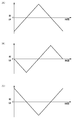
- FIG. 3 is a waveform chart showing a waveform of a pretreatment voltage in the residual chlorine meter according to the first embodiment of the present invention.
- 5 is a voltammogram showing a pretreatment voltage in the residual chlorine meter according to the first embodiment of the present invention.
- the residual chlorine analyzer was used for each of (A) when the pretreatment voltage was swept, (B) when a positive DC voltage was applied as the pretreatment voltage, and (C) when a negative DC voltage was applied as the pretreatment voltage.
- FIG. 5 is a graph showing a voltage when a test solution is immersed between a working electrode and a reference electrode. It is a flow chart which shows operation of a residual chlorine meter of a 2nd embodiment of the present invention.
- FIG. 9 is a waveform chart showing a modification of the pretreatment voltage waveform in the residual chlorine meter according to the first or second embodiment of the present invention.
- FIG. 1 shows the configuration of the residual chlorine meter 1.
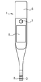
- FIG. 2 shows the appearance of the residual chlorine meter 1.
- the residual chlorine meter 1 is a device for measuring the residual chlorine concentration of a test liquid E such as tap water.
- the residual chlorine meter 1 employs a galvanic method as a method for measuring the residual chlorine concentration.
- the residual chlorine meter 1 includes a working electrode 2, a reference electrode 3, a processing circuit 4, and a power supply circuit 5. Further, the residual chlorine meter 1 includes a housing 6, operation buttons 7, and a display unit 8, as shown in FIG.
- the housing 6 has an elongated shape in the vertical direction as a whole, and the upper part thereof is formed in a substantially rectangular parallelepiped shape.
- the lower portion of the housing 6 is formed in a cylindrical shape having a smaller diameter than the width and thickness of the upper portion.
- the working electrode 2 and the reference electrode 3 are attached to a lower end of the housing 6, and the operation buttons 7 and the display unit 8 are attached to an upper portion of the housing 6.
- the processing circuit 4 and the power supply circuit 5 are housed inside the upper part of the housing 6.
- a battery accommodating portion (not shown) is provided in an upper portion of the housing 6, and a battery 9 is accommodated in the battery accommodating portion.
- the power supply of the residual chlorine meter 1 is not limited to a battery.
- the working electrode 2 is a platinum electrode, a gold electrode, or the like, and is formed, for example, in a linear shape.
- the working electrode 2 may be formed in a disk shape.
- the reference electrode 3 is a silver / silver chloride electrode or the like, and is formed in a linear shape.
- the potential of the reference electrode 3 is set to a reference potential. In the present embodiment, the reference potential is 0V.
- the processing circuit 4 includes a preprocessing voltage application circuit 11 as a preprocessing unit, a measurement circuit 12 as a measurement unit, a switch 13, a microcontroller 14 as a control unit, and a storage circuit 15.
- the pretreatment voltage application circuit 11 is a circuit that applies a pretreatment voltage between the working electrode 2 and the reference electrode 3. As will be described later, the residual chlorine meter 1 applies a voltage between the working electrode 2 and the reference electrode 3 before measuring the residual chlorine concentration of the test liquid E. The process of applying a voltage before this measurement is “pre-processing”, and the voltage applied in this process is “pre-processing voltage”. Further, the preprocessing voltage application circuit 11 has a function of sweeping the preprocessing voltage.
- the measurement circuit 12 is a circuit that measures the residual chlorine concentration of the test solution E based on the voltage between the working electrode 2 and the reference electrode 3. For example, the measurement circuit 12 converts the voltage between the working electrode 2 and the reference electrode 3 from analog to digital and converts the residual chlorine concentration value corresponding to the digitized voltage value to the voltage value between the electrodes and the residual chlorine concentration. The correspondence with the value is specified by a method of referring to a data table in which a value is recorded in advance, or by a method of calculating using a predetermined calculation formula or the like. Then, the measurement circuit 12 outputs the specified residual chlorine concentration value to the microcontroller 14.
- the switch 13 switches between a path for applying a pretreatment voltage between the working electrode 2 and the reference electrode 3 and a path for measuring the residual chlorine concentration based on the voltage between the working electrode 2 and the reference electrode 3. Circuit. Specifically, in the switch 13, when the contact point a and the contact point c are connected, a path for applying a pretreatment voltage from the pretreatment voltage application circuit 11 to between the working electrode 2 and the reference electrode 3 is formed. You. On the other hand, when the contact b and the contact c are connected in the switch 13, a path for measuring the residual chlorine concentration by the measuring circuit 12 based on the voltage between the working electrode 2 and the reference electrode 3 is formed.
- the microcontroller 14 is a device that controls the preprocessing voltage application circuit 11, the measurement circuit 12, and the switch 13, and includes an arithmetic processing circuit and the like.
- the microcontroller 14 outputs a switching control signal to the switch 13, and the switch 13 can switch between a state in which the contacts a and c are connected and a state in which the contacts b and c are connected. it can.
- the microcontroller 14 can output a preprocessing control signal to the preprocessing voltage application circuit 11 and start outputting the preprocessing voltage.
- the microcontroller 14 can output a measurement control signal to the measurement circuit 12 and start measuring the residual chlorine concentration.
- the microcontroller 14 when the user presses the operation button 7, the microcontroller 14 starts the pre-processing in response to the operation button 7, and performs the measurement processing after the pre-processing is completed. Further, the microcontroller 14 can display the measurement result of the residual chlorine concentration on the display unit 8.
- the display unit 8 is, for example, a liquid crystal display.
- the storage circuit 15 includes a semiconductor storage element, and stores data used for processing by the microcontroller 14 and the like.
- the power supply circuit 5 is a circuit that supplies the power obtained from the battery 9 to the preprocessing voltage application circuit 11, the measurement circuit 12, the switch 13, the microcontroller 14, the storage circuit 15, the operation button 7, and the display unit 8. is there.
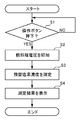
- FIG. 3 shows the operation of the residual chlorine meter 1.
- the user puts the lower end of the residual chlorine meter 1 into the test liquid E, and immerses the working electrode 2 and the reference electrode 3 in the test liquid E. . Then, the user presses the operation button 7 with the working electrode 2 and the reference electrode 3 immersed in the test liquid E.
- step S1 YES
- step S2 pretreatment step
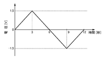
- FIG. 4 shows the waveform of the pre-processing voltage.
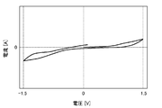
- FIG. 5 shows a voltammogram of the pretreatment voltage.
- the preprocessing voltage application circuit 11 sweeps the preprocessing voltage, for example, as shown in FIGS. That is, the pre-processing voltage application circuit 11 sweeps the pre-processing voltage around 0 V so that the plus side amplitude and the minus side amplitude are equal to each other. In the present embodiment, for example, the peak value on the plus side of the pre-processing voltage is 1.5V, and the peak value on the minus side is -1.5V.
- the pre-processing voltage application circuit 11 sweeps the pre-processing voltage at a constant speed. In the present embodiment, for example, the sweep speed of the preprocessing voltage is 0.5 V / sec.
- the preprocessing voltage application circuit 11 sweeps the preprocessing voltage in a fixed pattern.
- the pattern of the pre-processing voltage in the present embodiment is as follows. That is, as shown in FIG. 4, the voltage value at the start of the pre-processing voltage is 0V. Subsequently, the pretreatment voltage increases from 0V at a rate of 0.5V / sec for 3 seconds. As a result, the voltage value of the pretreatment voltage reaches 1.5V. Subsequently, the pretreatment voltage is reduced from 1.5V to 0.5V / sec for 6 seconds. As a result, the voltage value of the pretreatment voltage reaches -1.5V. Subsequently, the pretreatment voltage increases for 3 seconds at a rate of -1.5V to 0.5V / sec.
- the voltage value of the pre-processing voltage becomes 0V.
- the preprocessing voltage application circuit 11 stops outputting the preprocessing voltage after sweeping the preprocessing voltage in such a pattern for 12 seconds.
- the waveform of the pre-processing voltage is a waveform corresponding to one cycle of the triangular wave.
- the microcontroller 14 After the output of the preprocessing voltage is stopped, the microcontroller 14 outputs a switching control signal to the switch 13 and connects the contact b and the contact c of the switch 13. Subsequently, the microcontroller 14 outputs a measurement control signal to the measurement circuit 12, and starts measuring the residual chlorine concentration of the test solution E.
- the measurement circuit 12 measures the residual chlorine concentration of the test solution E based on the voltage between the working electrode 2 and the reference electrode 3, and outputs the measured residual chlorine concentration value to the microcontroller 14 (Step S3: Measurement) Process).
- the microcontroller 14 displays the measurement result of the residual chlorine concentration by the measurement circuit 12 on the display unit 8 (Step S4).
- the pretreatment voltage is applied between the working electrode 2 and the reference electrode 3 so that the residual chlorine concentration performed last time or earlier is measured.
- the residual chlorine concentration By the measurement, at least a part of the oxidation-reduction reaction product and the like attached to the working electrode 2 can be removed.
- By measuring the residual chlorine concentration after the application of the pretreatment voltage it is possible to suppress a decrease in the measurement accuracy of the residual chlorine concentration due to the adhesion of the oxidation-reduction reaction product and the like to the working electrode 2. it can.
- This operational effect of the residual chlorine meter 1 was confirmed by several experiments described below.
- the same working electrode, reference electrode, and measurement circuit as those of the residual chlorine meter 1 according to the first embodiment of the present invention are provided, and a voltage value between the working electrode and the reference electrode is output to the outside as data.
- An experimental galvanic residual chlorine meter provided with a function capable of performing the measurement was used. In performing the first experiment, such a residual chlorine meter is used.
- the working electrode and the reference electrode are immersed in a test solution such as tap water for ten and several seconds and then taken out of the test solution. I prepared six items that had been left for about a year. These six residual chlorine meters are referred to as residual chlorine meters M1 to M6.
- test liquid pure water, adjusted water whose residual chlorine concentration was adjusted to about 0.2 mg / L, adjusted water whose residual chlorine concentration was adjusted to about 0.4 mg / L, And conditioned water whose residual chlorine concentration was adjusted to about 0.8 mg / L was prepared. Then, using the residual chlorine meters M1 to M3, the voltage at the time of immersing the test liquid between the working electrode and the reference electrode when neither the wiping of the working electrode nor the application of the pretreatment voltage is performed, and the rubbing of the working electrode. The voltage when the test liquid was immersed between the working electrode and the reference electrode when wiping was performed was measured.
- the voltage at the time of immersing the test liquid between the working electrode and the reference electrode and the pretreatment voltage when neither the wiping of the working electrode nor the application of the pretreatment voltage is performed.
- the voltage when the test solution was immersed between the working electrode and the reference electrode when the voltage was applied was measured.
- Step 1 the working electrode and the reference electrode of the residual chlorine meter M1 are immersed in the test liquid, and the operation of measuring the voltage between the two electrodes in this state is continuously and sequentially performed on the above four test liquids.
- Step 1-2 the working electrode of the residual chlorine meter M1 was sufficiently wiped with a melamine sponge or the like.
- Step 1-3 the working electrode and the reference electrode of the residual chlorine meter M1 are immersed in the test liquid, and the operation of measuring the voltage between both electrodes in that state is sequentially performed on the above four test liquids.
- steps 1-1 to 1-3 were performed using the residual chlorine meter M2, and then steps 1-1 to 1-3 were performed using the residual chlorine meter M3.
- the working electrode and the reference electrode of the residual chlorine meter M4 were immersed in the test liquid, and the operation of measuring the voltage between the two electrodes in that state was continuously and sequentially performed on the above four test liquids. (Step 1-4).
- the working electrode and the reference electrode of the residual chlorine meter M4 are immersed in one of the above four types of test liquids, and in this state, the operation of the residual chlorine meter M4 is performed using an external device such as a potentiostat.
- a pretreatment voltage of the sweep pattern shown in FIG. 4 was applied between the electrode and the reference electrode (Step 1-5).
- Step 1-6 steps 1-4 to 1-6 were performed using the residual chlorine meter M5, and then steps 1-4 to 1-6 were performed using the residual chlorine meter M6.
- Steps 1-1 to 1-3 are performed three times using three residual chlorine meters M1 to M3, and steps 1-4 to 1-6 are performed three times using three residual chlorine meters M4 to M6. The reason for this is to confirm the accuracy of the experiment.
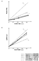
- FIG. 6 (A) shows the measurement results of the voltage between the working electrode and the reference electrode of each of the residual chlorine meters M1 to M3 obtained in the step 1-1. These are the measurement results of the voltage when the test liquid is immersed between the working electrode and the reference electrode of each of the residual chlorine meters M1 to M3 when neither the working electrode nor the pretreatment voltage is applied.
- the broken line in FIG. 6A indicates the voltage value (upper limit voltage value U) when the test liquid is immersed between the working electrode and the reference electrode, which corresponds to the upper limit of the error range allowed for the residual chlorine meter. Is shown.
- 6A indicates the voltage value (lower limit voltage value) when the test liquid is immersed between the working electrode and the reference electrode, corresponding to the lower limit of the error range allowable as the residual chlorine meter. L).
- 6 (B), 7 (A) and 7 (B), a broken line indicating the upper limit voltage value U and a two-dot chain line indicating the lower limit voltage value L are also drawn.
- FIG. 6 (A) the voltages between the working electrode and the reference electrode of the residual chlorine meters M1 to M3 were all different in the residual chlorine concentrations of the four test liquids used in this experiment. It is below the lower limit voltage value L. That is, when the residual chlorine concentration of the test solution is measured without wiping the working electrode or applying the pretreatment voltage, a correct measurement result of the residual chlorine concentration cannot be obtained.
- FIG. 6 (B) shows the measurement results of the voltage between the working electrode and the reference electrode of each of the residual chlorine meters M1 to M3 obtained in step 1-3. These are the measurement results of the voltage when the test liquid is immersed between the working electrode and the reference electrode of each of the residual chlorine meters M1 to M3 when the working electrode is wiped.
- the voltages between the working electrode and the reference electrode of the residual chlorine meters M1 to M3 were all different in the residual chlorine concentrations of the four test liquids used in this experiment. It is not less than the lower limit voltage value L and not more than the upper limit voltage value U. That is, when the residual chlorine concentration of the test solution is measured after wiping the working electrode, a correct measurement result of the residual chlorine concentration can be obtained.
- the residual electrode was attached to the working electrode by the previous or earlier measurement of the residual chlorine concentration. It is possible to remove at least a part of the oxidation-reduction reaction products, etc., and measure the residual chlorine concentration after wiping, so that the measurement of the residual chlorine concentration caused by the adhesion of the oxidation-reduction reaction products, etc. to the working electrode can be performed. A decrease in accuracy can be suppressed.
- FIG. 7A shows the measurement results of the voltage between the working electrode and the reference electrode of each of the residual chlorine meters M4 to M6 obtained in the step 1-4. These are the measurement results of the voltage when the test liquid is immersed between the working electrode and the reference electrode of each of the residual chlorine meters M4 to M6 when neither the working electrode nor the pretreatment voltage is applied.
- the voltages between the working electrode and the reference electrode of the residual chlorine meters M4 to M6 were all different in the residual chlorine concentrations of the four test liquids used in this experiment. It is below the lower limit voltage value L. That is, when the residual chlorine concentration of the test solution was measured without wiping the working electrode or applying the pretreatment voltage, it was found that the correct measurement result of the residual chlorine concentration could not be obtained. Each was also confirmed.
- FIG. 7 (B) shows the measurement results of the voltage between the working electrode and the reference electrode of each of the residual chlorine meters M4 to M6 obtained in step 1-6. These are the measurement results of the voltage when the test liquid is immersed between the working electrode and the reference electrode of each of the residual chlorine meters M4 to M6 when the pretreatment voltage is applied.
- the voltages between the working electrode and the reference electrode of the residual chlorine meters M4 to M6 were all different in the residual chlorine concentrations of the four test liquids used in this experiment. It is not less than the lower limit voltage value L and not more than the upper limit voltage value U. That is, when the residual chlorine concentration of the test solution is measured after applying the pretreatment voltage, a correct measurement result of the residual chlorine concentration can be obtained.
- the residual chlorine concentration performed last time or earlier is applied.
- the residual chlorine concentration can be measured after application of the pretreatment voltage, so that the working electrode such as the oxidation-reduction reaction product can be removed. It is possible to suppress a decrease in the measurement accuracy of the residual chlorine concentration due to the adhesion to the substrate.
- the residual chlorine concentration of the test liquid E was measured after the pretreatment voltage was applied between the working electrode 2 and the reference electrode 3. By performing the measurement, it was confirmed that a decrease in the measurement accuracy of the residual chlorine concentration can be suppressed to the same extent as when measuring the residual chlorine concentration of the test solution E after wiping the working electrode 2.
- the residual chlorine meter 1 of the first embodiment of the present invention by applying a pretreatment voltage between the working electrode 2 and the reference electrode 3 before measuring the residual chlorine concentration of the test solution E, It is possible to suppress a decrease in the measurement accuracy of the residual chlorine concentration due to the redox reaction product and the like adhering to the working electrode 2. Therefore, the work of wiping the redox reaction products and the like adhered to the working electrode 2 with a soft cloth or melamine sponge before measurement can be eliminated. Further, in order to polish the working electrode 2 with the polishing beads, a large-scale device such as a device for moving the working electrode 2 in a circular motion by a motor and a device for pouring the test liquid E into a container containing the polishing beads is unnecessary. Thus, it is possible to prevent the residual chlorine meter 1 from being enlarged, complicated, and expensive.
- the working electrode and the reference electrode were immersed in a test liquid such as tap water for ten and several seconds, and then taken out of the test liquid and left as it was for about one year.
- These three residual chlorine meters are referred to as residual chlorine meters M11 to M13.
- the working electrode is polished, and the pretreatment voltage is applied between the working electrode and the reference electrode. The surface analysis of the working electrode was carried out without any.
- the working electrode was polished with an abrasive (diamond paste) (polishing treatment), and immediately thereafter. The surface of the working electrode was analyzed. Further, with respect to the residual chlorine meter M13, the working electrode and the reference electrode were immersed in tap water for ten and several seconds, and a pretreatment voltage of the sweep pattern shown in FIG. 4 was applied between the working electrode and the reference electrode during the immersion. Immediately after the immersion, the surface of the working electrode was analyzed.
- FIG. 8 shows the results of surface analysis of the working electrodes of the residual chlorine meters M11 to M13.
- the ratio of platinum (Pt) on the surface of the working electrode of the residual chlorine meter M11 is 11.1%, while the ratio of platinum on the surface of the working electrode of the residual chlorine meter M12 is 36.3. %. That is, the ratio of platinum on the surface of the working electrode of the residual chlorine meter M12 is larger than the ratio of platinum on the surface of the working electrode of the residual chlorine meter M11. This means that a part of the oxidation-reduction reaction product and the like attached to the surface of the working electrode was removed by performing the polishing treatment on the working electrode.
- the ratio of platinum on the surface of the working electrode of the residual chlorine meter M11 is 11.1%, whereas the ratio of platinum on the surface of the working electrode of the residual chlorine meter M13 is 22.4%. It is. That is, the ratio of platinum on the surface of the working electrode of the residual chlorine meter M13 is larger than the ratio of platinum on the surface of the working electrode of the residual chlorine meter M11. This means that by applying a pretreatment voltage between the working electrode and the reference electrode, a part of the oxidation-reduction reaction product and the like attached to the surface of the working electrode was removed.
- the ratio of platinum on the surface of the working electrode of the residual chlorine meter M13 is close to the ratio of platinum on the surface of the working electrode of the residual chlorine meter M12. This is because the effect similar to the effect of removing the oxidation-reduction reaction products and the like obtained by performing the polishing treatment on the working electrode of the residual chlorine meter is caused by the pretreatment voltage between the working electrode and the reference electrode of the residual chlorine meter. Is obtained by applying.
- the same working electrode, reference electrode, and measurement circuit as those of the residual chlorine meter 1 of the first embodiment of the present invention were provided, and the voltage between the working electrode and the reference electrode was measured.
- An experimental galvanic residual chlorine meter provided with a function capable of outputting values as data to the outside was used.
- such a residual chlorine meter was used.
- the working electrode and the reference electrode were immersed in a test solution such as tap water for several tens of seconds, then taken out of the test solution and left as it was. Ten items left for about a year were prepared. These ten residual chlorine meters are referred to as residual chlorine meters M21 to M30.
- test liquid conditioned water whose residual chlorine concentration was adjusted to about 0.2 mg / L, conditioned water whose residual chlorine concentration was adjusted to about 0.4 mg / L, and residual chlorine Conditioned water having a concentration adjusted to about 0.8 mg / L was prepared. Then, using the residual chlorine meters M21 to M25, the voltage at the time of immersing the test liquid between the working electrode and the reference electrode after wiping the working electrode was measured a plurality of times at predetermined time intervals. . Further, using a residual chlorine meter M26 to M30, the voltage at the time of immersing the test liquid between the working electrode and the reference electrode after applying the pretreatment voltage was measured a plurality of times at predetermined time intervals.
- Step 2-1 the working electrode of the residual chlorine meter M21 was sufficiently wiped with a melamine sponge or the like.
- the working electrode and the reference electrode of the residual chlorine meter M21 are immersed in the test liquid, and the operation of measuring the voltage between both electrodes in that state is sequentially performed on the above three test liquids.
- Step 2-2 the residual chlorine meter M21 was immediately taken out of the test solution and left in the atmosphere.
- steps 2-1 to 2-3 were sequentially and sequentially performed using the residual chlorine meters M22 to M25.
- Steps 2-2 and 2-3 alone were performed sequentially and sequentially.
- the working electrode and the reference electrode of the residual chlorine meter M26 are immersed in any of the above three types of test liquids, and in this state, the working electrode of the residual chlorine meter M26 is measured using an external device such as a potentiostat.
- a pretreatment voltage of the sweep pattern shown in FIG. 4 was applied between the reference electrode and the reference electrode (step 2-4).
- the working electrode and the reference electrode of the residual chlorine meter M26 are immersed in the test liquid, and the operation of measuring the voltage between both electrodes in that state is performed on the above three test liquids. This was performed sequentially and continuously (step 2-5).
- the residual chlorine meter M26 was immediately taken out of the test solution and left in the atmosphere (Step 2-6).
- steps 2-4 to 2-6 were sequentially and continuously performed using the residual chlorine meters M27 to M30.
- steps 2-4 to 2-6 were sequentially and continuously performed using the residual chlorine meters M27 to M30.
- steps 2-4 to 2-6 were sequentially and continuously performed using the residual chlorine meters M27 to M30.
- steps 2-4 to 2-6 were sequentially and continuously performed using the residual chlorine meters M27 to M30.
- steps 2-4 to 2-6 were sequentially and continuously performed using the residual chlorine meters M27 to M30.
- steps 2-4 to 2-6 were sequentially and continuously performed using the residual chlorine meters M27 to M30.
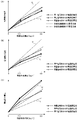
- FIG. 9 (A) shows the average value of the voltage at the time of immersing the test liquid between the working electrode and the reference electrode of each of the residual chlorine meters M21 to M25 obtained in the step 2-2, for each number of elapsed days, and It is calculated for each residual chlorine concentration of the test liquid, and the change in the average value according to the number of elapsed days is drawn.
- FIG. 9 (B) shows the average value of the voltage at the time of immersing the test liquid between the working electrode and the reference electrode of each of the residual chlorine meters M26 to M30 obtained in the step 2-5. Calculated for each residual chlorine concentration in the test liquid, and the change of the average value according to the number of elapsed days is drawn.
- the 9A and 9B is a voltage value at the time of immersing the test liquid between the working electrode and the reference electrode, which corresponds to the lower limit of the allowable error range of the residual chlorine meter.
- (Lower limit voltage values La, Lb, Lc) are shown for each residual chlorine concentration.
- the lower limit voltage value La is a lower limit voltage value when the working electrode and the reference electrode are immersed in a test solution having a residual chlorine concentration of about 0.2 mg / L.
- the lower limit voltage value Lb is a lower limit voltage value when the working electrode and the reference electrode are immersed in a test liquid having a residual chlorine concentration of about 0.4 mg / L.
- the lower limit voltage value Lc is a lower limit voltage value when the working electrode and the reference electrode are immersed in a test liquid having a residual chlorine concentration of about 0.8 mg / L.
- the residual chlorine meters M26 to M30 to which the pretreatment voltage has been applied between the working electrode and the reference electrode have the working electrode and the reference electrode on the starting day of the second experiment.
- the voltage at the time of immersion in the test solution between the working electrode and the reference electrode is changed to the lower limit voltage values La and Lb for all the residual chlorine concentrations.
- Lc. 9A and 9B when the pretreatment voltage is applied between the working electrode of the residual chlorine meter and the reference electrode, the working electrode of the residual chlorine meter is rubbed. Compared to wiping, the duration of the effect of suppressing a decrease in the measurement accuracy of the residual chlorine concentration due to the redox reaction products and the like adhering to the working electrode is longer.
- the oxidation-reduction reaction products and the like are reduced. It was confirmed that the effect of suppressing a decrease in the measurement accuracy of the residual chlorine concentration due to the attachment to the working electrode 2 can be maintained for a long time.
- the same working electrode, reference electrode, and measurement circuit as those of the residual chlorine meter 1 of the first embodiment of the present invention were provided, and the voltage between the working electrode and the reference electrode was measured.
- An experimental galvanic residual chlorine meter provided with a function capable of outputting values as data to the outside was used.
- such a residual chlorine meter is used.
- the working electrode and the reference electrode are immersed in a test solution such as tap water for ten and several seconds and then taken out of the test solution. Nine items were left for about a year. These nine residual chlorine meters are referred to as residual chlorine meters M41 to M49.
- the working electrode and the reference electrode of the residual chlorine meter M41 are immersed in any of the above three types of test liquids, and in this state, the working electrode of the residual chlorine meter M41 is measured using an external device such as a potentiostat.
- a pretreatment voltage of the sweep pattern shown in FIG. 4 was applied between the reference electrode and the reference electrode (step 3-1).
- the positive peak value of the pretreatment voltage was 1.5 V
- the negative peak value was -1.5 V
- the application time was 12 seconds.
- steps 3-1 and 3-2 were performed using the residual chlorine meter M42, and then steps 3-1 and 3-2 were performed using the residual chlorine meter M43.
- the working electrode and the reference electrode of the residual chlorine meter M44 are immersed in any of the above three types of test liquids, and in this state, the working electrode of the residual chlorine meter M44 is measured using an external device such as a potentiostat.
- a DC voltage of 1.5 V was applied as a pretreatment voltage for 12 seconds between the reference electrode and the reference electrode (step 3-3).
- the working electrode and the reference electrode of the residual chlorine meter M44 are immersed in the test liquid, and the operation of measuring the voltage between both electrodes in that state is performed on the above three test liquids. This was performed sequentially and continuously (step 3-4).
- steps 3-3 and 3-4 were performed using the residual chlorine meter M45, and then steps 3-3 and 3-4 were performed using the residual chlorine meter M46.
- the working electrode and the reference electrode of the residual chlorine meter M47 are immersed in any of the above three types of test liquids, and in this state, the working electrode of the residual chlorine meter M47 is measured using an external device such as a potentiostat.
- a DC voltage of -1.5 V was applied as a pretreatment voltage for 12 seconds between the first electrode and the reference electrode (step 3-5).
- the working electrode and the reference electrode of the residual chlorine meter M47 are immersed in the test liquid, and the operation of measuring the voltage between both electrodes in that state is performed on the above three test liquids. This was performed sequentially and continuously (step 3-6).
- steps 3-5 and 3-6 were performed using a residual chlorine meter M48, and then steps 3-5 and 3-6 were performed using a residual chlorine meter M49.
- FIG. 10 (A) shows the measurement results of the voltage when the test liquid is immersed between the working electrode and the reference electrode of each of the residual chlorine meters M41 to M43 obtained in step 3-2. These are the measurement results of the voltage when the test solution is immersed between the working electrode and the reference electrode of the residual chlorine meter when the pretreatment voltage is swept.
- the broken line in FIG. 10A corresponds to the upper limit of the error range allowable as the residual chlorine meter, and the voltage value (upper limit voltage value U) when the test liquid is immersed between the working electrode and the reference electrode. Is shown.
- 10A indicates the voltage value (lower limit voltage value) when the test liquid is immersed between the working electrode and the reference electrode, which corresponds to the lower limit of the error range allowed for the residual chlorine meter. L).
- the dashed line in FIG. 10A indicates a voltage value exactly intermediate between the upper limit voltage value U and the lower limit voltage value L.
- 10 (B) and 10 (C) also show a dashed line indicating the upper limit voltage value U, a two-dot chain line indicating the lower limit voltage value L, and an intermediate point between the upper limit voltage value U and the lower limit voltage value L.
- the chain line is drawn. As can be seen from FIG.
- the voltages between the working electrode and the reference electrode of the residual chlorine meters M41 to M43 were all different in the residual chlorine concentrations of the three test liquids used in this experiment. , And not less than the lower limit voltage value L and not more than the upper limit voltage value U. Further, most of the voltage between the working electrode and the reference electrode of the residual chlorine meters M41 to M43 is concentrated near the middle between the lower limit voltage value L and the upper limit voltage value U.
- FIG. 10 (B) shows the measurement results of the voltage when the test liquid is immersed between the working electrode and the reference electrode of each of the residual chlorine meters M44 to M46 obtained in step 3-4. These are the measurement results of the voltage when the test liquid is immersed between the working electrode and the reference electrode of the residual chlorine meter when a positive DC voltage is applied as the pretreatment voltage.
- the voltages between the working electrode and the reference electrode of the residual chlorine meters M44 to M46 were all different in the residual chlorine concentrations of the three test liquids used in this experiment.
- the lower limit voltage value L and not more than the upper limit voltage value U part of the voltage between the working electrode and the reference electrode of the residual chlorine meters M44 to M46 is lower than the intermediate value between the lower limit voltage value L and the upper limit voltage value U and is close to the lower limit voltage value L. Has become.
- FIG. 10 (C) shows the measurement results of the voltage when the test liquid is immersed between the working electrode and the reference electrode of each of the residual chlorine meters M47 to M49 obtained in step 3-6. These are the measurement results of the voltage when the test liquid is immersed between the working electrode and the reference electrode of the residual chlorine meter when a negative DC voltage is applied as the pretreatment voltage. As can be seen from FIG. 10C, a part of the voltage between the working electrode and the reference electrode of the residual chlorine meters M47 to M49 exceeds the upper limit voltage value U.
- the measurement accuracy of the residual chlorine concentration of the test liquid E is further improved by sweeping the pretreatment voltage as in the residual chlorine meter 1 according to the first embodiment of the present invention. It was confirmed that it was possible.
- the above-described residual chlorine meter 1 of the first embodiment of the present invention applies a pretreatment voltage before the measurement each time the measurement of the residual chlorine concentration of the test liquid E is performed once.
- the residual chlorine meter according to the second embodiment of the present invention applies the pretreatment voltage before the measurement once every two or more predetermined times of measuring the residual chlorine concentration of the test solution E. Do.
- the hardware configuration of the residual chlorine meter according to the second embodiment is the same as the hardware configuration of the residual chlorine meter 1 according to the first embodiment shown in FIG. Further, the microcontroller 14 of the residual chlorine meter according to the second embodiment has a function of controlling the application of the pretreatment voltage based on the number of times of measuring the residual chlorine concentration. That is, the microcontroller 14 of the residual chlorine meter of the second embodiment determines whether the number of times of measurement of the residual chlorine concentration after application of the pretreatment voltage is equal to or greater than a predetermined number, and the number of measurements is equal to or greater than the predetermined number.
- the pretreatment voltage is applied before the next measurement of the residual chlorine concentration, and when the number of measurements is less than the predetermined number, the pretreatment voltage is applied before the next measurement of the residual chlorine concentration.
- the pre-processing voltage application circuit 11 is controlled so as not to be present.
- the storage circuit 15 of the residual chlorine meter according to the second embodiment stores a measurement count value which is a count value indicating the number of measurements of the residual chlorine concentration after the application of the pretreatment voltage. In the present embodiment, the initial value of the number of times of measurement is 0.
- FIG. 11 shows the operation of the residual chlorine meter according to the second embodiment of the present invention.
- the microcontroller 14 detects the press of the operation button 7 (step S11: YES), Subsequently, the measurement count value is read from the storage circuit 15 (step S12). Subsequently, the microcontroller 14 determines whether the read measurement count value is equal to or greater than a preset count reference value (step S13).
- the number-of-times reference value is, for example, 2 or more and is set in advance. Note that the user may be allowed to set the number-of-times reference value arbitrarily.
- step S13 If the result of this determination is that the number of times of measurement is equal to or greater than the reference value of number of times (step S13: YES), the microcontroller 14 sets the number of times of measurement to an initial value (step S14). Subsequently, the microcontroller 14 controls the switch 13 to connect the contact a and the contact c of the switch 13, and then controls the pretreatment voltage application circuit 11 to operate the pretreatment voltage working electrode 2. The application between the first electrode and the reference electrode 3 is started (step S15: pre-processing step). The preprocessing voltage application circuit 11 starts outputting the preprocessing voltage under the control of the microcontroller 14, sweeps the preprocessing voltage for 12 seconds in the sweep pattern shown in FIG. 4, and then stops applying the preprocessing voltage.
- the microcontroller 14 controls the switch 13 to connect the contact b and the contact c of the switch 13, and then controls the measurement circuit 12 to perform the test.
- the measurement of the residual chlorine concentration of the liquid E is started.
- the measuring circuit 12 measures the residual chlorine concentration of the test solution E, and outputs the measured residual chlorine concentration value to the microcontroller 14 (Step S16: measuring step).
- step S13 determines whether the number of times of measurement is not equal to or more than the above number of times reference. If the result of the determination in step S13 is that the number of times of measurement is not equal to or more than the above number of times reference (step S13: NO), the microcontroller 14 sets the number of times of measurement to an initial value and applies a pre-processing voltage. Without performing such control, the contact b and the contact c of the switch 13 are immediately connected, and the measurement circuit 12 starts measuring the residual chlorine concentration of the test solution E. The measuring circuit 12 measures the residual chlorine concentration of the test solution E, and outputs the measured residual chlorine concentration value to the microcontroller 14 (Step S16: measuring step).
- the microcontroller 14 displays the measurement result of the residual chlorine concentration output from the measurement circuit 12 on the display unit 8 (Step S17). Subsequently, the microcontroller 14 increases the measurement count value stored in the storage circuit 15 by 1 (step S18).
- the reference number of times is set to 5, and the measurement of the residual chlorine concentration was performed six times after the pretreatment voltage was applied.
- the first measurement of the residual chlorine concentration is performed immediately after the application of the pretreatment voltage, so that the pretreatment voltage is applied immediately before the first measurement of the residual chlorine concentration.
- the second, third, fourth, and fifth measurement of the residual chlorine concentration no pretreatment voltage is applied.
- a pretreatment voltage is applied.
- the frequency of application of the pretreatment voltage is reduced, so that the residual chlorine concentration caused by the redox reaction products and the like adhering to the working electrode 2 is reduced.
- the measurement work can be sped up while suppressing the decrease in the measurement accuracy of, and the power consumption can be reduced to extend the life of the battery 9.
- the case of applying a pre-processing voltage of a triangular wave as shown in FIG. 4 has been described as an example.
- the phase of the pre-processing voltage, the sweep speed, the magnitude of the peak value, the number of cycles, , Waveform and the like are not limited.
- the phase of the pre-processing voltage (the voltage for starting the sweep and the voltage for ending the sweep) may be changed.
- the sweep speed of the pre-processing voltage is 0.5 V / sec.
- the sweep speed of the pre-processing voltage may be slower or faster.
- the plus side peak value of the preprocessing voltage is set to 1.5 V, and the minus side peak value is set to ⁇ 1.5 V.
- each peak value can be appropriately adjusted.
- the pre-processing voltage for one cycle of the waveform is applied, but a pre-processing voltage for two or more cycles of the waveform may be applied.
- the waveform of the preprocessing voltage may be a sine wave.
- the pre-processing voltage may be a positive or negative DC voltage.
- a DC pretreatment voltage when a DC pretreatment voltage is applied, a reference is made to the working electrode of the residual chlorine meter when measuring the residual chlorine concentration as compared with the case where the pretreatment voltage is swept. Although the voltage between the electrodes may become unstable, the reduction of the measurement accuracy of the residual chlorine concentration is suppressed as compared with the case where the pretreatment voltage is not applied and the working electrode is not rubbed. Can be.
- the operation automatically shifts from the application of the pretreatment voltage to the measurement of the residual chlorine concentration. It may be. Further, only the pre-processing voltage may be applied according to the operation of the user.
- a bias voltage may be applied between the working electrode 2 and the reference electrode 3 by the measurement circuit 12. This bias voltage is different from the voltage applied to measure the residual chlorine concentration in the polarographic residual chlorine meter.
- the present invention is applied to a portable type residual chlorine meter as shown in FIG. 2 as an example.
- the present invention can also be applied to a stationary type residual chlorine analyzer that periodically measures the residual chlorine concentration of tap water that is fixed to a water tank or flowing in a pipe or stored in a water tank.
- whether to apply the pretreatment voltage or not is determined based on the number of measurements of the residual chlorine concentration after the application of the pretreatment voltage.
- the number-of-times reference value may be changed based on a measurement value obtained by measuring the residual chlorine concentration actually performed after the application of the pretreatment voltage. For example, as the measured value obtained by measuring the residual chlorine concentration increases (residual chlorine concentration increases), the reference number of times is decreased, and the measured value obtained by measuring the residual chlorine concentration decreases (residual chlorine concentration decreases).
- the number-of-times reference value may be increased as the value becomes thinner. This makes it possible to determine an appropriate timing for applying the pretreatment voltage, taking into account that the ease with which the redox reaction products and the like adhere to the electrode varies depending on the residual chlorine concentration.
- the residual chlorine meter according to the second embodiment determines whether or not to apply the pretreatment voltage based on the number of times of measuring the residual chlorine concentration after the application of the pretreatment voltage.
- the present invention is not limited to this. Whether or not to apply the pre-processing voltage may be determined based on the elapsed time after the application of the pre-processing voltage.
- the microcontroller 14 determines whether or not the elapsed time since the application of the pre-processing voltage is equal to or longer than a predetermined reference time, and when the elapsed time is equal to or longer than the reference time, the measurement circuit 12
- the pretreatment voltage is applied before the measurement of the residual chlorine concentration according to the above, and when the elapsed time is less than the reference time, the pretreatment voltage is not applied before the measurement of the residual chlorine concentration by the measurement circuit 12.
- the pre-processing voltage application circuit 11 is controlled. As shown in FIG. 9 (B), when 21 days have passed since the application of the pretreatment voltage, the voltage at the time of immersion of the test solution between the working electrode and the reference electrode was correctly measured for the residual chlorine concentration.
- a reference time serving as a criterion for the determination is determined.
- the temperature may be changed based on a measurement value obtained by measuring the residual chlorine concentration actually performed after the application of the pretreatment voltage.
- the reference time may be shortened as the measurement value obtained by measuring the residual chlorine concentration increases, and the reference time may be increased as the measurement value obtained by measuring the residual chlorine concentration decreases. . This makes it possible to determine an appropriate timing for applying the pretreatment voltage, taking into account that the ease with which the redox reaction products and the like adhere to the electrode varies depending on the residual chlorine concentration.
- whether or not to apply the pretreatment voltage is determined by the number of measurements of the residual chlorine concentration after the application of the pretreatment voltage and after the application of the pretreatment voltage. The determination may be based on both elapsed times. For example, the microcontroller 14 of the residual chlorine meter determines that the number of times of measurement of the residual chlorine concentration is equal to or greater than the reference number and that the elapsed time is equal to or greater than the predetermined reference time since the application of the pretreatment voltage. If either one of the conditions is satisfied, it is determined that the preprocessing voltage is to be applied. This makes it possible to determine an appropriate timing for applying the pretreatment voltage in consideration of the actual use state of the residual chlorine meter.
- the present invention can be appropriately changed within a scope not contrary to the gist or idea of the invention which can be read from the claims and the entire specification, and a residual chlorine meter and a residual chlorine concentration measuring method with such a change are also provided. It is also included in the technical concept of the present invention.
Landscapes
- Chemical & Material Sciences (AREA)
- Life Sciences & Earth Sciences (AREA)
- Health & Medical Sciences (AREA)
- Physics & Mathematics (AREA)
- Chemical Kinetics & Catalysis (AREA)
- Electrochemistry (AREA)
- Molecular Biology (AREA)
- Analytical Chemistry (AREA)
- Biochemistry (AREA)
- General Health & Medical Sciences (AREA)
- General Physics & Mathematics (AREA)
- Immunology (AREA)
- Pathology (AREA)
- Investigating Or Analyzing Non-Biological Materials By The Use Of Chemical Means (AREA)
- Water Treatment By Electricity Or Magnetism (AREA)
Abstract
酸化還元反応生成物等が作用電極に付着することに起因する残留塩素濃度の測定精度の低下を、利用者に手間をかけることなく、かつ残留塩素計の大型化、複雑化または高価格化を招くことなく抑制する。残留塩素計1は、作用電極2と参照電極3とを被検液Eに浸漬させ、作用電極2と参照電極3との間の電圧に基づいて被検液Eの残留塩素濃度を測定する測定回路12と、作用電極2と参照電極3との間に前処理電圧を印加する前処理電圧印加回路11と、前処理電圧の印加後、前処理電圧の印加を停止し、その後、被検液Eの残留塩素濃度の測定を行うように測定回路12および前処理電圧印加回路11を制御するマイクロコントローラー14とを備えている。また、前処理電圧印加回路11は前処理電圧を掃引することが好ましい。
Description
本発明は、水道水等の被検液の残留塩素濃度を測定する残留塩素計および残留塩素濃度測定方法に関する。
無試薬型残留塩素計としてガルバニ方式の残留塩素計が知られている。ガルバニ方式の残留塩素計では、白金電極または金電極を作用電極として用い、銀/塩化銀電極を参照電極として用い、両電極を水道水等の被検液に浸漬させ、両電極間の電圧に基づいて被検液の残留塩素濃度を測定する。カルバニ方式の残留塩素計の測定原理は概ね次の通りである。すなわち、作用電極および参照電極を被検液に浸漬させると、酸化還元反応により電極間に電流が流れ、電極間に電位差が生じる。この電極間の電位差は、被検液の残留塩素濃度に応じて異なる。したがって、電極間の電位差(電圧)に基づいて被検液の残留塩素濃度を測定することができる。
また、無試薬型の他の方式の残留塩素計としてポーラログラフ方式の残留塩素計が知られている。ポーラログラフ方式の残留塩素計も、多くの場合、ガルバニ方式の残留塩素計と同様に、白金電極または金電極を作用電極として用い、銀/塩化銀電極を対極として用い、両電極を水道水等の被検液に浸漬させて被検液の残留塩素濃度の測定を行う。しかしながら、ポーラログラフ方式の残留塩素計では、ガルバニ方式の残留塩素計とは異なり、電極間に電圧を印加し、その状態で、電極間の電流値に基づいて被検液の残留塩素濃度を測定する。ポーラログラフ方式の残留塩素計の測定原理は概ね次の通りである。すなわち、作用電極および対極を被検液に浸漬させ、電極間に電圧を印加する。この印加電圧をマイナス方向に大きくしていくと、還元反応が進行し、電極間を流れる電流が増加していく。ところが、印加電圧をマイナス方向にさらに大きくしていくと、印加電圧を変化させても電極間を流れる電流が変化しなくなる現象が生じる。引き続き印加電圧をマイナス方向に大きくしていくと、電極間を流れる電流が再び増加し始める。印加電圧を変化させても電極間を流れる電流が変化しなくなる現象が生じている状態では、被検液の残留塩素濃度に応じて定まる電極間の電流値を安定的に測定することができる。したがって、上記現象が生じる電圧値を有する印加電圧を電極間に印加し、その状態で電極間の電流値を測定することにより、被検液の残留塩素濃度を精度よく測定することができる。
ところで、ガルバニ方式およびポーラログラフ方式のいずれの残留塩素計においても、残留塩素濃度の測定を行うことにより、酸化還元反応生成物等が作用電極に付着する。酸化還元反応生成物等が作用電極に付着すると、残留塩素濃度の測定精度が低下する。この残留塩素濃度の測定精度の低下を抑制する方法として、次に述べるような方法が知られている。
すなわち、主にポータブルタイプのガルバニ方式の残留塩素計において、測定前に、柔らかい布やメラミンスポンジ等を用いて作用電極に付着した酸化還元反応生成物等を拭き取る方法が知られている。
また、主に、浄水場、用水処理施設等の水槽や配管等に取り付けて被検液の残留塩素濃度の連続測定を行うタイプのポーラログラフ方式の残留塩素計においては、容器内に研磨用ビーズを収容し、その容器内に臨むように作用電極を配置し、作用電極をモーター等を用いて円運動させることにより、または容器内に被検液を流し込むことにより、作用電極を研磨用ビーズで研磨する方法が知られている(下記の特許文献1を参照)。
しかしながら、上記方法には、次のような問題がある。
まず、メラミンスポンジ等で作用電極に付着した酸化還元反応生成物等を拭き取る方法については、利用者は、測定前に作用電極を拭く作業を行わなければならず、手間がかかるという問題がある。
次に、研磨用ビーズで作用電極を研磨する方法については、その方法を実現するために、作用電極をモーターで円運動させるための装置や、研磨用ビーズを収容した容器へ被検液を導いて当該容器内に被検液を流し込ませる装置等、大がかりな装置が必要となり、残留塩素計の大型化、複雑化または価格の上昇を招くという問題がある。
本発明は例えば上述したような問題に鑑みなされたものであり、本発明の課題は、酸化還元反応生成物等が作用電極に付着することに起因する残留塩素濃度の測定精度の低下を、利用者に手間をかけることなく、かつ残留塩素計の大型化、複雑化または高価格化を招くことなく抑制することができる残留塩素計および残留塩素濃度測定方法を提供することにある。
上記課題を解決するために、本発明の残留塩素計は、作用電極である第1の電極と、参照電極または対極である第2の電極とを被検液に浸漬させ、第1の電極と第2の電極との間の電圧に基づいて被検液の残留塩素濃度を測定する測定部と、第1の電極と第2の電極との間に前処理電圧を印加する前処理部と、前処理電圧の印加後、前処理電圧の印加を停止し、その後、被検液の残留塩素濃度の測定を行うように測定部および前処理部を制御する制御部とを備えていることを特徴とする。
本発明の残留塩素計によれば、前処理電圧を第1の電極と第2の電極との間に印加することで、前回またはそれよりも前に行った残留塩素濃度の測定により第1の電極に付着した酸化還元反応生成物等の少なくとも一部を除去することができる。そして、前処理電圧の印加を終えた後に残留塩素濃度の測定を行うことで、酸化還元反応生成物等の第1の電極への付着に起因する残留塩素濃度の測定精度の低下を抑制することができる。したがって、測定前にメラミンスポンジ等で作用電極に付着した酸化還元反応生成物等を拭き取る作業をなくすことができる。また、研磨用ビーズで作用電極を研磨するための大がかりな装置を不要とすることができる。
上記本発明の残留塩素計において、前処理部は前処理電圧を掃引する構成としてもよい。前処理電圧を掃引することにより、直流の前処理電圧を印加する場合と比較して、被検液の残留塩素濃度の測定精度を安定させることができる。
また、上記本発明の残留塩素計において、前処理部は、前処理電圧を、0Vを中心にプラス側の振幅とマイナス側の振幅とが互いに等しくなるように掃引する構成としてもよい。この構成により、前処理部または制御部を構成する電気回路の設計が複雑化することを防止することができる。
また、上記本発明の残留塩素計において、前処理部は、前処理電圧を一定の速度で掃引する構成としてもよい。この構成によっても、前処理部または制御部を構成する電気回路の設計が複雑化することを防止することができる。
また、上記本発明の残留塩素計において、制御部は、前処理電圧の印加後における測定部による残留塩素濃度の測定回数が所定回数以上であるか否かを判断し、当該測定回数が所定回数以上であるときには、測定部による次の残留塩素濃度の測定の前に前処理電圧の印加を行い、当該測定回数が所定回数未満であるときには、測定部による次の残留塩素濃度の測定の前に前処理電圧の印加を行わないように前処理部を制御する構成としてもよい。この構成によれば、前処理電圧の印加を行う頻度を下げることができる。したがって、酸化還元反応生成物等が第1の電極に付着することに起因する残留塩素濃度の測定精度の低下を抑制しつつも、測定作業を迅速化させることができ、かつ消費電力を削減することができる。
また、上記本発明の残留塩素計において、制御部は、前処理電圧の印加が行われてからの経過時間が所定時間以上であるか否かを判断し、当該経過時間が所定時間以上であるときには、測定部による残留塩素濃度の測定の前に前処理電圧の印加を行い、当該経過時間が所定時間未満であるときには、測定部による残留塩素濃度の測定の前に前処理電圧の印加を行わないように前処理部を制御する構成としてもよい。この構成によっても、前処理電圧の印加を行う頻度を下げることができ、測定作業の迅速化および消費電力の削減を図ることができる。
また、上記課題を解決するために、本発明の残留塩素濃度測定方法は、作用電極である第1の電極と、参照電極または対極である第2の電極とを被検液に浸漬させ、第1の電極と第2の電極との間の電圧に基づいて被検液の残留塩素濃度を測定する残留塩素濃度測定方法であって、第1の電極と第2の電極との間に前処理電圧を印加する前処理工程と、前処理工程における前処理電圧の印加が停止した後に、第1の電極と第2の電極との間の電圧に基づいて被検液の残留塩素濃度を測定する測定工程とを備えていることを特徴とする。
本発明の残留塩素濃度測定方法によれば、上述した本発明の残留塩素計と同様に、第1の電極に付着した酸化還元反応生成物等の少なくとも一部を除去することができ、酸化還元反応生成物等の第1の電極への付着に起因する残留塩素濃度の測定精度の低下を抑制することができる。
また、上記本発明の残留塩素濃度測定方法の前処理工程において、前処理電圧を掃引することとしてもよい。これにより、直流の前処理電圧を印加する場合と比較して、被検液の残留塩素濃度の測定精度を安定させることができる。
また、上記本発明の残留塩素濃度測定方法の前処理工程において、前処理電圧を、0Vを中心にプラス側の振幅とマイナス側の振幅とが互いに等しくなるように掃引することとしてもよい。また、上記本発明の残留塩素濃度測定方法の前処理工程において、前処理電圧を一定の速度で掃引することとしてもよい。これらの各構成によれば、前処理工程において前処理電圧を印加するための電気回路の設計が複雑化することを防止することができる。
本発明によれば、酸化還元反応生成物等が作用電極に付着することに起因する残留塩素濃度の測定精度の低下を、利用者に手間をかけることなく、かつ残留塩素計の大型化、複雑化または高価格化を招くことなく抑制することができる。
(第1の実施形態)
まず、本発明の第1の実施形態の残留塩素計1について説明する。図1は残留塩素計1の構成を示している。図2は残留塩素計1の外観を示している。図1に示すように、残留塩素計1は、水道水等の被検液Eの残留塩素濃度を測定する装置である。残留塩素計1は残留塩素濃度の測定方式としてガルバニ方式を採用している。残留塩素計1は、作用電極2、参照電極3、処理回路4および電源回路5を備えている。さらに、残留塩素計1は、図2に示すように、筐体6、操作ボタン7および表示部8を備えている。
まず、本発明の第1の実施形態の残留塩素計1について説明する。図1は残留塩素計1の構成を示している。図2は残留塩素計1の外観を示している。図1に示すように、残留塩素計1は、水道水等の被検液Eの残留塩素濃度を測定する装置である。残留塩素計1は残留塩素濃度の測定方式としてガルバニ方式を採用している。残留塩素計1は、作用電極2、参照電極3、処理回路4および電源回路5を備えている。さらに、残留塩素計1は、図2に示すように、筐体6、操作ボタン7および表示部8を備えている。
図2において、筐体6は全体的に見て上下方向に細長い形状を有し、その上側部分は大略直方体状に形成されている。また、筐体6の下側部分は、上側部分の幅および厚さのそれぞれの寸法と比較して小さい径寸法を有する円筒状に形成されている。作用電極2および参照電極3は筐体6の下端部に取り付けられ、操作ボタン7および表示部8は筐体6の上側部分に取り付けられている。また、処理回路4および電源回路5は筐体6の上側部分の内部に収容されている。さらに、筐体6の上側部分には電池収容部(図示せず)が設けられ、電池収容部内には電池9が収容されている。なお、残留塩素計1の電源は電池に限定されない。
作用電極2は白金電極または金電極等であり、例えば線状に形成されている。なお、作用電極2をディスク状に形成してもよい。参照電極3は銀/塩化銀電極等であり、線状に形成されている。また、参照電極3の電位は基準電位に設定されている。本実施形態において基準電位は0Vである。
処理回路4は、前処理部としての前処理電圧印加回路11、測定部としての測定回路12、切換器13、制御部としてのマイクロコントローラー14、および記憶回路15を備えている。
前処理電圧印加回路11は、作用電極2と参照電極3との間に前処理電圧を印加する回路である。後述するように、残留塩素計1は、被検液Eの残留塩素濃度の測定を行う前に作用電極2と参照電極3との間に電圧を印加する。この測定前に電圧を印加する処理が「前処理」であり、この処理で印加する電圧が「前処理電圧」である。また、前処理電圧印加回路11は前処理電圧を掃引する機能を有している。
測定回路12は、作用電極2と参照電極3との間の電圧に基づき、被検液Eの残留塩素濃度を測定する回路である。例えば、測定回路12は、作用電極2と参照電極3との間の電圧をアナログーデジタル変換し、デジタル化された電圧値に対応する残留塩素濃度値を、電極間の電圧値と残留塩素濃度値との対応関係が予め記録されたデータテーブルを参照する方法、または所定の計算式等により演算する方法により特定する。そして、測定回路12は、特定した残留塩素濃度値をマイクロコントローラー14へ出力する。
切換器13は、作用電極2と参照電極3との間へ前処理電圧を印加する経路と、作用電極2と参照電極3との間の電圧に基づいて残留塩素濃度を測定する経路とを切り換える回路である。具体的には、切換器13において、接点aと接点cとが接続されたとき、前処理電圧印加回路11から作用電極2と参照電極3との間へ前処理電圧を印加する経路が形成される。一方、切換器13において、接点bと接点cとが接続されたとき、測定回路12により作用電極2と参照電極3との間の電圧に基づいて残留塩素濃度を測定する経路が形成される。
マイクロコントローラー14は、前処理電圧印加回路11、測定回路12、および切換器13を制御する装置であり、演算処理回路等を有している。マイクロコントローラー14は、切換器13へ切換制御信号を出力し、切換器13において、接点aと接点cとが接続された状態と、接点bと接点cとが接続された状態とを切り換えることができる。また、マイクロコントローラー14は、前処理制御信号を前処理電圧印加回路11へ出力し、前処理電圧の出力を開始させることができる。また、マイクロコントローラー14は、測定制御信号を測定回路12へ出力し、残留塩素濃度の測定を開始させることができる。また、マイクロコントローラー14は、利用者により操作ボタン7が押下されたときに、それに応じて前処理を開始し、前処理を終えた後、測定処理を行う。また、マイクロコントローラー14は、残留塩素濃度の測定結果を表示部8に表示させることができる。表示部8は例えば液晶ディスプレイである。記憶回路15は、半導体記憶素子を備えており、マイクロコントローラー14による処理に用いられるデータ等を記憶する。
電源回路5は、電池9から得た電力を、前処理電圧印加回路11、測定回路12、切換器13、マイクロコントローラー14、記憶回路15、操作ボタン7の回路および表示部8へ供給する回路である。
図3は残留塩素計1の動作を示している。被検液Eの残留塩素濃度の測定を行う際に、利用者は、残留塩素計1の下端部を被検液E中に入れ、作用電極2および参照電極3を被検液Eに浸漬させる。そして、利用者は、作用電極2および参照電極3が被検液Eに浸かった状態で、操作ボタン7を押下する。
残留塩素計1のマイクロコントローラー14は、図3中のステップS1に示すように、操作ボタン7の押下を検知する(ステップS1:YES)。続いて、マイクロコントローラー14は、切換制御信号を切換器13へ出力し、切換器13の接点aと接点cとを接続する。続いて、マイクロコントローラー14は、前処理制御信号を前処理電圧印加回路11へ出力し、前処理電圧の出力を開始させる。これにより、前処理電圧の作用電極2と参照電極3との間への印加が開始される(ステップS2:前処理工程)。
ここで、図4は前処理電圧の波形を示している。また、図5は前処理電圧のボルタモグラムを示している。前処理電圧印加回路11は、例えば図4および図5に示すように、前処理電圧を掃引する。すなわち、前処理電圧印加回路11は、前処理電圧を、0Vを中心にプラス側の振幅とマイナス側の振幅とが互いに等しくなるように掃引する。本実施形態では、例えば、前処理電圧のプラス側のピーク値が1.5Vであり、マイナス側のピーク値が-1.5Vである。また、前処理電圧印加回路11は、前処理電圧を一定の速度で掃引する。本実施形態では、例えば、前処理電圧の掃引速度は0.5V/秒である。このように、前処理電圧を、0Vを中心にプラス側の振幅とマイナス側の振幅とが互いに等しくなるように掃引することにより、または、前処理電圧を一定の速度で掃引することにより、前処理電圧印加回路11の設計が複雑化することを防止することができる。
また、前処理電圧印加回路11は、前処理電圧を一定のパターンで掃引する。本実施形態における前処理電圧のパターンは次の通りである。すなわち、図4に示すように、前処理電圧の開始時の電圧値は0Vである。続いて、前処理電圧は、0Vから0.5V/秒の速度で3秒間増加する。この結果、前処理電圧の電圧値は1.5Vに達する。続いて、前処理電圧は、1.5Vから0.5V/秒の速度で6秒間減少する。この結果、前処理電圧の電圧値は-1.5Vに達する。続いて、前処理電圧は、-1.5Vから0.5V/秒の速度で3秒間増加する。この結果、前処理電圧の電圧値は0Vになる。前処理電圧印加回路11は、このようなパターンで前処理電圧を12秒間掃引した後、前処理電圧の出力を停止する。その結果、前処理電圧の波形は、三角波の1周期分に相当する波形となる。
前処理電圧の出力が停止された後、マイクロコントローラー14は、切換制御信号を切換器13へ出力し、切換器13の接点bと接点cとを接続する。続いて、マイクロコントローラー14は、測定制御信号を測定回路12へ出力し、被検液Eの残留塩素濃度の測定を開始させる。測定回路12は、作用電極2と参照電極3との間の電圧に基づいて被検液Eの残留塩素濃度を測定し、測定した残留塩素濃度値をマイクロコントローラー14へ出力する(ステップS3:測定工程)。
続いて、マイクロコントローラー14は、測定回路12による残留塩素濃度の測定結果を表示部8に表示する(ステップS4)。
本発明の第1の実施形態の残留塩素計1によれば、前処理電圧を作用電極2と参照電極3との間に印加することで、前回またはそれよりも前に行った残留塩素濃度の測定により作用電極2に付着した酸化還元反応生成物等の少なくとも一部を除去することができる。そして、前処理電圧の印加を終えた後に残留塩素濃度の測定を行うことで、酸化還元反応生成物等の作用電極2への付着に起因する残留塩素濃度の測定精度の低下を抑制することができる。残留塩素計1のこの作用効果は、以下に述べるいくつかの実験により確認された。
(第1の実験)
まず、作用電極の擦り拭きも前処理電圧の印加も行わなかった場合、作用電極の擦り拭きを行った場合、および前処理電圧の印加を行った場合のそれぞれにつき、残留塩素計の作用電極と参照電極との間の被検液浸漬時の電圧を測定する実験を行った。この実験を「第1の実験」という。
まず、作用電極の擦り拭きも前処理電圧の印加も行わなかった場合、作用電極の擦り拭きを行った場合、および前処理電圧の印加を行った場合のそれぞれにつき、残留塩素計の作用電極と参照電極との間の被検液浸漬時の電圧を測定する実験を行った。この実験を「第1の実験」という。
第1の実験では、本発明の第1の実施形態の残留塩素計1と同じ作用電極、参照電極および測定回路を備え、作用電極と参照電極との間の電圧値を外部にデータとして出力することができる機能が設けられた実験用のガルバニ方式の残留塩素計を用いた。第1の実験を行うに当たり、このような残留塩素計であって、その作用電極および参照電極を例えば水道水等の被検液に十数秒間浸漬させた後、被検液から出し、そのまま1年程度放置しておいたものを6つ用意した。これら6つの残留塩素計を、残留塩素計M1~M6ということとする。さらに、第1の実験を行うに当たり、被検液として、純水、残留塩素濃度を約0.2mg/Lに調整した調整水、残留塩素濃度を約0.4mg/Lに調整した調整水、および残留塩素濃度を約0.8mg/Lに調整した調整水を用意した。そして、残留塩素計M1~M3を用いて、作用電極の擦り拭きも前処理電圧の印加も行わない場合における作用電極と参照電極との間の被検液浸漬時の電圧と、作用電極の擦り拭きを行った場合における作用電極と参照電極との間の被検液浸漬時の電圧とをそれぞれ測定した。また、残留塩素計M4~M6を用いて、作用電極の擦り拭きも前処理電圧の印加も行わない場合における作用電極と参照電極との間の被検液浸漬時の電圧と、前処理電圧を印加した場合における作用電極と参照電極との間の被検液浸漬時の電圧とをそれぞれ測定した。
第1の実験について、より具体的に説明する。まず、残留塩素計M1の作用電極および参照電極を被検液に浸漬させ、その状態で両電極間の電圧を測定する作業を、上記4種の被検液に対して順次に連続的に行った(工程1-1)。次に、残留塩素計M1の作用電極をメラミンスポンジ等で十分に擦り拭きした(工程1-2)。擦り拭きを終えた直後、残留塩素計M1の作用電極および参照電極を被検液に浸漬させ、その状態で両電極間の電圧を測定する作業を、上記4種の被検液に対して順次に連続的に行った(工程1-3)。次に、残留塩素計M2を用いて工程1-1から1-3までを行い、次に、残留塩素計M3を用いて工程1-1から1-3までを行った。
また、残留塩素計M4の作用電極および参照電極を被検液に浸漬させ、その状態で両電極間の電圧を測定する作業を、上記4種の被検液に対して順次に連続的に行った(工程1-4)。次に、残留塩素計M4の作用電極および参照電極を上記4種の被検液のうちのいずれかに浸漬させ、その状態で、ポテンショスタット等の外部装置を用いて、残留塩素計M4の作用電極と参照電極との間に図4に示す掃引パターンの前処理電圧を印加した(工程1-5)。前処理電圧の印加を終えた直後、残留塩素計M4の作用電極および参照電極を被検液に浸漬させ、その状態で両電極間の電圧を測定する作業を、上記4種の被検液に対して順次に連続的に行った(工程1-6)。次に、残留塩素計M5を用いて工程1-4から1-6までを行い、次に、残留塩素計M6を用いて工程1-4から1-6までを行った。
なお、工程1-1から1-3までを3つの残留塩素計M1~M3を用いて3回行い、工程1-4から1-6までを3つの残留塩素計M4~M6を用いて3回行う理由は、実験の精度を確認するためである。
図6(A)は、工程1-1において得られた各残留塩素計M1~M3の作用電極と参照電極との間の電圧の測定結果を示している。これらは、作用電極の擦り拭きも前処理電圧の印加も行わなかった場合における各残留塩素計M1~M3の作用電極と参照電極との間の被検液浸漬時の電圧の測定結果である。また、図6(A)中の破線は、残留塩素計として許容される誤差範囲の上限に対応する、作用電極と参照電極との間の被検液浸漬時の電圧値(上限電圧値U)を示している。また、図6(A)中の二点鎖線は、残留塩素計として許容される誤差範囲の下限に対応する、作用電極と参照電極との間の被検液浸漬時の電圧値(下限電圧値L)を示している。なお、図6(B)、図7(A)および図7(B)にも、上限電圧値Uを示す破線と、下限電圧値Lを示す二点鎖線が描かれている。図6(A)を見るとわかる通り、残留塩素計M1~M3の作用電極と参照電極との間の電圧はいずれも、本実験で用いた4種の被検液の残留塩素濃度のすべてにおいて下限電圧値Lを下回っている。すなわち、作用電極の擦り拭きも前処理電圧の印加も行わないで被検液の残留塩素濃度を測定した場合には、残留塩素濃度の正しい測定結果が得られない。
図6(B)は、工程1-3において得られた各残留塩素計M1~M3の作用電極と参照電極との間の電圧の測定結果を示している。これらは作用電極の擦り拭きを行った場合における各残留塩素計M1~M3の作用電極と参照電極との間の被検液浸漬時の電圧の測定結果である。図6(B)を見るとわかる通り、残留塩素計M1~M3の作用電極と参照電極との間の電圧はいずれも、本実験で用いた4種の被検液の残留塩素濃度のすべてにおいて下限電圧値L以上であり、かつ上限電圧値U以下である。すなわち、作用電極の擦り拭きを行ってから被検液の残留塩素濃度を測定した場合には、残留塩素濃度の正しい測定結果が得られる。
そして、図6(A)と図6(B)とを比較するとわかる通り、作用電極の擦り拭きを行うことで、前回またはそれよりも前に行った残留塩素濃度の測定により作用電極に付着した酸化還元反応生成物等の少なくとも一部を除去することができ、擦り拭き後に残留塩素濃度の測定を行うことで、酸化還元反応生成物等の作用電極への付着に起因する残留塩素濃度の測定精度の低下を抑制することができる。
図7(A)は、工程1-4において得られた各残留塩素計M4~M6の作用電極と参照電極との間の電圧の測定結果を示している。これらは作用電極の擦り拭きも前処理電圧の印加も行わなかった場合における各残留塩素計M4~M6の作用電極と参照電極との間の被検液浸漬時の電圧の測定結果である。図7(A)を見るとわかる通り、残留塩素計M4~M6の作用電極と参照電極との間の電圧はいずれも、本実験で用いた4種の被検液の残留塩素濃度のすべてにおいて下限電圧値Lを下回っている。すなわち、作用電極の擦り拭きも前処理電圧の印加も行わないで被検液の残留塩素濃度を測定した場合、残留塩素濃度の正しい測定結果が得られないことが、残留塩素計M4~M6のそれぞれについても確認された。
図7(B)は、工程1-6において得られた各残留塩素計M4~M6の作用電極と参照電極との間の電圧の測定結果を示している。これらは前処理電圧を印加した場合における各残留塩素計M4~M6の作用電極と参照電極との間の被検液浸漬時の電圧の測定結果である。図7(B)を見るとわかる通り、残留塩素計M4~M6の作用電極と参照電極との間の電圧はいずれも、本実験で用いた4種の被検液の残留塩素濃度のすべてにおいて下限電圧値L以上であり、かつ上限電圧値U以下である。すなわち、前処理電圧を印加してから被検液の残留塩素濃度を測定した場合には、残留塩素濃度の正しい測定結果が得られる。
そして、図7(A)と図7(B)とを比較するとわかる通り、作用電極と参照電圧との間に前処理電圧を印加することで、前回またはそれよりも前に行った残留塩素濃度の測定により作用電極に付着した酸化還元反応生成物等の少なくとも一部を除去することができ、前処理電圧の印加後に残留塩素濃度の測定を行うことで、酸化還元反応生成物等の作用電極への付着に起因する残留塩素濃度の測定精度の低下を抑制することができる。
以上、第1の実験により、本発明の第1の実施形態の残留塩素計1において、作用電極2と参照電極3との間に前処理電圧を印加した後に被検液Eの残留塩素濃度の測定を行うことで、作用電極2の擦り拭きを行った後に被検液Eの残留塩素濃度の測定する場合と同程度に、残留塩素濃度の測定精度の低下を抑制することができることが確認された。
本発明の第1の実施形態の残留塩素計1によれば、被検液Eの残留塩素濃度の測定前に、作用電極2と参照電極3との間に前処理電圧を印加することで、酸化還元反応生成物等が作用電極2に付着することに起因する残留塩素濃度の測定精度の低下を抑制することができる。したがって、測定前に柔らかい布やメラミンスポンジ等で作用電極2に付着した酸化還元反応生成物等を拭き取る作業をなくすことができる。また、研磨用ビーズで作用電極2を研磨するために、作用電極2をモーターで円運動させる装置や、研磨用ビーズを収容した容器に被検液Eを流し込ませる装置等の大がかりな装置が不要となり、残留塩素計1の大型化、複雑化および高価格化を防止することができる。
(作用電極の表面分析)
参考までに、作用電極の研磨処理も前処理電圧の印加も行わなかった場合、作用電極の研磨処理を行った場合、および前処理電圧の印加を行った場合のそれぞれにつき、作用電極の表面分析結果を示す。表面分析の手法として、X線光電分光法(XPS)を採用した。
参考までに、作用電極の研磨処理も前処理電圧の印加も行わなかった場合、作用電極の研磨処理を行った場合、および前処理電圧の印加を行った場合のそれぞれにつき、作用電極の表面分析結果を示す。表面分析の手法として、X線光電分光法(XPS)を採用した。
具体的には、本発明の第1の実施形態の残留塩素計1と同じ作用電極(白金電極を採用)、参照電極および測定回路を備えた実験用のガルバニ方式の残留塩素計であって、その作用電極および参照電極を例えば水道水等の被検液に十数秒間浸漬させた後、被検液から出し、そのまま1年程度放置しておいたものを3つ用意した。これら3つの残留塩素計を残留塩素計M11~M13ということとする。そして、残留塩素計M11については、作用電極および参照電極を水道水に十数秒間浸漬させた後、作用電極の研磨処理も、作用電極と参照電極との間への前処理電圧の印加も行わずに作用電極の表面分析を行った。また、残留塩素計M12については、作用電極および参照電極を水道水に十数秒間浸漬させた後、研磨剤(ダイヤモンドペースト)を用いて作用電極を研磨する処理(研磨処理)を行い、その直後に作用電極の表面分析を行った。また、残留塩素計M13については、作用電極および参照電極を水道水に十数秒間浸漬させ、浸漬中に作用電極と参照電極との間に、図4に示す掃引パターンの前処理電圧を印加し、浸漬を終えた直後に作用電極の表面分析を行った。
図8は各残留塩素計M11~M13の作用電極の表面分析の結果を示している。図8からわかる通り、残留塩素計M11の作用電極の表面における白金(Pt)の割合は11.1%であるのに対し、残留塩素計M12の作用電極の表面における白金の割合は36.3%である。すなわち、残留塩素計M12の作用電極の表面における白金の割合の方が、残留塩素計M11の作用電極の表面における白金の割合よりも大きい。これは、作用電極に研磨処理を施したことにより、作用電極の表面に付着した酸化還元反応生成物等の一部が除去されたことを意味する。
また、図8からわかる通り、残留塩素計M11の作用電極の表面における白金の割合は11.1%であるのに対し、残留塩素計M13の作用電極の表面における白金の割合は22.4%である。すなわち、残留塩素計M13の作用電極の表面における白金の割合の方が、残留塩素計M11の作用電極の表面における白金の割合よりも大きい。これは、作用電極と参照電極との間に前処理電圧を印加したことにより、作用電極の表面に付着した酸化還元反応生成物等の一部が除去されたことを意味する。
また、図8からわかる通り、残留塩素計M13の作用電極の表面における白金の割合は、残留塩素計M12の作用電極の表面における白金の割合に近い。これは、残留塩素計の作用電極に対して研磨処理を施すことにより得られる酸化還元反応生成物等の除去効果に近い効果が、残留塩素計の作用電極と参照電極との間に前処理電圧を印加することによって得られることを意味する。
(第2の実験)
次に、作用電極の擦り拭きを行った残留塩素計、および作用電極と参照電極との間に前処理電圧を印加した残留塩素計のそれぞれにつき、作用電極と参照電極との間の被検液浸漬時の電圧を所定の時間間隔を置いて複数回測定する実験を行った。この実験を「第2の実験」という。
次に、作用電極の擦り拭きを行った残留塩素計、および作用電極と参照電極との間に前処理電圧を印加した残留塩素計のそれぞれにつき、作用電極と参照電極との間の被検液浸漬時の電圧を所定の時間間隔を置いて複数回測定する実験を行った。この実験を「第2の実験」という。
第2の実験では、第1の実験と同様に、本発明の第1の実施形態の残留塩素計1と同じ作用電極、参照電極および測定回路を備え、作用電極と参照電極との間の電圧値を外部にデータとして出力することができる機能が設けられた実験用のガルバニ方式の残留塩素計を用いた。第2の実験を行うに当たり、このような残留塩素計であって、その作用電極および参照電極を例えば水道水等の被検液に十数秒間浸漬させた後、被検液から出し、そのまま1年程度放置しておいたものを10個用意した。これら10個の残留塩素計を、残留塩素計M21~M30ということとする。さらに、第2の実験を行うに当たり、被検液として、残留塩素濃度を約0.2mg/Lに調整した調整水、残留塩素濃度を約0.4mg/Lに調整した調整水、および残留塩素濃度を約0.8mg/Lに調整した調整水を用意した。そして、残留塩素計M21~M25を用いて、作用電極の擦り拭きを行った後の作用電極と参照電極との間の被検液浸漬時の電圧を所定の時間間隔を置いて複数回測定した。また、残留塩素計M26~M30を用いて、前処理電圧を印加した後の作用電極と参照電極との間の被検液浸漬時の電圧を所定の時間間隔を置いて複数回測定した。
第2の実験について、より具体的に説明する。まず、残留塩素計M21の作用電極をメラミンスポンジ等で十分に擦り拭きした(工程2-1)。擦り拭きを終えた直後、残留塩素計M21の作用電極および参照電極を被検液に浸漬させ、その状態で両電極間の電圧を測定する作業を、上記3種の被検液に対して順次に連続的に行った(工程2-2)。次に、残留塩素計M21を直ちに被検液から出して大気中に放置した(工程2-3)。次に、同日中に、残留塩素計M22~M25を用いて、工程2-1から工程2-3までをそれぞれ順次連続的に行った。次に、残留塩素計M21~M25を用いて工程2-1を行った日から1日、7日、14日、21日および28日経過したそれぞれの日に、残留塩素計M21~M25を用いて工程2-2および2-3のみをそれぞれ順次に連続的に行った。
また、残留塩素計M26の作用電極および参照電極を上記3種の被検液のうちのいずれかに浸漬させ、その状態で、ポテンショスタット等の外部装置を用いて、残留塩素計M26の作用電極と参照電極との間に、図4に示す掃引パターンの前処理電圧を印加した(工程2-4)。前処理電圧の印加を終えた直後、残留塩素計M26の作用電極および参照電極を被検液に浸漬させ、その状態で両電極間の電圧を測定する作業を、上記3種の被検液に対して順次に連続的に行った(工程2-5)。次に、残留塩素計M26を直ちに被検液から出して大気中に放置した(工程2-6)。次に、同日中に、残留塩素計M27~M30を用いて、工程2-4から工程2-6までをそれぞれ順次連続的に行った。次に、残留塩素計M26~M30を用いて工程2-4を行った日から1日、7日、14日、21日および28日経過したそれぞれの日に、残留塩素計M26~M30を用いて工程2-5および2-6のみをそれぞれ順次に連続的に行った。
図9(A)は、工程2-2において得られた残留塩素計M21~M25のそれぞれの作用電極と参照電極との間の被検液浸漬時の電圧の平均値を、経過日数ごと、かつ被検液の残留塩素濃度ごとに算出し、それら平均値の経過日数に応じた変化を描いたものである。また、図9(B)は、工程2-5において得られた残留塩素計M26~M30のそれぞれの作用電極と参照電極との間の被検液浸漬時の電圧の平均値を、経過日数ごと、かつ被検液の残留塩素濃度ごとに算出し、それら平均値の経過日数に応じた変化を描いたものである。また、図9(A)および(B)中の二点鎖線は、残留塩素計として許容される誤差範囲の下限に対応する、作用電極と参照電極との間の被検液浸漬時の電圧値(下限電圧値La、Lb、Lc)を残留塩素濃度ごとに示している。下限電圧値Laは、残留塩素濃度が約0.2mg/Lの被検液に作用電極および参照電極が浸漬されたときの下限電圧値である。下限電圧値Lbは、残留塩素濃度が約0.4mg/Lの被検液に作用電極および参照電極が浸漬されたときの下限電圧値である。下限電圧値Lcは、残留塩素濃度が約0.8mg/Lの被検液に作用電極および参照電極が浸漬されたときの下限電圧値である。
図9(A)を見るとわかる通り、作用電極の擦り拭きを行った残留塩素計M21~M25は、第2の実験の開始日に作用電極および参照電極を被検液に浸漬させた後、1日経過しただけで、作用電極と参照電極との間の被検液浸漬時の電圧が、すべての残留塩素濃度につき、それぞれの下限電圧値La、Lb、Lcを下回っている。一方、図9(B)を見るとわかる通り、作用電極と参照電極との間に前処理電圧を印加した残留塩素計M26~M30は、第2の実験の開始日に作用電極および参照電極を被検液に浸漬させた後、21日に経過した時点において、作用電極と参照電極との間の被検液浸漬時の電圧が、すべての残留塩素濃度につき、それぞれの下限電圧値La、Lb、Lc以上である。そして、図9(A)と図9(B)とを比較するとわかる通り、残留塩素計の作用電極と参照電極との間に前処理電圧を印加する方が、残留塩素計の作用電極の擦り拭きを行うよりも、酸化還元反応生成物等が作用電極に付着することに起因する残留塩素濃度の測定精度の低下を抑制する効果の持続時間が長い。
以上、第2の実験により、本発明の第1の実施形態の残留塩素計1において、作用電極2と参照電極3との間に前処理電圧を印加することで、酸化還元反応生成物等が作用電極2に付着することに起因する残留塩素濃度の測定精度の低下を抑制する効果を、長時間持続させることができることが確認された。
(第3の実験)
次に、前処理電圧を掃引した場合、前処理電圧としてプラスの直流電圧を印加した場合、および前処理電圧としてマイナスの直流電圧を印加した場合のそれぞれにつき、残留塩素計の作用電極と参照電極との間の被検液浸漬時の電圧を測定する実験を行った。この実験を「第3の実験」という。
次に、前処理電圧を掃引した場合、前処理電圧としてプラスの直流電圧を印加した場合、および前処理電圧としてマイナスの直流電圧を印加した場合のそれぞれにつき、残留塩素計の作用電極と参照電極との間の被検液浸漬時の電圧を測定する実験を行った。この実験を「第3の実験」という。
第3の実験では、第1の実験と同様に、本発明の第1の実施形態の残留塩素計1と同じ作用電極、参照電極および測定回路を備え、作用電極と参照電極との間の電圧値を外部にデータとして出力することができる機能が設けられた実験用のガルバニ方式の残留塩素計を用いた。第3の実験を行うに当たり、このような残留塩素計であって、その作用電極および参照電極を例えば水道水等の被検液に十数秒間浸漬させた後、被検液から出し、そのまま1年程度放置しておいたものを9個用意した。これら9個の残留塩素計を、残留塩素計M41~M49ということとする。さらに、第3の実験を行うに当たり、被検液として、純水、残留塩素濃度を約0.3mg/Lに調整した調整水、および残留塩素濃度を約0.9mg/Lに調整した調整水を用意した。そして、残留塩素計M41~M43を用いて、前処理電圧を掃引した場合における作用電極と参照電極との間の被検液浸漬時の電圧を測定した。また、残留塩素計M44~M46を用いて、前処理電圧としてプラスの直流電圧を印加した場合における作用電極と参照電極との間の被検液浸漬時の電圧を測定した。また、残留塩素計M47~M49を用いて、前処理電圧としてマイナスの直流電圧を印加した場合における作用電極と参照電極との間の被検液浸漬時の電圧を測定した。
第3の実験について、より具体的に説明する。まず、残留塩素計M41の作用電極および参照電極を上記3種の被検液のうちのいずれかに浸漬させ、その状態で、ポテンショスタット等の外部装置を用いて、残留塩素計M41の作用電極と参照電極との間に図4に示す掃引パターンの前処理電圧を印加した(工程3-1)。この前処理電圧のプラス側のピーク値は1.5Vとし、マイナス側のピーク値は-1.5Vとし、印加時間は12秒とした。前処理電圧の印加を終えた直後、残留塩素計M41の作用電極および参照電極を被検液に浸漬させ、その状態で両電極間の電圧を測定する作業を、上記3種の被検液に対して順次に連続的に行った(工程3-2)。次に、残留塩素計M42を用いて工程3-1および3-2を行い、次に、残留塩素計M43を用いて工程3-1および3-2を行った。
また、残留塩素計M44の作用電極および参照電極を上記3種の被検液のうちのいずれかに浸漬させ、その状態で、ポテンショスタット等の外部装置を用いて、残留塩素計M44の作用電極と参照電極との間に前処理電圧として1.5Vの直流電圧を12秒間印加した(工程3-3)。前処理電圧の印加を終えた直後、残留塩素計M44の作用電極および参照電極を被検液に浸漬させ、その状態で両電極間の電圧を測定する作業を、上記3種の被検液に対して順次に連続的に行った(工程3-4)。次に、残留塩素計M45を用いて工程3-3および3-4を行い、次に、残留塩素計M46を用いて工程3-3および3-4を行った。
また、残留塩素計M47の作用電極および参照電極を上記3種の被検液のうちのいずれかに浸漬させ、その状態で、ポテンショスタット等の外部装置を用いて、残留塩素計M47の作用電極と参照電極との間に前処理電圧としてー1.5Vの直流電圧を12秒間印加した(工程3-5)。前処理電圧の印加を終えた直後、残留塩素計M47の作用電極および参照電極を被検液に浸漬させ、その状態で両電極間の電圧を測定する作業を、上記3種の被検液に対して順次に連続的に行った(工程3-6)。次に、残留塩素計M48を用いて工程3-5および3-6を行い、次に、残留塩素計M49を用いて工程3-5および3-6を行った。
図10(A)は、工程3-2において得られた各残留塩素計M41~M43の作用電極と参照電極との間の被検液浸漬時の電圧の測定結果を示している。これらは、前処理電圧を掃引した場合における残留塩素計の作用電極と参照電極との間の被検液浸漬時の電圧の測定結果である。また、図10(A)中の破線は、残留塩素計として許容される誤差範囲の上限に対応する、作用電極と参照電極との間の被検液浸漬時の電圧値(上限電圧値U)を示している。また、図10(A)中の二点鎖線は、残留塩素計として許容される誤差範囲の下限に対応する、作用電極と参照電極との間の被検液浸漬時の電圧値(下限電圧値L)を示している。また、図10(A)中の一点鎖線は、上限電圧値Uと下限電圧値Lとのちょうど中間の電圧値を示している。なお、図10(B)および図10(C)にも、上限電圧値Uを示す破線、下限電圧値Lを示す二点鎖線、および上限電圧値Uと下限電圧値Lとのちょうど中間を示す一点鎖線が描かれている。図10(A)を見るとわかる通り、残留塩素計M41~M43の作用電極と参照電極との間の電圧はいずれも、本実験で用いた3種の被検液の残留塩素濃度のすべてにおいて、下限電圧値L以上であり、かつ上限電圧値U以下である。さらに、残留塩素計M41~M43の作用電極と参照電極との間の電圧のほとんどは、下限電圧値Lと上限電圧値Uとのちょうど中間の付近に集まっている。
また、図10(B)は、工程3-4において得られた各残留塩素計M44~M46の作用電極と参照電極との間の被検液浸漬時の電圧の測定結果を示している。これらは、前処理電圧としてプラスの直流電圧を印加した場合における残留塩素計の作用電極と参照電極との間の被検液浸漬時の電圧の測定結果である。図10(B)を見るとわかる通り、残留塩素計M44~M46の作用電極と参照電極との間の電圧はいずれも、本実験で用いた3種の被検液の残留塩素濃度のすべてにおいて、下限電圧値L以上であり、かつ上限電圧値U以下である。しかしながら、残留塩素計M44~M46の作用電極と参照電極との間の電圧の一部は、下限電圧値Lと上限電圧値Uとのちょうど中間よりも低く、下限電圧値Lに接近した値となっている。
また、図10(C)は、工程3-6において得られた各残留塩素計M47~M49の作用電極と参照電極との間の被検液浸漬時の電圧の測定結果を示している。これらは、前処理電圧としてマイナスの直流電圧を印加した場合における残留塩素計の作用電極と参照電極との間の被検液浸漬時の電圧の測定結果である。図10(C)を見るとわかる通り、残留塩素計M47~M49の作用電極と参照電極との間の電圧の一部は上限電圧値Uを超えている。
図10(A)ないし(C)を比較することにより、次のことがわかる。すなわち、前処理電圧を掃引した場合には、被検液の残留塩素濃度の測定時における残留塩素計の作用電極と参照電極との間の電圧のばらつきが小さく、当該電圧が上限電圧値Uと下限電圧値Lとの間において安定する。一方、直流の前処理電圧を印加した場合には、被検液の残留塩素濃度の測定時における残留塩素計の作用電極と参照電極との間の電圧のばらつきが大きく、当該電圧が不安定であり、当該電圧が上限電圧値Uと下限電圧値Lとの間から逸脱する場合がある。
以上、第3の実験により、本発明の第1の実施形態の残留塩素計1のように、前処理電圧を掃引することによって、被検液Eの残留塩素濃度の測定精度をより向上させることができることが確認された。
(第2の実施形態)
次に、本発明の第2の実施形態の残留塩素計について説明する。上述した本発明の第1の実施形態の残留塩素計1は、被検液Eの残留塩素濃度の測定を1回行うごとに、測定前の前処理電圧の印加を行う。これに対し、本発明の第2の実施形態の残留塩素計は、被検液Eの残留塩素濃度の測定を2回以上の所定回数行うごとに、測定前の前処理電圧の印加を1回行う。
次に、本発明の第2の実施形態の残留塩素計について説明する。上述した本発明の第1の実施形態の残留塩素計1は、被検液Eの残留塩素濃度の測定を1回行うごとに、測定前の前処理電圧の印加を行う。これに対し、本発明の第2の実施形態の残留塩素計は、被検液Eの残留塩素濃度の測定を2回以上の所定回数行うごとに、測定前の前処理電圧の印加を1回行う。
第2の実施形態の残留塩素計のハードウェア構成は、図1に示す第1の実施形態の残留塩素計1のハードウェア構成と同じである。また、第2の実施形態の残留塩素計のマイクロコントローラー14には、残留塩素濃度の測定回数に基づいて前処理電圧の印加を制御する機能が追加されている。すなわち、第2の実施形態の残留塩素計のマイクロコントローラー14は、前処理電圧の印加後における残留塩素濃度の測定回数が所定回数以上であるか否かを判断し、当該測定回数が所定回数以上であるときには、次の残留塩素濃度の測定の前に前処理電圧の印加を行い、当該測定回数が所定回数未満であるときには、次の残留塩素濃度の測定の前に前処理電圧の印加を行わないように前処理電圧印加回路11を制御する。また、第2の実施形態の残留塩素計の記憶回路15には、前処理電圧の印加後における残留塩素濃度の測定回数を示すカウント値である測定回数値が記憶されている。なお、本実施形態において測定回数値の初期値は0である。
図11は、本発明の第2の実施形態の残留塩素計の動作を示している。図11において、利用者が作用電極2および参照電極3を被検液Eに浸漬させ、操作ボタン7を押下したとき、マイクロコントローラー14は操作ボタン7の押下を検知し(ステップS11:YES)、続いて、測定回数値を記憶回路15から読み出す(ステップS12)。続いて、マイクロコントローラー14は、読み出した測定回数値が、予め設定された回数基準値以上であるか否かを判断する(ステップS13)。回数基準値は例えば2以上であり、予め設定されている。なお、回数基準値を利用者が任意に設定できるようにしてもよい。
この判断の結果、測定回数値が上記回数基準値以上である場合には(ステップS13:YES)、マイクロコントローラー14は測定回数値を初期値に設定する(ステップS14)。続いて、マイクロコントローラー14は、切換器13を制御して切換器13の接点aと接点cとを接続し、続いて、前処理電圧印加回路11を制御して、前処理電圧の作用電極2と参照電極3との間への印加を開始させる(ステップS15:前処理工程)。前処理電圧印加回路11は、マイクロコントローラー14の制御に従い、前処理電圧の出力を開始し、図4に示す掃引パターンで前処理電圧を12秒間掃引した後、前処理電圧の印加を停止する。
前処理電圧の出力が停止された後、マイクロコントローラー14は、切換器13を制御して切換器13の接点bと接点cとを接続し、続いて、測定回路12を制御して、被検液Eの残留塩素濃度の測定を開始させる。測定回路12は被検液Eの残留塩素濃度を測定し、測定した残留塩素濃度値をマイクロコントローラー14へ出力する(ステップS16:測定工程)。
一方、ステップS13における判断の結果、測定回数値が上記回数基準値以上でない場合には(ステップS13:NO)、マイクロコントローラー14は、測定回数値を初期値に設定する処理および前処理電圧を印加する制御を行わずに、直ちに、切換器13の接点bと接点cとを接続し、測定回路12による被検液Eの残留塩素濃度の測定を開始させる。測定回路12は被検液Eの残留塩素濃度を測定し、測定した残留塩素濃度値をマイクロコントローラー14へ出力する(ステップS16:測定工程)。
続いて、マイクロコントローラー14は、測定回路12から出力された残留塩素濃度の測定結果を表示部8に表示する(ステップS17)。続いて、マイクロコントローラー14は、記憶回路15に記憶された測定回数値を1増加させる(ステップS18)。
本発明の第2の実施形態の残留塩素計において、例えば、上記回数基準値が5に設定されており、前処理電圧の印加が行われてから、残留塩素濃度の測定が6回実施された場合、まず、当該前処理電圧の印加の直後に1回目の残留塩素濃度測定が行われるので、1回目の残留塩素濃度測定の直前に前処理電圧の印加が行われたこととなる。次に、2回目、3回目、4回目および5回目の各残留塩素濃度測定の直前には前処理電圧の印加は行われない。次に、6回目の残留塩素濃度測定の直前に前処理電圧の印加が行われる。
本発明の第2の実施形態の残留塩素計によれば、前処理電圧の印加が行われる頻度が低くなるので、酸化還元反応生成物等が作用電極2に付着することに起因する残留塩素濃度の測定精度の低下の抑制を図りつつも、測定作業を迅速化させることができ、かつ消費電力を削減して電池9の寿命を長くすることができる。
なお、上記各実施形態では、図4に示すような三角波の前処理電圧を印加する場合を例にあげたが、前処理電圧の位相、掃引速度、ピーク値の大きさ、周期数、印加時間、波形等は限定されない。例えば図12の(A)、(B)または(C)に示すように、前処理電圧の位相(掃引を開始する電圧および掃引を終了する電圧)を変更してもよい。また、上記各実施形態では、前処理電圧の掃引速度を0.5V/秒としたが、前処理電圧の掃引速度をこれよりも遅くしてもよいし、速くしてもよい。また、上記各実施形態では、前処理電圧のプラス側のピーク値を1.5Vとし、マイナス側のピーク値を-1.5Vとしたが、各ピーク値は適宜調整することができる。また、上記各実施形態では、波形の1周期分の前処理電圧を印加することとしたが、波形の2周期分以上の前処理電圧を印加してもよい。また、前処理電圧の波形をサイン波にしてもよい。
また、前処理電圧をプラスまたはマイナスの直流電圧としてもよい。先に図10を用いて検討したように、直流の前処理電圧を印加する場合には、前処理電圧を掃引する場合と比較して残留塩素濃度の測定時における残留塩素計の作用電極と参照電極との間の電圧が不安定になることがあるが、前処理電圧を印加せず、かつ作用電極の擦り拭きも行わない場合と比較すると、残留塩素濃度の測定精度の低下を抑制することができる。
また、上記各実施形態では、前処理電圧の印加から残留塩素濃度の測定へ自動的に移行する場合を例にあげたが、前処理電圧の印加から残留塩素濃度の測定へ手動で移行するようにしてもよい。また、利用者の操作に従い、前処理電圧の印加のみを行えるようにしてもよい。
また、残留塩素濃度の測定を行う際に、測定回路12により作用電極2と参照電極3との間にバイアス電圧を印加するようにしてもよい。なお、このバイアス電圧は、ポーラログラフ方式の残留塩素計において残留塩素濃度を測定するために印加する電圧とは異なるものである。
また、上記実施形態では、本発明を、図2に示すようなポータブルタイプの残留塩素計に適用する場合を例にあげたが、本発明は、例えば、作用電極および参照電極を水道水の配管や貯水槽に固定し、配管内を流れ、または貯水槽内に貯留された水道水の残留塩素濃度を周期的に測定するような据え置きタイプの残留塩素計にも適用することができる。
また、上記第2の実施形態の残留塩素計において、前処理電圧の印加を行うか否かを前処理電圧印加後における残留塩素濃度の測定回数に基づいて判断するに当たり、その判断の基準となる回数基準値を、前処理電圧印加後に実際に行われた残留塩素濃度の測定により得られた測定値に基づいて変化させてもよい。例えば、残留塩素濃度の測定により得られた測定値が大きく(残留塩素濃度が濃く)なるに応じて回数基準値を減少させ、残留塩素濃度の測定により得られた測定値が小さく(残留塩素濃度が薄く)なるに応じて回数基準値を増加させてもよい。これにより、残留塩素濃度によって酸化還元反応生成物等の電極への付着のし易さが変わることを考慮に入れて、前処理電圧の印加を行う適切なタイミングを決定することができる。
また、上記第2の実施形態の残留塩素計は、前処理電圧の印加を行うか否かを、前処理電圧印加後における残留塩素濃度の測定回数に基づいて判断する。しかしながら、本発明はこれに限らない。前処理電圧の印加を行うか否かを、前処理電圧の印加が行われてからの経過時間に基づいて判断してもよい。この場合、マイクロコントローラー14は、前処理電圧の印加が行われてからの経過時間が所定の基準時間以上であるか否かを判断し、当該経過時間が基準時間以上であるときには、測定回路12による残留塩素濃度の測定の前に前処理電圧の印加を行い、当該経過時間が基準時間未満であるときには、測定回路12による残留塩素濃度の測定の前に前処理電圧の印加を行わないように前処理電圧印加回路11を制御する。図9(B)に示すように、前処理電圧の印加時から21日を経過した時点において、作用電極と参照電極との間の被検液浸漬時の電圧はそれぞれ、残留塩素濃度の正しい測定結果が得られる下限値La、Lb、Lc以上である。したがって、上記基準時間を例えば21日に設定することにより、酸化還元反応生成物等が作用電極に付着することに起因する残留塩素濃度の測定精度の低下の抑制を図りつつ、前処理電圧の印加を行う頻度を下げることができる。
また、このような残留塩素計において、前処理電圧の印加を行うか否かを前処理電圧の印加が行われてからの経過時間に基づいて判断するに当たり、その判断の基準となる基準時間を、前処理電圧印加後に実際に行われた残留塩素濃度の測定により得られた測定値に基づいて変化させてもよい。例えば、残留塩素濃度の測定により得られた測定値が大きくなるに応じて基準時間を短くし、残留塩素濃度の測定により得られた測定値が小さくなるに応じて基準時間を長くしてもよい。これにより、残留塩素濃度によって酸化還元反応生成物等の電極への付着のし易さが変わることを考慮に入れて、前処理電圧の印加を行う適切なタイミングを決定することができる。
また、上記第2の実施形態の残留塩素計において、前処理電圧の印加を行うか否かを、前処理電圧印加後における残留塩素濃度の測定回数および前処理電圧の印加が行われてからの経過時間の双方に基づいて判断してもよい。例えば、残留塩素計のマイクロコントローラー14は、前処理電圧の印加が行われてから、残留塩素濃度の測定回数が回数基準値以上となること、および経過時間が所定の基準時間以上となることのいずれか一方の条件が成立する場合には前処理電圧の印加を行うと判断する。これにより、残留塩素計の実際の使用状態を考慮して、前処理電圧の印加を行う適切なタイミングを決定することができる。
また、本発明は、請求の範囲および明細書全体から読み取ることのできる発明の要旨または思想に反しない範囲で適宜変更可能であり、そのような変更を伴う残留塩素計および残留塩素濃度測定方法もまた本発明の技術思想に含まれる。
1 残留塩素計
2 作用電極(第1の電極)
3 参照電極(第2の電極)
4 処理回路
5 電源回路
11 前処理電圧印加回路(前処理部)
12 測定回路(測定部)
13 切換器
14 マイクロコントローラー(制御部)
2 作用電極(第1の電極)
3 参照電極(第2の電極)
4 処理回路
5 電源回路
11 前処理電圧印加回路(前処理部)
12 測定回路(測定部)
13 切換器
14 マイクロコントローラー(制御部)
Claims (10)
- 作用電極である第1の電極と、参照電極または対極である第2の電極とを被検液に浸漬させ、前記第1の電極と前記第2の電極との間の電圧に基づいて前記被検液の残留塩素濃度を測定する測定部と、
前記第1の電極と前記第2の電極との間に前処理電圧を印加する前処理部と、
前記前処理電圧の印加後、前記前処理電圧の印加を停止し、その後、前記被検液の残留塩素濃度の測定を行うように前記測定部および前記前処理部を制御する制御部とを備えていることを特徴とする残留塩素計。 - 前記前処理部は前記前処理電圧を掃引することを特徴とする請求項1に記載の残留塩素計。
- 前記前処理部は、前記前処理電圧を、0Vを中心にプラス側の振幅とマイナス側の振幅とが互いに等しくなるように掃引することを特徴とする請求項1または2に記載の残留塩素計。
- 前記前処理部は、前記前処理電圧を一定の速度で掃引することを特徴とする請求項1ないし3のいずれかに記載の残留塩素計。
- 前記制御部は、前記前処理電圧の印加後における前記測定部による残留塩素濃度の測定回数が所定回数以上であるか否かを判断し、前記測定回数が前記所定回数以上であるときには、前記測定部による次の残留塩素濃度の測定の前に前記前処理電圧の印加を行い、前記測定回数が前記所定回数未満であるときには、前記測定部による次の残留塩素濃度の測定の前に前記前処理電圧の印加を行わないように前記前処理部を制御することを特徴とする請求項1ないし4のいずれかに記載の残留塩素計。
- 前記制御部は、前記前処理電圧の印加が行われてからの経過時間が所定時間以上であるか否かを判断し、前記経過時間が前記所定時間以上であるときには、前記測定部による残留塩素濃度の測定の前に前記前処理電圧の印加を行い、前記経過時間が前記所定時間未満であるときには、前記測定部による残留塩素濃度の測定の前に前記前処理電圧の印加を行わないように前記前処理部を制御することを特徴とする請求項1ないし5のいずれかに記載の残留塩素計。
- 作用電極である第1の電極と、参照電極または対極である第2の電極とを被検液に浸漬させ、前記第1の電極と前記第2の電極との間の電圧に基づいて前記被検液の残留塩素濃度を測定する残留塩素濃度測定方法であって、
前記第1の電極と前記第2の電極との間に前処理電圧を印加する前処理工程と、
前記前処理工程における前記前処理電圧の印加が停止した後に、前記第1の電極と前記第2の電極との間の電圧に基づいて前記被検液の残留塩素濃度を測定する測定工程とを備えていることを特徴とする残留塩素濃度測定方法。 - 前記前処理工程において、前記前処理電圧を掃引することを特徴とする請求項7に記載の残留塩素濃度測定方法。
- 前記前処理工程において、前記前処理電圧を、0Vを中心にプラス側の振幅とマイナス側の振幅とが互いに等しくなるように掃引することを特徴とする請求項7または8に記載の残留塩素濃度測定方法。
- 前記前処理工程において、前記前処理電圧を一定の速度で掃引することを特徴とする請求項7ないし9のいずれかに記載の残留塩素濃度測定方法。
Applications Claiming Priority (2)
| Application Number | Priority Date | Filing Date | Title |
|---|---|---|---|
| JP2018-158310 | 2018-08-27 | ||
| JP2018158310A JP7313026B2 (ja) | 2018-08-27 | 2018-08-27 | 残留塩素計および残留塩素濃度測定方法 |
Publications (1)
| Publication Number | Publication Date |
|---|---|
| WO2020045285A1 true WO2020045285A1 (ja) | 2020-03-05 |
Family
ID=69644257
Family Applications (1)
| Application Number | Title | Priority Date | Filing Date |
|---|---|---|---|
| PCT/JP2019/033076 Ceased WO2020045285A1 (ja) | 2018-08-27 | 2019-08-23 | 残留塩素計および残留塩素濃度測定方法 |
Country Status (2)
| Country | Link |
|---|---|
| JP (2) | JP7313026B2 (ja) |
| WO (1) | WO2020045285A1 (ja) |
Cited By (1)
| Publication number | Priority date | Publication date | Assignee | Title |
|---|---|---|---|---|
| US12265051B2 (en) * | 2022-01-06 | 2025-04-01 | Yokogawa Electric Corporation | Residual chlorine meter, control method thereof, and chlorine meter system |
Families Citing this family (3)
| Publication number | Priority date | Publication date | Assignee | Title |
|---|---|---|---|---|
| JP2022029264A (ja) * | 2020-08-04 | 2022-02-17 | 栗田工業株式会社 | 排水中のイオン濃度測定方法 |
| JP7702850B2 (ja) * | 2021-10-21 | 2025-07-04 | 株式会社 堀場アドバンスドテクノ | 電気化学測定装置及び電気化学測定方法 |
| JP7455249B1 (ja) | 2023-02-27 | 2024-03-25 | 住友化学株式会社 | 電気化学的測定方法、電気化学的測定装置、及びプログラム |
Citations (5)
| Publication number | Priority date | Publication date | Assignee | Title |
|---|---|---|---|---|
| JPH11333462A (ja) * | 1998-05-26 | 1999-12-07 | Tacmina Corp | 残留塩素計およびこの残留塩素計を用いた液体殺菌装置 |
| US20030019748A1 (en) * | 2001-06-19 | 2003-01-30 | Elena Viltchinskaia | Method and apparatus for stripping voltammetric and potent iometric detection and measurement of contamination in liquids |
| JP2006138650A (ja) * | 2004-11-10 | 2006-06-01 | Yazaki Corp | 液体濃度測定装置 |
| JP2017053746A (ja) * | 2015-09-10 | 2017-03-16 | 東亜ディーケーケー株式会社 | 残留塩素測定装置および残留塩素測定方法 |
| CN107604324A (zh) * | 2017-09-20 | 2018-01-19 | 北京科技大学 | 一种用于离子传感器的氢终端金刚石表面电化学修复方法 |
Family Cites Families (2)
| Publication number | Priority date | Publication date | Assignee | Title |
|---|---|---|---|---|
| JP2002350422A (ja) * | 2001-05-28 | 2002-12-04 | Ntt Power & Building Facilities Inc | 残留塩素管理システム |
| JP4377197B2 (ja) * | 2003-10-22 | 2009-12-02 | 株式会社タニタ | 残留塩素計 |
-
2018
- 2018-08-27 JP JP2018158310A patent/JP7313026B2/ja active Active
-
2019
- 2019-08-23 WO PCT/JP2019/033076 patent/WO2020045285A1/ja not_active Ceased
-
2023
- 2023-07-04 JP JP2023109825A patent/JP2023118839A/ja active Pending
Patent Citations (5)
| Publication number | Priority date | Publication date | Assignee | Title |
|---|---|---|---|---|
| JPH11333462A (ja) * | 1998-05-26 | 1999-12-07 | Tacmina Corp | 残留塩素計およびこの残留塩素計を用いた液体殺菌装置 |
| US20030019748A1 (en) * | 2001-06-19 | 2003-01-30 | Elena Viltchinskaia | Method and apparatus for stripping voltammetric and potent iometric detection and measurement of contamination in liquids |
| JP2006138650A (ja) * | 2004-11-10 | 2006-06-01 | Yazaki Corp | 液体濃度測定装置 |
| JP2017053746A (ja) * | 2015-09-10 | 2017-03-16 | 東亜ディーケーケー株式会社 | 残留塩素測定装置および残留塩素測定方法 |
| CN107604324A (zh) * | 2017-09-20 | 2018-01-19 | 北京科技大学 | 一种用于离子传感器的氢终端金刚石表面电化学修复方法 |
Cited By (1)
| Publication number | Priority date | Publication date | Assignee | Title |
|---|---|---|---|---|
| US12265051B2 (en) * | 2022-01-06 | 2025-04-01 | Yokogawa Electric Corporation | Residual chlorine meter, control method thereof, and chlorine meter system |
Also Published As
| Publication number | Publication date |
|---|---|
| JP2023118839A (ja) | 2023-08-25 |
| JP2020034286A (ja) | 2020-03-05 |
| JP7313026B2 (ja) | 2023-07-24 |
Similar Documents
| Publication | Publication Date | Title |
|---|---|---|
| JP2023118839A (ja) | 残留塩素計および残留塩素濃度測定方法 | |
| US5059908A (en) | Amperimetric measurement with cell electrode deplating | |
| JP7302556B2 (ja) | 測定装置 | |
| JPH03188371A (ja) | 貴金属の動的分析方法及びその装置 | |
| JPH06148133A (ja) | オゾン濃度の測定方法及び測定装置 | |
| JP7227714B2 (ja) | 電気化学測定装置及びその洗浄方法 | |
| JP3390154B2 (ja) | 残留塩素計およびこれを利用する浄水装置 | |
| JP2831565B2 (ja) | メッキバス中の浄化処理の監視方法 | |
| JPH01502695A (ja) | ケイ.フィッシャーによる水定量用滴定器の指示電極の清浄化方法およびその方法を実施する装置 | |
| JP2006337246A (ja) | 棒状電極の洗浄装置 | |
| US8975080B2 (en) | Biosensor calibration method | |
| EP3964827B1 (en) | Measuring device comprising a rotating working electrode | |
| JP4365086B2 (ja) | 濃度測定装置及び濃度測定方法 | |
| JP2001141692A (ja) | 残留塩素濃度測定装置 | |
| JP3215435U (ja) | 電極洗浄機構付き酸化還元電位測定装置 | |
| Mlakar et al. | Comparison of stripping methods at thin-film mercury electrodes | |
| JPH042903B2 (ja) | ||
| JPH10185871A (ja) | 残留塩素計の電極洗浄方法および残留塩素計 | |
| JPH0240551A (ja) | 電極電解洗浄法 | |
| JP3069146B2 (ja) | 化学研磨液の研磨能力測定方法および装置、化学研磨液の管理方法および装置 | |
| JPH11118756A (ja) | 酸化還元電位測定装置 | |
| JP2004144662A (ja) | 酸化還元電流測定装置及び酸化還元電流測定方法 | |
| JP7480792B2 (ja) | 残留塩素計及びその制御方法、塩素計システム | |
| CN108333236A (zh) | 生物参数测量方法及其装置 | |
| JPH07171570A (ja) | 電解イオン水生成装置 |
Legal Events
| Date | Code | Title | Description |
|---|---|---|---|
| 121 | Ep: the epo has been informed by wipo that ep was designated in this application |
Ref document number: 19855110 Country of ref document: EP Kind code of ref document: A1 |
|
| NENP | Non-entry into the national phase |
Ref country code: DE |
|
| 122 | Ep: pct application non-entry in european phase |
Ref document number: 19855110 Country of ref document: EP Kind code of ref document: A1 |