WO2020045043A1 - 防音カバー - Google Patents
防音カバー Download PDFInfo
- Publication number
- WO2020045043A1 WO2020045043A1 PCT/JP2019/031546 JP2019031546W WO2020045043A1 WO 2020045043 A1 WO2020045043 A1 WO 2020045043A1 JP 2019031546 W JP2019031546 W JP 2019031546W WO 2020045043 A1 WO2020045043 A1 WO 2020045043A1
- Authority
- WO
- WIPO (PCT)
- Prior art keywords
- cover
- moving
- shaft
- fixed
- fixing
- Prior art date
- Legal status (The legal status is an assumption and is not a legal conclusion. Google has not performed a legal analysis and makes no representation as to the accuracy of the status listed.)
- Ceased
Links
Images


Classifications
-
- F—MECHANICAL ENGINEERING; LIGHTING; HEATING; WEAPONS; BLASTING
- F02—COMBUSTION ENGINES; HOT-GAS OR COMBUSTION-PRODUCT ENGINE PLANTS
- F02B—INTERNAL-COMBUSTION PISTON ENGINES; COMBUSTION ENGINES IN GENERAL
- F02B77/00—Component parts, details or accessories, not otherwise provided for
- F02B77/11—Thermal or acoustic insulation
- F02B77/13—Acoustic insulation
-
- F—MECHANICAL ENGINEERING; LIGHTING; HEATING; WEAPONS; BLASTING
- F16—ENGINEERING ELEMENTS AND UNITS; GENERAL MEASURES FOR PRODUCING AND MAINTAINING EFFECTIVE FUNCTIONING OF MACHINES OR INSTALLATIONS; THERMAL INSULATION IN GENERAL
- F16H—GEARING
- F16H55/00—Elements with teeth or friction surfaces for conveying motion; Worms, pulleys or sheaves for gearing mechanisms
- F16H55/32—Friction members
- F16H55/36—Pulleys
Definitions
- the present disclosure relates to a soundproof cover, and more particularly, to a soundproof cover that reduces noise radiated from a rotating shaft or a pulley attached to an end of the rotating shaft.
- Patent Literature 1 The cover described in Patent Literature 1 is fixed to the pulley using fasteners such as bolts, so there is no risk of falling off during the actual operation of the engine, but noise is radiated by transmitting the fasteners. Therefore, the effect of reducing noise is halved.
- the soundproof cover is fixed to the rotating shaft and the pulley using the fastener, but it is necessary to reduce the radiation of noise from the fastener.
- An object of the present disclosure is to provide a soundproof cover that can avoid falling off during rotation and reduce noise.
- a soundproof cover includes a fixing plate, a fixed cover, and a moving cover that are sequentially arranged from a shaft tip of a rotating shaft toward an outside in an axial direction, and the moving cover is fixed.
- a support mechanism that movably supports the moving plate and the fixed cover, and a fixing mechanism that prohibits the movement of the moving cover and fixes the position of the moving cover.
- the fixing cover is detachably fixed to the tip of the shaft by a fastener having a shaft portion inserted into the plate for rotation and the rotating shaft, and a head projecting outward in the axial direction from the fixing plate.
- the movable cover is formed in a shape that covers a distal end, and is formed with a fixed through hole that is joined to the fixing plate and through which the head of the fastener can be inserted.
- the moving cover in which the prohibition of the movement by the fixing mechanism is released, is moved to make the fixed through hole open, and otherwise, the fixing is performed.
- the fixed through hole is closed by the moving cover whose movement is prohibited by a mechanism.
- the soundproof cover of one embodiment of the present invention that achieves the above object is a soundproof cover of a pulley, wherein the pulley is disposed on a shaft body fixed to a shaft tip of a rotating shaft, and is disposed radially outside the shaft body.
- a fixing plate, a fixing cover, and a moving cover which are sequentially arranged from the shaft body toward the outside in the axial direction of the rotating shaft, and the fixing plate and the fixing
- a supporting mechanism movably supporting the cover, and a fixing mechanism for inhibiting movement of the moving cover and fixing a position of the moving cover, wherein the fixing plate includes the fixing plate and the shaft.
- a shaft portion inserted into the fixing plate and a fastener having a head projecting outward in the axial direction from the fixing plate are removably fixed to the shaft body, and the fixed cover is one of the shaft members.
- the fixing cover has a shape that covers at least a region that is in contact with the shaft tip of the turning shaft, and is formed with a fixing through hole that is joined to the fixing plate and through which the head of the fastener can be inserted.
- the fixing plate when the fixing plate is attached or detached, the movement cover in which the inhibition of the movement by the fixing mechanism has been released is moved to open the fixed through hole, and in other cases, The fixed through-hole is closed by the movable cover, the movement of which is prohibited by the fixing mechanism.
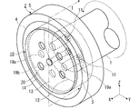
- FIG. 1 is a cross-sectional view illustrating an embodiment of a soundproof cover, showing a state in which a fixed through-hole is closed by a movable cover.
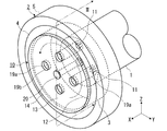
- FIG. 2 is a cross-sectional view illustrating an embodiment of the soundproof cover, and illustrates a state where a fixed through hole is opened.
- FIG. 3 is a perspective view of the soundproof cover in the state of FIG.
- FIG. 4 is a perspective view of the soundproof cover in the state of FIG.
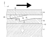
- FIG. 5 is a sectional view indicated by an arrow V in FIG.
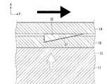
- FIG. 6 is a cross-sectional view indicated by an arrow VI in FIG.
- the X direction is defined as the axial direction of the rotating shaft 1
- the Y direction is defined as a horizontal direction orthogonal to the X direction
- the Z direction is defined as a vertical direction orthogonal to the X direction and the Y direction.
- the front end is the front end of the rotary shaft 1
- the front end side is the front end side of the rotary shaft 1 and is expressed as the outside in the X direction
- the end is the end of the rotary shaft 1 (not shown)
- the end side is the rotary end. It is expressed as the end side of the shaft 1 and inside in the X direction.
- the soundproof cover 10 of the embodiment illustrated in FIGS. 1 to 6 is a soundproof cover of the pulley 2 fixed to the shaft tip of the crankshaft of the engine, which is the rotating shaft 1.
- the rotating shaft 1 is a shaft whose end side (not shown) converts a reciprocating motion of a piston generated by a combustion pressure in a cylinder of the engine into a rotating motion. At the time of the conversion, vibrations of the piston, the connecting rod, and the rotating shaft 1 are excited. Resonant torsionally.
- the pulley 2 includes a shaft body 3 fixed to the shaft tip of the rotating shaft 1, a damper mechanism 4 arranged radially outside the shaft body 3, and a cable ring 5 arranged radially outside the damper mechanism 4.
- the shaft body 3 has a bottomed cylindrical shape with an opening on the outside in the X direction, is made of a metal material, and the inside of the bottom surface in the X direction that is wider than the shaft tip of the rotating shaft 1 in the X direction rotates as a coupling surface. It is fastened to the tip of the shaft 1.
- the damper mechanism 4 has an annular shape when viewed from the X direction, is made of rubber, and is joined to the outer cylinder surface of the shaft body 3.
- the cable ring 5 forms an annular shape when viewed from the X direction, and has a radially inner peripheral surface joined to an outer cylindrical surface of the damper mechanism 4 and a radially outer peripheral surface formed by a looped endless belt or chain (not shown). Contact.
- the pulley 2 has a function of attenuating torsional resonance generated in the rotating shaft 1 by forming an additional spring mass system on the outer periphery by the damper mechanism 4, and a function of transferring power from the rotating shaft 1 to the endless belt or chain by the rope 5. Transmission function.
- the soundproof cover 10 is fastened and fixed to the shaft 3 of the pulley 2 by the fastener 11. That is, the soundproof gabber 10 is indirectly connected to the rotating shaft 1 via the shaft 3 of the pulley 2 by the fastener 11.
- the cover is fastened and fixed. In other words, the soundproof cover 10 is fastened together with the pulley 2 to the rotating shaft 1 by the fastener 11.
- the soundproof cover 10 includes a fixing plate 12, a fixed cover 13, and a movable cover 14 that are sequentially arranged from the bottom surface of the shaft 3 of the pulley 2 toward the outside in the X direction.
- the soundproof cover 10 includes a support mechanism 20 that movably supports the movable cover 14 with respect to the fixing plate 12 and the fixed cover, and a fixing mechanism 30 that inhibits the movement of the movable cover 14 and fixes the position of the movable cover 14.
- the fastener 11 is composed of a bolt having a shaft 11a and a head 11b.
- the shaft portion 11a is a male screw, is inserted through the fixing plate 12 and the shaft body 3 of the pulley 2, and is screwed into a female screw formed at the shaft tip of the rotary shaft 1. That is, the pulley 2 and the soundproof cover 10 are simultaneously fastened to the rotating shaft 1 by the shared fastener 11.
- sharing the fastener 11 is advantageous for reducing the weight.
- the fixing plate 12 has a disk shape substantially the same as the bottom surface of the shaft body 3 when viewed in the X direction, is made of a metal material, and has a plurality of plate through holes 15 and support holes 16a. .
- the fixing plate 12 only needs to have a size capable of forming the plurality of plate through holes 15 and may be smaller than the bottom surface of the shaft body 3. Since both the shaft 3 and the fixing plate 12 are made of a metal material, the bottom surface of the shaft 3 and the end of the fixing plate 12 have a metal touch, and the connection between the shaft 3 and the fixing plate 12 is maintained. To be advantageous. It is also advantageous to maintain the connection and to avoid loosening of the fixing plate 12 during operation of the engine.
- the plurality of plate through holes 15 are arranged at equal intervals in the circumferential direction when viewed in the X direction, penetrate the fixing plate 12 in the X direction, and have a hole diameter such that the head 11b of the fastener 11 cannot be inserted. Further, the shaft portion 11a is configured to have a size that can be inserted.
- a female screw similar to the female screw formed at the shaft tip of the rotary shaft 1 may be formed on the inner surface of the plate through hole 15.
- the supporting hole 16a is arranged at the center of the fixing plate 12 when viewed in the X direction, and penetrates the fixing plate 12 in the X direction.
- the supporting hole 16a has two holes: a hole through which a support shaft 21 of the support mechanism 20 to be described later can be inserted and the retaining portion 22 of the support mechanism 20 cannot be inserted; and a hole through which the retaining portion 22 of the support mechanism 20 can be stored.
- the two holes are arranged in order from the inside in the X direction to the outside.
- the fixed cover 13 has a cylindrical shape in a perspective view, has a sound absorbing material 17, a fixed sound insulating material 18, a plurality of fixed through holes 19 a, and support holes 16 b, and is a fixed cover joined to the fixed plate 12. It is.
- two layers of the layer of the sound absorbing material 17 and the layer of the fixed sound insulating material 18 are integrally joined, and the end of the sound absorbing material 17 is joined to the tip of the fixing plate 12.
- the joining in the fixed cover 13 is exemplified by joining by an adhesive or welding or joining by another fastener different from the fastener 11.
- the sound absorbing material 17 and the fixed sound insulating material 18 preferably have a shape that covers at least a region of the bottom surface of the shaft 3 that is in contact with the shaft tip of the rotating shaft 1 when viewed in the X direction, and covers substantially the entire bottom surface of the shaft 3. Shape is more preferred. Since the sound absorbing material 17 and the fixed sound insulating material 18 cover substantially the entire bottom surface of the shaft 3, it is advantageous to reduce noise radiated through the shaft 3.
- the thickness of the sound absorbing material 17 and the fixed sound insulating material 18 in the X direction is preferably a thickness that substantially fills the space existing inside the bottomed cylindrical shaft body 3. It is more preferable that the height is substantially equal to (the opening edge on the tip side).
- the fixing mechanism 30 is in a state in which a small gap exists between the fixed cover 13 and the moving cover 14. In this state, the sound absorbing material 17 and the fixed sound insulating material 18 are combined in the X direction. It is expressed that the thickness is substantially equal to the height up to the tip of the shaft 3. It is preferable that the thickness of the sound absorbing material 17 in the X direction is larger than the thickness of the fixed sound insulating material 18 in the X direction.
- the sound absorbing material 17 is arranged inside the fixing cover 13 in the X direction, and the end is joined to the front end of the fixing plate 12.
- Examples of the sound absorbing material 17 include a porous or fibrous material in which a large number of fibers are superposed and convert sound energy into heat energy and absorb the heat energy. Examples thereof include urethane, foamed urethane, foamed rubber, and nonwoven fabric of chemical fiber. Is done.
- the fixed sound insulating material 18 is arranged on the outer side in the X direction in the fixed cover 13, the end is joined to the tip of the sound absorbing material 17, and the end is arranged at substantially the same position as the tip of the shaft 3 in the X direction.
- Examples of the fixed sound insulating material 18 include a material made of a dense material that blocks sound by a shielding property to prevent the sound from leaking from the front end of the fixed cover 13 to the front end side in the X direction.
- the fixed sound insulating material 18 has a single-layer structure made of a metal material, rubber, and a synthetic resin, for example. It is preferable that the metal material has a two-layer structure with a synthetic resin that suppresses minute vibration of the metal material.
- the plurality of fixing through holes 19a are arranged at regular intervals in the circumferential direction when viewed in the X direction, penetrate the fixing cover 13 in the X direction, and have a hole diameter through which the shaft portion 11a and the head portion 11b of the fastener 11 are inserted. Configured to the size possible. That is, the hole diameter of the fixed through hole 19a is larger than the hole diameter of the plate through hole 15.
- the support hole 16b is disposed at the center of the sound absorbing material 17 and the fixed sound insulating material 18 when viewed in the X direction, penetrates them in the X direction, and has a hole diameter through which a support shaft 21 of a support mechanism 20 described later can be inserted. , So that the retaining portion 22 cannot be inserted.
- the moving cover 14 has a disk shape in a perspective view, and has a plurality of moving through holes 19b and support holes 16c.
- the movable cover 14 is a movable cover that is movably supported by the support mechanism 20 with respect to the fixing plate 12 and the fixed cover 13 and that is fixed by the fixing mechanism 30.
- the movable cover 14 is disposed such that the distal end can contact the tip of the shaft body 3 (opening edge on the outside in the X direction).
- the movable cover 14 preferably has a shape that covers at least the fixed cover 13 when viewed in the X direction, and has a shape that covers the shaft 3, and more preferably a shape that covers the opening of the shaft 3 as a lid of the bottomed cylindrical shaft 3. preferable.
- the movable cover 14 is exemplified by the same one as the fixed sound insulating material 18, but it is preferably composed of a plurality of layers, and at least one of the plurality of layers is preferably composed of a metal material. Since the side surface of the movable cover 14 is not covered with the shaft body 3 as in the case of the fixed sound insulating material 18, it is desirable to increase the hardness by having a layer made of a metal material.
- the plurality of moving through holes 19b are arranged at equal intervals in the circumferential direction when viewed in the X direction, penetrate the moving cover 14 in the X direction, and are large enough to allow the shaft portion 11a and the head 11b of the fastener 11 to be inserted. It is configured to. That is, the hole diameter of the moving through hole 19b is equal to the hole diameter of the fixed through hole 19a, and is larger than the hole diameter of the plate through hole 15.
- the support hole 16c is arranged at the center of the moving cover 14 when viewed in the X direction, penetrates the moving cover 14 in the X direction, and has a size that allows a support shaft 21 of a support mechanism 20, which will be described later, to be inserted. You.
- the support mechanism 20 includes a support shaft 21 whose axial direction is oriented in the X direction, and retaining portions 22 arranged at both ends of the support shaft 21 in the X direction.
- the support shaft 21 is inserted into each of the support holes 16a of the fixing plate 12, the support holes 16b of the fixed cover 13, and the support holes 16c of the movable cover 14.
- the retaining portion 22 functions so that the support shaft 21 does not come out of the support holes 16a to 16c.
- the support mechanism 20 is a mechanism that rotates the movable cover 14 about the support shaft 21 while supporting the movable cover 14.
- the support shaft 21 may be arranged at a position other than the center of the movable cover 14 when viewed in the X direction.
- the support shaft 21 may be arranged at the center of the movable cover 14 when viewed in the X direction. desirable.
- the movable cover 14 can be rotatably supported in the circumferential direction of the rotating shaft 1 with respect to the fixing plate 12 and the fixed cover 13, which is advantageous for avoiding unnecessary protrusion when the movable cover 14 is moved. become.
- the fixing mechanism 30 has a plurality of pairs of concave portions 31 and convex portions 32, and these concave portions 31 and convex portions 32 Are also arranged radially outward of the rotating shaft 1 and at equal intervals in the circumferential direction when viewed in the X direction.
- the fixing mechanism 30 sets the movable cover 14 in a movable state until the concave portion 31 and the convex portion 32 are fitted, and prohibits the movement of the movable cover 14 when the convex portion 32 is fitted into the concave portion 31. This is a mechanism for fixing the position of the moving cover 14.
- the recess 31 is formed by recessing the tip of the fixed cover 13 inward in the X direction (downward in the figure).
- the projection 32 is formed by projecting the end of the moving cover 14 inward in the X direction.
- the cross-sectional shape of the depression of the concave portion 31 is formed substantially the same as the cross-sectional shape of the protrusion of the convex portion 32.
- Each of the concave portion 31 and the convex portion 32 has a shape having at least two surfaces of opposing surfaces 33 and 34 and inclined surfaces 35 and 36 when viewed in a radial direction (for example, the Y direction) of the rotating shaft 1.
- the opposing surfaces 33 and 34 are surfaces whose vertical direction faces the circumferential direction of the rotating shaft 1 when viewed in the radial direction of the rotating shaft 1, and are opposed to each other when the concave portion 31 and the convex portion 32 are fitted to each other. It is a side to
- the facing surface 33 is a surface whose vertical direction faces the rotation direction of the rotating shaft 1 in the circumferential direction
- the facing surface 34 is a surface whose vertical direction faces the direction opposite to the rotation direction of the rotation shaft.
- the inclined surfaces 35 and 36 are surfaces inclined with respect to the end surfaces of the fixed cover 13 and the movable cover 14.
- the inclined surface 35 is an inclined surface whose end on the rotation direction side is disposed outside in the X direction from the end on the opposite side in the rotation direction, and the inclined surface 36 has an end on the rotation direction side opposite to the rotation direction.
- the inclined surfaces are disposed on the outer side in the X direction from the portions, and are the inclined surfaces that guide the convex portions 32 fitted into the concave portions 31 to the outside of the concave portions 31 when the movable cover 14 is rotated in the rotation direction of the rotating shaft 1. .
- the inclined surfaces 35 and 36 reduce the rotation speed and cause the moving cover 14 to have an inertia moment in the opposite direction to the rotation direction. Even if it acts, the fitting state can be maintained by the frictional force between the inclined surfaces 35 and 36.
- the angles and areas of the inclined surfaces 35 and 36 are such that the fitting of the concave portion 31 and the convex portion 32 cannot be released due to a change in the rotation speed of the rotating shaft 1, and that the concave portion 31 and the convex portion The angle and the area where the fitting of 32 is released are set.
- the fixing mechanism 30 inhibits the movement of the movable cover 14 when the movable cover 14 is rotated in the rotation direction of the rotating shaft 1 with respect to the fixed cover 13, and releases the inhibition of the movement of the movable cover 14.
- This is a configuration for switching between the state and the state to be performed.
- the fixing mechanism 30 is configured to permit the rotational movement of the movable cover 14 in the rotational direction of the rotary shaft 1 and restrict the rotational movement of the movable cover 14 in the direction opposite to the rotational direction of the rotary shaft 1. .
- the operator rotates the movable cover 14 in which the engagement between the concave portion 31 and the convex portion 32 is released and the prohibition of the movement by the fixing mechanism 30 is released in the rotation direction of the rotary shaft 1 about the support shaft 21.
- the fixed through hole 19a of the fixed cover 13 and the moving through hole 19b of the moving cover 14 are overlapped in the X direction.
- the fixed through hole 19a and the moving through hole 19b become one through hole, and the fixed through hole 19a is open to the outside.
- the worker loosens or tightens the fastening by the fastener 11 to attach and detach the fixing plate 12 to and from the pulley 2. Will be possible.
- the portion of the movable cover 14, which is prohibited from being moved by the fixing mechanism 30, where the moving through-hole 19 b is not formed (the portion between the moving through-holes 19 b adjacent to each other in the circumferential direction of the rotating shaft 1) is used as the fixed cover 13.
- the fixed through hole 19a is closed.
- the fastener 11 is transmitted from the rotary shaft 1 and noise radiated from the fastener 11 is transmitted to the moving cover 14. This makes it possible to provide sound insulation.
- the fixing plate 12 is fastened to the rotating shaft 1 and the pulley 2 by using the fastener 11, so that the rotating shaft 1 and the pulley 2 While being detachable, the rotation shaft 1 and the pulley 2 are prevented from falling off during rotation. Further, by closing the fixed through-hole 19a into which the fastener 11 is inserted by the moving cover 14, the fastener 11 is transmitted from the rotating shaft 1 and the pulley 2, and the noise radiated from the fastener 11 can be reduced. it can.
- the soundproof cover 10 of the present disclosure is composed of at least three layers, and each of the three layers has a different function.
- the first layer of the soundproof cover 10 is a fixing plate 12 for preventing falling off during rotation
- the second layer is for preventing noise radiated from the rotating shaft 1 or the shaft 3 of the pulley 2.
- the third layer is a movable cover 14 for preventing noise radiated from the fastener 11.
- the soundproof cover 10 can be attached to the rotating shaft 1 with the fasteners 11 together with the work of attaching the pulley 2 to each layer by integrally forming the layers, which is advantageous for shortening the time required for the attachment work. Become.
- the movable cover 14 closes the shaft 3 of the pulley 2.
- the rotating shaft 1 is exemplified as the crankshaft of the engine.
- the present invention is applicable to any shaft that emits noise from the shaft tip.
- the rotating shaft 1 may be used as the drive shaft of the motor generator. Is also good.
- the soundproof cover 10 is exemplified as a cover that is indirectly fastened to the rotating shaft 1 via the shaft body 3 of the pulley 2 by the fastener 11, but the soundproof cover 10 is fastened by the fastener 11.
- the cover may be directly fastened to the rotating shaft 1.
- the soundproof cover 10 includes a fixing plate 12, a fixed cover 13, and a movable cover 14 arranged in order from the tip of the rotation shaft 1 toward the outside in the X direction. Further, the fixed cover 13 and the movable cover 14 may have a shape that covers the tip of the rotating shaft 1.
- the soundproof cover 10 of the present disclosure is also applicable to a case in which the shaft 3 of the pulley 2 has a cylindrical shape, and the inner peripheral surface thereof is fastened to the outer peripheral surface of the shaft end of the rotating shaft 1 as a coupling surface. It is.
- the fixing plate 12 may have a bottomed cylindrical shape in the same shape as the shaft body 3, and an outer cylindrical surface other than the end may be in contact with the inner cylindrical surface of the shaft body 3.
- the plate through-hole 15 and the fixed through-hole 19a may be filled with a plug made of the sound absorbing material 17 or the fixed sound insulating material 18, and then closed with the moving cover 14. Since this stopper is pressed by a portion of the movable cover 14 where the movable through-hole 19b is not formed, even if the rotating shaft 1 rotates, the stopper is prevented from protruding outward in the X direction.
- a plurality of the moving covers 14 described above may be stacked. By using a plurality of moving covers 14 and closing the moving through holes 19b formed respectively, it is advantageous to further improve sound insulation.
- the support mechanism 20 may be any mechanism that rotates the movable cover 14 about the support shaft 21 and is not limited to the above configuration.
- one end of the support shaft 21 may be screwed to the fixing plate 12.
- the fixing mechanism 30 only needs to be able to prohibit the movement of the moving cover 14, and may be constituted by at least one set of the concave portion 31 and the convex portion 32.
- the fixing mechanism 30 is radially inward of the rotating shaft 1 from the fixed through hole 19 a and the moving through hole 19 b. May be arranged.
- the concave portion 31 may be arranged on the movable cover 14 and the convex portion 32 may be arranged on the fixed cover 13.
- the recess 31 may be provided at the tip of the protrusion protruding outward in the X direction from the tip of the fixed cover 13 as long as the protrusion 32 is configured to be fittable.
- one of the concave portion 31 and the convex portion 32 may be provided on the support shaft 21, and the other may be provided on the inner peripheral surface of the support hole 16 c of the movable cover 14.
- the fixing mechanism 30 is configured such that when the inclined surface 36 of the convex portion 32 is urged toward the concave portion 31 by elastic force, and the concave portion 31 and the convex portion 32 are disengaged, the inclined surface 36 is retracted, When the concave portion 31 and the convex portion 32 are fitted, the inclined surface 36 may protrude.
- the present invention has an effect of avoiding falling off during rotation and reducing noise, and is useful for a soundproof cover or the like.
Landscapes
- Engineering & Computer Science (AREA)
- General Engineering & Computer Science (AREA)
- Physics & Mathematics (AREA)
- Acoustics & Sound (AREA)
- Mechanical Engineering (AREA)
- Chemical & Material Sciences (AREA)
- Combustion & Propulsion (AREA)
- Pulleys (AREA)
- Vehicle Interior And Exterior Ornaments, Soundproofing, And Insulation (AREA)
Abstract
防音カバー10は、固定用プレート12、固定カバー13、移動カバー14、支持機構20、及び固定機構30を備え、固定用プレート12が締結具11により着脱自在に固定され、固定カバー13が固定用プレート12に接合されると共に締結具11が挿通可能な固定貫通孔19aが形成され、移動カバー14が固定カバー13を覆う形状を成し、固定用プレート12を着脱する場合に固定機構30による移動の禁止が解除された移動カバー14を移動させて固定貫通孔19aを空けた状態にし、それ以外の場合に固定機構30により移動が禁止された移動カバー14により固定貫通孔19aを塞いだ状態にする。
Description
本開示は、防音カバーに関し、より詳細には、回転軸あるいは回転軸の端部に取り付けられたプーリーから放射される騒音を低減する防音カバーに関する。
回転軸の端部やプーリーから放射される騒音を低減する防音カバーが提案されている(例えば、特許文献1、2、3を参照)。
特許文献1に記載のカバーは、プーリーに対してボルトなどの締結具を用いて固定されているため、エンジンの実働運転時に脱落するおそれが無い一方で、締結具を伝達して騒音が放射されるため、騒音を低減する効果が半減してしまう。
しかし、特許文献2、3に記載のカバーのように、プーリーに対して締結具を用いずに固定されると、容易に着脱可能になる一方で、エンジンの実働運転時に脱落するおそれがある。
このように、防音カバーは、回転軸やプーリーに対して締結具を用いて固定されることが望ましいが、その締結具からの騒音の放射を低減する必要があった。
本開示の目的は、回転時の脱落を回避すると共に騒音を低減することができる防音カバーを提供することである。
上記の目的を達成する本発明の一態様の防音カバーは、回転軸の軸先端から軸方向外側に向かって順に配置される固定用プレート、固定カバー、及び移動カバーと、前記移動カバーを前記固定用プレート及び前記固定カバーに対して移動自在に支持する支持機構と、前記移動カバーの移動を禁止して前記移動カバーの位置を固定する固定機構と、を備え、前記固定用プレートは、前記固定用プレート及び前記回転軸に挿通される軸部と前記固定用プレートから軸方向外側に向かって突出する頭部を有する締結具により前記軸先端に着脱自在に固定され、前記固定カバーは、前記軸先端を覆う形状を成し、前記固定用プレートに接合されると共に前記締結具の前記頭部が挿通可能な固定貫通孔が形成され、前記移動カバーは、前記固定カバーを覆う形状を成し、前記固定用プレートを着脱する場合に前記固定機構による移動の禁止が解除された前記移動カバーを移動させて前記固定貫通孔を空けた状態にし、それ以外の場合に前記固定機構により移動が禁止された前記移動カバーにより前記固定貫通孔を塞いだ状態にすることを特徴とする。
上記の目的を達成する本発明の一態様の防音カバーは、プーリーの防音カバーにおいて、前記プーリーは、回転軸の軸先端部に固定される軸体と、前記軸体の径方向外側に配置される索輪と、を有し、前記軸体から前記回転軸の軸方向外側に向かって順に配置される固定用プレート、固定カバー、及び移動カバーと、前記移動カバーを前記固定用プレート及び前記固定カバーに対して移動自在に支持する支持機構と、前記移動カバーの移動を禁止して前記移動カバーの位置を固定する固定機構とを備え、前記固定用プレートは、前記固定用プレート及び前記軸体に挿通される軸部とこの固定用プレートから軸方向外側に向かって突出する頭部を有する締結具により前記軸体に着脱自在に固定され、前記固定カバーは、前記軸体のうちの前記回転軸の軸先端に接する領域を少なくとも覆う形状を成し、前記固定用プレートに接合されると共に前記締結具の前記頭部が挿通可能な固定貫通孔が形成され、前記移動カバーは、前記固定カバーを覆う形状を成し、前記固定用プレートを着脱する場合に前記固定機構による移動の禁止が解除された前記移動カバーを移動させて前記固定貫通孔を空けた状態にし、それ以外の場合に前記固定機構により移動が禁止された前記移動カバーにより前記固定貫通孔を塞いだ状態にすることを特徴とする。
本発明の一態様によれば、回転時の脱落を回避すると共に騒音を低減することができる。
以下に、防音カバーの実施形態について説明する。図中では、X方向を回転軸1の軸方向とし、Y方向をX方向に直交する水平方向とし、Z方向をX方向及びY方向に直交する鉛直方向とする。本明細書において、先端は回転軸1の先端であり、先端側は回転軸1の先端側であってX方向外側と表現し、末端は図示しない回転軸1の末端であり、末端側は回転軸1の末端側であってX方向内側と表現する。
図1~図6に例示する実施形態の防音カバー10は、回転軸1であるエンジンのクランク軸の軸先端部に固定されるプーリー2の防音カバーである。
回転軸1は、図示しない末端側がエンジンのシリンダ内の燃焼圧力によって生じるピストンの往復運動を回転運動に変換するシャフトであり、変換の際にピストン、コンロッド、及び回転軸1の振動が励起されてねじり共振する。
プーリー2は、回転軸1の軸先端部に固定される軸体3と軸体3の径方向外側に配置されるダンパー機構4とダンパー機構4の径方向外側に配置される索輪5とを有する。軸体3は、X方向外側が開口した有底筒状を成し、金属材料で構成されて、X方向に見て回転軸1の軸先端よりも広い底面のX方向内側が結合面として回転軸1の軸先端に締結される。ダンパー機構4は、X方向から見て環状を成し、ゴムで構成されて、軸体3の外筒面に接合される。索輪5は、X方向から見て環状を成し、径方向内周面がダンパー機構4の外筒面に接合され、径方向外周面が図示しない掛け回された無端状のベルト又はチェーンに接触する。
プーリー2は、ダンパー機構4により外周に付加バネマス系が形成されることで、回転軸1に生じるねじり共振を減衰させる機能と、索輪5により回転軸1から無端状のベルト又はチェーンに動力を伝達する機能とを有する。
防音カバー10は、締結具11によりプーリー2の軸体3に締結されて固定される、つまり、防音ガバー10は、締結具11によりプーリー2の軸体3を介して間接的に回転軸1に締結されて固定されるカバーである。換言すると、防音カバー10は、締結具11により回転軸1にプーリー2と共に共締めされる。
防音カバー10は、プーリー2の軸体3の底面からX方向外側に向かって順に配置される固定用プレート12、固定カバー13、及び移動カバー14を備える。また、防音カバー10は、移動カバー14を固定用プレート12及び固定カバーに対して移動自在に支持する支持機構20と移動カバー14の移動を禁止して移動カバー14の位置を固定する固定機構30とを備える。
締結具11は、軸部11aと頭部11bとを有するボルトで構成される。軸部11aは、雄ねじであり、固定用プレート12及びプーリー2の軸体3に挿通されて、回転軸1の軸先端部に形成される雌ねじに捩じ込まれる。つまり、プーリー2及び防音カバー10は、共有の締結具11により回転軸1に対して同時に締結される。このように、プーリー2の取付作業と防音カバー10の取付作業とを同時に行うことで、製造に要する時間を短縮するには有利になる。また、締結具11を共有にすることで、軽量化を図るには有利になる。
固定用プレート12は、X方向に見て軸体3の底面と略同形状の円盤形状を成し、金属材料で構成され、複数のプレート用貫通孔15と支持用孔16aとが形成される。
固定用プレート12は、複数のプレート用貫通孔15が形成可能な大きさであればよく、軸体3の底面よりも小さくてもよい。軸体3及び固定用プレート12の両方が金属材料で構成されることで、軸体3の底面と固定用プレート12の末端とがメタルタッチとなり、軸体3及び固定用プレート12の結合を維持するには有利になる。また、その結合を維持するには有利になり、エンジンの稼働中の固定用プレート12の緩みを回避するにも有利になる。
複数のプレート用貫通孔15は、X方向に見て周方向に等間隔に配置されて固定用プレート12をX方向に貫通し、その孔径が締結具11の頭部11bが挿通不可能で、且つ軸部11aが挿通可能な大きさに構成される。このプレート用貫通孔15の内表面に回転軸1の軸先端部に形成される雌ねじと同様の雌ねじを形成してもよい。
支持用孔16aは、X方向に見て固定用プレート12の中央部に配置されて、固定用プレート12をX方向に貫通する。支持用孔16aは、後述する支持機構20の支持軸21が挿通可能で且つ支持機構20の抜止部22が挿通不可能な孔と、支持機構20の抜止部22を収納可能な孔との二つの孔がX方向内側から外側に向かって順に配置される。
固定カバー13は、斜視図において円柱形状を成し、吸音材17と固定遮音材18と複数の固定貫通孔19aと支持用孔16bを有し、固定用プレート12に接合される固定式のカバーである。固定カバー13は、吸音材17の層と固定遮音材18の層との二層が一体的に接合されると共に、吸音材17の末端が固定用プレート12の先端に接合される。固定カバー13における接合は、接着剤や溶着による接合や締結具11とは異なる別の締結具による接合が例示される。
吸音材17及び固定遮音材18は、X方向に見て、軸体3の底面のうちの回転軸1の軸先端に接する領域を少なくとも覆う形状が好ましく、軸体3の底面の略全域を覆う形状がより好ましい。吸音材17及び固定遮音材18が軸体3の底面の略全域を覆うことで、軸体3を介して放射される騒音を低減するには有利になる。吸音材17及び固定遮音材18を合わせたX方向の厚さは、有底筒状の軸体3の内部に存在する空間を略埋める厚さが好ましく、固定用プレート12から軸体3の先端(先端側の開口縁)までの高さと略等しいことがより好ましい。なお、本実施形態では固定機構30により固定カバー13及び移動カバー14の間に多少の隙間が存在する状態であるが、その状態も含めて吸音材17及び固定遮音材18を合わせたX方向の厚さが軸体3の先端までの高さと略等しいと表現する。また、吸音材17のX方向の厚さを固定遮音材18のX方向の厚さよりも厚くすることが好ましい。このように吸音材17及び固定遮音材18によりプーリー2の軸体3の内部に存在する空間を埋めることで、回転軸1の軸先端から軸体3を介して放射される騒音を吸音材17で吸収すると共に、固定遮音材18で遮音することができる。
吸音材17は、固定カバー13においてX方向内側に配置されて、末端が固定用プレート12の先端に接合される。吸音材17としては、多孔質あるいは多数の繊維が重なった繊維状の材料で音エネルギーを熱エネルギーに変換して吸収するものが例示され、ウレタン、発泡ウレタン、発泡ゴム、及び化学繊維不織布が例示される。
固定遮音材18は、固定カバー13においてX方向外側に配置されて、末端が吸音材17の先端に接合され、X方向において末端が軸体3の先端と略同じ位置に配置される。固定遮音材18としては、緻密の材料で遮蔽性により音を遮断して固定カバー13の先端からX方向先端側に漏れ出ることを防ぐものが例示される。固定遮音材18としては、金属材料、ゴム、及び合成樹脂で構成される単層構造のものが例示されるが、末端側に配置される単位体積当たりの重量が大きい金属材料と先端側に配置されるその金属材料の微小な振動を抑制する合成樹脂との二層構造のものが好ましい。
複数の固定貫通孔19aは、X方向に見て周方向に等間隔に配置されて固定カバー13をX方向に貫通し、その孔径が締結具11の軸部11a及び頭部11bのそれぞれが挿通可能な大きさに構成される。つまり、固定貫通孔19aの孔径は、プレート用貫通孔15の孔径よりも大きい。
支持用孔16bは、X方向に見て吸音材17及び固定遮音材18の中央部に配置されて、それらをX方向に貫通し、その孔径が後述する支持機構20の支持軸21が挿通可能で抜止部22が挿通不可能な大きさに構成される。
移動カバー14は、斜視図において円盤形状を成し、複数の移動貫通孔19bと支持用孔16cとを有する。移動カバー14は、支持機構20により固定用プレート12及び固定カバー13に対して移動自在に支持されると共に、固定機構30により移動を固定される移動式のカバーである。
移動カバー14は、末端が軸体3の先端(X方向外側の開口縁)に接触可能に配置される。移動カバー14は、X方向に見て、固定カバー13を少なくとも覆う形状が好ましく、軸体3を覆う形状で、有底筒状の軸体3の蓋として軸体3の開口を塞ぐ形状がより好ましい。移動カバー14により軸体3の開口を塞ぐことで、軸体3から放射される騒音の遮音性を高めることができる。移動カバー14としては、固定遮音材18と同様のものが例示されるが、複数の層で構成されて、その複数の層のうちの少なくとも一層が金属材料で構成されることが好ましい。移動カバー14は側面が固定遮音材18のように軸体3により覆われていないことから、金属材料で構成された層を有することで、硬度を高めることが望ましい。
複数の移動貫通孔19bは、X方向に見て周方向に等間隔に配置されて移動カバー14をX方向に貫通し、締結具11の軸部11a及び頭部11bのそれぞれが挿通可能な大きさに構成される。つまり、移動貫通孔19bの孔径は、固定貫通孔19aの孔径と等しく、プレート用貫通孔15の孔径よりも大きい。
支持用孔16cは、X方向に見て移動カバー14の中央部に配置されて、移動カバー14をX方向に貫通し、後述する支持機構20の支持軸21が挿通可能な大きさに構成される。
支持機構20は、X方向に軸方向が向いてなる支持軸21と支持軸21のX方向両端部に配置される抜止部22を有する。支持軸21は、固定用プレート12の支持用孔16a、固定カバー13の支持用孔16b、及び移動カバー14の支持用孔16cのそれぞれに挿通される。抜止部22は、各支持用孔16a~16cから支持軸21が抜けないように機能する。
支持機構20は、移動カバー14を支持しつつ、支持軸21を中心として移動カバー14を回転移動させる機構である。支持機構20は、X方向に見て支持軸21が移動カバー14の中央部以外に配置されてもよいが、X方向に見て支持軸21が移動カバー14の中央部に配置されることが望ましい。支持軸21が中央部に配置されることで、回転軸1の回転時に防音カバー10の偏心を回避するには有利になる。また、移動カバー14を固定用プレート12及び固定カバー13に対して回転軸1の周方向に回転自在に支持可能になり、移動カバー14を移動させた場合の不要なはみ出しを回避するには有利になる。
図5及び図6に例示するように、固定機構30は、対となる凹部31及び凸部32を複数有し、それらの凹部31及び凸部32が、固定貫通孔19a及び移動貫通孔19bよりも回転軸1の径方向外側で、X方向に見て周方向に等間隔に配置されて成る。固定機構30は、凹部31及び凸部32が嵌合するまでの間で移動カバー14を移動可能な状態にし、凸部32が凹部31に嵌合したときに移動カバー14の移動を禁止して移動カバー14の位置を固定する機構である。
凹部31は、固定カバー13の先端をX方向内側(図中下方)に向かって窪ませて成る。凸部32は、移動カバー14の末端をX方向内側に向かって突出させて成る。凹部31の窪みの断面形状は、凸部32の突起の断面形状と略同一に形成される。凹部31及び凸部32のそれぞれは、回転軸1の径方向(例えば、Y方向)に見て、対向面33、34と傾斜面35、36との少なくとも二つの面を有する形状を成す。
対向面33、34は、回転軸1の径方向に見て、面垂直方向が回転軸1の周方向に向いた面であり、凹部31及び凸部32どうしが嵌合した状態で互いに対向接触する面である。対向面33は面垂直方向が周方向のうちの回転軸1の回転方向に向いた面であり、対向面34は面垂直方向が回転軸の回転方向の反対側の方向に向いた面である。また、対向面33、34は、凹部31及び凸部32が嵌合した状態で回転軸1が回転する場合に、その回転速度が増加すると、回転軸1の回転に伴って回転する対向面33がその回転方向に対向面34を押すことで、回転軸1の回転により凹部31及び凸部32の嵌合が維持可能に構成される。
傾斜面35、36は、固定カバー13及び移動カバー14の端面に対して傾いた面である。傾斜面35は回転方向側の端部が回転方向の反対側の端部よりもX方向外側に配置された斜面であり、傾斜面36は回転方向側の端部が回転方向の反対側の端部よりもX方向外側に配置された斜面であり、それぞれ移動カバー14を回転軸1の回転方向に回したときに凹部31に嵌合された凸部32を凹部31の外に導く斜面である。また、傾斜面35、36は、凹部31及び凸部32が嵌合した状態で回転軸1が回転する場合に、その回転速度が減速して移動カバー14に回転方向と反対方向の慣性モーメントが作用しても、傾斜面35、36どうしの間の摩擦力で嵌合状態を維持可能に構成される。
傾斜面35、36の角度や面積は、回転軸1の回転速度の変化で凹部31及び凸部32の嵌合が解かれない、且つ作業者による移動カバー14の回転移動で凹部31及び凸部32の嵌合が解かれる角度や面積に設定される。
この固定機構30は、移動カバー14を固定カバー13に対して回転軸1の回転方向に回転移動させたときに、移動カバー14の移動を禁止する状態と、移動カバー14の移動の禁止を解除する状態とを切り替える構成である。換言すると、固定機構30は、回転軸1の回転方向への移動カバー14の回転移動を許可し、回転軸1の回転方向の反対の方向への移動カバー14の回転移動を制限する構成である。
図3に例示する状態から図4に例示する状態にする方法を説明する。作業者は、移動カバー14を回転軸1の回転方向に回転させる力を移動カバー14に付与する。移動カバー14に付与されたその力が傾斜面35、36どうしの間の摩擦力よりも大きくなったときに、対向面33、34どうしが周方向に離間すると共に、傾斜面35、36どうしが互いに乗り上げて、固定カバー13の吸音材17がX方向に縮んだ状態になり、凹部31と凸部32の嵌合が解かれる。次いで、作業者は、凹部31と凸部32の嵌合が解かれて固定機構30による移動の禁止が解除された移動カバー14を、支持軸21を軸として回転軸1の回転方向に回転移動させて、固定カバー13の固定貫通孔19aと移動カバー14の移動貫通孔19bとをX方向に重ねる。このとき、固定貫通孔19a及び移動貫通孔19bが一つの貫通孔となり、固定貫通孔19aが外部に対して空いた状態になる。このように、固定貫通孔19aが外部に対して空いた状態になると、作業者が、締結具11による締結を弛めたり又は締めたりして、固定用プレート12をプーリー2に着脱することが可能になる。
図4に例示する状態から図3に例示する状態にする方法を説明する。作業者は、移動カバー14を回転軸1の回転方向に回転移動させる。次いで、移動カバー14の回転移動により、凹部31と凸部32との位置を合わせて、凹部31と凸部32とを嵌合させる。凹部31と凸部32とが嵌合すると、対向面33、34どうしが対向接触すると共に、傾斜面35、36どうしも対向接触する。このとき、固定機構30により移動が禁止された移動カバー14の移動貫通孔19bが形成されていない部位(回転軸1の周方向に隣り合う移動貫通孔19bどうしの間の部位)により固定カバー13の固定貫通孔19aが塞がれた状態になる。このように、固定貫通孔19aが塞がれた状態になると、回転軸1が回転した場合に、回転軸1から締結具11を伝達してその締結具11から放射される騒音を移動カバー14により遮音することが可能になる。
以上のように、本開示の防音カバー10によれば、締結具11を用いて固定用プレート12を回転軸1及びプーリー2に対して締結する構成にしたことで、回転軸1及びプーリー2に対して着脱自在でありながら、回転軸1及びプーリー2の回転時の脱落が防止される。また、締結具11が挿通された固定貫通孔19aを移動カバー14により塞ぐことで、回転軸1及びプーリー2から締結具11を伝達してその締結具11から放射される騒音を低減することができる。
つまり、本開示の防音カバー10は少なくとも三層で構成され、その三層がそれぞれ異なる機能を有する。具体的に、防音カバー10の一層目は回転時の脱落を防止するための固定用プレート12であり、二層目は回転軸1又はプーリー2の軸体3から放射される騒音を防止するための固定カバー13であり、三層目は締結具11から放射される騒音を防止するための移動カバー14である。このように、防音カバー10を構成する各層を一体的に構成すると共に、各層がそれぞれに異なる機能を有することで、回転時の脱落を回避すると共に騒音を低減することができる。
また、防音カバー10は、各層が一体的に構成されることで、回転軸1にプーリー2を取り付ける作業と共に、締結具11により取り付けることが可能となり、取付作業に要する時間の短縮には有利になる。
本開示の防音カバー10は、移動カバー14がプーリー2の軸体3を塞ぐ。これにより、回転軸1や軸体3への水、ホコリなどのゴミの侵入を防ぐには有利になり、回転軸1やプーリー2への汚れの付着や錆の発生を防止することができる。
既述した実施形態では、回転軸1をエンジンのクランク軸として例示したが、軸先端部から騒音を放射する軸であれば適用可能であり、例えば、回転軸1を電動発電機の駆動軸としてもよい。
また、既述した実施形態では、防音カバー10を締結具11によりプーリー2の軸体3を介して間接的に回転軸1に締結されるカバーとして例示したが、防音カバー10を締結具11により直接的に回転軸1に締結されるカバーとしてもよい。この場合に、防音カバー10は、回転軸1の軸先端からX方向外側に向かって順に固定用プレート12、固定カバー13、及び移動カバー14が配置される。また、固定カバー13及び移動カバー14は、回転軸1の軸先端を覆う形状を成せばよい。つまり、本開示の防音カバー10は、プーリー2の軸体3が筒状を成し、その内周面が結合面として回転軸1の軸端部の外周面に締結されたものにも適用可能である。
固定用プレート12は、軸体3と同形状に有底筒状を成し、末端以外に外筒面が軸体3の内筒面に接触する構成にしてもよい。このように、固定用プレート12と軸体3との接触部位を多くすることで、固定用プレート12の結合を維持するには有利になると共に、固定用プレート12の慣性モーメントを大きくすることができ、回転軸1の質量を低減することもできる。また、固定用プレート12の外筒面が軸体3の内筒面に接触する構成にする場合に、その外筒面と内筒面とを別の締結具により締結してもよい。外筒面と内筒面とを締結具により締結することで、慣性モーメントを大きくすることができる。
締結具11により固定用プレート12を締結した後に、プレート用貫通孔15及び固定貫通孔19aを吸音材17や固定遮音材18で構成された栓で埋めてから、移動カバー14で塞いでもよい。なお、この栓は、移動カバー14の移動貫通孔19bが形成されていない部位により押さえられるので、回転軸1が回転してもX方向外側への飛び出しが防止される。
既述した移動カバー14を複数重ねてもよい。移動カバー14を複数にしてそれぞれに形成された移動貫通孔19bを塞ぐことでより遮音性を向上するには有利になる。
支持機構20は、支持軸21を中心として移動カバー14を回転移動させる機構であればよく、上記の構成に限定されない。例えば、支持軸21の一端部が固定用プレート12に螺合される構成でもよい。
固定機構30は、移動カバー14の移動を禁止できればよく、少なくとも一組の凹部31及び凸部32で構成されてもよく、固定貫通孔19a及び移動貫通孔19bよりも回転軸1の径方向内側に配置されてもよい。また、凹部31を移動カバー14に、凸部32を固定カバー13に配置してもよい。さらに、凹部31は、凸部32が嵌合可能に構成されていればよく、固定カバー13の先端からX方向外側に向かって突出させた突起の先端に設けることもできる。加えて、凹部31及び凸部32の一方を支持軸21に設け、他方を移動カバー14の支持用孔16cの内周面に設けてもよい。
また、固定機構30は、凸部32の傾斜面36が弾性力により凹部31の側に付勢されて、凹部31及び凸部32の嵌合が解かれた場合にその傾斜面36が引っ込み、凹部31及び凸部32が嵌合する場合にその傾斜面36が出っ張る構成にしてもよい。
本出願は、2018年8月27日付で出願された日本国特許出願(特願2018-158194)に基づくものであり、その内容はここに参照として取り込まれる。
本発明は、回転時の脱落を回避すると共に騒音を低減することができるという効果を有し、防音カバー等に有用である。
1 回転軸
2 プーリー
3 軸体
5 索輪
10 防音カバー
11 締結具
12 固定用プレート
13 固定カバー
14 移動カバー
20 支持機構
30 固定機構
2 プーリー
3 軸体
5 索輪
10 防音カバー
11 締結具
12 固定用プレート
13 固定カバー
14 移動カバー
20 支持機構
30 固定機構
Claims (8)
- 回転軸の軸先端から軸方向外側に向かって順に配置される固定用プレート、固定カバー、及び移動カバーと、
前記移動カバーを前記固定用プレート及び前記固定カバーに対して移動自在に支持する支持機構と、
前記移動カバーの移動を禁止して前記移動カバーの位置を固定する固定機構と、を備え、
前記固定用プレートは、前記固定用プレート及び前記回転軸に挿通される軸部と前記固定用プレートから軸方向外側に向かって突出する頭部を有する締結具により前記軸先端に着脱自在に固定され、
前記固定カバーは、前記軸先端を覆う形状を成し、前記固定用プレートに接合されると共に前記締結具の前記頭部が挿通可能な固定貫通孔が形成され、
前記移動カバーは、前記固定カバーを覆う形状を成し、
前記固定用プレートを着脱する場合に前記固定機構による移動の禁止が解除された前記移動カバーを移動させて前記固定貫通孔を空けた状態にし、それ以外の場合に前記固定機構により移動が禁止された前記移動カバーにより前記固定貫通孔を塞いだ状態にすることを特徴とする防音カバー。 - 前記支持機構は、前記回転軸の軸方向に見て前記移動カバーの中央部を軸支する支持軸を有し、前記移動カバーを前記固定用プレート及び前記固定カバーに対して前記回転軸の周方向に回転自在に支持し、
前記移動カバーが、前記締結具の前記頭部が挿通可能な複数の移動貫通孔を有し、
前記固定用プレートを着脱する場合に前記固定機構により移動の禁止が解除された前記移動カバーを前記回転軸の周方向に回転させて前記固定貫通孔と前記移動貫通孔とを前記回転軸の軸方向に重ねて前記固定貫通孔を空けた状態にし、それ以外の場合に前記固定機構により移動が禁止された前記移動カバーの前記移動貫通孔が形成されていない部位により前記固定貫通孔を塞いだ状態にする請求項1に記載の防音カバー。 - 前記固定機構は、前記移動カバーを前記固定カバーに対して前記回転軸の回転方向に回転移動させたときに、前記移動カバーの移動を禁止する状態と、前記移動カバーの移動の禁止を解除する状態とを切り替える構成である請求項2に記載の防音カバー。
- 前記固定機構は、前記固定カバー又は前記移動カバーのどちらか一方に設けられた凹部と他方に設けられた凸部とを有し、前記凹部及び前記凸部が互いに嵌合したときに前記移動カバーの移動を禁止して、前記凹部及び前記凸部の嵌合が解かれたときに前記移動カバーの移動の禁止を解除する構成である請求項3に記載の防音カバー。
- プーリーの防音カバーにおいて、前記プーリーは、回転軸の軸先端部に固定される軸体と、前記軸体の径方向外側に配置される索輪と、を有し、
前記軸体から前記回転軸の軸方向外側に向かって順に配置される固定用プレート、固定カバー、及び移動カバーと、
前記移動カバーを前記固定用プレート及び前記固定カバーに対して移動自在に支持する支持機構と、
前記移動カバーの移動を禁止して前記移動カバーの位置を固定する固定機構と、を備え、
前記固定用プレートは、前記固定用プレート及び前記軸体に挿通される軸部とこの固定用プレートから軸方向外側に向かって突出する頭部を有する締結具により前記軸体に着脱自在に固定され、
前記固定カバーは、前記軸体のうちの前記回転軸の軸先端に接する領域を少なくとも覆う形状を成し、前記固定用プレートに接合されると共に前記締結具の前記頭部が挿通可能な固定貫通孔が形成され、
前記移動カバーは、前記固定カバーを覆う形状を成し、
前記固定用プレートを着脱する場合に前記固定機構による移動の禁止が解除された前記移動カバーを移動させて前記固定貫通孔を空けた状態にし、それ以外の場合に前記固定機構により移動が禁止された前記移動カバーにより前記固定貫通孔を塞いだ状態にすることを特徴とする防音カバー。 - 前記支持機構は、前記回転軸の軸方向に見て前記移動カバーの中央部を軸支する支持軸を有し、前記移動カバーを前記固定用プレート及び前記固定カバーに対して前記回転軸の周方向に回転自在に支持し、
前記移動カバーが、前記締結具の前記頭部が挿通可能な複数の移動貫通孔を有し、
前記固定用プレートを着脱する場合に前記固定機構により移動の禁止が解除された前記移動カバーを前記回転軸の周方向に回転させて前記固定貫通孔と前記移動貫通孔とを前記回転軸の軸方向に重ねて前記固定貫通孔を空けた状態にし、それ以外の場合に前記固定機構により移動が禁止された前記移動カバーの前記移動貫通孔が形成されていない部位により前記固定貫通孔を塞いだ状態にする請求項5に記載の防音カバー。 - 前記固定機構は、前記移動カバーを前記固定カバーに対して前記回転軸の回転方向に回転移動させたときに、前記移動カバーの移動を禁止する状態と、前記移動カバーの移動の禁止を解除する状態とを切り替える構成である請求項6に記載の防音カバー。
- 前記固定機構は、前記固定カバー又は前記移動カバーのどちらか一方に設けられた凹部と他方に設けられた凸部とを有し、前記凹部及び前記凸部が互いに嵌合したときに前記移動カバーの移動を禁止して、前記凹部及び前記凸部の嵌合が解かれたときに前記移動カバーの移動の禁止を解除する構成である請求項7に記載の防音カバー。
Applications Claiming Priority (2)
| Application Number | Priority Date | Filing Date | Title |
|---|---|---|---|
| JP2018158194A JP2020034012A (ja) | 2018-08-27 | 2018-08-27 | 防音カバー |
| JP2018-158194 | 2018-08-27 |
Publications (1)
| Publication Number | Publication Date |
|---|---|
| WO2020045043A1 true WO2020045043A1 (ja) | 2020-03-05 |
Family
ID=69644951
Family Applications (1)
| Application Number | Title | Priority Date | Filing Date |
|---|---|---|---|
| PCT/JP2019/031546 Ceased WO2020045043A1 (ja) | 2018-08-27 | 2019-08-09 | 防音カバー |
Country Status (2)
| Country | Link |
|---|---|
| JP (1) | JP2020034012A (ja) |
| WO (1) | WO2020045043A1 (ja) |
Citations (5)
| Publication number | Priority date | Publication date | Assignee | Title |
|---|---|---|---|---|
| JPS5730335U (ja) * | 1980-07-29 | 1982-02-17 | ||
| JPH10252867A (ja) * | 1997-03-14 | 1998-09-22 | Toyota Autom Loom Works Ltd | 遮音カバー付きクランクプーリ |
| JP2003216160A (ja) * | 2002-01-23 | 2003-07-30 | Mazda Motor Corp | エンジンの騒音低減装置 |
| JP2005282852A (ja) * | 2004-03-05 | 2005-10-13 | Nok Corp | エンジン騒音低減装置 |
| FR2982303A1 (fr) * | 2011-11-09 | 2013-05-10 | Peugeot Citroen Automobiles Sa | Dispositif de verrouillage d'un flasque sur un moyeu d'une poulie |
-
2018
- 2018-08-27 JP JP2018158194A patent/JP2020034012A/ja active Pending
-
2019
- 2019-08-09 WO PCT/JP2019/031546 patent/WO2020045043A1/ja not_active Ceased
Patent Citations (5)
| Publication number | Priority date | Publication date | Assignee | Title |
|---|---|---|---|---|
| JPS5730335U (ja) * | 1980-07-29 | 1982-02-17 | ||
| JPH10252867A (ja) * | 1997-03-14 | 1998-09-22 | Toyota Autom Loom Works Ltd | 遮音カバー付きクランクプーリ |
| JP2003216160A (ja) * | 2002-01-23 | 2003-07-30 | Mazda Motor Corp | エンジンの騒音低減装置 |
| JP2005282852A (ja) * | 2004-03-05 | 2005-10-13 | Nok Corp | エンジン騒音低減装置 |
| FR2982303A1 (fr) * | 2011-11-09 | 2013-05-10 | Peugeot Citroen Automobiles Sa | Dispositif de verrouillage d'un flasque sur un moyeu d'une poulie |
Also Published As
| Publication number | Publication date |
|---|---|
| JP2020034012A (ja) | 2020-03-05 |
Similar Documents
| Publication | Publication Date | Title |
|---|---|---|
| CN102667228B (zh) | 双质量飞轮以及离合器 | |
| JP3545969B2 (ja) | フライホイール | |
| US3992963A (en) | Elastomer and liquid torsional vibration damper | |
| US20120100945A1 (en) | Power transmission mechanism | |
| CN107076260A (zh) | 扭转振动减振器 | |
| JP6274796B2 (ja) | 自動車用のトルク伝達装置 | |
| KR20160128347A (ko) | 비틀림 진동 댐퍼 | |
| JP2000154852A (ja) | スプロケットシステム | |
| KR20080102289A (ko) | 분리형 진동 절연 장치 | |
| WO2017035515A1 (en) | Torsional vibration dampers having a hub with spokes acting as a second spring in series with an elastomeric member | |
| US20120115619A1 (en) | Damper mechanism | |
| JP6338820B2 (ja) | フライホイールのダンピング装置 | |
| JP4874995B2 (ja) | 特にデュアルマス・フライホイールのための制動装置 | |
| CN107218346B (zh) | 摆式减振装置的撑件和包括这种支撑件的摆式减振装置 | |
| JP2012202471A (ja) | ダンパ付プーリ | |
| JP2014511467A (ja) | 減衰ばねを備える摩擦クラッチプレート | |
| KR102391462B1 (ko) | 진자식 댐핑 장치를 구비한 토크 전달 장치 | |
| KR102093560B1 (ko) | 분리형 토션 댐퍼 | |
| US11236801B2 (en) | Crankshaft assembly comprising a torsional vibration damper | |
| JP2020034012A (ja) | 防音カバー | |
| JP6782699B2 (ja) | 二重弾性部材を有する捩れ振動ダンパ | |
| KR20170109498A (ko) | 진자 댐핑 장치 | |
| KR102298913B1 (ko) | 벨트 풀리 댐퍼 | |
| KR102286930B1 (ko) | 벨트 풀리 댐퍼 | |
| JP2007278417A (ja) | ダンパおよびアイソレーションダンパプーリ |
Legal Events
| Date | Code | Title | Description |
|---|---|---|---|
| 121 | Ep: the epo has been informed by wipo that ep was designated in this application |
Ref document number: 19856146 Country of ref document: EP Kind code of ref document: A1 |
|
| NENP | Non-entry into the national phase |
Ref country code: DE |
|
| 122 | Ep: pct application non-entry in european phase |
Ref document number: 19856146 Country of ref document: EP Kind code of ref document: A1 |