WO2020044654A1 - コネクタ - Google Patents
コネクタ Download PDFInfo
- Publication number
- WO2020044654A1 WO2020044654A1 PCT/JP2019/017024 JP2019017024W WO2020044654A1 WO 2020044654 A1 WO2020044654 A1 WO 2020044654A1 JP 2019017024 W JP2019017024 W JP 2019017024W WO 2020044654 A1 WO2020044654 A1 WO 2020044654A1
- Authority
- WO
- WIPO (PCT)
- Prior art keywords
- contact
- connection
- leg
- pressing
- pressing member
- Prior art date
- Legal status (The legal status is an assumption and is not a legal conclusion. Google has not performed a legal analysis and makes no representation as to the accuracy of the status listed.)
- Ceased
Links
Images


Classifications
-
- H—ELECTRICITY
- H01—ELECTRIC ELEMENTS
- H01R—ELECTRICALLY-CONDUCTIVE CONNECTIONS; STRUCTURAL ASSOCIATIONS OF A PLURALITY OF MUTUALLY-INSULATED ELECTRICAL CONNECTING ELEMENTS; COUPLING DEVICES; CURRENT COLLECTORS
- H01R12/00—Structural associations of a plurality of mutually-insulated electrical connecting elements, specially adapted for printed circuits, e.g. printed circuit boards [PCB], flat or ribbon cables, or like generally planar structures, e.g. terminal strips, terminal blocks; Coupling devices specially adapted for printed circuits, flat or ribbon cables, or like generally planar structures; Terminals specially adapted for contact with, or insertion into, printed circuits, flat or ribbon cables, or like generally planar structures
- H01R12/70—Coupling devices
- H01R12/77—Coupling devices for flexible printed circuits, flat or ribbon cables or like structures
- H01R12/79—Coupling devices for flexible printed circuits, flat or ribbon cables or like structures connecting to rigid printed circuits or like structures
-
- H—ELECTRICITY
- H01—ELECTRIC ELEMENTS
- H01R—ELECTRICALLY-CONDUCTIVE CONNECTIONS; STRUCTURAL ASSOCIATIONS OF A PLURALITY OF MUTUALLY-INSULATED ELECTRICAL CONNECTING ELEMENTS; COUPLING DEVICES; CURRENT COLLECTORS
- H01R12/00—Structural associations of a plurality of mutually-insulated electrical connecting elements, specially adapted for printed circuits, e.g. printed circuit boards [PCB], flat or ribbon cables, or like generally planar structures, e.g. terminal strips, terminal blocks; Coupling devices specially adapted for printed circuits, flat or ribbon cables, or like generally planar structures; Terminals specially adapted for contact with, or insertion into, printed circuits, flat or ribbon cables, or like generally planar structures
- H01R12/70—Coupling devices
- H01R12/82—Coupling devices connected with low or zero insertion force
- H01R12/85—Coupling devices connected with low or zero insertion force contact pressure producing means, contacts activated after insertion of printed circuits or like structures
- H01R12/88—Coupling devices connected with low or zero insertion force contact pressure producing means, contacts activated after insertion of printed circuits or like structures acting manually by rotating or pivoting connector housing parts
-
- H—ELECTRICITY
- H01—ELECTRIC ELEMENTS
- H01R—ELECTRICALLY-CONDUCTIVE CONNECTIONS; STRUCTURAL ASSOCIATIONS OF A PLURALITY OF MUTUALLY-INSULATED ELECTRICAL CONNECTING ELEMENTS; COUPLING DEVICES; CURRENT COLLECTORS
- H01R13/00—Details of coupling devices of the kinds covered by groups H01R12/70 or H01R24/00 - H01R33/00
- H01R13/02—Contact members
- H01R13/20—Pins, blades, or sockets shaped, or provided with separate member, to retain co-operating parts together
Definitions
- the present invention relates to a connector used for an electronic device such as a mobile phone, a notebook computer, and a digital camera, and particularly to a connector for connecting to a connection target such as a flexible printed circuit board or a flexible flat cable.
- Patent Document 1 Patent Document 3, Patent Document 4
- Patent Document 2 is cited as a document that describes a technology in which a power supply contact and a lock member are integrated.
- Patent Literature 1 a lock member having an engagement means with an object to be connected and a contact means with the object to be connected are provided. Since the contact is formed of another member, the dimension of the contact in the parallel direction has been increased.
- the signal contact is provided with the function of locking the signal contact, the signal contact provided with the function may be connected to the object to be connected.
- the position of the contact portion that comes into contact with the pressure member is formed at a position closer to the pressing member (pressing member) than the locking portion of the lock function. In that case, it is necessary to arrange the pattern in the intermediate layer using the via hole, and the arrangement of the pattern of the connection target is restricted, which complicates the arrangement of the pattern.
- An object of the present invention is to increase the holding force with a connection object, reduce the size of contacts in the parallel direction (narrow pitch), enable arrangement of more contacts, and increase the pattern of the connection object. Is to provide a connector that can be easily formed.
- the gist of the present invention is as follows.
- a connector mounted on a board and connected by detachably inserting an object to be connected, such that the object to be connected is substantially parallel to a substrate mounting surface in a state where the object to be connected is inserted.
- a housing having an insertion port into which an object is inserted, a predetermined number of contacts (C) which are held in the housing in a side-by-side arrangement and have a contact portion that contacts the object to be connected and a connection portion that is mounted on the board;
- a lock member held by the housing and engaged with the object to be connected, and a pressing member having a shape portion located on the opposite side of the insertion port in the housing and capable of pressing at least the lock member.
- the lock member includes a contact portion (LC1) that contacts one surface of the connection target, and the lock member inserted into a regular insertion position with respect to the connector.
- a locking portion (LC2) having a shape engageable with a locked portion formed on the connection target; and a locking portion (LC2) positioned on the insertion port side or on the opposite side to the locking portion (LC2);
- a connection portion (LC4) mounted on the board; and a pressing portion (LC3) extending from the contact portion (LC1) to a side opposite to the insertion port and pressed by the pressing member,
- the contact part (LC1), the locking part (LC2), the connecting part (LC4), and the pressing part (LC3) are integrally formed of the same metal material, and the connector is conductive.
- At least one or more contacts with a fixing function which are the lock members used for the connector, are mounted, and the locking portion (LC2) is mounted on the board at a position corresponding to the locked portion of the object to be connected.
- the contact portion (LC1) is on the side facing the locking portion (LC2), on the side farther from the substrate mounting surface, and on the side of the connection object than the locking portion (LC2).
- a connector characterized by being located at a position close to an insertion side.
- the contact with fixed function (LC) further includes a connection portion (LC5) located between the contact portion (LC1) and the connection portion (LC4), and has the contact portion (LC1).
- the contact leg, the connecting leg having the connecting portion (LC5), and the connecting leg having the connecting portion (LC4) are arranged in a substantially crank shape or a substantially U shape.
- the contact (C) is formed between the first contact portion (NSC1-1) that contacts at least one of the two surfaces of the connection object and the first contact portion (NSC1-1).
- a first connection part (NSC1-4) located on the opposite side of the insertion port and mounted on the board; and a first connection part (NSC1-1) and the first connection part (NSC1-4).
- a first connecting portion (NSC1-5) located between the first contact portion (NSC1-1) and a first pressing portion extending from the first contact portion (NSC1-1) to the opposite side of the insertion port and pressed by the pressing member ( NSC1-3), a first contact leg having the first contact portion (NSC1-1), and a first contact having the first connection portion (NSC1-5).
- a connecting leg, a first connecting leg having the first connecting portion (NSC1-4); Characterized in that it is arranged substantially crank shape, a connector according to the above (1) or (2).
- the contact (C) is formed between a second contact portion (NSC2-1) that contacts at least one of the two surfaces of the connection object and the second contact portion (NSC2-1).
- a second connection portion (NSC2-4) located on the insertion port side and mounted on the board, and between the second contact portion (NSC2-1) and the second connection portion (NSC2-4);
- a second connecting portion (NSC2-5) and a second pressing portion (NSC2-5) extending from the second contact portion (NSC2-1) to the opposite side of the insertion port and pressed by the pressing member.
- the second connection leg having the second connection (NSC2-4) are substantially U-shaped. Characterized in that it is arranged to Jo, a connector according to the above (1) or (2).
- the contact (C) is formed between a third contact portion (NSC3-1) that contacts at least one of the two surfaces of the connection object and the third contact portion (NSC3-1).
- the third connecting leg having (NSC3-5) and the third connecting leg having the third connecting portion (NSC3-4) are arranged in a substantially crank shape.
- the contact (C) is formed between a fourth contact portion (NSC4-1) that contacts at least one of the two surfaces of the connection object and the fourth contact portion (NSC4-1).
- a fourth connection portion (NSC4-4) which is located on the insertion port side and is mounted on the board, and between the fourth contact portion (NSC4-1) and the fourth connection portion (NSC4-4);
- the fourth connection leg having (-5) and the fourth connection leg having the fourth connection (NSC4-4) are arranged in a substantially U-shape. Or it is a connector as described in (2).
- the pressing member is a first pressing member posture for pressing any one or more of the pressing portion, the first pressing portion, and the second pressing portion, and a second position for releasing the pressing.
- a pressing portion configured to be rotatable between a pressing member posture and extending in a parallel direction of the contact (C) on which the pressing is performed; and an opposing wall facing the pressing portion and extending in the parallel direction. And an independent through-hole defined by a connecting wall that connects the extending pressing portion and the opposing wall at an interval in the side-by-side direction.
- the pressing portion By the pressing portion extending in the parallel direction, at least one of the pressing portion, the first pressing portion and the second pressing portion is moved in a direction away from the substrate mounting surface, and at least In the position of the second pressing member, the pressing portion, the first pressing portion Any one or more of microcrystalline the second pressure receiving portion is being inserted into the through hole, a connector according to any one of (1) to (6).
- the arrangement positioning of more contacts is attained, increasing the holding force with a connection object, and reducing the size (narrow pitch) of the contact in the parallel direction, and enabling the pattern of the connection object Can easily be provided.
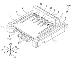
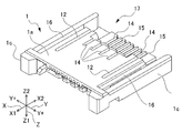
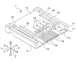
- FIG. 1A is a perspective view of the connector 100 according to the embodiment of the present invention.
- FIG. 1B is a perspective view of FIG. 1A viewed from a different direction.
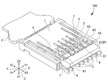
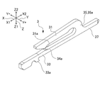
- FIG. 2A is a perspective view showing a state in which the connection target F is inserted into the connector 100 by omitting a housing and the like virtually.
- FIG. 2B is a view showing a state in which the connection target F is inserted into the connector 100 by virtually omitting the housing and the like, and is a cross-sectional view of the contact 4 with the fixing function cut along the XZ plane.
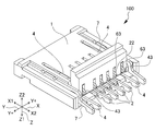
- FIG. 3A is a perspective view when the connection target F is inserted into the connector 100 and the pressing member 6 is in the first pressing member posture.
- FIG. 3B is a view of FIG.
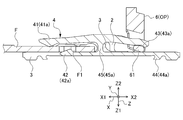
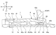
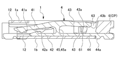
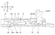
- FIG. 4A is a cross-sectional view of the contact 4 with a fixing function held in the housing 1 taken along the XZ plane, and is a diagram when the pressing member 6 is in the second pressing member posture.
- FIG. 4B is a cross-sectional view of the contact with fixing function 4 held in the housing 1 taken along the XZ plane, and is a diagram when the pressing member 6 is in the first pressing member posture.
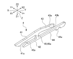
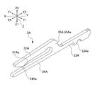
- FIG. 5 is a perspective view of the contact 4 with a fixing function according to the first embodiment.
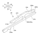
- FIG. 6 is a perspective view of a contact 4A with a fixing function according to the second embodiment.
- FIG. 7A is a cross-sectional view of the first signal contact 2 held in the housing 1 cut along the XZ plane when the pressing member 6 is in the second pressing member posture.
- FIG. 7B is a perspective view of the first signal contact 2.
- FIG. 8 is a perspective view showing the second signal contact 2A.
- FIG. 9 is a perspective view showing the third signal contact 3A.
- FIG. 10A is a cross-sectional view of the fourth signal contact 3 held in the housing 1 taken along the XZ plane when the pressing member 6 is in the second pressing member posture.
- FIG. 10B is a perspective view of the fourth signal contact 3.
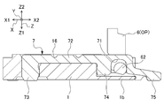
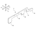
- FIG. 11A is a sectional view of the fixing bracket 7 held in the housing 1 taken along the XZ plane.
- FIG. 11B is a perspective view of the fixture 7.
- FIG. 12A is a perspective view of the housing 1.
- FIG. 12B is a perspective view of FIG. 12A viewed from a different direction.
- FIG. 13A is a perspective view of the pressing member 6.
- FIG. 13B is a perspective view of FIG. 13A viewed from a different direction.
- FIGS. 1A and 1B are perspective views of the connector 100 according to the embodiment of the present invention as viewed from different directions.
- 2A and 2B are views showing a state in which the connection target F is inserted into the connector 100 by virtually omitting a housing and the like.
- FIG. 2A is a perspective view
- FIG. 2B is an XZ plane. It is sectional drawing which cut
- FIGS. 3A and 3B are perspective views when the connection object F is inserted into the connector 100 and the pressing member 6 is in the first pressing member posture, as viewed from different directions.
- 4A and 4B are cross-sectional views of the contact with fixing function 4 held in the housing 1 taken along the XZ plane, and FIG. 4A is a diagram when the pressing member 6 is in the second pressing member posture.
- FIG. 4B is a diagram when the pressing member 6 is in the first pressing member posture.
- FIG. 5 is a perspective view of the contact 4 with a fixing function according
- FIG. 6 is a perspective view of a contact 4A with a fixing function according to the second embodiment.
- FIG. 7A is a cross-sectional view of the first signal contact 2 held in the housing 1 taken along the XZ plane when the pressing member 6 is in the second pressing member posture.
- FIG. 7B is a sectional view of the first signal contact.
- FIG. 2 is a perspective view of FIG.
- FIG. 8 is a perspective view showing the second signal contact 2A.
- FIG. 9 is a perspective view showing the third signal contact 3A.
- FIG. 10A is a cross-sectional view of the fourth signal contact 3 held in the housing 1 taken along the XZ plane when the pressing member 6 is in the second pressing member posture.
- FIG. 10B is a sectional view of the fourth signal contact.
- FIG. 11A is a cross-sectional view of the fixing bracket 7 held in the housing 1 taken along the XZ plane
- FIG. 11B is a perspective view of the fixing bracket 7.
- 12A and 12B are perspective views of the housing 1 as viewed from different directions.
- 13A and 13B are perspective views of the pressing member 6 viewed from different directions.
- the connector 100 is mounted on a board (not shown), and is a connector to which a connection object F is removably inserted and connected. As shown in FIGS. 1A to 3B, the connector 100 is mainly inserted with the connection object F so as to be substantially parallel to a board mounting surface (not shown) in a state where the connection object F is inserted. And a predetermined number of signal contacts (first signal contact 2, fourth signal contact 3, contact 4 with fixing function) held in parallel with housing 1, and insertion into housing 1. And a pressing member 6 which is located on the opposite side of the mouth 11 and has a shape that can be pressed against the signal contacts 2 and 4.
- substantially parallel is not limited to a case in which the object is completely parallel to a board mounting surface (not shown), and may be approximately parallel in at least an approximate direction. Is intended to distinguish it from a form substantially perpendicular to the substrate mounting surface.
- the “opposite side of the insertion port 11” is the same side as the “side on which the pressing member 6 is operated” and the “side on which the pressing member 6 is (has)”.
- the X direction is a direction extending in the insertion / removal direction of the connection target, and is a direction substantially parallel to the board mounting surface.
- the X1 side is the side of the insertion port 11
- the X2 side is the opposite side to the X1 side.
- the Y direction is a parallel direction (arrangement pitch direction) of a predetermined number of signal contacts, and is also referred to as a lateral direction (longitudinal direction).
- the Y + side is the outer side in the Y direction with respect to the housing 1 (left side / right side is not distinguished).
- the Z direction is a direction orthogonal to the X direction and the Y direction, and is also referred to as a height direction.
- the Z1 side is the board mounting surface side
- the Z2 side is the side away from the board mounting surface.
- the XYZ coordinate system is used for the convenience of the description of the embodiment, and is not strictly interpreted unless it violates the gist of the present invention.
- connection object F is an object that is detachably inserted into and connected to the connector 100, and is, for example, a flexible printed circuit board (FPC), a flexible flat cable (FFC), or a card having flexibility.
- the connection object F includes a land portion F2 that contacts at least the respective contact portions of the signal contacts 2, 3, and 4, a pattern connected from the land portion F2 to the circuit, and a locked state. And a section F1.
- the locked portion F1 increases the holding force of the connection target F and prevents the connection target F from coming off.
- the signal contacts 3 and 4 are sandwiched in the parallel direction (Y direction), and the contacts (LC) 4 with the fixing function arranged in pairs at the outermost (Y + side) are engaged. It is a part to do.
- the locked portion F1 is on the insertion direction side (X1 side) in the insertion / removal direction (X direction) of the connection object F to / from the connector 100, and with respect to the insertion / removal direction. It is provided on both outer sides (Y + side) in the horizontal direction (Y direction).
- the shape of the locked portion F1 is not particularly limited as long as it can be engaged with a locking portion (LC2) 42a of a locking leg 42 of the contact (LC) 4 with a fixing function, which will be described later.
- the connection object F may be formed as a cutout portion cut out from the side, or may be formed as a through hole or a stop hole depending on specifications.
- the housing 1 has an insertion port 11 through which the connection object F is inserted and withdrawn, and holds the signal contacts 2, 3, and 4.
- the housing 1 is formed from an electrically insulating material (for example, plastic).
- the housing 1 is manufactured as one member by injection molding of a known technique. Specifically, the material of the housing 1 is appropriately selected in consideration of dimensional stability, workability, cost, and the like. In general, for example, polybutylene terephthalate (PBT), polyamide (66PA, 46PA), liquid crystal Examples include polymer (LCP), polycarbonate (PC), polyphenylene sulfide (PPS), and synthetic materials thereof.
- the signal contacts 2, 3, 4 are held in the housing 1 in a parallel arrangement. Among them, the signal contacts 2 and 4 are changed from the second pressing member posture OP (see FIGS. 1A and 2B) to the first pressing member posture CP (see FIGS. When the state changes to (see FIGS. 3A and 3B), a stable contact is made with the land portion F2 of the connection target F. In the case of the signal contacts 2 and 4, even if the land F 2 contacts the land F 2 in a state where the connection target F is inserted, stable contact is not achieved, and stable contact is achieved only when the state of the pressing member 6 changes. .
- the state change includes not only a simple rotation in which the rotation axis does not move, but also a rotation accompanied by a movement of the rotation axis and a movement not including the rotation.
- the signal contacts 2, 3, and 4 are different types of contacts. Specifically, the signal contacts 2, 3, and 4 shown in FIGS. 7A and 7B have a connection portion on the opposite side (X2 side) of the insertion port 11 (the X2 side). 1 signal contact 2), a type (fourth signal contact 3) shown in FIGS. 10A and 10B in which the connection portion is located on the insertion port 11 side (X1 side), and a lock shown in FIGS. 4A to 5 This is a contact (LC) 4 with a fixing function that also serves as a member.
- LC contact
- the first signal contacts 2 and the fourth signal contacts 3 are alternately arranged in a staggered manner on the XY plane with different insertion directions into the housing 1. That is, the connection portions are alternately arranged in a staggered manner. Since the material of the signal contacts 2, 3, and 4 is required to have spring property and conductivity, brass, beryllium copper, phosphor bronze, and the like can be given.
- the contacts with fixing function 4 and 4 are paired at positions on the Y + side in the housing 1 and the signal contacts 2 and 3 in the Y direction in the embodiment. Has been held.
- the arrangement positions of the fixing-function-equipped contacts 4 and 4 are appropriately designed in consideration of the holding force and balance of the connection target F.
- the contacts 4 with the fixing function are arranged so as to form a pair at both ends of the housing 1.
- the arrangement position may be any one of the positions. May be one place.
- the pressing member 6 is located on the opposite side (X2 side) of the housing 1 from the insertion opening 11 and has a shape portion that can be pressed against the first signal contact 2 and the contact 4 with the fixing function.
- the insertion port side (the side of the insertion port 11) is a side where the insertion port 11 is arranged with respect to the center of the housing 1 in the insertion / removal direction X of the object to be connected.
- the opposite side of the insertion port 11 is the side opposite to the insertion port side (the side of the insertion port 11) with respect to the center portion of the housing 1 in the insertion / removal direction X of the object to be connected.
- the insertion port side (the side of the insertion port 11) and the opposite side of the insertion port 11 with respect to the center portion of the housing 1 are in a relationship arranged in the insertion / removal direction X of the object to be connected. Note that the pressing member 6 does not press the fourth signal contact 3.
- the pressing member 6 is made of an electrically insulating plastic material, and is manufactured by injection molding of a known technique. Specifically, the material of the pressing member 6 is appropriately selected in consideration of dimensional stability, workability, cost, and the like. In general, polybutylene terephthalate (PBT), polyamide (66PA, 46PA), liquid crystal, or the like is used. Examples include polymer (LCP), polycarbonate (PC), polyphenylene sulfide (PPS), and synthetic materials thereof.
- the connector 100 of the present embodiment further includes the fixture 7 to increase the mounting strength of the board.
- the fixing bracket 7 is provided at a position further Y + side than the contact 4 with the fixing function.
- the fixture 7 is held in the housing 1 separately from the contacts.
- the first fixing function-equipped contact 4 has both the function of electrically connecting to the connection object F and the function of locking, and can be regarded as a lock member that can be used to conduct.
- the contact 4 with the first fixing function is held in the housing 1 so as to extend along the insertion / removal direction X of the connection object F.
- the contacts 4 with the first fixing function are arranged as a pair on the outermost side (Y + side) in the parallel direction (width direction) Y of the signal contacts 2, 3, and 4 in the housing 1.
- the contact 4 with the fixing function is a groove 12 formed on the inner surface of the housing 1 facing the height direction Z and located on the Y + side among the grooves partitioned by the wall portion (see FIGS. 12A and 12B). ) Is held by press fitting.
- the contact 4 with a fixing function is inserted into the housing 1 from the opposite side (X2 side) of the insertion opening 11 toward the X1 side.
- the contact 4 with the first fixing function includes a contact portion (LC1) 41a that comes into contact with one surface of the connection target F and a connection target inserted into the connector 100 at a regular insertion position.
- a locking portion (LC2) 42a having a shape capable of engaging with the locked portion F1 formed on the F, and a board located on the opposite side (X2 side) of the insertion port 11 with respect to the locking portion 42a;
- (LC4) 44a mounted on the connector, a connecting portion (LC5) 45a located between the contact portion 41a and the connecting portion 44a, and the opposite side (X2 side) of the insertion port 11 from the contact portion (LC1) 41a.
- a pressing portion (LC3) 43a pressed by the pressing member 6.
- the locking portion (LC2) 42a has a shape protruding toward the locked portion F1 toward the Z2 side at a position corresponding to the locked portion F1 formed on the inserted connection target F.
- the pressing portion (LC3) 43a is located on the side (Z2 side) facing the connecting portion (LC4) 44a, extends on the opposite side (X2 side) from the contact portion 41a, and is pressed by the pressing member 6.
- the connection part (LC4) 44a extends on the opposite side (X2 side) from the locking part 42a and is connected to the substrate.
- the contact 4 with the first fixing function includes a contact leg 41 having a contact portion 41a, a locking leg 42 having a locking portion 42a, and a pressing leg 43 having a pressing portion 43a.
- a connecting leg 44 having a connecting portion 44a and a connecting leg 45 having a connecting portion 45a are integrally provided so as to form an H-shape as a whole.
- the contact leg 41, the connection leg 45, and the connection leg 44 are arranged in a substantially crank shape.
- the contact part 41a, the locking part 42a, the connecting part 44a, the connecting part 45a, and the pressing part 43a are integrally formed of the same metal material. More specifically, a contact leg 41 having a contact portion 41a, a locking leg 42 having a locking portion 42a, a pressing leg 43 having a pressing portion 43a, and a connecting leg having a connecting portion 44a. The portion 44 and the connecting leg 45 having the connecting portion 45a are integrally formed from the same metal material.
- the pressing leg 43 having the pressing portion 43 a can be pressed.
- the pressing portion 61 of the pressing member 6 is rotatably supported.
- rotation includes not only simple rotation in which the rotation axis does not move, but also rotation accompanied by movement of the rotation axis.
- the contact leg 41 comes into contact with the land F2 of the connection target F to enable electrical connection.
- the contact leg 41 is located in the groove 12 on the upper wall 1 a side (Z2 side) of the housing 1, and is located on the insertion opening 11 side (X1 side) of the housing 1 with respect to the connection leg 45. I have. That is, the contact leg 41 is located on the side (Z2 side) facing the locking leg 42 and extends toward the insertion port 11 (to the X1 side).
- the tip of the contact leg 41 on the insertion port 11 side is in a state of floating from the bottom surface of the groove 12 on the Z1 side, and is in contact with one surface of the connection object F (the surface on the Z2 side in the embodiment).
- the contact portion 41a has a shape protruding toward the Z1 side so that the contact portion 41a can easily come into contact with the connection target F.
- the contact leg 41 is displaced toward the connection object F. That is, when the connection object F is inserted by the pressing member performing such a state change in a state where the connection object F is not inserted, the contact portion 41a is pressed against the connection object F. This ensures reliable and stable electrical contact.
- the term “displacement” as used herein means that at least when the connection target F is not inserted, the displacement is performed, and includes displacement even when the connection target F is inserted.
- the locking leg portion 42 is engaged with a locked portion F1 formed on the connection object F to temporarily fix the connection object F at the regular insertion position.
- the locking leg 42 is disposed on the side of the groove 12 on the lower wall 1b side (Z1 side) of the housing 1 opposite to the contact leg 41, and is positioned on the insertion leg 11 side of the housing 1 with respect to the connecting leg 45. (X1 side). That is, the locking leg 42 extends toward the insertion port 11 (toward the X1 side). The locking leg 42 is held in the groove 12 so that a part thereof can be visually recognized from the insertion port 11 side.
- the locking leg 42 includes a locking portion 42a having a shape protruding toward the locked portion F1 at a position corresponding to the locked portion F1 formed on the connection target F inserted into the housing 1.
- the locking portion 42a is provided at a position corresponding to the locked portion F1 when the insertion of the connection target F is completed.
- the locking portion 42a is provided on the distal end side (X1 side) of the locking leg portion 42, extends upward in a tapered manner from the distal end portion of the locking leg portion 42, and then engages substantially vertically. It is formed so as to return to the stopping leg 42. That is, the locking portion 42a of the locking leg 42 protrudes from the groove 12 on the lower wall 1b side (Z1 side) of the held housing 1 toward the upper wall 1a toward the Z2 side.
- the positional relationship between the locking portion 42a and the contact portion 41a which is one of the features of the present invention, is as follows. As shown in FIGS. 4A to 5, the locking portion 42a is located at a position corresponding to the locked portion F1 of the connection target F, on the side closer to the substrate mounting surface (Z1 side), and away from the substrate mounting surface. (Z2 side). The contact portion 41a is located on the side facing the locking portion 42a, farther from the substrate mounting surface (Z2 side), and closer to the insertion side (X1 side) of the connection target than the locking portion 42a. I do.
- the pressing leg 43 is a portion that is pressed by the pressing portion 61 of the pressing member 6 and is displaced in a direction away from the substrate mounting surface (Z2 side).
- the pressing leg 43 is disposed on the side facing the connection leg 44 on the upper wall 1a side (X2 side) of the housing 1, and is opposite to the connection leg 45 from the insertion opening 11 of the housing 1. (X2 side). That is, the pressing leg 43 extends to the side where the pressing member is located on the opposite side (X2 side) of the insertion port 11.
- the pressing leg 43 has a pressing portion 43 a pressed by the pressing member 6.
- the central portion of the pressing members 6 in the parallel direction is opposite to the insertion opening 11 of the housing 1 (X2 side) due to the repulsive force due to the pressing of the pressing members 6.
- a swelling prevention means for preventing swelling and movement also referred to as “swelling movement”.
- a protruding portion 43b that protrudes toward the connecting leg 44 toward the Z1 side to prevent the pressing member 6 from swelling and moving is provided at a tip portion on the X2 side of the pressing leg 43. ing.
- the center of the pressing member 6 in the width direction Y of the housing 1 tends to swell (approach) in the direction opposite to the insertion opening 11 of the housing 1 (X2 side).
- a tendency can be suppressed by providing the protruding portion 43b of the pressing leg 43.
- the size of the protruding portion 43b is not particularly limited as long as it can fulfill the above role, and may be appropriately designed so that the pressing portion 61 of the pressing member 6 is caught.
- the swelling preventing means may include a groove (recess) for receiving the pressing portion 61 and a protrusion (protrusion or projection) on the opposite side of the projection (not shown). .
- connection leg 44 is a leg-shaped portion mounted (connected) to a board (not shown).
- the connecting leg portion 44 is located on the side of the groove 12 on the lower wall portion 1b side (Z1 side) of the housing 1 opposite to the pressing leg portion 43. It is located on the opposite side (X2 side) of the insertion slot 11. That is, the connection leg 44 extends on the opposite side (X2 side) of the insertion port 11.
- the connection leg portion 44 has a connection portion 44a mounted (connected) to the substrate.
- the connection portion 44a is formed on the tip end side (X2 side) of the connection leg portion 44 on the opposite side (Z1 side) from the side facing the pressing leg portion 43.
- the connecting portion 44a is of a surface mount type (SMT) in the illustrated embodiment, but may be of a dip type or a press fit.
- SMT surface mount type
- the connecting leg 45 has a connecting portion 45a that connects the contact leg 41, the locking leg 42, the pressing leg 43, and the connecting leg 44 to each other.
- the connecting leg 45 is described as connecting the legs 41 to 44 to each other for convenience of explanation. However, the entire contact 4 with a fixing function is formed of one member, and the connecting leg 45 and other There is no clear distinction between the leg and the border.
- the contact 4A with the second fixing function of the second embodiment is inserted into the housing 1 from the insertion opening 11 side (from the X1 side to the X2 side) as shown in FIG.
- the contact 4 ⁇ / b> A with the second fixing function is different from the contact 4 with the first fixing function mainly in that the connecting portion 44 ⁇ / b> Aa (the connecting leg portion 44 ⁇ / b> A) is disposed on the X ⁇ b> 1 side and the extending portion 47 is provided.
- the configuration is provided with the extension leg portion 47.
- the present invention is not limited to this, and the configuration may be such that the extension leg portion 47 is not provided, or the extension leg portion may be extended along the insertion / extraction direction X.
- the length of 47 may be shorter than that of the pressing leg 43.
- the positional relationship between the locking portion 42Aa and the contact portion 41Aa which is one of the features of the present invention, is the same as that of the contact 4 with the first fixing function.
- the locking portion 42 ⁇ / b> Aa is located at a position corresponding to the locked portion F ⁇ b> 1 of the connection target F on the side closer to the substrate mounting surface (Z1 side) and from the substrate mounting surface. It protrudes in the direction away (Z2 side).
- the contact portion 41Aa is located on the side facing the locking portion 42Aa, farther from the substrate mounting surface (Z2 side), and closer to the insertion side (X1 side) of the connection target than the locking portion 42Aa. I do.
- the contact 4A with the second fixing function is located at a position corresponding to the contact portion 41Aa that comes into contact with one surface of the connection target F and the locked portion F1 formed on the inserted connection target F.
- a locking portion 42Aa having a shape protruding toward the locked portion F1 toward the Z2 side, a connecting portion 45Aa connecting the contact portion 41Aa and the locking portion 42Aa, and a side facing the extended leg portion 47 ( Z2), extends on the opposite side (X2 side) from the contact portion 41Aa, and is pressed by the pressing member 6 from the pressing portion 43Aa to the insertion portion 11A (X1 side) from the locking portion 42Aa.
- a connecting portion 44Aa extending further toward the substrate.
- the contact 4A with the second fixing function includes a contact leg 41A having a contact portion 41Aa, a locking leg 42A having a locking portion 42Aa, a pressing leg 43A having a pressing portion 43Aa, and a connecting portion.
- a connecting leg portion 44A having a connecting portion 44Aa, a connecting leg portion 45A having a connecting portion 45Aa, and an extending leg portion 47 extending toward the X2 side are integrally provided so as to form an H-shape as a whole.
- the extension legs 47 are not provided, the legs are integrally provided so as to form an h-shape as a whole.
- the contact leg 41A, the connection leg 45A, and the connection leg 44A are arranged in a substantially U-shape.
- the extension leg portion 47 is a leg-like portion extending on the same side as the locking leg portion 42A in the height direction Z of the housing 1 and on the side (X2 side) opposite to the insertion port where the pressing member 6 is located. It is.
- the extension leg 47 supports the rotation of the pressing portion 61 of the pressing member 6 together with the pressing leg 43A. Note that the extension legs 47 may not be provided.
- a predetermined number of the first signal contacts 2 are held in the housing 1 in a state where they are arranged in parallel in the lateral direction Y, and are disposed between the pair of first fixed function contacts 4.
- the first signal contact 2 is press-fitted into a groove 14 (see also FIGS. 12A and 12B) of a groove formed on an inner surface of the housing 1 facing the height direction Z and partitioned by a wall. Is held by The first signal contact 2 is inserted into the housing 1 from the opposite side of the insertion opening 11 (from the X2 side to the X1 side).
- the first signal contact (NSC1) 2 is a simple signal contact (NSC) that is a signal contact that is not a lock member (the same applies to a second signal contact 2A, a third signal contact 3A, and a fourth signal contact 3 described later).
- the first signal contact 2 includes a first contact portion (NSC1-1) 21a that contacts at least one of the two surfaces of the connection target F (the surface on the Z2 side in the embodiment), A first connection part (NSC1-4) 23a, which is located on the opposite side (X2 side) of the insertion port 11 with respect to the first contact part 21a and is mounted on the board; a first contact part 21a and a first connection part 23a And a first pressing portion extended from the first contact portion 21a to the opposite side (X2 side) of the insertion port 11 and pressed by the pressing member 6. (NSC1-3) 22a and a first extension leg 24 extending toward the X1 side.
- the first signal contact 2 includes a first contact leg 21 having a first contact portion 21a, a first pressing leg 22 having a first pressing portion 22a, and a first connecting portion 23a.
- a first connecting leg 25 having a first connecting portion 25a, and a first extending leg 24 are integrally provided so as to form an H-shape as a whole.
- each leg portion is integrally provided so as to form an h-shape as a whole.
- the first contact leg 21 having the first contact portion 21a, the first connection leg 25 having the first connection portion 25a, and the first connection leg 23 having the first connection portion 23a are substantially cranked. Arranged in shape.
- the first signal contact 2 does not have a locking portion (locking leg), and instead extends to the insertion port 11 side (X1 side).
- One extension leg 24 is provided, and has an H-shape as a whole.
- the pressing portion 61 of the pressing member 6 rotates so that the connection target F is inserted and the first pressing leg portion 22 having the first pressing portion (NSC1-3) 22a can be pressed. Supported as possible.
- the second signal contact (NSC2) 2A is not provided in the connector 100 shown in FIGS. 1A and 1B, but can be provided in a suitable housing 1.
- the part of the second signal contact 2A having the same name as the part of the first signal contact 2 has the same configuration and function as the first signal contact 2, and thus the description may be omitted.
- the predetermined number of second signal contacts 2A are held in the housing 1 in a state of being arranged in parallel in the horizontal direction Y.
- the second signal contact 2A is press-fitted into a groove (not shown) formed on an inner surface of the housing 1 facing the height direction Z and partitioned by a wall.
- the second signal contact 2A is inserted into the housing 1 from the insertion opening 11 side (from the X1 side to the X2 side).
- the second signal contact 2A includes a second contact portion (NSC2-1) 21Aa that contacts at least one of the two surfaces of the connection target F, and a side (X1) of the insertion port 11 with respect to the second contact portion 21Aa. Side), a second connection portion (NSC2-4) 23Aa mounted on the board, and a second connection portion (NSC2-5) 25Aa located between the second contact portion 21Aa and the second connection portion 23Aa. Is located on the side (Z2 side) facing the second extension leg 27A described later, extends from the second contact portion 21Aa to the opposite side (X2 side) of the insertion port 11, and is pressed by the pressing member 6. A second pressing portion (NSC2-3) 22Aa and a second extending leg portion 27A extending to the X2 side.
- the second signal contact 2A includes a second contact leg 21A having a second contact portion 21Aa, a second pressing leg 22A having a second pressing portion 22Aa, and a second connecting portion 23Aa.
- a second connecting portion having a second connecting portion 25Aa, and a second extending leg 27A are integrally provided so as to form an H-shape as a whole.
- each leg is integrally provided so as to form an h-shape as a whole.
- the second contact leg 21A having the second contact portion 21Aa, the second connection leg 25A having the second connection portion 25Aa, and the second connection leg 23A having the second connection portion 23Aa are substantially It is arranged in a letter shape.
- the second signal contact 2A has an H-shaped shape as a whole, although the positional relationship in the insertion / extraction direction X between the connection portion (connection leg portion) and the extension leg portion is opposite to that of the first signal contact 2. ing.
- the pressing portion 61 of the pressing member 6 rotates so that the connection target F is inserted and the second pressing leg 22A having the second pressing portion (NSC2-3) 22Aa can be pressed. Supported as possible.
- the third signal contact (NSC3) 3A is not provided in the connector 100 shown in FIGS. 1A and 1B, but can be provided in a suitable housing 1.
- the portion of the third signal contact 3A having the same name as the portion of the first signal contact 2 and the second signal contact 2A has the same configuration and function as the first signal contact 2 and the second signal contact 2A. The description may be omitted.
- the predetermined number of third signal contacts 3A are held in the housing 1 in a state of being arranged in parallel in the horizontal direction Y.
- the third signal contact 3A is press-fitted into a groove (not shown) formed on the inner surface of the housing 1 facing the height direction Z and partitioned by a wall.
- the third signal contact 3A is inserted into the housing 1 from the opposite side of the insertion opening 11 (from the X2 side to the X1 side).
- the third signal contact 3A includes a third contact portion (NSC3-1) 31Aa that contacts at least one of the two surfaces of the connection target F, and an opposite side of the insertion port 11 with respect to the third contact portion 31Aa ( X3), a third connection part (NSC3-4) 33Aa mounted on the board, and a third connection part (NSC3-5) located between the third contact part 31Aa and the third connection part 33Aa.
- NSC3-1) that contacts at least one of the two surfaces of the connection target F, and an opposite side of the insertion port 11 with respect to the third contact portion 31Aa ( X3)
- a third connection part (NSC3-4) 33Aa mounted on the board and a third connection part (NSC3-5) located between the third contact part 31Aa and the third connection part 33Aa.
- the third opposing contact portion 34Aa is located at a position opposing the third contact portion 31Aa in the height direction Z of the housing 1, and the other of the third contact portion 31Aa on the opposite side to the one surface contacting the connection target F. Contacts the connection object F on the surface of The third opposing contact portion 34Aa has a shape protruding toward the Z2 side toward the third contact portion 31Aa.
- the third opposing contact portion 34Aa only needs to be able to contact the connection target F by pressing by the pressing member 6 so that the third contact portion 31Aa can be stably connected to the connection target F.
- the third contact portion 31Aa and the housing 1 may be provided at a position shifted in the insertion / removal direction X direction from the position facing the height direction Z.
- the third signal contact 3A has a third contact leg 31A having a third contact portion 31Aa, a third connection leg 33A having a third connection portion 33Aa, and a third connection portion 35Aa.
- the third connecting leg 35A and the third extending leg 34A are integrally provided so as to form an h-shape as a whole.
- the third contact leg 31A having the third contact portion 31Aa, the third connection leg 35A having the third connection portion 35Aa, and the third connection leg 33A having the third connection portion 33Aa are substantially cranks. Arranged in shape.
- the third signal contact 3A does not have a pressing portion, and thus has an h-shape as a whole.
- the connection target F is inserted between the third contact leg 31A and the third extension leg 34A.
- a predetermined number of the fourth signal contacts 3 are held in a state where they are arranged in the housing 1 in parallel in the horizontal direction Y, and are disposed between the pair of first fixed function contacts 4. Are located in The fourth signal contact 3 is held by press-fitting in a groove 15 formed on an inner surface of the housing 1 facing the height direction Z and partitioned by a wall. The fourth signal contact 3 is inserted into the housing 1 from the insertion opening 11 side (from the X1 side to the X2 side).
- the fourth signal contact 3 includes a fourth contact portion (NSC4-1) 31a that contacts at least one of the two surfaces of the connection object F (the surface on the Z2 side in the embodiment), and a fourth contact portion.
- the fourth connection portion (NSC4-4) 33a which is located on the side of the insertion port 11 (X1 side) with respect to the insertion hole 11a and is mounted on the board, is located between the fourth contact portion 31a and the fourth connection portion 33a.
- the fourth signal contact 3 has a fourth contact leg 31 having a fourth contact portion 31a, a fourth connection leg 33 having a fourth connection portion 33a, and a fourth connection portion 35a.
- the fourth connecting leg 35 and the fourth extending leg 37 are integrally provided so as to form an h-shape as a whole.
- the fourth contact leg 31 having the fourth contact portion 31a, the fourth connecting portion having the fourth connecting portion 35a, and the fourth connecting leg 33 having the fourth connecting portion 33a are substantially U-shaped. Placed in The fourth opposing contact portion 34a is located between the fourth connection portion 33a and the fourth connection portion 35a in the insertion / extraction direction X.
- the fourth signal contact 3 has a h-shaped shape as a whole, although the positional relationship in the insertion / extraction direction X between the connection portion (connection leg portion) and the extension leg portion is opposite to that of the third signal contact 3A. ing.
- the connection target F is inserted between the fourth contact leg 31 and the fourth connection leg 33.
- the fixture 7 will be described with reference to FIGS. 11A and 11B.
- the fixing bracket 7 is provided at a position further on the Y + side than the contact 4 with a fixing function.
- the fixture 7 is held in the housing 1 separately from the contacts. Specifically, as shown in FIGS.
- the fixture 7 includes a base 72 extending in the X direction, a first protruding piece 73 protruding from the X1 side to the Z1 side of the base 72, A second projecting piece 74 projecting from the base 72 to the Z1 side on the X2 side of the projecting piece 73, and a third projecting piece 75 projecting from the base 72 to the Z1 side on the X2 side of the second projecting piece 74. And a movement restricting portion 71 formed to be recessed in the Z2 direction from the base 72, the second projecting piece 74, and the third projecting piece 75. The tip side of the third protruding piece 75 extends substantially toward the X2 side.
- a part of the housing 1 is sandwiched between the first projecting piece 73 and the second projecting piece 74 in the insertion / extraction direction X, and the fixture 7 is fixed to the housing.
- the Z1 side tip of the first projecting piece 73 and the Z1 side tip of the third projecting piece 75 are mechanically connected to the substrate.
- a lower wall portion 1b of the housing 1 is disposed at an opening portion on the Z1 side of the movement restricting portion 71, and a hole formed by an inner peripheral edge of the movement restricting portion 71 and an upper edge of the lower wall portion 1b is provided.
- the shaft portion 62 of the pressing member 6 is arranged. By disposing the shaft portion 62 of the pressing member 6 with the movement range regulated by the hole, the movement range of the pressing member 6 is regulated and the pressing member 6 becomes rotatable.
- the housing 1 has a pair (two) in the lateral direction X connecting the upper wall 1a and the lower wall 1b, and an upper wall 1a and a lower wall 1b located opposite to each other in the height direction Z of the housing 1.
- the insertion opening 11 of the housing 1 is defined by an upper wall 1a, a lower wall 1b, and two side walls 1c.
- the housing 1 has a plurality of grooves for holding the first signal contact 2, the fourth signal contact 3, the contact 4 with a fixing function, and the fixing bracket 7, respectively. These grooves are provided with a groove 12 for holding the contact 4 with a fixing function and a first signal contact 2 at positions facing the inner surfaces of the upper wall portion 1a and the lower wall portion 1b facing the height direction Z of the housing 1, respectively. It is formed as a groove 14 for holding, a groove 15 for holding the fourth signal contact 3, and a groove 16 for holding the fixture 7.
- each of the grooves 12, 14, and 15 is formed to penetrate the housing 1 in the extending direction (X direction) of the contacts 2, 3, and 4. Is shown.
- the signal contacts 2, 3, 4 and the fixing member 7 are fixed in the corresponding grooves 14, 15, 12, 16 by press-fitting, hooking (lance), welding, or the like, respectively.
- a notch 17 is formed in the upper wall 1a of the housing 1.
- the upward displacement of the pressing leg portions 22 and 43 is not hindered.
- the size of the notch 17 is appropriately designed in consideration of the above-mentioned role, reduction in the height of the connector 100, workability, strength, and the like.
- the pressing member 6 presses the pressing portion 43a of the contact 4 with the fixing function and the first pressing portion 22a of the first signal contact 2, and releases the pressing CP.
- the second pressing member posture OP is rotatable.
- the second pressing member posture OP is a posture that allows the connection target F to be inserted into and removed from the housing 1.
- the first pressing member posture CP is a posture for stably maintaining the pressing contact state of the first signal contact 2 and the contact 4 with the fixing function with respect to the connection target F.
- the pressing member 6 presses the pressing portion 43a of the contact 4 with the fixing function and / or the first pressing portion 22a of the first signal contact 2 in the first pressing member posture CP.
- a pressing portion 61 extending in the parallel direction Y of the signal contacts 2, 3, and 4 where the pressing is performed, an opposing wall 64 facing the pressing portion 61 and extending in the parallel direction Y, A connecting wall 65 for connecting the opposing walls 64 at intervals in the parallel direction Y; and a pressing portion 43a of the contact 4 with a fixing function or / and a first signal contact 2 at least in the state of the second pressing member posture OP.
- a predetermined number of independent through holes 63 into which the first pressing portions 22a are inserted, and a shaft portion 62 rotatably mounted on the movement restricting portion 71 are provided.
- the through hole 63 is defined by the pressing portion 61, the opposing wall 64, and the connecting wall 65.
- the pressing member 6 includes a first pressing member posture CP that presses the pressing portion 43a of the contact 4 with the fixing function and / or the first pressing portion 22a of the first signal contact 2, and a pressing portion of the contact 4 with the fixing function. 43a and / or a second pressing member posture OP for releasing the pressing of the first pressing portion 22a of the first signal contact 2.
- the pressing in the first pressing member posture CP and the release of the pressing in the second pressing member posture OP are not simply distinguished by the presence or absence of contact between the pressing member 6 and various pressing portions.
- the pressing in the first pressing member posture CP is pressing such that the pressing contact state is stably maintained. If such a state has not been reached, it can be considered that the pressing has been released even if there is contact between the pressing member 6 and the various pressing portions.
- the pressing member 6 is pressed by the pressing portion 61 extending in the parallel direction Y, and the pressing portion 43 a of the contact 4 with the fixing function and / or the first pressing leg of the first signal contact 2.
- the pressing portion 61 is located at a position where the portion 22 is moved in a direction away from the board mounting surface (Z2 side) and pressure is applied to the pressing portion 43a of the contact 4 with the fixing function.
- the connector of the present invention may include a contact that is not pressed by the pressing portion 61 (pressable shape portion) of the pressing member 6, in other words, a contact that does not have a pressing portion, as in the embodiment.
- the pressing portion 43a of the contact 4 with the fixing function and / or the first pressing portion 22a of the first signal contact 2 are inserted into the through hole 63.
- the extended pressing portion 61 is a portion that presses the first pressing leg 22 of the first signal contact 2 and / or the pressing leg 43 of the contact 4 with the fixing function and pushes up in a direction away from the substrate mounting surface. is there.
- the shape of at least the portion of the pressing portion 61 that comes into contact with the first signal contact 2, the contact 4 with the fixing function, or the lower wall portion 1b of the housing 1 is not particularly limited as long as the above-described pushing can be performed.
- the pressing portion 61 may have an arc portion in a part thereof, and in this case, the arc portion corresponds to a rotation range between the second pressing member posture OP and the first pressing member posture CP of the pressing member 6. It is preferable to form it.
- the shape of the pressing portion 61 may be, for example, an elongated shape having a longitudinal direction or an elliptical shape having a long axis and a short axis. That is, the shape of the extended pressing portion 61 has a length change such as a length in any part, and it is sufficient that the above-described pushing can be performed.
- the -axis portion 62 is mounted on the movement restricting portion 71 and is for smoothly rotating the pressing member 6 between the second pressing member posture OP and the first pressing member posture CP. If the pressing portion 61 is appropriately supported by the first signal contact 2 and the contact 4 with the fixing function, and the rotation of the pressing member 6 can be performed without any trouble, the shaft portion 62 may not be provided.
- the through hole 63 has sufficient elasticity (spring) for the first pressing leg 22 of the first signal contact 2 and the pressing leg 43 of the contact 4 with the fixing function without increasing the size of the connector in the X1-X2 direction. It is a runaway to have sex.
- the through holes 63 are separated from each other by a connecting wall 65 and are provided separately and independently. By providing the through holes 63 independently, the rigidity of the pressing member 6 can be improved, and the deformation of the pressing member 6 during rotation of the pressing member 6 can be prevented.
- connection target F can be inserted between the contact leg 41 of the contact 4 with the fixing function and the locking leg 42 when the pressing member 6 is in the second pressing member posture OP.
- the contact leg 41 can be brought into electrical contact with the land F2 of the connection target F at the contact portion 41a.
- FIG. 4A in a state where the pressing member 6 is in the second pressing member posture OP, the contact portion 41a of the contact leg portion 41 can be brought into electrical contact with the connection target F. In this case, Contact is not stable.
- the pressing member 6 is rotated to the first pressing member posture CP shown in FIG. 4B to stabilize the electrical connection between the contact 4 with fixing function and the connection target F, and Make sure to prevent removal.
- the pressing leg portion 43 of the contact 4 with the fixing function is moved upward (Z2 Side) and tilted and displaced.
- the contact leg 41 is displaced downward (Z1 side).
- the connection target F is sandwiched and fixed between the contact portion 41a of the contact leg 41 and the locking leg 42 so that the contact portion 41a is positioned on one side of the connection target F.
- the electrically stable contact is formed.
- the contact portion 41a of the contact leg 41 comes into pressure contact with the connection target F. Since the connection target F is pressed downward by the pressing of the connection target F by the contact portion 41a of the contact leg 41, the locking portion 42a of the locking leg 42 causes the connection target F to cover the connection target F. The connection portion F1 is securely locked, and the connection target F is reliably prevented from being pulled out. Thereby, more stable electrical contact is achieved between the contact portion 41a of the contact leg 41 and the connection target F.
- the contact portion 41a, the locking portion 42a, the connecting portion 44a, and the pressing portion 43a are integrally formed from the same metal material, and the lock member is a fixed conductive member.
- At least one functional contact 4 is included, and the locking portion 42a is separated from the substrate mounting surface on the side (Z1 side) closer to the substrate mounting surface at a position corresponding to the locked portion F1 of the connection target F.
- the contact portion 41a is on the side facing the locking portion 42a, on the side farther from the board mounting surface (Z2 side), and on the side of the connection target F than the locking portion 42a. It is located near the insertion side (X1 side).
- the retaining force with the connection target F can be increased by locking the locking portion 42a to the locked portion F1. Since the number of signal contacts can be reduced by using the lock member for the signal contacts, the dimension of the contacts 2, 3, and 4 in the parallel direction Y can be reduced (narrow pitch), and more signal contacts 2, 3, 4 can be arranged. Since the contact portion 41a is located at a position closer to the insertion side (X1 side) of the connection target F than the locking portion 42a, the pattern of the connection target F can be easily formed.
- One or more contacts 4 (lock members) with a fixing function can be provided on the inner side (closer to the center) in the lateral direction Y. Thereby, the lock function (holding force) can be improved.
- an extended leg portion may be provided on the X1 side of the locking portion 42a. The extending leg located on the Z1 side with respect to the pressing leg of the various contacts may not be provided.
- the simple signal contact one or more of the first signal contact 2, the second signal contact 2A, the third signal contact 3A, and the fourth signal contact 3 can be provided. It is preferable that the first signal contacts 2 and the second signal contacts 2A or the fourth signal contacts 3 are alternately arranged in a staggered manner. Similarly, it is preferable that the third signal contacts 3A and the second signal contacts 2A or the fourth signal contacts 3 are alternately arranged in a staggered manner. This is because the connection portions can be efficiently arranged on the substrate, so that the mounting efficiency can be improved.
- connection portion of the lock member and the connection portion of the simple signal contact are arranged on opposite sides in the insertion / removal direction from the viewpoint of improving connection strength.
- the contact is not limited to the signal contact, and may be a power contact. Not all of the lock members need to be contacts with a fixing function, and some of the lock members may be members that are not contacts (members specialized for the lock function).
- the configuration into which the contact or the like is inserted is not limited to the groove (the groove 12, the groove 14, the groove 15, or the groove 16 in the embodiment) as long as it has a shape into which the contact or the like can be inserted, and may be, for example, a hole.
Landscapes
- Coupling Device And Connection With Printed Circuit (AREA)
- Details Of Connecting Devices For Male And Female Coupling (AREA)
Priority Applications (3)
| Application Number | Priority Date | Filing Date | Title |
|---|---|---|---|
| JP2019538542A JP6581752B1 (ja) | 2018-08-27 | 2019-04-22 | コネクタ |
| CN201980047315.2A CN112425009B (zh) | 2018-08-27 | 2019-04-22 | 连接器 |
| US17/268,861 US11322874B2 (en) | 2018-08-27 | 2019-04-22 | Connector |
Applications Claiming Priority (2)
| Application Number | Priority Date | Filing Date | Title |
|---|---|---|---|
| JP2018158085 | 2018-08-27 | ||
| JP2018-158085 | 2018-08-27 |
Publications (1)
| Publication Number | Publication Date |
|---|---|
| WO2020044654A1 true WO2020044654A1 (ja) | 2020-03-05 |
Family
ID=69644076
Family Applications (1)
| Application Number | Title | Priority Date | Filing Date |
|---|---|---|---|
| PCT/JP2019/017024 Ceased WO2020044654A1 (ja) | 2018-08-27 | 2019-04-22 | コネクタ |
Country Status (3)
| Country | Link |
|---|---|
| JP (1) | JP6858816B2 (enExample) |
| CN (1) | CN112425009B (enExample) |
| WO (1) | WO2020044654A1 (enExample) |
Families Citing this family (1)
| Publication number | Priority date | Publication date | Assignee | Title |
|---|---|---|---|---|
| TWI836252B (zh) * | 2021-08-09 | 2024-03-21 | 禾昌興業股份有限公司 | 連接器 |
Citations (5)
| Publication number | Priority date | Publication date | Assignee | Title |
|---|---|---|---|---|
| JP2006210050A (ja) * | 2005-01-26 | 2006-08-10 | Omron Corp | コネクタ |
| JP2006210051A (ja) * | 2005-01-26 | 2006-08-10 | Omron Corp | コネクタ |
| JP2011023236A (ja) * | 2009-07-16 | 2011-02-03 | Molex Inc | コネクタ |
| JP2016091804A (ja) * | 2014-11-05 | 2016-05-23 | 日本航空電子工業株式会社 | コネクタ |
| JP2017143000A (ja) * | 2016-02-10 | 2017-08-17 | 株式会社フジクラ | コネクタ |
Family Cites Families (7)
| Publication number | Priority date | Publication date | Assignee | Title |
|---|---|---|---|---|
| JP4159178B2 (ja) * | 1999-04-30 | 2008-10-01 | 日本圧着端子製造株式会社 | フレキシブル基板用コネクタ |
| JP2011171034A (ja) * | 2010-02-17 | 2011-09-01 | D D K Ltd | コネクタ |
| KR101198736B1 (ko) * | 2011-02-08 | 2012-11-12 | 교우세라 커넥터 프로덕츠 가부시키가이샤 | 커넥터 |
| JP5362765B2 (ja) * | 2011-04-19 | 2013-12-11 | 京セラコネクタプロダクツ株式会社 | コネクタ |
| JP2017059352A (ja) * | 2015-09-15 | 2017-03-23 | 第一精工株式会社 | コネクタ装置 |
| JP2017091600A (ja) * | 2015-11-02 | 2017-05-25 | 第一精工株式会社 | 電気コネクタ |
| JP6462634B2 (ja) * | 2016-06-27 | 2019-01-30 | 株式会社フジクラ | コネクタ |
-
2019
- 2019-04-22 CN CN201980047315.2A patent/CN112425009B/zh active Active
- 2019-04-22 WO PCT/JP2019/017024 patent/WO2020044654A1/ja not_active Ceased
- 2019-08-30 JP JP2019158592A patent/JP6858816B2/ja active Active
Patent Citations (5)
| Publication number | Priority date | Publication date | Assignee | Title |
|---|---|---|---|---|
| JP2006210050A (ja) * | 2005-01-26 | 2006-08-10 | Omron Corp | コネクタ |
| JP2006210051A (ja) * | 2005-01-26 | 2006-08-10 | Omron Corp | コネクタ |
| JP2011023236A (ja) * | 2009-07-16 | 2011-02-03 | Molex Inc | コネクタ |
| JP2016091804A (ja) * | 2014-11-05 | 2016-05-23 | 日本航空電子工業株式会社 | コネクタ |
| JP2017143000A (ja) * | 2016-02-10 | 2017-08-17 | 株式会社フジクラ | コネクタ |
Also Published As
| Publication number | Publication date |
|---|---|
| JP2020035748A (ja) | 2020-03-05 |
| CN112425009A (zh) | 2021-02-26 |
| JP6858816B2 (ja) | 2021-04-14 |
| CN112425009B (zh) | 2023-09-15 |
Similar Documents
| Publication | Publication Date | Title |
|---|---|---|
| JP6581752B1 (ja) | コネクタ | |
| US7140896B2 (en) | Connector | |
| CN102610951B (zh) | 连接器 | |
| US7828570B2 (en) | Connector having improved pivoting member design | |
| KR20130103354A (ko) | 커넥터 | |
| CN102195161B (zh) | 连接器 | |
| JP6356167B2 (ja) | コネクタ | |
| WO2020044654A1 (ja) | コネクタ | |
| JP4927454B2 (ja) | コネクタ | |
| JP2012084501A (ja) | 電気コネクタ | |
| US7341470B2 (en) | Electrical connector for flexible printed circuit boards | |
| US9172190B2 (en) | Connector | |
| US20090298345A1 (en) | Connector | |
| JP2006294394A (ja) | コンタクト及び該コンタクトを使用するコネクタ | |
| JP6874059B2 (ja) | コネクタ | |
| JP2009230942A (ja) | コンタクト及び該コンタクトを用いたコネクタ | |
| JP5107129B2 (ja) | コンタクト及び該コンタクトを用いたコネクタ | |
| JP5216505B2 (ja) | 位置決め部材、及び、位置決め構造 | |
| JP2019135725A (ja) | コネクタ | |
| JP2018137246A (ja) | コネクタ | |
| JP5577444B2 (ja) | コネクタ | |
| JP2003257518A (ja) | 電気コネクタ | |
| JP5203526B2 (ja) | コネクタ | |
| JP4644719B2 (ja) | コネクタ | |
| JP2008077994A (ja) | コネクタ |
Legal Events
| Date | Code | Title | Description |
|---|---|---|---|
| ENP | Entry into the national phase |
Ref document number: 2019538542 Country of ref document: JP Kind code of ref document: A |
|
| 121 | Ep: the epo has been informed by wipo that ep was designated in this application |
Ref document number: 19856346 Country of ref document: EP Kind code of ref document: A1 |
|
| NENP | Non-entry into the national phase |
Ref country code: DE |
|
| 122 | Ep: pct application non-entry in european phase |
Ref document number: 19856346 Country of ref document: EP Kind code of ref document: A1 |