WO2020044596A1 - テトラヒドロほう酸塩の製造方法、テトラヒドロほう酸塩の製造装置及びテトラヒドロほう酸塩 - Google Patents
テトラヒドロほう酸塩の製造方法、テトラヒドロほう酸塩の製造装置及びテトラヒドロほう酸塩 Download PDFInfo
- Publication number
- WO2020044596A1 WO2020044596A1 PCT/JP2019/004717 JP2019004717W WO2020044596A1 WO 2020044596 A1 WO2020044596 A1 WO 2020044596A1 JP 2019004717 W JP2019004717 W JP 2019004717W WO 2020044596 A1 WO2020044596 A1 WO 2020044596A1
- Authority
- WO
- WIPO (PCT)
- Prior art keywords
- plasma
- borate
- ball mill
- hydrogen
- mill container
- Prior art date
- Legal status (The legal status is an assumption and is not a legal conclusion. Google has not performed a legal analysis and makes no representation as to the accuracy of the status listed.)
- Ceased
Links
Images






Classifications
-
- C—CHEMISTRY; METALLURGY
- C01—INORGANIC CHEMISTRY
- C01B—NON-METALLIC ELEMENTS; COMPOUNDS THEREOF; METALLOIDS OR COMPOUNDS THEREOF NOT COVERED BY SUBCLASS C01C
- C01B6/00—Hydrides of metals including fully or partially hydrided metals, alloys or intermetallic compounds ; Compounds containing at least one metal-hydrogen bond, e.g. (GeH3)2S, SiH GeH; Monoborane or diborane; Addition complexes thereof
- C01B6/06—Hydrides of aluminium, gallium, indium, thallium, germanium, tin, lead, arsenic, antimony, bismuth or polonium; Monoborane; Diborane; Addition complexes thereof
- C01B6/10—Monoborane; Diborane; Addition complexes thereof
- C01B6/13—Addition complexes of monoborane or diborane, e.g. with phosphine, arsine or hydrazine
- C01B6/15—Metal borohydrides; Addition complexes thereof
- C01B6/19—Preparation from other compounds of boron
- C01B6/21—Preparation of borohydrides of alkali metals, alkaline earth metals, magnesium or beryllium; Addition complexes thereof, e.g. LiBH4.2N2H4, NaB2H7
-
- H—ELECTRICITY
- H01—ELECTRIC ELEMENTS
- H01J—ELECTRIC DISCHARGE TUBES OR DISCHARGE LAMPS
- H01J37/00—Discharge tubes with provision for introducing objects or material to be exposed to the discharge, e.g. for the purpose of examination or processing thereof
- H01J37/32—Gas-filled discharge tubes
-
- H—ELECTRICITY
- H05—ELECTRIC TECHNIQUES NOT OTHERWISE PROVIDED FOR
- H05H—PLASMA TECHNIQUE; PRODUCTION OF ACCELERATED ELECTRICALLY-CHARGED PARTICLES OR OF NEUTRONS; PRODUCTION OR ACCELERATION OF NEUTRAL MOLECULAR OR ATOMIC BEAMS
- H05H1/00—Generating plasma; Handling plasma
- H05H1/24—Generating plasma
- H05H1/2406—Generating plasma using dielectric barrier discharges, i.e. with a dielectric interposed between the electrodes
- H05H1/2431—Generating plasma using dielectric barrier discharges, i.e. with a dielectric interposed between the electrodes using cylindrical electrodes, e.g. rotary drums
Definitions
- the present disclosure relates to a method for producing tetrahydroborate, an apparatus for producing tetrahydroborate, and a tetrahydroborate.
- Patent Documents 1 and 2 disclose methods for producing tetrahydroborate by hydrogenating borate.
- a sodium metaborate powder and a magnesium powder are reacted for about 2 hours in a hydrogen atmosphere of about 550 ° C. and 2.3 MPa.
- sodium metaborate powder and granular aluminum are reacted for about 1 hour in a hydrogen atmosphere of about 300 ° C. and 1 MPa while rolling and grinding the granular aluminum.
- Patent Documents 1 and 2 since the atmosphere in the large-volume reaction vessel needs to be kept at a high temperature and a high pressure for one hour or more, it is necessary to continuously input a large amount of energy from the outside. Further, the methods disclosed in Patent Literatures 1 and 2 involve very high cost processes because magnesium and aluminum are consumed as consumables as reducing metals. Furthermore, the methods disclosed in Patent Literatures 1 and 2 require one hour or more for the processing time of one batch, so that productivity is not improved. As described above, in the field of tetrahydroborate production, a satisfactory production method has not yet been established from the viewpoint of industrial application.
- the present disclosure has been made in view of the above circumstances, and provides a novel method for producing tetrahydroborate.
- the present disclosure also provides a production apparatus used in the production method, and a tetrahydroborate obtained by the production method.
- One aspect of the present disclosure is a method for producing tetrahydroborate comprising a hydrotreating step of exposing borate to hydrogen plasma while pulverizing the borate.
- the hydrogen plasma may be generated using a source gas containing at least one of a hydrogen gas and a hydrocarbon gas.
- the hydrogen plasma may be a plasma obtained by a dielectric barrier discharge.
- a hydrogen plasma may be provided to the borate as a plasma jet.
- the hydrogen plasma may be a high temperature plasma.
- the borate in the hydrotreating step, may be exposed to hydrogen plasma while being pulverized while being heated.
- a reducing agent capable of binding to hydrogen may be simultaneously treated with borate.
- the borate may be sodium metaborate.
- the production method may further include a preheating step of heating the borate before the hydrotreating step.
- the production method may further include, before the hydrotreating step, a borate preparation step of reacting tetrahydroborate with water to obtain a borate.
- the production method may further include a borate preparation step of reacting tetrahydroborate with water to obtain a borate before the preheating step.
- the apparatus is a ball mill container having a processing chamber containing a grinding media and a borate therein, a driving unit for rotating the ball mill container, a gas supply unit for supplying a raw material gas to the processing chamber, and a power supply for applying a voltage.
- a dielectric member that forms at least a part of the inner wall surface of the processing chamber, at least one pair of electrodes connected to the dielectric member and to which a voltage is applied from a power supply, and an insulator that insulates the at least one pair of electrodes;
- a plasma generating unit wherein the driving unit pulverizes borate by rotating a ball mill container, the gas supply unit sets the processing chamber to a source gas atmosphere, and the plasma generating unit sets the processing chamber to a source gas atmosphere.
- Hydrogen plasma is generated on the surface of the dielectric member by dielectric barrier discharge based on the voltage applied from the power supply in the processing chamber, and borate is removed during rotation of the ball mill container. Exposure to oxygen plasma.
- the apparatus is capable of generating a plasma jet of hydrogen plasma by applying a voltage to a ball mill container having a processing chamber containing a grinding medium and a borate therein, a driving unit for rotating the ball mill container, and a voltage.
- a plasma generation unit having a plasma jet nozzle fixedly disposed in a processing chamber so as to jet a plasma jet to a pulverizing medium and a borate storage location accommodated in a plasma generator, a power supply for applying a voltage to the plasma generation unit, and a plasma generation unit
- a gas supply unit for supplying a raw material gas to the unit, the driving unit crushes borate by rotating a ball mill container, and a plasma jet nozzle is supplied from a voltage and a gas supply unit applied from a power supply.
- a plasma jet is generated based on the raw material gas, and the grinding media and To inject the plasma jet to the residence portion of the Usanshio.
- the apparatus includes a ball mill container having therein a processing chamber for accommodating grinding media and borate having electrical conductivity, a driving unit for rotating the ball mill container, a gas supply unit for supplying a raw material gas to the processing chamber, and a processing chamber.
- a power source for applying a voltage between the pair of electrodes wherein the driving unit pulverizes the borate by rotating the ball mill container, and energizes at least the pair of electrodes through the pulverized media that has flowed.
- the gas supply unit sets the processing chamber to the atmosphere of the source gas, and the plasma generation unit applies a voltage from the power supply in the processing chamber in the source gas atmosphere.
- Another aspect of the present disclosure is a tetrahydroborate having a composition represented by the following general formula (A) or (B).
- M is at least one selected from the group consisting of Li, Na and K
- x is 0.05 or more and less than 1.0
- y is 0.6 or more and less than 1.0
- Z is 4.0.
- N is at least one selected from the group consisting of Ca and Mg
- s is 0.05 or more and less than 1.0
- t is 1.2 or more and less than 2.0
- u Is 8.0 is a composition represented by the following general formula (A) or (B).
- a novel method for producing tetrahydroborate can be provided.
- an apparatus for producing tetrahydroborate can be provided.
- a tetrahydroborate obtained by the production method can be provided.
- FIG. 2 is a schematic view (front view) showing an example of a production apparatus of tetrahydroborate.
- FIG. 3 is a schematic view (side view) showing an example of a production apparatus for tetrahydroborate.
- FIG. 4 is a sectional view taken along line AA of FIG. 3 showing a manufacturing apparatus having a first plasma generation unit.
- FIG. 3 is a sectional view taken along line BB of FIG. 2 showing a manufacturing apparatus having a first plasma generation unit.
- FIG. 4 is a sectional view taken along line AA of FIG. 3 showing a manufacturing apparatus having a second plasma generation unit.
- FIG. 3 is a sectional view taken along line BB of FIG. 2 showing a manufacturing apparatus having a second plasma generation unit.
- FIG. 4 is a sectional view taken along line AA of FIG. 3 showing a manufacturing apparatus having a third plasma generation unit.
- FIG. 3 is a sectional view taken along line BB of FIG. 2 showing a manufacturing apparatus having a third plasma generation unit.
- FIG. 4 is a sectional view taken along line AA of FIG. 3 showing a manufacturing apparatus having a fourth plasma generation unit.
- FIG. 13 is a sectional view taken along line BB of FIG. 2 showing a manufacturing apparatus having a fourth plasma generation unit.
- FIG. 4 is a sectional view taken along line AA of FIG. 3 showing a manufacturing apparatus having a fifth plasma generation unit.
- FIG. 13 is a sectional view taken along the line BB of FIG. 2 showing a manufacturing apparatus having a fifth plasma generation unit.
- FIG. 4 is a sectional view taken along line AA of FIG. 3 showing a manufacturing apparatus having a sixth plasma generation unit.
- FIG. 13 is a sectional view taken along the line BB of FIG. 2 showing a manufacturing apparatus having a sixth plasma generation unit.
- the X and Y directions in the figure are horizontal directions, and the Z direction is a vertical direction.
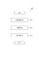
- FIG. 1 is a flowchart showing an example of a method for producing tetrahydroborate.
- the method MT shown in FIG. 1 is a method for producing tetrahydroborate using a borate as a raw material.
- the method MT has a borate adjustment step (Step S10), a preheating step (Step S12), and a hydrogenation step (Step S14).
- the borate adjustment step (Step S10) and the preheating step (Step S12) are not necessarily performed, but are performed as needed. Therefore, the hydrotreating step (Step S14) will be described first, and then the borate adjusting step (Step S10) and the preheating step (Step S12) will be described.
- the hydrotreating step is a step in which borate is exposed to hydrogen plasma while being ground.
- the borate is, for example, metaborate, tetraborate or pentaborate.
- the metaborate is, for example, NaBO 2 , KBO 2 , LiBO 2 , Ca (BO 2 ) 2 , or Mg (BO 2 ) 2 .
- the tetraborate is, for example, Na 2 B 4 O 7 , Na 2 O 2 BO 3 , K 2 O.B 2 O 3 , Li 2 B 4 O 7 , or Mg 3 B 4 O 9 .
- the pentaborate is, for example, NaB 5 O 8 , Na 2 O ⁇ 5B 2 O 3 , KB 5 O 8 , K 2 O ⁇ 5B 2 O 9 , or LiB 5 O 8 .
- Borate is a naturally occurring borate minerals Na 2 B 4 O 7 ⁇ 10H 2 O, Na 2 B 4 O 7 ⁇ 4H 2 O, Ca 2 B 6 O 11 ⁇ 5H 2 O, CaNaB 5 O 9 ⁇ 6H 2 O, Mg 7 Cl 2 B 17 O 30, etc.
- sodium metaborate NaBO 2
- NaBO 2 sodium metaborate
- Borate is a solid, and its shape is not particularly limited.
- the borate may be in powder form.
- the average particle size of the powdered borate can be 500 ⁇ m or less.
- the average particle size of the powdered borate may be 100 ⁇ m or less.
- the lower limit of the average particle size of the powdery borate is not particularly limited, but may be 5 ⁇ m.
- pulverization of borate is performed.
- the pulverization process is a process for converting borate into fine powder.
- a ball mill is used as an example.
- a borate and a pulverizing medium are contained in the same container, and the borate is pulverized by collision of the pulverizing medium.
- the ball mill means a ball mill in a broad sense (see the second edition of the Powder Engineering Handbook), a so-called rolling ball mill (pot mill, tube mill, and conical mill), a vibrating ball mill (circular vibration type vibration mill, turning) (Vibration mill and centrifugal mill), and a planetary mill.
- the borate in the pulverization process is exposed to hydrogen plasma as a hydrogen plasma process.
- Hydrogen plasma contains extremely active hydrogen radicals (H radicals) and hydrogen ions.
- H radicals extremely active hydrogen radicals
- the bond between the oxygen atoms of the borate is broken, and the oxygen atoms are removed.
- the hydrogen atom is bonded to the electron pair to which the oxygen atom has been bonded, whereby the borate is hydrogenated.
- sodium metaborate is used as the borate, the following reaction (1) is considered to occur in this step. NaBO 2 + 4H 2 ⁇ NaBH 4 + 2H 2 O (1)
- Hydrogen plasma used for the hydrogen plasma treatment is generated using a gas containing hydrogen (H) as a constituent element.
- hydrogen plasma can be generated using a source gas containing at least one of hydrogen gas and hydrocarbon gas.
- the hydrocarbon gas is, for example, CH 4 gas, C 2 H 2 gas, or C 6 H 6 gas.
- a gas containing an element that is more easily oxidized than hydrogen, such as a hydrocarbon is used, removal of oxygen atoms of borate is promoted. This is expected to increase the production rate of tetrahydroborate.
- the hydrogen plasma may be generated using NH 3 gas or the like.
- the source gas may include a gas containing an element that is more easily oxidized than hydrogen, such as carbon monoxide.
- a gas containing an element that is more easily oxidized than hydrogen such as carbon monoxide.
- the removal of the oxygen atoms of the borate is promoted as in the case where the hydrocarbon gas is employed. This is expected to increase the production rate of tetrahydroborate.
- the source gas may include a gas such as an argon gas, a helium gas, or a neon gas that causes a Penning effect in combination with hydrogen.
- a gas such as an argon gas, a helium gas, or a neon gas that causes a Penning effect in combination with hydrogen.
- the plasma concentration of the hydrogen plasma can be kept high, and the hydrogen plasma can be generated in a stable and wide range. This is expected to increase the production rate of tetrahydroborate.
- the hydrogen plasma treatment can be performed using, for example, a plasma generation apparatus generally used in a semiconductor process or the like.
- the pressure in the processing vessel to which the borate and the raw material gas are supplied is reduced to, for example, about 10 to 150 Pa. By controlling the pressure within the above range, hydrogen plasma having a high plasma density can be generated.
- Hydrogen plasma includes low-frequency plasma (plasma excited by a fluctuating voltage of 1 to 100 kHz), microwave plasma (plasma excited by microwave), and RF plasma (plasma excited by RF (Radio Frequency)). Any of them may be used. These plasmas may be pulse-excited plasmas or DC-excited plasmas.
- the optimum value of the frequency of the fluctuating voltage for exciting the low-frequency plasma can be selected according to the amount and state of the object to be processed and the pulverized media, and the shape and size of the processing container.
- the fluctuating voltage is adjusted using, for example, a variable frequency power supply. Since low-frequency plasma can be realized with a simple configuration, both apparatus cost and operation cost can be kept low.
- the frequency of the microwave used for exciting the microwave plasma is set to, for example, 1 GHz or more, which is a frequency band which can be used industrially and which can generate a thermal non-equilibrium hydrogen plasma having a high plasma density. Can be done. Thermally non-equilibrium plasma is so-called low-temperature plasma.
- a microwave having a frequency of 2.45 GHz is used.
- the electric power for exciting the microwave plasma can be 300 ° W or more.
- the processing time for borate plasma treatment depends on the amount of borate and the plasma density, but may be, for example, 1 hour or less, and may be 0.5 hour or less.
- reaction (1) oxygen atoms dissociated from borate react with hydrogen plasma to generate water.
- microwave plasma is excited using microwaves, water generated in the reaction (1) can be heated and evaporated or ionized effectively by microwaves. For this reason, it is possible to suppress a reverse reaction in which the produced tetrahydroborate reacts with water to return to borate. Thereby, the production rate of tetrahydroborate can be increased.
- the excitation frequency used to generate the RF plasma is generally 13.56 MHz in Japan from the viewpoint of legal regulations, but is not limited to this. Since RF plasma is widely used in industry, both apparatus cost and operation cost can be reduced. Since a wide range of hydrogen plasma is generated by the RF plasma, the production rate of tetrahydroborate can be increased.
- the hydrogen plasma may be a thermal equilibrium plasma.
- the plasma density and ion temperature of the hydrogen plasma can be increased, so that the effect of dissociating the oxygen atoms by cutting the bond between the oxygen atoms of the borate is enhanced.
- the production rate of tetrahydroborate can be increased.
- the thermal equilibrium hydrogen plasma is also called high-temperature plasma.
- water generated in reaction (1) can be effectively evaporated or ionized with high energy. For this reason, it is possible to suppress a reverse reaction in which the produced tetrahydroborate reacts with water to return to borate. Thereby, the production rate of tetrahydroborate can be increased.
- the low frequency plasma and the RF plasma may be plasmas generated by a dielectric barrier discharge.
- a dielectric barrier discharge an AC voltage is applied to a gas through an insulator (dielectric) disposed between at least a pair of electrodes to discharge the gas.
- the hydrogen plasma may be supplied to the borate as a plasma jet.
- a plasma jet can be realized by injecting plasma from a nozzle.
- the borate may be exposed to hydrogen plasma while being pulverized while being heated.
- the heating temperature can be, for example, 40 to 300 ° C.
- a reducing agent capable of binding to hydrogen may be simultaneously treated with borate.
- borate is exposed to hydrogen plasma while being milled with a reducing agent.
- the reducing agent that can bond with hydrogen traps oxygen atoms dissociated from the borate, and suppresses the reaction between oxygen atoms and hydrogen to generate water. Therefore, the reverse reaction of the reaction (1) can be suppressed.
- the reducing material is a reducing metal powder such as magnesium (magnesium-based material), aluminum (aluminum-based material), iron (iron-based material), or carbon powder.
- a step of separating tetrahydroborate and impurities (mainly metal oxides) derived from the reducing agent may be required as a subsequent step.
- impurities mainly metal oxides
- the hygroscopic material may be simultaneously treated with the borate.
- borate is exposed to hydrogen plasma while being milled with a hygroscopic material.
- the hygroscopic material traps water molecules generated by the reaction between oxygen atoms dissociated from borate and hydrogen plasma. Therefore, the reverse reaction of the reaction (1) can be suppressed.
- the hygroscopic material include quicklime, silica gel, bentonite, magnesium chloride, calcium chloride and the like. Since the production of water is suppressed by the action of the hygroscopic material, the efficiency of the hydrotreating step is improved.
- the method MT may further include a preheating step of heating the borate before the hydrotreating step.
- the preheating step depends on the type and amount of borate, but can be performed, for example, at 40 to 300 ° C. for 0.1 to 1 hour.
- water contained in the borate hydrate as water of crystallization can be removed in advance.
- the efficiency of the hydrogen plasma treatment in the hydrotreating step can be improved. For this reason, the speed of producing the tetrahydroborate can be increased by the preheating step.
- the method MT may further include a borate preparation step of reacting tetrahydroborate with water to obtain a borate before the hydrotreating step (or before the preheating step when the preheating step is provided).
- a borate preparation step of reacting tetrahydroborate with water to obtain a borate before the hydrotreating step (or before the preheating step when the preheating step is provided).
- borate a residue generated in the chemical reaction, is returned to the hydrogen supply field.
- the tetrahydroborate can be regenerated. Since hydrogen can be transported and stored by repeatedly generating dehydrogenation and rehydrogenation, it is possible to transport and store hydrogen at low cost.
- reaction (2) is the reverse reaction of reaction (1).
- a borate preparation step (Step S10), a preheating step (Step S12), and a hydrogenation step (Step S14) are sequentially performed.
- the method MT may execute only the hydrogenation step (Step S14), may execute only the borate preparation step (Step S10) and the hydrogenation step (Step S14), or may perform the preheating step. (Step S12) and only the hydrogenation step (Step S14) may be performed.
- tetrahydroborate produced by the method MT is a hydride corresponding to the borate exemplified above.
- tetrahydro borate becomes like NaBH 4, KBH 4, LiBH 4 , Ca (BH 4) 2, Mg (BH 4) 2.
- the tetrahydroborate obtained by the method MT has a composition represented by the following general formula (A) or (B).
- M is at least one selected from the group consisting of Li, Na, and K, and x may be 0.05 or more and less than 1.0, and may be 0.5 or more and less than 1.0.
- Y is 0.6 or more and less than 1.0
- z is 4.0.
- N is at least one selected from the group consisting of Ca and Mg, s may be 0.05 or more and less than 1.0, and may be 0.5 or more and less than 1.0, and t Is 1.2 or more and less than 2.0, and u is 8.0.
- a tetrahydroborate having a composition deviating from the stoichiometric composition can be obtained.
- the reason for this is not clear, but it is said that by using hydrogen plasma for hydrogenation, some elements (Li, Na, K, Ca, Mg, etc.) in the borate are repelled to the outside by the particles constituting the plasma. It is presumed that a phenomenon has occurred.
- the tetrahydroborate having the composition represented by the above formulas (A) and (B) can be used as a marker for determining whether or not the method MT is used.
- step S14 in addition to promoting the hydrogenation reaction of the borate by the high activity of the plasma, by further performing the pulverization treatment, the further hydrogenation of the borate by the mechanochemical reaction is promoted.
- the effect is obtained. Due to the mechanochemical effect caused by the local high-energy field caused by the collision of the grinding media, the bond of the oxygen atom of the borate is cut off, the oxygen atom is removed, and the electron pair to which the oxygen atom is bonded Bonding of the hydrogen atom causes hydrogenation of the borate.
- the method MT can obtain a stronger hydrogenation promoting effect of borate than the conventional method.
- the method MT it is not necessary to maintain the reaction vessel for hydrogenating the borate at high temperature and high pressure in the hydrotreating step (Step S14). Therefore, in the method MT, it is not necessary to continuously input a large amount of energy from the outside. In the method MT, the use of hydrogen plasma significantly shortens the processing time as compared with the conventional method, so that the productivity can be improved. Therefore, the method MT can produce tetrahydroborate at high speed and in large quantities.
- a reducing metal (reducing material) such as magnesium or aluminum is not essential in the hydrogenation step (Step S14). Therefore, in the method MT, the raw material cost of the reduced metal becomes unnecessary, and the cost can be significantly reduced as compared with the conventional method. Further, in the case of a hydrogenation process using a reducing metal such as magnesium or aluminum, an object to be treated after the treatment is in a state where tetrahydroborate and a metal oxide (magnesium oxide and aluminum oxide) are mixed. For this reason, in the conventional method which requires a reduced metal, these separation treatments are separately required, which not only increases the manufacturing cost but also increases the manufacturing time. On the other hand, according to the method MT, such a problem does not occur. However, the above description does not exclude the use of the reduced metal in the method MT.
- Step S14 an apparatus generally used in a semiconductor process or the like can be used, so that both apparatus cost and operation cost can be reduced.
- the method MT including the hydrotreating step (step S14) can realize low cost and high productivity, and thus is suitable for industrial application.
- the disclosed manufacturing apparatus is an example of an apparatus that implements the method MT, and the method MT does not assume use of the manufacturing apparatus of the present disclosure.
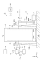
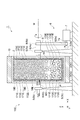
- FIG. 2 is a schematic view (front view) showing an example of an apparatus for producing tetrahydroborate.
- FIG. 3 is a schematic view (side view) showing an example of an apparatus for producing tetrahydroborate.
- the manufacturing apparatus 1 shown in FIGS. 2 and 3 is an apparatus capable of performing a pulverizing process by a ball mill and a plasma process in the same container.
- the manufacturing apparatus 1 has a ball mill container 2.
- the ball mill container 2 has therein a processing chamber containing a grinding media and a borate.
- the processing chamber is a sealable space in which the pulverization processing and the plasma processing are performed.
- the processing chamber is opened when the grinding media and borate are stored. Details of the processing chamber will be described later.
- the ball mill container 2 is, for example, a cylindrical heat-resistant and pressure-resistant container.
- the material of the ball mill vessel 2 does not affect the hydrogenation reaction of borate, and can be a metal material (steel material) that is less affected by hydrogen embrittlement.
- the ball mill container 2 is rotatably supported via the gantry 3a, 3b.
- the ball mill shafts 4a, 4b are connected to the respective center portions of both end faces 2a, 2b of the ball mill container 2.
- the ball mill shafts 4a and 4b are respectively provided along a rotation axis M extending in the X direction in the drawing.
- the ball mill shafts 4a, 4b are rotatably supported by bearings 5a, 5b supported by the gantry 3a, 3b, respectively.
- the manufacturing apparatus 1 includes a driving unit 6 for rotating the ball mill container 2.
- the driving unit 6 crushes borate by rotating the ball mill container 2.
- the drive unit 6 includes a motor 7, pulleys 8a and 8b, and a drive belt 9.
- the motor 7 is a drive source and has a motor shaft 7a that is a rotary drive shaft.
- the pulley 8a is provided on the motor shaft 7a, and the pulley 8b is provided on the ball mill shaft 4a.
- the drive belt 9 is hung on the outer periphery of the pulleys 8a and 8b.
- the rotational force of the motor shaft 7a is transmitted to the ball mill shaft 4a via the drive belt 9.
- the ball mill container 2 connected to the ball mill shaft 4a rotates.
- the rotation of the ball mill container 2 generates a grinding force and an impact force by the grinding media.
- the borate is mechanochemically treated.
- a heater 10 is provided on the outer periphery of the ball mill container 2 with a gap.
- the heater 10 has a cylindrical shape, and the ball mill container 2 is disposed therein.
- the heater 10 is supported by a gantry 3c different from the gantry 3a, 3b that supports the ball mill container 2. Therefore, the ball mill container 2 rotates inside the stationary heater 10.
- the heater 10 is connected to a power supply (not shown) and heats the ball mill container 2 from the outside to adjust the temperature of the processing chamber.
- the manufacturing apparatus 1 includes an atmosphere adjusting unit 11 that adjusts the atmosphere (gas type, pressure) in the processing chamber.
- the atmosphere adjusting unit 11 has a gas supply unit 11a and a gas exhaust unit 11b.
- the gas supply unit 11a supplies the source gas to the processing chamber, and sets the processing chamber to an atmosphere of the source gas.
- the gas supply unit 11a is connected to a gas source (not shown) of the source gas, and supplies the source gas from the gas source to the processing chamber.
- the gas source is a source such as a hydrocarbon gas, a hydrogen gas, and a hydrogen mixed gas.
- the gas exhaust unit 11b has a vacuum pump (not shown), and exhausts gas in the processing chamber to reduce the pressure in the processing chamber.
- the ball mill shaft 4b is hollow.
- a gas supply path 12 and a gas discharge path 13 are arranged inside the ball mill shaft 4b.
- the gas supply path 12 is provided inside the gas discharge path 13. That is, a double pipe is formed in which the gas supply path 12 is inside and the gas discharge path 13 is outside.
- the gas supply unit 11a supplies a source gas to the processing chamber via the gas supply path 12.
- the gas exhaust unit 11b adjusts the pressure of the processing chamber via the gas exhaust path 13.
- the gas exhaust unit 11b and the gas supply unit 11a are connected via a cooling condenser 11c.
- the cooling condenser 11c separates a raw material gas and moisture from the exhausted gas.
- the gas exhausted by the gas exhaust unit 11b is separated into raw material gas and moisture by the cooling condenser 11c, and only the raw material gas is returned to the gas supply unit 11a.
- the source gas is circulated.
- the ball mill vessel 2 is provided with a plasma generator for generating hydrogen plasma.
- the plasma generator generates a hydrogen plasma when a voltage is applied from the power supply 14.
- the plasma generation unit is provided in various modes as described below.
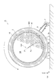
- FIG. 4 is a sectional view taken along the line AA of FIG. 3 showing the manufacturing apparatus having the first plasma generation unit.
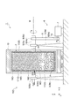
- FIG. 5 is a sectional view taken along the line BB of FIG. 2 showing the manufacturing apparatus having the first plasma generation unit.
- a processing chamber 2 d is defined inside the ball mill container 2. In the processing chamber 2d, the grinding media MD and the borate W are stored.
- the first plasma generation unit 15 includes a dielectric member 16, a pair of electrodes 17, and an insulator 18.
- the first plasma generation unit 15 is laminated on the inner wall of the ball mill container 2 in the order of the insulator 18, the pair of electrodes 17, and the dielectric member 16, and is configured as a laminate.
- the insulator 18 is provided on the inner wall of the circumferentially curved surface of the ball mill container 2.
- the insulator 18 may be provided on the entire inner wall of the ball mill container 2.
- the insulator 18 insulates between the pair of electrodes 17.
- the insulator 18 also electrically insulates between the pair of electrodes 17 and the ball mill container 2.
- the material of the insulator 18 is, for example, polyimide or ultra-high molecular weight polyethylene.
- the pair of electrodes 17 is connected to the dielectric member 16, and a voltage is applied from the power supply 14 (FIG. 1).
- the pair of electrodes 17 are provided so as to be in contact with the dielectric member 16.
- the power supply 14 is a variable power supply that can change the frequency of the supply voltage from 1 to 50 kHz as an example.
- the power supply 14 supplies a voltage having an optimum frequency based on the amount of the contents, the state of the source gas, and the like.
- the power supply 14 is electrically connected to the pair of electrodes 17 via a slip ring (not shown) provided on the ball mill shaft 4a.
- the pair of electrodes 17 includes a first electrode 171 and a second electrode 172 and is provided on the surface of the insulator 18.
- the first electrode 171 and the second electrode 172 are arranged apart from each other and are arranged so as not to directly conduct.
- a plurality of pairs of electrodes 17 can be arranged on the circumference of the ball mill container 2.
- the first electrode 171 and the second electrode 172 are arranged at equal intervals on the circumference of the ball mill container 2.
- the first electrode 171 and the second electrode 172 each have a comb shape, and are arranged so that the comb teeth are symmetrically combined.
- the material of the pair of electrodes 17 is a metal having electrical conductivity or the like, and examples thereof include copper, brass, iron, and aluminum.
- the pair of electrodes 17 may be at least a pair of electrodes.
- the pair of electrodes 17 may be a three-to-one pair of electrodes as a three-phase electrode.
- the first plasma generation unit 15 generates the hydrogen plasma P on the surface of the dielectric member 16 by dielectric barrier discharge based on the voltage applied from the power supply 14 in the processing chamber 2d in the atmosphere of the source gas. Thereby, the first plasma generation unit 15 exposes the borate W to the hydrogen plasma P during the rotation of the ball mill container 2.
- FIG. 6 is a sectional view taken along the line AA of FIG. 3 showing the manufacturing apparatus having the second plasma generating unit.
- FIG. 7 is a sectional view taken along the line BB of FIG. 2 showing the manufacturing apparatus having the second plasma generation unit.
- a processing chamber 2 d is defined inside the ball mill container 2. In the processing chamber 2d, the grinding media MD and the borate W are stored.
- the second plasma generation unit 15A is configured to be able to generate a plasma jet of hydrogen plasma when a voltage is applied.
- the second plasma generation unit 15 ⁇ / b> A has a hollow pipe-shaped main body 20 and a plasma jet nozzle 21.
- the main body 20 has electrodes (not shown) in its internal space.
- the material of the electrode is a metal or the like having electrical conductivity, and examples thereof include copper, brass, iron, and aluminum.
- a source gas is supplied from the gas supply unit 11 a (FIG. 1) to the internal space of the main body 20 via the gas supply path 12.
- a voltage is applied to the electrodes of the main body 20 from the power supply 14 (FIG. 1).
- the power supply 14 is a variable power supply that can change the frequency of the supply voltage from 1 to 50 kHz as an example.
- the power supply 14 supplies a voltage having an optimum frequency based on the amount of the contents, the state of the source gas, and the like.
- the power supply 14 is electrically connected to an electrode of the plasma jet nozzle 21 via a slip ring (not shown) provided on the ball mill shaft 4a.
- the material of the main body 20 is, for example, a dielectric (for example, high-purity alumina). In the main body 20, a plasma jet is generated based on the voltage applied from the power supply 14 and the source gas supplied from the gas supply unit 11a.
- the plasma jet nozzle 21 is provided at the tip of the main body 20.
- the plasma jet nozzle 21 is disposed on the central axis of the processing chamber 2d of the ball mill container 2.
- the plasma jet nozzle 21 has a hollow pipe shape, and has an intermittent hole provided linearly in the pipe length direction.
- a plasma jet PJ of hydrogen plasma is ejected from the intermittent hole.
- the plasma jet nozzle 21 is fixedly disposed in the processing chamber 2d so as to jet a plasma jet to the stagnation portion of the grinding media MD and the borate W accommodated in the processing chamber 2d.
- the ejection angle of the plasma jet nozzle 21 is set so as to be ejected near the lower part of the processing chamber 2d where the kinetic energy of the grinding media MD is the largest.
- the material of the plasma jet nozzle 21 is, for example, a dielectric material (for example, high-purity alumina).
- the plasma jet nozzle 21 may come into direct contact with the grinding media MD. For this reason, the amount of the grinding media MD and the rotation speed of the ball mill container 2 may be adjusted so that the grinding media MD does not pass through the center of the processing chamber 2d.
- the second plasma generation unit 15A generates a plasma jet PJ of hydrogen plasma based on the voltage applied from the power supply 14 in the processing chamber 2d. Thereby, the second plasma generation unit 15A exposes the borate W to hydrogen plasma during rotation of the ball mill container 2.
- FIG. 8 is a sectional view taken along the line AA of FIG. 3 showing the manufacturing apparatus having the third plasma generation unit.
- FIG. 9 is a cross-sectional view taken along the line BB of FIG. 2 showing the manufacturing apparatus having the third plasma generation unit.
- a processing chamber 2 d is defined inside the ball mill container 2. In the processing chamber 2d, the grinding media MD and the borate W are stored.
- the third plasma generation unit 15B includes a pair of electrodes 17B and an insulator 18B.
- the third plasma generation unit 15B is laminated on the inner wall of the ball mill container 2 in the order of the insulator 18B and the pair of electrodes 17B, and is configured as a laminate.
- the insulator 18B is provided on the inner wall of the circumferentially curved surface of the ball mill container 2.
- the insulator 18B may be provided on the entire inner wall of the ball mill container 2.
- the insulator 18B insulates between the pair of electrodes 17B.
- the insulator 18B also electrically insulates between the pair of electrodes 17B and the ball mill container 2.
- the material of the insulator 18B is, for example, polyimide or ultra-high molecular weight polyethylene.
- the power supply 14 is, for example, a power supply that can supply a pulse voltage.
- the power supply 14 adjusts the duty ratio (interval between energization and non-energization) in a range of 1: 9 to 9: 1, for example, with a pulse voltage cycle of 10 ms per cycle.
- the power supply 14 supplies a pulse voltage having an optimum duty ratio based on the amount of the contents, the state of the source gas, and the like.
- the power supply 14 is electrically connected to the pair of electrodes 17B via a slip ring (not shown) provided on the ball mill shaft 4a.
- the pair of electrodes 17B includes a first electrode 171B and a second electrode 172B, and is provided on the surface of the insulator 18B.
- the first electrode 171B and the second electrode 172B are arranged apart from each other and are arranged so as not to directly conduct.
- a plurality of pairs of electrodes 17B can be arranged on the circumference of the ball mill container 2.
- the first electrode 171B and the second electrode 172B are arranged at equal intervals on the circumference of the ball mill container 2.
- the first electrode 171B and the second electrode 172B extend in the direction of the central axis of the ball mill container 2 (the direction orthogonal to the circumferential direction).
- the surfaces of the pair of electrodes 17B face the processing chamber 2d. That is, the pair of electrodes 17B constitute at least a part of the inner wall surface of the processing chamber 2d. In the examples of FIGS. 8 and 9, the pair of electrodes 17B constitute a part of the inner wall of the processing chamber 2d.
- the material of the pair of electrodes 17B is a metal having electrical conductivity or the like, and is, for example, copper, brass, iron, or aluminum.
- the pair of electrodes 17B may be at least a pair of electrodes.
- the pair of electrodes 17B may be a three-to-one pair of electrodes as a three-phase electrode.
- a lifter member (not shown) may be provided in the processing chamber 2d.
- the lifter member is a member for lifting the contents of the processing chamber 2d by rotating the container, and is, for example, a member standing upright from the inner wall of the processing chamber 2d toward the center.
- the pair of electrodes 17B may constitute at least a part of such a lifter member.
- At least the surface of the grinding media MD has electrical conductivity.
- the state of conduction between the pair of electrodes 17B changes.
- the crushed media MD flows, and the energization state between the pair of electrodes 17B changes one after another.
- the third plasma generating unit 15B applies a pulse voltage from the power supply 14 in the processing chamber 2d in the atmosphere of the raw material gas, so that the spark-like hydrogen plasma P Generate Thereby, the third plasma generating unit 15B exposes the borate W to the hydrogen plasma P during the rotation of the ball mill container 2.
- FIG. 10 is a cross-sectional view taken along the line AA of FIG. 3 showing the manufacturing apparatus having the fourth plasma generation unit.
- FIG. 11 is a cross-sectional view taken along the line BB of FIG. 2 showing the manufacturing apparatus having the fourth plasma generation unit.
- a processing chamber 2 d is defined inside the ball mill container 2. In the processing chamber 2d, the grinding media MD and the borate W are stored.
- the fourth plasma generation unit 15C includes a pair of electrodes 17C and an insulator 18C.
- the fourth plasma generation unit 15C is laminated on the inner wall of the ball mill container 2 in the order of the insulator 18C and the pair of electrodes 17C, and is configured as a laminate.
- the fourth plasma generation unit 15C differs from the third plasma generation unit 15B in the extending direction of the pair of electrodes 17C, and the other configuration is the same.
- the first electrode 171C and the second electrode 172C extend along a direction (circumferential direction) orthogonal to the central axis of the ball mill container 2.
- the pair of electrodes 17C may be at least a pair of electrodes.
- the pair of electrodes 17C may be a three-to-one pair of electrodes as a three-phase electrode.
- the fourth plasma generation unit 15C applies a pulse voltage from the power supply 14 in the processing chamber 2d in the atmosphere of the raw material gas, so that the spark-like hydrogen plasma P Generate Thereby, the fourth plasma generating unit 15C exposes the borate W to the hydrogen plasma P during the rotation of the ball mill container 2.
- FIG. 12 is a cross-sectional view taken along the line AA of FIG. 3 showing the manufacturing apparatus having the fifth plasma generation unit.
- FIG. 13 is a sectional view taken along the line BB of FIG. 2 showing the manufacturing apparatus having the fifth plasma generation unit.
- a processing chamber 2 d is defined inside the ball mill container 2. In the processing chamber 2d, the grinding media MD and the borate W are stored.
- the fifth plasma generation unit 15D includes a pair of electrodes 17D and an insulator 18D.
- the fifth plasma generation unit 15D is laminated on the inner wall of the ball mill container 2 in the order of the insulator 18D and the pair of electrodes 17D, and is configured as a laminate.
- the fifth plasma generator 15D differs from the third plasma generator 15B in the location of the insulator 18D and the pair of electrodes 17C, and has the same other configuration.
- the insulator 18D is disposed on both inner walls of both ends and the circumferential surface of the processing chamber 2d.
- the insulator 18D may be arranged only on the inner walls at both end surfaces of the processing chamber 2d.
- the first electrode 171D and the second electrode 172D are annularly arranged on the inner walls at both end surfaces of the processing chamber 2d so as to surround the rotation axis of the ball mill container 2.
- the first electrodes 171D and the second electrodes 172D are alternately arranged along the rotation direction.
- the pair of electrodes 17D may be at least a pair of electrodes.
- the pair of electrodes 17D may be a three-to-one pair of electrodes as a three-phase electrode.
- the fifth plasma generation unit 15D applies a pulse voltage from the power supply 14 in the processing chamber 2d in the atmosphere of the raw material gas, so that the spark-like hydrogen plasma P Generate Thereby, the fifth plasma generating unit 15D exposes the borate W to the hydrogen plasma P during the rotation of the ball mill container 2.
- FIG. 14 is a cross-sectional view taken along the line AA of FIG. 3 showing the manufacturing apparatus having the sixth plasma generation unit.
- FIG. 15 is a sectional view taken along the line BB of FIG. 2 showing the manufacturing apparatus having the sixth plasma generating unit.
- a processing chamber 2 d is defined inside the ball mill container 2. In the processing chamber 2d, the grinding media MD and the borate W are stored.
- the sixth plasma generation unit 15E includes a pair of electrodes 17E and an insulator 18E.
- the sixth plasma generation unit 15E is laminated on the inner wall of the ball mill container 2 in the order of the insulator 18E and the pair of electrodes 17E, and is configured as a laminate.
- the sixth plasma generation unit 15E is different from the fifth plasma generation unit 15D in the shape and arrangement of the pair of electrodes 17E, and is otherwise the same.
- the first electrode 171E and the second electrode 172E are concentrically arranged on the inner walls at both end surfaces of the processing chamber 2d so as to surround the rotation axis of the ball mill container 2.
- the first electrodes 171E and the second electrodes 172E are alternately arranged along the radial direction.
- the pair of electrodes 17E may be at least a pair of electrodes.
- the pair of electrodes 17E may be a three-to-one pair of electrodes as three-phase electrodes.
- the sixth plasma generation unit 15E applies a pulse voltage from the power supply 14 in the processing chamber 2d in the atmosphere of the raw material gas, so that the spark-like hydrogen plasma P Generate Thereby, the sixth plasma generating unit 15E exposes the borate W to the hydrogen plasma P during the rotation of the ball mill container 2.
- the manufacturing apparatus 1 can employ any one of the above-described first to sixth plasma generation units 15 to 15E.
- the manufacturing apparatus 1 includes a control unit 100 (FIG. 2) that controls the above-described apparatus components.
- the control unit 100 is, for example, a computer including a processor, a storage unit, an input device, a display device, and the like.
- the storage unit of the control unit 100 stores a computer program for executing the method MT and various data used for executing the method MT in a readable state.
- the control unit 100 operates according to a program based on the input recipe and sends out a control signal.
- Each component of the manufacturing apparatus 1 is controlled by a control signal from the control unit 100.
- Each step of the method MT can be executed by operating each component of the manufacturing apparatus 1 under the control of the control unit 100.
- Example 1 Using the production apparatus 1 shown in FIGS. 1 to 5, tetrahydroborate was produced.
- NaBO 2 .4H 2 O sodium metaborate tetrahydrate: manufactured by Kishida Chemical Co., Ltd., content 98% by mass
- the average particle size of the granular NaBO 2 was 100 ⁇ m. The average particle size was measured with a digital microscope.
- the power of the motor 7 was turned on, and the rotation of the ball mill container 2 was started. While the ball mill container 2 was rotating, the inside of the ball mill container 2 was heated to 300 ° C., and hydrogen was circulated and injected so that the pressure inside the ball mill container 2 became atmospheric pressure. The atmosphere in the ball mill container 2 taken out by the circulation flow was treated by a cooling condenser to separate water and hydrogen, and then hydrogen was injected into the ball mill container 2 again. The rotation of the ball mill container 2 was continued until the time product E (kJs / kg) of the grinding energy per unit weight of the object to be treated reached a predetermined value.
- the hydrogenation rate (conversion rate) was calculated as follows. First, sodium tetrahydroborate contained in the treated object was hydrolyzed, and the amount of hydrogen generated thereby was quantified. The amount of hydrogen was measured by measuring the volume of gas produced and diluting the gas 200 times with air using a hydrogen detector tube (manufactured by Komei Rika Kogyo Co., Ltd., measurement concentration range: 0.05 to 0.8%). It was calculated from the obtained hydrogen concentration. Then, the hydrogenation rate was calculated from the amount of hydrogen determined as described above, based on the amount of hydrogen at the time of 100% conversion.
- the crystal structure of the sample after the plasma treatment was analyzed by XRD.
- the obtained sample contained sodium tetrahydroborate having a composition of Na 0.6 B 0.9 H 4.0 .
- Tetrahydroborate was produced using the production apparatus 1 shown in FIGS. 1, 2, 3, 6, and 7.
- NaBO 2 .4H 2 O sodium metaborate tetrahydrate: manufactured by Kishida Chemical Co., Ltd., content 98% by mass
- This was heated at 160 ° C. for 15 minutes while being pulverized with a ball mill to remove water of crystallization to obtain granular NaBO 2 (anhydrous sodium metaborate).
- the average particle size of the granular NaBO 2 was 100 ⁇ m. The average particle size was measured with a digital microscope.
- the power of the motor 7 was turned on, and the rotation of the ball mill container 2 was started. While the ball mill container 2 was rotating, the inside of the ball mill container 2 was heated to 300 ° C., and hydrogen was circulated and injected so that the pressure inside the ball mill container 2 became atmospheric pressure. The atmosphere in the ball mill container 2 taken out by the circulation flow was treated by a cooling condenser to separate water and hydrogen, and then hydrogen was injected into the ball mill container 2 again. The rotation of the ball mill container 2 was continued until the time product E (kJs / kg) of the grinding energy per unit weight of the object to be treated reached a predetermined value.
- the hydrogenation rate (conversion rate) was calculated as follows. First, sodium tetrahydroborate contained in the treated object was hydrolyzed, and the amount of hydrogen generated thereby was quantified. The amount of hydrogen was measured by measuring the volume of gas produced and diluting the gas 200 times with air using a hydrogen detector tube (manufactured by Komei Rika Kogyo Co., Ltd., measurement concentration range: 0.05 to 0.8%). It was calculated from the obtained hydrogen concentration. Then, the hydrogenation rate was calculated from the amount of hydrogen determined as described above, based on the amount of hydrogen at the time of 100% conversion.
- the crystal structure of the sample after the plasma treatment was analyzed by XRD.
- the obtained sample contained sodium tetrahydroborate having a composition of Na 0.6 B 0.9 H 4.0 .
- Tetrahydroborate was produced using the production apparatus 1 shown in FIGS. 1, 2, 3, 8, and 9.
- NaBO 2 .4H 2 O sodium metaborate tetrahydrate: manufactured by Kishida Chemical Co., Ltd., content 98% by mass
- This was heated at 160 ° C. for 15 minutes while being pulverized with a ball mill to remove water of crystallization to obtain granular NaBO 2 (anhydrous sodium metaborate).
- the average particle size of the granular NaBO 2 was 100 ⁇ m. The average particle size was measured with a digital microscope.
- the power of the motor 7 was turned on, and the rotation of the ball mill container 2 was started. While the ball mill container 2 was rotating, the inside of the ball mill container 2 was heated to 300 ° C., and hydrogen was circulated and injected so that the pressure inside the ball mill container 2 became atmospheric pressure. The atmosphere in the ball mill container 2 taken out by the circulation flow was treated by a cooling condenser to separate water and hydrogen, and then hydrogen was injected into the ball mill container 2 again. The rotation of the ball mill container 2 was continued until the time product E (kJ ⁇ s / kg) of the grinding energy per unit weight of the object to be treated reached a predetermined value.
- a 3.3-ms pulsating DC voltage obtained by full-wave rectifying a three-phase alternating current between a pair of electrodes 17B provided on the inner wall of the ball mill container 2.
- a pulse voltage of 5 V was applied to turn on and off at a ratio of 8% for energizing and 2% for non-energizing.
- Spark-like high-temperature hydrogen plasma was generated between the pulverizing media at the time of collision with the pulverizing media (chrome steel balls having an average diameter of 30 mm) flowing inside the reaction vessel or at the collision point when the inner wall of the reaction vessel collided with the pulverizing media.
- the hydrogen plasma generation was continued while the rotation of the ball mill container 2 was continued.
- the hydrogenation rate (conversion rate) was calculated as follows. First, sodium tetrahydroborate contained in the treated object was hydrolyzed, and the amount of hydrogen generated thereby was quantified. The amount of hydrogen was measured by measuring the volume of gas produced and diluting the gas 200 times with air using a hydrogen detector tube (manufactured by Komei Rika Kogyo Co., Ltd., measurement concentration range: 0.05 to 0.8%). It was calculated from the obtained hydrogen concentration. Then, the hydrogenation rate was calculated from the hydrogen amount determined as described above based on the hydrogen amount at the time of 100% conversion.
- the crystal structure of the sample after the plasma treatment was analyzed by XRD.
- the obtained sample contained sodium tetrahydroborate having a composition of Na 0.6 B 0.9 H 4.0 .
- Example 4 The production of tetrahydroborate was carried out using the production apparatus 1 shown in FIGS. 1, 2, 3, 10, and 11.
- NaBO 2 .4H 2 O sodium metaborate tetrahydrate: manufactured by Kishida Chemical Co., Ltd., content 98% by mass
- the average particle size of the granular NaBO 2 was 100 ⁇ m. The average particle size was measured with a digital microscope.
- the power of the motor 7 was turned on, and the rotation of the ball mill container 2 was started. While the ball mill container 2 was rotating, the inside of the ball mill container 2 was heated to 300 ° C., and hydrogen was circulated and injected so that the pressure inside the ball mill container 2 became atmospheric pressure. The atmosphere in the ball mill container 2 taken out by the circulation flow was treated by a cooling condenser to separate water and hydrogen, and then hydrogen was injected into the ball mill container 2 again. The rotation of the ball mill container 2 was continued until the time product E (kJs / kg) of the grinding energy per unit weight of the object to be treated reached a predetermined value.
- a 3.3-ms pulsating DC voltage obtained by full-wave rectifying a three-phase alternating current between a pair of electrodes 17C provided on the inner wall of the ball mill container 2.
- a pulse voltage of 5 V was applied to turn on and off at a ratio of 8% for energizing and 2% for non-energizing.
- Spark-like high-temperature hydrogen plasma was generated between the pulverization media at the time of collision with the pulverization media (chrome steel balls having an average diameter of 30 mm) flowing in the reaction vessel or at the collision location when the pulverization media collided with the inner wall of the reaction vessel.
- the hydrogen plasma generation was continued while the rotation of the ball mill container 2 was continued.
- the hydrogenation rate (conversion rate) was calculated as follows. First, sodium tetrahydroborate contained in the treated object was hydrolyzed, and the amount of hydrogen generated thereby was quantified. The amount of hydrogen was measured by measuring the volume of gas produced and diluting the gas 200 times with air using a hydrogen detector tube (manufactured by Komei Rika Kogyo Co., Ltd., measurement concentration range: 0.05 to 0.8%). It was calculated from the obtained hydrogen concentration. Then, the hydrogenation rate was calculated from the amount of hydrogen determined as described above, based on the amount of hydrogen at the time of 100% conversion.
- the crystal structure of the sample after the plasma treatment was analyzed by XRD.
- the obtained sample contained sodium tetrahydroborate having a composition of Na 0.6 B 0.9 H 4.0 .
- Example 5 Using the production apparatus 1 shown in FIGS. 1, 2, 3, 12, and 13, tetrahydroborate was produced.
- NaBO 2 .4H 2 O sodium metaborate tetrahydrate: manufactured by Kishida Chemical Co., Ltd., content 98% by mass
- the average particle size of the granular NaBO 2 was 100 ⁇ m. The average particle size was measured with a digital microscope.
- the power of the motor 7 was turned on, and the rotation of the ball mill container 2 was started. While the ball mill container 2 was rotating, the inside of the ball mill container 2 was heated to 300 ° C., and hydrogen was circulated and injected so that the pressure inside the ball mill container 2 became atmospheric pressure. The atmosphere in the ball mill container 2 taken out by the circulation flow was treated by a cooling condenser to separate water and hydrogen, and then hydrogen was injected into the ball mill container 2 again. The rotation of the ball mill container 2 was continued until the time product E (kJs / kg) of the grinding energy per unit weight of the object to be treated reached a predetermined value.
- the pulsating DC voltage obtained by full-wave rectification of the three-phase alternating current between the pair of electrodes 17D provided on the inner wall of the ball mill container 2 is 3.3 ms.
- a pulse voltage of 5 V was applied to turn ON / OFF at a ratio of 8% for energizing and 8% for non-energizing.
- Spark-like high-temperature hydrogen plasma was generated between the pulverization media at the time of collision with the pulverization media (chrome steel balls having an average diameter of 30 mm) flowing in the reaction vessel or at the collision location when the pulverization media collided with the inner wall of the reaction vessel.
- the hydrogen plasma generation was continued while the rotation of the ball mill container 2 was continued.
- the hydrogenation rate (conversion rate) was calculated as follows. First, sodium tetrahydroborate contained in the treated object was hydrolyzed, and the amount of hydrogen generated thereby was quantified. The amount of hydrogen was measured by measuring the volume of gas produced and diluting the gas 200 times with air using a hydrogen detector tube (manufactured by Komei Rika Kogyo Co., Ltd., measurement concentration range: 0.05 to 0.8%). It was calculated from the hydrogen concentration obtained. Then, the hydrogenation rate was calculated from the amount of hydrogen determined as described above, based on the amount of hydrogen at the time of 100% conversion.
- the crystal structure of the sample after the plasma treatment was analyzed by XRD.
- the obtained sample contained sodium tetrahydroborate having a composition of Na 0.6 B 0.9 H 4.0 .
- Example 6 The production of tetrahydroborate was performed using the production apparatus 1 shown in FIGS. 1, 2, 3, 14, and 15.
- NaBO 2 .4H 2 O sodium metaborate tetrahydrate: manufactured by Kishida Chemical Co., Ltd., content 98% by mass
- the average particle size of the granular NaBO 2 was 100 ⁇ m. The average particle size was measured with a digital microscope.
- the power of the motor 7 was turned on, and the rotation of the ball mill container 2 was started. While the ball mill container 2 was rotating, the inside of the ball mill container 2 was heated to 300 ° C., and hydrogen was circulated and injected so that the pressure inside the ball mill container 2 became atmospheric pressure. The atmosphere in the ball mill container 2 taken out by the circulation flow was treated by a cooling condenser to separate water and hydrogen, and then hydrogen was injected into the ball mill container 2 again. The rotation of the ball mill container 2 was continued until the time product E (kJ ⁇ s / kg) of the grinding energy per unit weight of the object to be treated reached a predetermined value.
- a 3.3-ms pulsating DC voltage obtained by full-wave rectifying a three-phase alternating current between a pair of electrodes 17E provided on the inner wall of the ball mill container 2.
- a pulse voltage of 5 V was applied to turn on and off at a ratio of 8% for energizing and 2% for non-energizing.
- Spark-like high-temperature hydrogen plasma was generated between the pulverization media at the time of collision with the pulverization media (chrome steel balls having an average diameter of 30 mm) flowing in the reaction vessel or at the collision location when the pulverization media collided with the inner wall of the reaction vessel.
- the hydrogen plasma generation was continued while the rotation of the ball mill container 2 was continued.
- the hydrogenation rate (conversion rate) was calculated as follows. First, sodium tetrahydroborate contained in the treated object was hydrolyzed, and the amount of hydrogen generated thereby was quantified. The amount of hydrogen was measured by measuring the volume of gas produced and diluting the gas 200 times with air using a hydrogen detector tube (manufactured by Komei Rika Kogyo Co., Ltd., measurement concentration range: 0.05 to 0.8%). It was calculated from the obtained hydrogen concentration. Then, the hydrogenation rate was calculated from the hydrogen amount determined as described above based on the hydrogen amount at the time of 100% conversion.
- the crystal structure of the sample after the plasma treatment was analyzed by XRD.
- the obtained sample contained sodium tetrahydroborate having a composition of Na 0.6 B 0.9 H 4.0 .
Landscapes
- Physics & Mathematics (AREA)
- Engineering & Computer Science (AREA)
- Plasma & Fusion (AREA)
- Chemical & Material Sciences (AREA)
- Organic Chemistry (AREA)
- Life Sciences & Earth Sciences (AREA)
- General Life Sciences & Earth Sciences (AREA)
- Geology (AREA)
- Inorganic Chemistry (AREA)
- Spectroscopy & Molecular Physics (AREA)
- Analytical Chemistry (AREA)
- Plasma Technology (AREA)
Abstract
テトラヒドロほう酸塩の製造方法は、ほう酸塩を粉砕しつつ水素プラズマにさらす水素化処理工程(ステップS14)を備える。
Description
本開示は、テトラヒドロほう酸塩の製造方法、テトラヒドロほう酸塩の製造装置及びテトラヒドロほう酸塩に関する。
特許文献1,2は、ほう酸塩を水素化することによりテトラヒドロほう酸塩を製造する方法を開示する。特許文献1開示の方法では、約550℃、2.3 MPaの水素雰囲気下で、メタほう酸ナトリウム粉末とマグネシウム粉末とを2時間程度反応させる。特許文献2開示の方法では、約300℃、1 MPaの水素雰囲気下で、メタほう酸ナトリウム粉末と粒状アルミニウムとを、粒状アルミニウムを圧延粉砕しながら1時間程度反応させる。
特許文献1,2に開示された方法においては、大容積反応容器内の雰囲気を1時間以上にわたって高温高圧に保つ必要があるため、外部から大量のエネルギーを投入し続ける必要がある。また、特許文献1,2に開示された方法は、還元金属としてマグネシウムやアルミニウムを消耗材として消費するため、非常に高コストなプロセスを含む。さらには、特許文献1,2に開示された方法は、1バッチの処理時間に1時間以上を要するため、生産性が上がらない。このように、テトラヒドロほう酸塩の製造分野においては、産業応用の観点から満足のいく製造方法が確立されていないのが現状である。
本開示は、上記事情に鑑みてなされたものであり、テトラヒドロほう酸塩の新規な製造方法を提供する。本開示はまた、当該製造方法に用いられる製造装置、及び当該製造方法により得られるテトラヒドロほう酸塩を提供する。
本開示の一側面は、ほう酸塩を粉砕しつつ水素プラズマにさらす水素化処理工程を備えるテトラヒドロほう酸塩の製造方法である。
一実施形態においては、水素プラズマは、水素ガス及び炭化水素ガスの少なくとも一種を含む原料ガスを用いて生成されてもよい。
一実施形態においては、水素プラズマは、誘電体バリア放電で得られたプラズマでもよい。一実施形態においては、水素プラズマは、プラズマジェットとしてほう酸塩に提供されてもよい。一実施形態においては、水素プラズマは高温プラズマでもよい。
一実施形態においては、水素化処理工程では、ほう酸塩を加熱しながら粉砕しつつ水素プラズマにさらしてもよい。
一実施形態においては、水素化処理工程において、水素と結合し得る還元材をほう酸塩とともに同時に処理してもよい。
一実施形態においては、ほう酸塩はメタほう酸ナトリウムでもよい。
一実施形態においては、製造方法は、水素化処理工程の前に、ほう酸塩を加熱する予備加熱工程をさらに備えてもよい。
一実施形態においては、製造方法は、水素化処理工程の前に、テトラヒドロほう酸塩と水とを反応させてほう酸塩を得るほう酸塩調製工程をさらに備えてもよい。
一実施形態においては、製造方法は、予備加熱工程の前に、テトラヒドロほう酸塩と水とを反応させてほう酸塩を得るほう酸塩調製工程をさらに備えてもよい。
本開示の他の一側面は、テトラヒドロほう酸塩の製造装置である。装置は、粉砕メディア及びほう酸塩を収容する処理室を内部に有するボールミル容器と、ボールミル容器を回転させる駆動部と、処理室へ原料ガスを供給するガス供給部と、電圧を印加する電源と、処理室の内壁面の少なくとも一部を構成する誘電体部材と、誘電体部材に接続され、電源から電圧が印加される少なくとも一対の電極と、少なくとも一対の電極間を絶縁する絶縁体とを有するプラズマ生成部と、を備え、駆動部は、ボールミル容器を回転させることによりほう酸塩を粉砕し、ガス供給部は、処理室を原料ガスの雰囲気とし、プラズマ生成部は、原料ガスの雰囲気中の処理室にて電源から印加された電圧に基づいた誘電体バリア放電により誘電体部材の表面に水素プラズマを生成し、ボールミル容器の回転中においてほう酸塩を水素プラズマにさらす。
本開示の他の一側面は、テトラヒドロほう酸塩の製造装置である。装置は、粉砕メディア及びほう酸塩を収容する処理室を内部に有するボールミル容器と、ボールミル容器を回転させる駆動部と、電圧が印加されることで水素プラズマのプラズマジェットを生成可能であり、処理室に収容された粉砕メディア及びほう酸塩の滞留箇所へプラズマジェットを噴射するように処理室に固定配置されるプラズマジェットノズルを有するプラズマ生成部と、プラズマ生成部へ電圧を印加する電源と、プラズマ生成部へ原料ガスを供給するガス供給部と、を備え、駆動部は、ボールミル容器を回転させることによりほう酸塩を粉砕し、プラズマジェットノズルは、電源から印加された電圧及びガス供給部から供給された原料ガスに基づいてプラズマジェットを生成し、ボールミル容器の回転中において粉砕メディア及びほう酸塩の滞留箇所へプラズマジェットを噴射する。
本開示の他の一側面は、テトラヒドロほう酸塩の製造装置である。装置は、電気伝導性を有する粉砕メディア及びほう酸塩を収容する処理室を内部に有するボールミル容器と、ボールミル容器を回転させる駆動部と、処理室へ原料ガスを供給するガス供給部と、処理室の内壁面の少なくとも一部、又は、処理室に設けられたリフタ部材の少なくとも一部を構成する少なくとも一対の電極と、少なくとも一対の電極間を絶縁する絶縁体とを有するプラズマ生成部と、少なくとも一対の電極間に電圧を印加する電源と、を備え、駆動部は、ボールミル容器を回転させることにより、ほう酸塩を粉砕し、かつ、流動させた粉砕メディアを介して少なくとも一対の電極間の通電状態を変化させ、ガス供給部は、処理室を原料ガスの雰囲気とし、プラズマ生成部は、原料ガスの雰囲気中の処理室にて電源から電圧が印加されることにより、ボールミル容器の回転中において粉砕メディアの表面にスパーク状の水素プラズマを生成し、ほう酸塩を水素プラズマにさらす。
本開示の他の一側面は、下記一般式(A)又は(B)で表される組成を有するテトラヒドロほう酸塩である。
MxByHz (A)
NsBtHu (B)
式(A)中、MはLi、Na及びKからなる群より選択される少なくとも一種であり、xは0.05以上1.0未満であり、yは0.6以上1.0未満であり、zは4.0である。式(B)中、NはCa及びMgからなる群より選択される少なくとも一種であり、sは0.05以上1.0未満であり、tは1.2以上2.0未満であり、uは8.0である。
MxByHz (A)
NsBtHu (B)
式(A)中、MはLi、Na及びKからなる群より選択される少なくとも一種であり、xは0.05以上1.0未満であり、yは0.6以上1.0未満であり、zは4.0である。式(B)中、NはCa及びMgからなる群より選択される少なくとも一種であり、sは0.05以上1.0未満であり、tは1.2以上2.0未満であり、uは8.0である。
本開示の種々の側面及び実施形態によれば、テトラヒドロほう酸塩の新規な製造方法を提供することができる。本開示の種々の側面及び実施形態によれば、テトラヒドロほう酸塩の製造装置を提供することができる。本開示の種々の側面及び実施形態によれば、当該製造方法により得られるテトラヒドロほう酸塩を提供することができる。
以下、場合により図面を参照しつつ本開示の実施形態について詳細に説明する。ただし、本開示は以下の実施形態に限定されるものではない。図中のX方向及びY方向が水平方向であり、Z方向が垂直方向である。
<テトラヒドロほう酸塩の製造方法>
図1は、テトラヒドロほう酸塩の製造方法の一例を示すフローチャートである。図1に示される方法MTは、ほう酸塩を原料としてテトラヒドロほう酸塩を製造する方法である。方法MTは、ほう酸塩調整工程(ステップS10)、予備加熱工程(ステップS12)、及び、水素化処理工程(ステップS14)を有する。
図1は、テトラヒドロほう酸塩の製造方法の一例を示すフローチャートである。図1に示される方法MTは、ほう酸塩を原料としてテトラヒドロほう酸塩を製造する方法である。方法MTは、ほう酸塩調整工程(ステップS10)、予備加熱工程(ステップS12)、及び、水素化処理工程(ステップS14)を有する。
方法MTにおいて、ほう酸塩調整工程(ステップS10)及び予備加熱工程(ステップS12)は、必ずしも実行する必要はなく、必要に応じて実行される。このため、最初に水素化処理工程(ステップS14)を説明し、次に、ほう酸塩調整工程(ステップS10)及び予備加熱工程(ステップS12)を説明する。
(水素化処理工程:ステップS14)
水素化処理工程は、ほう酸塩を粉砕しつつ水素プラズマにさらす工程である。ほう酸塩は、例えば、メタほう酸塩、四ほう酸塩、又は、五ほう酸塩である。メタほう酸塩は、一例として、NaBO2、KBO2、LiBO2、Ca(BO2)2、又は、Mg(BO2)2である。四ほう酸塩は、一例として、Na2B4O7、Na2O・2BO3、K2O・B2O3、Li2B4O7、又は、Mg3B4O9である。五ほう酸塩は、一例として、NaB5O8、Na2O・5B2O3、KB5O8、K2O・5B2O9、又は、LiB5O8である。ほう酸塩は、天然のほう酸塩鉱物であるNa2B4O7・10H2O、Na2B4O7・4H2O、Ca2B6O11・5H2O、CaNaB5O9・6H2O、Mg7Cl2B17O30などとしてもよい。入手容易性、入手コスト、化学的安定性、水素脱着容易性、水素貯蔵密度などの観点から、ほう酸塩として上述した例の中からメタほう酸ナトリウム(NaBO2)を選択してもよい。
水素化処理工程は、ほう酸塩を粉砕しつつ水素プラズマにさらす工程である。ほう酸塩は、例えば、メタほう酸塩、四ほう酸塩、又は、五ほう酸塩である。メタほう酸塩は、一例として、NaBO2、KBO2、LiBO2、Ca(BO2)2、又は、Mg(BO2)2である。四ほう酸塩は、一例として、Na2B4O7、Na2O・2BO3、K2O・B2O3、Li2B4O7、又は、Mg3B4O9である。五ほう酸塩は、一例として、NaB5O8、Na2O・5B2O3、KB5O8、K2O・5B2O9、又は、LiB5O8である。ほう酸塩は、天然のほう酸塩鉱物であるNa2B4O7・10H2O、Na2B4O7・4H2O、Ca2B6O11・5H2O、CaNaB5O9・6H2O、Mg7Cl2B17O30などとしてもよい。入手容易性、入手コスト、化学的安定性、水素脱着容易性、水素貯蔵密度などの観点から、ほう酸塩として上述した例の中からメタほう酸ナトリウム(NaBO2)を選択してもよい。
ほう酸塩は固体であり、形状は特に限定されない。ほう酸塩は、粉末状としてもよい。粉末状のほう酸塩の平均粒子径は、500 μm以下とすることができる。粉末状のほう酸塩の平均粒子径は、100 μm以下であってもよい。粉末状のほう酸塩の平均粒子径の下限は、特に限定されないが、5 μmとすることができる。粉末状のほう酸塩を用いることにより、粉砕処理の処理時間が短縮され、後述するプラズマ処理の効率も向上する。
水素化処理工程では、ほう酸塩の粉砕処理が行われる。粉砕処理は、ほう酸塩を微細な粉末とする処理である。粉砕処理は、一例としてボールミルが用いられる。ボールミルにおいては、ほう酸塩と粉砕メディアとが同一容器内に収容され、粉砕メディアの衝突により、ほう酸塩が粉砕される。なお、本実施形態において、ボールミルとは広義のボールミル(粉体工学便覧第2版参照)を意味し、いわゆる転動ボールミル(ポットミル、チューブミル及びコニカルミル)、振動ボールミル(円振動型振動ミル、旋回型振動ミル及び遠心ミル)、並びに遊星ミルを含む概念である。
水素化処理工程においては、水素プラズマ処理として、粉砕処理中のほう酸塩を水素プラズマにさらす。水素プラズマは、極めて活性の高い水素ラジカル(Hラジカル)や水素イオンを含む。ほう酸塩が水素プラズマにさらされることにより、ほう酸塩が有する酸素原子の結合部が切断され、酸素原子が除去される。そして、酸素原子が結合していた電子対に水素原子が結合することで、ほう酸塩の水素化が行われる。例えば、ほう酸塩としてメタほう酸ナトリウムを用いた場合、本工程にて以下の反応(1)が生じると考えられる。
NaBO2+4H2→NaBH4+2H2O (1)
NaBO2+4H2→NaBH4+2H2O (1)
水素プラズマ処理に用いる水素プラズマは、水素(H)を構成元素として含有するガスを用いて生成される。例えば、水素プラズマは、水素ガス及び炭化水素ガスの少なくとも一種を含む原料ガスを用いて生成することができる。炭化水素ガスは、一例として、CH4ガス、C2H2ガス、又は、C6H6ガスである。炭化水素のように水素よりも酸化しやすい元素を含むガスを用いた場合、ほう酸塩の酸素原子の除去が促進される。これにより、テトラヒドロほう酸塩の製造速度の向上が見込まれる。水素プラズマは、NH3ガスなどを用いて生成されてもよい。
原料ガスは、一酸化炭素などのような水素よりも酸化し易い元素を含むガスを含んでもよい。この場合、炭化水素ガスを採用した場合と同様に、ほう酸塩の酸素原子の除去が促進される。これにより、テトラヒドロほう酸塩の製造速度の向上が見込まれる。
原料ガスは、アルゴンガス、ヘリウムガス、ネオンガスなどのような、水素との組み合わせにおいてペニング効果が生じるガスを含んでもよい。この場合、水素プラズマのプラズマ濃度を高く保つことができるとともに、水素プラズマを安定的かつ広範囲に発生させることができる。これにより、テトラヒドロほう酸塩の製造速度の向上が見込まれる。
水素プラズマ処理は、一例として、半導体プロセスなどに一般的に使用されるプラズマ生成装置を用いて実施することができる。ほう酸塩及び原料ガスが供給される処理容器は、例えば、10~150Pa程度に減圧される。圧力を上記範囲に制御することにより、プラズマ密度の高い水素プラズマを発生させることができる。
水素プラズマは、低周波プラズマ(1~100 kHzの変動電圧によって励起されたプラズマ)、マイクロ波プラズマ(マイクロ波によって励起されたプラズマ)及びRFプラズマ(RF(Radio Frequency)によって励起されたプラズマ)のいずれであってもよい。これらのプラズマは、パルス励起されたプラズマであってもよく、直流励起されたプラズマであってもよい。
低周波プラズマを励起させる変動電圧の周波数は、被処理物や粉砕メディアの量や状態及び処理容器の形状や大きさなどによって最適値が選択され得る。変動電圧は、一例として可変周波数電源などを用いて調整される。低周波プラズマは簡易な構成で実現することができるため、装置コスト及び運用コスト共に安価に抑えることができる。
マイクロ波プラズマの励起に用いられるマイクロ波の周波数は、例えば、産業上使用可能な周波数帯であり、かつ、プラズマ密度の高い熱非平衡な水素プラズマを生成可能な周波数帯である1GHz以上に設定され得る。熱的に非平衡なプラズマは、いわゆる低温プラズマである。一例として、周波数2.45 GHzのマイクロ波が用いられる。
マイクロ波プラズマを励起する際の電力は、300 W以上とすることができる。また、ほう酸塩をプラズマ処理する処理時間は、ほう酸塩の量やプラズマ密度にも依存するが、例えば1時間以下とすることができ、0.5時間以下としてもよい。
マイクロ波を用いてマイクロ波プラズマを励起する場合、プラズマ密度が高く広範囲の水素プラズマが発生する。このため、テトラヒドロほう酸塩の製造速度を速めることができる。
また、上述した反応(1)のとおり、ほう酸塩から解離した酸素原子が水素プラズマと反応して水が生成される。マイクロ波を用いてマイクロ波プラズマを励起する場合、反応(1)で生成された水をマイクロ波によって効果的に加熱蒸発あるいは電離させることができる。このため、製造されたテトラヒドロほう酸塩と水とが反応してほう酸塩に戻る逆反応を抑制することができる。これにより、テトラヒドロほう酸塩の製造速度を速めることができる。
RFプラズマの生成に用いられる励起周波数は、法規制の観点から日本国内では13.56 MHzが一般的であるが、これに限定されない。RFプラズマは産業界で広く用いられているプラズマであるため、装置コスト及び運用コスト共に安価に抑えることができる。RFプラズマにより広範囲の水素プラズマが発生するため、テトラヒドロほう酸塩の製造速度を速めることができる。
水素プラズマは、熱平衡プラズマであってもよい。これにより、水素プラズマのプラズマ密度及びイオン温度を高くすることができるので、ほう酸塩の酸素原子の結合部を切断して酸素原子を解離する効果が高くなる。これにより、テトラヒドロほう酸塩の製造速度を速めることができる。なお、熱平衡水素プラズマは、高温プラズマともいう。熱平衡プラズマを用いてほう酸塩を処理する場合、反応(1)で生成された水を高エネルギーにより効果的に蒸発あるいは電離させることができる。このため、製造されたテトラヒドロほう酸塩と水とが反応してほう酸塩に戻る逆反応を抑制することができる。これにより、テトラヒドロほう酸塩の製造速度を速めることができる。
低周波プラズマ及びRFプラズマは、誘電体バリア放電によって生成されたプラズマであってもよい。誘電体バリア放電では、少なくとも一対の電極間に配置された絶縁体(誘電体)を介して気体に交流電圧を印加して放電させる。
水素プラズマは、プラズマジェットとしてほう酸塩へ供給されてもよい。プラズマジェットは、プラズマをノズルから噴射することで実現し得る。
水素化処理工程では、ほう酸塩を加熱しながら粉砕しつつ水素プラズマにさらしてもよい。加熱温度は、一例として40~300℃とすることができる。ほう酸塩を加熱しながら粉砕しつつ水素プラズマにさらすことにより、反応(1)の逆反応を抑制することができる。なお、上記のとおりマイクロ波プラズマを用いる場合は、当該マイクロ波によって上述した逆反応の抑制効果を奏することができる。
水素化処理工程では、水素と結合し得る還元材をほう酸塩とともに同時に処理してもよい。例えば、ほう酸塩は、還元材と共に粉砕されつつ水素プラズマにさられる。水素と結合し得る還元材は、ほう酸塩から解離する酸素原子をトラップし、酸素原子と水素とが反応して水が生成されることを抑制する。このため、反応(1)の逆反応を抑制することができる。還元材の一例は、マグネシウム(マグネシウム系材料)、アルミニウム(アルミニウム系材料)、鉄(鉄系材料)などの還元金属粉末や、炭素粉末である。なお、還元材を用いた場合には、後工程として、テトラヒドロほう酸塩と還元材に由来する不純物(主に金属酸化物)とを分離する工程が必要となる場合もある。しかしながら、還元材の作用により水の生成が抑制されるため、結果として水素化処理工程の効率は向上される。
水素化処理工程では、吸湿材をほう酸塩とともに同時に処理してもよい。例えば、ほう酸塩は、吸湿材と共に粉砕されつつ水素プラズマにさらされる。吸湿材は、ほう酸塩から解離する酸素原子と水素プラズマとの反応によって生成される水分子をトラップする。このため、反応(1)の逆反応を抑制することができる。吸湿材の一例は、生石灰、シリカゲル、ベントナイト、塩化マグネシウム、塩化カルシウムなどである。吸湿材の作用により水の生成が抑制されるため、水素化処理工程の効率は向上される。
(予備加熱工程:ステップS12)
方法MTは、水素化処理工程前に、ほう酸塩を加熱する予備加熱工程をさらに備えてもよい。予備加熱工程は、ほう酸塩の種類や量に依存するが、例えば40~300℃にて0.1~1時間の条件にて実施することができる。予備加熱工程により、ほう酸塩水和物が結晶水として含む水を予め除去することができる。この場合、水素化処理工程において反応(1)の逆反応の原因となる水分が存在しない状況となるため、水素化処理工程の水素プラズマ処理の効率を向上できる。このため、予備加熱工程によって、テトラヒドロほう酸塩を製造する速度を速めることができる。
方法MTは、水素化処理工程前に、ほう酸塩を加熱する予備加熱工程をさらに備えてもよい。予備加熱工程は、ほう酸塩の種類や量に依存するが、例えば40~300℃にて0.1~1時間の条件にて実施することができる。予備加熱工程により、ほう酸塩水和物が結晶水として含む水を予め除去することができる。この場合、水素化処理工程において反応(1)の逆反応の原因となる水分が存在しない状況となるため、水素化処理工程の水素プラズマ処理の効率を向上できる。このため、予備加熱工程によって、テトラヒドロほう酸塩を製造する速度を速めることができる。
(ほう酸塩調製工程:ステップS10)
方法MTは、水素化処理工程前に(予備加熱工程を設ける場合は予備加熱工程前に)、テトラヒドロほう酸塩と水とを反応させてほう酸塩を得るほう酸塩調製工程をさらに備えてもよい。テトラヒドロほう酸塩を水素キャリアとして用い、水素の需要場にてテトラヒドロほう酸塩に水を加えることにより水素を取出して使用した後、その化学反応において生じた残渣であるほう酸塩を水素供給場に戻して再度水素化することで、テトラヒドロほう酸塩を再生することができる。脱水素と再水素化を繰り返し生じさせて水素を輸送貯蔵できるので、安価に水素を輸送貯蔵することが可能になる。例えば、テトラヒドロほう酸塩としてテトラヒドロほう酸ナトリウムを用いた場合、本工程にて以下の反応(2)が生じると考えられる。
NaBH4+2H2O→NaBO2+4H2 (2)
反応(2)は、反応(1)の逆反応である。
方法MTは、水素化処理工程前に(予備加熱工程を設ける場合は予備加熱工程前に)、テトラヒドロほう酸塩と水とを反応させてほう酸塩を得るほう酸塩調製工程をさらに備えてもよい。テトラヒドロほう酸塩を水素キャリアとして用い、水素の需要場にてテトラヒドロほう酸塩に水を加えることにより水素を取出して使用した後、その化学反応において生じた残渣であるほう酸塩を水素供給場に戻して再度水素化することで、テトラヒドロほう酸塩を再生することができる。脱水素と再水素化を繰り返し生じさせて水素を輸送貯蔵できるので、安価に水素を輸送貯蔵することが可能になる。例えば、テトラヒドロほう酸塩としてテトラヒドロほう酸ナトリウムを用いた場合、本工程にて以下の反応(2)が生じると考えられる。
NaBH4+2H2O→NaBO2+4H2 (2)
反応(2)は、反応(1)の逆反応である。
以上で図1に示される方法MTのフローチャートの説明を終了する。図1に示される方法MTにより、ほう酸塩調製工程(ステップS10)、予備加熱工程(ステップS12)及び水素化処理工程(ステップS14)が順に実行される。なお、方法MTは、水素化処理工程(ステップS14)のみ実行してもよいし、ほう酸塩調製工程(ステップS10)及び水素化処理工程(ステップS14)のみ実行してもよいし、予備加熱工程(ステップS12)及び水素化処理工程(ステップS14)のみ実行してもよい。
<製造されるテトラヒドロほう酸塩>
方法MTによって製造されるテトラヒドロほう酸塩の一例は、上記に例示したほう酸塩に対応する水素化物である。例えば、ほう酸塩としてメタほう酸塩を用いた場合、テトラヒドロほう酸塩は、NaBH4、KBH4、LiBH4、Ca(BH4)2、Mg(BH4)2などとなる。
方法MTによって製造されるテトラヒドロほう酸塩の一例は、上記に例示したほう酸塩に対応する水素化物である。例えば、ほう酸塩としてメタほう酸塩を用いた場合、テトラヒドロほう酸塩は、NaBH4、KBH4、LiBH4、Ca(BH4)2、Mg(BH4)2などとなる。
方法MTにより得られるテトラヒドロほう酸塩は、下記一般式(A)又は(B)で表される組成を有する。
MxByHz (A)
NsBtHu (B)
式(A)中、MはLi、Na及びKからなる群より選択される少なくとも一種であり、xは0.05以上1.0未満であり0.5以上1.0未満であってもよく、yは0.6以上1.0未満であり、zは4.0である。式(B)中、NはCa及びMgからなる群より選択される少なくとも一種であり、sは0.05以上1.0未満であり0.5以上1.0未満であってもよく、tは1.2以上2.0未満であり、uは8.0である。
MxByHz (A)
NsBtHu (B)
式(A)中、MはLi、Na及びKからなる群より選択される少なくとも一種であり、xは0.05以上1.0未満であり0.5以上1.0未満であってもよく、yは0.6以上1.0未満であり、zは4.0である。式(B)中、NはCa及びMgからなる群より選択される少なくとも一種であり、sは0.05以上1.0未満であり0.5以上1.0未満であってもよく、tは1.2以上2.0未満であり、uは8.0である。
このように、方法MTによれば、化学量論組成からずれた組成を有するテトラヒドロほう酸塩が得られる。この理由は定かではないが、水素化に際し水素プラズマを用いることで、プラズマを構成する粒子によりホウ酸塩中の一部元素(Li,Na,K,Ca,Mg等)が外部にはじき出されるという現象が生じているのではないかと推察される。
つまり、このようなテトラヒドロほう酸塩は、ほう酸塩のプラズマ処理物(混合物)中に存在するといえる。よって、テトラヒドロほう酸塩の組成分析をすることで、テトラヒドロほう酸塩が方法MTによって得られたものであるか否かを検知することができる。すなわち、上記式(A)及び(B)で表される組成を有するテトラヒドロほう酸塩は、方法MTの使用の有無を判別するためのマーカーとして使用することができる。
<製造方法の作用効果>
方法MTによれば、水素化処理工程(ステップS14)において、プラズマの高い活性によるほう酸塩の水素化反応促進に加え、粉砕処理を同時に施すことにより、メカノケミカル反応によるほう酸塩のさらなる水素化促進効果が得られる。粉砕メディアの衝突により生じる局所的な高エネルギー場によって引き起こされるメカノケミカル効果により、ほう酸塩が有する酸素原子の結合部が切断されて酸素原子が除去され、また酸素原子が結合していた電子対に水素原子が結合することで、ほう酸塩の水素化が行われる。さらに、プラズマ処理とメカノケミカル処理とを同時に実現することで、プラズマによってあらかじめ高いエネルギー場が提供されている反応場中に、粉砕メディアの衝突によって生じる局所的な高エネルギー場が重畳される。これにより、方法MTによれば、従来方法にない高い局所的高エネルギー場が実現される。よって、方法MTは、従来方法と比較してより強力なほう酸塩の水素化促進効果を得ることができる。
方法MTによれば、水素化処理工程(ステップS14)において、プラズマの高い活性によるほう酸塩の水素化反応促進に加え、粉砕処理を同時に施すことにより、メカノケミカル反応によるほう酸塩のさらなる水素化促進効果が得られる。粉砕メディアの衝突により生じる局所的な高エネルギー場によって引き起こされるメカノケミカル効果により、ほう酸塩が有する酸素原子の結合部が切断されて酸素原子が除去され、また酸素原子が結合していた電子対に水素原子が結合することで、ほう酸塩の水素化が行われる。さらに、プラズマ処理とメカノケミカル処理とを同時に実現することで、プラズマによってあらかじめ高いエネルギー場が提供されている反応場中に、粉砕メディアの衝突によって生じる局所的な高エネルギー場が重畳される。これにより、方法MTによれば、従来方法にない高い局所的高エネルギー場が実現される。よって、方法MTは、従来方法と比較してより強力なほう酸塩の水素化促進効果を得ることができる。
また、方法MTによれば、水素化処理工程(ステップS14)において、ほう酸塩を水素化するための反応容器を高温高圧に保つ必要がない。このため、方法MTでは、外部から大量のエネルギーを投入し続ける必要がない。方法MTでは、水素プラズマを用いることにより、従来方法と比較して処理時間が大幅に短くなるため、生産性を向上させることができる。そのため、方法MTは、テトラヒドロほう酸塩を高速かつ大量に製造することができる。
さらに、方法MTによれば、水素化処理工程(ステップS14)において、マグネシウムやアルミニウム等の還元金属(還元材)を必須としない。そのため、方法MTでは、還元金属の原材料コストが不要となり、従来方法と比較して格段に低コストを実現することができる。また、マグネシウムやアルミニウム等の還元金属を使った水素化プロセスの場合、処理後の被処理物中ではテトラヒドロほう酸塩と酸化金属(酸化マグネシウムや酸化アルミニウム)とが混在した状態となる。そのため、還元金属を必須とする従来方法においてはこれらの分離処理が別途必要となり、製造コストが高くなるだけでなく、製造時間が長くなる問題がある。一方、方法MTによれば、そのような問題が生じない。ただし、上記記載は、方法MTにおいて、還元金属の使用を排除するものではない。
水素化処理工程(ステップS14)は、半導体プロセスなどに一般的に使用される装置を用いることができるため、装置コスト及び運用コスト共に安価に抑えることができる。
以上、水素化処理工程(ステップS14)を備える方法MTは、低コストかつ高生産性を実現することができるため、産業応用に適する。
<製造装置>
以下では、方法MTに用いられる製造装置を説明する。開示する製造装置は、方法MTを実現する装置の一例であり、方法MTは本開示の製造装置の使用を前提とはしない。
以下では、方法MTに用いられる製造装置を説明する。開示する製造装置は、方法MTを実現する装置の一例であり、方法MTは本開示の製造装置の使用を前提とはしない。
図2は、テトラヒドロほう酸塩の製造装置の一例を示す模式図(正面図)である。図3は、テトラヒドロほう酸塩の製造装置の一例を示す模式図(側面図)である。図2及び図3に示す製造装置1は、ボールミルによる粉砕処理と、プラズマ処理とを同一容器内で実施可能な装置である。
製造装置1は、ボールミル容器2を有する。ボールミル容器2は、粉砕メディア及びほう酸塩を収容する処理室を内部に有する。処理室は、粉砕処理とプラズマ処理とが行われる密閉可能な空間である。処理室は、粉砕メディア及びほう酸塩の収容時に開放される。処理室の詳細は後述する。ボールミル容器2は、一例として円筒状の耐熱及び耐圧容器である。ボールミル容器2の材質は、ほう酸塩の水素化反応に影響を及ぼさず、水素脆化の影響が少ない金属材料(鋼材)とすることができる。
ボールミル容器2は、架台3a,3bを介して回転可能に支持されている。ボールミル容器2の両端面2a,2bのそれぞれの中心部には、ボールミルシャフト4a,4bが連結されている。ボールミルシャフト4a,4bは、図中X方向に延在する回転軸線Mに沿ってそれぞれ設けられている。ボールミルシャフト4a,4bは、架台3a,3bに支持された軸受5a,5bによって、それぞれ回転可能に支持される。
製造装置1は、ボールミル容器2を回転させる駆動部6を備える。駆動部6は、ボールミル容器2を回転させることによりほう酸塩を粉砕する。駆動部6は、モータ7と、プーリ8a,8bと、駆動ベルト9とを備える。モータ7は、駆動源であり、回転駆動軸であるモータシャフト7aを有する。プーリ8aはモータシャフト7aに設けられ、プーリ8bはボールミルシャフト4aに設けられる。駆動ベルト9は、プーリ8a,8bの外周に掛けられる。モータシャフト7aの回転力は、駆動ベルト9を介してボールミルシャフト4aに伝えられる。これにより、ボールミルシャフト4aに連結されているボールミル容器2が回転する。ボールミル容器2の内部の処理室では、ボールミル容器2の回転により粉砕メディアによる摩砕力及び衝撃力が発生する。これにより、ほう酸塩がメカノケミカル処理される。
ボールミル容器2の外周には、隙間を空けてヒータ10が設けられている。ヒータ10は、円筒状を呈し、その内部にボールミル容器2が配置される。ヒータ10は、ボールミル容器2を支持する架台3a,3bとは異なる架台3cによって支持されている。このため、ボールミル容器2は、静止したヒータ10の内部において回転する。ヒータ10は図示しない電源に接続され、ボールミル容器2を外側から加熱することにより、処理室の温度調整を行う。
製造装置1は、処理室の雰囲気(ガス種、圧力)を調整する雰囲気調整部11を備える。雰囲気調整部11は、ガス供給部11aとガス排気部11bとを有する。ガス供給部11aは、処理室へ原料ガスを供給し、処理室を原料ガスの雰囲気とする。ガス供給部11aは、原料ガスの図示しないガスソースに接続され、ガスソースから処理室へ原料ガスを供給する。ガスソースは、炭化水素ガス、水素ガス、水素混合ガスなどのソースである。ガス排気部11bは、図示しない真空ポンプを有し、処理室のガスを排気して処理室を減圧する。
ボールミルシャフト4bは中空である。ボールミルシャフト4bの内部には、ガス供給路12及びガス排出路13が配置される。ガス供給路12は、ガス排出路13の内部に設けられる。つまり、ガス供給路12が内側、ガス排出路13が外側となる二重配管を構成する。ガス供給部11aは、ガス供給路12を介して処理室へ原料ガスを供給する。ガス排気部11bは、ガス排出路13を介して処理室の圧力を調整する。
ガス排気部11bとガス供給部11aとは、冷却コンデンサ11cを介して接続されている。冷却コンデンサ11cは、排気されたガスから原料ガスと水分とを分離する。ガス排気部11bにより排気されたガスは、冷却コンデンサ11cにより原料ガスと水分とに分離され、原料ガスのみがガス供給部11aへと戻される。このように、原料ガスは循環される。
ボールミル容器2には、水素プラズマを生成するプラズマ生成部が設けられる。プラズマ生成部は、電源14から電圧が印加されることにより、水素プラズマを生成する。プラズマ生成部は、以下に説明するとおり、種々の態様で設けられる。
<第1プラズマ生成部>
図4は、第1プラズマ生成部を有する製造装置を示す図3のA-A断面図である。図5は、第1プラズマ生成部を有する製造装置を示す図2のB-B断面図である。図4及び図5に示されるように、ボールミル容器2の内部には、処理室2dが画成される。処理室2dには、粉砕メディアMD及びほう酸塩Wが収容される。
図4は、第1プラズマ生成部を有する製造装置を示す図3のA-A断面図である。図5は、第1プラズマ生成部を有する製造装置を示す図2のB-B断面図である。図4及び図5に示されるように、ボールミル容器2の内部には、処理室2dが画成される。処理室2dには、粉砕メディアMD及びほう酸塩Wが収容される。
第1プラズマ生成部15は、誘電体部材16と、一対の電極17と、絶縁体18とを備える。第1プラズマ生成部15は、ボールミル容器2の内壁上に絶縁体18、一対の電極17、誘電体部材16の順で積層され、積層体として構成される。
絶縁体18は、ボールミル容器2の円周曲面内壁上に設けられる。絶縁体18は、ボールミル容器2の内壁の全面に設けられてもよい。絶縁体18は、一対の電極17の間を絶縁する。絶縁体18は、一対の電極17とボールミル容器2との間も電気的に絶縁する。絶縁体18の材料は、一例としてポリイミドや超高分子量ポリエチレンである。
一対の電極17は、誘電体部材16に接続され、電源14(図1)から電圧が印加される。一対の電極17は、誘電体部材16に接するように設けられる。電源14は、一例として1~50kHzまで供給電圧の周波数を変更可能な可変電源である。電源14は、内容物の量や原料ガスの状態などに基づいて最適な周波数の電圧を供給する。電源14は、ボールミルシャフト4aに設けられた図示しないスリップリングを介して一対の電極17と電気的に接続する。一対の電極17は、第1電極171及び第2電極172を含み、絶縁体18の表面上に設けられる。第1電極171及び第2電極172は離間して配置され、直接導通しないように配置される。一対の電極17は、ボールミル容器2の円周上に複数配置され得る。複数の一対の電極17は、第1電極171及び第2電極172がボールミル容器2の円周上において等間隔に配置される。第1電極171及び第2電極172はそれぞれ櫛歯形状をしており、櫛歯が対称に組み合わせられるように配置される。一対の電極17の材料は、電気伝導性を有する金属などであり、一例として銅、真鋳、鉄、アルミなどである。なお、一対の電極17は、少なくとも一対の電極であればよい。例えば、一対の電極17は、3相電極として3対1組の電極であってもよい。
誘電体部材16は、一対の電極17及び絶縁体18の表面上に設けられる。誘電体部材16の表面は処理室2dに面する。つまり、誘電体部材16は、処理室2dの内壁面の少なくとも一部を構成する。図4,5の例では、誘電体部材16は、処理室2dの円周曲面内壁を構成する。誘電体部材16は、粉砕メディアMDが直接触れるため、耐摩耗性、耐熱性、耐電圧性に優れた材料が用いられる。誘電体部材16の材料は、樹脂系誘電体であり、一例としてポリイミドである。
第1プラズマ生成部15は、原料ガスの雰囲気中の処理室2dにて電源14から印加された電圧に基づいた誘電体バリア放電により誘電体部材16の表面に水素プラズマPを生成する。これにより、第1プラズマ生成部15は、ボールミル容器2の回転中においてほう酸塩Wを水素プラズマPにさらす。
<第2プラズマ生成部>
図6は、第2プラズマ生成部を有する製造装置を示す図3のA-A断面図である。図7は、第2プラズマ生成部を有する製造装置を示す図2のB-B断面図である。図6及び図7に示されるように、ボールミル容器2の内部には、処理室2dが画成される。処理室2dには、粉砕メディアMD及びほう酸塩Wが収容される。
図6は、第2プラズマ生成部を有する製造装置を示す図3のA-A断面図である。図7は、第2プラズマ生成部を有する製造装置を示す図2のB-B断面図である。図6及び図7に示されるように、ボールミル容器2の内部には、処理室2dが画成される。処理室2dには、粉砕メディアMD及びほう酸塩Wが収容される。
第2プラズマ生成部15Aは、電圧が印加されることで水素プラズマのプラズマジェットを生成可能に構成される。第2プラズマ生成部15Aは、中空パイプ状の本体部20と、プラズマジェットノズル21とを有する。
本体部20には、その内部空間に図示しない電極を有している。電極の材料は、電気伝導性を有する金属などであり、一例として銅、真鋳、鉄、アルミなどである。本体部20の内部空間には、ガス供給部11a(図1)からガス供給路12を介して原料ガスが供給される。本体部20の電極には、電源14(図1)から電圧が印加される。電源14は、一例として1~50kHzまで供給電圧の周波数を変更可能な可変電源である。電源14は、内容物の量や原料ガスの状態などに基づいて最適な周波数の電圧を供給する。電源14は、ボールミルシャフト4aに設けられた図示しないスリップリングを介してプラズマジェットノズル21の電極と電気的に接続する。本体部20の材料は、例えば誘電体(一例として高純度アルミナ)である。本体部20では、電源14から印加された電圧及びガス供給部11aから供給された原料ガスに基づいてプラズマジェットが生成される。
プラズマジェットノズル21は、本体部20の先端に設けられている。プラズマジェットノズル21は、ボールミル容器2の処理室2dの中心軸上に配置される。プラズマジェットノズル21は、中空パイプ形状を呈し、パイプ長さ方向へライン状に設けられた間欠穴を有する。この間欠穴から水素プラズマのプラズマジェットPJが噴出される。プラズマジェットノズル21は、処理室2dに収容された粉砕メディアMD及びほう酸塩Wの滞留箇所へプラズマジェットを噴射するように処理室2dに固定配置される。一例として、プラズマジェットノズル21の噴射角度は、粉砕メディアMDの運動エネルギーが最も大きくなる処理室2dの下部付近に噴射されるように設定される。プラズマジェットノズル21の材料は、例えば誘電体(一例として高純度アルミナ)である。
プラズマジェットノズル21は、粉砕メディアMDが直接触れる可能性がある。このため、処理室2dの中心部を粉砕メディアMDが通過しないように粉砕メディアMDの量及びボールミル容器2の回転速度が調整されてもよい。
第2プラズマ生成部15Aは、処理室2dにて電源14から印加された電圧に基づいて水素プラズマのプラズマジェットPJを生成する。これにより、第2プラズマ生成部15Aは、ボールミル容器2の回転中においてほう酸塩Wを水素プラズマにさらす。
<第3プラズマ生成部>
図8は、第3プラズマ生成部を有する製造装置を示す図3のA-A断面図である。図9は、第3プラズマ生成部を有する製造装置を示す図2のB-B断面図である。図8及び図9に示されるように、ボールミル容器2の内部には、処理室2dが画成される。処理室2dには、粉砕メディアMD及びほう酸塩Wが収容される。
図8は、第3プラズマ生成部を有する製造装置を示す図3のA-A断面図である。図9は、第3プラズマ生成部を有する製造装置を示す図2のB-B断面図である。図8及び図9に示されるように、ボールミル容器2の内部には、処理室2dが画成される。処理室2dには、粉砕メディアMD及びほう酸塩Wが収容される。
第3プラズマ生成部15Bは、一対の電極17Bと、絶縁体18Bとを備える。第3プラズマ生成部15Bは、ボールミル容器2の内壁上に絶縁体18B及び一対の電極17Bの順で積層され、積層体として構成される。
絶縁体18Bは、ボールミル容器2の円周曲面内壁上に設けられる。絶縁体18Bは、ボールミル容器2の内壁の全面に設けられてもよい。絶縁体18Bは、一対の電極17Bの間を絶縁する。絶縁体18Bは、一対の電極17Bとボールミル容器2との間も電気的に絶縁する。絶縁体18Bの材料は、一例としてポリイミドや超高分子量ポリエチレンである。
一対の電極17Bは、電源14(図1)から電圧が印加される。電源14は、一例として、パルス電圧を供給可能な電源である。電源14は、例えば、パルス電圧の周期を1周期10msとし、デューティ比(通電と非通電との間隔)を1:9~9:1の範囲で調整する。電源14は、内容物の量や原料ガスの状態などに基づいて最適なデューティ比のパルス電圧を供給する。電圧をパルス印加することにより、粉砕メディアMD間で生じるスパーク(プラズマ)の温度上昇を抑え、粉砕メディアMDが溶融固着することを防ぐことができる。電源14は、ボールミルシャフト4aに設けられた図示しないスリップリングを介して一対の電極17Bと電気的に接続する。一対の電極17Bは、第1電極171B及び第2電極172Bを含み、絶縁体18Bの表面上に設けられる。第1電極171B及び第2電極172Bは離間して配置され、直接導通しないように配置される。一対の電極17Bは、ボールミル容器2の円周上に複数配置され得る。複数の一対の電極17Bは、第1電極171B及び第2電極172Bがボールミル容器2の円周上において等間隔に配置される。第1電極171B及び第2電極172Bは、ボールミル容器2の中心軸の方向(円周方向に直交する方向)に沿って延在する。
一対の電極17Bの表面は処理室2dに面する。つまり、一対の電極17Bは、処理室2dの内壁面の少なくとも一部を構成する。図8,9の例では、一対の電極17Bは、処理室2dの円周曲面内壁の一部を構成する。一対の電極17Bの材料は、電気伝導性を有する金属などであり、一例として銅、真鋳、鉄、アルミなどである。なお、一対の電極17Bは、少なくとも一対の電極であればよい。例えば、一対の電極17Bは、3相電極として3対1組の電極であってもよい。
なお、処理室2dには、図示しないリフタ部材が設けられることがある。リフタ部材は、処理室2dの内容物を容器の回転によって持ち上げるための部材であり、例えば処理室2dの内壁から中心に向かって立設された部材である。一対の電極17Bは、このようなリフタ部材の少なくとも一部を構成してもよい。
粉砕メディアMDは、少なくともその表面が電気伝導性を有する。粉砕メディアMDは、処理室2dの円周曲面内壁の一部である一対の電極17Bと接触することで、一対の電極17B間の通電状態が変化する。ボールミル容器2の回転中においては、粉砕メディアMDは流動するため、一対の電極17B間の通電状態は次々と変化する。第3プラズマ生成部15Bは、原料ガスの雰囲気中の処理室2dにて電源14からパルス電圧が印加されることにより、ボールミル容器2の回転中において粉砕メディアMDの表面にスパーク状の水素プラズマPを生成する。これにより、第3プラズマ生成部15Bは、ボールミル容器2の回転中においてほう酸塩Wを水素プラズマPにさらす。
<第4プラズマ生成部>
図10は、第4プラズマ生成部を有する製造装置を示す図3のA-A断面図である。図11は、第4プラズマ生成部を有する製造装置を示す図2のB-B断面図である。図10及び図11に示されるように、ボールミル容器2の内部には、処理室2dが画成される。処理室2dには、粉砕メディアMD及びほう酸塩Wが収容される。
図10は、第4プラズマ生成部を有する製造装置を示す図3のA-A断面図である。図11は、第4プラズマ生成部を有する製造装置を示す図2のB-B断面図である。図10及び図11に示されるように、ボールミル容器2の内部には、処理室2dが画成される。処理室2dには、粉砕メディアMD及びほう酸塩Wが収容される。
第4プラズマ生成部15Cは、一対の電極17Cと、絶縁体18Cとを備える。第4プラズマ生成部15Cは、ボールミル容器2の内壁上に絶縁体18C及び一対の電極17Cの順で積層され、積層体として構成される。
第4プラズマ生成部15Cは、第3プラズマ生成部15Bと比較して、一対の電極17Cの延在方向が相違し、その他の構成は同一である。第1電極171C及び第2電極172Cは、ボールミル容器2の中心軸に直交する方向(円周方向)に沿って延在する。なお、一対の電極17Cは、少なくとも一対の電極であればよい。例えば、一対の電極17Cは、3相電極として3対1組の電極であってもよい。
第4プラズマ生成部15Cは、原料ガスの雰囲気中の処理室2dにて電源14からパルス電圧が印加されることにより、ボールミル容器2の回転中において粉砕メディアMDの表面にスパーク状の水素プラズマPを生成する。これにより、第4プラズマ生成部15Cは、ボールミル容器2の回転中においてほう酸塩Wを水素プラズマPにさらす。
<第5プラズマ生成部>
図12は、第5プラズマ生成部を有する製造装置を示す図3のA-A断面図である。図13は、第5プラズマ生成部を有する製造装置を示す図2のB-B断面図である。図12及び図13に示されるように、ボールミル容器2の内部には、処理室2dが画成される。処理室2dには、粉砕メディアMD及びほう酸塩Wが収容される。
図12は、第5プラズマ生成部を有する製造装置を示す図3のA-A断面図である。図13は、第5プラズマ生成部を有する製造装置を示す図2のB-B断面図である。図12及び図13に示されるように、ボールミル容器2の内部には、処理室2dが画成される。処理室2dには、粉砕メディアMD及びほう酸塩Wが収容される。
第5プラズマ生成部15Dは、一対の電極17Dと、絶縁体18Dとを備える。第5プラズマ生成部15Dは、ボールミル容器2の内壁上に絶縁体18D及び一対の電極17Dの順で積層され、積層体として構成される。
第5プラズマ生成部15Dは、第3プラズマ生成部15Bと比較して、絶縁体18D及び一対の電極17Cの配置箇所が相違し、その他の構成は同一である。絶縁体18Dは、処理室2dの両端面と円周面との両方の内壁に配置される。絶縁体18Dは、処理室2dの両端面の内壁のみに配置されてもよい。第1電極171D及び第2電極172Dは、処理室2dの両端面の内壁において、ボールミル容器2の回転軸を囲うように環状に配置される。第1電極171D及び第2電極172Dは、回転方向に沿って交互に配置される。なお、一対の電極17Dは、少なくとも一対の電極であればよい。例えば、一対の電極17Dは、3相電極として3対1組の電極であってもよい。
第5プラズマ生成部15Dは、原料ガスの雰囲気中の処理室2dにて電源14からパルス電圧が印加されることにより、ボールミル容器2の回転中において粉砕メディアMDの表面にスパーク状の水素プラズマPを生成する。これにより、第5プラズマ生成部15Dは、ボールミル容器2の回転中においてほう酸塩Wを水素プラズマPにさらす。
<第6プラズマ生成部>
図14は、第6プラズマ生成部を有する製造装置を示す図3のA-A断面図である。図15は、第6プラズマ生成部を有する製造装置を示す図2のB-B断面図である。図14及び図15に示されるように、ボールミル容器2の内部には、処理室2dが画成される。処理室2dには、粉砕メディアMD及びほう酸塩Wが収容される。
図14は、第6プラズマ生成部を有する製造装置を示す図3のA-A断面図である。図15は、第6プラズマ生成部を有する製造装置を示す図2のB-B断面図である。図14及び図15に示されるように、ボールミル容器2の内部には、処理室2dが画成される。処理室2dには、粉砕メディアMD及びほう酸塩Wが収容される。
第6プラズマ生成部15Eは、一対の電極17Eと、絶縁体18Eとを備える。第6プラズマ生成部15Eは、ボールミル容器2の内壁上に絶縁体18E及び一対の電極17Eの順で積層され、積層体として構成される。
第6プラズマ生成部15Eは、第5プラズマ生成部15Dと比較して、一対の電極17Eの形状及び配置箇所が相違し、その他の構成は同一である。第1電極171E及び第2電極172Eは、処理室2dの両端面の内壁において、ボールミル容器2の回転軸を囲うように同心円状に配置される。第1電極171E及び第2電極172Eは、半径方向に沿って交互に配置される。なお、一対の電極17Eは、少なくとも一対の電極であればよい。例えば、一対の電極17Eは、3相電極として3対1組の電極であってもよい。
第6プラズマ生成部15Eは、原料ガスの雰囲気中の処理室2dにて電源14からパルス電圧が印加されることにより、ボールミル容器2の回転中において粉砕メディアMDの表面にスパーク状の水素プラズマPを生成する。これにより、第6プラズマ生成部15Eは、ボールミル容器2の回転中においてほう酸塩Wを水素プラズマPにさらす。
製造装置1は、上述した第1プラズマ生成部15~第6プラズマ生成部15Eのいずれか1つのプラズマ生成部を採用することができる。
製造装置1は、上述した装置構成要素を統括する制御部100(図2)を備える。制御部100は、例えば、プロセッサ、記憶部、入力装置、表示装置等を備えるコンピュータである。制御部100の記憶部には、方法MTを実行するためのコンピュータプログラム、及び、方法MTの実行に用いられる各種のデータが、読出可能な状態で格納される。制御部100は、入力されたレシピに基づくプログラムに従って動作し、制御信号を送出する。製造装置1の各構成要素は、制御部100からの制御信号により制御される。方法MTの各工程は、制御部100による制御によって製造装置1の各構成要素を動作させることによって実行され得る。
本開示の内容は、上述した実施形態に限定されることなく種々の変形態様を構成可能である。
以下、実施例により本開示をさらに詳しく説明するが、本開示はこれらの実施例に限定されるものではない。
(実施例1)
図1~図5に示される製造装置1を用いて、テトラヒドロほう酸塩の製造を行った。ほう酸塩としてNaBO2・4H2O(メタほう酸ナトリウム四水和物:キシダ化学株式会社製、含量98質量%)を準備した。これをボールミルで粉砕処理しながら160℃で15分間加熱して結晶水を除去し、粒状のNaBO2(無水メタほう酸ナトリウム)を得た。粒状のNaBO2の平均粒子径は100 μmであった。平均粒子径はデジタルマイクロスコープにより測定した。
図1~図5に示される製造装置1を用いて、テトラヒドロほう酸塩の製造を行った。ほう酸塩としてNaBO2・4H2O(メタほう酸ナトリウム四水和物:キシダ化学株式会社製、含量98質量%)を準備した。これをボールミルで粉砕処理しながら160℃で15分間加熱して結晶水を除去し、粒状のNaBO2(無水メタほう酸ナトリウム)を得た。粒状のNaBO2の平均粒子径は100 μmであった。平均粒子径はデジタルマイクロスコープにより測定した。
次に、NaBH4を40 kg生成することを想定し、ボールミル容器2内にNaBO2及び粉砕メディア(平均径30 mmクロム鋼球)を所定量入れ、ボールミル容器2内を真空引きした。これによりボールミル容器2内の空気(酸素)を排気し、その後、水素を注入した。
モータ7の電源を入れ、ボールミル容器2の回転を開始した。ボールミル容器2の回転中はボールミル容器2内を300℃に加熱するとともに、ボールミル容器2内の圧力が大気圧となるように水素を循環フロー注入した。循環フローにより取り出されたボールミル容器2内雰囲気は冷却コンデンサにより処理され、水分と水素とを分離した後、水素をボールミル容器2内に再注入した。被処理物の単位重量当たりの粉砕エネルギーの時間積E(kJ・s/kg)が所定値になるまで、ボールミル容器2の回転を継続した。
モータ7の電源を入れ、ボールミル容器2の回転を開始した直後、ボールミル容器2の内壁に設けられている一対の電極17の間に10kHz、5kVの低周波電圧を印加した。誘電体バリア放電の生成原理により、誘電体部材16の表面近傍に水素プラズマが生成された。水素プラズマ生成は、ボールミル容器2の回転を継続している間、継続した。
その後、プラズマ生成及び回転を停止し、処理後の被処理物を取り出した。被処理物から、テトラヒドロほう酸ナトリウムと、粉砕メディアとを分離し、所望のテトラヒドロほう酸ナトリウムを得た。なお、以上の実験条件の詳細を以下の表1に示す。

表中、水素化率(転化率)は、次のように算出した。まず、処理後の被処理物中に含まれるテトラヒドロほう酸ナトリウムを加水分解し、それにより生成した水素を定量した。水素量は、生成した気体容積を測定したうえで、気体を空気にて200倍希釈したものを水素検知管(光明理化学工業株式会社製、測定濃度範囲0.05~0.8%)で測定した水素濃度から算出した。そして、100%転化した場合の水素量を基準とし、上記のように定量された水素量から、水素化率を算出した。
(評価1)
フーリエ変換赤外分光光度計FT/IR-6300(日本分光株式会社製、製品名)を用いて、処理時間の異なる4種類の試料の赤外吸収スペクトルを測定した。測定の結果、無水メタほう酸ナトリウムに由来するB-O結合のピークが減少し、テトラヒドロほう酸ナトリウムに由来するB-H結合のピークが増加した。これにより、無水メタほう酸ナトリウムに対するプラズマ処理により、テトラヒドロほう酸ナトリウムが得られることを確認した。
フーリエ変換赤外分光光度計FT/IR-6300(日本分光株式会社製、製品名)を用いて、処理時間の異なる4種類の試料の赤外吸収スペクトルを測定した。測定の結果、無水メタほう酸ナトリウムに由来するB-O結合のピークが減少し、テトラヒドロほう酸ナトリウムに由来するB-H結合のピークが増加した。これにより、無水メタほう酸ナトリウムに対するプラズマ処理により、テトラヒドロほう酸ナトリウムが得られることを確認した。
また、プラズマ処理後の試料について、XRDにより結晶構造を解析した。得られた試料にはNa0.6B0.9H4.0という組成を有するテトラヒドロほう酸ナトリウムが含まれていた。
(実施例2)
図1、図2、図3、図6及び図7に示される製造装置1を用いて、テトラヒドロほう酸塩の製造を行った。ほう酸塩としてNaBO2・4H2O(メタほう酸ナトリウム四水和物:キシダ化学株式会社製、含量98質量%)を準備した。これをボールミルで粉砕処理しながら160℃で15分間加熱して結晶水を除去し、粒状のNaBO2(無水メタほう酸ナトリウム)を得た。粒状のNaBO2の平均粒子径は100 μmであった。平均粒子径はデジタルマイクロスコープにより測定した。
図1、図2、図3、図6及び図7に示される製造装置1を用いて、テトラヒドロほう酸塩の製造を行った。ほう酸塩としてNaBO2・4H2O(メタほう酸ナトリウム四水和物:キシダ化学株式会社製、含量98質量%)を準備した。これをボールミルで粉砕処理しながら160℃で15分間加熱して結晶水を除去し、粒状のNaBO2(無水メタほう酸ナトリウム)を得た。粒状のNaBO2の平均粒子径は100 μmであった。平均粒子径はデジタルマイクロスコープにより測定した。
次に、NaBH4を40 kg生成することを想定し、ボールミル容器2内にNaBO2及び粉砕メディア(平均径30 mmクロム鋼球)を所定量入れ、ボールミル容器2内を真空引きした。これによりボールミル容器2内の空気(酸素)を排気し、その後、水素を注入した。
モータ7の電源を入れ、ボールミル容器2の回転を開始した。ボールミル容器2の回転中はボールミル容器2内を300℃に加熱するとともに、ボールミル容器2内の圧力が大気圧となるように水素を循環フロー注入した。循環フローにより取り出されたボールミル容器2内雰囲気は冷却コンデンサにより処理され、水分と水素とを分離した後、水素をボールミル容器2内に再注入した。被処理物の単位重量当たりの粉砕エネルギーの時間積E(kJ・s/kg)が所定値になるまで、ボールミル容器2の回転を継続した。
モータ7の電源を入れ、ボールミル容器2の回転を開始した直後、プラズマジェットノズル21に設けられている電極間に10kHz、10kVの低周波電圧を印加した。低周波プラズマジェットの生成原理により、プラズマジェットノズル21から水素プラズマが生成噴射された。水素プラズマ生成噴射はボールミル容器2の回転を継続している間、継続した。
その後、プラズマ生成及び回転を停止し、処理後の被処理物を取り出した。被処理物から、テトラヒドロほう酸ナトリウムと、粉砕メディアとを分離しし、所望のテトラヒドロほう酸ナトリウムを得た。なお、以上の実験条件の詳細を以下の表2に示す。
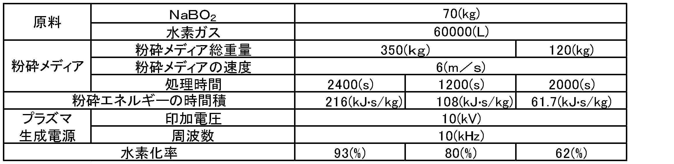
表中、水素化率(転化率)は、次のように算出した。まず、処理後の被処理物中に含まれるテトラヒドロほう酸ナトリウムを加水分解し、それにより生成した水素を定量した。水素量は、生成した気体容積を測定したうえで、気体を空気にて200倍希釈したものを水素検知管(光明理化学工業株式会社製、測定濃度範囲0.05~0.8%)で測定した水素濃度から算出した。そして、100%転化した場合の水素量を基準とし、上記のように定量された水素量から、水素化率を算出した。
(評価2)
フーリエ変換赤外分光光度計FT/IR-6300(日本分光株式会社製、製品名)を用いて、処理時間の異なる4種類の試料の赤外吸収スペクトルを測定した。測定の結果、無水メタほう酸ナトリウムに由来するB-O結合のピークが減少し、テトラヒドロほう酸ナトリウムに由来するB-H結合のピークが増加した。これにより、無水メタほう酸ナトリウムに対するプラズマ処理により、テトラヒドロほう酸ナトリウムが得られることを確認した。
フーリエ変換赤外分光光度計FT/IR-6300(日本分光株式会社製、製品名)を用いて、処理時間の異なる4種類の試料の赤外吸収スペクトルを測定した。測定の結果、無水メタほう酸ナトリウムに由来するB-O結合のピークが減少し、テトラヒドロほう酸ナトリウムに由来するB-H結合のピークが増加した。これにより、無水メタほう酸ナトリウムに対するプラズマ処理により、テトラヒドロほう酸ナトリウムが得られることを確認した。
また、プラズマ処理後の試料について、XRDにより結晶構造を解析した。得られた試料にはNa0.6B0.9H4.0という組成を有するテトラヒドロほう酸ナトリウムが含まれていた。
(実施例3)
図1、図2、図3、図8及び図9に示される製造装置1を用いて、テトラヒドロほう酸塩の製造を行った。ほう酸塩としてNaBO2・4H2O(メタほう酸ナトリウム四水和物:キシダ化学株式会社製、含量98質量%)を準備した。これをボールミルで粉砕処理しながら160℃で15分間加熱して結晶水を除去し、粒状のNaBO2(無水メタほう酸ナトリウム)を得た。粒状のNaBO2の平均粒子径は100 μmであった。平均粒子径はデジタルマイクロスコープにより測定した。
図1、図2、図3、図8及び図9に示される製造装置1を用いて、テトラヒドロほう酸塩の製造を行った。ほう酸塩としてNaBO2・4H2O(メタほう酸ナトリウム四水和物:キシダ化学株式会社製、含量98質量%)を準備した。これをボールミルで粉砕処理しながら160℃で15分間加熱して結晶水を除去し、粒状のNaBO2(無水メタほう酸ナトリウム)を得た。粒状のNaBO2の平均粒子径は100 μmであった。平均粒子径はデジタルマイクロスコープにより測定した。
次に、NaBH4を40 kg生成することを想定し、ボールミル容器2内にNaBO2及び粉砕メディア(平均径30 mmクロム鋼球)を所定量入れ、ボールミル容器2内を真空引きした。これによりボールミル容器2内の空気(酸素)を排気し、その後、水素を注入した。
モータ7の電源を入れ、ボールミル容器2の回転を開始した。ボールミル容器2の回転中はボールミル容器2内を300℃に加熱するとともに、ボールミル容器2内の圧力が大気圧となるように水素を循環フロー注入した。循環フローにより取り出されたボールミル容器2内雰囲気は冷却コンデンサにより処理され、水分と水素とを分離した後、水素をボールミル容器2内に再注入した。被処理物の単位重量当たりの粉砕エネルギーの時間積E(kJ・s/kg)が所定値になるまで、ボールミル容器2の回転を継続した。
モータ7の電源を入れ、ボールミル容器2の回転を開始した直後、ボールミル容器2の内壁に設けられている一対の電極17Bの間に三相交流を全波整流した3.3 ms脈動する直流電圧を、8 msの間は通電し2 msの間は非通電とする比率でON・OFFさせる、5Vのパルス電圧を印加した。反応容器内部で流動する粉砕メディア(平均径30 mmクロム鋼球)衝突時に粉砕メディア間あるいは反応容器内壁と粉砕メディアの衝突時に衝突箇所においてスパーク状の高温水素プラズマが生成された。水素プラズマ生成はボールミル容器2の回転を継続している間、継続した。
その後、プラズマ生成及び回転を停止し、処理後の被処理物を取り出した。被処理物から、テトラヒドロほう酸ナトリウムと、粉砕メディアとを分離しし、所望のテトラヒドロほう酸ナトリウムを得た。なお、以上の実験条件の詳細を以下の表3に示す。
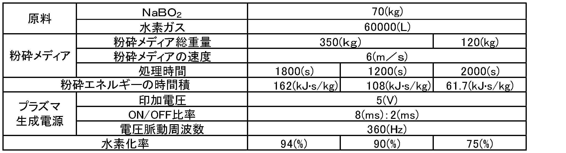
表中、水素化率(転化率)は、次のように算出した。まず、処理後の被処理物中に含まれるテトラヒドロほう酸ナトリウムを加水分解し、それにより生成した水素を定量した。水素量は、生成した気体容積を測定したうえで、気体を空気にて200倍希釈したものを水素検知管(光明理化学工業株式会社製、測定濃度範囲0.05~0.8%)で測定した水素濃度から算出した。そして、100%転化した場合の水素量を基準とし、上記のように定量された水素量から、水素化率を算出した。
(評価3)
フーリエ変換赤外分光光度計FT/IR-6300(日本分光株式会社製、製品名)を用いて、処理時間の異なる4種類の試料の赤外吸収スペクトルを測定した。測定の結果、無水メタほう酸ナトリウムに由来するB-O結合のピークが減少し、テトラヒドロほう酸ナトリウムに由来するB-H結合のピークが増加した。これにより、無水メタほう酸ナトリウムに対するプラズマ処理により、テトラヒドロほう酸ナトリウムが得られることを確認した。
フーリエ変換赤外分光光度計FT/IR-6300(日本分光株式会社製、製品名)を用いて、処理時間の異なる4種類の試料の赤外吸収スペクトルを測定した。測定の結果、無水メタほう酸ナトリウムに由来するB-O結合のピークが減少し、テトラヒドロほう酸ナトリウムに由来するB-H結合のピークが増加した。これにより、無水メタほう酸ナトリウムに対するプラズマ処理により、テトラヒドロほう酸ナトリウムが得られることを確認した。
また、プラズマ処理後の試料について、XRDにより結晶構造を解析した。得られた試料にはNa0.6B0.9H4.0という組成を有するテトラヒドロほう酸ナトリウムが含まれていた。
(実施例4)
図1、図2、図3、図10及び図11に示される製造装置1を用いて、テトラヒドロほう酸塩の製造を行った。ほう酸塩としてNaBO2・4H2O(メタほう酸ナトリウム四水和物:キシダ化学株式会社製、含量98質量%)を準備した。これをボールミルで粉砕処理しながら160℃で15分間加熱して結晶水を除去し、粒状のNaBO2(無水メタほう酸ナトリウム)を得た。粒状のNaBO2の平均粒子径は100 μmであった。平均粒子径はデジタルマイクロスコープにより測定した。
図1、図2、図3、図10及び図11に示される製造装置1を用いて、テトラヒドロほう酸塩の製造を行った。ほう酸塩としてNaBO2・4H2O(メタほう酸ナトリウム四水和物:キシダ化学株式会社製、含量98質量%)を準備した。これをボールミルで粉砕処理しながら160℃で15分間加熱して結晶水を除去し、粒状のNaBO2(無水メタほう酸ナトリウム)を得た。粒状のNaBO2の平均粒子径は100 μmであった。平均粒子径はデジタルマイクロスコープにより測定した。
次に、NaBH4を40 kg生成することを想定し、ボールミル容器2内にNaBO2及び粉砕メディア(平均径30 mmクロム鋼球)を所定量入れ、ボールミル容器2内を真空引きした。これによりボールミル容器2内の空気(酸素)を排気し、その後水素を注入した。
モータ7の電源を入れ、ボールミル容器2の回転を開始した。ボールミル容器2の回転中はボールミル容器2内を300℃に加熱するとともに、ボールミル容器2内の圧力が大気圧となるように水素を循環フロー注入した。循環フローにより取り出されたボールミル容器2内雰囲気は冷却コンデンサにより処理され、水分と水素とを分離した後、水素をボールミル容器2内に再注入した。被処理物の単位重量当たりの粉砕エネルギーの時間積E(kJ・s/kg)が所定値になるまで、ボールミル容器2の回転を継続した。
モータ7の電源を入れ、ボールミル容器2の回転を開始した直後、ボールミル容器2の内壁に設けられている一対の電極17Cの間に三相交流を全波整流した3.3 ms脈動する直流電圧を、8 msの間は通電し2 msの間は非通電とする比率でON・OFFさせる、5Vのパルス電圧を印加した。反応容器内部で流動する粉砕メディア(平均径30 mmクロム鋼球)衝突時に粉砕メディア間あるいは反応容器内壁と粉砕メディアの衝突時に衝突箇所においてスパーク状の高温水素プラズマが生成された。水素プラズマ生成はボールミル容器2の回転を継続している間、継続した。
その後、プラズマ生成及び回転を停止し、処理後の被処理物を取り出した。被処理物から、テトラヒドロほう酸ナトリウムと、粉砕メディアとを分離しし、所望のテトラヒドロほう酸ナトリウムを得た。なお、以上の実験条件の詳細を以下の表4に示す。

表中、水素化率(転化率)は、次のように算出した。まず、処理後の被処理物中に含まれるテトラヒドロほう酸ナトリウムを加水分解し、それにより生成した水素を定量した。水素量は、生成した気体容積を測定したうえで、気体を空気にて200倍希釈したものを水素検知管(光明理化学工業株式会社製、測定濃度範囲0.05~0.8%)で測定した水素濃度から算出した。そして、100%転化した場合の水素量を基準とし、上記のように定量された水素量から、水素化率を算出した。
(評価4)
フーリエ変換赤外分光光度計FT/IR-6300(日本分光株式会社製、製品名)を用いて、処理時間の異なる4種類の試料の赤外吸収スペクトルを測定した。測定の結果、無水メタほう酸ナトリウムに由来するB-O結合のピークが減少し、テトラヒドロほう酸ナトリウムに由来するB-H結合のピークが増加した。これにより、無水メタほう酸ナトリウムに対するプラズマ処理により、テトラヒドロほう酸ナトリウムが得られることを確認した。
フーリエ変換赤外分光光度計FT/IR-6300(日本分光株式会社製、製品名)を用いて、処理時間の異なる4種類の試料の赤外吸収スペクトルを測定した。測定の結果、無水メタほう酸ナトリウムに由来するB-O結合のピークが減少し、テトラヒドロほう酸ナトリウムに由来するB-H結合のピークが増加した。これにより、無水メタほう酸ナトリウムに対するプラズマ処理により、テトラヒドロほう酸ナトリウムが得られることを確認した。
また、プラズマ処理後の試料について、XRDにより結晶構造を解析した。得られた試料にはNa0.6B0.9H4.0という組成を有するテトラヒドロほう酸ナトリウムが含まれていた。
(実施例5)
図1、図2、図3、図12及び図13に示される製造装置1を用いて、テトラヒドロほう酸塩の製造を行った。ほう酸塩としてNaBO2・4H2O(メタほう酸ナトリウム四水和物:キシダ化学株式会社製、含量98質量%)を準備した。これをボールミルで粉砕処理しながら160℃で15分間加熱して結晶水を除去し、粒状のNaBO2(無水メタほう酸ナトリウム)を得た。粒状のNaBO2の平均粒子径は100 μmであった。平均粒子径はデジタルマイクロスコープにより測定した。
図1、図2、図3、図12及び図13に示される製造装置1を用いて、テトラヒドロほう酸塩の製造を行った。ほう酸塩としてNaBO2・4H2O(メタほう酸ナトリウム四水和物:キシダ化学株式会社製、含量98質量%)を準備した。これをボールミルで粉砕処理しながら160℃で15分間加熱して結晶水を除去し、粒状のNaBO2(無水メタほう酸ナトリウム)を得た。粒状のNaBO2の平均粒子径は100 μmであった。平均粒子径はデジタルマイクロスコープにより測定した。
次に、NaBH4を40 kg生成することを想定し、ボールミル容器2内にNaBO2及び粉砕メディア(平均径30 mmクロム鋼球)を所定量入れ、ボールミル容器2内を真空引きした。これによりボールミル容器2内の空気(酸素)を排気し、その後、水素を注入した。
モータ7の電源を入れ、ボールミル容器2の回転を開始した。ボールミル容器2の回転中はボールミル容器2内を300℃に加熱するとともに、ボールミル容器2内の圧力が大気圧となるように水素を循環フロー注入した。循環フローにより取り出されたボールミル容器2内雰囲気は冷却コンデンサにより処理され、水分と水素とを分離した後、水素をボールミル容器2内に再注入した。被処理物の単位重量当たりの粉砕エネルギーの時間積E(kJ・s/kg)が所定値になるまで、ボールミル容器2の回転を継続した。
モータ7の電源を入れ、ボールミル容器2の回転を開始した直後、ボールミル容器2の内壁に設けられている一対の電極17D間に三相交流を全波整流した3.3 ms脈動する直流電圧を、8 msの間は通電し2 msの間は非通電とする比率でON・OFFさせる、5Vのパルス電圧を印加した。反応容器内部で流動する粉砕メディア(平均径30 mmクロム鋼球)衝突時に粉砕メディア間あるいは反応容器内壁と粉砕メディアの衝突時に衝突箇所においてスパーク状の高温水素プラズマが生成された。水素プラズマ生成はボールミル容器2の回転を継続している間、継続した。
その後、プラズマ生成及び回転を停止し、処理後の被処理物を取り出した。被処理物から、テトラヒドロほう酸ナトリウムと、粉砕メディアとを分離しし、所望のテトラヒドロほう酸ナトリウムを得た。なお、以上の実験条件の詳細を以下の表5に示す。

表中、水素化率(転化率)は、次のように算出した。まず、処理後の被処理物中に含まれるテトラヒドロほう酸ナトリウムを加水分解し、それにより生成した水素を定量した。水素量は、生成した気体容積を測定したうえで、気体を空気にて200倍希釈したものを水素検知管(光明理化学工業株式会社製、測定濃度範囲0.05~0.8%)で測定した水素濃度から算出した。そして、100%転化した場合の水素量を基準とし、上記のように定量された水素量から、水素化率を算出した。
(評価5)
フーリエ変換赤外分光光度計FT/IR-6300(日本分光株式会社製、製品名)を用いて、処理時間の異なる4種類の試料の赤外吸収スペクトルを測定した。測定の結果、無水メタほう酸ナトリウムに由来するB-O結合のピークが減少し、テトラヒドロほう酸ナトリウムに由来するB-H結合のピークが増加した。これにより、無水メタほう酸ナトリウムに対するプラズマ処理により、テトラヒドロほう酸ナトリウムが得られることを確認した。
フーリエ変換赤外分光光度計FT/IR-6300(日本分光株式会社製、製品名)を用いて、処理時間の異なる4種類の試料の赤外吸収スペクトルを測定した。測定の結果、無水メタほう酸ナトリウムに由来するB-O結合のピークが減少し、テトラヒドロほう酸ナトリウムに由来するB-H結合のピークが増加した。これにより、無水メタほう酸ナトリウムに対するプラズマ処理により、テトラヒドロほう酸ナトリウムが得られることを確認した。
また、プラズマ処理後の試料について、XRDにより結晶構造を解析した。得られた試料にはNa0.6B0.9H4.0という組成を有するテトラヒドロほう酸ナトリウムが含まれていた。
(実施例6)
図1、図2、図3、図14及び図15に示される製造装置1を用いて、テトラヒドロほう酸塩の製造を行った。ほう酸塩としてNaBO2・4H2O(メタほう酸ナトリウム四水和物:キシダ化学株式会社製、含量98質量%)を準備した。これをボールミルで粉砕処理しながら160℃で15分間加熱して結晶水を除去し、粒状のNaBO2(無水メタほう酸ナトリウム)を得た。粒状のNaBO2の平均粒子径は100 μmであった。平均粒子径はデジタルマイクロスコープにより測定した。
図1、図2、図3、図14及び図15に示される製造装置1を用いて、テトラヒドロほう酸塩の製造を行った。ほう酸塩としてNaBO2・4H2O(メタほう酸ナトリウム四水和物:キシダ化学株式会社製、含量98質量%)を準備した。これをボールミルで粉砕処理しながら160℃で15分間加熱して結晶水を除去し、粒状のNaBO2(無水メタほう酸ナトリウム)を得た。粒状のNaBO2の平均粒子径は100 μmであった。平均粒子径はデジタルマイクロスコープにより測定した。
次に、NaBH4を40 kg生成することを想定し、ボールミル容器2内にNaBO2及び粉砕メディア(平均径30 mmクロム鋼球)を所定量入れ、ボールミル容器2内を真空引きした。これによりボールミル容器2内の空気(酸素)を排気し、その後水素を注入した。
モータ7の電源を入れ、ボールミル容器2の回転を開始した。ボールミル容器2の回転中はボールミル容器2内を300℃に加熱するとともに、ボールミル容器2内の圧力が大気圧となるように水素を循環フロー注入した。循環フローにより取り出されたボールミル容器2内雰囲気は冷却コンデンサにより処理され、水分と水素とを分離した後、水素をボールミル容器2内に再注入した。被処理物の単位重量当たりの粉砕エネルギーの時間積E(kJ・s/kg)が所定値になるまで、ボールミル容器2の回転を継続した。
モータ7の電源を入れ、ボールミル容器2の回転を開始した直後、ボールミル容器2の内壁に設けられている一対の電極17Eの間に三相交流を全波整流した3.3 ms脈動する直流電圧を、8 msの間は通電し2 msの間は非通電とする比率でON・OFFさせる、5Vのパルス電圧を印加した。反応容器内部で流動する粉砕メディア(平均径30 mmクロム鋼球)衝突時に粉砕メディア間あるいは反応容器内壁と粉砕メディアの衝突時に衝突箇所においてスパーク状の高温水素プラズマが生成された。水素プラズマ生成はボールミル容器2の回転を継続している間、継続した。
その後、プラズマ生成及び回転を停止し、処理後の被処理物を取り出した。被処理物から、テトラヒドロほう酸ナトリウムと、粉砕メディアとを分離しし、所望のテトラヒドロほう酸ナトリウムを得た。なお、以上の実験条件の詳細を以下の表6に示す。
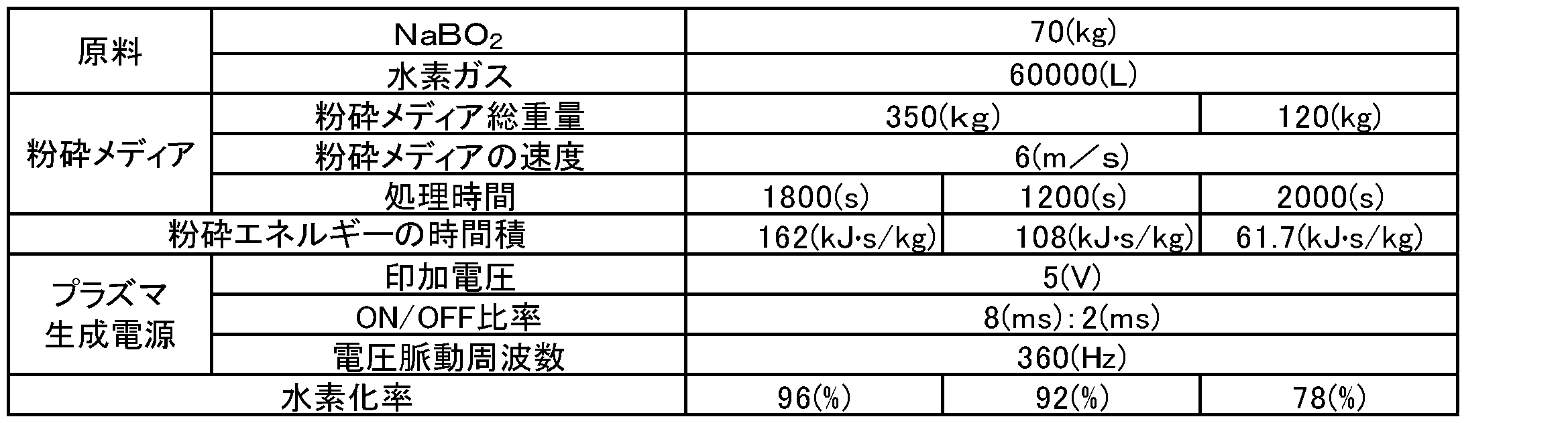
表中、水素化率(転化率)は、次のように算出した。まず、処理後の被処理物中に含まれるテトラヒドロほう酸ナトリウムを加水分解し、それにより生成した水素を定量した。水素量は、生成した気体容積を測定したうえで、気体を空気にて200倍希釈したものを水素検知管(光明理化学工業株式会社製、測定濃度範囲0.05~0.8%)で測定した水素濃度から算出した。そして、100%転化した場合の水素量を基準とし、上記のように定量された水素量から、水素化率を算出した。
(評価6)
フーリエ変換赤外分光光度計FT/IR-6300(日本分光株式会社製、製品名)を用いて、処理時間の異なる4種類の試料の赤外吸収スペクトルを測定した。測定の結果、無水メタほう酸ナトリウムに由来するB-O結合のピークが減少し、テトラヒドロほう酸ナトリウムに由来するB-H結合のピークが増加した。これにより、無水メタほう酸ナトリウムに対するプラズマ処理により、テトラヒドロほう酸ナトリウムが得られることを確認した。
フーリエ変換赤外分光光度計FT/IR-6300(日本分光株式会社製、製品名)を用いて、処理時間の異なる4種類の試料の赤外吸収スペクトルを測定した。測定の結果、無水メタほう酸ナトリウムに由来するB-O結合のピークが減少し、テトラヒドロほう酸ナトリウムに由来するB-H結合のピークが増加した。これにより、無水メタほう酸ナトリウムに対するプラズマ処理により、テトラヒドロほう酸ナトリウムが得られることを確認した。
また、プラズマ処理後の試料について、XRDにより結晶構造を解析した。得られた試料にはNa0.6B0.9H4.0という組成を有するテトラヒドロほう酸ナトリウムが含まれていた。
以上、実施例1~6において、本開示の方法MT及び製造装置1を用いることでテトラヒドロほう酸ナトリウムが得られることが確認された。
1…製造装置、2…ボールミル容器、2d…処理室、6…駆動部、11a…ガス供給部、14…電源、15…第1プラズマ生成部、15A…第2プラズマ生成部、15B…第3プラズマ生成部、15C…第4プラズマ生成部、15D…第5プラズマ生成部、15E…第6プラズマ生成部、16…誘電体部材、17,17B,17C,17D,17E…一対の電極、18,18B,18C,18D,18E…絶縁体、21…プラズマジェットノズル。
Claims (15)
- ほう酸塩を粉砕しつつ水素プラズマにさらす水素化処理工程を備える、テトラヒドロほう酸塩の製造方法。
- 前記水素プラズマは、水素ガス及び炭化水素ガスの少なくとも一種を含む原料ガスを用いて生成される、請求項1に記載のテトラヒドロほう酸塩の製造方法。
- 前記水素プラズマは、誘電体バリア放電で生成されたプラズマである、請求項1又は2に記載のテトラヒドロほう酸塩の製造方法。
- 前記水素プラズマは、プラズマジェットとして前記ほう酸塩に提供される、請求項1又は2に記載のテトラヒドロほう酸塩の製造方法。
- 前記水素プラズマは、高温プラズマである、請求項1又は2に記載のテトラヒドロほう酸塩の製造方法。
- 前記水素化処理工程では、前記ほう酸塩を加熱しながら粉砕しつつ水素プラズマにさらす、請求項1~5のいずれか一項に記載のテトラヒドロほう酸塩の製造方法。
- 前記水素化処理工程において、水素と結合し得る還元材を前記ほう酸塩とともに同時に処理する、請求項1~6のいずれか一項に記載のテトラヒドロほう酸塩の製造方法。
- 前記ほう酸塩はメタほう酸ナトリウムである、請求項1~7のいずれか一項に記載のテトラヒドロほう酸塩の製造方法。
- 前記水素化処理工程の前に、前記ほう酸塩を加熱する予備加熱工程をさらに備える、請求項1~8のいずれか一項に記載のテトラヒドロほう酸塩の製造方法。
- 前記水素化処理工程の前に、テトラヒドロほう酸塩と水とを反応させて前記ほう酸塩を得るほう酸塩調製工程をさらに備える、請求項1~8のいずれか一項に記載のテトラヒドロほう酸塩の製造方法。
- 前記予備加熱工程の前に、テトラヒドロほう酸塩と水とを反応させて前記ほう酸塩を得るほう酸塩調製工程をさらに備える、請求項9に記載のテトラヒドロほう酸塩の製造方法。
- 粉砕メディア及びほう酸塩を収容する処理室を内部に有するボールミル容器と、
前記ボールミル容器を回転させる駆動部と、
前記処理室へ原料ガスを供給するガス供給部と、
電圧を印加する電源と、
前記処理室の内壁面の少なくとも一部を構成する誘電体部材と、前記誘電体部材に接続され、前記電源から電圧が印加される少なくとも一対の電極と、前記少なくとも一対の電極間を絶縁する絶縁体とを有するプラズマ生成部と、
を備え、
前記駆動部は、前記ボールミル容器を回転させることにより前記ほう酸塩を粉砕し、
前記ガス供給部は、前記処理室を前記原料ガスの雰囲気とし、
前記プラズマ生成部は、前記原料ガスの雰囲気中の前記処理室にて前記電源から印加された電圧に基づいた誘電体バリア放電により前記誘電体部材の表面に水素プラズマを生成し、前記ボールミル容器の回転中において前記ほう酸塩を前記水素プラズマにさらす、
テトラヒドロほう酸塩の製造装置。 - 粉砕メディア及びほう酸塩を収容する処理室を内部に有するボールミル容器と、
前記ボールミル容器を回転させる駆動部と、
電圧が印加されることで水素プラズマのプラズマジェットを生成可能であり、前記処理室に収容された前記粉砕メディア及び前記ほう酸塩の滞留箇所へ前記プラズマジェットを噴射するように前記処理室に固定配置されるプラズマジェットノズルを有するプラズマ生成部と、
前記プラズマ生成部へ電圧を印加する電源と、
前記プラズマ生成部へ原料ガスを供給するガス供給部と、
を備え、
前記駆動部は、前記ボールミル容器を回転させることにより前記ほう酸塩を粉砕し、
前記プラズマ生成部は、前記電源から印加された電圧及び前記ガス供給部から供給された前記原料ガスに基づいて前記プラズマジェットを生成し、前記ボールミル容器の回転中において前記粉砕メディア及び前記ほう酸塩の滞留箇所へプラズマジェットノズルから前記プラズマジェットを噴射する、
テトラヒドロほう酸塩の製造装置。 - 電気伝導性を有する粉砕メディア及びほう酸塩を収容する処理室を内部に有するボールミル容器と、
前記ボールミル容器を回転させる駆動部と、
前記処理室へ原料ガスを供給するガス供給部と、
前記処理室の内壁面の少なくとも一部、又は、前記処理室に設けられたリフタ部材の少なくとも一部を構成する少なくとも一対の電極と、前記少なくとも一対の電極間を絶縁する絶縁体とを有するプラズマ生成部と、
前記少なくとも一対の電極間に電圧を印加する電源と、
を備え、
前記駆動部は、前記ボールミル容器を回転させることにより、前記ほう酸塩を粉砕し、かつ、流動させた前記粉砕メディアを介して前記少なくとも一対の電極間の通電状態を変化させ、
前記ガス供給部は、前記処理室を前記原料ガスの雰囲気とし、
前記プラズマ生成部は、前記原料ガスの雰囲気中の前記処理室にて前記電源から電圧が印加されることにより、前記ボールミル容器の回転中において前記粉砕メディアの表面にスパーク状の水素プラズマを生成し、前記ほう酸塩を前記水素プラズマにさらす、
テトラヒドロほう酸塩の製造装置。 - 下記一般式(A)又は(B)で表される組成を有するテトラヒドロほう酸塩。
MxByHz (A)
NsBtHu (B)
[式(A)中、MはLi、Na及びKからなる群より選択される少なくとも一種であり、xは0.05以上1.0未満であり、yは0.6以上1.0未満であり、zは4.0である。式(B)中、NはCa及びMgからなる群より選択される少なくとも一種であり、sは0.05以上1.0未満であり、tは1.2以上2.0未満であり、uは8.0である。]
Priority Applications (3)
| Application Number | Priority Date | Filing Date | Title |
|---|---|---|---|
| US17/271,367 US12275643B2 (en) | 2018-08-27 | 2019-02-08 | Method for producing tetrahydroboric acid salt, device for producing tetrahydroboric acid salt, and tetrahydroboric acid salt |
| CN201980056438.2A CN112654580B (zh) | 2018-08-27 | 2019-02-08 | 四氢硼酸盐的制造方法、四氢硼酸盐的制造装置和四氢硼酸盐 |
| DE112019004292.0T DE112019004292T5 (de) | 2018-08-27 | 2019-02-08 | Verfahren zur Herstellung von Tetrahydroborsäuresalz, Vorrichtung zur Erzeugung von Tetrahydroborsäuresalz und Tetrahyroborsäuresalz |
Applications Claiming Priority (2)
| Application Number | Priority Date | Filing Date | Title |
|---|---|---|---|
| JP2018-158478 | 2018-08-27 | ||
| JP2018158478A JP6973331B2 (ja) | 2018-08-27 | 2018-08-27 | テトラヒドロほう酸塩の製造方法、テトラヒドロほう酸塩の製造装置及びテトラヒドロほう酸塩 |
Publications (1)
| Publication Number | Publication Date |
|---|---|
| WO2020044596A1 true WO2020044596A1 (ja) | 2020-03-05 |
Family
ID=69644064
Family Applications (1)
| Application Number | Title | Priority Date | Filing Date |
|---|---|---|---|
| PCT/JP2019/004717 Ceased WO2020044596A1 (ja) | 2018-08-27 | 2019-02-08 | テトラヒドロほう酸塩の製造方法、テトラヒドロほう酸塩の製造装置及びテトラヒドロほう酸塩 |
Country Status (5)
| Country | Link |
|---|---|
| US (1) | US12275643B2 (ja) |
| JP (1) | JP6973331B2 (ja) |
| CN (1) | CN112654580B (ja) |
| DE (1) | DE112019004292T5 (ja) |
| WO (1) | WO2020044596A1 (ja) |
Cited By (1)
| Publication number | Priority date | Publication date | Assignee | Title |
|---|---|---|---|---|
| JP2023549718A (ja) * | 2020-11-06 | 2023-11-29 | 華南理工大学 | 連続的な低温プラズマによる粉末処理及びボールミリング生産装置並びにその方法 |
Families Citing this family (4)
| Publication number | Priority date | Publication date | Assignee | Title |
|---|---|---|---|---|
| JP7540335B2 (ja) * | 2020-12-28 | 2024-08-27 | 新東工業株式会社 | 処理ガス調整装置、処理ガス調整方法、及び、金属水素化物を製造するシステム |
| JP7707747B2 (ja) * | 2021-08-23 | 2025-07-15 | 新東工業株式会社 | 処理装置及び処理方法 |
| JPWO2023238829A1 (ja) * | 2022-06-06 | 2023-12-14 | ||
| CN116037273A (zh) * | 2023-02-06 | 2023-05-02 | 上海理工大学 | 一种新型等离子体球磨装置 |
Citations (4)
| Publication number | Priority date | Publication date | Assignee | Title |
|---|---|---|---|---|
| JPH0867503A (ja) * | 1994-08-30 | 1996-03-12 | Nisshin Steel Co Ltd | 水素化チタン超微粒子の製造方法 |
| JP2006104055A (ja) * | 2004-10-08 | 2006-04-20 | Rohm & Haas Co | 水素化ホウ素ナトリウムの直接元素合成 |
| JP2011148644A (ja) * | 2010-01-19 | 2011-08-04 | Toyota Motor Corp | 水素貯蔵材料の水素化方法 |
| WO2015190004A1 (ja) * | 2014-06-11 | 2015-12-17 | 吉崎 敦浩 | 水素化ホウ素ナトリウムの製造方法 |
Family Cites Families (14)
| Publication number | Priority date | Publication date | Assignee | Title |
|---|---|---|---|---|
| JP2004224684A (ja) | 2002-11-27 | 2004-08-12 | Materials & Energy Research Institute Tokyo Ltd | テトラヒドロホウ酸塩の製造方法 |
| JP4032625B2 (ja) * | 2000-09-27 | 2008-01-16 | 松下電工株式会社 | プラズマ処理装置及びプラズマ点灯方法 |
| JP2004103423A (ja) * | 2002-09-10 | 2004-04-02 | Matsushita Electric Works Ltd | プラズマ処理方法及びプラズマ処理装置 |
| US7303657B2 (en) | 2003-10-24 | 2007-12-04 | Battelle Energy Alliance, Llc | Method and apparatus for chemical synthesis |
| US7420027B2 (en) * | 2004-11-17 | 2008-09-02 | Battelle Energy Alliance, Llc | Method for producing a borohydride |
| US7354561B2 (en) | 2004-11-17 | 2008-04-08 | Battelle Energy Alliance, Llc | Chemical reactor and method for chemically converting a first material into a second material |
| JP2006143537A (ja) * | 2004-11-22 | 2006-06-08 | Materials & Energy Research Institute Tokyo Ltd | テトラヒドロホウ酸塩の製造方法 |
| EP1787952A1 (fr) * | 2005-11-17 | 2007-05-23 | L'AIR LIQUIDE, Société Anonyme pour l'Etude et l'Exploitation des Procédés Georges Claude | Procédé de préparation d'alcoolate alcalin et sa mise en oeuvre pour régénérer du borohydrure de sodium à partir de métaborate de sodium |
| CN100386337C (zh) * | 2006-01-24 | 2008-05-07 | 北京工业大学 | 一种原位合成制备高纯GdH2块体材料的方法 |
| JP5495010B2 (ja) * | 2009-07-31 | 2014-05-21 | バイオコーク技研株式会社 | 酸化マグネシウム還元方法及び反応装置 |
| WO2011139708A2 (en) * | 2010-04-26 | 2011-11-10 | Toyota Motor Engineering & Manufacturing North America, Inc. | Improved hydrogen release from complex metal hydrides by solvation in ionic liquids |
| CN102910586A (zh) * | 2012-10-26 | 2013-02-06 | 华南理工大学 | 一种Mg2NiH4储氢材料及其制备方法与应用 |
| CN103482571B (zh) * | 2013-09-26 | 2015-04-01 | 中国工程物理研究院激光聚变研究中心 | 一种氢化铍材料的制备方法及装置 |
| CN107344713B (zh) * | 2017-07-12 | 2019-05-28 | 南方科技大学 | 一种合成M(BH4)n和/或M2/nB12H12的方法 |
-
2018
- 2018-08-27 JP JP2018158478A patent/JP6973331B2/ja active Active
-
2019
- 2019-02-08 DE DE112019004292.0T patent/DE112019004292T5/de active Pending
- 2019-02-08 CN CN201980056438.2A patent/CN112654580B/zh active Active
- 2019-02-08 US US17/271,367 patent/US12275643B2/en active Active
- 2019-02-08 WO PCT/JP2019/004717 patent/WO2020044596A1/ja not_active Ceased
Patent Citations (4)
| Publication number | Priority date | Publication date | Assignee | Title |
|---|---|---|---|---|
| JPH0867503A (ja) * | 1994-08-30 | 1996-03-12 | Nisshin Steel Co Ltd | 水素化チタン超微粒子の製造方法 |
| JP2006104055A (ja) * | 2004-10-08 | 2006-04-20 | Rohm & Haas Co | 水素化ホウ素ナトリウムの直接元素合成 |
| JP2011148644A (ja) * | 2010-01-19 | 2011-08-04 | Toyota Motor Corp | 水素貯蔵材料の水素化方法 |
| WO2015190004A1 (ja) * | 2014-06-11 | 2015-12-17 | 吉崎 敦浩 | 水素化ホウ素ナトリウムの製造方法 |
Cited By (2)
| Publication number | Priority date | Publication date | Assignee | Title |
|---|---|---|---|---|
| JP2023549718A (ja) * | 2020-11-06 | 2023-11-29 | 華南理工大学 | 連続的な低温プラズマによる粉末処理及びボールミリング生産装置並びにその方法 |
| JP7628344B2 (ja) | 2020-11-06 | 2025-02-10 | 華南理工大学 | 連続的な低温プラズマによる粉末処理及びボールミリング生産装置並びにその方法 |
Also Published As
| Publication number | Publication date |
|---|---|
| CN112654580B (zh) | 2024-04-16 |
| JP6973331B2 (ja) | 2021-11-24 |
| US20210323820A1 (en) | 2021-10-21 |
| US12275643B2 (en) | 2025-04-15 |
| DE112019004292T5 (de) | 2021-05-20 |
| CN112654580A (zh) | 2021-04-13 |
| JP2020033201A (ja) | 2020-03-05 |
Similar Documents
| Publication | Publication Date | Title |
|---|---|---|
| JP6973331B2 (ja) | テトラヒドロほう酸塩の製造方法、テトラヒドロほう酸塩の製造装置及びテトラヒドロほう酸塩 | |
| CN111936414B (zh) | 四氢硼酸盐的制造方法和四氢硼酸盐 | |
| US20230405674A1 (en) | Continuous low-temperature plasma powder treatment and ball-milling production device and method thereof | |
| CN104549658A (zh) | 冷场等离子体放电辅助高能球磨粉体的应用方法及装置 | |
| JP2018501099A (ja) | 粉体の高エネルギー球入破砕における冷プラズマ放電支援の応用方法および装置 | |
| US20110297532A1 (en) | Apparatus and method for producing plasma during milling for processing of material compositions | |
| CN104550903A (zh) | 铬粉的氢等离子脱氧方法 | |
| JP7070066B2 (ja) | テトラヒドロほう酸塩の製造方法 | |
| KR101409160B1 (ko) | 질화알루미늄 나노분말의 제조방법 | |
| JP5075899B2 (ja) | カルシウムシアナミドを含む粉体、該粉体の製造方法及びその装置 | |
| JP7286110B2 (ja) | 水素化マグネシウムの製造方法及びテトラヒドロほう酸塩の製造方法 | |
| CN105025649A (zh) | 一种低气压下产生感应耦合热等离子体的装置与方法 | |
| JP7257653B2 (ja) | 水素化マグネシウムの製造方法及びテトラヒドロほう酸塩の製造方法 | |
| JP7120098B2 (ja) | テトラヒドロほう酸塩の製造装置、及びテトラヒドロほう酸塩の製造方法 | |
| CN116213041B (zh) | 用于材料制备和机械化学反应的多能场耦合反应装置 | |
| JP7216962B2 (ja) | テトラヒドロほう酸塩の製造方法 | |
| CN112441558B (zh) | 氢化镁的制造方法和四氢硼酸盐的制造方法 | |
| JP7070067B2 (ja) | テトラヒドロほう酸塩の製造方法 | |
| WO2026060035A1 (en) | Low-temperature microwave-powered plasma reduction system and methodology | |
| JP2021038130A (ja) | テトラヒドロほう酸塩の製造方法 | |
| JP2010095442A (ja) | ナノ粒子作製装置とそれを用いたナノ粒子作製方法 |
Legal Events
| Date | Code | Title | Description |
|---|---|---|---|
| 121 | Ep: the epo has been informed by wipo that ep was designated in this application |
Ref document number: 19854897 Country of ref document: EP Kind code of ref document: A1 |
|
| 122 | Ep: pct application non-entry in european phase |
Ref document number: 19854897 Country of ref document: EP Kind code of ref document: A1 |
|
| WWG | Wipo information: grant in national office |
Ref document number: 17271367 Country of ref document: US |