WO2020044550A1 - エレベータ - Google Patents
エレベータ Download PDFInfo
- Publication number
- WO2020044550A1 WO2020044550A1 PCT/JP2018/032408 JP2018032408W WO2020044550A1 WO 2020044550 A1 WO2020044550 A1 WO 2020044550A1 JP 2018032408 W JP2018032408 W JP 2018032408W WO 2020044550 A1 WO2020044550 A1 WO 2020044550A1
- Authority
- WO
- WIPO (PCT)
- Prior art keywords
- movable body
- car
- moves
- rotating
- hoistway
- Prior art date
- Legal status (The legal status is an assumption and is not a legal conclusion. Google has not performed a legal analysis and makes no representation as to the accuracy of the status listed.)
- Ceased
Links
Images




Classifications
-
- B—PERFORMING OPERATIONS; TRANSPORTING
- B66—HOISTING; LIFTING; HAULING
- B66B—ELEVATORS; ESCALATORS OR MOVING WALKWAYS
- B66B5/00—Applications of checking, fault-correcting, or safety devices in elevators
- B66B5/02—Applications of checking, fault-correcting, or safety devices in elevators responsive to abnormal operating conditions
-
- B—PERFORMING OPERATIONS; TRANSPORTING
- B66—HOISTING; LIFTING; HAULING
- B66B—ELEVATORS; ESCALATORS OR MOVING WALKWAYS
- B66B5/00—Applications of checking, fault-correcting, or safety devices in elevators
- B66B5/02—Applications of checking, fault-correcting, or safety devices in elevators responsive to abnormal operating conditions
- B66B5/16—Braking or catch devices operating between cars, cages, or skips and fixed guide elements or surfaces in hoistway or well
- B66B5/26—Positively-acting devices, e.g. latches, knives
Definitions
- the present invention relates to an elevator in which a car moves up and down a hoistway.
- a running rail that guides a car and a car, a rope having one end connected to the car, a counterweight connected to the other end of the rope, and a hoist on which the rope is wound and moves the rope.
- a skew elevator having the following.
- the hoist is driven, the rope moves.
- the car moves up and down the hoistway extending in a direction inclined with respect to the vertical line (for example, see Patent Document 1).
- the present invention has been made to solve the above-described problems, and an object of the present invention is to provide an elevator that can suppress occurrence of door-open traveling.
- An elevator includes a car that moves up and down a hoistway, a rotating member that is rotatably provided on a car, and a first movable body that is provided on the rotating member and rotates the rotating member by changing its position with respect to the car.
- a movable body climbing member provided on the hoistway, the position of the first movable body with respect to the car changing when the first movable body rides, and a stop position provided on the rotating member and rotating the rotating member.
- a second movable body that moves between the traveling position and a hoistway, and restricts the movement of the second movable body in the moving direction of the car when the position of the second movable body is the stop position;
- a restriction member for releasing restriction of movement of the second movable body in the movement direction when the position of the movable body is the traveling position, wherein the first movable body is movable when the car is on the landing floor. Get on the riding member Raised, the position of the second movable member is the stop position.
- the occurrence of door-open traveling can be suppressed.
- FIG. 2 is a side view showing the skew elevator according to Embodiment 1 of the present invention. It is a side view which shows the principal part of the skew elevator of FIG. It is a top view which shows the principal part of the skew elevator of FIG.
- FIG. 3 is a plan view showing a traveling rail, a stop rail, and a regulating member of FIG. 2.
- FIG. 5 is a plan view showing a state in which the regulating member of FIG. 4 has moved. It is a block diagram which shows the principal part of the skew elevator of FIG.
- FIG. 1 is a side view showing a skew elevator according to Embodiment 1 of the present invention
- FIG. 2 is an enlarged view showing a main part of the skew elevator of FIG. 1
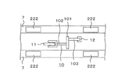
- FIG. It is a top view which shows a principal part.
- the skew elevator includes a car 2 that moves up and down a hoistway 1 extending in a direction inclined with respect to a vertical line, a rope 3 having one end connected to the car 2, and a hoistway connected to the other end of the rope 3. 1 is provided with a counterweight 4 for lifting and lowering 1 and a hoisting machine 5 around which the rope 3 is wound.
- the hoist 5 has a sheave around which the rope 3 is wound, a motor for rotating the sheave, and a brake device for braking the sheave.
- the hoisting machine 5 When the hoisting machine 5 is driven, the rope 3 moves.
- the car 2 and the counterweight 4 move up and down the hoistway 1 in opposite directions.
- One landing entrance 6 is formed at a portion of the hoistway 1 corresponding to each of a plurality of landing floors.
- the skew elevator corresponds to a pair of traveling rails 7 provided on the hoistway 1, a plurality of stop rails 8 provided on the hoistway 1 corresponding to each landing floor, and a corresponding one of the landing floors. And a plurality of regulating members 9 provided on the hoistway 1.
- the running rail 7 is provided over the entire area of the hoistway 1 in the hoisting path of the car 2.
- the skew elevator includes a rotating member 10 rotatably provided on the car 2, a first movable body 11 provided on the rotating member 10, a second movable body 12 provided on the rotating member 10, An elastic member 13 for pressing the member 10.
- the car 2 includes a cab 21 to which a user enters and exits, and a cart 22 that supports the cab 21.
- the trolley 22 has a trolley main body 221 that supports the car room 21, and a plurality of traveling rollers 222 that are rotatably supported by the trolley main body 221 and roll on the respective traveling rails 7.
- the stop rail 8, the regulating member 9, the cab 21, and the bogie main body 221 are omitted.
- the rotating member 10 includes a rotating shaft 101 rotatably supported by the bogie main body 221, a first arm 102 provided on the rotating shaft 101, and a second arm 103 provided on the rotating shaft 101.
- the rotating shaft 101 is arranged to extend in the width direction of the skew elevator.
- the first arm 102 extends outward from the rotation shaft 101 in the radial direction of the rotation shaft 101.
- the second arm 103 extends outward from the rotation shaft 101 in the radial direction of the rotation shaft 101.
- the first arm 102 is arranged on the upper floor side of the second arm 103 in the moving direction of the car 2.
- the first movable body 11 is attached to the tip of the first arm 102.
- the first movable body 11 includes, for example, a roller.
- the second movable body 12 is attached to a distal end of the second arm 103.
- Each of the first movable body 11 and the second movable body 12 changes its position in the height direction with respect to the car 2 as the rotating member 10 rotates.
- the position of the first movable body 11 in the height direction with respect to the car 2 approaches the car 2
- the position of the second movable body 12 in the height direction with respect to the car 2 moves away from the car 2.
- the position of the first movable body 11 in the height direction with respect to the car 2 moves away from the car 2
- the position of the second movable body 12 in the height direction with respect to the car 2 approaches the car 2.
- the stop rail 8 is a movable body riding member on which the first movable body 11 rides. As the first movable body 11 rides on the stop rail 8, the position of the first movable body 11 in the height direction with respect to the car 2 changes.
- the stop rail 8 is arranged on the hoistway 1 such that the first movable body 11 runs on the stop rail 8 when the car 2 is on the landing floor.
- the regulating member 9 has a groove into which the second movable body 12 can be inserted from above. By inserting the second movable body 12 into the groove of the regulating member 9, the movement of the second movable body 12 in the moving direction of the car 2 is regulated.
- the second movable body 12 moves as the rotating member 10 rotates.
- the second movable body 12 has a stop position where the movement of the second movable body 12 in the moving direction of the car 2 is restricted by the regulating member 9, and a stop position of the second movable body 12 in the moving direction of the car 2 by the regulating member 9. It moves between the travel position where the movement restriction is released.
- the second movable body 12 is inserted into the groove of the regulating member 9 from above, the position of the second movable body 12 becomes the stop position.
- the second movable body 12 is pulled upward from the groove of the regulating member 9, the position of the second movable body 12 becomes the traveling position.
- the regulating member 9 is arranged in the hoistway 1 so that the second movable body 12 can be inserted into the groove of the regulating member 9 from above when the car 2 is on the landing floor.
- the elastic member 13 is disposed over the bogie main body 221 and the first arm 102.
- the elastic member 13 is composed of a compression spring.
- the elastic member 13 pushes the first arm 102 in a direction in which the position of the second movable body 12 becomes the traveling position. Thereby, when the first movable body 11 does not ride on the stop rail 8, the position of the second movable body 12 becomes the traveling position.
- the elastic member 13 is not limited to a compression spring, and may be another elastic member.
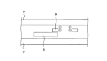
- FIG. 4 is a plan view showing the traveling rail 7, the stop rail 8 and the regulating member 9 of FIG. 2
- FIG. 5 is a plan view showing a state where the regulating member 9 of FIG.
- the regulating member 9 is movable in the width direction of the skew elevator. As the restricting member 9 moves in the width direction of the oblique elevator, the restricting member 9 moves between the restricting position and the release position.
- the regulating position is a position of the regulating member 9 arranged on the moving path of the second movable body 12 in the moving direction of the car 2 when the position of the second movable body 12 is the stop position.
- FIG. 4 shows a state where the regulating member 9 is at the regulating position. In this case, the second movable body 12 is inserted into the groove of the regulating member 9 from above. Thereby, the movement of the car 2 is restricted.
- the release position is a position of the regulating member 9 that deviates from the moving path of the second movable body 12 in the moving direction of the car 2 when the position of the second movable body 12 is the stop position.
- FIG. 5 shows a state in which the regulating member 9 is at the release position. In this case, the restriction on the movement of the car 2 is released.
- FIG. 6 is a block diagram showing a main part of the skew elevator of FIG.
- the skew elevator includes a regulating member moving device 14 that moves the regulating member 9, and a control device 15 that controls driving of the regulating member moving device 14.
- the control device 15 controls the driving of the regulating member moving device 14 such that the regulating member 9 moves from the regulating position to the release position when the car door is at the door closing position and the car 2 is moved up and down. I do.
- the car door moves from the door closed position to the door open position. Thereby, the user can enter and exit the car 2. At this time, even if an abnormality occurs in the brake device of the hoisting machine 5 and the sheave of the hoisting machine 5 is not braked, the occurrence of door-open traveling is suppressed. Thereafter, the car door moves from the door open position to the door closed position.
- the regulating member 9 moves from the regulating position to the release position. Thereby, the regulation of the movement of the car 2 is released. Thereafter, the car 2 moves. Thereby, the riding of the first movable body 11 on the stop rail 8 is released. As a result, the second movable body 12 moves from the stop position to the traveling position.
- the skew elevator according to Embodiment 1 of the present invention when the car 2 is on the landing floor, the first movable body 11 rides on the stop rail 8 and the second movable body 12 Is the stop position. As a result, the occurrence of door-open traveling can be suppressed.
- the rotating member 10 is provided on the rotating shaft 101, the first arm 102 provided on the rotating shaft 101 and having the first movable body 11 attached thereto, and the second movable body 12 provided on the rotating shaft 101. And a second arm 103.
- the second movable body 12 can be moved between the traveling position and the stop position with a simple configuration.
- the skew elevator pushes the first arm 102 in a direction in which the position of the second movable body 12 becomes the traveling position. Accordingly, when the first movable body 11 does not ride on the stop rail 8, the position of the second movable body 12 can be easily set to the traveling position.
- the skew elevator in which the car 2 moves up and down the hoistway 1 extending in the direction inclined with respect to the vertical line has been described.
- the present invention is not limited thereto, and an elevator in which a car moves up and down a hoistway extending in a direction along a vertical line may be used.
Landscapes
- Engineering & Computer Science (AREA)
- Mechanical Engineering (AREA)
- Cage And Drive Apparatuses For Elevators (AREA)
Abstract
戸開走行の発生を抑制することができる斜行エレベータを得る。この斜行エレベータは、かごと、かごに回転可能に設けられた回転部材と、回転部材を回転させる第1可動体と、第1可動体が乗り上げる可動体乗上部材と、停止位置と走行位置との間で移動する第2可動体と、第2可動体の位置が停止位置である場合にかごの移動方向についての第2可動体の移動を規制する規制部材とを備え、かごが乗場階にある場合に、第1可動体が可動体乗上部材に乗り上げて、第2可動体の位置が停止位置となる。
Description
この発明は、昇降路をかごが昇降するエレベータに関する。
従来、かごと、かごを案内する走行レールと、一端部がかごに接続されたロープと、ロープの他端部に接続されたつり合いおもりと、ロープが巻き掛けられ、ロープを移動させる巻上機とを備えた斜行エレベータが知られている。巻上機が駆動することによって、ロープが移動する。ロープが移動することによって、かごは、鉛直線に対して傾斜した方向に延びる昇降路を昇降する(例えば、特許文献1参照)。
かごが乗場階にある場合に、かごドアが戸閉位置から戸開位置に移動する。これにより、利用者は、かごに対して出入することができる。しかしながら、かごドアの位置が戸開位置にある状態で、かごの移動を停止させるブレーキ装置に異常が発生した場合に、戸開走行が発生してしまうという課題があった。
この発明は、上述のような課題を解決するためになされたものであり、その目的は、戸開走行の発生を抑制することができるエレベータを提供するものである。
この発明に係るエレベータは、昇降路を昇降するかごと、かごに回転可能に設けられた回転部材と、回転部材に設けられ、かごに対する位置が変化することによって回転部材を回転させる第1可動体と、昇降路に設けられ、第1可動体が乗り上げることによって第1可動体におけるかごに対する位置が変化する可動体乗上部材と、回転部材に設けられ、回転部材が回転することによって停止位置と走行位置との間で移動する第2可動体と、昇降路に設けられ、第2可動体の位置が停止位置である場合にかごの移動方向についての第2可動体の移動を規制し、第2可動体の位置が走行位置である場合に移動方向についての第2可動体の移動の規制が解除される規制部材とを備え、かごが乗場階にある場合に、第1可動体が可動体乗上部材に乗り上げて、第2可動体の位置が停止位置となる。
この発明に係るエレベータによれば、戸開走行の発生を抑制することができる。
実施の形態1.
図1は、この発明の実施の形態1に係る斜行エレベータを示す側面図、図2は、図1の斜行エレベータの要部を示す拡大図、図3は、図1の斜行エレベータの要部を示す平面図である。斜行エレベータは、鉛直線に対して傾斜した方向に延びる昇降路1を昇降するかご2と、一端部がかご2に接続されたロープ3と、ロープ3の他端部に接続され、昇降路1を昇降するつり合いおもり4と、ロープ3が巻き掛けられた巻上機5とを備えている。
図1は、この発明の実施の形態1に係る斜行エレベータを示す側面図、図2は、図1の斜行エレベータの要部を示す拡大図、図3は、図1の斜行エレベータの要部を示す平面図である。斜行エレベータは、鉛直線に対して傾斜した方向に延びる昇降路1を昇降するかご2と、一端部がかご2に接続されたロープ3と、ロープ3の他端部に接続され、昇降路1を昇降するつり合いおもり4と、ロープ3が巻き掛けられた巻上機5とを備えている。
巻上機5は、ロープ3が巻き掛けられる綱車と、綱車を回転させるモータと、綱車を制動するブレーキ装置とを有している。巻上機5が駆動することによって、ロープ3が移動する。ロープ3が移動することによって、かご2およびつり合いおもり4は、互いに反対方向に昇降路1を昇降する。
昇降路1における複数の乗場階のそれぞれに対応する部分には、乗場出入口6が1個ずつ形成されている。
また、斜行エレベータは、昇降路1に設けられた一対の走行レール7と、それぞれの乗場階に対応して昇降路1に設けられた複数の停止レール8と、それぞれの乗場階に対応して昇降路1に設けられた複数の規制部材9とを備えている。走行レール7は、昇降路1におけるかご2の昇降行程の全域に渡って設けられている。
また、斜行エレベータは、かご2に回転可能に設けられた回転部材10と、回転部材10に設けられた第1可動体11と、回転部材10に設けられた第2可動体12と、回転部材10を押す弾性部材13とを備えている。
かご2は、利用者が出入するかご室21と、かご室21を支持する台車22とを備えている。台車22は、かご室21を支持する台車本体221と、台車本体221に回転可能に支持され、それぞれの走行レール7を転動する複数の走行ローラ222とを有している。図3では、停止レール8、規制部材9、かご室21および台車本体221が省略されている。
回転部材10は、台車本体221に回転可能に支持された回転軸101と、回転軸101に設けられた第1アーム102と、回転軸101に設けられた第2アーム103とを備えている。回転軸101は、斜行エレベータの幅方向に延びて配置されている。第1アーム102は、回転軸101の径方向について回転軸101から外側に向かって延びて配置されている。第2アーム103は、回転軸101の径方向について回転軸101から外側に向かって延びて配置されている。第1アーム102は、かご2の移動方向について、第2アーム103よりも上階側に配置されている。
第1可動体11は、第1アーム102の先端部に取り付けられている。第1可動体11としては、例えば、ローラが挙げられる。第2可動体12は、第2アーム103の先端部に取り付けられている。第1可動体11および第2可動体12のそれぞれは、回転部材10が回転することによって、かご2に対する高さ方向の位置が変化する。第1可動体11におけるかご2に対する高さ方向の位置がかご2に近づくと、第2可動体12におけるかご2に対する高さ方向の位置がかご2から遠ざかる。一方、第1可動体11におけるかご2に対する高さ方向の位置がかご2から遠ざかると、第2可動体12におけるかご2に対する高さ方向の位置がかご2に近づく。
回転部材10が回転することによって、第1可動体11におけるかご2に対する高さ方向の位置が変化する。言い換えれば、第1可動体11におけるかご2に対する高さ方向の位置が変化することによって、回転部材10が回転する。
停止レール8は、第1可動体11が乗り上げる可動体乗上部材である。第1可動体11が停止レール8に乗り上げることによって、第1可動体11におけるかご2に対する高さ方向の位置が変化する。停止レール8は、かご2が乗場階にある場合に第1可動体11が停止レール8を乗り上げるように昇降路1に配置されている。
規制部材9には、第2可動体12が上方から挿入可能な溝が形成されている。規制部材9の溝に第2可動体12が挿入されることによって、かご2の移動方向についての第2可動体12の移動が規制される。
回転部材10が回転することによって、第2可動体12が移動する。第2可動体12は、規制部材9によってかご2の移動方向についての第2可動体12の移動が規制される停止位置と、規制部材9によるかご2の移動方向についての第2可動体12の移動の規制が解除される走行位置との間で移動する。第2可動体12が規制部材9の溝に上方から挿入された場合に、第2可動体12の位置が停止位置となる。一方、第2可動体12が規制部材9の溝から上方に引き抜かれた場合に、第2可動体12の位置が走行位置となる。
第2可動体12の位置が停止位置である場合に、かご2の移動方向についての第2可動体12の移動が規制部材9によって規制される。この場合、かご2の移動が規制される。一方、第2可動体12の位置が走行位置である場合に、かご2の移動方向についての第2可動体12の移動の規制が解除される。この場合、かご2の移動の規制が解除される。規制部材9は、かご2が乗場階にある場合に第2可動体12が規制部材9の溝に上方から挿入可能となるように昇降路1に配置されている。
弾性部材13は、台車本体221と第1アーム102とに渡って配置されている。弾性部材13は、圧縮ばねから構成されている。弾性部材13は、第2可動体12の位置が走行位置となる方向に第1アーム102を押す。これにより、第1可動体11が停止レール8に乗り上げていない場合に、第2可動体12の位置が走行位置となる。なお、弾性部材13は、圧縮ばねに限らず、その他の弾性部材であってもよい。
図4は、図2の走行レール7、停止レール8および規制部材9を示す平面図、図5は、図4の規制部材9が移動した状態を示す平面図である。規制部材9は、斜行エレベータの幅方向について移動可能となっている。規制部材9が斜行エレベータの幅方向について移動することによって、規制部材9は、規制位置と解除位置との間で移動する。
規制位置とは、第2可動体12の位置が停止位置である場合に、かご2の移動方向についての第2可動体12の移動経路上に配置される規制部材9の位置である。図4では、規制部材9が規制位置にある状態が示されている。この場合、第2可動体12が規制部材9の溝に上方から挿入される。これにより、かご2の移動が規制される。
解除位置とは、第2可動体12の位置が停止位置である場合に、かご2の移動方向についての第2可動体12の移動経路上から外れる規制部材9の位置である。図5では、規制部材9が解除位置にある状態が示されている。この場合、かご2の移動の規制が解除される。
図6は、図1の斜行エレベータの要部を示すブロック図である。斜行エレベータは、規制部材9を移動させる規制部材移動装置14と、規制部材移動装置14の駆動を制御する制御装置15とを備えている。かごドアの位置が戸閉位置であり、かつ、かご2を昇降させる場合に、規制部材9が規制位置から解除位置に移動するように、制御装置15は、規制部材移動装置14の駆動を制御する。
次に、斜行エレベータの動作について説明する。かご2が乗場階に停止すると、第1可動体11が停止レール8に乗り上げる。これにより、第2可動体12が走行位置から停止位置に移動する。その後、規制部材9が解除位置から規制位置に移動する。これにより、かご2の移動が規制される。
その後、かごドアが戸閉位置から戸開位置に移動する。これにより、利用者がかご2に出入することができる。この時、巻上機5のブレーキ装置に異常が発生して、巻上機5の綱車が制動されない場合であっても、戸開走行の発生が抑制される。その後、かごドアが戸開位置から戸閉位置に移動する。
その後、規制部材9が規制位置から解除位置に移動する。これにより、かご2の移動の規制が解除される。その後、かご2が移動する。これにより、第1可動体11の停止レール8への乗り上げが解除される。その結果、第2可動体12が停止位置から走行位置に移動する。
以上説明したように、この発明の実施の形態1に係る斜行エレベータによれば、かご2が乗場階にある場合に、第1可動体11が停止レール8に乗り上げて、第2可動体12の位置が停止位置となる。これにより、戸開走行の発生を抑制することができる。
また、回転部材10は、回転軸101と、回転軸101に設けられ、第1可動体11が取り付けられた第1アーム102と、回転軸101に設けられ、第2可動体12が取り付けられた第2アーム103とを備えている。これにより、簡単な構成で、第2可動体12を走行位置と停止位置との間で移動させることができる。
また、かご2が乗場階から移動する場合に、規制部材9が規制位置から解除位置に移動する。これにより、かご2が乗場階から移動する場合に、かご2が容易に移動することができる。
また、斜行エレベータは、第2可動体12の位置が走行位置となる方向に第1アーム102を押す。これにより、第1可動体11が停止レール8に乗り上げていない場合に、第2可動体12の位置を容易に走行位置にすることができる。
なお、上記実施の形態1では、鉛直線に対して傾斜した方向に延びる昇降路1をかご2が昇降する斜行エレベータについて説明した。しかしながら、これに限らず、鉛直線に沿った方向に延びる昇降路をかごが昇降するエレベータであってもよい。
1 昇降路、2 かご、3 ロープ、4 つり合いおもり、5 巻上機、6 乗場出入口、7 走行レール、8 停止レール、9 規制部材、10 回転部材、11 第1可動体、12 第2可動体、13 弾性部材、14 規制部材移動装置、15 制御装置、21 かご室、22 台車、101 回転軸、102 第1アーム、103 第2アーム、221 台車本体、222 走行ローラ。
Claims (4)
- 昇降路を昇降するかごと、
前記かごに回転可能に設けられた回転部材と、
前記回転部材に設けられ、前記かごに対する位置が変化することによって前記回転部材を回転させる第1可動体と、
前記昇降路に設けられ、前記第1可動体が乗り上げることによって前記第1可動体における前記かごに対する位置が変化する可動体乗上部材と、
前記回転部材に設けられ、前記回転部材が回転することによって停止位置と走行位置との間で移動する第2可動体と、
前記昇降路に設けられ、前記第2可動体の位置が前記停止位置である場合に前記かごの移動方向についての前記第2可動体の移動を規制し、前記第2可動体の位置が前記走行位置である場合に前記かごの移動方向についての前記第2可動体の移動の規制が解除される規制部材と
を備え、
前記かごが乗場階にある場合に、前記第1可動体が前記可動体乗上部材に乗り上げて、前記第2可動体の位置が前記停止位置となるエレベータ。 - 前記回転部材は、
前記かごに回転可能に設けられた回転軸と、
前記回転軸に設けられ、前記回転軸における径方向について前記回転軸から外側に延びて前記第1可動体が取り付けられた第1アームと、
前記回転軸に設けられ、前記径方向について前記回転軸から外側に延びて前記第2可動体が取り付けられた第2アームと
を有している請求項1に記載のエレベータ。 - 前記規制部材は、前記第2可動体の位置が前記停止位置である場合に前記かごの移動方向についての前記第2可動体の移動経路上に配置される規制位置と、前記第2可動体の位置が前記停止位置である場合に前記かごの移動方向についての前記第2可動体の移動経路上から外れる解除位置との間で移動するようになっており、
前記かごが前記乗場階から移動する場合に、前記規制部材が前記規制位置から前記解除位置に移動する請求項1または請求項2に記載のエレベータ。 - 前記第2可動体の位置が前記走行位置となる方向に前記回転部材を押す弾性部材をさらに備えた請求項1から請求項3までの何れか一項に記載のエレベータ。
Priority Applications (1)
| Application Number | Priority Date | Filing Date | Title |
|---|---|---|---|
| PCT/JP2018/032408 WO2020044550A1 (ja) | 2018-08-31 | 2018-08-31 | エレベータ |
Applications Claiming Priority (1)
| Application Number | Priority Date | Filing Date | Title |
|---|---|---|---|
| PCT/JP2018/032408 WO2020044550A1 (ja) | 2018-08-31 | 2018-08-31 | エレベータ |
Publications (1)
| Publication Number | Publication Date |
|---|---|
| WO2020044550A1 true WO2020044550A1 (ja) | 2020-03-05 |
Family
ID=69644002
Family Applications (1)
| Application Number | Title | Priority Date | Filing Date |
|---|---|---|---|
| PCT/JP2018/032408 Ceased WO2020044550A1 (ja) | 2018-08-31 | 2018-08-31 | エレベータ |
Country Status (1)
| Country | Link |
|---|---|
| WO (1) | WO2020044550A1 (ja) |
Citations (5)
| Publication number | Priority date | Publication date | Assignee | Title |
|---|---|---|---|---|
| JPH08319074A (ja) * | 1995-05-18 | 1996-12-03 | Inventio Ag | ある階で停止したエレベータかごのドリフト防止装置 |
| JP2007320735A (ja) * | 2006-06-02 | 2007-12-13 | Mitsubishi Electric Corp | エレベータの出入口装置 |
| JP2008201494A (ja) * | 2007-02-16 | 2008-09-04 | Mitsubishi Electric Corp | エレベータの出発阻止装置 |
| JP2009161290A (ja) * | 2007-12-28 | 2009-07-23 | Mitsubishi Electric Building Techno Service Co Ltd | エレベータ戸開走行防止装置 |
| JP2013032212A (ja) * | 2011-08-03 | 2013-02-14 | Mitsubishi Electric Building Techno Service Co Ltd | エレベータのかごの上昇移動規制装置 |
-
2018
- 2018-08-31 WO PCT/JP2018/032408 patent/WO2020044550A1/ja not_active Ceased
Patent Citations (5)
| Publication number | Priority date | Publication date | Assignee | Title |
|---|---|---|---|---|
| JPH08319074A (ja) * | 1995-05-18 | 1996-12-03 | Inventio Ag | ある階で停止したエレベータかごのドリフト防止装置 |
| JP2007320735A (ja) * | 2006-06-02 | 2007-12-13 | Mitsubishi Electric Corp | エレベータの出入口装置 |
| JP2008201494A (ja) * | 2007-02-16 | 2008-09-04 | Mitsubishi Electric Corp | エレベータの出発阻止装置 |
| JP2009161290A (ja) * | 2007-12-28 | 2009-07-23 | Mitsubishi Electric Building Techno Service Co Ltd | エレベータ戸開走行防止装置 |
| JP2013032212A (ja) * | 2011-08-03 | 2013-02-14 | Mitsubishi Electric Building Techno Service Co Ltd | エレベータのかごの上昇移動規制装置 |
Similar Documents
| Publication | Publication Date | Title |
|---|---|---|
| JP5832669B2 (ja) | エレベータ装置 | |
| WO2013001587A1 (ja) | ダブルデッキエレベータ | |
| WO2020044550A1 (ja) | エレベータ | |
| CN105314497B (zh) | 电梯 | |
| JP6058710B2 (ja) | エレベータ装置 | |
| WO2005105652A1 (ja) | エレベータ装置 | |
| JP5397008B2 (ja) | エレベーター装置 | |
| JP2012158440A (ja) | エレベータ | |
| JP6758539B1 (ja) | エレベータのかごドア装置 | |
| US5695024A (en) | Car operated safety gate for horizontally transferrable elevator cab | |
| JP6580275B2 (ja) | エレベータのインターロック装置 | |
| JP7236060B1 (ja) | エレベータ装置 | |
| JP2010265097A (ja) | エレベーター装置 | |
| CN207121335U (zh) | 电梯以及电梯门装置 | |
| JP7425528B2 (ja) | エレベータのかごドア装置 | |
| JP6223234B2 (ja) | エレベータ装置 | |
| JP5945020B1 (ja) | エレベータ装置 | |
| JP7563565B1 (ja) | エレベータかご及びエレベータ | |
| JP2012148882A (ja) | エレベータのブレーキ装置 | |
| CN103058034A (zh) | 电梯设备 | |
| JP2025110568A (ja) | エレベータのかごドア装置 | |
| CN210795427U (zh) | 一种垂直升降电梯防坠落机构 | |
| JP2009029551A (ja) | エレベータの制御装置及び制御方法、並びに既設エレベータの改修方法 | |
| JP2025110566A (ja) | エレベータのかごドア装置 | |
| JP2012240760A (ja) | エレベータ装置 |
Legal Events
| Date | Code | Title | Description |
|---|---|---|---|
| 121 | Ep: the epo has been informed by wipo that ep was designated in this application |
Ref document number: 18932183 Country of ref document: EP Kind code of ref document: A1 |
|
| NENP | Non-entry into the national phase |
Ref country code: DE |
|
| 122 | Ep: pct application non-entry in european phase |
Ref document number: 18932183 Country of ref document: EP Kind code of ref document: A1 |
|
| NENP | Non-entry into the national phase |
Ref country code: JP |