WO2020044451A1 - レゾネータ装置 - Google Patents
レゾネータ装置 Download PDFInfo
- Publication number
- WO2020044451A1 WO2020044451A1 PCT/JP2018/031893 JP2018031893W WO2020044451A1 WO 2020044451 A1 WO2020044451 A1 WO 2020044451A1 JP 2018031893 W JP2018031893 W JP 2018031893W WO 2020044451 A1 WO2020044451 A1 WO 2020044451A1
- Authority
- WO
- WIPO (PCT)
- Prior art keywords
- coil
- case
- inner case
- resonator device
- wall
- Prior art date
- Legal status (The legal status is an assumption and is not a legal conclusion. Google has not performed a legal analysis and makes no representation as to the accuracy of the status listed.)
- Ceased
Links
Images




Classifications
-
- H—ELECTRICITY
- H01—ELECTRIC ELEMENTS
- H01F—MAGNETS; INDUCTANCES; TRANSFORMERS; SELECTION OF MATERIALS FOR THEIR MAGNETIC PROPERTIES
- H01F38/00—Adaptations of transformers or inductances for specific applications or functions
- H01F38/14—Inductive couplings
-
- H—ELECTRICITY
- H02—GENERATION; CONVERSION OR DISTRIBUTION OF ELECTRIC POWER
- H02J—ELECTRIC POWER NETWORKS; CIRCUIT ARRANGEMENTS OR SYSTEMS FOR SUPPLYING OR DISTRIBUTING ELECTRIC POWER; SYSTEMS FOR STORING ELECTRIC ENERGY
- H02J50/00—Circuit arrangements or systems for wireless supply or distribution of electric power
- H02J50/10—Circuit arrangements or systems for wireless supply or distribution of electric power using inductive coupling
Definitions
- the present invention relates to a resonator device.
- VA Vehicle Assembly
- a power receiving antenna mounted on a vehicle side for use in non-contact charging of an electric vehicle (for example, see Japanese Patent Application Laid-Open No. 2018-29096).
- Such a conventional resonator device includes, for example, a base plate made of metal such as aluminum fixed to a fixing member of an electric vehicle, and a substrate provided on the base plate and provided with a plurality of electronic devices.
- the coil case for housing the coil and the metal base plate are directly connected by screws. That is, the insulation distance (creepage distance) from the coil to the metal base plate is reduced.
- the present invention provides a resonator device capable of improving the insulation between a coil and a metal base plate fixed to a fixing member of an electric vehicle (that is, reducing the number of insulating materials and members).
- the purpose is to do.
- the resonator device includes: A resonator mounted on an electric vehicle and used for wireless charging of a battery for driving the electric vehicle, for power reception or power transmission mounted on the electric vehicle, a resonator device, A coil having one end connected to the first coil terminal and the other end connected to the second coil terminal; A coil case for storing the coil on a lower surface, A ferrite core arranged to face the coil, A control board provided with a first control terminal to which the first coil terminal is electrically connected and a second control terminal to which the second coil terminal is electrically connected; The ferrite is disposed between the metal base plate and the coil case, and has a wall provided around an upper surface, and the ferrite is disposed in an area surrounded by the wall on the upper surface so as to face the coil.
- An insulating groove recessed downward from an upper surface of the wall is formed in an upper portion of the wall of the inner case along a direction in which the wall extends.
- a metal base plate whose lower surface is adapted to be fixed to a fixing member of the electric vehicle, A cover case disposed so as to cover an upper surface of the metal base plate, and forming a storage space between the metal base plate and the metal base plate, The coil, the coil case, the ferrite core, the inner case, and the control board are arranged in the storage space.
- the lower surface of the coil case is located between the lower surface of the coil case and the upper surface of the ferrite core to cover the coil with the lower surface of the coil case, and further includes an insulating sheet having an insulating property. I do.
- the height of the upper surface of the wall portion is higher than the height of the upper surface of the ferrite core.
- the coil case is arranged in a region surrounded by the wall on the upper surface of the inner case such that the ferrite core and the coil face each other with the insulating sheet interposed therebetween.
- the first control terminal and the second control terminal of the control board are respectively exposed on an upper surface of the inner case through a first through hole and a second through hole vertically penetrating the inner case,
- the first coil terminal and the first control terminal are electrically connected near the upper surface of the inner case, and the second coil terminal and the second control terminal are electrically connected.
- a central support portion projecting downward from the lower surface of the coil case
- a central pedestal portion projecting upward from the center of the upper surface of the inner case
- a concave portion having a step on its inner surface is formed on the upper surface of the center pedestal portion of the inner case.
- a step is formed on a lower surface of the inner case near an end of the control board.
- the ferrite core includes a plurality of ferrite plates disposed adjacent to each other on an upper surface of the inner case.
- the plurality of ferrite plates are arranged side by side on the upper surface of the inner case, between the central pedestal portion of the inner case and the wall portion provided around the upper surface of the inner case.
- the inner case and the coil case each have a rectangular shape, Four support portions are provided at four corners of the coil case, Four pedestals are provided at four corners of the inner case, At the center of the lower surface of the coil case, there is provided a central support portion projecting downward from the lower surface of the coil case, At the center of the upper surface of the inner case, there is provided a central pedestal portion projecting upward from the center of the upper surface of the inner case,
- the four support portions are fixed to the four pedestals in a one-to-one correspondence, and the coil case is supported by the inner case by the central support portion being fixed to the central pedestal portion. It is characterized by being done.
- the height of the wall at the four corners of the inner case is lower than the height of the wall at the side between the four corners of the inner case, and the four support portions at the four corners of the coil case are respectively And is fixed to the four pedestals of the inner case so as to straddle the wall at the four corners of the inner case.
- the inner case is made of a thermosetting resin or a thermoplastic resin.
- Each of the plurality of ferrite plates is covered with an insulating tape.
- the center support portion is fixed to the center pedestal portion via a through hole provided in the insulating sheet.
- protruding portions are provided to protrude downward, respectively.
- insulating grooves recessed downward from the upper surface of the wall at the four corners of the inner case extend along the direction in which the wall at the four corners of the inner case extends. Is formed,
- the cover case is made of a thermosetting resin.
- the coil case is made of a resin containing glass fiber.
- a resonator device is used for wireless charging of a battery mounted on an electric vehicle and for driving the electric vehicle, for power reception mounted on the electric vehicle or for power transmission installed on the ground.
- a coil having one end connected to a first coil terminal and the other end connected to a second coil terminal, a coil case for storing a coil L on a lower surface, and facing the coil.
- a control substrate provided with a ferrite core disposed on the first substrate, a first control terminal electrically connected to the first coil terminal and a second control terminal electrically connected to the second coil terminal, and a metal base.
- a ferrite core is disposed between the plate and the coil case, has a wall provided around the upper surface, and accommodates a ferrite core in a region surrounded by the upper wall so as to face the coil.
- Fixed, further comprising an inner casing control board on the lower surface is arranged, the.
- An insulating groove recessed downward from the upper surface of the wall is formed in the upper part of the wall of the inner case along the direction in which the wall extends.
- the insulation distance (creepage distance) from the coil to the metal base plate can be increased.
- the insulation between the coil and the metal base plate fixed to the fixing member of the electric vehicle can be improved (that is, the number of insulating materials and members can be reduced).
- FIG. 1 is a diagram showing an example of a configuration of a charging system 1000 including a resonator device 100 according to the present invention.
- FIG. 2 is a developed view showing an example of the configuration of the power receiving resonator device (vehicle-side resonator device) 100 shown in FIG.
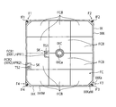
- FIG. 3 is a top view showing an example of a state where the heat radiation pad HP and the ferrite core FC are housed on the upper surface of the inner case IX shown in FIG.
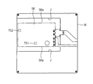
- FIG. 4 is a bottom view showing an example of a state where the control board SK is arranged on the lower side of the inner case IX shown in FIG.
- FIG. 1 is a diagram showing an example of a configuration of a charging system 1000 including a resonator device 100 according to the present invention.
- FIG. 2 is a developed view showing an example of the configuration of the power receiving resonator device (vehicle-side resonator device) 100 shown in FIG.
- FIG. 3 is a top
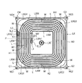
- FIG. 5 is a bottom view showing an example of a state where the coil L is housed in the housing groove LXM on the lower surface of the coil case LX shown in FIG.
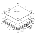
- FIG. 6 is a developed view showing a state where the inner case IX containing the heat radiation pad HP and the ferrite core FC, the insulating sheet, and the coil case LX containing the coil L are combined.
- FIG. 7 is a top view showing an example of a state in which the heat dissipation pad HP and the inner case IX accommodating the ferrite core FC shown in FIG. 6, the insulating sheet, and the coil case LX accommodating the coil L are combined.
- FIG. 8 is a cross-sectional view showing an example of a cross section taken along line AA of FIG.
- FIG. 9 is a cross-sectional view showing an example of a cross section taken along line BB of FIG.
- FIG. 10 is a cross-sectional view showing an example of a cross section taken along line CC of FIG.
- FIG. 1 is a diagram showing an example of the configuration of a charging system 1000 including the resonator device 100 according to the present invention.
- a charging system 1000 includes a distribution board D, a ground-side charging device GC, a power transmitting resonator device (ground-side resonator device) 200, and a vehicle-side charging device VC. , A power receiving resonator device (vehicle-side resonator device) 100, and an electric vehicle V.
- the electric vehicle V includes, for example, a battery X for charging power for driving the electric vehicle V, a vehicle-side charging device VC, and a power-receiving resonator device 100, as shown in FIG. ing.
- the distribution board D supplies the power supplied from the external power system to the ground-side charging device GC, for example, as shown in FIG.
- the ground-side charging device GC is arranged on the ground side, for example, as shown in FIG.
- the ground-side charging device GC communicates with the vehicle-side charging device VC to execute wireless charging of the battery X, for example, as shown in FIG.
- the ground-side charging device GC includes, for example, a wireless module (not shown) for communicating with the vehicle-side charging device VC, a power supply circuit that receives power from the distribution board D to generate power, and an inverter that converts power. And a controller for controlling the wireless module, the power supply circuit, and the inverter.
- the power transmitting resonator device 200 is installed on the ground, for example, as shown in FIG.
- the power transmitting resonator device 200 is used for wireless charging of the battery X.
- the power transmitting resonator device 200 is controlled by a ground-side charging device GC.
- a power transmitting coil and a control unit (control board) that controls magnetic resonance transmission using the coil are provided. , Is provided.
- the power receiving resonator device 100 is mounted on the electric vehicle V (fixed to a fixing member 100A below the electric vehicle V).
- the power receiving resonator device 100 is mounted on the electric vehicle V and is used for wireless charging of the battery X for driving the electric vehicle V.
- the power receiving resonator device 100 is controlled by a vehicle-side charging device VC.
- a vehicle-side charging device VC For example, a power receiving coil and a control unit (control board) that controls magnetic resonance transmission using the coil. And.
- FIG. 2 is a developed view showing an example of the configuration of the power receiving resonator device (vehicle-side resonator device) 100 shown in FIG.
- FIG. 3 is a top view showing an example of a state where the heat radiation pad HP and the ferrite core FC are housed on the upper surface of the inner case IX shown in FIG.
- FIG. 4 is a bottom view showing an example of a state in which the control board SK is arranged on the lower side of the inner case IX shown in FIG.
- FIG. 5 is a bottom view showing an example of a state where the coil L is housed in the housing groove LXM on the lower surface of the coil case LX shown in FIG.
- FIG. 6 is a development view showing a state where the inner case IX containing the heat radiation pad HP and the ferrite core FC, the insulating sheet, and the coil case LX containing the coil L are combined.
- FIG. 7 is a top view showing an example of a state where the heat dissipation pad HP and the inner case IX accommodating the ferrite core FC shown in FIG. 6, the insulating sheet, and the coil case LX accommodating the coil L are combined. .
- FIG. 8 is a cross-sectional view showing an example of a cross section taken along line AA of FIG.
- FIG. 9 is a sectional view showing an example of a section taken along line BB of FIG.
- FIG. 10 is a sectional view showing an example of a section taken along line CC of FIG.
- the power receiving resonator device 100 mounted on the electric vehicle V is used for wireless charging of a battery mounted on the electric vehicle and driving the electric vehicle.
- the resonator device 100 includes, for example, as shown in FIG. 2, a cover case CX, a metal base plate AB, a power transmission coil L, a coil case LX, a ferrite core FC, an inner case IX, A control board SK, an insulating sheet IS, and a heat radiation pad HP are provided.
- the metal base plate AB is a non-magnetic metal plate whose lower surface is fixed to the fixing member 100A (FIG. 1) of the electric vehicle V.
- the metal base plate AB is made of aluminum.
- a sealing groove ABM1 extending along the periphery is formed.
- the cover case CX is arranged so as to cover the upper surface of the metal base plate AB, for example, as shown in FIG.
- the cover case CX forms a storage space Z between the cover case CX and the metal base plate AB, for example, as shown in FIG. That is, the storage space Z is a space surrounded by the cover case CX and the metal base plate AB.
- a portion of the cover case CX that is in contact with the metal base plate AB is a projection that is fitted to the sealing groove ABM1 formed in the metal base plate AB while being arranged to cover the upper surface of the metal base plate AB. A part is formed. Then, the protrusion is fitted into the sealing groove ABM1 to which the liquid packing has been applied.
- the cover case CX is made of, for example, a thermosetting resin (for example, an unsaturated polyester resin).
- the coil L is disposed in a storage space Z composed of a cover case CX and a metal base plate AB.
- the coil L has one end L1 connected to the first coil terminal TL1, and the other end L2 connected to the second coil terminal TL2.
- the coil case LX is arranged in a storage space Z formed by a cover case CX and a metal base plate AB, for example, as shown in FIG. .
- a storage groove LXM is formed in the coil case LX so as to be wound around the center of the lower surface.
- a first terminal arrangement area LXH1 for accommodating the first coil terminal TL1 is formed at one end located at the most central side of the wound storage groove LXM.
- the first terminal arrangement region LXH1 is formed, for example, so that the first coil terminal TL1 can be screwed to the first control terminal TS1 of the control board SK located below the coil case LX from above the coil case LX.
- the coil case LX penetrates vertically.
- a second terminal arrangement area LXH2 for accommodating the second coil terminal TL2 is formed at the other end located on the outermost side of the storage groove LXM around which the bill is wound.
- the second terminal arrangement area LXH2 is formed, for example, so that the second coil terminal TL2 can be screwed to the second control terminal TS2 of the control board SK located below the coil case LX from above the coil case LX.
- the coil case LX penetrates vertically.
- the first terminal arrangement area LXH1 and the second terminal arrangement area LXH2 are arranged close to each other on the first side H1 side of the coil case LX.
- the widths HY1 and HY2 of the first terminal arrangement area LXH1 and the second terminal arrangement area LXH2 are set to be larger than the width MY of the storage groove LXM.
- the storage groove LXM stores the coil L so that the other end L2 of the coil L extends along the first side H1 of the coil case LX, and also stores the coil case.
- the coil L is housed such that a straight line P orthogonal to the first side H1 on the lower surface of the LX passes through one end L1 of the coil L and the other end L2 of the coil L.
- the coil case LX accommodates the coil L spirally in the accommodation groove LXM.
- the coil case LX is made of, for example, a resin containing glass fiber.
- the resin forming the coil case LX is a thermosetting resin containing glass fibers or a thermoplastic resin containing glass fibers.
- thermosetting resin is, for example, an unsaturated polyester resin.
- thermoplastic resin is, for example, polyphenylene sulfide (PPS) resin.
- the ferrite core FC is disposed in a storage space Z formed by the cover case CX and the metal base plate AB, and is disposed on the upper surface of the inner case IX via the heat radiation pad HP. Are located.
- the ferrite core FC is arranged in the storage space Z such that the upper surface of the ferrite core FC is adjacent to the lower surface of the coil case LX.
- the ferrite core FC is disposed in the storage space Z formed by the cover case CX and the metal base plate AB so as to face the coil L.
- the ferrite core FC is composed of, for example, a plurality of ferrite plates FCB arranged adjacently on the upper surface of the inner case IX as shown in FIG.
- the plurality of ferrite plates FCB are covered with an insulating tape (for example, a polyimide tape) at each periphery (ends adjacent to each other).
- an insulating tape for example, a polyimide tape
- the heat radiation pad HP is disposed in the storage space Z and is located between the ferrite core FC and the inner case IX.
- the heat radiation pad HP is made of silicon.
- the inner case IX is disposed between the metal base plate AB and the coil case LX in a storage space Z formed by the cover case CX and the metal base plate AB, for example, as shown in FIG. ing.
- the inner case IX has a ferrite core housed in the upper surface and a control board SK arranged in the lower surface.
- the inner case IX is made of, for example, a thermosetting resin (for example, an unsaturated polyester resin) or a thermoplastic resin (for example, polyphenylene sulfide (PPS) resin).
- a thermosetting resin for example, an unsaturated polyester resin
- a thermoplastic resin for example, polyphenylene sulfide (PPS) resin
- This inner case IX has, for example, as shown in FIGS. 3 and 6, walls IXK and IXKa provided around the upper surface.
- the inner case IX accommodates and fixes the ferrite core FC in a region surrounded by walls IXK and IXKa on the upper surface so as to face the coil L.
- the inner case IX has a control board SK disposed on the lower surface thereof.
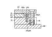
- an insulating groove IXKM which is recessed downward from the upper surface of the wall IXK, is formed in the upper part of the wall IXK of the inner case IX along the direction in which the wall IXK extends (FIG. 6). 8).
- the height of the upper surface of the wall portion IXK of the inner case IX is, for example, higher than the height of the upper surface of the ferrite core FC, as shown in FIG.
- the insulating groove IXKM recessed downward from the upper surface of the wall ISK is formed in the upper part of the wall IXK of the inner case IX along the direction in which the wall IXK extends.
- the insulation distance (creepage distance) from the coil L to the metal base plate AB is reduced in the vicinity of the side between the four corners (first to fourth corners F1 to F4) of the inner case IX. It can be longer.
- the coil case LX is arranged in a region surrounded by a wall on the upper surface of the inner case IX such that the ferrite core FC and the coil L face each other via the insulating sheet IS. ing.
- first control terminal TS1 and the second control terminal TS2 of the control board SK are, for example, as shown in FIG. 3, via a first through hole IXR1 and a second through hole IXR2 penetrating the inner case IX in the vertical direction. And is exposed on the upper surface of the inner case IX.
- the first through hole FCR1 and the second through hole FCR2 of the ferrite core FC (the first through hole HPR1 and the second through hole HPR2 of the heat radiation pad HP, the first through hole of the inner case IX).
- the first coil terminal TL1 and the first control terminal TS1 are electrically connected through the port IXR1 and the second through-hole IXR2), and the second coil terminal TL2 and the second control terminal TS2 are electrically connected. ing.
- the insulating sheet IS is located between the lower surface of the coil case LX and the ferrite core FC in the storage space Z formed by the cover case CX and the metal base plate AB. ing.
- the insulating sheet IS covers the coil L on the lower surface of the coil case LX and has insulating properties.
- the control board SK is arranged on the lower surface side of the inner case IX, for example, as shown in FIG.
- the control board SK has, on its upper surface, a first control terminal TS1 to which the first coil terminal TL1 is electrically connected, and a second coil terminal TL2 to be electrically connected.
- a second control terminal TS2 is provided.
- FIG. 4 shows a portion of the control board SK that is exposed on the lower surface side of the first coil terminal TL1 and the second coil terminal TL2.
- the through holes ISR1, ISR2, FCR1, FCR2, HPR1, HPR2, IXR1, IXR2 are connected by screws (FIG. 7).
- the through holes ISR1, ISR2, FCR1, FCR2, HPR1, HPR2, IXR1, IXR2 may be connected by soldering or welding.
- a step J is formed on the lower surface of the inner case IX near the end SKa of the control board SK.
- the inner case IX and the coil case LX each have a rectangular (square) shape (FIGS. 2 to 7).
- four pedestals IF1, IF2, IF3, IF4 are provided at the four corners (first to fourth corners F1 to F4) of the inner case IX.
- a central pedestal portion IXC protruding upward from the central portion of the upper surface of the inner case IX is provided at the center of the upper surface of the inner case IX.
- a central support portion LXC protruding downward from the lower surface of the coil case LX is provided at the center of the lower surface of the coil case LX.
- the four support portions NG1, NG2, NG3, NG4 are fixed to the four pedestal portions IF1, IF2, IF3, IF4 in a one-to-one correspondence (for example, fixed by screws or the like), and the central support portion.
- the coil case LX is supported by the inner case IX by fixing the LXC to the center pedestal portion IXC (for example, by fixing it with an adhesive or the like) (FIG. 6).
- the distance between the upper surface of the inner case IX and the lower surface of the coil case LX is fixed at a preset distance. It will be.
- a concave portion IXCa having a step on the inner surface is formed on the upper surface of the central pedestal portion IXC of the inner case IX.
- the insulation distance (the creepage distance) from the coil L to the metal base plate AB can be increased.
- the plurality of ferrite plates FCB are formed on the upper surface of the inner case IX by the central pedestal portion IXC of the inner case IX and the wall portion IXK provided around the upper surface of the inner case IX. It is arranged side by side between.
- the height IXKah of the wall IXKa (the height from the upper surface of the metal base substrate AB in FIG. 10 to the upper surface of the wall IXKa) at the four corners of the inner case IX is The height of the wall portion IXK at the side between the four corners of the IX is lower than the height IXKh (height from the upper surface of the metal base substrate AB to the upper surface of the wall portion IXK in FIG. 8).
- the four support portions NG1 to NG4 at the four corners (first to fourth corners G1 to G4) of the coil case LX are respectively provided at the four corners (first to fourth corners) of the inner case IX.
- the fourth corner portions F1 to F4) are fixed to the four pedestal portions IF1 to IF4 of the inner case IX over the wall portion IXKa.
- projecting portions LXa projecting downward are provided near the four support portions NG1 to NG4 of the coil case LX, respectively, and the four corners (first to fourth corner portions F1 to F4) of the inner case IX are provided.
- the insulating grooves IXKaM recessed downward from the upper surface of the wall part IXKa at the four corners (first to fourth corners F1 to F4) of the inner case IX are formed. Are formed along the direction in which the wall portion IXKa extends (FIGS. 6 and 10).
- the protrusions LXa of the four support portions NG1 to NG4 of the coil case LX are inserted into the groove portions IXKaM of the wall portions IXKa at the four corners of the inner case IX, so that the creepage distance from the ferrite core FC to the metal base substrate AB is set in advance. The distance is fixed at the set distance.
- the center support portion LXC of the coil case LX has a through hole ISQ provided at the center of the insulating sheet IS, a through hole FCQ provided at the center of the ferrite core FC, and a through hole provided at the center of the heat radiation pad HP. Through the mouth HPQ (FIG. 2), it is fixed to the central base IXC of the inner case IX.
- the insulating groove IXKMa recessed downward from the upper surface of the wall ISKa is formed in the upper part of the wall IXKa of the inner case IX along the direction in which the wall IXK extends.
- the insulation distance (creep distance) from the coil L to the metal base plate AB can be increased in the vicinity of the four corners (first to fourth corners F1 to F4) of the inner case IX. Will be possible.
- the insulating grooves IXKM and IXKaM recessed downward from the upper surfaces of the walls ISK and IXKa are provided above the walls IXK and IXKa of the inner case IX.
- IXK, IXKa are formed along the extending direction.
- the concave portion IXCa on the upper surface of the central pedestal portion IXC of the inner case IX and the central support portion LXC protruding downward from the lower surface of the coil case LX are fitted.
- the insulation distance (the creepage distance) from the coil L to the metal base plate AB can be increased.
- the insulation between the coil L and the metal base plate AB fixed to the fixing member of the electric vehicle V can be improved (that is, the number of insulating materials and members can be reduced). it can.
- the example of the power receiving resonator device 100 mounted on the electric vehicle and used for wireless charging of the battery for driving the electric vehicle and mounted on the electric vehicle has been described.
- the present invention can be applied to a power transmission resonator device 200 mounted on an electric vehicle and used for wireless charging of a battery for driving the electric vehicle, and installed on the ground.
- the coil of the power receiving resonator device 100 corresponds to the coil of the power transmitting resonator device 200.
- the resonator device is used for wireless charging of a battery mounted on an electric vehicle and driving the electric vehicle, and used for power reception or on the ground mounted on the electric vehicle.
- a resonator device for power transmission to be installed wherein a coil L whose one end L1 is connected to a first coil terminal TL1 and whose other end L2 is connected to a second coil terminal TL2, and a coil L which is housed on a lower surface.
- a control board SK provided with control terminals and a wall K provided around the upper surface and disposed between the metal base plate and the coil case.
- An insulating groove recessed downward from the upper surface of the wall is formed in the upper part of the wall of the inner case along the direction in which the wall extends.
- the insulation distance (creepage distance) from the coil to the metal base plate can be increased.
- the insulation between the coil and the metal base plate fixed to the fixing member of the electric vehicle can be improved (that is, the number of insulating materials and members can be reduced).
- Charging system 1000 D Distribution board GC Ground side charging device 200 Resonator device for power transmission (ground side resonator device) VC Vehicle-side charging device 100 Resonator device for receiving power (vehicle-side resonator device) V Electric car CX Cover case AB Metal base plate L Power transmission coil LX Coil case FC Ferrite core IX Inner case SK Control board IS Insulation sheet HP Heat radiation pad
Landscapes
- Engineering & Computer Science (AREA)
- Power Engineering (AREA)
- Computer Networks & Wireless Communication (AREA)
- Current-Collector Devices For Electrically Propelled Vehicles (AREA)
- Charge And Discharge Circuits For Batteries Or The Like (AREA)
Abstract
レゾネータ装置は、一端部に第1コイル端子が接続され且つ他端部に第2コイル端子が接続されたコイルと、下面にコイルを収納するコイルケースと、コイルと対向するように配置されるフェライトコアと、第1コイル端子が電気的に接続される第1制御端子と第2コイル端子が電気的に接続される第2制御端子とが設けられた制御基板と、金属ベース板とコイルケースとの間に配置されるとともに、上面の周囲に設けられた壁部を有し、コイルと対向するように上面の壁部で囲まれる領域にフェライトコアを収納し且つ固定し、さらに、下面に制御基板が配置されるインナーケースと、を備える。
Description
本発明は、レゾネータ装置に関する。
従来、電気自動車の非接触充電に用いるために車両側に搭載された受電側のアンテナとして、VA(Vehicle Assembly)レゾネータ装置が知られている(例えば、特開2018-29096参照)。
このような従来のレゾネータ装置は、例えば、電気自動車の固定部材に固定されるアルミ等の金属製のベース板と、このベース板上に配置されるとともに、複数の電子機器が設けられた基板と、この基板上に配置される支持板と、この支持板上に配置されるフェライト板と、このフェライト板上に配置されたコイルと、コイルを収容するコイルケースと、ベース板を覆う蓋と、を備える。
しかしながら、従来のレゾネータ装置では、コイルを収納するコイルケースと、金属製のベース板とがネジにより直接接続されている。すなわち、コイルから金属製のベース板までの絶縁距離(沿面距離)が短くなる。
したがって、従来のレゾネータ装置では、コイルと電気自動車の固定部材に固定される金属製のベース板との間の絶縁性を向上することが困難(すなわち、絶縁性の材料や部材を削減することが困難)であった。
そこで、本発明は、コイルと電気自動車の固定部材に固定される金属ベース板との間の絶縁性を向上する(すなわち、絶縁性の材料や部材を削減する)ことが可能なレゾネータ装置を提供することを目的とする。
本発明の一態様に係る実施形態に従ったレゾネータ装置は、
電気自動車に積載され且つ当該電気自動車を駆動するためのバッテリのワイヤレス充電に用いられ、当該電気自動車に積載される受電用又は地上に設置される送電用の、レゾネータ装置であって、
一端部に第1コイル端子が接続され且つ他端部に第2コイル端子が接続されたコイルと、
下面に前記コイルを収納するコイルケースと、
前記コイルと対向するように配置されるフェライトコアと、
前記第1コイル端子が電気的に接続される第1制御端子と前記第2コイル端子が電気的に接続される第2制御端子とが設けられた制御基板と、
前記金属ベース板と前記コイルケースとの間に配置されるとともに、上面の周囲に設けられた壁部を有し、前記コイルと対向するように前記上面の前記壁部で囲まれる領域に前記フェライトコアを収納し且つ固定し、さらに、下面に制御基板が配置されるインナーケースと、を備え、
前記インナーケースの前記壁部の上部には、前記壁部の上面から下方に凹んだ絶縁用溝部が、前記壁部が延在する方向に沿って形成されている
ことを特徴とする。
電気自動車に積載され且つ当該電気自動車を駆動するためのバッテリのワイヤレス充電に用いられ、当該電気自動車に積載される受電用又は地上に設置される送電用の、レゾネータ装置であって、
一端部に第1コイル端子が接続され且つ他端部に第2コイル端子が接続されたコイルと、
下面に前記コイルを収納するコイルケースと、
前記コイルと対向するように配置されるフェライトコアと、
前記第1コイル端子が電気的に接続される第1制御端子と前記第2コイル端子が電気的に接続される第2制御端子とが設けられた制御基板と、
前記金属ベース板と前記コイルケースとの間に配置されるとともに、上面の周囲に設けられた壁部を有し、前記コイルと対向するように前記上面の前記壁部で囲まれる領域に前記フェライトコアを収納し且つ固定し、さらに、下面に制御基板が配置されるインナーケースと、を備え、
前記インナーケースの前記壁部の上部には、前記壁部の上面から下方に凹んだ絶縁用溝部が、前記壁部が延在する方向に沿って形成されている
ことを特徴とする。
前記レゾネータ装置において、
下面側が前記電気自動車の固定部材に固定されるようになっている金属ベース板と、
前記金属ベース板の上面を覆うように配置され、前記金属ベース板との間に収納空間を構成するカバーケースと、をさらに備え、
前記コイル、前記コイルケース、前記フェライトコア、前記インナーケース、及び、前記制御基板は、前記収納空間内に配置されている
ことを特徴とする。
下面側が前記電気自動車の固定部材に固定されるようになっている金属ベース板と、
前記金属ベース板の上面を覆うように配置され、前記金属ベース板との間に収納空間を構成するカバーケースと、をさらに備え、
前記コイル、前記コイルケース、前記フェライトコア、前記インナーケース、及び、前記制御基板は、前記収納空間内に配置されている
ことを特徴とする。
前記レゾネータ装置において、
前記収納空間内で、前記コイルケースの下面と前記フェライトコアの上面との間に位置して前記コイルケースの下面で前記コイルを被覆するとともに、絶縁性を有する絶縁シートをさらに備える
ことを特徴とする。
前記収納空間内で、前記コイルケースの下面と前記フェライトコアの上面との間に位置して前記コイルケースの下面で前記コイルを被覆するとともに、絶縁性を有する絶縁シートをさらに備える
ことを特徴とする。
前記レゾネータ装置において、
前記壁部の上面の高さは、前記フェライトコアの上面の高さよりも高くなっていることを特徴とする。
前記壁部の上面の高さは、前記フェライトコアの上面の高さよりも高くなっていることを特徴とする。
前記レゾネータ装置において、
前記コイルケースは、前記絶縁シートを介して前記フェライトコアと前記コイルとが対向するように、前記インナーケースの上面の前記壁部で囲まれる領域に配置される
ことを特徴とする。
前記コイルケースは、前記絶縁シートを介して前記フェライトコアと前記コイルとが対向するように、前記インナーケースの上面の前記壁部で囲まれる領域に配置される
ことを特徴とする。
前記レゾネータ装置において、
前記制御基板の前記第1制御端子及び前記第2制御端子は、前記インナーケースを上下方向に貫通する第1貫通口及び第2貫通口を介して、前記インナーケースの上面にそれぞれ露出し、前記インナーケースの上面の近傍において、前記第1コイル端子と前記第1制御端子とが電気的に接続され、前記第2コイル端子と前記第2制御端子とが電気的に接続されている
ことを特徴とする。
前記制御基板の前記第1制御端子及び前記第2制御端子は、前記インナーケースを上下方向に貫通する第1貫通口及び第2貫通口を介して、前記インナーケースの上面にそれぞれ露出し、前記インナーケースの上面の近傍において、前記第1コイル端子と前記第1制御端子とが電気的に接続され、前記第2コイル端子と前記第2制御端子とが電気的に接続されている
ことを特徴とする。
前記レゾネータ装置において、
前記コイルケースの下面の中心部には、前記コイルケースの下面から下方に突出した中央支持部が設けられ、
前記インナーケースの上面の中心部には、前記インナーケースの上面の中心部から上方に突出した中央台座部が設けられ、
前記中央支持部が前記中央台座部に固定されることにより、前記インナーケースの上面と前記コイルケースの下面との間隔が予め設定された距離に固定される
ことを特徴とする。
前記コイルケースの下面の中心部には、前記コイルケースの下面から下方に突出した中央支持部が設けられ、
前記インナーケースの上面の中心部には、前記インナーケースの上面の中心部から上方に突出した中央台座部が設けられ、
前記中央支持部が前記中央台座部に固定されることにより、前記インナーケースの上面と前記コイルケースの下面との間隔が予め設定された距離に固定される
ことを特徴とする。
前記レゾネータ装置において、
前記インナーケースの中央台座部の上面には、その内面に段差を有する凹部が形成されている
ことを特徴とする。
前記インナーケースの中央台座部の上面には、その内面に段差を有する凹部が形成されている
ことを特徴とする。
前記レゾネータ装置において、
前記インナーケースの下面には、前記制御基板の端部の近傍において、段差が形成されている
ことを特徴とする。
前記インナーケースの下面には、前記制御基板の端部の近傍において、段差が形成されている
ことを特徴とする。
前記レゾネータ装置において、
前記フェライトコアは、前記インナーケースの上面上に隣接して配置された複数のフェライト板により構成されている
ことを特徴とする。
前記フェライトコアは、前記インナーケースの上面上に隣接して配置された複数のフェライト板により構成されている
ことを特徴とする。
前記レゾネータ装置において、
前記複数のフェライト板は、前記インナーケースの上面において、前記インナーケースの前記中央台座部と前記インナーケースの上面の周囲に設けられた前記壁部との間に並んで配置されている
ことを特徴とする。
前記複数のフェライト板は、前記インナーケースの上面において、前記インナーケースの前記中央台座部と前記インナーケースの上面の周囲に設けられた前記壁部との間に並んで配置されている
ことを特徴とする。
前記レゾネータ装置において、
前記インナーケース及び前記コイルケースは、それぞれ矩形の形状を有し、
前記コイルケースの四隅には、4つの支持部が設けられ、
前記インナーケースの四隅には、4つの台座部が設けられ、
前記コイルケースの下面の中心部には、前記コイルケースの下面から下方に突出した中央支持部が設けられ、
前記インナーケースの上面の中心部には、前記インナーケースの上面の中心部から上方に突出した中央台座部が設けられ、
前記4つの支持部が、一対一に対応して、前記4つの台座部に固定されるとともに、前記中央支持部が前記中央台座部に固定されることで、前記コイルケースが前記インナーケースに支持される
ことを特徴とする。
前記インナーケース及び前記コイルケースは、それぞれ矩形の形状を有し、
前記コイルケースの四隅には、4つの支持部が設けられ、
前記インナーケースの四隅には、4つの台座部が設けられ、
前記コイルケースの下面の中心部には、前記コイルケースの下面から下方に突出した中央支持部が設けられ、
前記インナーケースの上面の中心部には、前記インナーケースの上面の中心部から上方に突出した中央台座部が設けられ、
前記4つの支持部が、一対一に対応して、前記4つの台座部に固定されるとともに、前記中央支持部が前記中央台座部に固定されることで、前記コイルケースが前記インナーケースに支持される
ことを特徴とする。
前記レゾネータ装置において、
前記インナーケースの四隅における前記壁部の高さは、前記インナーケースの四隅の間の辺における前記壁部の高さよりも低くなっており、前記コイルケースの四隅の前記4つの支持部は、それぞれ、前記インナーケースの四隅における前記壁部上を跨いで、前記インナーケースの前記4つの台座部に固定されている
ことを特徴とする。
前記インナーケースの四隅における前記壁部の高さは、前記インナーケースの四隅の間の辺における前記壁部の高さよりも低くなっており、前記コイルケースの四隅の前記4つの支持部は、それぞれ、前記インナーケースの四隅における前記壁部上を跨いで、前記インナーケースの前記4つの台座部に固定されている
ことを特徴とする。
前記レゾネータ装置において、
前記インナーケースは、熱硬化性樹脂、又は、熱可塑性樹脂で構成されている
ことを特徴とする。
前記インナーケースは、熱硬化性樹脂、又は、熱可塑性樹脂で構成されている
ことを特徴とする。
前記レゾネータ装置において、
前記複数のフェライト板は、それぞれの周囲が絶縁性のテープで被覆されている
ことを特徴とする。
前記複数のフェライト板は、それぞれの周囲が絶縁性のテープで被覆されている
ことを特徴とする。
前記レゾネータ装置において、
前記中央支持部は、前記絶縁シートに設けられた貫通口を介して、前記中央台座部に固定される
ことを特徴とする。
前記中央支持部は、前記絶縁シートに設けられた貫通口を介して、前記中央台座部に固定される
ことを特徴とする。
前記レゾネータ装置において、
前記コイルケースの前記4つの支持部の近傍には、それぞれ下方に突出する突出部が設けられ、
前記インナーケースの四隅における壁部の上部には、前記インナーケースの四隅における前記壁部の上面から下方に凹んだ絶縁用溝部が、前記インナーケースの四隅における前記壁部が延在する方向に沿って形成されており、
前記コイルケースの前記4つの支持部の突出部が前記インナーケースの四隅における前記壁部の前記絶縁用溝部に挿入されることにより、前記フェライトコアから前記金属ベース基板までの沿面距離が予め設定された距離に固定される
ことを特徴とする。
前記コイルケースの前記4つの支持部の近傍には、それぞれ下方に突出する突出部が設けられ、
前記インナーケースの四隅における壁部の上部には、前記インナーケースの四隅における前記壁部の上面から下方に凹んだ絶縁用溝部が、前記インナーケースの四隅における前記壁部が延在する方向に沿って形成されており、
前記コイルケースの前記4つの支持部の突出部が前記インナーケースの四隅における前記壁部の前記絶縁用溝部に挿入されることにより、前記フェライトコアから前記金属ベース基板までの沿面距離が予め設定された距離に固定される
ことを特徴とする。
前記レゾネータ装置において、
前記カバーケースは、熱硬化性樹脂で構成されていることを特徴とする。
前記カバーケースは、熱硬化性樹脂で構成されていることを特徴とする。
前記レゾネータ装置において、
前記コイルケースは、ガラス繊維を含有する樹脂で構成されていることを特徴とする。
前記コイルケースは、ガラス繊維を含有する樹脂で構成されていることを特徴とする。
本発明の一態様に係るレゾネータ装置は、電気自動車に積載され且つ当該電気自動車を駆動するためのバッテリのワイヤレス充電に用いられ、当該電気自動車に積載される受電用又は地上に設置される送電用の、レゾネータ装置であって、一端部に第1コイル端子が接続され且つ他端部に第2コイル端子が接続されたコイルと、下面にコイルLを収納するコイルケースと、コイルと対向するように配置されるフェライトコアと、第1コイル端子が電気的に接続される第1制御端子と第2コイル端子が電気的に接続される第2制御端子とが設けられた制御基板と、金属ベース板とコイルケースとの間に配置されるとともに、上面の周囲に設けられた壁部を有し、コイルと対向するように上面の壁部で囲まれる領域にフェライトコアを収納し且つ固定し、さらに、下面に制御基板が配置されるインナーケースと、を備える。
そして、インナーケースの壁部の上部には、壁部の上面から下方に凹んだ絶縁用溝部が、壁部が延在する方向に沿って形成されている。
これにより、本発明のレゾネータ装置では、コイルから金属ベース板までの絶縁距離(沿面距離)を長くすることが可能になる。
すなわち、本発明のレゾネータ装置によれば、コイルと電気自動車の固定部材に固定される金属ベース板との間の絶縁性を向上する(すなわち、絶縁性の材料や部材を削減する)ことができる。
以下、本発明に係る実施形態について図面に基づいて説明する。
本実施例1では、電気自動車に積載され且つ当該電気自動車を駆動するためのバッテリのワイヤレス充電に用いられ、当該電気自動車に積載される受電用のレゾネータ装置の例を説明する。
図1は、本発明に係るレゾネータ装置100を含む充電システムの1000の構成の一例を示す図である。
本発明に係る充電システム1000は、例えば、図1に示すように、分電盤Dと、地上側充電装置GCと、送電用のレゾネータ装置(地上側レゾネータ装置)200と、車両側充電装置VCと、受電用のレゾネータ装置(車両側レゾネータ装置)100と、電気自動車Vと、を備える。
そして、電気自動車Vは、例えば、図1に示すように、当該電気自動車Vを駆動するため電力を充電するバッテリXと、車両側充電装置VCと、受電用のレゾネータ装置100と、を積載している。
また、分電盤Dは、例えば、図1に示すように、外部の電力系統から供給された電力を、地上側充電装置GCに供給するようになっている。
そして、地上側充電装置GCは、例えば、図1に示すように、地上側に配置され、分電盤Dから必要な電力が供給されるようになっている。
この地上側充電装置GCは、例えば、図1に示すように、車両側充電装置VCと通信して、バッテリXのワイヤレス充電を実行するようになっている。
この地上側充電装置GCは、例えば、図示しない、車両側充電装置VCと通信するための無線モジュールと、分電盤Dから電力が供給され電源を生成する電源回路と、電力を変換するインバータと、これらの無線モジュール、電源回路、及びインバータを制御するコントローラと、を備える。
また、送電用のレゾネータ装置200は、例えば、図1に示すように、地上に設置されている。この送電用のレゾネータ装置200は、バッテリXのワイヤレス充電に用いられるようになっている。
この送電用のレゾネータ装置200は、地上側充電装置GCにより制御されるようになっており、例えば、送電用のコイルと、当該コイルを用いた磁気共鳴伝達を制御する制御部(制御基板)と、を備える。
また、受電用のレゾネータ装置100は、当該電気自動車Vに積載(電気自動車Vの下部の固定部材100Aに固定)されている。
そして、この受電用のレゾネータ装置100は、電気自動車Vに積載され且つ当該電気自動車Vを駆動するためのバッテリXのワイヤレス充電に用いられるようになっている。
さらに、この受電用のレゾネータ装置100は、車両側充電装置VCにより制御されるようになっており、例えば、受用のコイルと、当該コイルを用いた磁気共鳴伝達を制御する制御部(制御基板)と、を備える。
ここで、図2は、図1に示す受電用のレゾネータ装置(車両側レゾネータ装置)100の構成の一例を示す展開図である。また、図3は、図2に示すインナーケースIXの上面に放熱パッドHPとフェライトコアFCを収納した状態の一例を示す上面図である。また、図4は、図2に示すインナーケースIXの下面側に制御基板SKを配置した状態の一例を示す下面図である。また、図5は、図2に示すコイルケースLXの下面の収納溝LXMにコイルLを収納した状態の一例を示す下面図である。また、図6は、放熱パッドHPとフェライトコアFCを収納したインナーケースIXと、絶縁シートと、コイルLを収納したコイルケースLXとを組み合わせる状態の展開図である。また、図7は、図6に示す放熱パッドHPとフェライトコアFCを収納したインナーケースIXと、絶縁シートと、コイルLを収納したコイルケースLXとを組み合わせた状態の一例を示す上面図である。また、図8は、図7のA-A線に沿った断面の一例を示す断面図である。また、図9は、図7のB-B線に沿った断面の一例を示す断面図である。また、図10は、図7のC-C線に沿った断面の一例を示す断面図である。
なお、図2において、当該レゾネータ装置100が電気自動車Vに積載される場合には、上下方向が逆になっている。さらに、図2において、各部品を係止するためのネジ等は省略されている。
既述のように、電気自動車Vに積載される受電用のレゾネータ装置100は、当該電気自動車に積載され且つ当該電気自動車を駆動するためのバッテリのワイヤレス充電に用いられるようになっている。
そして、このレゾネータ装置100は、例えば、図2に示すように、カバーケースCXと、金属ベース板ABと、送電用のコイルLと、コイルケースLXと、フェライトコアFCと、インナーケースIXと、制御基板SKと、絶縁シートISと、放熱パッドHPと、を備える。
そして、金属ベース板ABは、下面側が電気自動車Vの固定部材100A(図1)に固定されるようになっている非磁性の金属板である。
例えば、この金属ベース板ABは、アルミで構成されている。
ここで、既述の金属ベース板ABは、例えば、図1、図6、図7に示すように、周辺に沿って延在する封止用溝ABM1が形成されている。
また、カバーケースCXは、例えば、図2に示すように、金属ベース板ABの上面を覆うように配置されている。
このカバーケースCXは、例えば、図2に示すように、金属ベース板ABとの間に収納空間Zを構成するようになっている。すなわち、当該収納空間Zは、カバーケースCXと金属ベース板ABにより囲まれた空間である。
そして、カバーケースCXのうちの金属ベース板ABと接する部分には、金属ベース板の上面を覆うように配置された状態で、金属ベース板ABに形成された封止用溝ABM1に嵌め込まれる突起部が形成されている。そして、当該突起部が、液体パッキンが塗布された封止用溝ABM1に嵌め込まれる。
なお、このカバーケースCXは、例えば、熱硬化性樹脂(例えば、不飽和ポリエステル樹脂)で構成されている。
また、コイルLは、例えば、図2に示すように、カバーケースCXと金属ベース板ABとのより構成される収納空間Zに配置されている。
このコイルLは、一端部L1に第1コイル端子TL1が接続され、他端部L2に第2コイル端子TL2が接続されている。
また、コイルケースLXは、例えば、図2に示すように、カバーケースCXと金属ベース板ABとのより構成される収納空間Z内に配置され、下面にコイルLを収納するようになっている。
このコイルケースLXは、下面の中心部を取り囲んで巻回するように収納溝LXMが形成されている。
そして、このコイルケースLXは、巻回された収納溝LXMの最も中心部側に位置する一端部に、第1コイル端子TL1を収納する第1端子配置領域LXH1が形成されている。
なお、この第1端子配置領域LXH1は、例えば、コイルケースLXの上方から第1コイル端子TL1を、コイルケースLXの下方に位置する制御基板SKの第1制御端子TS1にネジ止めできるように、コイルケースLXを上下方向に貫通している。
さらに、このコイルケースLXは、券回された収納溝LXMの最も外側に位置する他端部に、第2コイル端子TL2を収納する第2端子配置領域LXH2が形成されている。
なお、この第2端子配置領域LXH2は、例えば、コイルケースLXの上方から第2コイル端子TL2を、コイルケースLXの下方に位置する制御基板SKの第2制御端子TS2にネジ止めできるように、コイルケースLXを上下方向に貫通している。
なお、例えば、図5に示すように、第1端子配置領域LXH1と第2端子配置領域LXH2とは、コイルケースLXの第1辺H1側において近接して配置されている。
また、例えば、図5に示すように、第1端子配置領域LXH1及び第2端子配置領域LXH2の幅HY1、HY2は、収納溝LXMの幅MYよりも大きくなるように設定されている。
また、例えば、図5に示すように、収納溝LXMは、コイルLの他端部L2がコイルケースLXの第1辺H1に沿って延在するように、コイルLを収納するとともに、コイルケースLXの下面上で第1辺H1に直交する直線Pが、コイルLの一端部L1およびコイルLの他端部L2を通過するように、コイルLを収納するようになっている。
そして、このコイルケースLXは、コイルLを渦巻き状に収納溝LXMに収納するようになっている。
なお、コイルケースLXは、例えば、ガラス繊維を含有する樹脂で構成されている。
そして、このコイルケースLXを構成する樹脂は、ガラス繊維を含有する熱硬化性樹脂、又は、ガラス繊維を含有する熱可塑性樹脂である。
特に、当該熱硬化性樹脂は、例えば、不飽和ポリエステル樹脂である。また、熱可塑性樹脂は、例えば、ポリフェニレンサルファイド(PPS)樹脂)である。
また、フェライトコアFCは、例えば、図2に示すように、カバーケースCXと金属ベース板ABとのより構成される収納空間Zに配置され、放熱パッドHPを介して、インナーケースIXの上面に配置されている。
そして、このフェライトコアFCは、収納空間Zにおいて、当該フェライトコアFCの上面がコイルケースLXの下面と隣接するように配置されている。
すなわち、このフェライトコアFCは、例えば、図2に示すように、カバーケースCXと金属ベース板ABとのより構成される収納空間Z内に、コイルLと対向するように配置されている。
また、フェライトコアFCは、例えば、図3に示すように、インナーケースIXの上面上に隣接して配置された複数のフェライト板FCBにより構成されている。
この複数のフェライト板FCBは、それぞれの周囲(それぞれが互いに隣接する端部)が絶縁性のテープ(例えば、ポリイミドテープ)で被覆されている。
また、放熱パッドHPは、例えば、図2に示すように、収納空間Z内に配置され、フェライトコアFCとインナーケースIXとの間に位置するようになっている。
この放熱パッドHPは、シリコンで構成されている。
また、インナーケースIXは、例えば、図2に示すように、カバーケースCXと金属ベース板ABとのより構成される収納空間Z内で、金属ベース板ABとコイルケースLXとの間に配置されている。
そして、このインナーケースIXは、上面にフェライトコアを収納し、下面に制御基板SKが配置されている。
このインナーケースIXは、例えば、熱硬化性樹脂(例えば、不飽和ポリエステル樹脂)、又は、熱可塑性樹脂(例えば、ポリフェニレンサルファイド(PPS)樹脂)で構成されている。
このインナーケースIXは、例えば、図3、図6に示すように、上面の周囲に設けられた壁部IXK、IXKaを有する。そして、インナーケースIXは、コイルLと対向するように上面の壁部IXK、IXKaで囲まれる領域にフェライトコアFCを収納し且つ固定するようになっている。
さらに、インナーケースIXは、その下面に制御基板SKが配置されるようになっている。
また、このインナーケースIXの壁部IXKの上部には、当該壁部IXKの上面から下方に凹んだ絶縁用溝部IXKMが、壁部IXKが延在する方向に沿って形成されている(図6、図8)。
このインナーケースIXの壁部IXKの上面の高さは、例えば、図8に示すように、フェライトコアFCの上面の高さよりも高くなっている。
上述のように、インナーケースIXの壁部IXKの上部には、壁部ISKの上面から下方に凹んだ絶縁用溝部IXKMが、壁部IXKが延在する方向に沿って形成されている。
これにより、レゾネータ装置100では、インナーケースIXの四隅(第1~第4の角部F1~F4)の間の辺の近傍において、コイルLから金属ベース板ABまでの絶縁距離(沿面距離)を長くすることが可能になる。
また、例えば、図8に示すように、コイルケースLXは、絶縁シートISを介してフェライトコアFCとコイルLとが対向するように、インナーケースIXの上面の壁部で囲まれる領域に配置されている。
また、制御基板SKの第1制御端子TS1及び第2制御端子TS2は、例えば、図3に示すように、インナーケースIXを上下方向に貫通する第1貫通口IXR1及び第2貫通口IXR2を介して、インナーケースIXの上面にそれぞれ露出している。
そして、インナーケースIXの上面の近傍において、フェライトコアFCの第1貫通口FCR1及び第2貫通口FCR2(放熱パッドHPの第1貫通口HPR1及び第2貫通口HPR2、インナーケースIXの第1貫通口IXR1及び第2貫通口IXR2)を介して、第1コイル端子TL1と第1制御端子TS1とが電気的に接続され、第2コイル端子TL2と第2制御端子TS2とが電気的に接続されている。
また、絶縁シートISは、例えば、図2に示すように、カバーケースCXと金属ベース板ABとにより構成される収納空間Z内で、コイルケースLXの下面とフェライトコアFCとの間に位置している。
そして、この絶縁シートISは、コイルケースLXの下面においてコイルLを被覆するとともに、絶縁性を有する。
また、制御基板SKは、例えば、図4に示すように、インナーケースIXの下面側に配置されている。
そして、制御基板SKは、例えば、図3に示すように、その上面に、第1コイル端子TL1が電気的に接続される第1制御端子TS1、及び第2コイル端子TL2が電気的に接続される第2制御端子TS2が設けられている。
なお、図4では、制御基板SKの第1コイル端子TL1及び第2コイル端子TL2の下面側に露出した部分が示されている。
そして、第1コイル端子TL1と第1制御端子TS1との間、及び、第2コイル端子TL2と第2制御端子TS2との間は、絶縁シートIS、フェライトコアFC、及びインナーケースIXを貫通する各貫通口ISR1、ISR2、FCR1、FCR2、HPR1、HPR2、IXR1、IXR2を介して、ネジ止めにより接続されている(図7)。
なお、第1コイル端子TL1と第1制御端子TS1との間、及び、第2コイル端子TL2と第2制御端子TS2との間は、絶縁シートIS、フェライトコアFC、及びインナーケースIXを貫通する各貫通口ISR1、ISR2、FCR1、FCR2、HPR1、HPR2、IXR1、IXR2を介して、はんだ付け、又は溶接により接続されていてもよい。
また、例えば、図4に示すように、インナーケースIXの下面には、制御基板SKの端部SKaの近傍において、段差Jが形成されている。これにより、制御基板SKと金属ベース基板ABとの間の沿面距離を長くできるようになっている。
ここで、インナーケースIX及びコイルケースLXは、それぞれ矩形(四角形)の形状を有する(図2~図7)。
そして、例えば、図3に示すように、インナーケースIXの四隅(第1~第4の角部F1~F4)には、4つの台座部IF1、IF2、IF3、IF4が設けられている。
さらに、例えば、図3に示すように、インナーケースIXの上面の中心部には、インナーケースIXの上面の中心部から上方に突出した中央台座部IXCが設けられている。
そして、例えば、図5に示すように、コイルケースLXの四隅(第1~第4の角部G1~G4)には、4つの支持部NG1、NG2、NG3、NG4が設けられている。
さらに、例えば、図5に示すように、コイルケースLXの下面の中心部には、コイルケースLXの下面から下方に突出した中央支持部LXCが設けられている。
当該4つの支持部NG1、NG2、NG3、NG4が、一対一に対応して、4つの台座部IF1、IF2、IF3、IF4に固定(例えば、ネジ止め等により固定)されるとともに、中央支持部LXCが中央台座部IXCに固定(例えば、接着等により固定)されることで、コイルケースLXがインナーケースIXに支持されるようになっている(図6)。
特に、コイルケースLXの中央支持部LXCがインナーケースIXの中央台座部IXCに固定されることにより、インナーケースIXの上面とコイルケースLXの下面との間隔が予め設定された距離に固定されることとなる。
また、例えば、図3に示すように、インナーケースIXの中央台座部IXCの上面には、内面に段差を有する凹部IXCaが形成されている。
そして、このインナーケースIXの中央台座部IXCの上面の凹部IXCaと、コイルケースLXの下面から下方に突出した中央支持部LXCとが嵌合することで、より確実に所定の位置関係で固定できるようになっている(図9)。
これにより、レゾネータ装置100では、コイルLから金属ベース板ABまでの絶縁距離(沿面距離)を長くすることが可能になる。
そして、例えば、図3に示すように、複数のフェライト板FCBは、インナーケースIXの上面において、インナーケースIXの当該中央台座部IXCとインナーケースIXの上面の周囲に設けられた壁部IXKとの間に並んで配置されている。
また、例えば、図6に示すように、このインナーケースIXの四隅における壁部IXKaの高さIXKah(図10の金属ベース基板ABの上面から壁部IXKaの上面までの高さ)は、インナーケースIXの四隅の間の辺における壁部IXKの高さIXKh(図8の金属ベース基板ABの上面から壁部IXKの上面までの高さ)よりも低くなっている。
さらに、例えば、図10に示すように、コイルケースLXの四隅(第1~第4の角部G1~G4)の4つの支持部NG1~NG4は、それぞれ、インナーケースIXの四隅(第1~第4の角部F1~F4)における壁部IXKa上を跨いで、インナーケースIXの4つの台座部IF1~IF4に固定されるようになっている。
特に、コイルケースLXの4つの支持部NG1~NG4の近傍には、それぞれ下方に突出する突出部LXaが設けられており、インナーケースIXの四隅(第1~第4の角部F1~F4)における壁部IXKaの上部には、インナーケースIXの四隅(第1~第4の角部F1~F4)における当該壁部IXKaの上面から下方に凹んだ絶縁用溝部IXKaMが、インナーケースIXの四隅における壁部IXKaが延在する方向に沿って形成されている(図6、図10)。
当該コイルケースLXの4つの支持部NG1~NG4の突出部LXaがインナーケースIXの四隅における壁部IXKaの溝部IXKaMに挿入されることにより、フェライトコアFCから金属ベース基板ABまでの沿面距離が予め設定された距離に固定されることとなる。
なお、コイルケースLXの中央支持部LXCは、絶縁シートISの中央に設けられた貫通口ISQ、フェライトコアFCの中央に設けられた貫通口FCQ、及び、放熱パッドHPの中央に設けられた貫通口HPQを介して(図2)、インナーケースIXの中央台座部IXCに固定されるようになっている。
上述のように、インナーケースIXの壁部IXKaの上部には、壁部ISKaの上面から下方に凹んだ絶縁用溝部IXKMaが、壁部IXKが延在する方向に沿って形成されている。
これにより、レゾネータ装置100では、インナーケースIXの四隅(第1~第4の角部F1~F4)の近傍において、コイルLから金属ベース板ABまでの絶縁距離(沿面距離)を長くすることが可能になる。
以上のように、実施例1に係るレゾネータ装置100によれば、インナーケースIXの壁部IXK、IXKaの上部には、壁部ISK、IXKaの上面から下方に凹んだ絶縁用溝部IXKM、IXKaMが、壁部IXK、IXKaが延在する方向に沿って形成されている。さらに、インナーケースIXの中央台座部IXCの上面の凹部IXCaと、コイルケースLXの下面から下方に突出した中央支持部LXCとが嵌合する。
これにより、レゾネータ装置100では、コイルLから金属ベース板ABまでの絶縁距離(沿面距離)を長くすることが可能になる。
すなわち、レゾネータ装置100によれば、コイルLと電気自動車Vの固定部材に固定される金属ベース板ABとの間の絶縁性を向上する(すなわち、絶縁性の材料や部材を削減する)ことができる。
既述の実施例1では、電気自動車に積載され且つ当該電気自動車を駆動するためのバッテリのワイヤレス充電に用いられ、当該電気自動車に積載される受電用のレゾネータ装置100の例を説明した。
しかし、本発明は、電気自動車に積載され且つ当該電気自動車を駆動するためのバッテリのワイヤレス充電に用いられ、地上に設置される送電用のレゾネータ装置200にも、適用されることができる。この場合、受電用のレゾネータ装置100のコイルが、送電用のレゾネータ装置200のコイルに対応することとなる。
なお、この実施例2におけるその他のレゾネータ装置の構成は、実施例1と同様である。
以上のように、本発明の一態様に係るレゾネータ装置は、電気自動車に積載され且つ当該電気自動車を駆動するためのバッテリのワイヤレス充電に用いられ、当該電気自動車に積載される受電用又は地上に設置される送電用の、レゾネータ装置であって、一端部L1に第1コイル端子TL1が接続され且つ他端部L2に第2コイル端子TL2が接続されたコイルLと、下面にコイルLを収納するコイルケースLXと、コイルLと対向するように配置されるフェライトコアFCと、第1コイル端子が電気的に接続される第1制御端子と第2コイル端子が電気的に接続される第2制御端子とが設けられた制御基板SKと、金属ベース板とコイルケースとの間に配置されるとともに、上面の周囲に設けられた壁部Kを有し、コイルLと対向するように上面の壁部Kで囲まれる領域にフェライトコアを収納し且つ固定し、さらに、下面に制御基板SKが配置されるインナーケースIXと、を備える。
そして、インナーケースの壁部の上部には、壁部の上面から下方に凹んだ絶縁用溝部が、壁部が延在する方向に沿って形成されている。
これにより、本発明のレゾネータ装置では、コイルから金属ベース板までの絶縁距離(沿面距離)を長くすることが可能になる。
すなわち、本発明のレゾネータ装置によれば、コイルと電気自動車の固定部材に固定される金属ベース板との間の絶縁性を向上する(すなわち、絶縁性の材料や部材を削減する)ことができる。
本発明のいくつかの実施形態を説明したが、これらの実施形態は、例として提示したものであり、発明の範囲を限定することは意図していない。これら実施形態は、その他の様々な形態で実施されることが可能であり、発明の要旨を逸脱しない範囲で、種々の省略、置き換え、変更を行うことができる。これら実施形態やその変形は、発明の範囲や要旨に含まれると同様に、特許請求の範囲に記載された発明とその均等の範囲に含まれるものである。
充電システム1000
D 分電盤
GC 地上側充電装置
200 送電用のレゾネータ装置(地上側レゾネータ装置)
VC 車両側充電装置
100 受電用のレゾネータ装置(車両側レゾネータ装置)
V 電気自動車
CX カバーケース
AB 金属ベース板
L 送電用のコイル
LX コイルケース
FC フェライトコア
IX インナーケース
SK 制御基板
IS 絶縁シート
HP 放熱パッド
D 分電盤
GC 地上側充電装置
200 送電用のレゾネータ装置(地上側レゾネータ装置)
VC 車両側充電装置
100 受電用のレゾネータ装置(車両側レゾネータ装置)
V 電気自動車
CX カバーケース
AB 金属ベース板
L 送電用のコイル
LX コイルケース
FC フェライトコア
IX インナーケース
SK 制御基板
IS 絶縁シート
HP 放熱パッド
Claims (19)
- 電気自動車に積載され且つ当該電気自動車を駆動するためのバッテリのワイヤレス充電に用いられ、当該電気自動車に積載される受電用又は地上に設置される送電用の、レゾネータ装置であって、
一端部に第1コイル端子が接続され且つ他端部に第2コイル端子が接続されたコイルと、
下面に前記コイルを収納するコイルケースと、
前記コイルと対向するように配置されるフェライトコアと、
前記第1コイル端子が電気的に接続される第1制御端子と前記第2コイル端子が電気的に接続される第2制御端子とが設けられた制御基板と、
前記金属ベース板と前記コイルケースとの間に配置されるとともに、上面の周囲に設けられた壁部を有し、前記コイルと対向するように前記上面の前記壁部で囲まれる領域に前記フェライトコアを収納し且つ固定し、さらに、下面に制御基板が配置されるインナーケースと、を備え、
前記インナーケースの前記壁部の上部には、前記壁部の上面から下方に凹んだ絶縁用溝部が、前記壁部が延在する方向に沿って形成されている
ことを特徴とするレゾネータ装置。 - 下面側が前記電気自動車の固定部材に固定されるようになっている金属ベース板と、
前記金属ベース板の上面を覆うように配置され、前記金属ベース板との間に収納空間を構成するカバーケースと、をさらに備え、
前記コイル、前記コイルケース、前記フェライトコア、前記インナーケース、及び、前記制御基板は、前記収納空間内に配置されている
ことを特徴とする請求項1に記載のレゾネータ装置。 - 前記収納空間内で、前記コイルケースの下面と前記フェライトコアの上面との間に位置して前記コイルケースの下面で前記コイルを被覆するとともに、絶縁性を有する絶縁シートをさらに備える
ことを特徴とする請求項2に記載のレゾネータ装置。 - 前記壁部の上面の高さは、前記フェライトコアの上面の高さよりも高くなっていることを特徴とする請求項3に記載のレゾネータ装置。
- 前記コイルケースは、前記絶縁シートを介して前記フェライトコアと前記コイルとが対向するように、前記インナーケースの上面の前記壁部で囲まれる領域に配置される
ことを特徴とする請求項4に記載のレゾネータ装置。 - 前記制御基板の前記第1制御端子及び前記第2制御端子は、前記インナーケースを上下方向に貫通する第1貫通口及び第2貫通口を介して、前記インナーケースの上面にそれぞれ露出し、前記インナーケースの上面の近傍において、前記第1コイル端子と前記第1制御端子とが電気的に接続され、前記第2コイル端子と前記第2制御端子とが電気的に接続されている
ことを特徴とする請求項5に記載のレゾネータ装置。 - 前記コイルケースの下面の中心部には、前記コイルケースの下面から下方に突出した中央支持部が設けられ、
前記インナーケースの上面の中心部には、前記インナーケースの上面の中心部から上方に突出した中央台座部が設けられ、
前記中央支持部が前記中央台座部に固定されることにより、前記インナーケースの上面と前記コイルケースの下面との間隔が予め設定された距離に固定される
ことを特徴とする請求項6に記載のレゾネータ装置。 - 前記インナーケースの中央台座部の上面には、その内面に段差を有する凹部が形成されている
ことを特徴とする請求項7に記載のレゾネータ装置。 - 前記インナーケースの下面には、前記制御基板の端部の近傍において、段差が形成されている
ことを特徴とする請求項6に記載のレゾネータ装置。 - 前記フェライトコアは、前記インナーケースの上面上に隣接して配置された複数のフェライト板により構成されている
ことを特徴とする請求項3に記載のレゾネータ装置。 - 前記複数のフェライト板は、前記インナーケースの上面において、前記インナーケースの前記中央台座部と前記インナーケースの上面の周囲に設けられた前記壁部との間に並んで配置されている
ことを特徴とする請求項10に記載のレゾネータ装置。 - 前記インナーケース及び前記コイルケースは、それぞれ矩形の形状を有し、
前記コイルケースの四隅には、4つの支持部が設けられ、
前記インナーケースの四隅には、4つの台座部が設けられ、
前記コイルケースの下面の中心部には、前記コイルケースの下面から下方に突出した中央支持部が設けられ、
前記インナーケースの上面の中心部には、前記インナーケースの上面の中心部から上方に突出した中央台座部が設けられ、
前記4つの支持部が、一対一に対応して、前記4つの台座部に固定されるとともに、前記中央支持部が前記中央台座部に固定されることで、前記コイルケースが前記インナーケースに支持される
ことを特徴とする請求項11に記載のレゾネータ装置。 - 前記インナーケースの四隅における前記壁部の高さは、前記インナーケースの四隅の間の辺における前記壁部の高さよりも低くなっており、前記コイルケースの四隅の前記4つの支持部は、それぞれ、前記インナーケースの四隅における前記壁部上を跨いで、前記インナーケースの前記4つの台座部に固定されている
ことを特徴とする請求項12に記載のレゾネータ装置。 - 前記インナーケースは、熱硬化性樹脂、又は、熱可塑性樹脂で構成されている
ことを特徴とする請求項5に記載のレゾネータ装置。 - 前記複数のフェライト板は、それぞれの周囲が絶縁性のテープで被覆されている
ことを特徴とする請求項11に記載のレゾネータ装置。 - 前記中央支持部は、前記絶縁シートに設けられた貫通口を介して、前記中央台座部に固定される
ことを特徴とする請求項6に記載のレゾネータ装置。 - 前記コイルケースの前記4つの支持部の近傍には、それぞれ下方に突出する突出部が設けられ、
前記インナーケースの四隅における壁部の上部には、前記インナーケースの四隅における前記壁部の上面から下方に凹んだ絶縁用溝部が、前記インナーケースの四隅における前記壁部が延在する方向に沿って形成されており、
前記コイルケースの前記4つの支持部の突出部が前記インナーケースの四隅における前記壁部の前記絶縁用溝部に挿入されることにより、前記フェライトコアから前記金属ベース基板までの沿面距離が予め設定された距離に固定される
ことを特徴とする請求項13に記載のレゾネータ装置。 - 前記カバーケースは、熱硬化性樹脂で構成されていることを特徴とする請求項14に記載のレゾネータ装置。
- 前記コイルケースは、ガラス繊維を含有する樹脂で構成されていることを特徴とする請求項18に記載のレゾネータ装置。
Priority Applications (2)
| Application Number | Priority Date | Filing Date | Title |
|---|---|---|---|
| PCT/JP2018/031893 WO2020044451A1 (ja) | 2018-08-29 | 2018-08-29 | レゾネータ装置 |
| JP2020539913A JP7098733B2 (ja) | 2018-08-29 | 2018-08-29 | コイル装置 |
Applications Claiming Priority (1)
| Application Number | Priority Date | Filing Date | Title |
|---|---|---|---|
| PCT/JP2018/031893 WO2020044451A1 (ja) | 2018-08-29 | 2018-08-29 | レゾネータ装置 |
Publications (1)
| Publication Number | Publication Date |
|---|---|
| WO2020044451A1 true WO2020044451A1 (ja) | 2020-03-05 |
Family
ID=69643482
Family Applications (1)
| Application Number | Title | Priority Date | Filing Date |
|---|---|---|---|
| PCT/JP2018/031893 Ceased WO2020044451A1 (ja) | 2018-08-29 | 2018-08-29 | レゾネータ装置 |
Country Status (2)
| Country | Link |
|---|---|
| JP (1) | JP7098733B2 (ja) |
| WO (1) | WO2020044451A1 (ja) |
Cited By (3)
| Publication number | Priority date | Publication date | Assignee | Title |
|---|---|---|---|---|
| JP2022145306A (ja) * | 2021-03-19 | 2022-10-04 | 新電元工業株式会社 | コイルユニット |
| JP2023124707A (ja) * | 2022-02-25 | 2023-09-06 | 大日本印刷株式会社 | コイル部品、送電装置、受電装置、及び電力伝送システム |
| JP2023157786A (ja) * | 2022-04-15 | 2023-10-26 | 新電元工業株式会社 | コイルユニット |
Citations (5)
| Publication number | Priority date | Publication date | Assignee | Title |
|---|---|---|---|---|
| JP2014043114A (ja) * | 2010-12-27 | 2014-03-13 | Panasonic Corp | 非接触給電システムに用いられるコイルユニット |
| JP2014232754A (ja) * | 2013-05-28 | 2014-12-11 | 矢崎総業株式会社 | 給電コイルユニット |
| JP2015012066A (ja) * | 2013-06-27 | 2015-01-19 | Tdk株式会社 | ワイヤレス電力伝送用コイルユニット |
| JP2016076605A (ja) * | 2014-10-07 | 2016-05-12 | Tdk株式会社 | ワイヤレス電力伝送用コイルユニット |
| JP2018029096A (ja) * | 2016-08-15 | 2018-02-22 | トヨタ自動車株式会社 | コイルユニット |
-
2018
- 2018-08-29 JP JP2020539913A patent/JP7098733B2/ja active Active
- 2018-08-29 WO PCT/JP2018/031893 patent/WO2020044451A1/ja not_active Ceased
Patent Citations (5)
| Publication number | Priority date | Publication date | Assignee | Title |
|---|---|---|---|---|
| JP2014043114A (ja) * | 2010-12-27 | 2014-03-13 | Panasonic Corp | 非接触給電システムに用いられるコイルユニット |
| JP2014232754A (ja) * | 2013-05-28 | 2014-12-11 | 矢崎総業株式会社 | 給電コイルユニット |
| JP2015012066A (ja) * | 2013-06-27 | 2015-01-19 | Tdk株式会社 | ワイヤレス電力伝送用コイルユニット |
| JP2016076605A (ja) * | 2014-10-07 | 2016-05-12 | Tdk株式会社 | ワイヤレス電力伝送用コイルユニット |
| JP2018029096A (ja) * | 2016-08-15 | 2018-02-22 | トヨタ自動車株式会社 | コイルユニット |
Cited By (4)
| Publication number | Priority date | Publication date | Assignee | Title |
|---|---|---|---|---|
| JP2022145306A (ja) * | 2021-03-19 | 2022-10-04 | 新電元工業株式会社 | コイルユニット |
| JP7659417B2 (ja) | 2021-03-19 | 2025-04-09 | 新電元工業株式会社 | コイルユニット |
| JP2023124707A (ja) * | 2022-02-25 | 2023-09-06 | 大日本印刷株式会社 | コイル部品、送電装置、受電装置、及び電力伝送システム |
| JP2023157786A (ja) * | 2022-04-15 | 2023-10-26 | 新電元工業株式会社 | コイルユニット |
Also Published As
| Publication number | Publication date |
|---|---|
| JP7098733B2 (ja) | 2022-07-11 |
| JPWO2020044451A1 (ja) | 2021-08-26 |
Similar Documents
| Publication | Publication Date | Title |
|---|---|---|
| CN102568782B (zh) | 变压器和包括该变压器的平板显示装置 | |
| US8736411B2 (en) | Transformer structure | |
| WO2020044451A1 (ja) | レゾネータ装置 | |
| JP2015050459A (ja) | コイル部品及びこれを用いる電子モジュール | |
| CN111091962B (zh) | 线圈单元 | |
| KR101740052B1 (ko) | 보이스 코일 모터 | |
| KR20120053840A (ko) | 보이스 코일 모터 | |
| KR20160122919A (ko) | 전기차의 obc용 변압기 | |
| US11581122B2 (en) | Magnetic part and electronic apparatus | |
| CN111344821A (zh) | 电力转换装置 | |
| JP7175988B2 (ja) | コイル装置 | |
| JP2020061893A (ja) | 電力変換装置 | |
| US20140160644A1 (en) | Coil component and display device including the same | |
| JP6261689B1 (ja) | 電力変換装置 | |
| WO2012042707A1 (ja) | 絶縁トランス | |
| JP6130048B2 (ja) | トランスおよび電源装置 | |
| JP7022577B2 (ja) | リアクトル | |
| JP7241829B2 (ja) | リアクトル | |
| JP2019145719A (ja) | モジュール | |
| KR100658856B1 (ko) | 스위칭트랜스 | |
| JP6003703B2 (ja) | 電源装置 | |
| US20240177916A1 (en) | Transformer and circuit board comprising same | |
| JP7490375B2 (ja) | リアクトル | |
| US11081869B2 (en) | Electrical junction box | |
| KR102398110B1 (ko) | 차량용 인-케이블 제어장치 |
Legal Events
| Date | Code | Title | Description |
|---|---|---|---|
| 121 | Ep: the epo has been informed by wipo that ep was designated in this application |
Ref document number: 18932281 Country of ref document: EP Kind code of ref document: A1 |
|
| ENP | Entry into the national phase |
Ref document number: 2020539913 Country of ref document: JP Kind code of ref document: A |
|
| NENP | Non-entry into the national phase |
Ref country code: DE |
|
| 122 | Ep: pct application non-entry in european phase |
Ref document number: 18932281 Country of ref document: EP Kind code of ref document: A1 |