WO2020032527A1 - 무선 통신 시스템의 코어셋에서 신호를 수신하는 방법 및 상기 방법을 이용하는 장치 - Google Patents
무선 통신 시스템의 코어셋에서 신호를 수신하는 방법 및 상기 방법을 이용하는 장치 Download PDFInfo
- Publication number
- WO2020032527A1 WO2020032527A1 PCT/KR2019/009775 KR2019009775W WO2020032527A1 WO 2020032527 A1 WO2020032527 A1 WO 2020032527A1 KR 2019009775 W KR2019009775 W KR 2019009775W WO 2020032527 A1 WO2020032527 A1 WO 2020032527A1
- Authority
- WO
- WIPO (PCT)
- Prior art keywords
- coreset
- information
- signal
- tci
- ssb
- Prior art date
Links
Images


Classifications
-
- H—ELECTRICITY
- H04—ELECTRIC COMMUNICATION TECHNIQUE
- H04W—WIRELESS COMMUNICATION NETWORKS
- H04W72/00—Local resource management
- H04W72/50—Allocation or scheduling criteria for wireless resources
- H04W72/53—Allocation or scheduling criteria for wireless resources based on regulatory allocation policies
-
- H—ELECTRICITY
- H04—ELECTRIC COMMUNICATION TECHNIQUE
- H04L—TRANSMISSION OF DIGITAL INFORMATION, e.g. TELEGRAPHIC COMMUNICATION
- H04L5/00—Arrangements affording multiple use of the transmission path
- H04L5/003—Arrangements for allocating sub-channels of the transmission path
- H04L5/0048—Allocation of pilot signals, i.e. of signals known to the receiver
-
- H—ELECTRICITY
- H04—ELECTRIC COMMUNICATION TECHNIQUE
- H04L—TRANSMISSION OF DIGITAL INFORMATION, e.g. TELEGRAPHIC COMMUNICATION
- H04L5/00—Arrangements affording multiple use of the transmission path
- H04L5/003—Arrangements for allocating sub-channels of the transmission path
- H04L5/0053—Allocation of signaling, i.e. of overhead other than pilot signals
-
- H—ELECTRICITY
- H04—ELECTRIC COMMUNICATION TECHNIQUE
- H04L—TRANSMISSION OF DIGITAL INFORMATION, e.g. TELEGRAPHIC COMMUNICATION
- H04L1/00—Arrangements for detecting or preventing errors in the information received
- H04L1/0001—Systems modifying transmission characteristics according to link quality, e.g. power backoff
- H04L1/0023—Systems modifying transmission characteristics according to link quality, e.g. power backoff characterised by the signalling
- H04L1/0026—Transmission of channel quality indication
-
- H—ELECTRICITY
- H04—ELECTRIC COMMUNICATION TECHNIQUE
- H04L—TRANSMISSION OF DIGITAL INFORMATION, e.g. TELEGRAPHIC COMMUNICATION
- H04L25/00—Baseband systems
- H04L25/02—Details ; arrangements for supplying electrical power along data transmission lines
- H04L25/0202—Channel estimation
-
- H—ELECTRICITY
- H04—ELECTRIC COMMUNICATION TECHNIQUE
- H04L—TRANSMISSION OF DIGITAL INFORMATION, e.g. TELEGRAPHIC COMMUNICATION
- H04L5/00—Arrangements affording multiple use of the transmission path
- H04L5/003—Arrangements for allocating sub-channels of the transmission path
- H04L5/0048—Allocation of pilot signals, i.e. of signals known to the receiver
- H04L5/0051—Allocation of pilot signals, i.e. of signals known to the receiver of dedicated pilots, i.e. pilots destined for a single user or terminal
-
- H—ELECTRICITY
- H04—ELECTRIC COMMUNICATION TECHNIQUE
- H04L—TRANSMISSION OF DIGITAL INFORMATION, e.g. TELEGRAPHIC COMMUNICATION
- H04L5/00—Arrangements affording multiple use of the transmission path
- H04L5/003—Arrangements for allocating sub-channels of the transmission path
- H04L5/0058—Allocation criteria
- H04L5/0064—Rate requirement of the data, e.g. scalable bandwidth, data priority
-
- H—ELECTRICITY
- H04—ELECTRIC COMMUNICATION TECHNIQUE
- H04L—TRANSMISSION OF DIGITAL INFORMATION, e.g. TELEGRAPHIC COMMUNICATION
- H04L5/00—Arrangements affording multiple use of the transmission path
- H04L5/02—Channels characterised by the type of signal
- H04L5/06—Channels characterised by the type of signal the signals being represented by different frequencies
- H04L5/10—Channels characterised by the type of signal the signals being represented by different frequencies with dynamo-electric generation of carriers; with mechanical filters or demodulators
-
- H—ELECTRICITY
- H04—ELECTRIC COMMUNICATION TECHNIQUE
- H04W—WIRELESS COMMUNICATION NETWORKS
- H04W56/00—Synchronisation arrangements
- H04W56/001—Synchronization between nodes
-
- H—ELECTRICITY
- H04—ELECTRIC COMMUNICATION TECHNIQUE
- H04W—WIRELESS COMMUNICATION NETWORKS
- H04W72/00—Local resource management
- H04W72/04—Wireless resource allocation
- H04W72/044—Wireless resource allocation based on the type of the allocated resource
- H04W72/0446—Resources in time domain, e.g. slots or frames
-
- H—ELECTRICITY
- H04—ELECTRIC COMMUNICATION TECHNIQUE
- H04W—WIRELESS COMMUNICATION NETWORKS
- H04W72/00—Local resource management
- H04W72/30—Resource management for broadcast services
-
- H—ELECTRICITY
- H04—ELECTRIC COMMUNICATION TECHNIQUE
- H04W—WIRELESS COMMUNICATION NETWORKS
- H04W76/00—Connection management
- H04W76/20—Manipulation of established connections
- H04W76/27—Transitions between radio resource control [RRC] states
-
- H—ELECTRICITY
- H04—ELECTRIC COMMUNICATION TECHNIQUE
- H04B—TRANSMISSION
- H04B7/00—Radio transmission systems, i.e. using radiation field
- H04B7/02—Diversity systems; Multi-antenna system, i.e. transmission or reception using multiple antennas
- H04B7/04—Diversity systems; Multi-antenna system, i.e. transmission or reception using multiple antennas using two or more spaced independent antennas
- H04B7/06—Diversity systems; Multi-antenna system, i.e. transmission or reception using multiple antennas using two or more spaced independent antennas at the transmitting station
- H04B7/0613—Diversity systems; Multi-antenna system, i.e. transmission or reception using multiple antennas using two or more spaced independent antennas at the transmitting station using simultaneous transmission
- H04B7/0615—Diversity systems; Multi-antenna system, i.e. transmission or reception using multiple antennas using two or more spaced independent antennas at the transmitting station using simultaneous transmission of weighted versions of same signal
- H04B7/0617—Diversity systems; Multi-antenna system, i.e. transmission or reception using multiple antennas using two or more spaced independent antennas at the transmitting station using simultaneous transmission of weighted versions of same signal for beam forming
-
- H—ELECTRICITY
- H04—ELECTRIC COMMUNICATION TECHNIQUE
- H04L—TRANSMISSION OF DIGITAL INFORMATION, e.g. TELEGRAPHIC COMMUNICATION
- H04L1/00—Arrangements for detecting or preventing errors in the information received
- H04L1/004—Arrangements for detecting or preventing errors in the information received by using forward error control
- H04L1/0045—Arrangements at the receiver end
-
- H—ELECTRICITY
- H04—ELECTRIC COMMUNICATION TECHNIQUE
- H04L—TRANSMISSION OF DIGITAL INFORMATION, e.g. TELEGRAPHIC COMMUNICATION
- H04L1/00—Arrangements for detecting or preventing errors in the information received
- H04L1/004—Arrangements for detecting or preventing errors in the information received by using forward error control
- H04L1/0072—Error control for data other than payload data, e.g. control data
-
- H—ELECTRICITY
- H04—ELECTRIC COMMUNICATION TECHNIQUE
- H04W—WIRELESS COMMUNICATION NETWORKS
- H04W80/00—Wireless network protocols or protocol adaptations to wireless operation
- H04W80/02—Data link layer protocols
Definitions
- the present invention relates to wireless communication, and more particularly, to a method for receiving a signal in a coreset of a wireless communication system and an apparatus using the method.
- Massive Machine Type Communications which connects multiple devices and objects to provide various services anytime and anywhere, is also one of the major issues to be considered in next-generation communication.
- communication system design considering services / terminals that are sensitive to reliability and latency has been discussed.
- next-generation wireless access technologies in consideration of such enhanced mobile broadband (eMBB) communication, massive MTC, Ultra-Reliable and Low Latency Communication (URLLC), and the like, are discussed in the present invention for convenience.
- eMBB enhanced mobile broadband
- URLLC Ultra-Reliable and Low Latency Communication
- NR is sometimes referred to as a fifth generation (5G) system.
- a terminal may receive a control signal using a time / frequency resource called a control resource set (CORESET, coreset) that is part of a system band.
- CORESET control resource set
- the terminal may need information called a 'transmission configuration indicator (TCI) status' for reception of the coreset.
- TCI state may include information necessary to determine the reception beam of the coreset.
- core set # 0 may have different features from other core sets.
- the core set # 0 may be provided by a master information block (MIB) transmitted through a physical broadcast channel (PBCH) as part of configuration of an initial bandwidth with part (BWP).
- the core set # 0 may be a core set for monitoring a physical downlink control channel (PDCCH) that schedules a physical downlink shared channel (PDSCH) carrying a system information block 1 (SIB 1), and receives other system information and additional configuration information.
- PDCCH physical downlink control channel
- PDSCH physical downlink shared channel
- SIB 1 system information block 1
- other coresets may be provided by dedicated RRC signaling and may be used to receive terminal specific control information.
- An object of the present invention is to provide a method for receiving a signal in a core set of a wireless communication system and a terminal using the method.
- a method of receiving a signal in a coreset (CORESET) of a wireless communication system may include receiving a radio resource control (RRC) signal including a plurality of TCI states, receiving a Medium Access Control (MAC) Control Element (CE) indicating a TCI state of any one of the plurality of TCI states.
- RRC radio resource control
- CE Medium Access Control
- SSB physical broadcast channel block
- the reference signal may be a channel state information reference signal (CSI-RS).
- CSI-RS channel state information reference signal
- the one TCI state may include information on quasi-co location (QCL) relationship between the CSI-RS and a demodulation reference signal (DMRS) port.
- QCL quasi-co location
- DMRS demodulation reference signal
- Quasi-co location (QCL) information of the reference signal may be determined based on the SSB.
- the coreset # 0 may be set by information transmitted through a physical broadcast channel (PBCH).
- PBCH physical broadcast channel
- a user equipment includes a transceiver for transmitting and receiving a radio signal and a processor operating in conjunction with the transceiver, wherein the processor includes: an RRC including a plurality of TCI states receiving a radio resource control (MAC) signal, receiving a medium access control (MAC) control element (CE) indicating a TCI state of any of the plurality of TCI states, and receiving the core based on the one TCI state
- the coreset is coreset #0
- the one TCI state is characterized in that the reference signal associated with the synchronization signal / physical broadcast channel block (SSB).
- SSB physical broadcast channel block
- the reference signal may be a channel state information reference signal (CSI-RS).
- CSI-RS channel state information reference signal
- the one TCI state may include information on quasi-co location (QCL) relationship between the CSI-RS and a demodulation reference signal (DMRS) port.
- QCL quasi-co location
- DMRS demodulation reference signal
- Quasi-co location (QCL) information of the reference signal may be determined based on the SSB.
- the coreset # 0 may be set by information transmitted through a physical broadcast channel (PBCH).
- PBCH physical broadcast channel
- a processor for a wireless communication device in a wireless communication system to control the wireless communication device to receive a radio resource control (RRC) signal including a plurality of TCI states, and to receive the plurality of TCI states.
- RRC radio resource control
- the one TCI state is related to a reference signal associated with a synchronization signal / physical broadcast channel block (SSB).
- SSB physical broadcast channel block
- the reference signal may be a channel state information reference signal (CSI-RS).
- CSI-RS channel state information reference signal
- the one TCI state may include information on quasi-co location (QCL) relationship between the CSI-RS and a demodulation reference signal (DMRS) port.
- QCL quasi-co location
- DMRS demodulation reference signal
- Quasi-co location (QCL) information of the reference signal may be determined based on the SSB.
- the coreset # 0 may be set by information transmitted through a physical broadcast channel (PBCH).
- PBCH physical broadcast channel
- the core set # 0 may differ from other core sets in terms of characteristics / uses / setting methods.
- the core set # 0 may be set as part of an initial BWP setting process, and may be set by the MIB including only limited important information. In consideration of such characteristics, the present invention may apply additional restrictions to the downlink reference signal set by the TCI state for the coreset # 0.
- the TCI state for coreset # 0 informs the reference signal in QCL relationship with the synchronization signal / physical broadcast channel block (SSB), so that it is within coreset # 0 based on the QCL characteristics based on the SSB. May receive the PDCCH.
- SSB physical broadcast channel block
- FIG. 1 illustrates a wireless communication system to which the present invention can be applied.
- FIG. 2 is a block diagram illustrating a radio protocol architecture for a user plane.
- FIG. 3 is a block diagram illustrating a radio protocol structure for a control plane.
- NG-RAN new generation radio access network
- 5 illustrates the functional division between NG-RAN and 5GC.
- FIG. 6 illustrates a frame structure that can be applied in the NR.
- FIG 8 is a view showing the difference between the core set in the conventional control region and the NR.
- FIG 9 shows an example of a frame structure for a new radio access technology.
- FIG. 10 schematically illustrates a hybrid beamforming structure in terms of TXRU and physical antenna.
- FIG. 11 is a diagram illustrating a beam sweeping operation of a synchronization signal and system information during downlink (DL) transmission.
- SSB synchronization signal block
- FIG. 13 illustrates an association between an SSB, a core set # 0, and an SS set.
- CORESET 15 illustrates a signal reception method in a core set (CORESET) according to an embodiment of the present invention.
- 16 is a block diagram illustrating components of a transmitting device and a receiving device for implementing the present invention.
- FIG. 17 illustrates an example of a signal processing module structure in a transmission device.
- FIG. 18 shows another example of a signal processing module structure in a transmission device.
- FIG. 19 illustrates an example of a wireless communication device according to an embodiment of the present invention.
- FIG 20 illustrates an example of the processor 2000.
- 21 illustrates an example of the processor 3000.
- FIG. 22 shows an example of a 5G usage scenario to which the technical features of the present invention can be applied.
- FIG. 23 illustrates a wireless communication device according to an embodiment of the present invention.
- FIG 24 illustrates an AI device 100 according to an embodiment of the present invention.
- FIG 25 illustrates an AI server 200 according to an embodiment of the present invention.
- 26 shows an AI system 1 according to an embodiment of the present invention.
- E-UTRAN Evolved-UMTS Terrestrial Radio Access Network
- LTE Long Term Evolution
- the E-UTRAN includes a base station (BS) 20 that provides a control plane and a user plane to a user equipment (UE) 10.
- the terminal 10 may be fixed or mobile and may be called by other terms such as a mobile station (MS), a user terminal (UT), a subscriber station (SS), a mobile terminal (MT), and a wireless device (Wireless Device).
- the base station 20 refers to a fixed station communicating with the terminal 10, and may be referred to in other terms such as an evolved-NodeB (eNB), a base transceiver system (BTS), and an access point.
- eNB evolved-NodeB
- BTS base transceiver system
- the base stations 20 may be connected to each other through an X2 interface.
- the base station 20 is connected to the Serving Gateway (S-GW) through the Mobility Management Entity (MME) and the S1-U through the Evolved Packet Core (EPC) 30, more specifically, through the S1 interface.
- S-GW Serving Gateway
- MME Mobility Management Entity
- EPC Evolved Packet Core
- EPC 30 is composed of MME, S-GW and P-GW (Packet Data Network-Gateway).
- the MME has access information of the terminal or information on the capability of the terminal, and this information is mainly used for mobility management of the terminal.
- the S-GW is a gateway having an E-UTRAN as an endpoint
- the P-GW is a gateway having a PDN as an endpoint.
- Layers of the Radio Interface Protocol between the terminal and the network are based on the lower three layers of the Open System Interconnection (OSI) reference model, which is widely known in communication systems.
- L2 second layer
- L3 third layer
- the RRC Radio Resource Control
- the RRC layer located in the third layer plays a role of controlling radio resources between the terminal and the network.
- the RRC layer exchanges an RRC message between the terminal and the base station.
- the 2 is a block diagram illustrating a radio protocol architecture for a user plane.
- 3 is a block diagram illustrating a radio protocol structure for a control plane.
- the user plane is a protocol stack for user data transmission
- the control plane is a protocol stack for control signal transmission.
- a physical layer (PHY) layer provides an information transfer service to a higher layer using a physical channel.
- the physical layer is connected to the upper layer MAC (Medium Access Control) layer through a transport channel. Data is moved between the MAC layer and the physical layer through the transport channel. Transport channels are classified according to how and with what characteristics data is transmitted over the air interface.
- MAC Medium Access Control
- the physical channel may be modulated by an orthogonal frequency division multiplexing (OFDM) scheme and utilizes time and frequency as radio resources.
- OFDM orthogonal frequency division multiplexing
- Functions of the MAC layer include mapping between logical channels and transport channels and multiplexing / demultiplexing into transport blocks provided as physical channels on transport channels of MAC service data units (SDUs) belonging to the logical channels.
- the MAC layer provides a service to a Radio Link Control (RLC) layer through a logical channel.
- RLC Radio Link Control
- RLC layer Functions of the RLC layer include concatenation, segmentation, and reassembly of RLC SDUs.
- QoS Quality of Service
- the RLC layer has a transparent mode (TM), an unacknowledged mode (UM), and an acknowledged mode (Acknowledged Mode).
- TM transparent mode
- UM unacknowledged mode
- Acknowledged Mode acknowledged mode
- AM Three modes of operation (AM).
- AM RLC provides error correction through an automatic repeat request (ARQ).
- the RRC (Radio Resource Control) layer is defined only in the control plane.
- the RRC layer is responsible for the control of logical channels, transport channels, and physical channels in connection with configuration, re-configuration, and release of radio bearers.
- RB means a logical path provided by the first layer (PHY layer) and the second layer (MAC layer, RLC layer, PDCP layer) for data transmission between the terminal and the network.
- PDCP Packet Data Convergence Protocol
- Functions of the Packet Data Convergence Protocol (PDCP) layer in the user plane include delivery of user data, header compression, and ciphering.
- the functionality of the Packet Data Convergence Protocol (PDCP) layer in the control plane includes the transmission of control plane data and encryption / integrity protection.
- the establishment of the RB means a process of defining characteristics of a radio protocol layer and a channel to provide a specific service, and setting each specific parameter and operation method.
- RB can be further divided into SRB (Signaling RB) and DRB (Data RB).
- SRB is used as a path for transmitting RRC messages in the control plane
- DRB is used as a path for transmitting user data in the user plane.
- the UE If an RRC connection is established between the RRC layer of the UE and the RRC layer of the E-UTRAN, the UE is in an RRC connected state, otherwise it is in an RRC idle state.
- the downlink transmission channel for transmitting data from the network to the UE includes a broadcast channel (BCH) for transmitting system information and a downlink shared channel (SCH) for transmitting user traffic or control messages.
- Traffic or control messages of a downlink multicast or broadcast service may be transmitted through a downlink SCH or may be transmitted through a separate downlink multicast channel (MCH).
- the uplink transport channel for transmitting data from the terminal to the network includes a random access channel (RACH) for transmitting an initial control message and an uplink shared channel (SCH) for transmitting user traffic or control messages.
- RACH random access channel
- BCCH broadcast control channel
- PCCH paging control channel
- CCCH common control channel
- MCCH multicast control channel
- MTCH multicast traffic
- the physical channel is composed of several OFDM symbols in the time domain and several sub-carriers in the frequency domain.
- One sub-frame consists of a plurality of OFDM symbols in the time domain.
- the RB is a resource allocation unit and includes a plurality of OFDM symbols and a plurality of subcarriers.
- each subframe may use specific subcarriers of specific OFDM symbols (eg, the first OFDM symbol) of the corresponding subframe for the physical downlink control channel (PDCCH), that is, the L1 / L2 control channel.
- Transmission Time Interval is a unit time of subframe transmission.
- new radio access technology new RAT, NR
- Massive Machine Type Communications which connects multiple devices and objects to provide various services anytime and anywhere, is also one of the major issues to be considered in next-generation communication.
- communication system design considering services / terminals that are sensitive to reliability and latency has been discussed.
- next-generation wireless access technologies in consideration of such enhanced mobile broadband communication, massive MTC, Ultra-Reliable and Low Latency Communication (URLLC), and the like, are discussed in the present invention for convenience. Is called new RAT or NR.
- NG-RAN new generation radio access network
- the NG-RAN may include a gNB and / or an eNB providing a user plane and a control plane protocol termination to the terminal.
- 4 illustrates a case of including only gNB.
- the gNB and the eNB are connected to each other by an Xn interface.
- the gNB and eNB are connected to a 5G Core Network (5GC) through an NG interface.
- 5GC 5G Core Network
- AMF access and mobility management function
- UPF user plane function
- 5 illustrates the functional division between NG-RAN and 5GC.
- the gNB is configured to provide inter-cell radio resource management (Inter Cell RRM), radio bearer management (RB control), connection mobility control, radio admission control, and radio admission control. (Measurement configuration & provision), dynamic resource allocation, and the like can be provided.
- AMF can provide functions such as NAS security, idle state mobility handling, and the like.
- the UPF may provide functions such as mobility anchoring and PDU processing.
- the Session Management Function (SMF) may provide functions such as terminal IP address allocation and PDU session control.
- FIG. 6 illustrates a frame structure that can be applied in the NR.
- the frame may consist of 10 ms (milliseconds) and may include 10 subframes composed of 1 ms.
- One or more slots may be included in the subframe according to subcarrier spacing.
- Table 1 below illustrates a subcarrier spacing configuration ⁇ .
- Table 2 shows the number of slots in the frame (N frame, ⁇ slot ), the number of slots in the subframe (N subframe, ⁇ slot ) and the number of symbols in the slot (N slot symb ) according to the subcarrier spacing configuration ⁇ . Etc. are illustrated.
- the physical downlink control channel may be composed of one or more control channel elements (CCEs) as shown in Table 3 below.
- CCEs control channel elements
- the PDCCH may be transmitted through a resource composed of 1, 2, 4, 8, or 16 CCEs.
- the CCE is composed of six resource element groups (REGs), and one REG is composed of one resource block in the frequency domain and one orthogonal frequency division multiplexing (OFDM) symbol in the time domain.
- REGs resource element groups
- OFDM orthogonal frequency division multiplexing
- the terminal may receive the PDCCH in the core set.
- CORESET control resource set
- the coreset may include N CORESET RB resource blocks in the frequency domain, and may include N CORESET symb ⁇ ⁇ 1, 2, 3 ⁇ symbols in the time domain.
- N CORESET RB , N CORESET symb may be provided by a base station through a higher layer signal.
- a plurality of CCEs (or REGs) may be included in the coreset.
- the UE may attempt to detect PDCCH in units of 1, 2, 4, 8, or 16 CCEs in the core set.
- One or a plurality of CCEs capable of attempting PDCCH detection may be referred to as PDCCH candidates.
- the terminal may receive a plurality of coresets.
- FIG 8 is a view showing the difference between the core set in the conventional control region and the NR.
- a control region 800 in a conventional wireless communication system (eg, LTE / LTE-A) is configured over the entire system band used by a base station. Except for some terminals (eg, eMTC / NB-IoT terminals) that support only a narrow band, all terminals may receive radio signals of the entire system band of the base station in order to properly receive / decode control information transmitted by the base station. I should have been able.
- the coreset described above was introduced.
- the core sets 801, 802, and 803 may be referred to as radio resources for control information that the terminal should receive, and may use only a part of the system band instead of the entire system band in the frequency domain. In addition, only some of the symbols in the slot may be used in the time domain.
- the base station may allocate a coreset to each terminal and transmit control information through the assigned coreset. For example, in FIG. 8, the first core set 801 may be allocated to the terminal 1, the second core set 802 may be allocated to the second terminal, and the third core set 803 may be allocated to the terminal 3. have.
- the terminal in the NR may receive control information of the base station even though the terminal does not necessarily receive the entire system band.
- the coreset there may be a terminal specific coreset for transmitting terminal specific control information and a common coreset for transmitting control information common to all terminals.
- the NR high reliability may be required depending on an application field, and in this situation, downlink control information transmitted through a downlink control channel (eg, a physical downlink control channel (PDCCH)) is required.
- a downlink control channel eg, a physical downlink control channel (PDCCH)
- the target block error rate (BLER) can be significantly lower than the prior art.
- the amount of content included in the DCI may be reduced, and / or the amount of resources used in the DCI transmission may be increased.
- the resource may include at least one of a resource in the time domain, a resource in the frequency domain, a resource in the code domain, and a resource in the spatial domain.
- FIG 9 shows an example of a frame structure for a new radio access technology.
- a structure in which a control channel and a data channel are time division multiplexed (TDM) in one TTI is considered as one of the frame structures, as shown in FIG. 9, for the purpose of minimizing latency. Can be.
- the hatched area represents a downlink control area, and the black part represents an uplink control area.
- An area without an indication may be used for downlink data (DL data) transmission or may be used for uplink data (UL data) transmission.
- the characteristics of this structure is that downlink (DL) transmission and uplink (UL) transmission are sequentially performed in one subframe, and DL data is transmitted in a subframe, and UL ACK / Acknowledgment / Not-acknowledgement (NACK) may also be received.
- NACK Not-acknowledgement
- a time gap for a base station and a terminal to switch from a transmission mode to a reception mode or a process from a reception mode to a transmission mode in a data and control TDMed subframe structure Is required.
- some OFDM symbols at the time of switching from DL to UL in the self-contained subframe structure may be configured as a guard period (GP).
- mmW millimeter wave
- the wavelength is shortened to allow the installation of multiple antenna elements in the same area. That is, in the 30 GHz band, the wavelength is 1 cm, and a total of 100 antenna elements can be installed in a two-dimensional array in 0.5-lambda intervals on a panel of 5 by 5 cm. Therefore, in mmW, a plurality of antenna elements are used to increase beamforming (BF) gain to increase coverage or to increase throughput.
- BF beamforming
- TXRU transceiver unit
- independent beamforming may be performed for each frequency resource.
- TXRU transceiver unit
- a method of mapping a plurality of antenna elements to one TXRU and adjusting the direction of the beam with an analog phase shifter is considered.
- Such an analog beamforming method has a disadvantage in that only one beam direction can be made in the entire band and thus frequency selective beamforming cannot be performed.
- a hybrid BF having B TXRUs which is smaller than Q antenna elements in the form of digital BF and analog BF, may be considered.
- the direction of beams that can be transmitted simultaneously is limited to B or less.
- analog beamforming performs precoding (or combining) at the RF stage, which causes the number of RF chains and the number of D / A (or A / D) converters. It has the advantage that it can reduce the performance and get close to the digital beamforming.
- the hybrid beamforming structure may be represented by N TXRUs and M physical antennas.
- the digital beamforming for the L data layers to be transmitted by the transmitter can be represented by an N by L matrix, and then the converted N digital signals are converted into analog signals via TXRU.
- the converted analog beamforming is then applied to the M by N matrix.
- FIG. 10 schematically illustrates a hybrid beamforming structure in terms of the TXRU and physical antenna.
- the number of digital beams is L, and the number of analog beams is N.
- the base station is designed to change the analog beamforming in units of symbols, thereby considering a direction in which more efficient beamforming is supported for a terminal located in a specific region.
- the NR system considers a method of introducing a plurality of antenna panels to which hybrid beamforming independent of each other is applicable. It is becoming.
- analog beams advantageous to receiving signals may be different for each terminal, and thus, at least a synchronization signal, system information, paging, etc. may be used for a specific subframe.
- a beam sweeping operation for changing a plurality of analog beams to be applied by a base station for each symbol so that all terminals have a reception opportunity is considered.
- FIG. 11 is a diagram illustrating the beam sweeping operation with respect to a synchronization signal and system information during downlink (DL) transmission.
- a physical resource (or physical channel) through which system information of the NR system is transmitted in a broadcasting manner is named as a xPBCH (physical broadcast channel).
- analog beams belonging to different antenna panels in one symbol may be transmitted simultaneously, and a reference signal transmitted by applying a single analog beam (corresponding to a specific antenna panel) to measure a channel for each analog beam.
- a method of introducing a beam RS (BRS), which is a RS, is discussed.
- the BRS may be defined for a plurality of antenna ports, and each antenna port of the BRS may correspond to a single analog beam.
- the synchronization signal or the xPBCH may be transmitted by applying all the analog beams in the analog beam group so that any terminal can receive it well.
- SSB synchronization signal block
- a synchronization signal block (SSB), or a synchronization signal and physical broadcast channel (SS / PBCH), may be referred to in a synchronization signal block in a time domain.
- PSS primary synchronization signal
- SSS secondary synchronization signal
- demodulation demodulation reference signal
- a PBCH associated with a reference signal (DMRS) may be mapped to the symbols.
- the synchronization signal block may also be expressed as an SS / PBCH block.
- a plurality of synchronization signal blocks may be transmitted at different times, and SSBs may be used to perform initial access (IA), serving cell measurement, and the like, and thus may be transmitted with other signals. It is preferable that the SSB be transmitted preferentially when time points and resources overlap.
- the network may broadcast the transmission time and resource information of the SSB or may indicate through UE-specific RRC signaling.
- BFR beam failure recovery
- the BFR is not a process of declaring an error / failure of a link between the network and the terminal, it may be assumed that the connection with the serving cell is maintained even when the BFR process is performed.
- measurements of different beams beams can be represented by CSI-RS ports or SSB (synchronization signal block) indexes, etc.
- the UE may proceed with the BFR process by performing a RACH process associated with the beam with respect to a beam having a good measurement result.
- the TCI state may be set for each coreset of the control channel, and may determine a parameter for determining a reception (Rx) beam of the terminal based on the TCI state.
- the terminal For each downlink bandwidth portion (DL BWP) of the serving cell, the terminal may be configured with three or less coresets. In addition, the terminal may be provided with the following information for each coreset.
- DL BWP downlink bandwidth portion
- coreset index p (eg, one of 0 through 11, the index of each coreset in the BWPs of one serving cell can be unique),
- TCI transmission configuration indication
- the two antenna ports are said to be in a quasi common position (QCL).
- QCL quasi common position
- the two signals may experience the same / similar channel condition. From the receiver's point of view, if one of the two signals is received, the other signal may be detected using the channel characteristics of the received signal.
- a and B are QCLed, which may mean that A and B have experienced similar channel conditions, and thus, channel information estimated to detect A is also useful for detecting B.
- the channel condition may be defined by, for example, a Doppler shift, a Doppler spread, an average delay, a delay spread, a spatial reception parameter, and the like.
- the 'TCI-State' parameter associates one or two downlink reference signals with corresponding QCL types (there are QCL types A, B, C, and D, see Table 4).
- Each 'TCI-State' is for establishing a quasi common location (QCL) relationship between one or two downlink reference signals and a DM-RS port of a PDSCH (or PDCCH), or a CSI-RS port of a CSI-RS resource. It may include a parameter.
- QCL quasi common location
- the UE may be provided with 10 or less search space sets.
- the UE may be provided with at least one of the following information for each search space set.
- search space set index s (0 ⁇ s ⁇ 40), 2) association between coreset P and search space set s, 3) PDCCH monitoring cycle and PDCCH monitoring offset (in slots), 4) within a slot PDCCH monitoring pattern (e.g., indicating the first symbol of the coreset in the slot for PDCCH monitoring), 5) the number of slots in which the search space set s exists, 6) the number of PDCCH candidates per CCE aggregation level, 7) the search Information indicating whether the space set s is CSS or USS, and so on.
- coreset # 0 may be configured by PBCH (or UE-specific signaling for handover or PSCell configuration or BWP configuration).
- the search space set SS # 0 set by the PBCH may have different monitoring offsets (eg, slot offsets, symbol offsets) for each associated SSB. This may be necessary to minimize a search space occasion that the terminal should monitor.
- means for providing a beam sweeping control / data area capable of controlling / transmitting data according to each beam so that communication with the terminal can be continued in a situation where the best beam of the terminal is dynamically changed. May also be required.
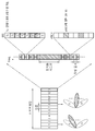
- FIG. 13 illustrates an association between an SSB, a core set # 0, and an SS set.
- the core set # 0 may be a core set for monitoring a DCI that delivers RMSI (Remaining system information) scheduling information.
- RMSI Remaining system information
- the position and size in the frequency domain and the duration in the time domain are transmitted through a PBCH (for example, PBCH). It may be set by a master information block (MIB), and the other coreset settings other than that may be fixed.
- MIB master information block
- the core set # 0 may be allocated a common search space (CSS) for other system information (OSI), paging, and random access. It may also be used for the purpose of transmitting a specific search space (USS) or UE-dedicated PDCCH (UE-dedicated PDCCH).
- SCS system information
- UE-dedicated PDCCH UE-dedicated PDCCH
- the TCI state may mean information required for the UE to configure the reception beam in the NR.
- the TCI state in coreset # 0 may be determined by the SSB to which the corresponding coreset / search space set is associated. Core set # 0 and search space set # 0 associated with each SSB may exist. Each terminal may perform measurement for each SSB and monitor coreset # 0 / search space set # 0 associated with the corresponding SSB based on the PBCH information of the SSB having the best measurement result.
- search space sets # 0, search space sets # 0-1, and the like are distinguished to distinguish search space sets # 0 by different SSBs.
- search space set # 0-X X means an associated SSB index.
- UE-dedicated PDSCH scheduling information may be transmitted in a region set for common search space (CSS) usage in coreset # 0.
- the terminal should perform monitoring for the corresponding DCI. For example, the following operations are possible.
- the network and the terminal maintain the same understanding for SSB / coreset # 0 / SS # 0 in connected mode (at least for non-broadcast PDCCH).
- SSB For the broadcast PDCCH, it may be a matter of the terminal implementation which SSB should be monitored based on the SSB in all of the connected mode, the inactive mode and the idle mode.
- the unicast PDSCH may be scheduled by the DCI associated with coreset # 0.
- the UE may be configured to set the search space set for each target by PBCH (ie, RMSI-PDCCH-Config), RMSI (ie, osi-searchSpace, paging-searchSpace, and ra-searchSpace).
- PBCH ie, RMSI-PDCCH-Config
- RMSI ie, osi-searchSpace, paging-searchSpace, and ra-searchSpace
- the DCI format 0_0 / 1_0 scrambled with C-RNTI / CS-RNTI can be monitored in addition to the target signal.
- monitoring of the broadcast PDCCH may be performed with respect to a search space set selected by the terminal (eg, search space set # 0-0 or search space set # 0-1 in FIG. 13).
- non-broadcast PDCCH monitoring should be performed in a selected search space set based on the same understanding of the network and the terminal. For example, the network expects the terminal to monitor in the search space set # 1, while the terminal performs the monitoring in the search space set # 2, which is a misunderstanding between the network and the terminal.
- the network may be inefficient because it may have to repeatedly transmit the PDCCH to all sets of search spaces associated with each SSB.
- both broadcast and non-broadcast may require the same understanding between networks and terminals in a specific mode.
- a valid TCI state may be set differently according to the search space index.
- the UE is signaled or the SSB index selected by the RACH process such as CBRA / CFRA (Contention Based RACH) / (Contention Free RACH) to select the search space # 0.
- CBRA / CFRA Contention Based RACH
- CFRA Contention Free RACH
- Monitoring opportunities / times can be determined. That is, in the case of the core set # 0 associated with the search space # 0, it may be preferable that the TCI state of the SSB unit or the CSI-RS / TRS associated with the SSB is set to the TCI state.
- the CSI-RS / TRS associated with the SSB may mean a CSI-RS / TRS in which a type D QCL relationship with the SSB is defined by a TCI state.
- the TCI state may be set regardless of the TCI type. Therefore, when the TCI state for coreset # 0 / search space # 0 is set or updated, if it is not the SSB index or CSI-RS / TRS associated with SSB, the TCI state is considered invalid.
- the existing TCI state can be maintained or a default TCI can be applied.
- whether the TCI type is valid may be determined based on the type of the corresponding search space (CSS / USS). For example, if the search space type is CSS, only the SSB index or CSI-RS / TRS associated with the SSB may be regarded as a valid TCI state, and if it is determined as an invalid TCI state, the existing TCI state is maintained or defaulted. The operation of updating to the TCI state may be taken.
- the above proposal may be applied to the valid TCI state among the candidate groups.
- the TCI state of the lowest index among the TCI state set (this is a superset of the TCI state set in the coreset) set for PDSCH and the like is used as the default TCI
- index # 0 is CSI-RS # 2
- index # 1 is set to SSB # 1
- the TCI state for coreset # 0 / search space # 0 can be set to index # 1 (SSB # 1), which is the lowest index among the valid TCI states
- index # 0 (CSI-RS # 2) can be set as the default TCI state.
- Criteria for validity of the TCI state may be considered as follows. (The options below can be implemented alone or in combination.
- a valid TCI state type for each coreset may be defined in advance or determined by an indication through higher layer signaling of the network. For example, it can be assumed that the coreset index # 0 is valid only for SSB type or CSI-RS / TRS associated with the SSB, and all other types of TCI states are valid through the predefined definition.
- the terminal receives an RRC signal including TCI-state settings (S141).
- the following table is an example of an RRC signal including TCI-state settings.
- 'tci-StatesToAddModList' is a list of TCI states, each TCI state indicating a transmission configuration including a QCL relationship between the downlink reference signal (s) and PDSCH DMRS port (s) in the reference signal set. can do.
- the UE may receive a MAC CE activation command through the PDSCH (S142).
- the MAC CE activation command may indicate one of the TCI states of the plurality of TCI states.
- the MAC CE activation command is identified by a field indicating a ID of a serving cell to which MAC CE is applied (Serving cell ID), a field indicating which coreset the TCI state is indicated by (CORESET ID), and a CORESET ID field. It may include a field (TCI State ID, for example, 7 bits) indicating a TCI state applicable to the core set.
- TCI State ID for example, 7 bits
- the UE may transmit ACK / NACK for the MAC CE activation command in slot n (S143).
- CORESET 15 illustrates a signal reception method in a core set (CORESET) according to an embodiment of the present invention.
- the terminal receives a radio resource control (RRC) signal including a plurality of TCI states (S100).
- RRC radio resource control
- the terminal receives a medium access control (MAC) Control Element (MAC) indicating one of the TCI states of the plurality of TCI states (S200).
- MAC medium access control
- the terminal receives a signal from the coreset based on the one TCI state (S300). For example, the terminal may receive a PDCCH (control information or control signal) in the coreset based on the one TCI state.
- the one TCI state may be related to a reference signal associated with a synchronization signal / physical broadcast channel block (SSB, SS / PBCH). That is, for the core set # 0, only the TCI state for setting / indicating the CSI-RS / TRS associated with the SSB can be regarded as valid.
- SSB synchronization signal / physical broadcast channel block
- the CSI-RS / TRS associated with the SSB may mean a CSI-RS / TRS in which a type D QCL relationship with the SSB is defined by a TCI state.
- the terminal may indicate that the QCL-TypeD of the CSI-RS in the TCI state indicated by the MAC CE activation command for the coreset # 0 is SS / PBCH. It can be expected to be provided based on the block (SSB).
- Quasi-co location (QCL) information of the reference signal may be determined based on the SSB.
- the reference signal may be a channel state information reference signal (CSI-RS).
- CSI-RS channel state information reference signal
- the one TCI state may include information about a quasi-co location (QCL) relationship between a demodulation reference signal (DMRS) port for the CSI-RS and a PDCCH / PDSCH.
- QCL quasi-co location
- the coreset # 0 may be configured by information (eg, MIB) transmitted through a physical broadcast channel (PBCH) or by dedicated RRC signaling.
- the MIB on the PBCH provides the UE with parameters (eg, coreset # 0 configuration) for monitoring the PDCCH scheduling the PDSCH carrying the system information block 1 (SIB 1).
- SIB1 may define a schedule of another system information block and include information required for initial access.
- SIB1 also called RMSI (Remaining Minimum SI)
- RMSI Remaining Minimum SI
- a demodulation reference signal (DM-RS) antenna port for receiving a PDCCH in the coreset # 0 may be simply referred to as a port.
- 1) is in quasi co-located with one or more downlink reference signals (e.g., TRS, CSI-RS) set by the TCI state indicated by the MAC CE activation command for the coreset.
- the SS / PBCH block (SSB) identified by the terminal during the most recent random access procedure, not initiated by the PDCCH command to trigger a non-contention based random access procedure. It can be assumed to be in a common location (if the MAC CE activation command indicating the TCI status for the coreset has not been received since the most recent random access procedure).
- the UE Upon receiving the MAC CE activation command for one of the TCI states, the UE transmits a DM-RS antenna port associated with the PDCCH reception in the coreset to one or more downlink reference signals configured by the one TCI state. It can be assumed to be in a common location.
- the UE has the QCL-TypeD of the CSI-RS in the TCI state indicated by the MAC CE activation command for the coreset # 0 being the SS / PBCH block ( It can be expected to be provided based on SSB).
- the TCI state indicated by the MAC CE activation command for coreset # 0 is limited to that associated with the reference signal associated with the synchronization signal / physical broadcast channel block (SSB, SS / PBCH), or the synchronization signal / It may be interpreted as valid only when indicating / setting a reference signal associated with a physical broadcast channel block (SSB, SS / PBCH).
- the MAC When the UE receives a MAC CE activation command for one of the TCI states, the MAC from the first slot after three subframes from the slot (eg, slot k) that transmitted the ACK / NACK for the MAC CE activation command.
- the CE activation command can be applied.
- the search space index can determine the validity of the TCI state. This may be determined by pre-definition or by indication through higher layer signaling of the network. For example, it can be assumed that search space index # 0 is valid only for SSB type or CSI-RS / TRS associated with SSB, and all other types of TCI states are valid through the dictionary definition.
- Whether the coreset and / or the search space beam sweeping may determine the validity of the TCI state. This may be determined by pre-definition or by indication through higher layer signaling of the network. For example, in the case of a coreset in which beam sweeping is performed, only SSB type or CSI-RS / TRS associated with SSB is valid, and in a coreset in which beam sweeping is not performed, it may be assumed that all types of TCI states are valid. have.
- the network may indicate a valid TCI state type and the like for each coreset and / or search space.
- the TCI state of the corresponding coreset may be set such that only the CSI-RS / TRS associated with the SSB type or the SSB is valid.
- a specific (index) TCI state of the TCI state set signaled for PDSCH or the like may be determined as the default TCI state.
- the specific TCI state may be determined by a predefined (eg, the lowest index TCI state) or by a network configuration such as higher layer signaling. This can be implemented without additional RRC signaling, and if there is a desire to change the default TCI state, the network has an advantage of changing the default TCI of the UE by using RRC resetting for the existing TCI state.
- a default TCI state is determined by using method 1 and / or 3, and when the TCI state set is signaled, a method such as updating the default value may be applied. .
- Coreset # 0 may have a plurality of connected search spaces.
- the TCI state of coreset # 0 may be updated based on the MAC CE in the set of established TCI states.
- the monitoring opportunity for the search of the TCI information and the search space # 0 may follow the following options.
- the monitoring opportunity of search space # 0 can always be based on the SSB index used in the most recent RACH process. If CFRA is triggered in the most recent RACH procedure, the SSB associated with the CSI-RS is assumed for the SSB index. If the CSI-RS is not associated with the SSB, the previous monitoring opportunity / association is used. That is, the SSB index selected previously may be used or may be regarded as an error.
- the TCI state of the coreset # 0 including the search space # 0 may be updated according to the MAC CE if the MAC CE indicates the TCI state. Otherwise, the QCL of the SSB index used in the most recent RACH procedure may be followed.
- the monitoring opportunity of search space # 0 may be based on the TCI state updated by the SSB index or MAC CE in the most recent RACH.
- the associated SSB index can be used. If there is no SSB associated, the most recent RACH procedure may be used or this situation may be considered an error.
- the TCI state can only be updated by the MAC CE.
- the monitoring opportunity of search space # 0 may be based on the latest RACH process or the TCI state updated by the MAC CE.
- the associated SSB index is used. If there is no SSB associated, the most recent RACH procedure may be used or this situation may be considered to be an error.
- the TCI state may be updated based on the MAC CE or the most recent RACH procedure. For the SSB based RACH procedure, the TCI state is assumed based on the SSB.
- determining the monitoring opportunity of SS # 0 when TCI is set to coreset # 0 follows only SSB-based RACH procedure (including CSI-RS related to SSB-based RACH procedure) or the most recent RACH procedure or MAC CE. You can follow the most recent SSB index derived from the update.
- i) can always follow only MAC CE (when MAC CE is available or available), or ii) follow the most recent event of RACH and MAC CE (QCL relationship for RACH, but QCL information may be updated based on the RACH procedure for which no TCI status is defined).
- 16 is a block diagram illustrating the components of a transmitting device 1810 and a receiving device 1820 implementing the present invention.
- the transmitting device and the receiving device may each be a base station (network) or a terminal.
- the transmitting device 1810 and the receiving device 1820 are transceivers 1812 and 1822 capable of transmitting or receiving wireless signals carrying information and / or data, signals, messages, and the like, and various kinds of information related to communication in a wireless communication system. Is connected to components such as the memory 1813 and 1823, the transceivers 1812 and 1822, and the memory 1813 and 1823 to control the components to control the components. Processors 1811 and 1821 configured to control the memory 1813 and 1823 and / or the transceivers 1812 and 1822 to perform at least one, respectively.
- the transceiver may be called a transceiver.
- the memory 1813 and 1823 may store a program for processing and controlling the processors 1811 and 1821, and may temporarily store input / output information.
- the memories 1813 and 1823 may be utilized as buffers.
- Processors 1811 and 1821 typically control the overall operation of various modules in a transmitting device or a receiving device.
- the processors 1811 and 1821 may perform various control functions for performing the present invention.
- the processors 1811 and 1821 may also be referred to as controllers, microcontrollers, microprocessors, microcomputers, or the like.
- the processors 1811 and 1821 may be implemented by hardware or firmware, software, or a combination thereof.
- ASICs application specific integrated circuits
- DSPs digital signal processors
- DSPDs digital signal processing devices
- PLDs programmable logic devices
- FPGAs field programmable gate arrays
- the firmware or software may be configured to include a module, a procedure, or a function that performs the functions or operations of the present invention, and is configured to perform the present invention.
- the firmware or software may be provided in the processors 1811 and 1821 or stored in the memories 1813 and 1823 to be driven by the processors 1811 and 1821.
- the processor 1811 of the transmission device 1810 may perform a predetermined encoding and modulation on a signal and / or data to be transmitted to the outside and then transmit the same to the transceiver 1812.
- the processor 1811 may generate a codeword through demultiplexing, channel encoding, scrambling, modulation, and the like, of a data string to be transmitted.
- the codeword may include information equivalent to a transport block which is a data block provided by the MAC layer.
- One transport block (TB) may be encoded with one codeword.
- Each codeword may be transmitted to the receiving device through one or more layers.
- the transceiver 1812 may include an oscillator for frequency up-convert.
- the transceiver 1812 may include one or a plurality of transmit antennas.
- the signal processing of the reception device 1820 may be configured as the inverse of the signal processing of the transmission device 1810.
- the transceiver 1822 of the receiving device 1820 may receive a radio signal transmitted by the transmitting device 1810.
- the transceiver 1822 may include one or a plurality of receive antennas.
- the transceiver 1822 may restore the baseband signal by frequency down-converting each of the signals received through the receiving antenna.
- the transceiver 1822 may include an oscillator for frequency downconversion.
- the processor 1821 may restore data originally intended to be transmitted by the transmission device 1810 by performing decoding and demodulation on the radio signal received through the reception antenna.
- the transceivers 1812 and 1822 may be equipped with one or a plurality of antennas.
- the antenna transmits a signal processed by the transceivers 1812 and 1822 to the outside under the control of the processors 1811 and 1821, or receives a radio signal from the outside to receive the transceivers 1812 and 1822. ) Can be delivered.
- the antenna may be referred to as an antenna port.
- Each antenna may correspond to one physical antenna or may be configured by a combination of more than one physical antenna elements.
- the signal transmitted from each antenna can no longer be resolved by the receiving device 1820.
- a reference signal (RS) transmitted corresponding to the corresponding antenna defines an antenna viewed from the perspective of the receiving device 1820, and includes a channel or whether the channel is a single radio channel from one physical antenna.
- RS reference signal
- the receiving device 1820 may enable channel estimation for the antenna. That is, the antenna may be defined such that a channel carrying a symbol on the antenna can be derived from the channel through which another symbol on the same antenna is delivered.
- a transceiver supporting a multi-input multi-output (MIMO) function for transmitting and receiving data using a plurality of antennas may be connected to two or more antennas.
- MIMO multi-input multi-output
- FIG. 17 illustrates an example of a signal processing module structure in the transmission device 1810.
- the signal processing may be performed in a processor of the base station / terminal, such as the processors 1811 and 1821 of FIG. 16.
- a transmission device 1810 in a terminal or a base station includes a scrambler 301, a modulator 302, a layer mapper 303, an antenna port mapper 304, a resource block mapper 305, and a signal generator 306. ) May be included.
- the transmitting device 1810 may transmit one or more codewords.
- the coded bits in each codeword are scrambled by the scrambler 301 and transmitted on the physical channel.
- the codeword may be referred to as a data string and may be equivalent to a transport block which is a data block provided by the MAC layer.
- the scrambled bits are modulated into complex-valued modulation symbols by the modulator 302.
- the modulator 302 may modulate the scrambled bits according to a modulation scheme and place them as complex modulation symbols representing positions on a signal constellation.
- m-PSK m-Phase Shift Keying
- m-QAM m-Quadrature Amplitude Modulation
- the modulator may be referred to as a modulation mapper.
- the complex modulation symbol may be mapped to one or more transport layers by a layer mapper 303.
- Complex modulation symbols on each layer may be mapped by antenna port mapper 304 for transmission on the antenna port.
- the resource block mapper 305 may map the complex modulation symbol for each antenna port to the appropriate resource element in the virtual resource block allocated for transmission.
- the resource block mapper may map the virtual resource block to a physical resource block according to an appropriate mapping scheme.
- the resource block mapper 305 may assign a complex modulation symbol for each antenna port to an appropriate subcarrier and multiplex according to a user.
- the signal generator 306 modulates a complex modulation symbol for each antenna port, that is, an antenna specific symbol by a specific modulation scheme, for example, an orthogonal frequency division multiplexing (OFDM) scheme, thereby complex-valued time domain.
- An OFDM symbol signal can be generated.
- the signal generator may perform an inverse fast fourier transform (IFFT) on an antenna specific symbol, and a cyclic prefix (CP) may be inserted into a time domain symbol on which the IFFT is performed.
- IFFT inverse fast fourier transform
- CP cyclic prefix
- the OFDM symbol is transmitted to the receiving apparatus through each transmit antenna through digital-to-analog conversion, frequency upconversion, and the like.
- the signal generator may include an IFFT module and a CP inserter, a digital-to-analog converter (DAC), a frequency uplink converter, and the like.
- the signal processing may be performed in a processor of the terminal / base station such as the processors 1811 and 1821 of FIG. 16.
- a transmission device 1810 in a terminal or a base station includes a scrambler 401, a modulator 402, a layer mapper 403, a precoder 404, a resource block mapper 405, and a signal generator 406. It may include.
- the transmitting device 1810 may scramble the coded bits in the codeword by the scrambler 401 and transmit the coded bits in one codeword through a physical channel.
- the scrambled bits are modulated into complex modulation symbols by modulator 402.
- the modulator may be arranged as a complex modulation symbol representing a position on a signal constellation by modulating the scrambled bit according to a predetermined modulation scheme.
- the modulation scheme is not limited, and pi / 2-Binary Phase Shift Keying (pi / 2-BPSK), m-Phase Shift Keying (m-PSK), or m-Quadrature Amplitude Modulation (m-QAM) It can be used for modulation of the encoded data.
- the complex modulation symbol may be mapped to one or more transport layers by the layer mapper 403.
- Complex modulation symbols on each layer may be precoded by the precoder 404 for transmission on the antenna port.
- the precoder may perform precoding after performing transform precoding on the complex modulation symbol.
- the precoder may perform precoding without performing transform precoding.
- the precoder 404 may process the complex modulation symbol in a MIMO scheme according to a multiplexing antenna to output antenna specific symbols and distribute the antenna specific symbols to the corresponding resource block mapper 405.
- the output z of the precoder 404 can be obtained by multiplying the output y of the layer mapper 403 by a precoding matrix W of N ⁇ M. Where N is the number of antenna ports and M is the number of layers.
- the resource block mapper 405 maps the demodulation modulation symbol for each antenna port to the appropriate resource element in the virtual resource block allocated for transmission.
- the RB mapper 405 may assign a complex modulation symbol to an appropriate subcarrier and multiplex it according to a user.
- the signal generator 406 may generate a complex-valued time domain (OFDM) orthogonal frequency division multiplexing (OFDM) symbol signal by modulating the complex modulation symbol in a specific modulation scheme, for example, the OFDM scheme.
- the signal generator 406 may perform an inverse fast fourier transform (IFFT) on an antenna specific symbol, and a cyclic prefix (CP) may be inserted into a time domain symbol on which the IFFT is performed.
- IFFT inverse fast fourier transform
- CP cyclic prefix
- the OFDM symbol is transmitted to the receiving apparatus through each transmit antenna through digital-to-analog conversion, frequency upconversion, and the like.
- the signal generator 406 may include an IFFT module and a CP inserter, a digital-to-analog converter (DAC), a frequency uplink converter, and the like.
- the signal processing of the receiver 1820 may be configured as the inverse of the signal processing of the transmitter.
- the processor 1821 of the receiver 1820 performs decoding and demodulation on the radio signal received through the antenna port (s) of the transceiver 1822 from the outside.
- the receiving device 1820 may include a plurality of multiple receiving antennas, and each signal received through the receiving antenna is restored to a baseband signal, and then transmitted by the transmitting device 1810 through multiplexing and MIMO demodulation. The data sequence is restored.
- the receiver 1820 may include a signal recoverer for recovering the received signal into a baseband signal, a multiplexer for combining and multiplexing the received processed signal, and a channel demodulator for demodulating the multiplexed signal sequence with a corresponding codeword.
- the signal reconstructor, multiplexer, and channel demodulator may be composed of one integrated module or each independent module for performing their functions. More specifically, the signal reconstructor is an analog-to-digital converter (ADC) for converting an analog signal into a digital signal, a CP remover for removing a CP from the digital signal, and a fast fourier transform (FFT) to the signal from which the CP is removed.
- ADC analog-to-digital converter
- FFT fast fourier transform
- FFT module for outputting a frequency domain symbol by applying a, and may include a resource element demapper (equalizer) to restore the frequency domain symbol to an antenna-specific symbol (equalizer).
- the antenna specific symbol is restored to a transmission layer by a multiplexer, and the transmission layer is restored to a codeword that the transmitting device intends to transmit by a channel demodulator.
- FIG. 19 illustrates an example of a wireless communication device according to an embodiment of the present invention.
- a wireless communication device for example, a terminal may include a processor 2310 such as a digital signal processor (DSP) or a microprocessor, a transceiver 2335, a power management module 2305, an antenna ( 2340, battery 2355, display 2315, keypad 2320, GPS (Global Positioning System) chip 2360, sensor 2365, memory 2330, SIM (Subscriber Identification Module) card 2325, At least one of the speaker 2345 and the microphone 2350 may be included. There may be a plurality of antennas and processors.
- DSP digital signal processor
- the processor 2310 may implement the functions, procedures, and methods described herein.
- the processor 2310 of FIG. 19 may be the processors 1811 and 1821 of FIG. 16.
- the memory 2330 is connected to the processor 2310 and stores information related to the operation of the processor.
- the memory may be located inside or outside the processor and may be connected to the processor through various technologies such as a wired connection or a wireless connection.
- the memory 2330 of FIG. 19 may be the memories 1813 and 1823 of FIG. 16.
- the user may input various kinds of information such as a telephone number using various techniques such as pressing a button of the keypad 2320 or activating a sound using the microphone 2350.
- the processor 2310 may perform appropriate functions, such as receiving and processing user information, calling an input telephone number, and the like.
- data may be retrieved from SIM card 2325 or memory 2330 to perform the appropriate function.
- the processor 2310 may display various kinds of information and data on the display 2315 for the convenience of the user.
- the transceiver 2335 is connected to the processor 2310 to transmit and / or receive a radio signal such as a radio frequency (RF) signal.
- the processor may control the transceiver to initiate communication or to transmit a wireless signal including various kinds of information or data such as voice communication data.
- the transceiver includes a transmitter and a receiver for transmitting and receiving wireless signals.
- Antenna 2340 may facilitate the transmission and reception of wireless signals.
- the transceiver can forward and convert the signal to baseband frequency for processing by the processor upon receiving the wireless signal.
- the processed signal may be processed by various techniques, such as being converted into audible or readable information to be output through the speaker 2345.
- the transceiver of FIG. 19 may be the transceivers 1812 and 1822 of FIG. 16.
- various components such as a camera and a universal serial bus (USB) port may be additionally included in the terminal.
- the camera may be connected to the processor 2310.
- the terminal 19 is only one implementation of the terminal, and the implementation is not limited thereto.
- the terminal does not necessarily need to include all the elements of FIG. 19. That is, some components, for example, the keypad 2320, the GPS (Global Positioning System) chip 2360, the sensor 2365, the SIM card 2325 may not be an essential element, and in this case, the terminal is not included in the terminal. It may not.
- the keypad 2320, the GPS (Global Positioning System) chip 2360, the sensor 2365, the SIM card 2325 may not be an essential element, and in this case, the terminal is not included in the terminal. It may not.
- FIG 20 illustrates an example of the processor 2000.
- the processor 2000 may include an RRC signal and / or a MAC CE reception processing module 2010 and a PDCCH reception processing module 2020.
- the processor 2000 may execute the methods (entry of the receiver) described with reference to FIGS. 14 to 15.
- the processor 2000 receives an RRC signal including a plurality of TCI states, receives a MAC CE indicating a TCI state of any of the plurality of TCI states, and based on the one TCI state.
- the processor 2000 may be an example of the processors 1811 and 1821 of FIG. 16.
- 21 illustrates an example of the processor 3000.
- the processor 3000 may include a TCI allocation module 3010 and an information transmission module 3020.
- the processor 3000 may execute the methods described in terms of the transmitter in FIGS. 14 to 15. For example, the processor 3000 may determine and assign TCI states for each coreset.
- the RCI signal or the combination of the RRC signal and the MAC CE may be used to indicate (notify) the TCI state for the coreset and thus transmit the PDCCH (specifically, transmit control information) in the coreset.
- the processor 3000 may be an example of the processors 1811 and 1821 of FIG. 16.
- FIG. 22 shows an example of a 5G usage scenario to which the technical features of the present invention can be applied.
- the 5G usage scenario shown in FIG. 22 is merely exemplary, and the technical features of the present invention may be applied to other 5G usage scenarios not shown in FIG. 22.
- enhanced mobile broadband (eMBB) area (2) massive machine type communication (mMTC) area, and ( 3) ultra-reliable and low latency communications (URLLC).
- eMBB enhanced mobile broadband
- mMTC massive machine type communication
- URLLC ultra-reliable and low latency communications
- KPI key performance indicator
- eMBB focuses on improving data rate, latency, user density, overall capacity and coverage of mobile broadband access.
- eMBB aims at throughput of around 10Gbps.
- eMBB goes far beyond basic mobile Internet access and covers media and entertainment applications in rich interactive work, cloud or augmented reality.
- Data is one of the key drivers of 5G and may not see dedicated voice services for the first time in the 5G era.
- voice is expected to be treated as an application simply using the data connection provided by the communication system.
- the main reason for the increased traffic volume is the increase in content size and the increase in the number of applications requiring high data rates.
- Streaming services (audio and video), interactive video, and mobile Internet connections will become more popular as more devices connect to the Internet.
- Cloud storage and applications are growing rapidly in mobile communication platforms, which can be applied to both work and entertainment.
- Cloud storage is a special use case that drives the growth of uplink data rates.
- 5G is also used for remote tasks in the cloud and requires much lower end-to-end delays to maintain a good user experience when tactile interfaces are used.
- cloud gaming and video streaming are another key factor in increasing the need for mobile broadband capabilities.
- Entertainment is essential in smartphones and tablets anywhere, including in high mobility environments such as trains, cars and airplanes.
- Another use case is augmented reality and information retrieval for entertainment.
- augmented reality requires very low latency and instantaneous amount of data.
- the mMTC is designed to enable communication between a large number of low-cost devices powered by batteries and to support applications such as smart metering, logistics, field and body sensors.
- mMTC targets 10 years of battery and / or about 1 million devices per square kilometer.
- the mMTC enables seamless connection of embedded sensors in all applications and is one of the most anticipated 5G use cases. Potentially, 2020 IoT devices are expected to reach 20 billion.
- Industrial IoT is one of the areas where 5G plays a major role in enabling smart cities, asset tracking, smart utilities, agriculture and security infrastructure.
- URLLC enables devices and machines to communicate very reliably and with very low latency and high availability, making them ideal for vehicle communications, industrial control, factory automation, telesurgery, smart grid and public safety applications.
- URLLC aims for a delay of around 1ms.
- URLLC includes new services that will transform the industry through ultra-reliable / low-latency links such as remote control of key infrastructure and autonomous vehicles. The level of reliability and latency is essential for smart grid control, industrial automation, robotics, drone control and coordination.
- 5G can complement fiber-to-the-home (FTTH) and cable-based broadband (or DOCSIS) as a means of providing streams that are rated at hundreds of megabits per second to gigabits per second. This high speed may be required to deliver TVs at resolutions of 4K or higher (6K, 8K and higher) as well as virtual reality (VR) and augmented reality (AR).
- VR and AR applications include nearly immersive sports events. Certain applications may require special network settings. For example, in a VR game, the game company may need to integrate the core server with the network operator's edge network server to minimize latency.
- Automotive is expected to be an important new driver for 5G, with many uses for mobile communications to vehicles. For example, entertainment for passengers demands both high capacity and high mobile broadband at the same time. This is because future users continue to expect high quality connections regardless of their location and speed.
- Another use of the automotive sector is augmented reality dashboards.
- the augmented reality contrast board allows the driver to identify objects in the dark above what they are looking through through the front window.
- the augmented reality dashboard superimposes information that tells the driver about the distance and movement of the object.
- wireless modules enable communication between vehicles, the exchange of information between the vehicle and the supporting infrastructure, and the exchange of information between the vehicle and other connected devices (eg, devices carried by pedestrians).
- the safety system guides alternative courses of action to help drivers drive safer, reducing the risk of an accident.
- the next step will be a remote controlled vehicle or an autonomous vehicle.
- This requires very reliable and very fast communication between different autonomous vehicles and / or between cars and infrastructure.
- autonomous vehicles will perform all driving activities and allow drivers to focus on traffic anomalies that the vehicle itself cannot identify.
- the technical requirements of autonomous vehicles require ultra-low latency and ultrafast reliability to increase traffic safety to an unachievable level.
- Smart cities and smart homes will be embedded into high-density wireless sensor networks.
- the distributed network of intelligent sensors will identify the conditions for cost and energy efficient maintenance of the city or home. Similar settings can be made for each hypothesis.
- Temperature sensors, window and heating controllers, burglar alarms and appliances are all connected wirelessly. Many of these sensors typically require low data rates, low power and low cost. However, for example, real time HD video may be required in certain types of devices for surveillance.
- Smart grids interconnect these sensors using digital information and communication technologies to gather information and act accordingly. This information can include the behavior of suppliers and consumers, allowing smart grids to improve the distribution of fuels such as electricity in efficiency, reliability, economics, sustainability of production, and in an automated manner. Smart Grid can be viewed as another sensor network with low latency.
- the health sector has many applications that can benefit from mobile communications.
- the communication system can support telemedicine, providing clinical care at a distance. This can help reduce barriers to distance and improve access to health services that are not consistently available in remote rural areas. It is also used to save lives in critical care and emergencies.
- Mobile communication based wireless sensor networks may provide remote monitoring and sensors for parameters such as heart rate and blood pressure.
- Wireless and mobile communications are becoming increasingly important in industrial applications. Wiring is expensive to install and maintain. Thus, the possibility of replacing the cable with a reconfigurable wireless link is an attractive opportunity in many industries. However, achieving this requires that the wireless connection operate with cable-like delay, reliability, and capacity, and that management is simplified. Low latency and very low error probability are new requirements that need to be connected in 5G.
- Logistics and freight tracking is an important use case for mobile communications that enables the tracking of inventory and packages from anywhere using a location-based information system.
- the use of logistics and freight tracking typically requires low data rates but requires wide range and reliable location information.
- FIG. 23 illustrates a wireless communication device according to an embodiment of the present invention.
- a wireless communication system may include a first device 9010 and a second device 9020.
- the first device 9010 includes a base station, a network node, a transmitting terminal, a receiving terminal, a wireless device, a wireless communication device, a vehicle, a vehicle equipped with an autonomous driving function, a connected car, a drone (Unmanned Aerial Vehicle, UAV, artificial intelligence module, robot, augmented reality device, virtual reality device, mixed reality device, hologram device, public safety device, MTC device, IoT device, medical device, pin It may be a tech device (or financial device), a security device, a climate / environment device, a device related to 5G service, or another device related to the fourth industrial revolution field.
- UAV Unmanned Aerial Vehicle
- UAV artificial intelligence module
- robot augmented reality device
- virtual reality device virtual reality device
- mixed reality device mixed reality device
- hologram device public safety device
- MTC device IoT device
- medical device pin It may be a tech device (or financial device), a security device, a climate / environment device, a device related to 5G service
- the second device 9020 includes a base station, a network node, a transmitting terminal, a receiving terminal, a wireless device, a wireless communication device, a vehicle, a vehicle equipped with an autonomous driving function, a connected car, a drone (Unmanned Aerial Vehicle, UAV, artificial intelligence module, robot, augmented reality device, virtual reality device, mixed reality device, hologram device, public safety device, MTC device, IoT device, medical device, pin It may be a tech device (or financial device), a security device, a climate / environment device, a device related to 5G service, or another device related to the fourth industrial revolution field.
- UAV Unmanned Aerial Vehicle
- UAV artificial intelligence module
- robot augmented reality device
- virtual reality device virtual reality device
- mixed reality device mixed reality device
- hologram device public safety device
- MTC device IoT device
- medical device pin It may be a tech device (or financial device), a security device, a climate / environment device, a device related to 5G service
- the terminal may be a mobile phone, a smart phone, a laptop computer, a digital broadcasting terminal, a personal digital assistant (PDA), a portable multimedia player (PMP), navigation, a slate PC, a tablet. It may include a tablet PC, an ultrabook, a wearable device (eg, a smartwatch, a glass glass, a head mounted display), and the like.
- the HMD may be a display device worn on the head.
- the HMD can be used to implement VR, AR or MR.
- a drone may be a vehicle in which humans fly by radio control signals.
- the VR device may include a device that implements an object or a background of a virtual world.
- the AR device may include a device that connects and implements an object or a background of the virtual world to an object or a background of the real world.
- the MR device may include a device that fuses and implements an object or a background of the virtual world to an object or a background of the real world.
- the hologram device may include a device that records and reproduces stereoscopic information to realize a 360 degree stereoscopic image by utilizing interference of light generated by two laser lights, called holography, to meet each other.
- the public safety device may include an image relay device or an image device wearable on a human body of a user.
- the MTC device and the IoT device may be devices that do not require direct human intervention or manipulation.
- the MTC device and the IoT device may include a smart meter, a bending machine, a thermometer, a smart bulb, a door lock or various sensors.
- the medical device may be a device used for the purpose of diagnosing, treating, alleviating, treating or preventing a disease.
- a medical device may be a device used for the purpose of diagnosing, treating, alleviating or correcting an injury or disorder.
- a medical device may be a device used for the purpose of inspecting, replacing, or modifying a structure or function.
- the medical device may be a device used for controlling pregnancy.
- the medical device may include a medical device, a surgical device, an (in vitro) diagnostic device, a hearing aid or a surgical device, and the like.
- the security device may be a device installed to prevent a risk that may occur and to maintain safety.
- the security device may be a camera, a CCTV, a recorder or a black box.
- the fintech device may be a device capable of providing financial services such as mobile payment.
- the fintech device may include a payment device or a point of sales (POS).
- the climate / environmental device may include a device for monitoring or predicting the climate / environment.
- the first device 9010 may include at least one or more processors, such as a processor 9011, at least one or more memories, such as a memory 9012, and at least one or more transceivers, such as a transceiver 9013.
- the processor 9011 may perform the functions, procedures, and / or methods described above.
- the processor 9011 may perform one or more protocols.
- the processor 9011 may perform one or more layers of a radio interface protocol.
- the memory 9012 is connected to the processor 9011 and may store various types of information and / or instructions.
- the transceiver 9013 may be connected to the processor 9011 and controlled to transmit and receive a wireless signal.
- the second device 9020 may include at least one processor such as the processor 9021, at least one memory device such as the memory 9022, and at least one transceiver such as the transceiver 9023.
- the processor 9021 may perform the functions, procedures, and / or methods described above.
- the processor 9021 may implement one or more protocols.
- the processor 9021 may implement one or more layers of a radio interface protocol.
- the memory 9022 is connected to the processor 9021 and may store various types of information and / or instructions.
- the transceiver 9023 is connected to the processor 9021 and may be controlled to transmit and receive a wireless signal.
- the memory 9012 and / or the memory 9022 may be respectively connected inside or outside the processor 9011 and / or the processor 9021, and may be connected to other processors through various technologies such as a wired or wireless connection. It may also be connected to.
- the first device 9010 and / or the second device 9020 may have one or more antennas.
- antenna 9014 and / or antenna 9024 may be configured to transmit and receive wireless signals.
- the present invention may be applied to the following fields.
- Machine learning refers to the field of researching methodologies to define and solve various problems dealt with in the field of artificial intelligence. do.
- Machine learning is defined as an algorithm that improves the performance of a task through a consistent experience with a task.
- ANN Artificial Neural Network
- the artificial neural network may be defined by a connection pattern between neurons of different layers, a learning process of updating model parameters, and an activation function generating an output value.
- the artificial neural network may include an input layer, an output layer, and optionally one or more hidden layers. Each layer contains one or more neurons, and the artificial neural network may include synapses that connect neurons to neurons. In an artificial neural network, each neuron may output a function value of an active function for input signals, weights, and deflections input through a synapse.
- the model parameter refers to a parameter determined through learning and includes weights of synaptic connections and deflection of neurons.
- the hyperparameter means a parameter to be set before learning in the machine learning algorithm, and includes a learning rate, the number of iterations, a mini batch size, an initialization function, and the like.
- the purpose of learning artificial neural networks can be seen as determining model parameters that minimize the loss function.
- the loss function can be used as an index for determining an optimal model parameter in the learning process of an artificial neural network.
- Machine learning can be categorized into supervised learning, unsupervised learning, and reinforcement learning.
- Supervised learning refers to a method of learning artificial neural networks with a given label for training data, and a label indicates a correct answer (or result value) that the artificial neural network must infer when the training data is input to the artificial neural network.
- Unsupervised learning may refer to a method of training artificial neural networks in a state where a label for training data is not given.
- Reinforcement learning can mean a learning method that allows an agent defined in an environment to learn to choose an action or sequence of actions that maximizes cumulative reward in each state.
- Machine learning which is implemented as a deep neural network (DNN) including a plurality of hidden layers among artificial neural networks, is called deep learning (Deep Learning), which is part of machine learning.
- DNN deep neural network
- Deep Learning Deep Learning
- machine learning is used to mean deep learning.
- a robot can mean a machine that automatically handles or operates a given task by its own ability.
- a robot having a function of recognizing the environment, judging itself, and performing an operation may be referred to as an intelligent robot.
- Robots can be classified into industrial, medical, household, military, etc. according to the purpose or field of use.
- the robot may include a driving unit including an actuator or a motor to perform various physical operations such as moving a robot joint.
- the movable robot includes a wheel, a brake, a propeller, and the like in the driving unit, and can travel on the ground or fly in the air through the driving unit.
- Autonomous driving means a technology that drives by itself, and an autonomous vehicle means a vehicle that runs without a user's manipulation or with minimal manipulation of a user.
- the technology of maintaining a driving lane the technology of automatically adjusting speed such as adaptive cruise control, the technology of automatically driving along a predetermined route, the technology of automatically setting a route when a destination is set, etc. All of these may be included.
- the vehicle includes a vehicle having only an internal combustion engine, a hybrid vehicle having both an internal combustion engine and an electric motor together, and an electric vehicle having only an electric motor, and may include not only automobiles but also trains and motorcycles.
- the autonomous vehicle may be viewed as a robot having an autonomous driving function.
- Extended reality collectively refers to virtual reality (VR), augmented reality (AR), and mixed reality (MR).
- VR technology provides real world objects and backgrounds only in CG images
- AR technology provides virtual CG images on real objects images
- MR technology mixes and combines virtual objects in the real world.
- Graphic technology
- MR technology is similar to AR technology in that it shows both real and virtual objects.
- virtual objects are used as complementary objects to real objects, whereas in MR technology, virtual objects and real objects are used in an equivalent nature.
- HMD Head-Mount Display
- HUD Head-Up Display
- mobile phone tablet PC, laptop, desktop, TV, digital signage, etc. It can be called.
- FIG 24 illustrates an AI device 100 according to an embodiment of the present invention.
- the AI device 100 includes a TV, a projector, a mobile phone, a smartphone, a desktop computer, a notebook computer, a digital broadcasting terminal, a personal digital assistant (PDA), a portable multimedia player (PMP), a navigation device, a tablet PC, a wearable device, and a set-top box (STB). ), A DMB receiver, a radio, a washing machine, a refrigerator, a desktop computer, a digital signage, a robot, a vehicle, or the like.
- PDA personal digital assistant
- PMP portable multimedia player
- STB set-top box
- the terminal 100 connects the communication unit 110, the input unit 120, the running processor 130, the sensing unit 140, the output unit 150, the memory 170, the processor 180, and the like. It may include.
- the communicator 110 may transmit / receive data to / from external devices such as the other AI devices 100a to 100e or the AI server 200 using wired or wireless communication technology.
- the communicator 110 may transmit / receive sensor information, a user input, a learning model, a control signal, and the like with external devices.
- the communication technology used by the communication unit 110 may include Global System for Mobile Communication (GSM), Code Division Multi Access (CDMA), Long Term Evolution (LTE), 5G, Wireless LAN (WLAN), and Wireless-Fidelity (Wi-Fi). ), Bluetooth TM, Radio Frequency Identification (RFID), Infrared Data Association (IrDA), ZigBee, and Near Field Communication (NFC).
- GSM Global System for Mobile Communication
- CDMA Code Division Multi Access
- LTE Long Term Evolution
- 5G Fifth Generation
- Wi-Fi Wireless LAN
- Wi-Fi Wireless-Fidelity
- Bluetooth TM Radio Frequency Identification
- RFID Radio Frequency Identification
- IrDA Infrared Data Association
- ZigBee ZigBee
- NFC Near Field Communication
- the input unit 120 may acquire various types of data.
- the input unit 120 may include a camera for inputting an image signal, a microphone for receiving an audio signal, a user input unit for receiving information from a user, and the like.
- a signal obtained from the camera or microphone may be referred to as sensing data or sensor information by treating the camera or microphone as a sensor.
- the input unit 120 may acquire input data to be used when acquiring an output using training data and a training model for model training.
- the input unit 120 may obtain raw input data, and in this case, the processor 180 or the running processor 130 may extract input feature points as preprocessing on the input data.
- the running processor 130 may train a model composed of artificial neural networks using the training data.
- the learned artificial neural network may be referred to as a learning model.
- the learning model may be used to infer result values for new input data other than the training data, and the inferred values may be used as a basis for judgment to perform an operation.
- the running processor 130 may perform AI processing together with the running processor 240 of the AI server 200.
- the running processor 130 may include a memory integrated with or implemented in the AI device 100.
- the running processor 130 may be implemented using the memory 170, an external memory directly coupled to the AI device 100, or a memory held in the external device.
- the sensing unit 140 may acquire at least one of internal information of the AI device 100, surrounding environment information of the AI device 100, and user information using various sensors.
- the sensors included in the sensing unit 140 include a proximity sensor, an illumination sensor, an acceleration sensor, a magnetic sensor, a gyro sensor, an inertial sensor, an RGB sensor, an IR sensor, a fingerprint sensor, an ultrasonic sensor, an optical sensor, a microphone, and a li. , Radar and so on.
- the output unit 150 may generate an output related to visual, auditory, or tactile.
- the output unit 150 may include a display unit for outputting visual information, a speaker for outputting auditory information, and a haptic module for outputting tactile information.
- the memory 170 may store data supporting various functions of the AI device 100.
- the memory 170 may store input data, training data, training model, training history, and the like acquired by the input unit 120.
- the processor 180 may determine at least one executable operation of the AI device 100 based on the information determined or generated using the data analysis algorithm or the machine learning algorithm. In addition, the processor 180 may control the components of the AI device 100 to perform a determined operation.
- the processor 180 may request, search, receive, or utilize data of the running processor 130 or the memory 170, and may perform an operation predicted or determined to be preferable among the at least one executable operation.
- the components of the AI device 100 may be controlled to execute.
- the processor 180 may generate a control signal for controlling the corresponding external device and transmit the generated control signal to the corresponding external device.
- the processor 180 may obtain intention information about the user input, and determine the user's requirements based on the obtained intention information.
- the processor 180 uses at least one of a speech to text (STT) engine for converting a voice input into a string or a natural language processing (NLP) engine for obtaining intention information of a natural language. Intent information corresponding to the input can be obtained.
- STT speech to text
- NLP natural language processing
- At least one or more of the STT engine or the NLP engine may be configured as an artificial neural network, at least partly learned according to a machine learning algorithm. At least one of the STT engine or the NLP engine may be learned by the running processor 130, may be learned by the running processor 240 of the AI server 200, or may be learned by distributed processing thereof. It may be.
- the processor 180 collects history information including operation contents of the AI device 100 or feedback of a user about the operation, and stores the information in the memory 170 or the running processor 130, or the AI server 200. Can transmit to external device. The collected historical information can be used to update the learning model.
- the processor 180 may control at least some of the components of the AI device 100 to drive an application program stored in the memory 170. In addition, the processor 180 may operate by combining two or more of the components included in the AI device 100 to drive the application program.
- FIG 25 illustrates an AI server 200 according to an embodiment of the present invention.
- the AI server 200 may refer to an apparatus for learning an artificial neural network using a machine learning algorithm or using an learned artificial neural network.
- the AI server 200 may be composed of a plurality of servers to perform distributed processing, or may be defined as a 5G network.
- the AI server 200 may be included as a part of the AI device 100 to perform at least some of the AI processing together.
- the AI server 200 may include a communication unit 210, a memory 230, a running processor 240, a processor 260, and the like.
- the communication unit 210 may transmit / receive data with an external device such as the AI device 100.
- the memory 230 may include a model storage unit 231.
- the model storage unit 231 may store a trained model or a trained model (or artificial neural network 231a) through the running processor 240.
- the running processor 240 may train the artificial neural network 231a using the training data.
- the learning model may be used while mounted in the AI server 200 of the artificial neural network, or may be mounted and used in an external device such as the AI device 100.
- the learning model can be implemented in hardware, software or a combination of hardware and software. When some or all of the learning model is implemented in software, one or more instructions constituting the learning model may be stored in the memory 230.
- the processor 260 may infer a result value with respect to the new input data using the learning model, and generate a response or control command based on the inferred result value.
- 26 shows an AI system 1 according to an embodiment of the present invention.
- the AI system 1 may include at least one of an AI server 200, a robot 100a, an autonomous vehicle 100b, an XR device 100c, a smartphone 100d, or a home appliance 100e.
- This cloud network 10 is connected.
- the robot 100a to which the AI technology is applied, the autonomous vehicle 100b, the XR device 100c, the smartphone 100d or the home appliance 100e may be referred to as the AI devices 100a to 100e.
- the cloud network 10 may refer to a network that forms part of the cloud computing infrastructure or exists in the cloud computing infrastructure.
- the cloud network 10 may be configured using a 3G network, 4G or Long Term Evolution (LTE) network or a 5G network.
- LTE Long Term Evolution
- the devices 100a to 100e and 200 constituting the AI system 1 may be connected to each other through the cloud network 10.
- the devices 100a to 100e and 200 may communicate with each other through the base station, but may communicate with each other directly without passing through the base station.
- the AI server 200 may include a server that performs AI processing and a server that performs operations on big data.
- the AI server 200 includes at least one or more of the AI devices constituting the AI system 1, such as a robot 100a, an autonomous vehicle 100b, an XR device 100c, a smartphone 100d, or a home appliance 100e. Connected via the cloud network 10, the AI processing of the connected AI devices 100a to 100e may help at least a part.
- the AI devices constituting the AI system 1 such as a robot 100a, an autonomous vehicle 100b, an XR device 100c, a smartphone 100d, or a home appliance 100e.
- the AI processing of the connected AI devices 100a to 100e may help at least a part.
- the AI server 200 may train the artificial neural network according to the machine learning algorithm on behalf of the AI devices 100a to 100e and directly store the learning model or transmit the training model to the AI devices 100a to 100e.
- the AI server 200 receives input data from the AI devices 100a to 100e, infers a result value with respect to the received input data using a learning model, and generates a response or control command based on the inferred result value. Can be generated and transmitted to the AI device (100a to 100e).
- the AI devices 100a to 100e may infer a result value from input data using a direct learning model and generate a response or control command based on the inferred result value.
- the AI devices 100a to 100e to which the above-described technology is applied will be described.
- the AI devices 100a to 100e illustrated in FIG. 26 may be viewed as specific embodiments of the AI device 100 illustrated in FIG. 24.
- the robot 100a may be applied to an AI technology, and may be implemented as a guide robot, a transport robot, a cleaning robot, a wearable robot, an entertainment robot, a pet robot, an unmanned flying robot, or the like.
- the robot 100a may include a robot control module for controlling an operation, and the robot control module may refer to a software module or a chip implemented in hardware.
- the robot 100a acquires state information of the robot 100a by using sensor information obtained from various kinds of sensors, detects (recognizes) the surrounding environment and an object, generates map data, moves paths and travels. You can decide on a plan, determine a response to a user interaction, or determine an action.
- the robot 100a may use sensor information obtained from at least one sensor among a rider, a radar, and a camera to determine a movement route and a travel plan.
- the robot 100a may perform the above operations by using a learning model composed of at least one artificial neural network.
- the robot 100a may recognize the surrounding environment and the object using the learning model, and determine the operation using the recognized surrounding environment information or the object information.
- the learning model may be directly learned by the robot 100a or may be learned by an external device such as the AI server 200.
- the robot 100a may perform an operation by generating a result using a direct learning model, but transmits sensor information to an external device such as the AI server 200 and receives the result generated accordingly to perform an operation. You may.
- the robot 100a determines a movement route and a travel plan by using at least one of map data, object information detected from sensor information, or object information obtained from an external device, and controls the driving unit to determine the movement path and the travel plan. Accordingly, the robot 100a may be driven.
- the map data may include object identification information for various objects arranged in a space in which the robot 100a moves.
- the map data may include object identification information about fixed objects such as walls and doors and movable objects such as flower pots and desks.
- the object identification information may include a name, type, distance, location, and the like.
- the robot 100a may control the driving unit based on the control / interaction of the user, thereby performing an operation or driving.
- the robot 100a may acquire the intention information of the interaction according to the user's motion or voice utterance, and determine the response based on the obtained intention information to perform the operation.
- the autonomous vehicle 100b may be implemented by an AI technology and implemented as a mobile robot, a vehicle, an unmanned aerial vehicle, or the like.
- the autonomous vehicle 100b may include an autonomous driving control module for controlling the autonomous driving function, and the autonomous driving control module may refer to a software module or a chip implemented in hardware.
- the autonomous driving control module may be included inside as a configuration of the autonomous driving vehicle 100b, but may be configured as a separate hardware and connected to the outside of the autonomous driving vehicle 100b.
- the autonomous vehicle 100b obtains state information of the autonomous vehicle 100b by using sensor information obtained from various types of sensors, detects (recognizes) an environment and an object, generates map data, A travel route and a travel plan can be determined, or an action can be determined.
- the autonomous vehicle 100b may use sensor information acquired from at least one sensor among a lidar, a radar, and a camera, similarly to the robot 100a, to determine a movement route and a travel plan.
- the autonomous vehicle 100b may receive or recognize sensor information from external devices or receive information directly recognized from external devices. .
- the autonomous vehicle 100b may perform the above operations by using a learning model composed of at least one artificial neural network.
- the autonomous vehicle 100b may recognize a surrounding environment and an object using a learning model, and determine a driving line using the recognized surrounding environment information or object information.
- the learning model may be learned directly from the autonomous vehicle 100b or may be learned from an external device such as the AI server 200.
- the autonomous vehicle 100b may perform an operation by generating a result using a direct learning model, but transmits sensor information to an external device such as the AI server 200 and receives the result generated accordingly. You can also do
- the autonomous vehicle 100b determines a moving route and a driving plan by using at least one of map data, object information detected from sensor information, or object information obtained from an external device, and controls the driving unit to determine the moving route and the driving plan. According to the plan, the autonomous vehicle 100b can be driven.
- the map data may include object identification information for various objects arranged in a space (eg, a road) on which the autonomous vehicle 100b travels.
- the map data may include object identification information about fixed objects such as street lights, rocks, buildings, and movable objects such as vehicles and pedestrians.
- the object identification information may include a name, type, distance, location, and the like.
- the autonomous vehicle 100b may perform an operation or drive by controlling the driving unit based on the user's control / interaction.
- the autonomous vehicle 100b may acquire the intention information of the interaction according to the user's motion or voice utterance, and determine the response based on the obtained intention information to perform the operation.
- AI technology is applied to the XR device 100c, and a head-mount display (HMD), a head-up display (HUD) provided in a vehicle, a television, a mobile phone, a smartphone, a computer, a wearable device, a home appliance, and a digital signage It may be implemented as a vehicle, a fixed robot or a mobile robot.
- HMD head-mount display
- HUD head-up display
- the XR apparatus 100c analyzes three-dimensional point cloud data or image data acquired through various sensors or from an external device to generate location data and attribute data for three-dimensional points, thereby providing information on the surrounding space or reality object. It can obtain and render XR object to output. For example, the XR apparatus 100c may output an XR object including additional information about the recognized object in correspondence with the recognized object.
- the XR apparatus 100c may perform the above-described operations using a learning model composed of at least one artificial neural network.
- the XR apparatus 100c may recognize a reality object in 3D point cloud data or image data using a learning model, and may provide information corresponding to the recognized reality object.
- the learning model may be learned directly from the XR device 100c or learned from an external device such as the AI server 200.
- the XR apparatus 100c may perform an operation by generating a result using a direct learning model, but transmits sensor information to an external device such as the AI server 200 and receives the result generated accordingly. It can also be done.
- the robot 100a may be implemented using an AI technology and an autonomous driving technology, such as a guide robot, a transport robot, a cleaning robot, a wearable robot, an entertainment robot, a pet robot, an unmanned flying robot, or the like.
- an autonomous driving technology such as a guide robot, a transport robot, a cleaning robot, a wearable robot, an entertainment robot, a pet robot, an unmanned flying robot, or the like.
- the robot 100a to which the AI technology and the autonomous driving technology are applied may mean a robot itself having an autonomous driving function, a robot 100a interacting with the autonomous vehicle 100b, and the like.
- the robot 100a having an autonomous driving function may collectively move devices according to a given copper line or determine a copper line by itself without controlling the user.
- the robot 100a and the autonomous vehicle 100b having the autonomous driving function may use a common sensing method to determine one or more of a movement route or a driving plan.
- the robot 100a and the autonomous vehicle 100b having the autonomous driving function may determine one or more of the movement route or the driving plan by using information sensed through the lidar, the radar, and the camera.
- the robot 100a which interacts with the autonomous vehicle 100b, is present separately from the autonomous vehicle 100b and is linked to the autonomous driving function inside or outside the autonomous vehicle 100b, or the autonomous vehicle 100b. ) May perform an operation associated with the user who boarded.
- the robot 100a interacting with the autonomous vehicle 100b acquires sensor information on behalf of the autonomous vehicle 100b and provides the sensor information to the autonomous vehicle 100b or obtains sensor information, By generating object information and providing the object information to the autonomous vehicle 100b, the autonomous vehicle function of the autonomous vehicle 100b can be controlled or assisted.
- the robot 100a interacting with the autonomous vehicle 100b may monitor a user in the autonomous vehicle 100b or control a function of the autonomous vehicle 100b through interaction with the user. .
- the robot 100a may activate the autonomous driving function of the autonomous vehicle 100b or assist the control of the driver of the autonomous vehicle 100b.
- the function of the autonomous vehicle 100b controlled by the robot 100a may include not only an autonomous vehicle function but also a function provided by a navigation system or an audio system provided inside the autonomous vehicle 100b.
- the robot 100a interacting with the autonomous vehicle 100b may provide information or assist a function to the autonomous vehicle 100b outside the autonomous vehicle 100b.
- the robot 100a may provide traffic information including signal information to the autonomous vehicle 100b, such as a smart signal light, or may interact with the autonomous vehicle 100b, such as an automatic electric charger of an electric vehicle. You can also automatically connect an electric charger to the charging port.
- the robot 100a may be applied to an AI technology and an XR technology, and may be implemented as a guide robot, a transport robot, a cleaning robot, a wearable robot, an entertainment robot, a pet robot, an unmanned flying robot, a drone, or the like.
- the robot 100a to which the XR technology is applied may mean a robot that is the object of control / interaction in the XR image.
- the robot 100a may be distinguished from the XR apparatus 100c and interlocked with each other.
- the robot 100a When the robot 100a that is the object of control / interaction in the XR image acquires sensor information from sensors including a camera, the robot 100a or the XR apparatus 100c generates an XR image based on the sensor information. In addition, the XR apparatus 100c may output the generated XR image. The robot 100a may operate based on a control signal input through the XR apparatus 100c or user interaction.
- the user may check an XR image corresponding to the viewpoint of the robot 100a that is remotely linked through an external device such as the XR device 100c, and may adjust the autonomous driving path of the robot 100a through interaction. You can control the movement or driving, or check the information of the surrounding objects.
- the autonomous vehicle 100b may be implemented by an AI technology and an XR technology, such as a mobile robot, a vehicle, an unmanned aerial vehicle, and the like.
- the autonomous vehicle 100b to which the XR technology is applied may mean an autonomous vehicle having a means for providing an XR image, or an autonomous vehicle that is the object of control / interaction in the XR image.
- the autonomous vehicle 100b, which is the object of control / interaction in the XR image is distinguished from the XR apparatus 100c and may be linked with each other.
- the autonomous vehicle 100b having means for providing an XR image may acquire sensor information from sensors including a camera and output an XR image generated based on the obtained sensor information.
- the autonomous vehicle 100b may provide a passenger with an XR object corresponding to a real object or an object in a screen by outputting an XR image with a HUD.
- the XR object when the XR object is output to the HUD, at least a part of the XR object may be output to overlap the actual object to which the occupant's eyes are directed.
- the XR object when the XR object is output on the display provided inside the autonomous vehicle 100b, at least a portion of the XR object may be output to overlap the object in the screen.
- the autonomous vehicle 100b may output XR objects corresponding to objects such as a road, another vehicle, a traffic light, a traffic sign, a motorcycle, a pedestrian, a building, and the like.
- the autonomous vehicle 100b that is the object of control / interaction in the XR image acquires sensor information from sensors including a camera
- the autonomous vehicle 100b or the XR apparatus 100c may be based on the sensor information.
- the XR image may be generated, and the XR apparatus 100c may output the generated XR image.
- the autonomous vehicle 100b may operate based on a user's interaction or a control signal input through an external device such as the XR apparatus 100c.
Landscapes
- Engineering & Computer Science (AREA)
- Signal Processing (AREA)
- Computer Networks & Wireless Communication (AREA)
- Quality & Reliability (AREA)
- Power Engineering (AREA)
- Mobile Radio Communication Systems (AREA)
Priority Applications (3)
| Application Number | Priority Date | Filing Date | Title |
|---|---|---|---|
| EP19806085.7A EP3637669B1 (en) | 2018-08-06 | 2019-08-06 | Method for receiving signal in coreset of wireless communication system, and apparatus using method |
| JP2020518814A JP7042904B2 (ja) | 2018-08-06 | 2019-08-06 | 無線通信システムのコアセットで信号を受信する方法及び前記方法を利用する装置 |
| CN201980003055.9A CN111010890B (zh) | 2018-08-06 | 2019-08-06 | 在无线通信系统的coreset中接收信号的方法和使用该方法的设备 |
Applications Claiming Priority (4)
| Application Number | Priority Date | Filing Date | Title |
|---|---|---|---|
| KR10-2018-0091354 | 2018-08-06 | ||
| KR20180091354 | 2018-08-06 | ||
| KR20180120464 | 2018-10-10 | ||
| KR10-2018-0120464 | 2018-10-10 |
Publications (1)
| Publication Number | Publication Date |
|---|---|
| WO2020032527A1 true WO2020032527A1 (ko) | 2020-02-13 |
Family
ID=69229271
Family Applications (1)
| Application Number | Title | Priority Date | Filing Date |
|---|---|---|---|
| PCT/KR2019/009775 WO2020032527A1 (ko) | 2018-08-06 | 2019-08-06 | 무선 통신 시스템의 코어셋에서 신호를 수신하는 방법 및 상기 방법을 이용하는 장치 |
Country Status (6)
| Country | Link |
|---|---|
| US (1) | US11252733B2 (ja) |
| EP (1) | EP3637669B1 (ja) |
| JP (1) | JP7042904B2 (ja) |
| KR (2) | KR102104592B1 (ja) |
| CN (1) | CN111010890B (ja) |
| WO (1) | WO2020032527A1 (ja) |
Families Citing this family (46)
| Publication number | Priority date | Publication date | Assignee | Title |
|---|---|---|---|---|
| US10849131B2 (en) * | 2018-02-16 | 2020-11-24 | Qualcomm Incorporated | Bursty interference mitigation techniques |
| US11838883B2 (en) * | 2018-07-25 | 2023-12-05 | Beijing Xiaomi Mobile Software Co., Ltd. | Transmission configuration method and device |
| WO2020027547A1 (ko) | 2018-07-31 | 2020-02-06 | 엘지전자 주식회사 | 무선 통신 시스템에서 단말의 제어 신호 모니터링 방법 및 상기 방법을 이용하는 단말 |
| US20210298089A1 (en) * | 2018-08-09 | 2021-09-23 | Ntt Docomo, Inc. | User device and base station apparatus |
| EP3836418A4 (en) * | 2018-08-10 | 2022-03-30 | Ntt Docomo, Inc. | USER TERMINAL AND WIRELESS COMMUNICATION METHOD |
| JP7160924B2 (ja) * | 2018-08-10 | 2022-10-25 | 株式会社Nttドコモ | 端末、基地局、無線通信方法及びシステム |
| CN110475294B (zh) * | 2018-08-10 | 2020-08-07 | 华为技术有限公司 | 一种通信方法、装置及系统 |
| CN114900891A (zh) * | 2018-08-17 | 2022-08-12 | 成都华为技术有限公司 | 信号传输的方法和通信装置 |
| US20210337578A1 (en) * | 2018-09-07 | 2021-10-28 | Ntt Docomo, Inc. | User terminal and radio communication method |
| US20210359816A1 (en) * | 2018-10-17 | 2021-11-18 | Apple Inc. | Downlink phase-tracking reference signal resource mapping |
| US11172457B2 (en) * | 2018-11-14 | 2021-11-09 | Qualcomm Incorporated | Transmission configuration indication state ordering for an initial control resource set |
| US11425706B2 (en) * | 2019-05-01 | 2022-08-23 | Ofinno, Llc | Dynamic transmission reception point group indication |
| US11419122B2 (en) * | 2019-07-26 | 2022-08-16 | Qualcomm Incorporated | Time domain bundling of reference signals based on transmission configuration indicator (TCI) states |
| KR20210022461A (ko) * | 2019-08-20 | 2021-03-03 | 삼성전자주식회사 | 무선 통신 시스템에서 단말의 빔 실패 회복 동작을 지시하는 방법 및 장치 |
| US11178628B2 (en) * | 2019-10-31 | 2021-11-16 | National Instruments Corporation | Efficient beam sweeping at a mobile device receiver |
| US11678354B2 (en) * | 2020-01-27 | 2023-06-13 | Qualcomm Incorporated | Dynamically switching transmission configuration indication states using a single control resource set |
| WO2021159258A1 (zh) * | 2020-02-10 | 2021-08-19 | 华为技术有限公司 | 一种数据传输方法及装置 |
| WO2021175237A1 (en) * | 2020-03-03 | 2021-09-10 | FG Innovation Company Limited | Methods and apparatus for beam failure detection reference signal determination |
| WO2021182837A1 (ko) * | 2020-03-10 | 2021-09-16 | 엘지전자 주식회사 | 무선 통신 시스템에서 pdcch 송수신 방법 및 장치 |
| WO2021212347A1 (zh) * | 2020-04-21 | 2021-10-28 | Oppo广东移动通信有限公司 | 一种通信方法及相关设备 |
| WO2021212397A1 (en) * | 2020-04-23 | 2021-10-28 | Lenovo (Beijing) Limited | Default beam determination in cross-carrier scheduling |
| WO2021212447A1 (en) * | 2020-04-24 | 2021-10-28 | Nec Corporation | Methods, devices and computer storage media for communication |
| WO2021109454A1 (en) * | 2020-05-12 | 2021-06-10 | Zte Corporation | Systems and methods for managing multicast transmissions |
| US20220303090A1 (en) * | 2020-05-15 | 2022-09-22 | Apple Inc. | Quasi Co-Located Framework for Beam Reception in a Single Frequency Network |
| CN113766643A (zh) * | 2020-06-02 | 2021-12-07 | 维沃移动通信有限公司 | 波束失败恢复方法、装置及设备 |
| WO2022000133A1 (en) * | 2020-06-28 | 2022-01-06 | Qualcomm Incorporated | Ue-assisted single frequency network (sfn) management |
| CN115699650A (zh) * | 2020-07-10 | 2023-02-03 | Oppo广东移动通信有限公司 | Mbs业务的tci状态管理方法及装置、终端设备 |
| US20220022048A1 (en) * | 2020-07-15 | 2022-01-20 | Samsung Electronics Co., Ltd. | Method and apparatus for operation mode on unlicensed spectrum |
| US11764908B2 (en) | 2020-07-31 | 2023-09-19 | Electronics And Telecommunications Research Institute | Method and apparatus for transmitting a HARQ codebook based on reference time |
| EP3952518A1 (en) * | 2020-08-06 | 2022-02-09 | Nokia Technologies Oy | Control channel repetition with mapping scheme |
| US11399385B2 (en) * | 2020-08-28 | 2022-07-26 | Asustek Computer Inc. | Method and apparatus for receiving downlink data in a wireless communication system |
| WO2022072830A1 (en) * | 2020-10-01 | 2022-04-07 | Jonghyun Park | Transmission configuration indicator configuration |
| US11792796B2 (en) * | 2020-10-09 | 2023-10-17 | Telefonaktiebolaget Lm Ericsson (Publ) | Control signaling for wireless communication |
| CN114337740B (zh) * | 2020-10-10 | 2022-11-01 | 上海朗帛通信技术有限公司 | 一种被用于无线通信的节点中的方法和装置 |
| WO2022145882A1 (ko) * | 2020-12-28 | 2022-07-07 | 엘지전자 주식회사 | 무선 통신 시스템에서 pdcch 송수신 방법 및 장치 |
| WO2022147677A1 (en) * | 2021-01-06 | 2022-07-14 | Qualcomm Incorporated | Beam parameter determination for channel repetitions |
| CN116848934A (zh) * | 2021-01-14 | 2023-10-03 | 苹果公司 | 用于增强的直接辅小区激活的方法 |
| CN114765496A (zh) * | 2021-01-14 | 2022-07-19 | 夏普株式会社 | 由用户设备执行的方法以及用户设备 |
| US11956791B2 (en) * | 2021-01-25 | 2024-04-09 | Qualcomm Incorporated | Coverage enhancements for physical downlink control channel (PDCCH) and physical downlink shared channel (PDSCH) |
| WO2022205311A1 (en) * | 2021-04-01 | 2022-10-06 | Lenovo (Beijing) Limited | Downlink control information indicating a transmission configuration indicator state |
| KR20220140292A (ko) * | 2021-04-09 | 2022-10-18 | 삼성전자주식회사 | 통신 시스템에서 기본 빔 설정 방법 및 장치 |
| JP7051164B1 (ja) | 2021-06-14 | 2022-04-11 | 祐次 廣田 | 自動運転トラム |
| CN115551083A (zh) * | 2021-06-29 | 2022-12-30 | 展讯通信(上海)有限公司 | 下行控制信息的接收方法、信息的发送方法及相关装置 |
| WO2023010300A1 (en) * | 2021-08-04 | 2023-02-09 | Apple Inc. | Systems and methods for beam indication for l1/l2 centric inter-cell mobility |
| WO2023142018A1 (en) * | 2022-01-29 | 2023-08-03 | Qualcomm Incorporated | Unified transmission configuration indicator type switching |
| WO2023216174A1 (en) * | 2022-05-12 | 2023-11-16 | Qualcomm Incorporated | Configuring transmission configuration indicator types for transmission reception points in multiple transmission reception point operations |
Citations (2)
| Publication number | Priority date | Publication date | Assignee | Title |
|---|---|---|---|---|
| US20180063865A1 (en) * | 2016-08-25 | 2018-03-01 | Huawei Technologies Co., Ltd. | System and Method for Multiplexing Traffic |
| WO2018128376A1 (ko) * | 2017-01-05 | 2018-07-12 | 엘지전자(주) | 무선 통신 시스템에서 상향링크 채널을 송수신하는 방법 및 이를 위한 장치 |
Family Cites Families (19)
| Publication number | Priority date | Publication date | Assignee | Title |
|---|---|---|---|---|
| EP2858265B1 (en) * | 2012-06-05 | 2020-08-19 | LG Electronics Inc. | Method and apparatus for receiving control information in wireless communication system |
| KR20160013871A (ko) * | 2013-05-30 | 2016-02-05 | 엘지전자 주식회사 | 대규모 mimo 시스템을 위한 참조 신호 확장 |
| KR102313906B1 (ko) * | 2016-05-13 | 2021-10-18 | 한국전자통신연구원 | 제어 채널을 위한 자원의 설정 정보를 전송하는 방법 및 장치, 상향링크 drs를 위한 자원의 설정 정보를 전송하는 방법 및 장치, 서브프레임/슬롯의 타입을 지시하는 지시자를 전송하는 방법 및 장치, 그리고 하향링크 심볼의 개수를 전송하는 방법 및 장치 |
| US10448408B2 (en) * | 2016-08-04 | 2019-10-15 | Samsung Electronics Co., Ltd. | Method and apparatus for coordinating multi-point transmission in advanced wireless systems |
| KR102573235B1 (ko) * | 2017-08-11 | 2023-09-01 | 한국전자통신연구원 | 하향링크 제어 채널의 송수신 방법 및 이를 이용하는 장치 |
| WO2019049096A1 (en) * | 2017-09-11 | 2019-03-14 | Telefonaktiebolaget Lm Ericsson (Publ) | UL AND UNIFIED BEAM INDICATION |
| US10764896B2 (en) * | 2017-11-08 | 2020-09-01 | Samsung Electronics Co., Ltd. | Method and apparatus for beam management in the unlicensed spectrum |
| CN117896830A (zh) * | 2017-11-15 | 2024-04-16 | 交互数字专利控股公司 | 无线网络中的波束管理 |
| CN113922938B (zh) | 2017-11-17 | 2024-02-02 | 中兴通讯股份有限公司 | 一种参考信号信道特征配置方法和装置、及通信设备 |
| US10651917B2 (en) * | 2018-01-12 | 2020-05-12 | Qualcomm Incorporated | Transmission configuration indication based beam switching |
| WO2019161782A1 (en) * | 2018-02-22 | 2019-08-29 | Fg Innovation Ip Company Limited | Methods and devices for measurement reporting in beam operations |
| CN108199819A (zh) * | 2018-02-26 | 2018-06-22 | 中兴通讯股份有限公司 | 控制信令的发送、接收以及信息的确定方法及装置 |
| US10841816B2 (en) * | 2018-04-13 | 2020-11-17 | Nokia Technologies Oy | Configuration of failure detection reference signals |
| ES2857833T3 (es) * | 2018-05-04 | 2021-09-29 | Asustek Comp Inc | Procedimiento y aparato para el procesamiento de contenido de información de control de enlace descendente (dci) al considerar el cambio activo de la parte de ancho de banda (bwp) del enlace descendente (dl) en un sistema de comunicación inalámbrica |
| US10986622B2 (en) * | 2018-05-10 | 2021-04-20 | Apple Inc. | User equipment (UE) downlink transmission configuration indication (TCI)-state selection |
| EP3567967B1 (en) * | 2018-05-10 | 2021-02-24 | ASUSTek Computer Inc. | Method and apparatus for beam indication for uplink transmission in a wireless communication system |
| US11109223B2 (en) * | 2018-06-05 | 2021-08-31 | Qualcomm Incorporated | Capability-based determination of a shared data channel TCI state |
| US11160061B2 (en) * | 2018-07-05 | 2021-10-26 | Apple Inc. | Uplink transmission for multi-panel operation |
| US11388755B2 (en) * | 2018-08-03 | 2022-07-12 | Comcast Cable Communications, Llc | Uplink and downlink synchronization procedures |
-
2019
- 2019-08-06 WO PCT/KR2019/009775 patent/WO2020032527A1/ko unknown
- 2019-08-06 JP JP2020518814A patent/JP7042904B2/ja active Active
- 2019-08-06 EP EP19806085.7A patent/EP3637669B1/en active Active
- 2019-08-06 KR KR1020190095635A patent/KR102104592B1/ko active IP Right Grant
- 2019-08-06 CN CN201980003055.9A patent/CN111010890B/zh active Active
- 2019-08-06 US US16/533,353 patent/US11252733B2/en active Active
-
2020
- 2020-04-20 KR KR1020200047402A patent/KR102504691B1/ko active IP Right Grant
Patent Citations (2)
| Publication number | Priority date | Publication date | Assignee | Title |
|---|---|---|---|---|
| US20180063865A1 (en) * | 2016-08-25 | 2018-03-01 | Huawei Technologies Co., Ltd. | System and Method for Multiplexing Traffic |
| WO2018128376A1 (ko) * | 2017-01-05 | 2018-07-12 | 엘지전자(주) | 무선 통신 시스템에서 상향링크 채널을 송수신하는 방법 및 이를 위한 장치 |
Non-Patent Citations (4)
| Title |
|---|
| NOKIA ET AL.: "PDCCH TCI state during HO and in CORESET#0", R2-1810300. 3GPP TSG-RAN WG2 MEETING NR ADHOC 1807, 21 June 2018 (2018-06-21), XP051526088 * |
| See also references of EP3637669A4 * |
| VIVO: "Remaining issues on QCL. R1-1803827", 3GPP TSG RAN WG1 MEETING #92BIS, 6 April 2018 (2018-04-06), XP051413009 * |
| ZTE ET AL.: "Details and evaluation results on beam indication", R1-1719538. 3GPP T SG RAN WG1 MEETING #91, 18 November 2017 (2017-11-18), XP051369352 * |
Also Published As
| Publication number | Publication date |
|---|---|
| KR102104592B1 (ko) | 2020-04-27 |
| JP7042904B2 (ja) | 2022-03-28 |
| KR102504691B1 (ko) | 2023-03-02 |
| JP2020536447A (ja) | 2020-12-10 |
| US11252733B2 (en) | 2022-02-15 |
| EP3637669B1 (en) | 2022-02-16 |
| US20200045709A1 (en) | 2020-02-06 |
| KR20200016193A (ko) | 2020-02-14 |
| EP3637669A4 (en) | 2020-07-01 |
| KR20200044757A (ko) | 2020-04-29 |
| CN111010890A (zh) | 2020-04-14 |
| EP3637669A1 (en) | 2020-04-15 |
| CN111010890B (zh) | 2022-07-08 |
Similar Documents
| Publication | Publication Date | Title |
|---|---|---|
| WO2020032527A1 (ko) | 무선 통신 시스템의 코어셋에서 신호를 수신하는 방법 및 상기 방법을 이용하는 장치 | |
| WO2019221553A1 (ko) | 무선 통신 시스템에서 단말의 전송 설정 지시자 결정 방법 및 상기 방법을 이용하는 장치 | |
| WO2019216737A1 (ko) | 무선 통신 시스템에서 상향링크 전송을 수행하는 방법 및 이를 위한 장치 | |
| WO2019226016A1 (ko) | 무선 통신 시스템에서 노드에 의해 수행되는 감지 방법 및 상기 방법을 이용하는 노드 | |
| WO2020040572A1 (ko) | 무선 통신 시스템에서 상향링크 전송을 수행하는 방법 및 이를 위한 장치 | |
| WO2020067790A1 (en) | Method and apparatus for determining whether to perform transmission on a random access or a configured grant in wireless communication system | |
| WO2020032693A1 (ko) | 무선 통신 시스템에서 스케줄링 정보의 모니터링 방법 및 상기 방법을 이용하는 장치 | |
| WO2020032774A1 (ko) | 무선 통신 시스템에서 채널 추정을 수행하기 위한 방법 및 이를 위한 장치 | |
| WO2020027473A1 (ko) | 무선 통신 시스템에서, 하향링크 데이터 채널을 송수신하는 방법 및 이를 위한 장치 | |
| WO2020032776A1 (ko) | 무선 통신 시스템에서 물리 하향링크 제어 채널 후보에 대한 블라인드 디코딩을 수행하기 위한 방법 및 이를 위한 장치 | |
| WO2020032779A1 (ko) | 무선 통신 시스템에서 harq 정보를 송수신하는 방법 및 이를 위한 장치 | |
| WO2019216740A1 (ko) | 무선 통신 시스템에서 상향 링크 제어 정보를 송수신하는 방법 및 이를 위한 장치 | |
| WO2020017874A1 (ko) | 무선 통신 시스템에서 harq-ack 피드백을 수신하는 방법 및 이를 위한 장치 | |
| WO2020027471A1 (ko) | 참조 신호를 송수신하는 방법 및 이를 위한 장치 | |
| WO2020027503A1 (ko) | 무선 통신 시스템에서 채널 상태 정보를 송수신하는 방법 및 이를 위한 장치 | |
| WO2020032617A1 (ko) | 무선 통신 시스템에서 채널 상태 정보를 송수신하는 방법 및 이를 위한 장치 | |
| WO2020027587A1 (ko) | 무선 통신 시스템에서 데이터를 송수신하기 위한 자원 할당 방법 및 이를 위한 장치 | |
| WO2020027577A1 (ko) | 무선 통신 시스템에서 상향링크 물리 채널을 송수신하는 방법 및 이를 위한 장치 | |
| WO2020067806A1 (ko) | 반송파 집성 시스템에서 단말의 동작 방법 및 상기 방법을 이용하는 장치 | |
| WO2021033797A1 (ko) | 낮은-비트 양자화 시스템에서의 신호 송수신 방법 및 이를 위한 장치 | |
| WO2020091579A1 (ko) | 무선 통신 시스템에서 물리 공유 채널 상에서 데이터를 전송하는 방법 및 이를 위한 장치 | |
| WO2020067711A1 (en) | Method and apparatus for entering a connected state with a network for continuing transmission in wireless communication system | |
| WO2020076027A1 (en) | Method and apparatus for random access procedure with an acknowledgement in wireless communication system | |
| WO2020032587A1 (ko) | 무선 통신 시스템에서 물리 상향링크 공유 채널을 송수신하는 방법 및 이를 위한 장치 | |
| WO2020027579A1 (ko) | 무선 통신 시스템에서 물리 상향링크 제어 채널을 송수신하는 방법 및 이를 위한 장치 |
Legal Events
| Date | Code | Title | Description |
|---|---|---|---|
| ENP | Entry into the national phase |
Ref document number: 2019806085 Country of ref document: EP Effective date: 20191129 |
|
| ENP | Entry into the national phase |
Ref document number: 2020518814 Country of ref document: JP Kind code of ref document: A |
|
| NENP | Non-entry into the national phase |
Ref country code: DE |