WO2020032034A1 - 遮光部材 - Google Patents
遮光部材 Download PDFInfo
- Publication number
- WO2020032034A1 WO2020032034A1 PCT/JP2019/030931 JP2019030931W WO2020032034A1 WO 2020032034 A1 WO2020032034 A1 WO 2020032034A1 JP 2019030931 W JP2019030931 W JP 2019030931W WO 2020032034 A1 WO2020032034 A1 WO 2020032034A1
- Authority
- WO
- WIPO (PCT)
- Prior art keywords
- light
- shielding member
- less
- mass
- member according
- Prior art date
- Legal status (The legal status is an assumption and is not a legal conclusion. Google has not performed a legal analysis and makes no representation as to the accuracy of the status listed.)
- Ceased
Links
Images


Classifications
-
- B—PERFORMING OPERATIONS; TRANSPORTING
- B60—VEHICLES IN GENERAL
- B60Q—ARRANGEMENT OF SIGNALLING OR LIGHTING DEVICES, THE MOUNTING OR SUPPORTING THEREOF OR CIRCUITS THEREFOR, FOR VEHICLES IN GENERAL
- B60Q1/00—Arrangement of optical signalling or lighting devices, the mounting or supporting thereof or circuits therefor
- B60Q1/0017—Devices integrating an element dedicated to another function
- B60Q1/0023—Devices integrating an element dedicated to another function the element being a sensor, e.g. distance sensor, camera
-
- C—CHEMISTRY; METALLURGY
- C04—CEMENTS; CONCRETE; ARTIFICIAL STONE; CERAMICS; REFRACTORIES
- C04B—LIME, MAGNESIA; SLAG; CEMENTS; COMPOSITIONS THEREOF, e.g. MORTARS, CONCRETE OR LIKE BUILDING MATERIALS; ARTIFICIAL STONE; CERAMICS; REFRACTORIES; TREATMENT OF NATURAL STONE
- C04B35/00—Shaped ceramic products characterised by their composition; Ceramics compositions; Processing powders of inorganic compounds preparatory to the manufacturing of ceramic products
- C04B35/01—Shaped ceramic products characterised by their composition; Ceramics compositions; Processing powders of inorganic compounds preparatory to the manufacturing of ceramic products based on oxide ceramics
- C04B35/10—Shaped ceramic products characterised by their composition; Ceramics compositions; Processing powders of inorganic compounds preparatory to the manufacturing of ceramic products based on oxide ceramics based on aluminium oxide
-
- C—CHEMISTRY; METALLURGY
- C04—CEMENTS; CONCRETE; ARTIFICIAL STONE; CERAMICS; REFRACTORIES
- C04B—LIME, MAGNESIA; SLAG; CEMENTS; COMPOSITIONS THEREOF, e.g. MORTARS, CONCRETE OR LIKE BUILDING MATERIALS; ARTIFICIAL STONE; CERAMICS; REFRACTORIES; TREATMENT OF NATURAL STONE
- C04B35/00—Shaped ceramic products characterised by their composition; Ceramics compositions; Processing powders of inorganic compounds preparatory to the manufacturing of ceramic products
- C04B35/01—Shaped ceramic products characterised by their composition; Ceramics compositions; Processing powders of inorganic compounds preparatory to the manufacturing of ceramic products based on oxide ceramics
- C04B35/10—Shaped ceramic products characterised by their composition; Ceramics compositions; Processing powders of inorganic compounds preparatory to the manufacturing of ceramic products based on oxide ceramics based on aluminium oxide
- C04B35/111—Fine ceramics
- C04B35/117—Composites
-
- F—MECHANICAL ENGINEERING; LIGHTING; HEATING; WEAPONS; BLASTING
- F21—LIGHTING
- F21S—NON-PORTABLE LIGHTING DEVICES; SYSTEMS THEREOF; VEHICLE LIGHTING DEVICES SPECIALLY ADAPTED FOR VEHICLE EXTERIORS
- F21S41/00—Illuminating devices specially adapted for vehicle exteriors, e.g. headlamps
- F21S41/50—Illuminating devices specially adapted for vehicle exteriors, e.g. headlamps characterised by aesthetic components not otherwise provided for, e.g. decorative trim, partition walls or covers
-
- G—PHYSICS
- G01—MEASURING; TESTING
- G01J—MEASUREMENT OF INTENSITY, VELOCITY, SPECTRAL CONTENT, POLARISATION, PHASE OR PULSE CHARACTERISTICS OF INFRARED, VISIBLE OR ULTRAVIOLET LIGHT; COLORIMETRY; RADIATION PYROMETRY
- G01J5/00—Radiation pyrometry, e.g. infrared or optical thermometry
- G01J5/02—Constructional details
- G01J5/06—Arrangements for eliminating effects of disturbing radiation; Arrangements for compensating changes in sensitivity
-
- G—PHYSICS
- G01—MEASURING; TESTING
- G01S—RADIO DIRECTION-FINDING; RADIO NAVIGATION; DETERMINING DISTANCE OR VELOCITY BY USE OF RADIO WAVES; LOCATING OR PRESENCE-DETECTING BY USE OF THE REFLECTION OR RERADIATION OF RADIO WAVES; ANALOGOUS ARRANGEMENTS USING OTHER WAVES
- G01S7/00—Details of systems according to groups G01S13/00, G01S15/00, G01S17/00
- G01S7/02—Details of systems according to groups G01S13/00, G01S15/00, G01S17/00 of systems according to group G01S13/00
- G01S7/027—Constructional details of housings, e.g. form, type, material or ruggedness
-
- G—PHYSICS
- G01—MEASURING; TESTING
- G01S—RADIO DIRECTION-FINDING; RADIO NAVIGATION; DETERMINING DISTANCE OR VELOCITY BY USE OF RADIO WAVES; LOCATING OR PRESENCE-DETECTING BY USE OF THE REFLECTION OR RERADIATION OF RADIO WAVES; ANALOGOUS ARRANGEMENTS USING OTHER WAVES
- G01S7/00—Details of systems according to groups G01S13/00, G01S15/00, G01S17/00
- G01S7/48—Details of systems according to groups G01S13/00, G01S15/00, G01S17/00 of systems according to group G01S17/00
- G01S7/481—Constructional features, e.g. arrangements of optical elements
- G01S7/4811—Constructional features, e.g. arrangements of optical elements common to transmitter and receiver
- G01S7/4813—Housing arrangements
-
- G—PHYSICS
- G02—OPTICS
- G02B—OPTICAL ELEMENTS, SYSTEMS OR APPARATUS
- G02B5/00—Optical elements other than lenses
- G02B5/003—Light absorbing elements
-
- C—CHEMISTRY; METALLURGY
- C04—CEMENTS; CONCRETE; ARTIFICIAL STONE; CERAMICS; REFRACTORIES
- C04B—LIME, MAGNESIA; SLAG; CEMENTS; COMPOSITIONS THEREOF, e.g. MORTARS, CONCRETE OR LIKE BUILDING MATERIALS; ARTIFICIAL STONE; CERAMICS; REFRACTORIES; TREATMENT OF NATURAL STONE
- C04B2235/00—Aspects relating to ceramic starting mixtures or sintered ceramic products
- C04B2235/02—Composition of constituents of the starting material or of secondary phases of the final product
- C04B2235/30—Constituents and secondary phases not being of a fibrous nature
- C04B2235/32—Metal oxides, mixed metal oxides, or oxide-forming salts thereof, e.g. carbonates, nitrates, (oxy)hydroxides, chlorides
- C04B2235/3205—Alkaline earth oxides or oxide forming salts thereof, e.g. beryllium oxide
- C04B2235/3206—Magnesium oxides or oxide-forming salts thereof
-
- C—CHEMISTRY; METALLURGY
- C04—CEMENTS; CONCRETE; ARTIFICIAL STONE; CERAMICS; REFRACTORIES
- C04B—LIME, MAGNESIA; SLAG; CEMENTS; COMPOSITIONS THEREOF, e.g. MORTARS, CONCRETE OR LIKE BUILDING MATERIALS; ARTIFICIAL STONE; CERAMICS; REFRACTORIES; TREATMENT OF NATURAL STONE
- C04B2235/00—Aspects relating to ceramic starting mixtures or sintered ceramic products
- C04B2235/02—Composition of constituents of the starting material or of secondary phases of the final product
- C04B2235/30—Constituents and secondary phases not being of a fibrous nature
- C04B2235/32—Metal oxides, mixed metal oxides, or oxide-forming salts thereof, e.g. carbonates, nitrates, (oxy)hydroxides, chlorides
- C04B2235/3205—Alkaline earth oxides or oxide forming salts thereof, e.g. beryllium oxide
- C04B2235/3208—Calcium oxide or oxide-forming salts thereof, e.g. lime
-
- C—CHEMISTRY; METALLURGY
- C04—CEMENTS; CONCRETE; ARTIFICIAL STONE; CERAMICS; REFRACTORIES
- C04B—LIME, MAGNESIA; SLAG; CEMENTS; COMPOSITIONS THEREOF, e.g. MORTARS, CONCRETE OR LIKE BUILDING MATERIALS; ARTIFICIAL STONE; CERAMICS; REFRACTORIES; TREATMENT OF NATURAL STONE
- C04B2235/00—Aspects relating to ceramic starting mixtures or sintered ceramic products
- C04B2235/02—Composition of constituents of the starting material or of secondary phases of the final product
- C04B2235/30—Constituents and secondary phases not being of a fibrous nature
- C04B2235/32—Metal oxides, mixed metal oxides, or oxide-forming salts thereof, e.g. carbonates, nitrates, (oxy)hydroxides, chlorides
- C04B2235/3217—Aluminum oxide or oxide forming salts thereof, e.g. bauxite, alpha-alumina
-
- C—CHEMISTRY; METALLURGY
- C04—CEMENTS; CONCRETE; ARTIFICIAL STONE; CERAMICS; REFRACTORIES
- C04B—LIME, MAGNESIA; SLAG; CEMENTS; COMPOSITIONS THEREOF, e.g. MORTARS, CONCRETE OR LIKE BUILDING MATERIALS; ARTIFICIAL STONE; CERAMICS; REFRACTORIES; TREATMENT OF NATURAL STONE
- C04B2235/00—Aspects relating to ceramic starting mixtures or sintered ceramic products
- C04B2235/02—Composition of constituents of the starting material or of secondary phases of the final product
- C04B2235/30—Constituents and secondary phases not being of a fibrous nature
- C04B2235/32—Metal oxides, mixed metal oxides, or oxide-forming salts thereof, e.g. carbonates, nitrates, (oxy)hydroxides, chlorides
- C04B2235/3231—Refractory metal oxides, their mixed metal oxides, or oxide-forming salts thereof
- C04B2235/3232—Titanium oxides or titanates, e.g. rutile or anatase
-
- C—CHEMISTRY; METALLURGY
- C04—CEMENTS; CONCRETE; ARTIFICIAL STONE; CERAMICS; REFRACTORIES
- C04B—LIME, MAGNESIA; SLAG; CEMENTS; COMPOSITIONS THEREOF, e.g. MORTARS, CONCRETE OR LIKE BUILDING MATERIALS; ARTIFICIAL STONE; CERAMICS; REFRACTORIES; TREATMENT OF NATURAL STONE
- C04B2235/00—Aspects relating to ceramic starting mixtures or sintered ceramic products
- C04B2235/02—Composition of constituents of the starting material or of secondary phases of the final product
- C04B2235/30—Constituents and secondary phases not being of a fibrous nature
- C04B2235/32—Metal oxides, mixed metal oxides, or oxide-forming salts thereof, e.g. carbonates, nitrates, (oxy)hydroxides, chlorides
- C04B2235/3231—Refractory metal oxides, their mixed metal oxides, or oxide-forming salts thereof
- C04B2235/3232—Titanium oxides or titanates, e.g. rutile or anatase
- C04B2235/3237—Substoichiometric titanium oxides, e.g. Ti2O3
-
- C—CHEMISTRY; METALLURGY
- C04—CEMENTS; CONCRETE; ARTIFICIAL STONE; CERAMICS; REFRACTORIES
- C04B—LIME, MAGNESIA; SLAG; CEMENTS; COMPOSITIONS THEREOF, e.g. MORTARS, CONCRETE OR LIKE BUILDING MATERIALS; ARTIFICIAL STONE; CERAMICS; REFRACTORIES; TREATMENT OF NATURAL STONE
- C04B2235/00—Aspects relating to ceramic starting mixtures or sintered ceramic products
- C04B2235/02—Composition of constituents of the starting material or of secondary phases of the final product
- C04B2235/30—Constituents and secondary phases not being of a fibrous nature
- C04B2235/32—Metal oxides, mixed metal oxides, or oxide-forming salts thereof, e.g. carbonates, nitrates, (oxy)hydroxides, chlorides
- C04B2235/3231—Refractory metal oxides, their mixed metal oxides, or oxide-forming salts thereof
- C04B2235/3241—Chromium oxides, chromates, or oxide-forming salts thereof
-
- C—CHEMISTRY; METALLURGY
- C04—CEMENTS; CONCRETE; ARTIFICIAL STONE; CERAMICS; REFRACTORIES
- C04B—LIME, MAGNESIA; SLAG; CEMENTS; COMPOSITIONS THEREOF, e.g. MORTARS, CONCRETE OR LIKE BUILDING MATERIALS; ARTIFICIAL STONE; CERAMICS; REFRACTORIES; TREATMENT OF NATURAL STONE
- C04B2235/00—Aspects relating to ceramic starting mixtures or sintered ceramic products
- C04B2235/02—Composition of constituents of the starting material or of secondary phases of the final product
- C04B2235/30—Constituents and secondary phases not being of a fibrous nature
- C04B2235/32—Metal oxides, mixed metal oxides, or oxide-forming salts thereof, e.g. carbonates, nitrates, (oxy)hydroxides, chlorides
- C04B2235/3262—Manganese oxides, manganates, rhenium oxides or oxide-forming salts thereof, e.g. MnO
-
- C—CHEMISTRY; METALLURGY
- C04—CEMENTS; CONCRETE; ARTIFICIAL STONE; CERAMICS; REFRACTORIES
- C04B—LIME, MAGNESIA; SLAG; CEMENTS; COMPOSITIONS THEREOF, e.g. MORTARS, CONCRETE OR LIKE BUILDING MATERIALS; ARTIFICIAL STONE; CERAMICS; REFRACTORIES; TREATMENT OF NATURAL STONE
- C04B2235/00—Aspects relating to ceramic starting mixtures or sintered ceramic products
- C04B2235/02—Composition of constituents of the starting material or of secondary phases of the final product
- C04B2235/30—Constituents and secondary phases not being of a fibrous nature
- C04B2235/32—Metal oxides, mixed metal oxides, or oxide-forming salts thereof, e.g. carbonates, nitrates, (oxy)hydroxides, chlorides
- C04B2235/3262—Manganese oxides, manganates, rhenium oxides or oxide-forming salts thereof, e.g. MnO
- C04B2235/3267—MnO2
-
- C—CHEMISTRY; METALLURGY
- C04—CEMENTS; CONCRETE; ARTIFICIAL STONE; CERAMICS; REFRACTORIES
- C04B—LIME, MAGNESIA; SLAG; CEMENTS; COMPOSITIONS THEREOF, e.g. MORTARS, CONCRETE OR LIKE BUILDING MATERIALS; ARTIFICIAL STONE; CERAMICS; REFRACTORIES; TREATMENT OF NATURAL STONE
- C04B2235/00—Aspects relating to ceramic starting mixtures or sintered ceramic products
- C04B2235/02—Composition of constituents of the starting material or of secondary phases of the final product
- C04B2235/30—Constituents and secondary phases not being of a fibrous nature
- C04B2235/32—Metal oxides, mixed metal oxides, or oxide-forming salts thereof, e.g. carbonates, nitrates, (oxy)hydroxides, chlorides
- C04B2235/327—Iron group oxides, their mixed metal oxides, or oxide-forming salts thereof
- C04B2235/3272—Iron oxides or oxide forming salts thereof, e.g. hematite, magnetite
-
- C—CHEMISTRY; METALLURGY
- C04—CEMENTS; CONCRETE; ARTIFICIAL STONE; CERAMICS; REFRACTORIES
- C04B—LIME, MAGNESIA; SLAG; CEMENTS; COMPOSITIONS THEREOF, e.g. MORTARS, CONCRETE OR LIKE BUILDING MATERIALS; ARTIFICIAL STONE; CERAMICS; REFRACTORIES; TREATMENT OF NATURAL STONE
- C04B2235/00—Aspects relating to ceramic starting mixtures or sintered ceramic products
- C04B2235/02—Composition of constituents of the starting material or of secondary phases of the final product
- C04B2235/30—Constituents and secondary phases not being of a fibrous nature
- C04B2235/32—Metal oxides, mixed metal oxides, or oxide-forming salts thereof, e.g. carbonates, nitrates, (oxy)hydroxides, chlorides
- C04B2235/327—Iron group oxides, their mixed metal oxides, or oxide-forming salts thereof
- C04B2235/3275—Cobalt oxides, cobaltates or cobaltites or oxide forming salts thereof, e.g. bismuth cobaltate, zinc cobaltite
-
- C—CHEMISTRY; METALLURGY
- C04—CEMENTS; CONCRETE; ARTIFICIAL STONE; CERAMICS; REFRACTORIES
- C04B—LIME, MAGNESIA; SLAG; CEMENTS; COMPOSITIONS THEREOF, e.g. MORTARS, CONCRETE OR LIKE BUILDING MATERIALS; ARTIFICIAL STONE; CERAMICS; REFRACTORIES; TREATMENT OF NATURAL STONE
- C04B2235/00—Aspects relating to ceramic starting mixtures or sintered ceramic products
- C04B2235/02—Composition of constituents of the starting material or of secondary phases of the final product
- C04B2235/30—Constituents and secondary phases not being of a fibrous nature
- C04B2235/32—Metal oxides, mixed metal oxides, or oxide-forming salts thereof, e.g. carbonates, nitrates, (oxy)hydroxides, chlorides
- C04B2235/327—Iron group oxides, their mixed metal oxides, or oxide-forming salts thereof
- C04B2235/3279—Nickel oxides, nickalates, or oxide-forming salts thereof
-
- C—CHEMISTRY; METALLURGY
- C04—CEMENTS; CONCRETE; ARTIFICIAL STONE; CERAMICS; REFRACTORIES
- C04B—LIME, MAGNESIA; SLAG; CEMENTS; COMPOSITIONS THEREOF, e.g. MORTARS, CONCRETE OR LIKE BUILDING MATERIALS; ARTIFICIAL STONE; CERAMICS; REFRACTORIES; TREATMENT OF NATURAL STONE
- C04B2235/00—Aspects relating to ceramic starting mixtures or sintered ceramic products
- C04B2235/02—Composition of constituents of the starting material or of secondary phases of the final product
- C04B2235/30—Constituents and secondary phases not being of a fibrous nature
- C04B2235/34—Non-metal oxides, non-metal mixed oxides, or salts thereof that form the non-metal oxides upon heating, e.g. carbonates, nitrates, (oxy)hydroxides, chlorides
- C04B2235/3418—Silicon oxide, silicic acids or oxide forming salts thereof, e.g. silica sol, fused silica, silica fume, cristobalite, quartz or flint
-
- C—CHEMISTRY; METALLURGY
- C04—CEMENTS; CONCRETE; ARTIFICIAL STONE; CERAMICS; REFRACTORIES
- C04B—LIME, MAGNESIA; SLAG; CEMENTS; COMPOSITIONS THEREOF, e.g. MORTARS, CONCRETE OR LIKE BUILDING MATERIALS; ARTIFICIAL STONE; CERAMICS; REFRACTORIES; TREATMENT OF NATURAL STONE
- C04B2235/00—Aspects relating to ceramic starting mixtures or sintered ceramic products
- C04B2235/65—Aspects relating to heat treatments of ceramic bodies such as green ceramics or pre-sintered ceramics, e.g. burning, sintering or melting processes
- C04B2235/652—Reduction treatment
-
- C—CHEMISTRY; METALLURGY
- C04—CEMENTS; CONCRETE; ARTIFICIAL STONE; CERAMICS; REFRACTORIES
- C04B—LIME, MAGNESIA; SLAG; CEMENTS; COMPOSITIONS THEREOF, e.g. MORTARS, CONCRETE OR LIKE BUILDING MATERIALS; ARTIFICIAL STONE; CERAMICS; REFRACTORIES; TREATMENT OF NATURAL STONE
- C04B2235/00—Aspects relating to ceramic starting mixtures or sintered ceramic products
- C04B2235/65—Aspects relating to heat treatments of ceramic bodies such as green ceramics or pre-sintered ceramics, e.g. burning, sintering or melting processes
- C04B2235/658—Atmosphere during thermal treatment
- C04B2235/6582—Hydrogen containing atmosphere
-
- C—CHEMISTRY; METALLURGY
- C04—CEMENTS; CONCRETE; ARTIFICIAL STONE; CERAMICS; REFRACTORIES
- C04B—LIME, MAGNESIA; SLAG; CEMENTS; COMPOSITIONS THEREOF, e.g. MORTARS, CONCRETE OR LIKE BUILDING MATERIALS; ARTIFICIAL STONE; CERAMICS; REFRACTORIES; TREATMENT OF NATURAL STONE
- C04B2235/00—Aspects relating to ceramic starting mixtures or sintered ceramic products
- C04B2235/70—Aspects relating to sintered or melt-casted ceramic products
- C04B2235/72—Products characterised by the absence or the low content of specific components, e.g. alkali metal free alumina ceramics
-
- C—CHEMISTRY; METALLURGY
- C04—CEMENTS; CONCRETE; ARTIFICIAL STONE; CERAMICS; REFRACTORIES
- C04B—LIME, MAGNESIA; SLAG; CEMENTS; COMPOSITIONS THEREOF, e.g. MORTARS, CONCRETE OR LIKE BUILDING MATERIALS; ARTIFICIAL STONE; CERAMICS; REFRACTORIES; TREATMENT OF NATURAL STONE
- C04B2235/00—Aspects relating to ceramic starting mixtures or sintered ceramic products
- C04B2235/70—Aspects relating to sintered or melt-casted ceramic products
- C04B2235/74—Physical characteristics
- C04B2235/79—Non-stoichiometric products, e.g. perovskites (ABO3) with an A/B-ratio other than 1
-
- C—CHEMISTRY; METALLURGY
- C04—CEMENTS; CONCRETE; ARTIFICIAL STONE; CERAMICS; REFRACTORIES
- C04B—LIME, MAGNESIA; SLAG; CEMENTS; COMPOSITIONS THEREOF, e.g. MORTARS, CONCRETE OR LIKE BUILDING MATERIALS; ARTIFICIAL STONE; CERAMICS; REFRACTORIES; TREATMENT OF NATURAL STONE
- C04B2235/00—Aspects relating to ceramic starting mixtures or sintered ceramic products
- C04B2235/70—Aspects relating to sintered or melt-casted ceramic products
- C04B2235/96—Properties of ceramic products, e.g. mechanical properties such as strength, toughness, wear resistance
- C04B2235/9646—Optical properties
-
- C—CHEMISTRY; METALLURGY
- C04—CEMENTS; CONCRETE; ARTIFICIAL STONE; CERAMICS; REFRACTORIES
- C04B—LIME, MAGNESIA; SLAG; CEMENTS; COMPOSITIONS THEREOF, e.g. MORTARS, CONCRETE OR LIKE BUILDING MATERIALS; ARTIFICIAL STONE; CERAMICS; REFRACTORIES; TREATMENT OF NATURAL STONE
- C04B2235/00—Aspects relating to ceramic starting mixtures or sintered ceramic products
- C04B2235/70—Aspects relating to sintered or melt-casted ceramic products
- C04B2235/96—Properties of ceramic products, e.g. mechanical properties such as strength, toughness, wear resistance
- C04B2235/9646—Optical properties
- C04B2235/9661—Colour
-
- F—MECHANICAL ENGINEERING; LIGHTING; HEATING; WEAPONS; BLASTING
- F21—LIGHTING
- F21S—NON-PORTABLE LIGHTING DEVICES; SYSTEMS THEREOF; VEHICLE LIGHTING DEVICES SPECIALLY ADAPTED FOR VEHICLE EXTERIORS
- F21S41/00—Illuminating devices specially adapted for vehicle exteriors, e.g. headlamps
- F21S41/40—Illuminating devices specially adapted for vehicle exteriors, e.g. headlamps characterised by screens, non-reflecting members, light-shielding members or fixed shades
-
- G—PHYSICS
- G01—MEASURING; TESTING
- G01J—MEASUREMENT OF INTENSITY, VELOCITY, SPECTRAL CONTENT, POLARISATION, PHASE OR PULSE CHARACTERISTICS OF INFRARED, VISIBLE OR ULTRAVIOLET LIGHT; COLORIMETRY; RADIATION PYROMETRY
- G01J5/00—Radiation pyrometry, e.g. infrared or optical thermometry
- G01J5/02—Constructional details
- G01J5/06—Arrangements for eliminating effects of disturbing radiation; Arrangements for compensating changes in sensitivity
- G01J2005/065—Arrangements for eliminating effects of disturbing radiation; Arrangements for compensating changes in sensitivity by shielding
-
- G—PHYSICS
- G01—MEASURING; TESTING
- G01J—MEASUREMENT OF INTENSITY, VELOCITY, SPECTRAL CONTENT, POLARISATION, PHASE OR PULSE CHARACTERISTICS OF INFRARED, VISIBLE OR ULTRAVIOLET LIGHT; COLORIMETRY; RADIATION PYROMETRY
- G01J5/00—Radiation pyrometry, e.g. infrared or optical thermometry
- G01J5/02—Constructional details
- G01J5/08—Optical arrangements
- G01J5/0801—Means for wavelength selection or discrimination
- G01J5/0802—Optical filters
-
- G—PHYSICS
- G01—MEASURING; TESTING
- G01J—MEASUREMENT OF INTENSITY, VELOCITY, SPECTRAL CONTENT, POLARISATION, PHASE OR PULSE CHARACTERISTICS OF INFRARED, VISIBLE OR ULTRAVIOLET LIGHT; COLORIMETRY; RADIATION PYROMETRY
- G01J5/00—Radiation pyrometry, e.g. infrared or optical thermometry
- G01J5/02—Constructional details
- G01J5/08—Optical arrangements
- G01J5/0806—Focusing or collimating elements, e.g. lenses or concave mirrors
-
- G—PHYSICS
- G01—MEASURING; TESTING
- G01J—MEASUREMENT OF INTENSITY, VELOCITY, SPECTRAL CONTENT, POLARISATION, PHASE OR PULSE CHARACTERISTICS OF INFRARED, VISIBLE OR ULTRAVIOLET LIGHT; COLORIMETRY; RADIATION PYROMETRY
- G01J5/00—Radiation pyrometry, e.g. infrared or optical thermometry
- G01J5/10—Radiation pyrometry, e.g. infrared or optical thermometry using electric radiation detectors
- G01J5/12—Radiation pyrometry, e.g. infrared or optical thermometry using electric radiation detectors using thermoelectric elements, e.g. thermocouples
-
- G—PHYSICS
- G01—MEASURING; TESTING
- G01S—RADIO DIRECTION-FINDING; RADIO NAVIGATION; DETERMINING DISTANCE OR VELOCITY BY USE OF RADIO WAVES; LOCATING OR PRESENCE-DETECTING BY USE OF THE REFLECTION OR RERADIATION OF RADIO WAVES; ANALOGOUS ARRANGEMENTS USING OTHER WAVES
- G01S13/00—Systems using the reflection or reradiation of radio waves, e.g. radar systems; Analogous systems using reflection or reradiation of waves whose nature or wavelength is irrelevant or unspecified
- G01S13/88—Radar or analogous systems specially adapted for specific applications
- G01S13/93—Radar or analogous systems specially adapted for specific applications for anti-collision purposes
- G01S13/931—Radar or analogous systems specially adapted for specific applications for anti-collision purposes of land vehicles
- G01S2013/9327—Sensor installation details
- G01S2013/93277—Sensor installation details in the lights
Definitions
- the present disclosure relates to a light shielding member.
- Patent Literature 1 describes Al 2 O 3 , Si, Ti, Mn, Fe, Cr, and the like as an example of the composition of a black ceramic. Fe, Cr, Co, It is described that Mn, Ni, Cu and the like are used.
- the light-shielding member of the present disclosure is made of an aluminum oxide ceramic containing an oxide of titanium represented by a composition formula of TiO 2-x (1 ⁇ x ⁇ 2), and contains a total of Fe, Ni, Co, Mn, and Cr. The amount is 260 mass ppm or less.
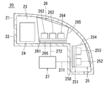
- FIG. 1 is a schematic diagram illustrating a configuration of a lamp device including a light blocking member according to an embodiment of the present disclosure, which is mounted on a front right side of a vehicle.
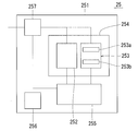
- FIG. 2 is a schematic diagram showing a configuration of a first sensor module arranged in the lamp device shown in FIG.
- FIG. 3 is a schematic diagram illustrating a configuration of a head-up display including a light blocking member according to an embodiment of the present disclosure.
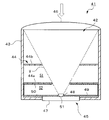
- FIG. 4 is a schematic diagram illustrating a configuration of a radiation thermometer including the light blocking member according to the embodiment of the present disclosure.
- FIG. 5 is a graph showing the measurement results of the reflectance in the example.
- the light-shielding member of the present embodiment is made of an aluminum oxide ceramic containing a titanium oxide represented by a composition formula of TiO 2-x (1 ⁇ x ⁇ 2), and includes a total of Fe, Ni, Co, Mn, and Cr. Content is 260 mass ppm or less. According to such a configuration, the reflectance is low over a wide wavelength range. In addition, the ultraviolet light (UV) absorbing effect of the oxide of titanium can suppress deterioration due to sunlight and protect the peripheral members of the light-shielding member, so that long-term use is possible.
- UV ultraviolet light
- the photocatalytic effect of the oxide of titanium can be exerted to remove stains on the peripheral members of the light-shielding member, and an antifouling effect can be obtained, so that long-term use is possible.
- the configuration of the light shielding member of the present embodiment will be specifically described.
- the aluminum oxide ceramics of all components 100% by mass constituting the ceramics, aluminum oxide content in terms of Al to Al 2 O 3 is at that of the ceramic is 90 mass% or more.
- the oxide of titanium represented by the composition formula TiO 2-x (1 ⁇ x ⁇ 2 ) is obtained by reducing titanium oxide (TiO 2 ).
- the crystal phase of the titanium oxide may be rutile type titanium oxide. Further, the total content of Fe, Ni, Co, Mn and Cr may be 170 mass ppm or less.
- the light-shielding member of the present embodiment exhibits a black color having a sufficiently low reflectance for light in a relatively wide wavelength range.
- the lightness index L * in the CIE1976L * a * b * color space is 48 or less, and the chromaticness indices a * and b * are -2 to 5 and -10 to 0, respectively.
- the value of the lightness index L * and the values of the chromaticness indices a * and b * in the CIE1976L * a * b * color space can be determined in accordance with JIS Z8722: 2009.
- a spectral color difference meter (NF777 manufactured by Nippon Denshoku Industries Co., Ltd. or its successor) may be used, and the measurement conditions may be such that the light source is CIE standard light source D65 and the viewing angle is 2 °.
- the maximum value Rmax of the reflectance over the wavelength range of 250 nm to 2500 nm is 24% or less
- ⁇ R which is the difference between the maximum value Rmax and the minimum value Rmin, is 15.3% or less. That is, the light-shielding member of the present embodiment has a low reflectance in a wavelength range of 250 nm to 2500 nm and a small variation in the wavelength distribution of the light intensity of the reflected light with respect to the irradiation light.
- the light shielding member of the present embodiment has a uniformly low reflectance over such a wide wavelength range.
- the content of the titanium oxide represented by the composition formula TiO 2-x (1 ⁇ x ⁇ 2) is, for example, 0.1% of 100% by mass of all components constituting the ceramic. 5 mass% or more and 4 mass% or less.
- the content of the titanium oxide is in the above-described range, a black color having a low reflectance with sufficiently low saturation can be obtained, and the volume resistivity at room temperature (5 to 35 ° C.) can be reduced. It has electrical insulation of 10 9 ⁇ ⁇ m or more.
- the volume specific resistance of the light shielding member of the present embodiment may be, for example, 10 8 ⁇ ⁇ m or more at 200 ° C.
- the volume resistivity decreases as the temperature increases, but the light-shielding member of the present embodiment has insulating properties even at a high temperature of 200 ° C.
- the volume resistivity can be determined in accordance with JIS C 2141: 1992.
- the upper limit of the volume resistivity is not particularly limited.
- the content of the titanium oxide in the aluminum oxide ceramic forming the light shielding member is 0.5% by mass or more, the aluminum oxide ceramic is inexpensive and the content of titanium oxide is 0.5% by mass. It is possible to obtain a high dielectric constant equivalent to that of high-purity and expensive aluminum oxide ceramics of less than mass%.
- the light shielding member may not contain aluminum titanate.
- Whether or not the light-shielding member contains aluminum titanate may be determined by comparing an X-ray chart obtained using an X-ray diffractometer (XRD) with a JCPDS card (No. 00-041-0258).
- the total content of Fe, Ni, Co, Mn and Cr is 260 mass ppm or less, that is, the content of Cr alone is 260 mass ppm at the maximum.
- Cr is contained in alumina, light having a wavelength of 700 nm or more and less than 780 nm (hereinafter also referred to as short wavelength light) or light having a wavelength of 780 nm or more and less than 1590 nm (hereinafter referred to as long wavelength light)
- the reflectance of the light-shielding member of the present embodiment is small in the short wavelength region and the long wavelength region because the Cr content is small.
- the Cr content of the light-shielding member is 40 mass ppm or less, the reflectance for light in a relatively wide wavelength range is sufficiently low.
- the Fe content in the light-shielding member is 100 mass ppm or less, an increase in reflectance due to discoloration can be further suppressed, so that the reflectance in the visible light region and the (near) infrared region becomes lower.
- the Ni content in the light shielding member is 10 mass ppm or less, the Co content is 5 mass ppm or less, or the Mn content is 100 mass ppm or less, the change in mechanical strength and electrical characteristics is small. .
- the light-shielding member may include oxides of silicon, calcium, and magnesium in a grain boundary phase that binds aluminum oxide crystal grains.
- the total content of the oxides of silicon, calcium and magnesium is, for example, 2% by mass or more and 4% by mass or less of 100% by mass of all components constituting the ceramics.
- the content of the oxides of calcium and magnesium is 10% by mass or more and 30% by mass or less, and the balance is It may be an oxide of silicon.
- the light-blocking member has a volume resistivity at room temperature of 10 11 ⁇ ⁇ m or more, or 10 12 ⁇ ⁇ m or more.
- crystal phase of the titanium oxide in the light-shielding member can be identified by XRD, and the value of x may be determined using a transmission electron microscope (TEM).
- the contents of aluminum, silicon, calcium, magnesium, and titanium in terms of oxides were determined using an X-ray fluorescence spectrometer (XRF) or an inductively coupled plasma (ICP) emission spectrometer (ICP).
- XRF X-ray fluorescence spectrometer
- ICP inductively coupled plasma
- SiO 2 SiO 2
- CaO CaO
- MgO magnesium oxide
- TiO 2-x (1 ⁇ x ⁇ 2).
- the contents of Fe, Ni, Co, Mn, and Cr may be determined using a glow discharge mass spectrometer (GDMS).
- GDMS glow discharge mass spectrometer
- the light shielding member of the present embodiment may have a portion where the average value of the skewness Rsk is 0.04 or more and 0.45 or less. When the light blocking member has such a portion, the reflectance is low. Note that the average value of all the skewnesses Rsk in the light shielding member may be 0.04 or more and 0.45 or less.
- the light-shielding member of the present embodiment may have a portion where the average value of the Kurtosis Rku is 4.1 or more and 6.5 or less. When the light blocking member has such a portion, the reflectance is low.
- the average value of all kurtosis Rku in the light shielding member may be 4.1 or more and 6.5 or less.
- the light shielding member of the present embodiment may have a portion where the average value of the arithmetic average roughness Ra is 1 ⁇ m or more and 2 ⁇ m or less.
- the average value of all arithmetic average roughnesses Ra in the light shielding member may be 1 ⁇ m or more and 2 ⁇ m or less.
- Skewness Rsk, Kurtosis Rku, and arithmetic average roughness Ra can be determined by using, for example, a laser microscope (VK-9510, manufactured by Keyence Corporation) in accordance with JIS B # 0601: 2001.
- the measurement conditions were as follows: the measurement mode was color super-depth, the measurement magnification was 400 times, the measurement range was 698 ⁇ m ⁇ 522 ⁇ m, the measurement pitch was 0.05 ⁇ m, the ⁇ s contour curve filter was 2.5 ⁇ m, and the ⁇ c contour curve filter was 0.08 mm.
- the average value of the measured values obtained from the eight measurement ranges may be the average value of the skewness Rsk, the Kurtosis Rku, and the arithmetic average roughness Ra.
- the aluminum oxide ceramic may have a light-shielding surface, and the color difference ⁇ * Eab of the light-shielding surface in the CIE1976L * a * b * color space may be 4.5 or less.
- the color difference ⁇ * Eab is an index indicating a variation in color tone, and is represented by the following equation (1).
- ⁇ E * ab [( ⁇ L *) 2 + ( ⁇ a *) 2 + ( ⁇ b *) 2 ] 1/2 (1)
- ⁇ L * is the difference between the lightness index L 1 * of the first measurement target point on the light shielding surface and the lightness index L 2 * of the second measurement target point
- ⁇ a * is the chromaticness index of the first measurement target point on the light shielding surface.
- the difference between a 1 * and the brightness index a 2 * of the second measurement point, ⁇ b * is the chromaticity index b 1 * of the first measurement point on the light-shielding surface and the brightness index b 2 * of the second measurement point. Is the difference.
- the variation coefficient of the lightness index L * in the CIE1976L * a * b * color space of the light-shielding surface of the aluminum oxide ceramic may be 0.02 or less (excluding 0).
- the variation coefficient of the lightness index L * is within the above range, the light-shielding surface is hardly discolored even when repeatedly irradiated with light, so that the light-shielding surface does not easily change over time.
- the average value of the lightness index L * of the light-shielding surface is, for example, 48 or less.
- the value of the lightness index L * and the values of the chromaticness indices a * and b * in the CIE1976 L * a * b * color space of the light-shielding surface can be obtained by the same method as described above.
- the aluminum oxide ceramic may have open pores, and the sphericity of the open pore may be 0.1 or more.
- the average value of the equivalent circle diameter of the open pores is, for example, 4 ⁇ m or more and 6 ⁇ m or less.
- the porosity of the open pores is 3 area% or more and 6 area% or less.
- the average particle diameter D 50 was polished holding member in the cast iron plate with diamond abrasive grains of 3 [mu] m, an average particle diameter D 50 0. Polishing is performed on a tin platen using diamond abrasive grains of 5 ⁇ m to obtain a measurement surface.
- an average part of the measurement surface is selected and photographed with a CCD camera at a magnification of 100 using an optical microscope.
- image analysis software for example, Win ROOF, manufactured by Mitani Corporation
- the threshold value of the equivalent circle diameter of the open pores is 0.8 ⁇ m, and the equivalent circle diameter less than 0.8 ⁇ m is not analyzed.
- the skewness of the circle equivalent diameter of the open pore may be obtained by using a function SKEW provided in Excel (registered trademark, Microsoft Corporation).
- the shape of the light shielding member is, for example, a plate shape (light shielding plate).
- the shape of the light blocking member is not limited to the illustrated shape.
- powders of aluminum oxide, silicon oxide, calcium carbonate, magnesium hydroxide and titanium oxide are prepared.
- the total content of the powders of calcium carbonate, magnesium hydroxide, and silicon oxide is, for example, 6.5% by mass or more and 12.9% by mass or less of the total 100% by mass of the powder.
- the content of the powder of calcium carbonate, magnesium hydroxide and silicon oxide is 17.8% by mass or more and 53.4% by mass or less of the total of 100% by mass of these powders.
- the content of the magnesium hydroxide powder is 14.4% by mass or more and 43.2% by mass or less, and the remainder is silicon oxide powder.
- the content of the titanium oxide powder is, for example, 0.5% by mass or more and 4% by mass or less of the total 100% by mass of each powder of aluminum oxide, silicon oxide, calcium carbonate, magnesium hydroxide, and titanium oxide;
- the balance is aluminum oxide powder.
- the content of magnesium hydroxide is preferably 30% by mass or more and 44% by mass or less of the content of titanium oxide.
- the content of magnesium hydroxide is in the above range, generation of anorthite and mullite which are likely to occur in a reduction treatment described later is suppressed. Since anorthite and mullite have different average coefficients of linear expansion from aluminum oxide, if the formation of these compounds is suppressed, cracks may occur even when the light-shielding member is used in an environment that is repeatedly exposed to heating and cooling. Is less likely to occur.
- a pulverizer such as a barrel mill, a rotary mill, a vibration mill, a bead mill, an agitator mill, an atomizer, and an attritor to obtain a slurry.
- a solvent, an organic binder such as polyvinyl alcohol (PVA) in an amount of 1 part by mass to 1.5 parts by mass with respect to 100 parts by mass of the solvent, and 0.1 part by mass with respect to 100 parts by mass of the solvent Parts by mass and 0.5 part by mass or less of the dispersant are put into the grinder together.
- PVA polyvinyl alcohol
- the obtained slurry is subjected to a demagnetization treatment and then spray-dried to obtain granules.
- Fe, Ni and Co which are ferromagnetic metals, are removed.
- the content of Fe, Ni, Co, Mn and Cr in the light-shielding member is affected by the wear of the stainless steel member used in the crusher.
- a stainless steel member that is worn by long-term use may be replaced with a titanium component that easily forms a passivation film on its surface, or a titanium-based film such as TiN, TiCN, TiC, TiAlN, TiAlCN, or TiAlO, or a non-titanium-based material.
- the surface of the stainless steel member may be coated with crystalline hard carbon (DLC).
- the light-shielding member having a total content of Fe, Ni, Co, Mn, and Cr of 260 mass ppm or less can be obtained by replacing or coating the stainless steel member.
- the granules are molded by a dry pressure molding method or a cold isostatic pressing method (CIP) and then subjected to cutting to obtain a molded body.
- the molding pressure may be, for example, 1500 MPa or more and 4000 MPa or less.
- the obtained compact is fired in an air (oxidizing) atmosphere at a temperature of 1500 ° C. or higher and 1700 ° C. or lower for a predetermined period of time to obtain a sintered body.
- the sintered body obtained by the above-described method is used as a reducing atmosphere, for example, in a mixed gas having a nitrogen: hydrogen ratio of 87 to 90% by volume: 10 to 13% by volume, from 1300 ° C. to 1400 ° C.
- a mixed gas having a nitrogen: hydrogen ratio of 87 to 90% by volume: 10 to 13% by volume from 1300 ° C. to 1400 ° C.
- the content of the titanium oxide powder is determined by changing the content of aluminum oxide, silicon oxide, calcium carbonate, and hydroxide.
- the total content of the magnesium and titanium oxide powders may be 1.8% by mass to 3% by mass of the total 100% by mass, and may be maintained at a temperature of 1330 ° C to 1400 ° C for 1 hour to 2 hours.
- the content of the titanium oxide powder must be reduced. 1.8 mass% to 3 mass% of the total 100 mass% of each powder of aluminum, silicon oxide, calcium carbonate, magnesium hydroxide, and titanium oxide, at 1350 ° C to 1400 ° C for 1 hour to 2 It may be held for less than an hour.
- the light-shielding member of the present embodiment described above has a low reflectance in the visible light region and the (near) infrared region and can be used for a long period of time.
- a lamp device and a head-up display will be described as an example of a vehicle-mounted optical device including the light-blocking member according to the present embodiment, and the description will be sequentially given with reference to the drawings.
- the in-vehicle optical device according to the present disclosure may include any configuration that is not illustrated in the drawings referred to. Further, the dimensions of the components in the drawings do not faithfully represent the dimensions, dimensional ratios, and the like of the actual components.
- Lamp device In the following description, a configuration in which the lamp device is mounted on the right front of the vehicle will be described as an example, but the lamp device of the present disclosure is not limited to a configuration mounted on the right front of the vehicle as long as it has the function.
- a lamp device 20 includes a light-transmitting cover 21 located in a traveling direction of a vehicle, a housing 22 located on the opposite side of the light-transmitting cover 21, and a light-transmitting cover 21. And a headlight 24, a first sensor module 25, and a second sensor module 26 which are respectively located inside a lamp room 23 surrounded by the housing 22.
- the headlight 24 includes an optical system component including at least one of a lens and a reflector.
- the light emitted from the headlight 24 passes through the translucent cover 21 and illuminates the right front of the vehicle. Since the lamp device 20 includes such a headlight 24, it functions as a headlight.
- the first sensor module 25 includes a first substrate 251 (support member).
- the first substrate 251 supports a first visible light camera 252, a first LiDAR (Light Detection and Ranging) sensor 253, and a first light shielding member 254 (shielding member). Further, as shown in FIG. , A communication unit 256 and a power supply unit 257.
- the first substrate 251 is a substrate on which a sensor circuit including the first visible light camera 252, the first LiDAR sensor 253, the control unit 255, the communication unit 256, and the power supply unit 257 is mounted.
- a plurality of sensors (the first visible light camera 252 and the first LiDAR sensor 253) having different detection methods, a first light-blocking member 254 which is a cylindrical hollow member surrounding these sensors, and a circuit for operating these sensors are modularized on the first substrate 251.
- the first visible light camera 252 captures an image of the right side of the vehicle. That is, the first visible light camera 252 is a sensor that detects information on the right side of the vehicle.
- the first LiDAR sensor 253 includes a light emitting unit 253a that emits infrared light and a light receiving unit 253b that detects reflected light that is reflected by the infrared light hitting an object present on the right side of the vehicle.
- the first LiDAR sensor 253 can calculate the distance to the object based on the time from emitting infrared light in a certain direction to detecting reflected light from the object.
- information on the shape of the object can be obtained by collecting and analyzing the measured values of the distance in association with the detected position.
- information such as the material of the object associated with the reflection can be obtained based on the difference between the wavelengths of the emitted light and the reflected light.
- information on the color of the target object (such as a white line on the road surface) can be obtained based on the difference in the reflectance of the reflected light. That is, the first LiDAR sensor 253 can obtain various information on the right side of the vehicle by a method different from that of the first visible light camera 252.
- the first sensor module 25 includes a first actuator 258 (an example of an adjustment mechanism) coupled to the first substrate 251.
- the first actuator 258 adjusts at least one of the position and the posture of the first substrate 251 with respect to the vehicle.
- the second sensor module 26 includes the second substrate 261.
- the second substrate 261 supports the second visible light camera 262, the second LiDAR sensor 263, the millimeter wave radar 264, and the second light shielding member 265 which is a cylindrical hollow member surrounding these, all of which are not shown.
- the control unit, the communication unit, and the power supply unit are further supported.
- the functions of the second visible light camera 262 and the second LiDAR sensor 263 are the same as the functions of the first visible light camera 252 and the first LiDAR sensor 253, respectively, and a description thereof will be omitted.
- the millimeter-wave radar 264 includes a transmitting unit that transmits a millimeter wave and a receiving unit that receives a reflected wave that has been reflected by at least an object in which the millimeter wave hits the right front of the vehicle.
- the frequency of the millimeter wave is, for example, 24 GHz, 26 GHz, 76 GHz, or 79 GHz.
- the millimeter-wave radar 264 can determine the distance to the object based on the time from when the infrared light is emitted in a certain direction to when the reflected light from the object is detected. In addition, by collecting and analyzing the distance measurement values in association with the detection position, information relating to the movement of the object can be obtained. That is, the millimeter wave radar 264 can obtain information on the right front of the vehicle by a method different from that of the second visible light camera 262 or the second LiDAR sensor 263.
- the second sensor module 26 includes a second actuator 266 (an example of an adjustment mechanism) coupled to the second substrate 261.
- the second actuator 266 adjusts at least one of the position and the posture of the second substrate 261 with respect to the vehicle.
- the lamp device 20 also includes a signal processing unit 27 located outside the lamp room 23.
- the signal processing unit 27 is configured to output a first drive signal 271 for driving the first actuator 258 and a second drive signal 272 for driving the second actuator 266.
- the first drive signal 271 includes at least one of the position and the posture of the first actuator 258, and the second drive signal 272 includes the information of at least one of the position and the posture of the second actuator 266. .
- the light-shielding member of the present embodiment has a high electric resistance and has a black color tone on the surface, so that light rays scattered around the first sensor module 25 or the second sensor module 26 can be blocked. Highly accurate information can be obtained.
- the lamp device 20 includes a light-blocking member located around the headlight 24.
- the light blocking member located around the headlight 24 is formed of the light blocking member of the present embodiment.
- the light blocking member of the present embodiment may be for a light source element of a headlight. According to such a configuration, stray light can be removed by the low reflectance of the light shielding member of the present embodiment, so that unnecessary reflection or scattering on the optical path can be reduced, and noise of a projected image can be reduced. .
- deterioration due to sunlight can be suppressed by the UV absorption effect of the oxide of titanium, and the headlight 24 can be protected, so that long-term use is possible.
- the lamp device 20 includes a light shielding member attached to the first visible light camera 252 and a light shielding member attached to the second visible light camera 262.
- at least one of the light shielding member attached to the first visible light camera 252 and the light shielding member attached to the second visible light camera 262 is made of the light shielding member of the present embodiment.
- the light blocking member of the present embodiment may be for a vehicle-mounted camera. According to such a configuration, noise of a projected image can be reduced by the low reflectance of the light shielding member of the present embodiment in the visible light region and the (near) infrared region.
- the sensitivity can be maintained by preventing contamination near the lens by the photocatalytic effect of the oxide of titanium.
- the head-up display 30 includes an in-vehicle projector module 31, a reflection mirror 32, a microlens array 33, a convex lens 34, a combiner 35.
- the vehicle-mounted projector module 31 projects an image in the direction of arrow a.
- the in-vehicle projector module 31 includes an optical and MEMS (Micro Electro Mechanical Systems) unit and an RGB light source module housed in the optical and MEMS unit.
- MEMS Micro Electro Mechanical Systems
- the reflection mirror 32 reflects the image projected from the vehicle-mounted projector module 31 toward the microlens array 33.
- the micro lens array 33 functions as an intermediate image screen.
- the convex lens 34 is adjacent to the microlens array 33 and convex toward the combiner 35, and functions as a field lens.
- the combiner 35 reflects the image enlarged by the convex lens 34 toward the driver's eyes.
- the head-up display 30 further includes the following configuration in addition to the configuration described above. That is, the head-up display 30 includes a lens holding member 36 that holds the microlens array 33 and the convex lens 34 as a holding member for an optical product. Further, the head-up display 30 includes a light shielding member attached to the reflection mirror 32 and the lens holding member 36, respectively.
- the light shielding member attached to the reflection mirror 32 and the light shielding member attached to the lens holding member 36 is made of the light shielding member of the present embodiment.
- the light blocking member of the present embodiment may be for a head-up display. According to such a configuration, noise of a projected image can be reduced by a low reflectance over a wide wavelength range of the light shielding member of the present embodiment.
- the antifouling effect of the photocatalytic effect of the oxide of titanium enables long-term use.
- the light-shielding member of the present embodiment can also be used for a radiation thermometer.
- a radiation thermometer according to an embodiment of the present disclosure will be described with reference to the drawings.
- the radiation thermometer shown in FIG. 4 is a thermometer used at a site where the temperature of the environment is not constant and a large temperature change occurs.
- the radiation thermometer can measure the temperature of the measurement target in a non-contact manner based on the intensity of infrared rays radiated from the measurement target.
- the radiation thermometer shown in FIG. 4 includes an infrared detector 41 and a temperature calculator (not shown) that calculates the temperature of the measurement target based on the electric signal output from the infrared detector 41.
- the infrared detector 41 includes a metal barrel 43 having an infrared inlet 42 on the distal end side, a diaphragm mechanism 44 provided in the barrel 43, and an infrared sensor provided on the base end side of the barrel 43. 45.
- the temperature calculation unit TC is, for example, a computer including a CPU, a memory, an A / D / D / A converter, and the like, and executes a program stored in the memory.
- an electric signal output in accordance with the amount of infrared light incident by the infrared sensor 45 is input to the temperature calculation unit TC, and the temperature calculation unit TC converts the amount of infrared light indicated by the electric signal into temperature by a predetermined conversion formula. Convert and output the value.
- the lens barrel 43 has a cylindrical shape, and the distal end side is open to form the infrared inlet 42, and the base end side is closed except for a portion where the infrared sensor 45 is attached. Further, a convex lens 46 is mounted so as to close the infrared inlet 42.
- the aperture mechanism 44 has a first aperture 44a provided on the base end side of the lens barrel 43 and a second aperture 44b provided on the tip side of the lens barrel 43.
- the first stop 44a and the second stop 44b are provided perpendicular to the axial direction of the lens barrel 43, and the first stop 44a has a smaller opening diameter than the second stop 44b. That is, the first aperture 44a limits the field of view V of the infrared sensor 45, and determines the size of the field of view V, which is a range in which infrared rays emitted from the measurement target can enter via the lens 46.
- the space on the distal end side of the first stop 44a is referred to as an inlet side space S1
- the space on the proximal end side of the first stop 44a is referred to as a sensor side space S2.
- the infrared sensor 45 includes a sensor element 51 housed in a cylindrical housing 47 and an optical filter 48 provided on the top surface of the housing 47. It is arranged on the base end side of the lens barrel 43 so as to be located above and facing the infrared inlet 42.
- the sensor element 51 is a thermal element that detects a temperature change when absorbing infrared rays as a change in electromotive force.
- a thermopile element in which a large number of thermocouples are arranged in series and thinned is used.
- the optical filter 48 is a bandpass filter that allows only light (electromagnetic waves) in a predetermined wavelength band to pass.
- a filter that passes only infrared light having a wavelength band of 8 ⁇ m to 14 ⁇ m is used, and only the infrared light that has passed through the optical filter 48 is received by the sensor element 51. Since this wavelength band (8 ⁇ m to 14 ⁇ m) is a band where the absorption by the atmosphere is small, when measuring the temperature, the influence of the absorption by the atmosphere interposed between the object to be measured and the infrared sensor 45 is suppressed, and the measurement with high accuracy is performed. can do.
- a reflection structure 49 or an infrared absorption structure 50 is provided on a surface of the lens barrel 43 that forms the sensor-side space S2.
- the reflection structure 49 is provided on the inner peripheral surface of the lens barrel 43 in contact with the sensor-side space S2, and on the surface of the partition plate forming the first stop 44a, which faces the infrared sensor 45.
- the reflection structure 49 is a reflection film formed of a resin or the like containing a metal filler, and the amount of incident infrared rays reflected can be made larger than the amount absorbed.
- the infrared absorption structure 50 is a plate-shaped light-shielding member according to the present disclosure, which is laid so as to cover the entire top surface of the infrared sensor 45 except for the optical filter 48 and the entire inner end surface on the base end side of the lens barrel 43. . That is, the infrared absorbing structure 50 is formed on all of the portion facing the first stop 44a except the optical filter 48. The amount of infrared rays incident on the infrared absorbing structure 50 can be absorbed more than the amount of reflected light.
- the temperature of the infrared detector itself constituting the radiation thermometer fluctuates greatly, so that the intensity of infrared radiation radiated from the inner surface on the distal end side of the lens barrel 43 is increased. Becomes difficult to be kept constant.
- infrared light having such a change in intensity is incident on the infrared sensor 45, the measured temperature tends to drift.
- the case where the light shielding member is used for the on-vehicle optical device and the radiation thermometer has been described as an example. It can be used for other purposes as well.
- Other applications include, for example, electronic equipment, medical and physicochemical equipment, and the like. Specific examples include medical equipment such as CT scanning, and analyzers such as a transmission electron microscope (TEM).
- TEM transmission electron microscope
- the application of the light shielding member is not limited to the illustrated one.
- the granules were formed by cold isostatic pressing (CIP) and then subjected to cutting to obtain a formed body. Thereafter, the obtained molded body was kept in an air (oxidizing) atmosphere at a temperature of 1570 ° C. for 2 hours to obtain a sintered body. Next, the surface of the sintered body was polished using a vibration barrel polishing machine.
- CIP cold isostatic pressing
- the sintered body obtained by the above-described method is kept at a temperature of 1350 ° C. for 1 hour and 30 minutes in a reducing atmosphere (a mixed gas having a nitrogen: hydrogen ratio of 88.5% by volume: 11.5% by volume).
- a mixed gas having a nitrogen: hydrogen ratio of 88.5% by volume: 11.5% by volume As a result, the sample No. 1-4 were obtained.
- Each of the obtained samples was identified using XRD.
- the value of x in TiO 2-x was determined using a transmission electron microscope (TEM). Further, the contents of the elements constituting each sample were determined using XRF, and converted into the identified components. Further, the contents of the trace components Fe, Ni, Co, Mn and Cr were determined using a glow discharge mass spectrometer (GDMS). Table 1 shows the results. Each sample contains inevitable impurities as components not shown in Table 1.
- the reflectance in the wavelength range of 250 nm to 2500 nm was determined using an ultraviolet-visible-near-infrared spectrophotometer (V-670, manufactured by JASCO Corporation), and the measured values were graphed. 5 is shown. Further, ⁇ R was calculated from the minimum value Rmin and the maximum value Rmax of the reflectance in the above-mentioned region of each sample. Table 1 shows the minimum value Rmin, the maximum value Rmax, and ⁇ R of the reflectance.
- the integrating sphere unit used for the measurement of the reflectance is ISN-723
- the reference light source is a deuterium lamp in a wavelength region of 250 nm to 360 nm
- the halogen lamp is a region in a wavelength range of 360 nm to 2500 nm.
- the mode was total reflectance
- the data acquisition interval was 1.0 nm
- the UV / Vis bandwidth was 5.0 nm
- the NIR bandwidth was 20.0 nm.
- Sample Nos. 1 to 3 are sample Nos. Rmax and ⁇ R were smaller than 4. From these results, it was made of an aluminum oxide ceramic containing a titanium oxide represented by a composition formula of TiO 2-x (1 ⁇ x ⁇ 2), and the total content of Fe, Ni, Co, Mn and Cr was 260 It was found that when the mass was ppm or less, the reflectance was low in the wavelength range of 250 nm to 2500 nm, and the variation in the wavelength distribution of the light intensity of the reflected light with respect to the irradiation light was small.
- sample no. No. 1 is more suitable for use as described above because the difference ⁇ R in the reflectance in the above-mentioned region is 6.2%.
Landscapes
- Engineering & Computer Science (AREA)
- Chemical & Material Sciences (AREA)
- Physics & Mathematics (AREA)
- General Physics & Mathematics (AREA)
- Ceramic Engineering (AREA)
- Organic Chemistry (AREA)
- Structural Engineering (AREA)
- Materials Engineering (AREA)
- Optics & Photonics (AREA)
- Manufacturing & Machinery (AREA)
- Computer Networks & Wireless Communication (AREA)
- Remote Sensing (AREA)
- Radar, Positioning & Navigation (AREA)
- Spectroscopy & Molecular Physics (AREA)
- Mechanical Engineering (AREA)
- General Engineering & Computer Science (AREA)
- Composite Materials (AREA)
- Optical Elements Other Than Lenses (AREA)
- Compositions Of Oxide Ceramics (AREA)
- Photometry And Measurement Of Optical Pulse Characteristics (AREA)
Abstract
本開示の遮光部材は、組成式がTiO2-x(1≦x<2)として示されるチタンの酸化物を含む酸化アルミニウム質セラミックスからなり、Fe、Ni、Co、MnおよびCrの合計の含有量が260質量ppm以下である。
Description
本開示は、遮光部材に関する。
特許文献1には、黒色セラミックスの組成の一例として、Al2O3、Si、Ti、Mn、Fe、Crなどが記載されており、黒色にするための着色材として、Fe、Cr、Co、Mn、Ni、Cuなどが使われることが記載されている。
本開示の遮光部材は、組成式がTiO2-x(1≦x<2)として示されるチタンの酸化物を含む酸化アルミニウム質セラミックスからなり、Fe、Ni、Co、MnおよびCrの合計の含有量が260質量ppm以下である。
<遮光部材>
以下、本開示の実施形態に係る遮光部材について詳細に説明する。
本実施形態の遮光部材は、組成式がTiO2-x(1≦x<2)として示されるチタンの酸化物を含む酸化アルミニウム質セラミックスからなり、Fe、Ni、Co、MnおよびCrの合計の含有量が260質量ppm以下である。このような構成によれば、広い波長範囲にわたって反射率が低くなる。また、チタンの酸化物の紫外線(UV)吸収効果によって日光による劣化を抑制することができ、遮光部材の周辺部材を保護することができるので、長期使用が可能となる。さらに、日光を浴びるとチタンの酸化物の光触媒効果が発現して遮光部材の周辺部材の汚れを除去することができ、防汚効果も得られるので、長期使用が可能となる。以下、本実施形態の遮光部材の構成について具体的に説明する。
以下、本開示の実施形態に係る遮光部材について詳細に説明する。
本実施形態の遮光部材は、組成式がTiO2-x(1≦x<2)として示されるチタンの酸化物を含む酸化アルミニウム質セラミックスからなり、Fe、Ni、Co、MnおよびCrの合計の含有量が260質量ppm以下である。このような構成によれば、広い波長範囲にわたって反射率が低くなる。また、チタンの酸化物の紫外線(UV)吸収効果によって日光による劣化を抑制することができ、遮光部材の周辺部材を保護することができるので、長期使用が可能となる。さらに、日光を浴びるとチタンの酸化物の光触媒効果が発現して遮光部材の周辺部材の汚れを除去することができ、防汚効果も得られるので、長期使用が可能となる。以下、本実施形態の遮光部材の構成について具体的に説明する。
酸化アルミニウム質セラミックスとは、セラミックスを構成する全成分100質量%のうち、AlをAl2O3に換算した酸化アルミニウムの含有量が90質量%以上であるセラミックスのことである。また、組成式がTiO2-x(1≦x<2)として示されるチタンの酸化物とは、酸化チタン(TiO2)が還元されたものである。チタンの酸化物の結晶相は、ルチル型酸化チタンであってもよい。また、Fe、Ni、Co、MnおよびCrの合計の含有量は、170質量ppm以下であってもよい。
本実施形態の遮光部材は、比較的広い波長範囲の光に対して反射率が十分に低い黒色を呈する。具体的には、CIE1976L*a*b*色空間における明度指数L*が48以下であり、クロマティクネス指数a*、b*がそれぞれ-2以上5以下、-10以上0以下である。CIE1976L*a*b*色空間における明度指数L*の値、クロマティクネス指数a*およびb*の値は、JIS Z 8722:2009に準拠して求めることができる。例えば、分光色差計(日本電色工業(株)製NF777またはその後継機種)を用い、測定条件としては、光源をCIE標準光源D65、視野角度を2°に設定すればよい。
本実施形態の遮光部材は、波長250nm~2500nmにわたる反射率の最大値Rmaxが24%以下であり、最大値Rmaxと最小値Rminとの差であるΔRが15.3%以下である。すなわち、本実施形態の遮光部材は、波長250nm~2500nmの範囲において、反射率が低く、照射光に対する反射光の光強度の波長分布のばらつきが小さい。本実施形態の遮光部材は、このように広い波長範囲にわたって反射率が一様に低くなっている。
本実施形態の遮光部材において、組成式がTiO2-x(1≦x<2)として示されるチタンの酸化物の含有量は、セラミックスを構成する全成分100質量%のうち、例えば、0.5質量%以上4質量%以下である。チタンの酸化物の含有量が前述した範囲であるときには、彩度が十分に抑制された反射率の低い黒色の色味とすることができるとともに、室温(5~35℃)における体積固有抵抗が109Ω・m以上の電気的絶縁性を有する。また、より絶縁性を高めるという観点からは、本実施形態の遮光部材の体積固有抵抗は、例えば、200℃にて108Ω・m以上であってもよい。通常、温度が高くなると体積固有抵抗は低下するが、本実施形態の遮光部材は、200℃の高温においても絶縁性を有する。ここで、体積固有抵抗は、JIS C 2141:1992に準拠して求めることができる。なお、体積固有抵抗の上限値は、特に限定されない。
また、遮光部材を形成する酸化アルミニウム質セラミックスにおける上記チタンの酸化物の含有量が0.5質量%以上である場合、この酸化アルミニウム質セラミックスは安価であり、酸化チタンの含有量が0.5質量%未満の高純度かつ高価な酸化アルミニウム質セラミックスの誘電率と同等の高い誘電率を得ることができる。
遮光部材は、チタン酸アルミニウムを含んでいなくてもよい。このような構成を満たすときには、酸化アルミニウムに対する線膨張係数の差が大きいチタン酸アルミニウムが遮光部材中に存在しないことから、昇温および冷却が繰り返されても微小なクラックが発生しにくい。遮光部材がチタン酸アルミニウムを含んでいるか否かは、X線回折装置(XRD)を用いて得られるX線チャートを、JCPDSカード(No.00-041-0258)と照合すればよい。
本実施形態の遮光部材は、Fe、Ni、Co、MnおよびCrの合計の含有量が260質量ppm以下、すなわちCr単独の含有量が最大でも260質量ppmである。アルミナにCrを含有させた際には、波長が700nm以上780nm未満の領域の光(以降、短波長領域光ともいう)や、波長が780nm以上1590nm未満の領域の光(以降、長波長領域光ともいう)の反射率が大きくなりやすいが、本実施形態の遮光部材は、Crの含有量が少ないことから、短波長領域および長波長領域における反射率が小さい。
遮光部材においてCrの含有量が40質量ppm以下であれば、比較的広い波長範囲の光に対する反射率が十分に低くなる。
また、遮光部材におけるFeの含有量が100質量ppm以下であれば、変色による反射率の増加をより抑制することができるため、可視光線領域および(近)赤外線領域での反射率がより低くなる。
また、遮光部材における、Niの含有量が10質量ppm以下、Coの含有量が5質量ppm以下またはMnの含有量が100質量ppm以下であれば、機械的強度や電気特性の変化が小さくなる。
遮光部材は、酸化アルミニウムの結晶粒子同士を結合する粒界相に、珪素、カルシウムおよびマグネシウムの酸化物を含んでいてもよい。ここで、珪素、カルシウムおよびマグネシウムの酸化物の含有量の合計は、セラミックスを構成する全成分100質量%のうち、例えば、2質量%以上4質量%以下である。また、珪素、カルシウムおよびマグネシウムの酸化物の含有量の合計を100質量%としたとき、カルシウムの酸化物およびマグネシウムの酸化物の含有量はそれぞれ10質量%以上30質量%以下であり、残部が珪素の酸化物であってもよい。珪素、カルシウムおよびマグネシウムの酸化物の含有量が上記範囲である場合、遮光部材は、室温における体積固有抵抗が1011Ω・m以上か、または1012Ω・m以上となる。
なお、遮光部材におけるチタンの酸化物の結晶相は、XRDによって同定することができ、xの値については、透過型電子顕微鏡(TEM)を用いて求めればよい。
また、アルミニウム、珪素、カルシウム、マグネシウムおよびチタンをそれぞれ酸化物に換算した含有量は、蛍光X線分析装置(XRF)またはICP(Inductively Coupled Plasma)発光分光分析装置(ICP)を用いて、各元素の含有量を求め、それぞれAl2O3、SiO2、CaO、MgOおよびTiO2-x(1≦x<2)に換算することで求められる。Fe、Ni、Co、MnおよびCrの含有量は、グロー放電質量分析装置(GDMS)を用いて求めればよい。
本実施形態の遮光部材は、スキューネスRskの平均値が0.04以上0.45以下である部分を有していてもよい。遮光部材がこのような部分を有しているときには、反射率が低くなる。なお、遮光部材におけるすべてのスキューネスRskの平均値が0.04以上0.45以下であってもよい。
また、本実施形態の遮光部材は、クルトシスRkuの平均値が4.1以上6.5以下である部分を有していてもよい。遮光部材がこのような部分を有しているときには、反射率が低くなる。なお、遮光部材におけるすべてのクルトシスRkuの平均値が4.1以上6.5以下であってもよい。
さらに、本実施形態の遮光部材は、算術平均粗さRaの平均値が1μm以上2μm以下である部分を有していてもよい。遮光部材がこのような部分を有しているときには、反射率が低くなる。なお、遮光部材におけるすべての算術平均粗さRaの平均値が1μm以上2μm以下であってもよい。
スキューネスRsk、クルトシスRkuおよび算術平均粗さRaは、JIS B 0601:2001に準拠し、例えば、レーザー顕微鏡((株)キーエンス社製(VK-9510))を用いて求めることができる。測定条件は、測定モードをカラー超深度、測定倍率を400倍、測定範囲を698μm×522μm、測定ピッチを0.05μm、λs輪郭曲線フィルタを2.5μm、λc輪郭曲線フィルタを0.08mmとし、上記測定範囲8箇所から得られる測定値の平均値を、スキューネスRsk、クルトシスRkuおよび算術平均粗さRaのそれぞれの平均値とすればよい。
酸化アルミニウム質セラミックスは遮光面を備え、遮光面のCIE1976L*a*b*色空間における色差Δ*Eabが4.5以下であってもよい。
色差Δ*Eabは、色調感のばらつきを示す指標であり、以下の式(1)で示される。
ΔE*ab=〔(ΔL*)2+(Δa*)2+(Δb*)2〕1/2 (1)
(ΔL*は、遮光面の第1測定対象点の明度指数L1*と第2測定対象点の明度指数L2*との差、Δa*は遮光面の第1測定対象点のクロマティクネス指数a1*と第2測定対象点の明度指数a2*との差、Δb*は遮光面の第1測定対象点のクロマティクネス指数b1*と第2測定対象点の明度指数b2*との差である。)
ΔE*ab=〔(ΔL*)2+(Δa*)2+(Δb*)2〕1/2 (1)
(ΔL*は、遮光面の第1測定対象点の明度指数L1*と第2測定対象点の明度指数L2*との差、Δa*は遮光面の第1測定対象点のクロマティクネス指数a1*と第2測定対象点の明度指数a2*との差、Δb*は遮光面の第1測定対象点のクロマティクネス指数b1*と第2測定対象点の明度指数b2*との差である。)
色差Δ*Eabが上記範囲であると、遮光面の色調感のばらつきが低減して、そのばらつきを視認しにくくなるので、商品価値が向上する。
また、酸化アルミニウム質セラミックスの遮光面のCIE1976L*a*b*色空間における明度指数L*の変動係数が0.02以下(但し、0を除く)であってもよい。
明度指数L*の変動係数が上記範囲であると、遮光面が繰り返して光の照射を受けても変色しにくい状態になっているので、経時変化しにくい。ここで、遮光面の明度指数L*の平均値は、例えば、48以下である。
なお、遮光面のCIE1976L*a*b*色空間における明度指数L*の値、クロマティクネス指数a*およびb*の値は、上述した方法と同じ方法で求めることができる。
また、酸化アルミニウム質セラミックスは、開気孔を有し、開気孔の円相当径の歪度が0.1以上であってもよい。
開気孔の円相当径の歪度が上記範囲であると、円相当径の分布が小さな方向に移動し、浮遊する金属粉や白色系の明色を呈する紛体が開気孔に侵入しにくくなるので、遮光面の色調感のばらつきが低減し、商品価値が向上する。
開気孔の円相当径の平均値は、例えば、4μm以上6μm以下である。また、開気孔の気孔率は、3面積%以上6面積%以下である。
開気孔の円相当径および気孔率を求めるには、まず、平均粒径D50が3μmのダイヤモンド砥粒を用いて鋳鉄製定盤にて保持部材を研磨した後、平均粒径D50が0.5μmのダイヤモンド砥粒を用いて錫定盤にて研磨して、測定面を得る。
そして、光学顕微鏡を用いて、倍率を100倍として、CCDカメラで、測定面のうち、平均的な部分を選択して撮影する。次に、撮影した画像のうち、1範囲当りの面積が2.27×102μmである範囲を4カ所設定して、画像解析ソフト(例えば、三谷商事(株)製、Win ROOF)を用いて解析することによって、開気孔の円相当径および気孔率を得ることができる。なお、解析するに当たり、開気孔の円相当径の閾値は、0.8μmとし、0.8μm未満の円相当径は解析の対象とはしない。
そして、開気孔の円相当径の歪度は、Excel(登録商標、Microsoft Corporation)に備えられている関数SKEWを用いて求めればよい。
遮光部材の形状としては、例えば、板状(遮光板)などが挙げられる。なお、遮光部材の形状は、例示した形状に限定されない。
(遮光部材の製造方法)
次に、本実施形態の遮光部材の製造方法の一例を説明する。
次に、本実施形態の遮光部材の製造方法の一例を説明する。
まず、酸化アルミニウム、酸化珪素、炭酸カルシウム、水酸化マグネシウムおよび酸化チタンの各粉末を準備する。
炭酸カルシウム、水酸化マグネシウムおよび酸化珪素の粉末の含有量の合計は、上記粉末の合計100質量%のうち、例えば、6.5質量%以上12.9質量%以下である。そして、炭酸カルシウム、水酸化マグネシウムおよび酸化珪素の粉末の含有量は、これら粉末の合計100質量%のうち、炭酸カルシウムの粉末の含有量は17.8質量%以上53.4質量%以下であり、水酸化マグネシウムの粉末の含有量は14.4質量%以上43.2質量%以下であり、残部が酸化珪素の粉末である。
酸化チタンの粉末の含有量は、酸化アルミニウム、酸化珪素、炭酸カルシウム、水酸化マグネシウムおよび酸化チタンの各粉末の合計100質量%のうち、例えば、0.5質量%以上4質量%以下であり、残部が酸化アルミニウムの粉末である。
特に、水酸化マグネシウムの含有量は、酸化チタンの含有量の30質量%以上44質量%以下であるとよい。水酸化マグネシウムの含有量が上記範囲であると、後述する還元処理で生じやすいアノーサイトおよびムライトの生成が抑制される。アノーサイトやムライトは酸化アルミニウムに対して平均線膨張率が異なっているため、これらの化合物の生成が抑制されると、繰り返して加熱および冷却に曝される環境で遮光部材が用いられてもクラックが生じにくくなる。
そして、これら粉末をバレルミル、回転ミル、振動ミル、ビーズミル、アジテーターミル、アトマイザー、アトライターなどの粉砕機によって湿式混合して粉砕し、スラリーを得る。なお、上記粉砕にあたっては、溶媒、この溶媒100質量部に対して1質量部以上1.5質量部以下のポリビニルアルコール(PVA)などの有機結合剤、溶媒100質量部に対して0.1質量部以上0.5質量部以下の分散剤を併せて粉砕機内に投入する。次に、得られたスラリーを脱磁処理した後、噴霧乾燥して、顆粒を得る。脱磁処理によって、強磁性金属であるFe、NiおよびCoが除去される。
また、遮光部材におけるFe、Ni、Co、MnおよびCrの含有量は、粉砕機に用いられるステンレス製部材の磨耗の影響を受ける。長期間の使用によって磨耗するステンレス製部材は、例えば、表面に不動態膜を形成しやすいチタン製部品に置換するか、TiN、TiCN、TiC、TiAlN、TiAlCN、TiAlOなどのチタン系の膜あるいは非晶質硬質炭素(DLC)をステンレス製部材の表面に被覆すればよい。脱磁処理に加え、このようなステンレス製部材の置換あるいは被覆により、Fe、Ni、Co、MnおよびCrの合計の含有量が260質量ppm以下である遮光部材を得ることができる。
そして、この顆粒を用いて乾式加圧成形法、あるいは、冷間等方圧加圧法(CIP)により成形した後に切削加工を施して成形体を得る。ここで、開気孔の平均気孔径の歪度が0.1以上である遮光部材を得るには、成形圧を、例えば、1500MPa以上4000MPa以下にすればよい。その後、得られた成形体を大気(酸化)雰囲気中、温度を1500℃以上1700℃以下として所定時間保持して焼成することによって焼結体を得ることができる。
なお、焼成後においては、研削加工を行なってもよい。また、必要に応じて振動バレル研磨機を用いて、研磨材、振動数および研磨時間を調整した研磨を行なって、所定の表面性状としてもよい。
そして、上述した方法によって得られた焼結体を、還元雰囲気として、例えば、窒素:水素の比率が87~90体積%:10~13体積%である混合ガス中において、1300℃以上1400℃以下の温度で1時間以上2時間以下保持(還元処理)することによって、本実施形態の遮光部材を得ることができる。
遮光面のCIE1976L*a*b*色空間における色差Δ*Eabが4.5以下である遮光部材を得るには、酸化チタンの粉末の含有量を、酸化アルミニウム、酸化珪素、炭酸カルシウム、水酸化マグネシウムおよび酸化チタンの各粉末の合計100質量%のうち、1.8質量%以上3質量%以下とし、1330℃以上1400℃以下の温度で1時間以上2時間以下保持すればよい。
遮光面のCIE1976L*a*b*色空間における明度指数L*の変動係数が0.02以下(但し、0を除く)である遮光部材を得るには、酸化チタンの粉末の含有量を、酸化アルミニウム、酸化珪素、炭酸カルシウム、水酸化マグネシウムおよび酸化チタンの各粉末の合計100質量%のうち、1.8質量%以上3質量%以下とし、1350℃以上1400℃以下の温度で1時間以上2時間以下保持すればよい。
上述した本実施形態の遮光部材は、可視光線領域および(近)赤外線領域の反射率が低く、しかも、長期使用が可能であることから、例えば、車載光学機器などに用いることができる。
<車載光学機器>
次に、本実施形態の遮光部材を備える車載光学機器の一例として、ランプ装置およびヘッドアップディスプレイを例に挙げて、図面を用いて順に説明する。但し、以下で参照する各図は、説明の便宜上、実施形態を説明する上で必要な構成のみを簡略化して示したものである。したがって、本開示の車載光学機器は、参照する図に示されていない任意の構成を備え得る。また、図中の構成の寸法は、実際の構成の寸法および寸法比率などを忠実に表したものではない。
次に、本実施形態の遮光部材を備える車載光学機器の一例として、ランプ装置およびヘッドアップディスプレイを例に挙げて、図面を用いて順に説明する。但し、以下で参照する各図は、説明の便宜上、実施形態を説明する上で必要な構成のみを簡略化して示したものである。したがって、本開示の車載光学機器は、参照する図に示されていない任意の構成を備え得る。また、図中の構成の寸法は、実際の構成の寸法および寸法比率などを忠実に表したものではない。
(ランプ装置)
以下の説明では、ランプ装置が車両の右前方に搭載される構成を例にとって説明するが、本開示のランプ装置は、その機能を奏する限り、車両の右前方に搭載される構成に限定されない。
以下の説明では、ランプ装置が車両の右前方に搭載される構成を例にとって説明するが、本開示のランプ装置は、その機能を奏する限り、車両の右前方に搭載される構成に限定されない。
図1に示すように、本開示の実施形態に係るランプ装置20は、車両の進行方向に位置する透光カバー21と、透光カバー21の反対側に位置するハウジング22と、透光カバー21およびハウジング22によって囲まれる灯室23の内部にそれぞれ位置する、前照灯24と、第1センサモジュール25と、第2センサモジュール26と、を備えている。
前照灯24は、レンズおよびリフレクタの少なくともいずれかを含む光学系部品を備えている。前照灯24から出射された光は、透光カバー21を透過して車両の右前方を照明する。ランプ装置20は、このような前照灯24を備えていることから、ヘッドライトとして機能する。
第1センサモジュール25は、第1基板251(支持部材)を備えている。第1基板251は、第1可視光カメラ252、第1LiDAR(Light Detection and Ranging)センサ253、第1遮光部材254(遮蔽部材)を支持しており、さらに図2に示すように、制御部255、通信部256および給電部257を支持している。第1基板251は、第1可視光カメラ252、第1LiDARセンサ253、制御部255、通信部256および給電部257を含むセンサ回路を実装する基板である。すなわち、検出方法が異なる複数のセンサ(第1可視光カメラ252および第1LiDARセンサ253)、これらのセンサを包囲する筒状の中空部材である第1遮光部材254、およびこれらのセンサを動作させる回路が、第1基板251上にモジュール化されている。
図1に示すように、第1可視光カメラ252は、車両の右側を撮影する。すなわち、第1可視光カメラ252は、車両の右側の情報を検出するセンサである。
図2に示すように、第1LiDARセンサ253は、赤外光を出射する発光部253aおよび赤外光が車両の右側に存在する物体に当たってはね返った反射光を検出する受光部253bを備えている。
第1LiDARセンサ253は、ある方向へ赤外光を出射した後、物体からの反射光を検出するまでの時間に基づいて、物体までの距離を求めることができる。また、距離の測定値を検出位置と関連付けて集積、解析することにより、物体の形状に係る情報を得ることができる。また、出射光と反射光の波長の相違に基づいて、反射に関連付けられた物体の材質などの情報を得ることができる。さらに、反射光の反射率の相違に基づいて、対象物の色(路面における白線など)に係る情報を得ることができる。すなわち、第1LiDARセンサ253は、第1可視光カメラ252とは異なる方法で車両の右側の様々な情報を得ることができる。
なお、図1に示すように、第1センサモジュール25は、第1基板251に結合された第1アクチュエータ258(調節機構の一例)を備えている。第1アクチュエータ258は、車両に対する第1基板251の位置および姿勢の少なくともいずれかを調節する。
また、第2センサモジュール26は、第2基板261を備えている。第2基板261は、第2可視光カメラ262、第2LiDARセンサ263、ミリ波レーダ264、およびこれらを包囲する筒状の中空部材である第2遮光部材265を支持しており、いずれも図示しない制御部、通信部および給電部をさらに支持している。
第2可視光カメラ262および第2LiDARセンサ263の各機能は、それぞれ第1可視光カメラ252および第1LiDARセンサ253の各機能と同じなので、その説明を省略する。
ミリ波レーダ264は、ミリ波を発信する発信部およびミリ波が少なくとも車両の右前方に存在する物体に当たってはね返った反射波を受信する受信部を備えている。ミリ波の周波数は、例えば、24GHz、26GHz、76GHzまたは79GHzである。
ミリ波レーダ264は、ある方向へ赤外光を出射した後、物体からの反射光を検出するまでの時間に基づいて、物体までの距離を求めることができる。また、距離の測定値を検出位置と関連付けて集積、解析することにより、物体の動きに係る情報を得ることができる。すなわち、ミリ波レーダ264は、第2可視光カメラ262または第2LiDARセンサ263とは異なる方法で車両の右前方の情報を得ることができる。
なお、第2センサモジュール26は、第2基板261に結合された第2アクチュエータ266(調節機構の一例)を備えている。第2アクチュエータ266は、車両に対する第2基板261の位置および姿勢の少なくともいずれかを調節する。
また、ランプ装置20は、灯室23の外部に位置する信号処理部27を備えている。信号処理部27は、第1アクチュエータ258を駆動する第1駆動信号271および第2アクチュエータ266を駆動する第2駆動信号272を出力するように構成されている。第1駆動信号271は、第1アクチュエータ258の位置および姿勢の少なくともいずれかを、また、第2駆動信号272は、第2アクチュエータ266の位置および姿勢の少なくともいずれかを調節する情報を含んでいる。
そして、ランプ装置20においては、第1センサモジュール25の第1遮光部材254および第2センサモジュール26の第2遮光部材265の少なくともいずれかが、上述した本実施形態の遮光部材からなる。本実施形態の遮光部材は、上述のとおり、電気抵抗が高く、表面は黒色系の色調を呈するので、第1センサモジュール25または第2センサモジュール26の周辺で散乱する光線を遮ることができ、精度の高い情報を得ることができる。
また、ランプ装置20は、前照灯24の周辺に位置する遮光部材を備えている。そして、ランプ装置20においては、前照灯24の周辺に位置する遮光部材が、本実施形態の遮光部材からなる。言い換えれば、本実施形態の遮光部材は、ヘッドライトの光源素子用であってもよい。このような構成によれば、本実施形態の遮光部材の低い反射率によって迷光を除去できるので、光路上における余計な反射または散乱を少なくすることができ、投影像のノイズを低減することができる。また、チタンの酸化物のUV吸収効果によって日光による劣化を抑制することができ、前照灯24を保護することができるので、長期使用が可能となる。
ランプ装置20は、第1可視光カメラ252に取り付けられる遮光部材と、第2可視光カメラ262に取り付けられる遮光部材と、を備えている。そして、ランプ装置20においては、第1可視光カメラ252に取り付けられる遮光部材および第2可視光カメラ262に取り付けられる遮光部材の少なくともいずれかが、本実施形態の遮光部材からなる。言い換えれば、本実施形態の遮光部材は、車載カメラ用であってもよい。このような構成によれば、本実施形態の遮光部材の可視光線領域および(近)赤外線領域における低い反射率によって投影像のノイズを低減することができる。また、チタンの酸化物の光触媒効果によってレンズ付近の汚れを防止して感度を維持することもできる。
(ヘッドアップディスプレイ)
図3に示すように、本開示の実施形態に係るヘッドアップディスプレイ30は、画像を投影する側から順に、車載プロジェクターモジュール31と、反射ミラー32と、マイクロレンズアレイ33と、凸レンズ34と、コンバイナー35と、を備えている。
図3に示すように、本開示の実施形態に係るヘッドアップディスプレイ30は、画像を投影する側から順に、車載プロジェクターモジュール31と、反射ミラー32と、マイクロレンズアレイ33と、凸レンズ34と、コンバイナー35と、を備えている。
車載プロジェクターモジュール31は、矢印a方向に画像を投影する。また、車載プロジェクターモジュール31は、光学、MEMS(Micro Electro Mechanical Systems)ユニットと、光学、MEMSユニットに収容されるRGB光源モジュールと、を備えている。
反射ミラー32は、車載プロジェクターモジュール31から投影された画像をマイクロレンズアレイ33に向けて反射させる。マイクロレンズアレイ33は、中間像スクリーンとして機能する。凸レンズ34は、マイクロレンズアレイ33に隣接しているとともに、コンバイナー35の側に凸であって、フィールドレンズとして機能する。コンバイナー35は、凸レンズ34によって拡大された画像をドライバーの目に向けて反射させる。
ここで、ヘッドアップディスプレイ30は、上述した構成に加えて次のような構成をさらに備えている。すなわち、ヘッドアップディスプレイ30は、光学品の保持部材として、マイクロレンズアレイ33および凸レンズ34を保持するレンズ保持部材36を備えている。また、ヘッドアップディスプレイ30は、反射ミラー32およびレンズ保持部材36にそれぞれ取り付けられる遮光部材を備えている。
そして、ヘッドアップディスプレイ30においては、反射ミラー32に取り付けられる遮光部材およびレンズ保持部材36に取り付けられる遮光部材の少なくともいずれかが、本実施形態の遮光部材からなる。言い換えれば、本実施形態の遮光部材は、ヘッドアップディスプレイ用であってもよい。このような構成によれば、本実施形態の遮光部材の広い波長範囲にわたる低い反射率によって投影像のノイズを低減することができる。また、チタンの酸化物の光触媒効果による防汚効果によって長期使用が可能となる。
<放射温度計>
本実施形態の遮光部材は、放射温度計にも用いることができる。本開示の実施形態に係る放射温度計について図面を参照しながら説明する。図4に示す放射温度計は、環境の温度が一定ではなく、大きな温度変化が生じる現場において用いられる温度計である。放射温度計は、測定対象物から放射される赤外線の強度に基づいて非接触で測定対象物の温度を測定することができる。
本実施形態の遮光部材は、放射温度計にも用いることができる。本開示の実施形態に係る放射温度計について図面を参照しながら説明する。図4に示す放射温度計は、環境の温度が一定ではなく、大きな温度変化が生じる現場において用いられる温度計である。放射温度計は、測定対象物から放射される赤外線の強度に基づいて非接触で測定対象物の温度を測定することができる。
図4に示す放射温度計は、赤外線検出器41と、赤外線検出器41から出力される電気信号に基づいて測定対象物の温度を算出する温度算出部(図示しない)と、を備えている。赤外線検出器41は、先端側に赤外線導入口42を有する、金属からなる鏡筒43と、鏡筒43内に設けられた絞り機構44と、鏡筒43の基端側に設けられた赤外線センサ45と、を備えたものである。温度算出部TCは、例えばCPU、メモリ、A/D・D/Aコンバータ等を備えたコンピュータ等であってメモリに格納されたプログラムが実行される。具体的には、赤外線センサ45が入射する赤外線の量に応じて出力する電気信号が温度算出部TCに入力され、温度算出部TCは電気信号が示す赤外線の量を所定の変換式により温度に換算して、その値を出力する。
鏡筒43は、円筒状であって、先端側が開口して赤外線導入口42をなすとともに、基端側が赤外線センサ45の取り付けられる部分以外は閉塞している。また、凸型のレンズ46が赤外線導入口42を閉塞するように装着されている。
絞り機構44は、鏡筒43の基端側に設けられた第1絞り44aと、鏡筒43の先端側に設けられた第2絞り44bとを有する。第1絞り44aおよび第2絞り44bは鏡筒43の軸方向に対して垂直に設けられ、第1絞り44aは第2絞り44bよりも開口径が小さい。すなわち、第1絞り44aは赤外線センサ45の視野Vを制限し、測定対象物から放射された赤外線がレンズ46を介して入射できる範囲である視野Vの大きさを決めている。第1絞り44aと第2絞り44bとを鏡筒43の軸方向に並べて設けることにより、鏡筒43内の迷光が赤外線センサ45へ入射するようにしてある。
以下の説明では鏡筒43内の内部空間について、第1絞り44aよりも先端側の空間を導入口側空間S1、第1絞り44aよりも基端側の空間のことをセンサ側空間S2と言う。
赤外線センサ45は、円筒状の筐体47内に収容されたセンサ素子51と、筐体47の天面に設けられた光フィルタ48とを備えたものであり、センサ素子51の受光面が軸上に位置して赤外線導入口42を向くように、鏡筒43の基端側に配設してある。
センサ素子51は、赤外線を吸収したときの温度変化を起電力の変化として検知する熱型の素子であり、ここでは、熱電対を多数直列に並べて薄膜化したサーモパイル素子を用いている。
光フィルタ48は、所定の波長帯域の光(電磁波)のみを通過させるバンドパスフィルタである。ここでは、例えば、波長が8μm~14μmの帯域の赤外線のみを通過させるものが用いられており、光フィルタ48を通過した赤外線のみがセンサ素子51で受光される。この波長帯域(8μm~14μm)は大気による吸収が少ない帯域なので、温度を測定する場合、測定対象物と赤外線センサ45との間に介在する大気による吸収の影響が抑制され、精度の高い測定をすることができる。
また、鏡筒43内におけるセンサ側空間S2を形成する面には反射構造49または赤外線吸収構造50を設けている。
反射構造49は、センサ側空間S2と接する鏡筒43の内周面と、第1絞り44aを形成する仕切板のうち赤外線センサ45と対向する面に設けてある。
反射構造49は、金属フィラーを含んだ樹脂等で形成された反射膜であり、入射した赤外線は吸収される量よりも反射される量を大きくすることができる。
赤外線吸収構造50は赤外線センサ45において光フィルタ48を除く天面の全てと、鏡筒43の基端側における内部端面の全てを覆うように敷設された、板状の本開示の遮光部材である。すなわち、光フィルタ48を除き第1絞り44aと対向する部分の全てに対して赤外線吸収構造50が形成してある。赤外線吸収構造50に入射した赤外線は反射される量よりも吸収される量を多くすることができる。
放射温度計が温度の大きく変化する環境に設置されると、放射温度計を構成する赤外線検出器自体の温度の変動が大きくなるため、鏡筒43の先端側の内側面から放射する赤外線の強度が一定に保たれにくくなる。このような強度が変化する赤外線が赤外線センサ45に入射すると、測定温度がドリフトしやすい。
このような測定温度ドリフトの原因となる赤外線が第1絞り44aを通過したとしても、遮光部材があると、遮光部材に入射して吸収されるため、測定温度がドリフトしにくくなる。
以上、本開示に係る実施形態について例示したが、本開示は上述した実施形態に限定されるものではなく、本開示の要旨を逸脱しない限り任意のものとすることができることはいうまでもない。
例えば、上述した実施形態では、遮光部材が車載光学機器用および放射温度計用である場合を例にとって説明したが、本実施形態の遮光部材は、車載光学機器用および放射温度計用に限定されるものではなく、他の用途にも使用することができる。他の用途としては、例えば、電子機器、医療・理化学機器などが挙げられる。具体例を挙げると、例えば、CTスキャンなどの医療機器、透過型電子顕微鏡(TEM)などの分析装置などが挙げられる。なお、遮光部材の用途は、例示したものに限定されない。
以下、実施例を挙げて本開示を詳細に説明するが、本開示は以下の実施例に限定されるものではない。
まず、酸化アルミニウム、酸化珪素、炭酸カルシウム、水酸化マグネシウムおよび酸化チタンの各粉末を準備した。
なお、酸化アルミニウム、酸化珪素、炭酸カルシウム、水酸化マグネシウムおよび酸化チタンの各粉末の含有量は、遮光部材である焼結体を構成する成分が表1に示す値になるように調整した。
そして、これら粉末をバレルミルで湿式混合して粉砕し、スラリーを得た。なお、粉砕にあたっては、溶媒、溶媒100質量部に対して1.25質量部のポリビニルアルコール(PVA)、溶媒100質量部に対して0.3質量部の分散剤も併せて粉砕機内に投入した。次に、得られたスラリーを脱磁処理によって、遮光部材におけるFe、Ni、Co、MnおよびCrの合計の含有量が表1に示す値になるように調整した後、噴霧乾燥して、顆粒を得た。なお、粉砕機に用いるステンレス製部材には、予めTiN膜を被覆した後、粉末を粉砕した。
そして、顆粒を用いて冷間等方圧加圧法(CIP)により成形した後に切削加工を施して成形体を得た。その後、得られた成形体を大気(酸化)雰囲気中、温度を1570℃として2時間保持することによって焼結体を得た。次に、振動バレル研磨機を用いて、焼結体の表面を研磨した。
そして、上述した方法によって得られた焼結体を還元雰囲気中(窒素:水素の比率が88.5体積%:11.5体積%の混合ガス)、1350℃の温度で1時間30分保持することによって、試料No.1~4を得た。
得られた各試料につき、XRDを用いて同定を行なった。なお、TiO2-xにおけるxの値は、透過型電子顕微鏡(TEM)を用いて求めた。また、各試料を構成する元素の含有量をXRFを用いて求め、それぞれ同定された成分に換算した。さらに、微量成分であるFe、Ni、Co、MnおよびCrの含有量は、グロー放電質量分析装置(GDMS)を用いて求めた。これらの結果を表1に示す。なお、各試料は、表1に示されていない成分として、不可避不純物を含んでいる。
また、各試料につき、250nm~2500nmの波長における領域の反射率を、紫外可視近赤外分光光度計(日本分光(株)製、V-670)を用いて求め、その測定値をグラフとして図5に示した。また、各試料の上記領域における反射率の最小値Rminおよび最大値RmaxからΔRを算出した。反射率の最小値Rmin、最大値RmaxおよびΔRを表1に示す。
ここで、反射率の測定に用いる積分球ユニットはISN-723、基準光源は、波長が250nm~360nmにおける領域を重水素ランプ、波長が360nm~2500nmにおける領域をハロゲンランプとし、測定条件は、測定モードを全反射率、データ取込間隔を1.0nm、UV/Visバンド幅を5.0nm、NIRバンド幅を20.0nmとした。

表1および図5に示すとおり、試料No.1~3は、試料No.4よりもRmaxおよびΔRの値が小さかった。この結果より、組成式がTiO2-x(1≦x<2)として示されるチタンの酸化物を含む酸化アルミニウム質セラミックスからなり、Fe、Ni、Co、MnおよびCrの合計の含有量が260質量ppm以下であれば、波長250nm~2500nmの範囲において、反射率が低く、照射光に対する反射光の光強度の波長分布のばらつきが小さいことがわかった。
特に、試料No.1は、上記領域の反射率の差ΔRが6.2%であることから、上述のような使用では、より好適である。
各試料につき、室温(20℃)における体積固有抵抗をJIS C 2141:1992に準拠して求めた。測定結果は、以下のとおりである。
試料No.1:1011Ω・m
試料No.2:1012Ω・m
試料No.3:1012Ω・m
試料No.4:1010Ω・m
試料No.1:1011Ω・m
試料No.2:1012Ω・m
試料No.3:1012Ω・m
試料No.4:1010Ω・m
なお、表1に示す成分の試料毎の合計は100質量%になっていないが、表1に示す成分以外の成分は、不可避不純物である。
20 ランプ装置
21 透光カバー
22 ハウジング
23 灯室
24 前照灯
25 第1センサモジュール
251 第1基板
252 第1可視光カメラ
253 第1LiDARセンサ
253a 発光部
253b 受光部
254 第1遮光部材
255 制御部
256 通信部
257 給電部
258 第1アクチュエータ
26 第2センサモジュール
261 第2基板
262 第2可視光カメラ
263 第2LiDARセンサ
264 ミリ波レーダ
265 第2遮光部材
266 第2アクチュエータ
27 信号処理部
271 第1駆動信号
272 第2駆動信号
30 ヘッドアップディスプレイ
31 車載プロジェクターモジュール
32 反射ミラー
33 マイクロレンズアレイ
34 凸レンズ
35 コンバイナー
36 レンズ保持部材
41 赤外線検出器
42 赤外線導入口
43 鏡筒
44 絞り機構
45 赤外線センサ
46 レンズ
47 筐体
48 光フィルタ
49 反射構造
50 赤外線吸収構造
51 センサ素子
21 透光カバー
22 ハウジング
23 灯室
24 前照灯
25 第1センサモジュール
251 第1基板
252 第1可視光カメラ
253 第1LiDARセンサ
253a 発光部
253b 受光部
254 第1遮光部材
255 制御部
256 通信部
257 給電部
258 第1アクチュエータ
26 第2センサモジュール
261 第2基板
262 第2可視光カメラ
263 第2LiDARセンサ
264 ミリ波レーダ
265 第2遮光部材
266 第2アクチュエータ
27 信号処理部
271 第1駆動信号
272 第2駆動信号
30 ヘッドアップディスプレイ
31 車載プロジェクターモジュール
32 反射ミラー
33 マイクロレンズアレイ
34 凸レンズ
35 コンバイナー
36 レンズ保持部材
41 赤外線検出器
42 赤外線導入口
43 鏡筒
44 絞り機構
45 赤外線センサ
46 レンズ
47 筐体
48 光フィルタ
49 反射構造
50 赤外線吸収構造
51 センサ素子
Claims (9)
- 組成式がTiO2-x(1≦x<2)として示されるチタンの酸化物を含む酸化アルミニウム質セラミックスからなり、
Fe、Ni、Co、MnおよびCrの合計の含有量が260質量ppm以下である遮光部材。 - 前記Fe、Ni、Co、MnおよびCrの合計の含有量が170質量ppm以下である請求項1に記載の遮光部材。
- スキューネスRskの平均値が0.04以上0.45以下である部分を有する請求項1または2に記載の遮光部材。
- クルトシスRkuの平均値が4.1以上6.5以下である部分を有する請求項1~3のいずれかに記載の遮光部材。
- 前記酸化アルミニウム質セラミックスは遮光面を備え、該遮光面のCIE1976L*a*b*色空間における色差Δ*Eabが4.5以下である請求項1~4のいずれかに記載の遮光部材。
- 前記酸化アルミニウム質セラミックスは遮光面を備え、該遮光面のCIE1976L*a*b*色空間における明度指数L*の変動係数が0.02以下(但し、0を除く)である請求項1~5のいずれかに記載の遮光部材。
- 前記酸化アルミニウム質セラミックスは開気孔を有し、該開気孔の円相当径の歪度が0.1以上である請求項1~6のいずれかに記載の遮光部材。
- 車載光学機器用である請求項1~7のいずれかに記載の遮光部材。
- 放射温度計用である請求項1~7のいずれかに記載の遮光部材。
Priority Applications (2)
| Application Number | Priority Date | Filing Date | Title |
|---|---|---|---|
| JP2020535794A JP7150025B2 (ja) | 2018-08-08 | 2019-08-06 | 遮光部材 |
| US17/266,032 US11987529B2 (en) | 2018-08-08 | 2019-08-06 | Light shielding member |
Applications Claiming Priority (2)
| Application Number | Priority Date | Filing Date | Title |
|---|---|---|---|
| JP2018-149442 | 2018-08-08 | ||
| JP2018149442 | 2018-08-08 |
Publications (1)
| Publication Number | Publication Date |
|---|---|
| WO2020032034A1 true WO2020032034A1 (ja) | 2020-02-13 |
Family
ID=69414704
Family Applications (1)
| Application Number | Title | Priority Date | Filing Date |
|---|---|---|---|
| PCT/JP2019/030931 Ceased WO2020032034A1 (ja) | 2018-08-08 | 2019-08-06 | 遮光部材 |
Country Status (3)
| Country | Link |
|---|---|
| US (1) | US11987529B2 (ja) |
| JP (1) | JP7150025B2 (ja) |
| WO (1) | WO2020032034A1 (ja) |
Cited By (1)
| Publication number | Priority date | Publication date | Assignee | Title |
|---|---|---|---|---|
| WO2024117157A1 (ja) * | 2022-11-30 | 2024-06-06 | 京セラ株式会社 | 拡散板、発光デバイス及びセンサモジュール |
Families Citing this family (5)
| Publication number | Priority date | Publication date | Assignee | Title |
|---|---|---|---|---|
| FR3098892B1 (fr) * | 2019-07-16 | 2021-07-02 | Valeo Vision | Dispositif lumineux de véhicule automobile |
| JP7669179B2 (ja) * | 2021-04-23 | 2025-04-28 | スタンレー電気株式会社 | ランプ装置 |
| JP2023061263A (ja) * | 2021-10-19 | 2023-05-01 | スタンレー電気株式会社 | ランプ装置 |
| CN113740950B (zh) * | 2021-11-04 | 2022-03-18 | 巨玻固能(苏州)薄膜材料有限公司 | 镀膜组合物、其制备方法、消光膜及镜头模组、终端 |
| US12305846B1 (en) | 2024-07-08 | 2025-05-20 | 2468862 Ontario Inc. | Lightbar with integrated camera system |
Citations (5)
| Publication number | Priority date | Publication date | Assignee | Title |
|---|---|---|---|---|
| JP2000327405A (ja) * | 1999-05-11 | 2000-11-28 | Sumitomo Metal Electronics Devices Inc | 着色アルミナ質焼結体 |
| JP2006182595A (ja) * | 2004-12-27 | 2006-07-13 | Nippon Tungsten Co Ltd | 暗色多孔質焼結体およびその製造方法 |
| JP2016176988A (ja) * | 2015-03-18 | 2016-10-06 | 京セラ株式会社 | 低反射部材 |
| WO2018139673A1 (ja) * | 2017-01-30 | 2018-08-02 | 京セラ株式会社 | 半導電性セラミック部材およびウエハ搬送用保持具 |
| JP2018142462A (ja) * | 2017-02-28 | 2018-09-13 | 京セラ株式会社 | セラミック絶縁部材および電子管 |
Family Cites Families (14)
| Publication number | Priority date | Publication date | Assignee | Title |
|---|---|---|---|---|
| JPS5432450B2 (ja) * | 1972-07-11 | 1979-10-15 | ||
| JPS51113197A (en) * | 1975-03-28 | 1976-10-06 | Hitachi Chem Co Ltd | Black ceramics for electronic parts |
| JPH03113842A (ja) * | 1989-09-27 | 1991-05-15 | Canon Inc | レーザー光源装置 |
| JPH0493878A (ja) | 1990-08-03 | 1992-03-26 | Canon Inc | 定着装置 |
| JPH0493878U (ja) * | 1990-12-28 | 1992-08-14 | ||
| JPH0712650A (ja) * | 1993-06-25 | 1995-01-17 | Kawasou Denki Kogyo Kk | 溶融金属連続測温装置における放射温度計装置 |
| JP3054032B2 (ja) | 1994-06-29 | 2000-06-19 | 浜松ホトニクス株式会社 | 電子管 |
| JP4499940B2 (ja) * | 2001-03-05 | 2010-07-14 | 新日本製鐵株式会社 | 使用済耐火物の処理方法 |
| JP2003264107A (ja) * | 2002-03-11 | 2003-09-19 | Jfe Steel Kk | 走間脱磁方法 |
| CN101265106A (zh) * | 2008-03-24 | 2008-09-17 | 宁波工程学院 | 一种制备纳米/纳米型Si3N4/SiC纳米复相陶瓷的方法 |
| JP5279422B2 (ja) * | 2008-09-08 | 2013-09-04 | 株式会社ブリヂストン | スチールコードの脱磁処理方法及び自動車用タイヤ |
| JP5665988B2 (ja) | 2011-07-14 | 2015-02-04 | 京セラ株式会社 | 回路基板および電子装置 |
| JP5726279B2 (ja) * | 2013-12-06 | 2015-05-27 | 株式会社トクヤマ | 窒化アルミニウム粉末 |
| JP6824909B2 (ja) * | 2015-06-02 | 2021-02-03 | サイエンティフィック・デザイン・カンパニー・インコーポレーテッドScientific Design Company Incorporated | 改善した細孔構造を有する多孔質体 |
-
2019
- 2019-08-06 US US17/266,032 patent/US11987529B2/en active Active
- 2019-08-06 JP JP2020535794A patent/JP7150025B2/ja active Active
- 2019-08-06 WO PCT/JP2019/030931 patent/WO2020032034A1/ja not_active Ceased
Patent Citations (5)
| Publication number | Priority date | Publication date | Assignee | Title |
|---|---|---|---|---|
| JP2000327405A (ja) * | 1999-05-11 | 2000-11-28 | Sumitomo Metal Electronics Devices Inc | 着色アルミナ質焼結体 |
| JP2006182595A (ja) * | 2004-12-27 | 2006-07-13 | Nippon Tungsten Co Ltd | 暗色多孔質焼結体およびその製造方法 |
| JP2016176988A (ja) * | 2015-03-18 | 2016-10-06 | 京セラ株式会社 | 低反射部材 |
| WO2018139673A1 (ja) * | 2017-01-30 | 2018-08-02 | 京セラ株式会社 | 半導電性セラミック部材およびウエハ搬送用保持具 |
| JP2018142462A (ja) * | 2017-02-28 | 2018-09-13 | 京セラ株式会社 | セラミック絶縁部材および電子管 |
Cited By (1)
| Publication number | Priority date | Publication date | Assignee | Title |
|---|---|---|---|---|
| WO2024117157A1 (ja) * | 2022-11-30 | 2024-06-06 | 京セラ株式会社 | 拡散板、発光デバイス及びセンサモジュール |
Also Published As
| Publication number | Publication date |
|---|---|
| JP7150025B2 (ja) | 2022-10-07 |
| JPWO2020032034A1 (ja) | 2021-08-26 |
| US20210292239A1 (en) | 2021-09-23 |
| US11987529B2 (en) | 2024-05-21 |
Similar Documents
| Publication | Publication Date | Title |
|---|---|---|
| JP7150025B2 (ja) | 遮光部材 | |
| CN102183306B (zh) | 用于被动红外成像的室温滤光装置 | |
| EP1139080B1 (en) | Ceramic infrared sensor | |
| JP2018142462A (ja) | セラミック絶縁部材および電子管 | |
| EP4559886A1 (en) | Structure, infrared detection device, light-emitting device, and method for producing structure | |
| JP5954746B2 (ja) | 可視光遮蔽性白色系セラミックス、その製造方法および白色系セラミックス可視光遮蔽体 | |
| JP7267831B2 (ja) | 黒色セラミックス | |
| US7329876B2 (en) | Narrow-band transmission filter for EUV radiation | |
| US20200002231A1 (en) | Light-transmitting ceramic sintered body and method for producing same | |
| JP7150026B2 (ja) | 基板 | |
| WO2020032037A1 (ja) | 光学品の保持部材 | |
| WO2020032036A1 (ja) | 筐体 | |
| JP7170729B2 (ja) | セラミック焼結体 | |
| US11560513B2 (en) | Optical wavelength conversion member and light-emitting device | |
| JP5898392B1 (ja) | 静電容量方式指紋認証用センサカバープレートおよび指紋認証ユニットならびに電子機器 | |
| JP6976799B2 (ja) | 載置用部材 | |
| JP7242699B2 (ja) | 黒色セラミックス | |
| CN100474888C (zh) | 使用具有室温光学系统的发射型显微镜的高灵敏度热辐射探测器 | |
| Fan et al. | Infrared variation of radio-selected BL Lacertae objects | |
| WO2022163269A1 (ja) | 蛍光体、発光装置、センシングシステム用光源及びセンシングシステム用照明システム | |
| EP3254143A1 (en) | Nano diffuser | |
| JP7740067B2 (ja) | 透明セラミックス及び磁気光学デバイス | |
| JP7361212B2 (ja) | 位置検出用部材 | |
| JP2019081691A (ja) | セラミックス反射材およびこれを備える光源モジュールまたは回転体 |
Legal Events
| Date | Code | Title | Description |
|---|---|---|---|
| 121 | Ep: the epo has been informed by wipo that ep was designated in this application |
Ref document number: 19846936 Country of ref document: EP Kind code of ref document: A1 |
|
| ENP | Entry into the national phase |
Ref document number: 2020535794 Country of ref document: JP Kind code of ref document: A |
|
| NENP | Non-entry into the national phase |
Ref country code: DE |
|
| 122 | Ep: pct application non-entry in european phase |
Ref document number: 19846936 Country of ref document: EP Kind code of ref document: A1 |