WO2020031712A1 - ガスバリア性積層フィルムおよびその製造方法 - Google Patents
ガスバリア性積層フィルムおよびその製造方法 Download PDFInfo
- Publication number
- WO2020031712A1 WO2020031712A1 PCT/JP2019/029160 JP2019029160W WO2020031712A1 WO 2020031712 A1 WO2020031712 A1 WO 2020031712A1 JP 2019029160 W JP2019029160 W JP 2019029160W WO 2020031712 A1 WO2020031712 A1 WO 2020031712A1
- Authority
- WO
- WIPO (PCT)
- Prior art keywords
- film
- layer
- gas barrier
- resin
- temperature
- Prior art date
- Legal status (The legal status is an assumption and is not a legal conclusion. Google has not performed a legal analysis and makes no representation as to the accuracy of the status listed.)
- Ceased
Links
Images

Classifications
-
- B—PERFORMING OPERATIONS; TRANSPORTING
- B32—LAYERED PRODUCTS
- B32B—LAYERED PRODUCTS, i.e. PRODUCTS BUILT-UP OF STRATA OF FLAT OR NON-FLAT, e.g. CELLULAR OR HONEYCOMB, FORM
- B32B27/00—Layered products comprising a layer of synthetic resin
- B32B27/36—Layered products comprising a layer of synthetic resin comprising polyesters
-
- B—PERFORMING OPERATIONS; TRANSPORTING
- B32—LAYERED PRODUCTS
- B32B—LAYERED PRODUCTS, i.e. PRODUCTS BUILT-UP OF STRATA OF FLAT OR NON-FLAT, e.g. CELLULAR OR HONEYCOMB, FORM
- B32B9/00—Layered products comprising a layer of a particular substance not covered by groups B32B11/00 - B32B29/00
-
- B—PERFORMING OPERATIONS; TRANSPORTING
- B65—CONVEYING; PACKING; STORING; HANDLING THIN OR FILAMENTARY MATERIAL
- B65D—CONTAINERS FOR STORAGE OR TRANSPORT OF ARTICLES OR MATERIALS, e.g. BAGS, BARRELS, BOTTLES, BOXES, CANS, CARTONS, CRATES, DRUMS, JARS, TANKS, HOPPERS, FORWARDING CONTAINERS; ACCESSORIES, CLOSURES, OR FITTINGS THEREFOR; PACKAGING ELEMENTS; PACKAGES
- B65D65/00—Wrappers or flexible covers; Packaging materials of special type or form
- B65D65/38—Packaging materials of special type or form
- B65D65/40—Applications of laminates for particular packaging purposes
Definitions
- the present invention relates to a laminate used in the field of packaging foods, pharmaceuticals, industrial products, and the like. More specifically, a laminated laminate comprising a gas barrier laminate film and a sealant layer having an inorganic thin film layer and a protective layer in this order on a base material layer, having excellent bag-breaking resistance, and a retort.
- the present invention relates to a laminate having excellent gas barrier properties even when used in applications subjected to severe wet heat treatment such as sterilization.
- Packaging materials used for foods, pharmaceuticals, etc. must have the property of blocking gases such as oxygen and water vapor, that is, gas barrier properties, in order to suppress the oxidation of proteins and oils, maintain taste and freshness, and maintain the efficacy of pharmaceuticals. It has been demanded. Further, gas barrier materials used for electronic devices such as solar cells and organic ELs, electronic components, and the like require higher gas barrier properties than packaging materials for foods and the like.
- the surface of a base film made of plastic is made of a metal thin film made of aluminum or the like, or made of an inorganic oxide such as silicon oxide or aluminum oxide.
- a gas barrier laminate film formed with an inorganic thin film is generally used.
- the pinhole resistance due to the contents is improved, and the leakage of the contents when the bag is dropped is eliminated.
- the biaxially stretched nylon film has a large dimensional change when absorbing moisture, curls due to moisture absorption during the processing process, and deforms due to shrinkage when subjected to severe treatment such as retort sterilization. was there.
- PET film obtained by forming a thin film of an inorganic oxide such as silicon oxide, aluminum oxide, or a mixture thereof on a polyethylene terephthalate (hereinafter abbreviated as PET) film is transparent and its contents can be confirmed.
- PET film is excellent in heat resistance and dimensional stability, and can be used even when subjected to severe treatment such as retort sterilization, but since the PET film is brittle, a bag made of a laminated film using this, There is a problem that the bag is broken or a hole is formed when the bag is dropped and the contents packed in the bag leak.
- a layer having a biaxially stretched multilayer film obtained by biaxially stretching a multilayer film having a polyester resin layer and a polyamide resin layer is used as a base layer of a transparent gas barrier film.
- a packaging material for boil treatment or retort treatment which is inexpensive and excellent in low dissolution and transparency can be obtained (for example, Patent Document 3).
- This conventional technique has a problem that the bag is easily broken at the interface between the polyester-based resin layer and the polyamide-based resin layer, so that the bag is broken when the bag is dropped and the contents easily leak.
- a biaxially stretched PBT-based film made of at least a polybutylene terephthalate (hereinafter abbreviated as PBT) resin or a polyester-based resin composition in which a PET resin is blended in a range of 30% by weight or less with respect to a polyPBT resin. It has been known to be used for a substrate layer (for example, Patent Document 4). However, although the prior art improves the impact resistance, it does not have sufficient gas barrier properties after processing into a laminated film. In addition, there is a problem in gas barrier properties after the retort treatment.
- PBT polybutylene terephthalate
- the present invention has been made on the background of the problems of the related art. That is, a gas barrier laminate film having an inorganic thin film layer and a protective layer in this order on a base material layer and a laminate laminate including the sealant layer and the gas barrier laminate film. Further, it is an object of the present invention to provide a gas barrier laminate film and a laminate having excellent gas barrier properties even when used in applications subjected to severe wet heat treatment such as retort sterilization.
- inorganic PBT film As a means for obtaining excellent gas barrier properties even when used in applications that are subjected to severe wet heat treatment such as retort sterilization, such as retort sterilization with excellent bag resistance and bending resistance, inorganic PBT film It was considered preferable to provide a thin film layer and a protective film.
- it is provided.
- the step of forming a protective film after the applied coating film is heated at a high temperature of about several tens of degrees Celsius to 200 degrees Celsius for the purpose of drying and curing a coating solution containing the composition used for the protective film, The film is wound up while applying a constant tension mainly in the flow direction.
- PBT has a lower glass transition temperature than PET, it has a characteristic that when tension is applied at a high temperature, the film is easily stretched.
- the present inventors have found that when a tension is applied to the film base layer while being heated in the process of forming the protective film, the film base layer is stretched, and the inorganic thin film layer formed earlier is cracked. It has been found that the gas barrier property of the gas barrier film is reduced.
- the present inventor has found that when a gas barrier film is formed by laminating an inorganic thin film layer on a film substrate layer containing PBT as a main component, the heat shrinkage rate and the temperature rise process of the PBT film used as the substrate layer By setting the dimensional change rate in the temperature lowering process to a specific range, the tension applied in the protective film forming step, it is difficult to be deformed even by the heating temperature, the damage to the inorganic thin film layer can be suppressed, and furthermore, such as retort sterilization
- the inventors have found that good gas barrier properties can be maintained even after severe wet heat treatment, and have solved the above-mentioned problems.
- a laminated film comprising at least a substrate layer / an inorganic thin film layer / a protective layer, which satisfies the following conditions (a) to (d):
- the base material layer is composed of a resin composition containing 60% by mass or more of a polybutylene terephthalate resin.
- the piercing strength is 0.6 N / ⁇ m or more.
- the heat shrinkage in the MD direction at 150 ° C. is 1 to 4%, and the heat shrinkage in the TD direction is -1 to 3%.
- D Using a thermal mechanical analyzer, an initial load of 0.2 g is obtained by raising the temperature from 25 ° C. to 160 ° C.
- the gas barrier laminate film according to (1) further including an easy adhesion layer between the base material layer and the inorganic thin film layer.
- the easy-adhesion layer is formed of a resin composition containing a resin having an oxazoline group.
- the protective layer comprises at least a water-soluble polymer, a metal alkoxide, and a hydrolyzate thereof.
- the maximum dimensional change rate (Amax ⁇ Amin) in the MD direction is 0.5 to 3% or less.
- a packaging bag comprising the laminate described in (7) or (8).
- the present inventors have developed a gas barrier having excellent gas barrier properties even when used in applications where severe wet heat treatment such as retort sterilization is performed, such as retort sterilization, by using such a technique. It has become possible to provide a laminated laminate comprising a functional laminated film and a sealant layer.
- the substrate layer used in the present invention a film containing PBT as a main component is used.
- the PBT content of the substrate layer is preferably at least 60% by mass, more preferably at least 70% by mass. If it is less than 60% by mass, impact strength or pinhole resistance is reduced, and the film properties are not sufficient.
- PBT used as a main component of the base material layer preferably contains 90 mol% or more of terephthalic acid as a dicarboxylic acid component, more preferably 95 mol% or more, and still more preferably 98 mol% or more. Preferably it is 100 mol%.
- the glycol component preferably contains 1,4-butanediol in an amount of at least 90 mol%, more preferably at least 95 mol%, even more preferably at least 97 mol%, and most preferably 1,4-butanediol during polymerization. Except for by-products formed by the ether bond of the diol.
- the base material layer used in the present invention may contain a polyester resin other than PBT for the purpose of adjusting the film forming property at the time of stretching and the mechanical properties of the obtained film.
- polyester resins other than PBT PET, polyethylene naphthalate, polybutylene naphthalate and polypropylene terephthalate, and isophthalic acid, orthophthalic acid, naphthalenedicarboxylic acid, biphenyldicarboxylic acid, cyclohexanedicarboxylic acid, adipic acid, azelaic acid and sebacic acid PBT resin obtained by copolymerizing at least one dicarboxylic acid selected from the group consisting of ethylene glycol, 1,3-propylene glycol, 1,2-propylene glycol, neopentyl glycol, 1,5-pentanediol, 1,6 -At least one selected from the group consisting of hexanediol, diethylene glycol, cyclohex
- the upper limit of the amount of the polyester resin other than PBT is 40% by mass or less, preferably 30% by mass or less. If the amount of the polyester resin other than PBT exceeds 40% by mass, the mechanical properties of the PBT will be impaired, and the impact strength, pinhole resistance, or bag-breaking resistance will be insufficient, as well as transparency and gas barrier properties. May decrease.
- the lower limit of the intrinsic viscosity of the PBT resin used in the present invention is preferably 0.9 dl / g, more preferably 0.95 dl / g, and still more preferably 1.0 dl / g.
- the upper limit of the intrinsic viscosity of the PBT resin is preferably 1.3 dl / g.
- the ratio exceeds the above range, the stress at the time of stretching becomes too high, and the film forming property may be deteriorated.
- the extrusion temperature needs to be high because the melt viscosity of the resin is high.
- a decomposition product may be easily generated.
- the PBT resin may contain conventionally known additives, for example, a lubricant, a stabilizer, a coloring agent, an antistatic agent, an ultraviolet absorber, and the like, if necessary.
- an inorganic lubricant such as silica, calcium carbonate, and alumina, and an organic lubricant are preferable, and silica and calcium carbonate are more preferable.
- silica is particularly preferable in terms of reducing haze. With these, transparency and slipperiness can be exhibited.
- the lower limit of the lubricant concentration is preferably 100 ppm, more preferably 500 ppm, and further preferably 800 ppm. If it is less than the above, the slipperiness of the substrate layer film may be reduced.
- the upper limit of the lubricant concentration is preferably 20,000 ppm, more preferably 10,000 ppm, and still more preferably 1800 ppm. If the ratio exceeds the above range, transparency may decrease.
- the lower limit of the thickness of the substrate layer film is preferably 3 ⁇ m, more preferably 5 ⁇ m, and still more preferably 8 ⁇ m. When it is 3 ⁇ m or more, the strength as a substrate layer film is sufficient.
- the upper limit of the thickness of the base layer film is preferably 100 ⁇ m, more preferably 75 ⁇ m, and further preferably 50 ⁇ m. When the thickness is 100 ⁇ m or less, processing for the purpose of the present invention becomes easier.
- the film material is vacuum-dried or hot-air dried.
- the raw materials are measured and mixed, supplied to an extruder, heated and melted, and melt-cast in a sheet shape.
- the resin sheet in a molten state is brought into close contact with a cooling roll (casting roll) using an electrostatic application method to cool and solidify, thereby obtaining an unstretched sheet.
- the lower limit of the heat melting temperature of the resin is preferably 200 ° C, more preferably 250 ° C, and further preferably 260 ° C. If it is less than the above, ejection may be unstable.
- the upper limit of the resin melting temperature is preferably 280 ° C, more preferably 270 ° C. If the ratio exceeds the above range, the decomposition of the resin proceeds, and the film becomes brittle.
- the molten polyester resin is extruded and cast on a cooling roll, it is preferable to reduce the difference in crystallinity in the width direction of the unstretched sheet.
- the molten raw resin is multilayered and cast, and the cooling roll temperature is set to a low temperature.
- the method for forming a multilayer of the molten raw material resin is not particularly limited, but a static mixer and / or a multilayer feed block are preferable from the viewpoint of simplicity of equipment and maintainability.
- the number of layers is preferably 60 or more. More preferably, it is 500. If the number of layers is too small, the inter-layer distance becomes too long and the crystal size becomes too large, the difference in crystallinity in the width direction and the crystallinity near both ends of the sheet increase, and film formation becomes unstable.
- the upper limit of the number of layers is not particularly limited, but is preferably 100,000, more preferably 10,000, and further preferably 7000. Even if the theoretical number of layers is extremely increased, the effect may be saturated.
- the static mixer is generally known as a static mixer (line mixer) having no drive unit, and fluids in the mixer are sequentially stirred and mixed by the elements.
- a static mixer line mixer
- fluids in the mixer are sequentially stirred and mixed by the elements.
- a high-viscosity fluid is passed through a static mixer
- division and lamination of the high-viscosity fluid occur, and a laminated fluid is formed.
- the upper limit of the cooling roll temperature when the molten polyester resin is extruded and cast on the cooling roll is preferably 40 ° C. If the ratio exceeds the above range, the degree of crystallinity may be too high and stretching may be difficult.
- the upper limit of the cooling roll temperature is preferably 25 ° C. When the temperature of the cooling roll is in the above range, it is preferable to lower the humidity of the environment near the cooling roll in order to prevent dew condensation. It is preferable to reduce the temperature difference in the width direction of the cooling roll surface.
- the lower limit of the cooling roll temperature is preferably ⁇ 10 ° C. If it is less than the above, the effect of suppressing crystallization may be saturated.
- the thickness of the unstretched sheet is preferably in the range of 15 to 2500 ⁇ m.
- the stretching method can be simultaneous biaxial stretching or sequential biaxial stretching.However, in order to increase the piercing strength, it is necessary to increase the degree of plane orientation, and the film forming speed is high and the productivity is high. In the above, sequential biaxial stretching is most preferable.
- the lower limit of the stretching temperature in the longitudinal stretching direction is preferably 55 ° C, more preferably 60 ° C. If the temperature is 55 ° C. or higher, breakage hardly occurs. Further, since the degree of longitudinal orientation of the film does not become too strong, shrinkage stress during the heat-setting treatment can be suppressed, and a film with less distortion of molecular orientation in the width direction can be obtained.
- the upper limit of the stretching temperature in the longitudinal stretching direction is preferably 100 ° C, more preferably 95 ° C. When the temperature is 100 ° C. or lower, the mechanical properties of the film do not decrease because the orientation of the film does not become too weak.
- the lower limit of the stretching ratio in the longitudinal stretching direction is preferably 2.8 times, and particularly preferably 3.0 times. When it is 2.8 times or more, the degree of plane orientation increases, the piercing strength of the film is improved, and the thickness accuracy of the film is improved.
- the upper limit of the stretching ratio in the longitudinal stretching direction is preferably 4.3 times, more preferably 4.0 times, and particularly preferably 3.8 times. When the ratio is 4.3 times or less, the degree of orientation in the lateral direction of the film does not become too strong, the shrinkage stress during the heat setting treatment does not become too large, and the distortion of the molecular orientation in the lateral direction of the film becomes small. As a result, the straight-line tearing property in the vertical direction is improved. Further, the effect of improving the mechanical strength and thickness unevenness is saturated in this range.
- the film is relaxed in the MD direction (longitudinal direction) after the longitudinal stretching.
- the MD direction longitudinal direction
- the relaxation rate (relaxation rate) in the MD direction is preferably 0% or more and 10% or less.
- the upper limit of the relaxation rate in the longitudinal direction is determined by the raw material to be used and the conditions of the longitudinal stretching, and the relaxation cannot be performed beyond this.
- the upper limit of the relaxation rate in the MD direction is about 20%.
- Relaxation in the MD direction can be performed by heating the longitudinally stretched film at a temperature of 65 ° C. to 100 ° C. or less and adjusting the difference in roll speed.
- the heating means any of a roll, near-infrared ray, far-infrared ray, hot air heater, and the like can be used.
- the relaxation in the MD direction may be performed not only immediately after the longitudinal stretching but also by narrowing the clip interval in the MD direction in, for example, a transverse stretching (including a preheating zone) or a final heat treatment.
- the lower limit of the stretching temperature in the transverse stretching direction is preferably 60 ° C., and if it is 60 ° C. or more, breakage may be difficult to occur.
- the upper limit of the stretching temperature in the transverse stretching direction is preferably 100 ° C., and if it is 100 ° C. or lower, the degree of orientation in the transverse direction increases, and the mechanical properties are improved.
- the lower limit of the stretching ratio in the transverse stretching direction is preferably 3.5 times, more preferably 3.6 times, and particularly preferably 3.7 times. When it is 3.5 times or more, the degree of orientation in the lateral direction does not become too weak, and the mechanical properties and thickness unevenness are improved.
- the upper limit of the stretching ratio in the transverse stretching direction is preferably 5 times, more preferably 4.5 times, and particularly preferably 4.0 times. Even if it is larger than 5.0 times, the effect of improving the mechanical strength and thickness unevenness is saturated, and there is a tendency that film breakage increases.
- the lower limit of the heat setting temperature in the heat setting step is preferably 195 ° C, more preferably 200 ° C.
- the upper limit of the heat setting temperature is preferably 220 ° C., and when the temperature is 220 ° C. or less, the base film layer does not melt and does not easily become brittle.
- the lower limit of the relaxation rate in the heat relaxation section step is preferably 0.5%. If it is 0.5% or more, breakage may not easily occur during heat setting.
- the upper limit of the relaxation rate is preferably 10%. If it is 10% or less, the shrinkage in the longitudinal direction during heat setting is reduced, so that the distortion of the molecular orientation at the end of the film is reduced, and the straight tearing property is improved. Also, the film is unlikely to sag, and thickness unevenness is unlikely to occur.
- the temperature of the surface of the end portion of the polyester film is preferably set to 80 ° C. or less. If the temperature of the film edge after passing through the cooling step exceeds 80 ° C., the edge is stretched by the tension applied when the film is wound, and as a result, the heat shrinkage in the longitudinal direction of the edge increases. As a result, the heat shrinkage distribution in the width direction of the roll becomes non-uniform, and when such a roll is heated and conveyed to perform a vapor deposition process, streak-like wrinkles are generated, and the finally obtained gas barrier The physical properties of the film may become uneven in the width direction.
- a shielding plate is provided on the center side in the width direction of the cooling zone to select the end portion. It is possible to use a method in which cooling is performed locally or a method in which cold air is locally blown to the edge of the film.
- the lower limit of the degree of orientation ( ⁇ Nx) of the film of the base material layer in the MD in the present invention is preferably 0.04, more preferably 0.045, and even more preferably 0.05. If it is less than the above, the orientation is weak, so that sufficient impact strength cannot be obtained as a substrate layer film, and not only may the bag breakage resistance be reduced, but also the inorganic thin film layer and the protective layer may be formed on the substrate layer film. In the case where the protective film is formed into a laminated film, the protective film is easily stretched due to the tension and the temperature applied thereto, and the inorganic thin film layer is cracked, so that the gas barrier property may be reduced.
- the upper limit of the degree of orientation ( ⁇ Nx) in the MD direction of the substrate layer film is preferably 0.09, more preferably 0.085, and still more preferably 0.08.
- the upper limit of the haze per film thickness of the substrate layer in the present invention is preferably 0.66% / ⁇ m, more preferably 0.60% / ⁇ m, and still more preferably 0.53% / ⁇ m. .
- the substrate layer film in the present invention may be subjected to a corona discharge treatment, a glow discharge treatment, a flame treatment, a surface roughening treatment as long as the object of the present invention is not impaired. Coating, printing, decoration, and the like may be performed.
- a layer of another material may be laminated on the base film in the present invention, and as a method thereof, the base film may be bonded after production or bonded during film formation.
- an easy-adhesion layer can be provided between the substrate layer film and the inorganic thin film layer for the purpose of ensuring gas barrier properties and lamination strength after retort treatment.
- the easy adhesion layer provided between the base material layer film and the inorganic thin film layer urethane-based, polyester-based, acrylic-based, titanium-based, isocyanate-based, imine-based, polybutadiene-based resins, epoxy-based, isocyanate-based, Examples thereof include those to which a curing agent such as a melamine type is added.
- the solvent examples include aromatic solvents such as benzene and toluene; alcohol solvents such as methanol and ethanol; ketone solvents such as acetone and methyl ethyl ketone; ester solvents such as ethyl acetate and butyl acetate; ethylene glycol monomethyl ether And the like.
- the resin composition used for these adhesion layers contains a silane coupling agent having at least one or more organic functional groups.
- the organic functional group include an alkoxy group, an amino group, an epoxy group, and an isocyanate group.
- the resin compositions used for the easy adhesion layer it is preferable to use a mixture of a resin containing an oxazoline group, an acrylic resin, and a urethane resin.
- the oxazoline group has a high affinity with the inorganic thin film, and can react with the oxygen deficient portion of the inorganic oxide and the metal hydroxide generated during the formation of the inorganic thin film layer, and shows strong adhesion to the inorganic thin film layer .
- Unreacted oxazoline groups present in the easy-adhesion layer can react with carboxylic acid terminals generated by hydrolysis of the base layer film and the easy-adhesion layer to form crosslinks.
- a conventionally known method such as a coating method can be adopted.
- preferred methods include an offline coating method and an inline coating method.
- the drying and heat treatment conditions during the coating depend on the thickness of the coat and the conditions of the apparatus, but immediately after the coating, the film is fed into a perpendicular stretching process. Drying is preferably performed in a preheating zone or a stretching zone in the stretching step. In such a case, the temperature is usually preferably about 50 to 250 ° C.
- the inorganic thin film layer in the gas barrier laminate film of the present invention and a method for forming the same will be described.
- the inorganic thin film layer is a thin film made of a metal or an inorganic oxide.
- the material for forming the inorganic thin film layer is not particularly limited as long as it can be formed into a thin film, but from the viewpoint of gas barrier properties, inorganic oxides such as silicon oxide (silica), aluminum oxide (alumina), and a mixture of silicon oxide and aluminum oxide are used. Thing is mentioned preferably. In particular, a composite oxide of silicon oxide and aluminum oxide is preferable from the viewpoint of achieving both flexibility and denseness of the thin film layer.
- the mixing ratio of silicon oxide and aluminum oxide is preferably such that Al is in the range of 20 to 70% by mass in terms of the mass ratio of the metal component. If the Al concentration is less than 20% by mass, the water vapor barrier property may decrease. On the other hand, when the content exceeds 70% by mass, the inorganic thin film layer tends to be hard, and the film is broken at the time of secondary processing such as printing or lamination, and the gas barrier property may be reduced.
- the silicon oxide here is SiO or various silicon oxide or mixtures thereof such as SiO2, and aluminum oxide, an AlO or A1 various aluminum oxides such as 2 O 3 or mixtures thereof.
- the thickness of the inorganic thin film layer is usually 1 to 100 nm, preferably 5 to 50 nm. If the thickness of the inorganic thin film layer is less than 1 nm, it may be difficult to obtain a satisfactory gas barrier property. On the other hand, if the thickness exceeds 100 nm, the effect of improving the gas barrier property is obtained. This is disadvantageous in terms of bending resistance and manufacturing cost.
- the method for forming the inorganic thin film layer is not particularly limited, and is, for example, a known vapor deposition method such as a physical vapor deposition method (PVD method) such as a vacuum vapor deposition method, a sputtering method, or an ion plating method, or a chemical vapor deposition method (CVD method).
- PVD method physical vapor deposition method
- CVD method chemical vapor deposition method
- a typical method for forming an inorganic thin film layer will be described by taking a silicon oxide / aluminum oxide-based thin film as an example.
- a mixture of SiO2 and A1 2 O 3 as evaporation raw material, or SiO2 and a mixture of Al is preferably used.
- Particles are usually used as these vapor deposition raw materials.
- the size of each particle is desirably such that the pressure during vapor deposition does not change, and the preferable particle diameter is 1 mm to 5 mm.
- a method such as resistance heating, high-frequency induction heating, electron beam heating, or laser heating can be employed. It is also possible to introduce oxygen, nitrogen, hydrogen, argon, carbon dioxide gas, water vapor, or the like as a reaction gas, or to employ reactive vapor deposition using means such as ozone addition or ion assist.
- the film formation conditions can be arbitrarily changed, such as applying a bias to the object to be deposited (a laminated film to be subjected to evaporation), or heating or cooling the object to be deposited.
- a bias to the object to be deposited (a laminated film to be subjected to evaporation), or heating or cooling the object to be deposited.
- Such deposition material, reaction gas, bias of the object to be deposited, heating / cooling, and the like can be similarly changed when a sputtering method or a CVD method is adopted.
- the characteristics of the gas barrier laminate film before the formation of the protective film in which the inorganic thin film layer is laminated on the base material layer are as follows: an initial load of 0.2 g, a temperature rise rate of 10 ° C./min and a temperature of 25 ° C. using a thermal mechanical analyzer.
- the maximum dimensional change rate (Amax ⁇ Amin) in the MD direction is preferably 0.5 to 3% or less.
- the upper limit of the maximum dimensional change rate expressed above is preferably 2% or less, more preferably 1.8% or less, and most preferably 1.6% or less. If the maximum dimensional change exceeds 2%, the gas barrier layer may be damaged and the gas barrier properties may be reduced after retort sterilization of food using the laminate laminate as a packaging bag.
- the protective layer in the gas barrier laminate film of the present invention and the method for forming the same will be described.
- the gas barrier laminate film of the present invention has a protective layer on the inorganic thin film layer.
- the inorganic thin film layer is a metal oxide layer
- the film is not a completely dense film, but has minute defects.
- the resin in the protective layer resin composition penetrates into the defective portion of the metal oxide layer, As a result, an effect that the gas barrier property is stabilized can be obtained.
- the gas barrier performance of the gas barrier laminate film can be greatly improved.
- urethane-based resin As the protective layer, urethane-based resin, polyester-based resin, acrylic-based resin, titanate-based resin, isocyanate-based resin, imine-based resin, polybutadiene-based resin, etc., epoxy-based curing agent, isocyanate-based curing agent, melamine
- a curing agent such as a system curing agent is added
- the solvent for the resin include aromatic solvents such as benzene and toluene, alcohol solvents such as methanol and ethanol, ketone solvents such as acetone and methyl ethyl ketone, ester solvents such as ethyl acetate and butyl acetate, and ethylene glycol.
- Solvents based on polyhydric alcohol derivatives such as monomethyl ether are exemplified.
- a layer in which the protective layer is composed of at least a water-soluble polymer, a metal alkoxide and a hydrolyzate thereof is also preferable.
- the polar group of the urethane bond interacts with the inorganic thin film layer and also has flexibility due to the presence of the amorphous portion, so that even when a bending load is applied, the damage to the inorganic thin film layer can be suppressed. It is preferable because it is possible.
- the acid value of the urethane resin is preferably in the range of 10 to 60 mgKOH / g. More preferably, it is in the range of 15 to 55 mg KOH / g, and still more preferably in the range of 20 to 50 mg KOH / g.
- the urethane resin preferably has a glass transition temperature (Tg) of 80 ° C. or higher, more preferably 90 ° C. or higher.
- Tg glass transition temperature
- a urethane resin containing an aromatic diisocyanate or an araliphatic diisocyanate as a main component.
- ⁇ ⁇ ⁇ Among them, it is particularly preferable to contain a meta-xylylene diisocyanate component.
- the proportion of the aromatic diisocyanate or araliphatic diisocyanate in the urethane resin is preferably in the range of 50 to 100 mol% based on 100 mol% of the polyisocyanate component.
- the ratio of the total amount of the aromatic diisocyanate or the araliphatic diisocyanate is preferably 60 to 100 mol%, more preferably 70 to 100 mol%, and further preferably 80 to 100 mol%.
- the “Takelac (registered trademark) WPB” series commercially available from Mitsui Chemicals, Inc. can be suitably used. If the proportion of the total amount of the aromatic diisocyanate or the araliphatic diisocyanate is less than 50 mol%, good gas barrier properties may not be obtained.
- the urethane resin preferably has a carboxylic acid group (carboxyl group) from the viewpoint of improving the affinity with the inorganic thin film layer.
- a carboxylic acid (salt) group for example, a polyol compound having a carboxylic acid group such as dimethylolpropionic acid and dimethylolbutanoic acid may be introduced as a polyol component as a copolymerization component.
- the carboxylic acid group-containing urethane resin is synthesized and then neutralized with a salt-forming agent, a water-dispersed urethane resin can be obtained.
- the salt-forming agent include trialkylamines such as ammonia, trimethylamine, triethylamine, triisopropylamine, tri-n-propylamine and tri-n-butylamine, and N-methylmorpholine and N-ethylmorpholine.
- trialkylamines such as ammonia, trimethylamine, triethylamine, triisopropylamine, tri-n-propylamine and tri-n-butylamine, and N-methylmorpholine and N-ethylmorpholine.
- -Alkylmorpholines, N-dialkylalkanolamines such as N-dimethylethanolamine and N-diethylethanolamine. These may be used alone or in combination of two or more.
- the protective layer in the present invention is an aqueous solution containing a water-soluble polymer having a hydroxyl group and one or more metal alkoxides and / or metal alkoxide hydrolysates, or water and alcohol.
- the thickness of the protective layer in the present invention is not particularly limited, if the thickness after heating and drying is less than 0.01 ⁇ m, it is difficult to obtain a uniform thin film layer, and sufficient gas barrier properties cannot be obtained. There are cases. If the thickness exceeds 50 ⁇ m, cracks are likely to occur in the thin film layer. Therefore, the thickness of the protective layer is preferably from 0.01 to 50 ⁇ m, more preferably from 0.1 to 10 ⁇ m.
- a dipping method, a roll coating method, a gravure coating method, a reverse coating method, an air knife coating method, a comma coating method, a die coating method, a screen printing method, a spray coating method, a gravure offset printing, or the like is adopted.
- a dipping method, a roll coating method, a gravure coating method, a reverse coating method, an air knife coating method, a comma coating method, a die coating method, a screen printing method, a spray coating method, a gravure offset printing, or the like is adopted.
- the upper limit of the heat shrinkage after heating at 150 ° C. for 15 minutes in the MD direction (longitudinal stretching direction) of the gas barrier laminate film of the present invention is preferably 4.0%, more preferably 3.0%, and furthermore Preferably it is 2%. If the upper limit is exceeded, the inorganic thin film layer may be cracked due to a dimensional change of the base layer film generated in a high temperature treatment such as a protective film forming process or a retort sterilization treatment, and the gas barrier property may be reduced, and printing may be performed. Due to the dimensional change during the processing, pitch shift or the like may occur.
- the lower limit of the heat shrinkage after heating at 150 ° C. for 15 minutes in the MD direction of the gas barrier laminate film of the invention is preferably 1%. If it is less than the above, the film tends to be stretched by the tension applied in the protective film forming step after the formation of the inorganic thin film layer, and the gas barrier property may be reduced. Moreover, it may become mechanically brittle.
- the upper limit of the heat shrinkage after heating at 150 ° C. for 15 minutes in the TD direction (transverse stretching direction) of the gas barrier laminate film of the present invention is preferably 3.0%, more preferably 2.0%, More preferably, it is 1%. If the upper limit is exceeded, the inorganic thin film layer may be cracked due to a dimensional change of the base layer film generated in a high temperature treatment such as a protective film forming process or a retort sterilization treatment, and the gas barrier property may be reduced, and printing may be performed. Due to the dimensional change during the processing, pitch shift or the like may occur.
- the lower limit of the heat shrinkage of the gas barrier laminate film of the present invention after heating at 150 ° C. for 15 minutes in the TD direction is preferably ⁇ 1.0%. If it is less than the above, the effect of improvement cannot be obtained any more. Moreover, it may become mechanically brittle.
- the gas barrier laminated film after forming the protective layer of the present invention was heated from 25 ° C. to 160 ° C. at an initial load of 0.2 g at a rate of 10 ° C./min using a thermal mechanical analyzer, and then cooled at a rate of ⁇ 10 ° C.
- the maximum value Amax (%) of the dimensional change rate with respect to the film original length in the temperature raising process and the minimum value Amin of the dimensional change rate with respect to the film original length in the temperature lowering process (%) The maximum dimensional change rate (Amax ⁇ Amin) in the MD direction is 2% or less.
- the upper limit of the maximum dimensional change rate represented above is preferably 2% or less, more preferably 1.8% or less, and most preferably 1.6% or less. If the maximum dimensional change exceeds 2%, the gas barrier layer may be damaged and the gas barrier properties may be reduced after retort sterilization of food using the laminate laminate as a packaging bag.
- the lower limit of the piercing strength of the gas barrier laminate film of the present invention is 0.6 N / ⁇ m. When it is at least 0.6 N / ⁇ m, the strength will be sufficient when used as a bag.
- the upper limit of the piercing strength of the gas barrier laminate film of the present invention is not particularly limited, but is preferably 1.5 N / ⁇ m, more preferably 1.0 N / ⁇ m, and still more preferably 0.74 N / ⁇ m. The upper limit of the piercing strength is to balance with other properties such as the stiffness of the film.
- the laminate laminate and method for forming the same When the laminated film of the present invention is used as a packaging material, it is preferable to form a heat-sealable resin layer called a sealant.
- the heat-sealable resin layer is usually provided on the upper side of the inorganic thin film layer, but may be provided on the outside of the base layer film (the surface opposite to the inorganic thin film layer side).
- the formation of the heat-sealable resin layer is usually performed by an extrusion lamination method or a dry lamination method.
- the thermoplastic polymer forming the heat-sealable resin layer may be any one capable of sufficiently exhibiting sealant adhesiveness, such as polyethylene resins such as HDPE, LDPE and LLDPE, polypropylene resins, and ethylene-vinyl acetate copolymer. And ethylene- ⁇ -olefin random copolymers, ionomer resins and the like.
- aqueous and solvent-based resin-containing printing inks can be preferably used.
- the resin used for the printing ink include an acrylic resin, a urethane resin, a polyester resin, a vinyl chloride resin, a vinyl acetate copolymer resin, and a mixture thereof.
- Printing inks include known antistatic agents, light-blocking agents, ultraviolet absorbers, plasticizers, lubricants, fillers, colorants, stabilizers, lubricants, defoamers, crosslinking agents, anti-blocking agents, antioxidants, etc. May be added.
- the printing method for providing the printing layer is not particularly limited, and a known printing method such as an offset printing method, a gravure printing method, and a screen printing method can be used.
- Known drying methods such as hot-air drying, hot-roll drying, and infrared drying can be used for drying the solvent after printing.
- the laminate of the present invention has excellent bag-breaking resistance and bending resistance, and can be used for packaging of hard contents such as dry matter packaging before and after bag making, and retort. It has excellent gas barrier properties even when used in applications where severe wet heat treatment is performed, such as sterilization.
- Heat shrinkage of gas barrier laminate film The heat shrinkage of the polyester film was measured by the dimensional change test method described in JIS-C-2151-2006.21 except that the test temperature was 150 ° C. and the heating time was 15 minutes. The test piece was used as described in 21.1 (a).
- the maximum value Amax (%) of the dimensional change ratio with respect to the film original length in the temperature raising process and the minimum value Amin (%) of the dimensional change ratio with respect to the film original length in the temperature lowering process are read.
- the maximum dimensional change rate in the direction (Amax-Amin) was calculated.
- the laminate is cut into a size of 20.3 cm (8 inches) ⁇ 27.9 cm (11 inches), and the cut rectangular test film is subjected to a temperature of 23 ° C. and a relative humidity of 50%. Conditioning was allowed to stand for 24 hours or more. Thereafter, the rectangular test film is wound into a cylindrical shape having a length of 20.32 cm (8 inches). Then, one end of the cylindrical film is fixed to the outer periphery of a disk-shaped fixed head of a gelbo flex tester (manufactured by Rigaku Kogyo Co., Ltd., No. 901 type) (conforms to the standard of MIL-B-131C).
- a gelbo flex tester manufactured by Rigaku Kogyo Co., Ltd., No. 901 type
- a one-cycle bending test in which the operation is performed in the reverse direction after moving straight, and the movable head is returned to the initial position, is continuously performed at a rate of 40 cycles per minute for 2,000 consecutive cycles. Repeated. The implementation was performed at 5 ° C.
- Oxygen permeability (OTR) of laminate laminate A temperature of 23 was applied to the above-mentioned laminate using an oxygen permeability measuring device (“OX-TRAN 2/20” manufactured by MOCON) in accordance with the electrolytic sensor method of JIS-K7126-1 (Appendix A). The oxygen permeability in a normal state was measured in an atmosphere at a temperature of 65 ° C. and a relative humidity of 65%. The measurement of oxygen permeability was performed in the direction in which oxygen permeated from the base material layer film side to the sealant side.
- Water vapor transmission rate (WVTR) of laminate laminate Using a water vapor permeability measuring device (“PERMATRAN-W1A” manufactured by MOCON) according to the JIS-K7129-1992 B method, the above-mentioned laminated laminate was subjected to an atmosphere at a temperature of 40 ° C. and a relative humidity of 90 RH%. And the water vapor permeability under normal conditions was measured. The measurement of the water vapor permeability was performed in the direction in which water vapor permeated from the base material layer film side to the sealant side.
- PERMATRAN-W1A manufactured by MOCON
- PBT resin 1100-211XG (CHANG CHUN PLASTICS CO., LTD., Intrinsic viscosity 1.28 dl / g) was used as a PBT resin for use in the production of base layer films A1 to A11 described below.
- PET resin PET resin used in the production of base layer films A1 to A11 described below was manufactured by Toyobo Co., Ltd. and had an intrinsic viscosity of 0.62 dl / g.
- Resin having oxazoline group for easy adhesion layer (A): As oxazoline group-containing resin, commercially available water-soluble oxazoline group-containing acrylate (“Epocross (registered trademark) WS-300” manufactured by Nippon Shokubai Co., Ltd .; solid content 10) %) was prepared. The oxazoline group content of this resin was 7.7 mmol / g.
- Acrylic resin (B) for easy adhesion layer A commercially available 25% by mass emulsion of an acrylic ester copolymer ("Movinyl (registered trademark) 7980" manufactured by Nichigo Movinyl Co., Ltd.) was prepared as the acrylic resin.
- the acid value (theoretical value) of this acrylic resin (B) was 4 mgKOH / g.
- Urethane resin (C) for easy adhesion layer A commercially available polyester urethane resin dispersion ("Takelac (registered trademark) W605" manufactured by Mitsui Chemicals, Inc .; solid content 30%) was prepared as the urethane resin.
- the acid value of this urethane resin was 25 mgKOH / g, and the glass transition temperature (Tg) measured by DSC was 100 ° C. .
- the ratio of the aromatic diisocyanate or araliphatic diisocyanate to the entire polyisocyanate component measured by 1H-NMR was 55 mol%.
- Urethane resin (D) for protective layer As the urethane resin, a commercially available urethane resin containing a metaxylylene group ("Takelac (registered trademark) WPB341" manufactured by Mitsui Chemicals, Inc .; solid content: 30%) was prepared. The acid value of this urethane resin was 25 mgKOH / g, and the glass transition temperature (Tg) measured by DSC was 130 ° C. The ratio of aromatic diisocyanate or araliphatic diisocyanate to the whole polyisocyanate component measured by 1H-NMR was 85 mol%.
- Coating liquid 1 used for easy adhesion layer Each material was mixed at the following compounding ratio to prepare a coating solution (resin composition for an easily adhesive layer).
- Coating liquid 2 used for protective layer The following coating agents were mixed to prepare a coating liquid 2.
- the mass ratio in terms of solid content of the urethane resin (E) is as shown below. Water 60.00% by mass 30.00% by mass of isopropanol Urethane resin (D) 10.00% by mass
- Coating liquid 3 used for protective layer The following coating agents 1 to 3 were mixed to prepare a coating liquid 3.
- ⁇ Coating agent 2> 5% by mass water / methanol solution of polyvinyl alcohol (water / methanol mass ratio 95/5).
- ⁇ Coating agent 3> Hydrochloric acid (1N) is gradually added to ⁇ - (3,4 epoxycyclohexyl) trimethoxysilane and isopropyl alcohol (IPA solution), stirred for 30 minutes and hydrolyzed, and then hydrolyzed with water / IPA 1/1 solution. And a hydrolysis solution adjusted to a solid content of 5% by mass (in terms of R2Si (OH) 3).
- the film was roll-stretched 2.9 times in the MD at 60 ° C.
- the film immediately after the longitudinal stretching was passed through a heating furnace set at 80 ° C. with a hot air heater, and a 5% relaxation treatment was performed in the MD direction using the speed difference between the rolls at the entrance and exit of the heating furnace.
- the longitudinally stretched film was forcibly cooled by a cooling roll set at a surface temperature of 25 ° C., and then stretched 4.0 times in the TD direction at 90 ° C. through a tenter, and then stretched at 200 ° C. for 3 seconds.
- Table 1 shows the film forming conditions, physical properties, and evaluation results of the obtained film.
- the resin composition for easy adhesion layer (coating solution 1) was applied by a fountain bar coating method after stretching in the MD direction. Then, it was led to a tenter while drying, and the solvent was evaporated and dried at a preheating temperature of 70 ° C. Next, the film was stretched, heat-treated and relaxed in the TD direction under the film-forming conditions shown in Tables 1 and 2, to obtain a laminated film A1 having a 15 ⁇ m-thick PBT film having an easily adhesive layer formed on one surface.
- Base layer films A2 to A11 were produced in the same manner as the base layer film 1, except that the MD stretching ratio, MD relaxation ratio, and relaxation ratio in the TD direction were changed to the conditions shown in Tables 1 and 2.
- the method of forming the inorganic thin film layer in each of the examples and comparative examples will be described below.
- ⁇ Formation of aluminum oxide (A1 2 O 3) inorganic thin layer As the inorganic thin film layer M1, aluminum oxide was deposited on the base layer films A1 to A5 of the example and the base layer films A8 to A11 of the comparative example.
- the film In the method of depositing aluminum oxide on a base film, the film is set on the unwinding side of a continuous vacuum evaporator, and is run through a cooling metal drum to wind the film.
- the pressure of the continuous vacuum evaporator was reduced to 10 ⁇ 4 Torr or less, metal aluminum having a purity of 99.99% was charged into the alumina crucible from the lower part of the cooling drum, and the metal aluminum was heated and evaporated. Oxygen was supplied to cause an oxidation reaction, and deposited on the film to form an aluminum oxide film having a thickness of 30 nm.
- a composite oxide layer of silicon dioxide and aluminum oxide was formed on the base films A6 and A7 of the example by an electron beam evaporation method.
- the evaporation source particulate SiO 2 (purity 99.9%) and A1 2 O 3 (purity 99.9%) of about 3 mm to 5 mm were used.
- the film thickness of the inorganic thin film layer (SiO 2 / Al 2 O 3 composite oxide layer) in the film (inorganic thin film layer / film containing an easily adhesive layer) thus obtained was 13 nm.
- the coating liquid 2 was applied on the inorganic thin film layers formed on the base material layer films A1 to A11 by a wire bar coating method, and dried at 200 ° C. for 15 seconds to obtain a protective layer.
- the coating amount after drying was 0.190 g / m 2 (Dry).
- a gas-barrier laminated film provided with the easy-adhesion layer / inorganic thin-film layer / protective layer on the substrate layer film was produced.
- the working solution 3 was dried at 200 ° C. for 15 seconds to form a protective layer having an applied amount of 0.190 g / m 2 (Dry) after drying.
- a gas-barrier laminated film provided with the easy-adhesion layer / inorganic thin-film layer / protective layer on the substrate layer film was produced.
- Tables 1 and 2 show the evaluation results of the gas barrier laminate films obtained in Examples and Comparative Examples.
- the gas-barrier laminated films obtained according to the present invention exhibited the largest dimensional changes as seen in Examples 1-1 to 1-7 and Examples 2-1 to 2-7.
- a good gas barrier property can be exhibited without damaging the inorganic thin film layer due to the formation of the protective film, and there is little dimensional change during the heating-cooling process even after retort treatment. Therefore, it can be confirmed that damage to the gas barrier layer is reduced and good gas barrier properties can be maintained.
- it since it is excellent in bag-breaking resistance and bending pinhole resistance, it can be suitably used as a retort packaging material.
- Comparative Examples 1-1 and 2-1 the gas barrier properties after the retort treatment were poor because the maximum dimensional change rate and the heat shrinkage rate were large.
- Comparative Examples 1-2 and 2-2 the piercing strength and bag-break resistance were poor as a result of reducing the heat shrinkage only at the heat treatment temperature after the transverse stretching as conventionally performed.
- Comparative Examples 1-3 and 2-3 the relaxation rate in the MD direction was too high, and the maximum dimensional change rate and the heat shrinkage rate were too small. As a result, the inorganic thin film layer was damaged when the protective film was formed, and the normal state. Had poor gas barrier properties.
- Comparative Examples 1-4 and 2-4 since the ratio of PBT was small, the piercing strength and bag breakage resistance were poor even though the gas barrier properties were good.
- gas barrier properties, dimensional stability, workability, bending resistance, bag resistance are excellent, and even in applications where severe wet heat treatment such as retort sterilization is performed, excellent gas barrier properties It is possible to obtain a gas-barrier laminated film having properties and a laminated laminate using the same.
- a gas-barrier laminated film having excellent gas barrier properties, even after being subjected to moist heat treatment as well as normal conditions, and further having bag-breaking resistance and bending resistance, and a laminate using the same are provided. We were able to.
- Such a gas-barrier laminated film has advantages that it is easy to manufacture, is excellent in economics and production stability, and easily obtains uniform properties.
- gas-barrier laminated film is widely applied as a food packaging material. Because it can be done, it is expected to greatly contribute to the industry. Further, it can be widely used for packaging applications such as pharmaceuticals and industrial products, and industrial applications such as solar cells, electronic paper, organic EL devices, and semiconductor devices.
Landscapes
- Engineering & Computer Science (AREA)
- Mechanical Engineering (AREA)
- Laminated Bodies (AREA)
- Wrappers (AREA)
- Package Specialized In Special Use (AREA)
- Packages (AREA)
Abstract
【課題】 湿熱処理を施した後でも優れたガスバリア性、耐屈曲性、耐破袋性を有したガスバリア性積層フィルムとラミネート積層体を提供すること。 【解決手段】少なくとも基材層/無機薄膜層/保護層から構成される積層フィルムであって、下記(a)~(d)の条件を満足することを特徴とするガスバリア性積層フィルム。(a)基材層がポリブチレンテレフタレート樹脂を60質量%以上含む樹脂組成物からなる。(b)突き刺し強度が0.6N/μm以上。(c)熱収縮率MD=1~4%、TD=-1~3%。(d)TMAを用いて25℃から160℃まで昇温した後50℃まで降温することで得られる寸法変曲線においてMD方向の最大寸法変化率(Amax-Amin)が2%以下である。
Description
本発明は、食品、医薬品、工業製品等の包装分野に用いられるラミネート積層体に関する。更に詳しくは、基材層の上に、無機薄膜層及び保護層をこの順に有してなるガスバリア性積層フィルムとシーラント層からなるラミネート積層体であって、耐破袋性に優れ、かつ、レトルト殺菌のような過酷な湿熱処理後が施される用途に使用しても優れたガスバリア性を有するラミネート積層体に関する。
食品、医薬品等に用いられる包装材料は、蛋白質、油脂の酸化抑制、味、鮮度の保持、医薬品の効能維持のために、酸素や水蒸気等のガスを遮断する性質、すなわちガスバリア性を備えることが求められている。また、太陽電池や有機EL等の電子デバイスや電子部品等に使用されるガスバリア性材料は、食品等の包装材料以上に高いガスバリア性を必要とする。
従来から、水蒸気や酸素等の各種ガスの遮断を必要とする食品用途においては、プラスチックからなる基材フィルムの表面に、アルミニウム等からなる金属薄膜、酸化ケイ素や酸化アルミニウム等の無機酸化物からなる無機薄膜を形成したガスバリア性積層フィルムが、一般的に用いられている。
二軸延伸ナイロンフィルムを基材層とするすることにより、内容物による耐ピンホール性が良好になったり、袋の落下時の内容物の漏れが無くなることが知られていた。しかし、二軸延伸ナイロンフィルムは吸湿時の寸法変化が大きく、加工工程時に吸湿によりカールしてしまったり、レトルト殺菌のような過酷な処理が施された場合に収縮により形が変形するという問題点があった。
一方、ポリエチレンテレフタレート(以下、PETと略記する)フィルムに酸化ケイ素や酸化アルミニウム、これらの混合物等の無機酸化物の薄膜を形成したものは、透明であり内容物の確認が可能であることから、広く使用されている。(例えば特許文献1及び特許文献2)
PETフィルムは、耐熱性や寸法安定性に優れ、レトルト殺菌のような過酷な処理が施された場合にも使用し得るが、PETフィルムは脆いため、これを使用した積層フィルムからなる袋は、落下時に袋が破れたり、穴が開いて、袋に詰められていた内容物が漏れるという課題が残されていた。
PETフィルムは、耐熱性や寸法安定性に優れ、レトルト殺菌のような過酷な処理が施された場合にも使用し得るが、PETフィルムは脆いため、これを使用した積層フィルムからなる袋は、落下時に袋が破れたり、穴が開いて、袋に詰められていた内容物が漏れるという課題が残されていた。
これらの問題を解決する方法として、ポリエステル系樹脂層及びポリアミド系樹脂層を有する多層フィルムを二軸延伸することにより得られる二軸延伸多層フィルムを有する層を透明ガスバリア性フィルムの基材層とすることにより、安価で、且つ低溶出性及び透明性に優れた、ボイル処理用またはレトルト処理用の包装材料が得られるという技術が提案されている(例えば特許文献3)。
かかる従来技術はポリエステル系樹脂層とポリアミド系樹脂層の間の界面で剥離しやすいため、袋の落下時に破袋し、内容物が漏れやすいという問題点があった。
かかる従来技術はポリエステル系樹脂層とポリアミド系樹脂層の間の界面で剥離しやすいため、袋の落下時に破袋し、内容物が漏れやすいという問題点があった。
少なくともポリブチレンテレフタレート(以下、PBTと略記する)樹脂、またはポリPBT樹脂に対してPET樹脂を30重量%以下の範囲で配合したポリエステル系樹脂組成物のいずれかからなる二軸延伸PBT系フィルムを基材層に使用することが知られていた(例えば特許文献4)。
しかし、かかる従来技術は耐衝撃性は改善するものの、積層フィルムへの加工後のガスバリア性も十分でなかった。また、レトルト処理後のガスバリア性に問題点があった。
しかし、かかる従来技術は耐衝撃性は改善するものの、積層フィルムへの加工後のガスバリア性も十分でなかった。また、レトルト処理後のガスバリア性に問題点があった。
本発明は、かかる従来技術の課題を背景になされたものである。すなわち、基材層の上に、無機薄膜層及び保護層をこの順に有してなるガスバリア性積層フィルム及びそれとシーラント層からなるラミネート積層体であって、耐破袋性、耐屈曲性に優れ、かつ、レトルト殺菌のような過酷な湿熱処理後が施される用途に使用しても優れたガスバリア性を有するガスバリア性積層フィルム及びラミネート積層体を提供することである。
耐破袋性、耐屈曲性に優れ、かつ、レトルト殺菌のような過酷な湿熱処理後が施される用途に使用しても優れたガスバリア性を得るための手段としては、PBTフィルム上に無機薄膜層と保護膜を設けることが好ましいものと考えた。
フィルム基材層への無機薄膜層及び保護膜を工業的に形成する方法として、フィルム基材層となるフィルムロールを繰り出しながら、無機薄膜層を形成する工程、引き続いて保護膜を形成する工程を設けることが好ましい。特に保護膜を形成する工程においては、保護膜に使用する組成物を含む塗液の乾燥と硬化を目的として、塗布した塗膜を数十℃~200℃程度の高温で加熱処理された後に、フィルムに主に流れ方向に一定の張力をかけながら巻き上げられることになる。
しかし、PBTは、PETと比べてガラス転移温度が低いため高温下で張力がかかると、フィルムが伸びやすくなるといった特性がある。 本発明者らは、保護膜の形成工程においてフィルム基材層が加熱されながら張力をかけられると、フィルム基材層が伸び、先に形成された無機薄膜層にクラックが入る結果、得られたガスバリア性フィルムのガスバリア性が低下してしまうことを見出した。
フィルム基材層への無機薄膜層及び保護膜を工業的に形成する方法として、フィルム基材層となるフィルムロールを繰り出しながら、無機薄膜層を形成する工程、引き続いて保護膜を形成する工程を設けることが好ましい。特に保護膜を形成する工程においては、保護膜に使用する組成物を含む塗液の乾燥と硬化を目的として、塗布した塗膜を数十℃~200℃程度の高温で加熱処理された後に、フィルムに主に流れ方向に一定の張力をかけながら巻き上げられることになる。
しかし、PBTは、PETと比べてガラス転移温度が低いため高温下で張力がかかると、フィルムが伸びやすくなるといった特性がある。 本発明者らは、保護膜の形成工程においてフィルム基材層が加熱されながら張力をかけられると、フィルム基材層が伸び、先に形成された無機薄膜層にクラックが入る結果、得られたガスバリア性フィルムのガスバリア性が低下してしまうことを見出した。
そこで、本発明者は、PBTを主たる成分とするフィルム基材層上に、無機薄膜層を積層してガスバリア性フィルムとした場合において、基材層として用いるPBTフィルムの熱収縮率及び昇温過程と降温過程における寸法変化率を特定の範囲とすることにより、保護膜形成工程でかかる張力、加熱温度に対しても変形しにくく、無機薄膜層へのダメージを抑制でき、なおかつレトルト殺菌のような過酷な湿熱処理が施された後であっても、良好なガスバリア性を維持することができるという知見を得て、上記課題を解決するに至った。
すなわち本発明は、以下の構成からなる。(1)少なくとも基材層/無機薄膜層/保護層から構成される積層フィルムであって、下記(a)~(d)の条件を満足することを特徴とするガスバリア性積層フィルム。
(a)基材層がポリブチレンテレフタレート樹脂を60質量%以上含む樹脂組成物からなる。
(b)突き刺し強度が0.6N/μm以上。
(c)150℃でのMD方向の熱収縮率が1~4%、TD方向の熱収縮率が-1~3%。
(d)サーマルメカニカルアナライザーを用いて、初期荷重0.2g昇温速度10℃/分で25℃から160℃まで昇温した後、降温速度-10℃/分で50℃まで降温することで得られるMD方向の寸法変曲線において、昇温過程におけるフィルム原長に対する寸法変化率の最大値Amax(%)、降温過程におけるフィルム原長に対する寸法変化率の最小値Amin(%)としたとき、最大寸法変化率(Amax-Amin)が2%以下である。
(2)前記基材層と無機薄膜層の間に易接着層を有することを特徴とする(1)に記載のガスバリア性積層フィルム。
(3)前記無機薄膜層が酸化アルミニウム又は酸化ケイ素と酸化アルミニウムの複合酸化物からなる層であることを特徴とする(1)又は(2)に記載のガスバリア性積層フィルム。
(4)前記易接着層がオキサゾリン基を有する樹脂を含有する樹脂組成物からなることを特徴とする(2)又は(3)に記載のガスバリア性積層フィルム
(5)前記保護層が、芳香族または芳香脂肪族成分を含有するウレタン樹脂であることを特徴とする(1)~(5)のいずれかに記載のガスバリア性積層フィルム。
(6)前記保護層が、少なくとも水溶性高分子と金属アルコキシド及びその加水分解物からなることを特徴とする(1)~(5)のいずれかに記載のガスバリア性積層フィルム。
(7)下記(e)の条件を満たす基材層/無機薄膜層から構成されるガスバリア性積層フィルムに保護層を形成することを特徴とする(1)~(5)のいずれかに記載のガスバリア性積層フィルムの製造方法。
(e)保護膜形成前のガスバリア性積層フィルムをサーマルメカニカルアナライザーを用いて、初期荷重0.2g昇温速度10℃/分で25℃から160℃まで昇温した後、降温速度-10℃/分で50℃まで降温することで得られる寸法変曲線昇温過程におけるフィルム原長に対する寸法変化率の最大値Amax(%)、降温過程におけるフィルム原長に対する寸法変化率の最小値Amin(%)としたとき、MD方向の最大寸法変化率(Amax-Amin)が0.5~3%以下である。
(8)少なくとも(1)~(5)のいずれかに記載のガスバリア性積層フィルムとシーラント層からなる120℃で30分間のレトルト処理後の酸素透過度が15ml/m2・day・MPa以下、水蒸気透過度が2g/m2・day以下であるラミネート積層体。
(9)ガスバリア性積層フィルムの基材層側の面に二軸延伸ポリエチレンテレフタレートフィルムが積層された(6)に記載のラミネート積層体。
(10)(7)又は(8)に記載のラミネート積層体からなる包装袋。
(11)レトルト用に使用されることを特徴とする(9)記載の包装袋。
(12)電子レンジ加熱用に使用されることを特徴とする(9)記載の包装袋。
(13)真空包装用に使用されることを特徴とする(9)記載の包装袋。
(a)基材層がポリブチレンテレフタレート樹脂を60質量%以上含む樹脂組成物からなる。
(b)突き刺し強度が0.6N/μm以上。
(c)150℃でのMD方向の熱収縮率が1~4%、TD方向の熱収縮率が-1~3%。
(d)サーマルメカニカルアナライザーを用いて、初期荷重0.2g昇温速度10℃/分で25℃から160℃まで昇温した後、降温速度-10℃/分で50℃まで降温することで得られるMD方向の寸法変曲線において、昇温過程におけるフィルム原長に対する寸法変化率の最大値Amax(%)、降温過程におけるフィルム原長に対する寸法変化率の最小値Amin(%)としたとき、最大寸法変化率(Amax-Amin)が2%以下である。
(2)前記基材層と無機薄膜層の間に易接着層を有することを特徴とする(1)に記載のガスバリア性積層フィルム。
(3)前記無機薄膜層が酸化アルミニウム又は酸化ケイ素と酸化アルミニウムの複合酸化物からなる層であることを特徴とする(1)又は(2)に記載のガスバリア性積層フィルム。
(4)前記易接着層がオキサゾリン基を有する樹脂を含有する樹脂組成物からなることを特徴とする(2)又は(3)に記載のガスバリア性積層フィルム
(5)前記保護層が、芳香族または芳香脂肪族成分を含有するウレタン樹脂であることを特徴とする(1)~(5)のいずれかに記載のガスバリア性積層フィルム。
(6)前記保護層が、少なくとも水溶性高分子と金属アルコキシド及びその加水分解物からなることを特徴とする(1)~(5)のいずれかに記載のガスバリア性積層フィルム。
(7)下記(e)の条件を満たす基材層/無機薄膜層から構成されるガスバリア性積層フィルムに保護層を形成することを特徴とする(1)~(5)のいずれかに記載のガスバリア性積層フィルムの製造方法。
(e)保護膜形成前のガスバリア性積層フィルムをサーマルメカニカルアナライザーを用いて、初期荷重0.2g昇温速度10℃/分で25℃から160℃まで昇温した後、降温速度-10℃/分で50℃まで降温することで得られる寸法変曲線昇温過程におけるフィルム原長に対する寸法変化率の最大値Amax(%)、降温過程におけるフィルム原長に対する寸法変化率の最小値Amin(%)としたとき、MD方向の最大寸法変化率(Amax-Amin)が0.5~3%以下である。
(8)少なくとも(1)~(5)のいずれかに記載のガスバリア性積層フィルムとシーラント層からなる120℃で30分間のレトルト処理後の酸素透過度が15ml/m2・day・MPa以下、水蒸気透過度が2g/m2・day以下であるラミネート積層体。
(9)ガスバリア性積層フィルムの基材層側の面に二軸延伸ポリエチレンテレフタレートフィルムが積層された(6)に記載のラミネート積層体。
(10)(7)又は(8)に記載のラミネート積層体からなる包装袋。
(11)レトルト用に使用されることを特徴とする(9)記載の包装袋。
(12)電子レンジ加熱用に使用されることを特徴とする(9)記載の包装袋。
(13)真空包装用に使用されることを特徴とする(9)記載の包装袋。
本発明者らは、かかる技術によって、耐破袋性、耐屈曲性に優れ、かつ、レトルト殺菌のような過酷な湿熱処理後が施される用途に使用しても優れたガスバリア性を有するガスバリア性積層フィルム及びそれとシーラント層からなるラミネート積層体を提供することが可能となった。
以下、本発明について詳細に説明する。
[基材層]
本発明に用いられる基材層としては、PBTを主たる構成成分とするフィルムを用いる。 基材層のPBTの含有率は60質量%以上が好ましく、さらには70質量%以上が好ましい。60質量%未満であると衝撃強度又は耐ピンホール性が低下してしまい、フィルム特性としては十分なものでなくなってしまう。 基材層の主たる構成成分として用いるPBTは、ジカルボン酸成分として、テレフタル酸が90モル%以上であることが好ましく、より好ましくは95モル%以上であり、さらに好ましくは98モル%以上であり最も好ましくは100モル%である。グリコール成分として1,4-ブタンジオールが90モル%以上であることが好ましく、より好ましくは95モル%以上であり、さらに好ましくは97モル%以上であり、最も好ましくは重合時に1,4-ブタンジオールのエーテル結合により生成する副生物以外は含まれないことである。
[基材層]
本発明に用いられる基材層としては、PBTを主たる構成成分とするフィルムを用いる。 基材層のPBTの含有率は60質量%以上が好ましく、さらには70質量%以上が好ましい。60質量%未満であると衝撃強度又は耐ピンホール性が低下してしまい、フィルム特性としては十分なものでなくなってしまう。 基材層の主たる構成成分として用いるPBTは、ジカルボン酸成分として、テレフタル酸が90モル%以上であることが好ましく、より好ましくは95モル%以上であり、さらに好ましくは98モル%以上であり最も好ましくは100モル%である。グリコール成分として1,4-ブタンジオールが90モル%以上であることが好ましく、より好ましくは95モル%以上であり、さらに好ましくは97モル%以上であり、最も好ましくは重合時に1,4-ブタンジオールのエーテル結合により生成する副生物以外は含まれないことである。
本発明に用いられる基材層には、延伸時の製膜性や得られたフィルムの力学特性を調整する目的でPBT以外のポリエステル樹脂を含有することができる。 PBT以外のポリエステル樹脂としては、PET、ポリエチレンナフタレート、ポリブチレンナフタレート及びポリプロピレンテレフタレート、及びイソフタル酸、オルソフタル酸、ナフタレンジカルボン酸、ビフェニルジカルボン酸、シクロヘキサンジカルボン酸、アジピン酸、アゼライン酸及びセバシン酸からなる群から選ばれる少なくとも1種のジカルボン酸が共重合されたPBT樹脂、エチレングリコール、1,3-プロピレングリコール、1,2-プロピレングリコール、ネオペンチルグリコール、1,5-ペンタンジオール、1,6-ヘキサンジオール、ジエチレングリコール、シクロヘキサンジオール、ポリエチレングリコール、ポリテトラメチレングリコール及びポリカーボネートジオールからなる群から選ばれる少なくとも1種のジオール成分が共重合されたPBT樹脂が挙げられる。
PBT以外のポリエステル樹脂の添加量の上限は、40質量%以下であり、好ましくは30質量%以下である。PBT以外のポリエステル樹脂の添加量が40質量%を超えると、PBTとしての力学特性が損なわれ、衝撃強度、耐ピンホール性、又は耐破袋性が不十分となるほか、透明性やガスバリア性が低下するなどが起こることがある。
本発明に用いるPBT樹脂の固有粘度の下限は好ましくは0.9dl/gであり、より好ましくは0.95dl/gであり、更に好ましくは1.0dl/gである。 原料のPBT樹脂の固有粘度が0.9dl/g未満の場合、製膜して得られるフィルムの固有粘度が低下し、突き刺し強度、衝撃強度、耐ピンホール性、又は耐破袋性などが低下するとなることがある。 PBT樹脂の固有粘度の上限は好ましくは1.3dl/gである。上記を越えると延伸時の応力が高くなりすぎ、製膜性が悪化するとなることがある。固有粘度の高いPBTを使用した場合、樹脂の溶融粘度が高くなるため押出し温度を高温にする必要があるが、PBT樹脂をより高温で押出しすると分解物が出やすくなることがある。
前記PBT樹脂は必要に応じ、従来公知の添加剤、例えば、滑剤、安定剤、着色剤、静電防止剤、紫外線吸収剤等を含有していてもよい。
前記の滑剤の種類としては、シリカ、炭酸カルシウム、アルミナなどの無機系滑剤のほか、有機系滑剤が好ましく、シリカ、炭酸カルシウムがより好ましく、中でもシリカがヘイズを低減する点で特に好ましい。これらにより透明性と滑り性と発現することができる。
前記滑剤の濃度の下限は好ましくは100ppmであり、より好ましくは500ppmであり、さらに好ましくは800ppmである。上記未満であると基材層フィルムの滑り性が低下することがある。滑剤の濃度の上限は好ましくは20000ppmであり、より好ましくは10000ppmであり、さらに好ましくは1800ppmである。上記を越えると透明性が低下となることがある。
本発明における基材層のフィルムは、フィルム全域に亘って同一組成の樹脂があることが好ましい。 本発明における基材層フィルムでは、基材層フィルムの厚みの下限は好ましくは3μmであり、より好ましくは5μmであり、さらに好ましくは8μmである。3μm以上であると基材層フィルムとしての強度が十分となる。 基材層フィルムの厚みの上限は好ましくは100μmであり、より好ましくは75μmであり、さらに好ましくは50μmである。100μm以下であると本発明の目的における加工がより容易となる。
次に、本発明に用いる基材層のフィルムの製造方法を具体的に説明する。これらに限定されるものではない。
[基材層製造における未延伸シート成形工程]
まず、フィルム原料を真空乾燥あるいは熱風乾燥する。次いで、原料を計量、混合して押出機に供給し、加熱溶融して、シート状に溶融キャスティングを行う。
さらに、溶融状態の樹脂シートを、静電印加法を用いて冷却ロール(キャスティングロール)に密着させて冷却固化し、未延伸シートを得る。静電印加法とは、溶融状態の樹脂シートが回転金属ロールに接触する付近で、樹脂シートの回転金属ロールに接触した面の反対の面の近傍に設置した電極に電圧を印加することによって、樹脂シートを帯電させ、樹脂シートと回転冷却ロールを密着させる方法である。
[基材層製造における未延伸シート成形工程]
まず、フィルム原料を真空乾燥あるいは熱風乾燥する。次いで、原料を計量、混合して押出機に供給し、加熱溶融して、シート状に溶融キャスティングを行う。
さらに、溶融状態の樹脂シートを、静電印加法を用いて冷却ロール(キャスティングロール)に密着させて冷却固化し、未延伸シートを得る。静電印加法とは、溶融状態の樹脂シートが回転金属ロールに接触する付近で、樹脂シートの回転金属ロールに接触した面の反対の面の近傍に設置した電極に電圧を印加することによって、樹脂シートを帯電させ、樹脂シートと回転冷却ロールを密着させる方法である。
樹脂の加熱溶融温度の下限は好ましくは200℃であり、より好ましくは250℃であり、さらに好ましくは260℃である。上記未満であると吐出が不安定となることがある。樹脂溶融温度の上限は好ましくは280℃であり、より好ましくは270℃である。上記を越えると樹脂の分解が進行し、フィルムが脆くなってしまう。
溶融したポリエステル樹脂を押出し冷却ロール上にキャスティングする時に、未延伸シートの幅方向の結晶化度の差を小さくすることが好ましい。このための具体的な方法としては、溶融したポリエステル樹脂を押出しキャスティングする時に溶融した原料樹脂を多層化してキャスティングすることと冷却ロール温度を低温とすることが挙げられる。
溶融した原料樹脂を多層化する方法は特に限定されないが、設備の簡便さや保守性の面から、スタティックミキサー及び/又は多層フィードブロックが好ましい。 溶融した原料樹脂を多層化は、積層数が60以上であることが好ましい。より好ましくは500である。積層数が少なすぎると層界面間距離が長くなって結晶サイズが大きくなりすぎ、幅方向の結晶化度の差やシート両端近傍での結晶化度が増大し、製膜が不安定となる。積層数の上限は特に限定されないが、好ましくは100000であり、より好ましくは10000であり、さらに好ましくは7000である。理論積層数を極端に大きくしてもその効果が飽和する場合がある。
多層化をスタティックミキサーで行う場合、スタティックミキサーのエレメント数を選択することにより、理論積層数を調整することができる。スタティックミキサーは、一般的には駆動部のない静止型混合器(ラインミキサー)として知られており、ミキサー内に入った流体は、エレメントにより順次撹拌混合される。ところが、高粘度流体をスタティックミキサーに通過させると、高粘度流体の分割と積層が生じ、積層流体が形成される。スタティックミキサーの1エレメントを通過するごとに、高粘度流体は2分割され次いで合流し積層される。このため、高粘度流体をエレメント数nのスタティックミキサーに通過させると、理論積層数N=(2のn乗)の積層流体が形成される。
溶融したポリエステル樹脂を押出し冷却ロール上にキャスティングする時の冷却ロール温度の上限は好ましくは40℃である。上記を越えると結晶化度が高くなりすぎて延伸が困難となることがある。冷却ロール温度の上限は好ましくは25℃である。また冷却ロールの温度を上記の範囲とする場合、結露防止のため冷却ロール付近の環境の湿度を下げておくことが好ましい。冷却ロール表面の幅方向の温度差は少なくすることが好ましい。冷却ロール温度の下限は好ましくは-10℃である。上記未満であると結晶化抑制の効果が飽和することがある。未延伸シートの厚みは15~2500μmの範囲が好適である。
[基材層製造における縦延伸工程および横延伸工程]
次に延伸方法について説明する。延伸方法は、同時二軸延伸でも逐次二軸延伸でも可能であるが、突き刺し強度を高めるためには、面配向度を高めておく必要があるほか、製膜速度が速く生産性が高いという点においては逐次二軸延伸が最も好ましい。
次に延伸方法について説明する。延伸方法は、同時二軸延伸でも逐次二軸延伸でも可能であるが、突き刺し強度を高めるためには、面配向度を高めておく必要があるほか、製膜速度が速く生産性が高いという点においては逐次二軸延伸が最も好ましい。
縦延伸方向の延伸温度の下限は好ましくは55℃であり、より好ましくは60℃である。55℃以上であると破断が起こりにくい。また、フィルムの縦配向度が強くなり過ぎないため、熱固定処理の際の収縮応力を抑えられ、幅方向の分子配向の歪みの少ないフィルムが得られる。縦延伸方向の延伸温度の上限は、好ましくは100℃であり、より好ましくは95℃である。100℃以下であるとフィルムの配向が弱くなり過ぎないためフィルムの力学特性が低下しない。
縦延伸方向の延伸倍率の下限は好ましくは2.8倍であり、特に好ましくは3.0倍である。2.8倍以上であると面配向度が大きくなり、フィルムの突き刺し強度が向上するほか、フィルムの厚み精度が向上する。 縦延伸方向の延伸倍率の上限は好ましくは4.3倍であり、より好ましくは4.0倍であり、特に好ましくは3.8倍である。4.3倍以下であると、フィルムの横方向の配向度が強くなり過ぎず、熱固定処理の際の収縮応力が大きくなり過ぎず、フィルムの横方向の分子配向の歪みが小さくなり、結果として縦方向の直進引裂き性が向上する。また、力学強度や厚みムラの改善の効果はこの範囲では飽和する。
また、積層フィルムの最大寸法変化率を本発明の範囲にするためには、縦延伸後にフィルムをMD方向(長手方向)へ弛緩することが好ましい。縦延伸後にフィルムをMD方向へ弛緩することにより、縦延伸で生じたフィルムのMD方向の残留応力を除去し、収縮率を低減することができる。また、MD方向のリラックスにより、テンター内で起こるボーイング現象を低減することができる。更に、フィルムの配向結晶化した成分は配向したまま残るため、フィルムの突き刺し強度を維持しながら、フィルムの寸法変化を小さくすることができる。 MD方向の弛緩率(リラックス率)は0%以上10%以下であることが好ましい。長手方向のリラックス率の上限は使用する原料や縦延伸条件よって決まり、これを超えてリラックスを実施することはできない。MD方向のリラックス率は20%程度が上限である。
MD方向のリラックスは、縦延伸後のフィルムを65℃~100℃以下の温度で加熱し、ロールの速度差を調整することで実施できる。加熱手段はロール、近赤外線、遠赤外線、熱風ヒータ等のいずれも用いる事ができる。また、MD方向のリラックスは縦延伸直後でなくとも、例えば横延伸(予熱ゾーン含む)や最終熱処理でもMD方向のクリップ間隔を狭めることでもできる。この場合はフィルム幅方向の両端も長手方向へリラックスされるため、ボーイング歪みは減少する。 MD方向へのリラックスの後は、一旦フィルムを冷却することが好ましく、表面温度が20~40℃の冷却ロールで冷却することが好ましい。
横延伸方向の延伸温度の下限は好ましくは60℃であり、60度以上であると破断が起こりにくくなることがある。横延伸方向の延伸温度の上限は好ましくは100℃であり、100℃以下であると横方向の配向度が大きくなるため力学特性が向上する。
横延伸方向の延伸倍率の下限は好ましくは3.5倍であり、より好ましくは3.6倍であり、特に好ましくは3.7倍である。3.5倍以上であると横方向の配向度が弱くなり過ぎず、力学特性や厚みムラが向上する。横延伸方向の延伸倍率の上限は好ましくは5倍であり、より好ましくは4.5倍であり、特に好ましくは4.0倍である。5.0倍より大きくしても力学強度や厚みムラ改善の効果は飽和し、フィルムの破断が増える傾向がある。
[基材層製造における熱固定工程]
熱固定工程での熱固定温度の下限は好ましくは195℃であり、より好ましくは200℃である。195℃以上であるとフィルムの熱収縮率を小さくなり、レトルト処理後においても、無機薄膜層がダメージを受けにくいため、ガスバリア性が向上する。熱固定温度の上限は好ましくは220℃であり、220度以下であると基材フィルム層が融けることがなく、脆くなり難い。
熱固定工程での熱固定温度の下限は好ましくは195℃であり、より好ましくは200℃である。195℃以上であるとフィルムの熱収縮率を小さくなり、レトルト処理後においても、無機薄膜層がダメージを受けにくいため、ガスバリア性が向上する。熱固定温度の上限は好ましくは220℃であり、220度以下であると基材フィルム層が融けることがなく、脆くなり難い。
[基材層製造における熱緩和部工程]
熱緩和部工程でのリラックス率の下限は好ましくは0.5%である。0.5%以上であると熱固定時に破断が起こりにくくなることがある。リラックス率の上限は好ましくは10%である。10%以下であると熱固定時の縦方向への収縮が小さくなる結果、フィルム端部の分子配向の歪みが小さくなり、直進引裂き性が向上する。また、フィルムのたるみなどが生じにくく、厚みムラが発生しにくい。
熱緩和部工程でのリラックス率の下限は好ましくは0.5%である。0.5%以上であると熱固定時に破断が起こりにくくなることがある。リラックス率の上限は好ましくは10%である。10%以下であると熱固定時の縦方向への収縮が小さくなる結果、フィルム端部の分子配向の歪みが小さくなり、直進引裂き性が向上する。また、フィルムのたるみなどが生じにくく、厚みムラが発生しにくい。
[基材層製造における冷却工程]
熱緩和部工程でのリラックスを行った後の冷却工程において、ポリエステルフィルムの端部の表面の温度を80℃以下とすることが好ましい。 冷却工程通過後のフィルム端部の温度が80℃を超えていると、フィルムを巻き取る際にかかる張力により端部が引き伸ばされ、結果的に端部の縦方向の熱収縮率が高くなってしまうため、ロールの幅方向の熱収縮率分布が不均一となり、このようなロールを加熱搬送して蒸着加工などを行う際に、筋状のシワが発生してしまい、最終的に得られるガスバリアフィルムの物性が幅方向で不均一となってしまうことがある。
熱緩和部工程でのリラックスを行った後の冷却工程において、ポリエステルフィルムの端部の表面の温度を80℃以下とすることが好ましい。 冷却工程通過後のフィルム端部の温度が80℃を超えていると、フィルムを巻き取る際にかかる張力により端部が引き伸ばされ、結果的に端部の縦方向の熱収縮率が高くなってしまうため、ロールの幅方向の熱収縮率分布が不均一となり、このようなロールを加熱搬送して蒸着加工などを行う際に、筋状のシワが発生してしまい、最終的に得られるガスバリアフィルムの物性が幅方向で不均一となってしまうことがある。
前記冷却工程において、フィルム端部の表面温度を80℃以下とする方法としては、冷却工程の温度や風量を調整するほか、冷却ゾーンの幅方向における中央側に遮蔽板を設けて端部を選択的に冷却する方法や、フィルムの端部に対し局所的に冷風を吹き付けるといった方法を用いることが出来る。
本発明における基材層のフィルムのMD方向の配向度(ΔNx)の下限は、好ましくは0.04であり、より好ましくは0.045であり、さらに好ましくは0.05である。上記未満であると配向が弱いため、基材層フィルムとして十分な衝撃強度が得られず、耐破袋性が低下することがあるばかりか、基材層フィルム上に無機薄膜層と保護層を設けて積層フィルムとした場合に、保護膜の形成時にかかる張力と温度によって伸び易くなり、無機薄膜層が割れてしまうために、ガスバリア性が低下することがある。
本発明における基材層フィルムのMD方向の配向度(ΔNx)の上限は、好ましくは0.09であり、より好ましくは0.085であり、さらに好ましくは0.08である。上記範囲内であると基材層フィルムの力学特性、直進引裂き性がより好ましいものとなる。 なお、MD方向の配向度(ΔNx)は、アッベ屈折計でMD方向の屈折率Nx、TD方向の屈折率Ny、厚み方向の屈折率Nzを測定し、ΔNx=Nx-(Ny+Nz)/2 の式で計算される。
本発明における基材層のフィルムの厚みあたりのヘイズの上限は好ましくは0.66%/μmであり、より好ましくは0.60%/μmであり、更に好ましくは0.53%/μmである。0.66%/μm以下である基材フィルムに印刷を施した際に、印刷された文字や画像の品位が向上する。
また、本発明における基材層フィルムには、本発明の目的を損なわない限りにおいて、コロナ放電処理、グロー放電処理、火炎処理、表面粗面化処理が施されてもよく、また、公知のアンカーコート処理、印刷、装飾などが施されてもよい。
また、本発明における基材フィルムに他素材の層を積層して良く、その方法として、基材フィルムを作製後に貼り合わせるか、製膜中に貼り合わせることができる。
[易接着層及びその形成方法]
本発明のガスバリア性積層フィルムは、レトルト処理後のガスバリア性やラミネート強度を確保することを目的として、基材層フィルムと無機薄膜層との間に易接着層を設けることができる。 基材層フィルムと無機薄膜層との間に設ける易接着層としては、ウレタン系、ポリエステル系、アクリル系、チタン系、イソシアネート系、イミン系、ポリブタジエン系等の樹脂に、エポキシ系、イソシアネート系、メラミン系等の硬化剤を添加したものが挙げられる。前記溶剤としては、例えば、ベンゼン、トルエン等の芳香族系溶剤;メタノール、エタノール等のアルコール系溶剤;アセトン、メチルエチルケトン等のケトン系溶剤;酢酸エチル、酢酸ブチル等のエステル系溶剤;エチレングリコールモノメチルエーテル等の多価アルコール誘導体等が挙げられる。これらの密着層に用いる樹脂組成物は、有機官能基を少なくとも1種類以上有するシランカップリング剤を含有することが好ましい。前記有機官能基としては、アルコキシ基、アミノ基、エポキシ基、イソシアネート基等が挙げられる。前記シランカップリング剤の添加によって、レトルト処理後のラミネート強度がより向上する。
本発明のガスバリア性積層フィルムは、レトルト処理後のガスバリア性やラミネート強度を確保することを目的として、基材層フィルムと無機薄膜層との間に易接着層を設けることができる。 基材層フィルムと無機薄膜層との間に設ける易接着層としては、ウレタン系、ポリエステル系、アクリル系、チタン系、イソシアネート系、イミン系、ポリブタジエン系等の樹脂に、エポキシ系、イソシアネート系、メラミン系等の硬化剤を添加したものが挙げられる。前記溶剤としては、例えば、ベンゼン、トルエン等の芳香族系溶剤;メタノール、エタノール等のアルコール系溶剤;アセトン、メチルエチルケトン等のケトン系溶剤;酢酸エチル、酢酸ブチル等のエステル系溶剤;エチレングリコールモノメチルエーテル等の多価アルコール誘導体等が挙げられる。これらの密着層に用いる樹脂組成物は、有機官能基を少なくとも1種類以上有するシランカップリング剤を含有することが好ましい。前記有機官能基としては、アルコキシ基、アミノ基、エポキシ基、イソシアネート基等が挙げられる。前記シランカップリング剤の添加によって、レトルト処理後のラミネート強度がより向上する。
前記易接着層に用いる樹脂組成物の中でも、オキサゾリン基を含有する樹脂とアクリル系樹脂及びウレタン系樹脂の混合物を用いることが好ましい。オキサゾリン基は無機薄膜との親和性が高く、また無機薄膜層形成時に発生する無機酸化物の酸素欠損部分や金属水酸化物とが反応することができ、無機薄膜層と強固な密着性を示す。また易接着層中に存在する未反応のオキサゾリン基は、基材層フィルムおよび易接着層の加水分解により発生したカルボン酸末端と反応し、架橋を形成することができる。
前記易接着層を形成する方法としては、例えばコート法など従来公知の方法を採用することができる。コート法の中でも好適な方法としては、オフラインコート法、インラインコート法を挙げることができる。例えば基材層フィルムを製造する工程で行うインラインコート法の場合、コート時の乾燥や熱処理の条件は、コート厚みや装置の条件にもよるが、コート後直ちに直角方向の延伸工程に送入し延伸工程の予熱ゾーンあるいは延伸ゾーンで乾燥させることが好ましく、そのような場合には通常50~250℃程度の温度とすることが好ましい。
[無機薄膜層及びその形成方法]
本発明のガスバリア性積層フィルムにおける無機薄膜層及びその形成方法を説明する。 無機薄膜層は金属または無機酸化物からなる薄膜である。無機薄膜層を形成する材料は、薄膜にできるものなら特に制限はないが、ガスバリア性の観点から、酸化ケイ素(シリカ)、酸化アルミニウム(アルミナ)、酸化ケイ素と酸化アルミニウムとの混合物等の無機酸化物が好ましく挙げられる。特に、薄膜層の柔軟性と緻密性を両立できる点からは、酸化ケイ素と酸化アルミニウムとの複合酸化物が好ましい。この複合酸化物において、酸化ケイ素と酸化アルミニウムとの混合比は、金属分の質量比でAlが20~70質量%の範囲であることが好ましい。Al濃度が20質量%未満であると、水蒸気バリア性が低くなる場合がある。一方、70質量%を超えると、無機薄膜層が硬くなる傾向があり、印刷やラミネートといった二次加工の際に膜が破壊されてガスバリア性が低下することがある。なお、ここでいう酸化ケイ素とはSiOやSiO2等の各種珪素酸化物又はそれらの混合物であり、酸化アルミニウムとは、AlOやA12O3等の各種アルミニウム酸化物又はそれらの混合物である。
本発明のガスバリア性積層フィルムにおける無機薄膜層及びその形成方法を説明する。 無機薄膜層は金属または無機酸化物からなる薄膜である。無機薄膜層を形成する材料は、薄膜にできるものなら特に制限はないが、ガスバリア性の観点から、酸化ケイ素(シリカ)、酸化アルミニウム(アルミナ)、酸化ケイ素と酸化アルミニウムとの混合物等の無機酸化物が好ましく挙げられる。特に、薄膜層の柔軟性と緻密性を両立できる点からは、酸化ケイ素と酸化アルミニウムとの複合酸化物が好ましい。この複合酸化物において、酸化ケイ素と酸化アルミニウムとの混合比は、金属分の質量比でAlが20~70質量%の範囲であることが好ましい。Al濃度が20質量%未満であると、水蒸気バリア性が低くなる場合がある。一方、70質量%を超えると、無機薄膜層が硬くなる傾向があり、印刷やラミネートといった二次加工の際に膜が破壊されてガスバリア性が低下することがある。なお、ここでいう酸化ケイ素とはSiOやSiO2等の各種珪素酸化物又はそれらの混合物であり、酸化アルミニウムとは、AlOやA12O3等の各種アルミニウム酸化物又はそれらの混合物である。
無機薄膜層の膜厚は、通常1~100nm、好ましくは5~50nmである。無機薄膜層の膜厚が1nm未満であると、満足のいくガスバリア性が得られ難くなる場合があり、一方、100nmを超えて過度に厚くしても、それに相当するガスバリア性の向上効果は得られず、耐屈曲性や製造コストの点でかえって不利となる。
無機薄膜層を形成する方法としては、特に制限はなく、例えば真空蒸着法、スパッタリング法、イオンプレーティング法等の物理蒸着法(PVD法)、あるいは化学蒸着法(CVD法)等、公知の蒸着法を適宜採用すればよい。以下、無機薄膜層を形成する典型的な方法を、酸化ケイ素・酸化アルミニウム系薄膜を例に説明する。例えば、真空蒸着法を採用する場合は、蒸着原料としてSiO2とA12O3の混合物、あるいはSiO2とAlの混合物等が好ましく用いられる。これら蒸着原料としては通常粒子が用いられるが、その際、各粒子の大きさは蒸着時の圧力が変化しない程度の大きさであることが望ましく、好ましい粒子径は1mm~5mmである。加熱には、抵抗加熱、高周波誘導加熱、電子ビーム加熱、レーザー加熱などの方式を採用することができる。また、反応ガスとして酸素、窒素、水素、アルゴン、炭酸ガス、水蒸気等を導入したり、オゾン添加、イオンアシスト等の手段を用いた反応性蒸着を採用することも可能である。さらに、被蒸着体(蒸着に供する積層フィルム)にバイアスを印加したり、被蒸着体を加熱もしくは冷却するなど、成膜条件も任意に変更することができる。このような蒸着材料、反応ガス、被蒸着体のバイアス、加熱・冷却等は、スパッタリング法やCVD法を採用する場合にも同様に変更可能である。
本発明において、基材層に無機薄膜層を積層した保護膜形成前のガスバリア性積層フィルムの特性としては、サーマルメカニカルアナライザーを用いて、初期荷重0.2g昇温速度10℃/分で25℃から160℃まで昇温した後、降温速度-10℃/分で50℃まで降温することで得られる寸法変曲線昇温過程におけるフィルム原長に対する寸法変化率の最大値Amax(%)、降温過程におけるフィルム原長に対する寸法変化率の最小値Amin(%)としたとき、MD方向の最大寸法変化率(Amax-Amin)が0.5~3%以下であることが好ましい。
上記測定において、昇温過程の寸法変化率が大きいことは、加熱されたときに伸ばされやすいことをしめしており、降温過程における寸法変化率が大きいことは、加熱した後に冷却される過程で縮み、寸法が変化することを示している。このため、上記で表される最大寸法変化率が大きいということは、保護膜形成工程や食品をレトルト処理などで加熱・冷却する際の寸法の増減が大きくなることを示している。
上記測定において、昇温過程の寸法変化率が大きいことは、加熱されたときに伸ばされやすいことをしめしており、降温過程における寸法変化率が大きいことは、加熱した後に冷却される過程で縮み、寸法が変化することを示している。このため、上記で表される最大寸法変化率が大きいということは、保護膜形成工程や食品をレトルト処理などで加熱・冷却する際の寸法の増減が大きくなることを示している。
上記で表される最大寸法変化率の上限は好ましくは2%以下であり、さらに好ましくは1.8%以下であり、最も好ましくは1.6%以下である。 最大寸法変化率が2%を超えると、当該ラミネート積層体を包装袋として使用した食品をレトルト殺菌処理した後に、ガスバリア層がダメージを受けてガスバリア性が低下することがある。
[保護層及びその形成方法]
本発明のガスバリア性積層フィルムにおける保護層及びその形成方法を説明する。
本発明のガスバリア性積層フィルムは、前記無機薄膜層の上に保護層を有する。例えば、無機薄膜層が金属酸化物層の場合は、膜が完全に密な膜ではなく、微小な欠損部分が点在している。金属酸化物層上に後述する特定の保護層用樹脂組成物を塗工して保護層を形成することにより、金属酸化物層の欠損部分に保護層用樹脂組成物中の樹脂が浸透し、結果としてガスバリア性が安定するという効果が得られる。加えて、保護層そのものもガスバリア性を持つ材料を使用することで、ガスバリア性積層フィルムのガスバリア性能を大きく向上できる。
本発明のガスバリア性積層フィルムにおける保護層及びその形成方法を説明する。
本発明のガスバリア性積層フィルムは、前記無機薄膜層の上に保護層を有する。例えば、無機薄膜層が金属酸化物層の場合は、膜が完全に密な膜ではなく、微小な欠損部分が点在している。金属酸化物層上に後述する特定の保護層用樹脂組成物を塗工して保護層を形成することにより、金属酸化物層の欠損部分に保護層用樹脂組成物中の樹脂が浸透し、結果としてガスバリア性が安定するという効果が得られる。加えて、保護層そのものもガスバリア性を持つ材料を使用することで、ガスバリア性積層フィルムのガスバリア性能を大きく向上できる。
前記保護層としては、ウレタン系樹脂、ポリエステル系樹脂、アクリル系樹脂、チタンネート系樹脂、イソシアネート系樹脂、イミン系樹脂、ポリブタジエン系樹脂等の樹脂に、エポキシ系硬化剤、イソシアネート系硬化剤、メラミン系硬化剤等の硬化剤を添加したものが挙げられる。前記樹脂の溶剤としては、例えば、ベンゼン、トルエン等の芳香族系溶剤、メタノール、エタノール等のアルコール系溶剤、アセトン、メチルエチルケトン等のケトン系溶剤、酢酸エチル、酢酸ブチル等のエステル系溶剤、エチレングリコールモノメチルエーテル等の多価アルコール誘導体系の溶剤等が挙げられる。
また、前記保護層としては、保護層が少なくとも水溶性高分子と金属アルコキシド及びその加水分解物からなる層も好ましい。
また、前記保護層としては、保護層が少なくとも水溶性高分子と金属アルコキシド及びその加水分解物からなる層も好ましい。
ウレタン樹脂は、ウレタン結合の極性基が無機薄膜層と相互作用するとともに、非晶部分の存在により柔軟性をも有するため、屈曲負荷がかかった際にも無機薄膜層へのダメージを抑えることができるため好ましい。
ウレタン樹脂の酸価は10~60mgKOH/gの範囲内であるのが好ましい。より好ましくは15~55mgKOH/gの範囲内、さらに好ましくは20~50mgKOH/gの範囲内である。ウレタン樹脂の酸価が前記範囲であると、水分散液とした際に液安定性が向上し、また保護層は高極性の無機薄膜上に均一に堆積することができるため、コート外観が良好となる。
ウレタン樹脂は、ガラス転移温度(Tg)が80℃以上であることが好ましく、より好ましくは90℃以上である。Tgを80℃以上にすることで、湿熱処理過程(昇温~保温~降温)における分子運動による保護層の膨潤を低減できる。
ウレタン樹脂の酸価は10~60mgKOH/gの範囲内であるのが好ましい。より好ましくは15~55mgKOH/gの範囲内、さらに好ましくは20~50mgKOH/gの範囲内である。ウレタン樹脂の酸価が前記範囲であると、水分散液とした際に液安定性が向上し、また保護層は高極性の無機薄膜上に均一に堆積することができるため、コート外観が良好となる。
ウレタン樹脂は、ガラス転移温度(Tg)が80℃以上であることが好ましく、より好ましくは90℃以上である。Tgを80℃以上にすることで、湿熱処理過程(昇温~保温~降温)における分子運動による保護層の膨潤を低減できる。
ウレタン樹脂は、ガスバリア性向上の面から、芳香族ジイソシアネートまたは芳香脂肪族ジイソシアネートを主な構成成分として含有するウレタン樹脂を用いることがより好ましい。 その中でも、メタキシリレンジイソシアネート成分を含有することが特に好ましい。上記樹脂を用いることで、芳香環同士のスタッキング効果によりウレタン結合の凝集力を一層高めることができ、結果として良好なガスバリア性が得られる。
本発明においては、ウレタン樹脂中の芳香族ジイソシアネートまたは芳香脂肪族ジイソシアネートの割合を、ポリイソシアネート成分100モル%中、50~100モル%の範囲とすることが好ましい。芳香族ジイソシアネートまたは芳香脂肪族ジイソシアネートの合計量の割合は、60~100モル%が好ましく、より好ましくは70~100モル%、さらに好ましくは80~100モル%である。このような樹脂として、三井化学社から市販されている「タケラック(登録商標)WPB」シリーズは好適に用いることが出来る。芳香族ジイソシアネートまたは芳香脂肪族ジイソシアネートの合計量の割合が50モル%未満であると、良好なガスバリア性が得られない可能性がある。
前記ウレタン樹脂は、無機薄膜層との親和性向上の観点から、カルボン酸基(カルボキシル基)を有することが好ましい。ウレタン樹脂にカルボン酸(塩)基を導入するためには、例えば、ポリオール成分として、ジメチロールプロピオン酸、ジメチロールブタン酸等のカルボン酸基を有するポリオール化合物を共重合成分として導入すればよい。また、カルボン酸基含有ウレタン樹脂を合成後、塩形成剤により中和すれば、水分散体のウレタン樹脂を得ることができる。塩形成剤の具体例としては、アンモニア、トリメチルアミン、トリエチルアミン、トリイソプロピルアミン、トリ-n-プロピルアミン、トリ-n-ブチルアミン等のトリアルキルアミン類、N-メチルモルホリン、N-エチルモルホリン等のN-アルキルモルホリン類、N-ジメチルエタノールアミン、N-ジエチルエタノールアミン等のN-ジアルキルアルカノールアミン類等が挙げられる。これらは単独で使用してもよいし、2種以上を併用してもよい。
前記のとおり、保護層が少なくとも水溶性高分子と金属アルコキシド及びその加水分解物からなる層も好ましい。
本発明における保護層を形成するために用いる金属アルコキシドとしては、従来公知ものを用いることができる。例えば、本発明における保護層は、特開2007-196550号公報に記載のように水酸基を有する水溶性高分子と1種類以上の金属アルコキシド及び/又は金属アルコキシド加水分解物を含む水溶液又は水とアルコールの混合溶液を溶剤とするコーティング剤を基材フィルムに無機薄膜層を積層したフィルムの無機薄膜層側にコーティングし薄膜を形成し加熱乾燥することによって得ることができる。
本発明における保護層を形成するために用いる金属アルコキシドとしては、従来公知ものを用いることができる。例えば、本発明における保護層は、特開2007-196550号公報に記載のように水酸基を有する水溶性高分子と1種類以上の金属アルコキシド及び/又は金属アルコキシド加水分解物を含む水溶液又は水とアルコールの混合溶液を溶剤とするコーティング剤を基材フィルムに無機薄膜層を積層したフィルムの無機薄膜層側にコーティングし薄膜を形成し加熱乾燥することによって得ることができる。
本発明における保護層の厚みは特に限定されるものではないが、加熱乾燥後の厚さが0.01μm未満の場合は、均一な薄膜層が得られ難くなり、十分なガスバリア性を得られない場合がある。また厚さが50μmを超える場合は、薄膜層にクラックが生じ易くなる。そのため、保護層の厚みは、0.01~50μmが好ましく、より好ましくは0.1~10μmの範囲である。
保護層の形成方法としては、ディッピング法、ロールコート法、グラビアコート法、リバースコート法、エアナイフコート法、コンマコート法、ダイコート法、スクリーン印刷法、スプレーコート法、グラビアオフセット印刷などを採用することができる。
[ガスバリア性積層フィルム(基材層/無機薄膜層/保護層)]
本発明のガスバリア性積層フィルムのMD方向(縦延伸方向)における150℃で15分間加熱後の熱収縮率の上限は好ましくは4.0%であり、より好ましくは3.0%であり、さらに好ましくは2%である。上限を越えると保護膜の形成工程や、レトルト殺菌処理のような高温処理において生じる基材層フィルムの寸法変化により無機薄膜層に割れが生じ、ガスバリア性が低下する恐れがあるばかりか、印刷などの加工時の寸法変化により、ピッチズレなどが起こるとなることがある。
本発明のガスバリア性積層フィルムのMD方向(縦延伸方向)における150℃で15分間加熱後の熱収縮率の上限は好ましくは4.0%であり、より好ましくは3.0%であり、さらに好ましくは2%である。上限を越えると保護膜の形成工程や、レトルト殺菌処理のような高温処理において生じる基材層フィルムの寸法変化により無機薄膜層に割れが生じ、ガスバリア性が低下する恐れがあるばかりか、印刷などの加工時の寸法変化により、ピッチズレなどが起こるとなることがある。
本発明におけるガスバリア性積層フィルムのMD方向における150℃で15分間加熱後の熱収縮率の下限は好ましくは1%である。上記未満であると、無機薄膜層形成した後の保護膜形成工程でかかる張力により伸び易くなり、ガスバリア性が低下してしまう恐れがある。また、力学的に脆くなってしまうことがある。
本発明のおけるガスバリア性積層フィルムのTD方向(横延伸方向)における150℃で15分間加熱後の熱収縮率の上限は好ましくは3.0%であり、より好ましくは2.0%であり、さらに好ましくは1%である。上限を越えると保護膜の形成工程や、レトルト殺菌処理のような高温処理において生じる基材層フィルムの寸法変化により無機薄膜層に割れが生じ、ガスバリア性が低下する恐れがあるばかりか、印刷などの加工時の寸法変化により、ピッチズレなどが起こるとなることがある。
本発明のおけるガスバリア性積層フィルムのTD方向における150℃で15分間加熱後の熱収縮率の下限は好ましくは-1.0%である。上記未満であってもと改善の効果がそれ以上得られない。また、力学的に脆くなってしまうことがある。
本発明の保護層形成後のガスバリア性積層フィルムは、サーマルメカニカルアナライザーを用いて、初期荷重0.2g昇温速度10℃/分で25℃から160℃まで昇温した後、降温速度-10℃/分で50℃まで降温することで得られる寸法変曲線において、昇温過程におけるフィルム原長に対する寸法変化率の最大値Amax(%)、降温過程におけるフィルム原長に対する寸法変化率の最小値Amin(%)としたとき、MD方向の最大寸法変化率(Amax-Amin)が2%以下である。
上記測定において、昇温過程の寸法変化率が大きいことは、加熱されたときに伸ばされやすいことをしめしており、降温過程における寸法変化率が大きいことは、加熱した後に冷却される過程で縮み、寸法が変化することを示している。このため、上記で表される最大寸法変化率が大きいということは、ガスバリアフィルム製造時の保護膜形成工程や、食品をレトルト処理などで加熱・冷却する際の寸法の増減が大きくなることを示している。
上記測定において、昇温過程の寸法変化率が大きいことは、加熱されたときに伸ばされやすいことをしめしており、降温過程における寸法変化率が大きいことは、加熱した後に冷却される過程で縮み、寸法が変化することを示している。このため、上記で表される最大寸法変化率が大きいということは、ガスバリアフィルム製造時の保護膜形成工程や、食品をレトルト処理などで加熱・冷却する際の寸法の増減が大きくなることを示している。
上記で表される最大寸法変化率がの上限は好ましくは2%以下であり、さらに好ましくは1.8%以下であり、最も好ましくは1.6%以下である。 最大寸法変化率が2%を超えると、当該ラミネート積層体を包装袋として使用した食品をレトルト殺菌処理した後に、ガスバリア層がダメージを受けてガスバリア性が低下することがある。
本発明のガスバリア性積層フィルムの突き刺し強度の下限は、0.6N/μmである。0.6N/μm以上であると袋として用いる際に強度が十分となる。本発明のガスバリア性積層フィルムの突き刺し強度の上限は、特に限定されないが、好ましくは1.5N/μm、より好ましくは1.0N/μm、更に好ましくは0.74N/μmである。突き刺し強度の上限は、フィルムの腰の強さなどの他の特性とのバランスを保つためにある。
[ラミネート積層体及びその形成方法]
本発明の積層フィルムを包装材料として用いる場合には、シーラントと呼ばれるヒートシール性樹脂層を形成することが好ましい。ヒートシール性樹脂層は通常、無機薄膜層上側に設けられるが、基材層フィルムの外側(無機薄膜層側の反対側の面)に設けることもある。ヒートシール性樹脂層の形成は、通常押出しラミネート法あるいはドライラミネート法によりなされる。ヒートシール性樹脂層を形成する熱可塑性重合体としては、シーラント接着性が充分に発現できるものであればよく、HDPE、LDPE、LLDPEなどのポリエチレン樹脂類、ポリプロピレン樹脂、エチレン-酢酸ビニル共重合体、エチレン-α-オレフィンランダム共重合体、アイオノマー樹脂等を使用できる。
本発明の積層フィルムを包装材料として用いる場合には、シーラントと呼ばれるヒートシール性樹脂層を形成することが好ましい。ヒートシール性樹脂層は通常、無機薄膜層上側に設けられるが、基材層フィルムの外側(無機薄膜層側の反対側の面)に設けることもある。ヒートシール性樹脂層の形成は、通常押出しラミネート法あるいはドライラミネート法によりなされる。ヒートシール性樹脂層を形成する熱可塑性重合体としては、シーラント接着性が充分に発現できるものであればよく、HDPE、LDPE、LLDPEなどのポリエチレン樹脂類、ポリプロピレン樹脂、エチレン-酢酸ビニル共重合体、エチレン-α-オレフィンランダム共重合体、アイオノマー樹脂等を使用できる。
さらに、本発明のラミネート積層体には、その外側及び/又は層間に印刷層や他のプラスチック基材及び/又は紙基材を少なくとも1層以上積層していてもよい。 印刷層を形成する印刷インクとしては、水性および溶剤系の樹脂含有印刷インクが好ましく使用できる。ここで印刷インクに使用される樹脂としては、アクリル系樹脂、ウレタン系樹脂、ポリエステル系樹脂、塩化ビニル系樹脂、酢酸ビニル共重合樹脂およびこれらの混合物が例示される。印刷インクには、帯電防止剤、光線遮断剤、紫外線吸収剤、可塑剤、滑剤、フィラー、着色剤、安定剤、潤滑剤、消泡剤、架橋剤、耐ブロッキング剤、酸化防止剤等の公知の添加剤を含有させてもよい。印刷層を設けるための印刷方法としては、特に限定されず、オフセット印刷法、グラビア印刷法、スクリーン印刷法等の公知の印刷方法が使用できる。印刷後の溶剤の乾燥には、熱風乾燥、熱ロール乾燥、赤外線乾燥等公知の乾燥方法が使用できる。
以上より、本発明のラミネート積層体は、耐破袋性、耐屈曲性に優れ、かつ、製袋加工前後、製袋加工後にさらに乾物包装のような硬い内容物の包装に使用したり、レトルト殺菌のような過酷な湿熱処理後が施される用途に使用しても優れたガスバリア性を有する。
次に、実施例により本発明をさらに詳細に説明するが、本発明は以下の例に限定されるものではない。なお、フィルムの評価は次の測定法によって行った。
[基材層フィルムの厚み]
JIS K7130-1999 A法に準拠し、ダイアルゲージを用いて測定した。
JIS K7130-1999 A法に準拠し、ダイアルゲージを用いて測定した。
[ガスバリア性積層フィルムの熱収縮率]
ポリエステルフィルムの熱収縮率は試験温度150℃、加熱時間15分間とした以外は、JIS-C-2151-2006.21に記載の寸法変化試験法で測定した。試験片は21.1(a)に記載に従い使用した。
ポリエステルフィルムの熱収縮率は試験温度150℃、加熱時間15分間とした以外は、JIS-C-2151-2006.21に記載の寸法変化試験法で測定した。試験片は21.1(a)に記載に従い使用した。
[保護層形成前後のガスバリア性積層フィルムのMD方向の最大寸法変化率]
保護層形成前のガスバリア性積層フィルム及び保護層形成後のガスバリア性積層フィルムについて、島津製作所社製のサーマルメカニカルアナライザー(TMA)を用いて室温から160℃までを昇温した後、160℃から50度までを降温して、積層フィルムの寸法変化を測定した。ただし、昇温降温速度は10℃/分、測定サンプルの幅は4mm、測定サンプルの長さは10mm、初期荷重は0.2gとした。 得られた温度-寸法変化曲線から、昇温過程におけるフィルム原長に対する寸法変化率の最大値Amax(%)、降温過程におけるフィルム原長に対する寸法変化率の最小値Amin(%)を読み取り、MD方向の最大寸法変化率(Amax-Amin)を算出した。
保護層形成前のガスバリア性積層フィルム及び保護層形成後のガスバリア性積層フィルムについて、島津製作所社製のサーマルメカニカルアナライザー(TMA)を用いて室温から160℃までを昇温した後、160℃から50度までを降温して、積層フィルムの寸法変化を測定した。ただし、昇温降温速度は10℃/分、測定サンプルの幅は4mm、測定サンプルの長さは10mm、初期荷重は0.2gとした。 得られた温度-寸法変化曲線から、昇温過程におけるフィルム原長に対する寸法変化率の最大値Amax(%)、降温過程におけるフィルム原長に対する寸法変化率の最小値Amin(%)を読み取り、MD方向の最大寸法変化率(Amax-Amin)を算出した。
[ラミネート積層体の作製]
後述する実施例1~7および比較例1~4に示したガスバリア性積層フィルムの保護層側に、ウレタン系2液硬化型接着剤(三井化学社製「タケラック(登録商標)A525S」と「タケネート(登録商標)A50」を13.5:1(質量比)の割合で配合)を用いてドライラミネート法により、ヒートシール性樹脂層として厚さ70μmの無延伸ポリプロピレンフィルム(東洋紡株式会社製「P1147」)を貼り合わせ、40℃にて4日間エージングを施すことにより、評価用のラミネート積層体を得た。なお、ウレタン系2液硬化型接着剤で形成される接着剤層の乾燥後の厚みはいずれも4μmであった。
後述する実施例1~7および比較例1~4に示したガスバリア性積層フィルムの保護層側に、ウレタン系2液硬化型接着剤(三井化学社製「タケラック(登録商標)A525S」と「タケネート(登録商標)A50」を13.5:1(質量比)の割合で配合)を用いてドライラミネート法により、ヒートシール性樹脂層として厚さ70μmの無延伸ポリプロピレンフィルム(東洋紡株式会社製「P1147」)を貼り合わせ、40℃にて4日間エージングを施すことにより、評価用のラミネート積層体を得た。なお、ウレタン系2液硬化型接着剤で形成される接着剤層の乾燥後の厚みはいずれも4μmであった。
[ラミネート積層体の耐ピンホール性]
前述のラミネート積層体を20.3cm(8インチ)×27.9cm(11インチ)の大きさに切断し、その切断後の長方形テストフィルムを、温度23℃の相対湿度50%の条件下に、24時間以上放置してコンディショニングした。しかる後、その長方形テストフィルムを巻架して長さ20.32cm(8インチ)の円筒状にする。そして、その円筒状フィルムの一端を、ゲルボフレックステスター(理学工業社製、NO.901型)(MIL-B-131Cの規格に準拠)の円盤状固定ヘッドの外周に固定し、円筒状フィルムの他端を、固定ヘッドと17.8cm(7インチ)隔てて対向したテスターの円盤状可動ヘッドの外周に固定した。 そして、可動ヘッドを固定ヘッドの方向に、平行に対向した両ヘッドの軸に沿って7.6cm(3.5インチ)接近させる間に440゜回転させ、続いて回転させることなく6.4cm(2.5インチ)直進させた後、それらの動作を逆向きに実行させて可動ヘッドを最初の位置に戻すという1サイクルの屈曲テストを、1分間あたり40サイクルの速度で、連続して2000サイクル繰り返した。実施は5℃で行った。 しかる後に、テストしたフィルムの固定ヘッドおよび可動ヘッドの外周に固定した部分を除く17.8cm(7インチ)×27.9cm(11インチ)内の部分に生じたピンホール数を計測した(すなわち、497cm2 (77平方インチ)当たりのピンホール数を計測した)。
前述のラミネート積層体を20.3cm(8インチ)×27.9cm(11インチ)の大きさに切断し、その切断後の長方形テストフィルムを、温度23℃の相対湿度50%の条件下に、24時間以上放置してコンディショニングした。しかる後、その長方形テストフィルムを巻架して長さ20.32cm(8インチ)の円筒状にする。そして、その円筒状フィルムの一端を、ゲルボフレックステスター(理学工業社製、NO.901型)(MIL-B-131Cの規格に準拠)の円盤状固定ヘッドの外周に固定し、円筒状フィルムの他端を、固定ヘッドと17.8cm(7インチ)隔てて対向したテスターの円盤状可動ヘッドの外周に固定した。 そして、可動ヘッドを固定ヘッドの方向に、平行に対向した両ヘッドの軸に沿って7.6cm(3.5インチ)接近させる間に440゜回転させ、続いて回転させることなく6.4cm(2.5インチ)直進させた後、それらの動作を逆向きに実行させて可動ヘッドを最初の位置に戻すという1サイクルの屈曲テストを、1分間あたり40サイクルの速度で、連続して2000サイクル繰り返した。実施は5℃で行った。 しかる後に、テストしたフィルムの固定ヘッドおよび可動ヘッドの外周に固定した部分を除く17.8cm(7インチ)×27.9cm(11インチ)内の部分に生じたピンホール数を計測した(すなわち、497cm2 (77平方インチ)当たりのピンホール数を計測した)。
[ラミネート積層体の耐破袋性]
前述のラミネート積層体を15cm四方の大きさにカットし、シーラントが内側になるように2枚を重ね合わせ、3方を160℃のシール温度、シール幅1.0cmにてヒートシールすることで内寸13cmの3方シール袋を得た。 得られた3方シール袋に水250mLを充填した後、ヒートシールにて4方目の口を閉じ、水の充填された4方シール袋を作製した。 得られた4方シール袋を室温5℃、相対湿度35%の環境下、高さ100cmの位置からコンクリート板の上に落下させ、破れやピンホールが発生するまでの落下回数を数えた。
前述のラミネート積層体を15cm四方の大きさにカットし、シーラントが内側になるように2枚を重ね合わせ、3方を160℃のシール温度、シール幅1.0cmにてヒートシールすることで内寸13cmの3方シール袋を得た。 得られた3方シール袋に水250mLを充填した後、ヒートシールにて4方目の口を閉じ、水の充填された4方シール袋を作製した。 得られた4方シール袋を室温5℃、相対湿度35%の環境下、高さ100cmの位置からコンクリート板の上に落下させ、破れやピンホールが発生するまでの落下回数を数えた。
[ラミネート積層体の酸素透過度(OTR)]
前述のラミネート積層体に対して、JIS-K7126-2の電解センサー法(付属書A)に準じて、酸素透過度測定装置(MOCON社製「OX-TRAN 2/20」)を用い、温度23℃、相対湿度65%の雰囲気下で、常態での酸素透過度を測定した。なお、酸素透過度の測定は、基材層フィルム側からシーラント側に酸素が透過する方向で行った。
前述のラミネート積層体に対して、JIS-K7126-2の電解センサー法(付属書A)に準じて、酸素透過度測定装置(MOCON社製「OX-TRAN 2/20」)を用い、温度23℃、相対湿度65%の雰囲気下で、常態での酸素透過度を測定した。なお、酸素透過度の測定は、基材層フィルム側からシーラント側に酸素が透過する方向で行った。
[ラミネート積層体のレトルト後の酸素透過度(OTR)]
前述のラミネート積層体に対して、130℃の熱水中に30分間保持する湿熱処理を行い、40℃で1日間(24時間)乾燥し、得られた湿熱処理後のラミネート積層体について上記と同様にして酸素透過度を測定した。
前述のラミネート積層体に対して、130℃の熱水中に30分間保持する湿熱処理を行い、40℃で1日間(24時間)乾燥し、得られた湿熱処理後のラミネート積層体について上記と同様にして酸素透過度を測定した。
[ラミネート積層体の水蒸気透過度(WVTR)]
前述のラミネート積層体に対して、JIS-K7129-1992 B法に準じて、水蒸気透過度測定装置(MOCON社製「PERMATRAN-W1A」)を用い、温度40℃、相対湿度90RH%の雰囲気下で、常態での水蒸気透過度を測定した。なお、水蒸気透過度の測定は、基材層フィルム側からシーラント側に水蒸気が透過する方向で行った。
前述のラミネート積層体に対して、JIS-K7129-1992 B法に準じて、水蒸気透過度測定装置(MOCON社製「PERMATRAN-W1A」)を用い、温度40℃、相対湿度90RH%の雰囲気下で、常態での水蒸気透過度を測定した。なお、水蒸気透過度の測定は、基材層フィルム側からシーラント側に水蒸気が透過する方向で行った。
[ラミネート積層体のレトルト後の水蒸気透過度(WVTR)]
前述のラミネート積層体に対して、130℃の熱水中に30分間保持する湿熱処理を行い、40℃で1日間(24時間)乾燥し、得られた湿熱処理後のラミネート積層体について上記と同様にして水蒸気透過度を測定した。
前述のラミネート積層体に対して、130℃の熱水中に30分間保持する湿熱処理を行い、40℃で1日間(24時間)乾燥し、得られた湿熱処理後のラミネート積層体について上記と同様にして水蒸気透過度を測定した。
以下に本実施例及び比較例で使用する原料樹脂及び塗工液の詳細を記す。
1)PBT樹脂:後述する基材層フィルムA1~A11のフィルム作製において使用するPBT樹脂は1100-211XG(CHANG CHUN PLASTICS CO.,LTD.、固有粘度1.28dl/g)を用いた。
2)PET樹脂:後述する基材層フィルムA1~A11のフィルム作製において使用するPET樹脂は東洋紡社製、固有粘度0.62dl/gのPET樹脂を用いた。
1)PBT樹脂:後述する基材層フィルムA1~A11のフィルム作製において使用するPBT樹脂は1100-211XG(CHANG CHUN PLASTICS CO.,LTD.、固有粘度1.28dl/g)を用いた。
2)PET樹脂:後述する基材層フィルムA1~A11のフィルム作製において使用するPET樹脂は東洋紡社製、固有粘度0.62dl/gのPET樹脂を用いた。
3)易接着層用のオキサゾリン基を有する樹脂(A):オキサゾリン基を有する樹脂として、市販の水溶性オキサゾリン基含有アクリレート(日本触媒社製「エポクロス(登録商標)WS-300」;固形分10%)を用意した。この樹脂のオキサゾリン基量は7.7mmol/gであった。
4)易接着層用のアクリル樹脂(B):アクリル樹脂として、市販のアクリル酸エステル共重合体の25質量%エマルジョン(ニチゴー・モビニール(株)社製「モビニール(登録商標)7980」を用意した。このアクリル樹脂(B)の酸価(理論値)は4mgKOH/gであった。
5)易接着層用のウレタン樹脂(C):ウレタン樹脂として、市販のポリエステルウレタン樹脂のディスパージョン(三井化学社製「タケラック(登録商標)W605」;固形分30%)を用意した。このウレタン樹脂の酸価25mgKOH/gであり、DSCで測定したガラス転移温度(Tg)は100℃であった。。また、1H-NMRにより測定したポリイソシアネート成分全体に対する芳香族ジイソシアネートまたは芳香脂肪族ジイソシアネートの割合は、55モル%であった。
6)保護層用のウレタン樹脂(D);:ウレタン樹脂として、市販のメタキシリレン基含有ウレタン樹脂のディスパージョン(三井化学社製「タケラック(登録商標)WPB341」;固形分30%)を用意した。このウレタン樹脂の酸価25mgKOH/gであり、DSCで測定したガラス転移温度(Tg)は130℃であった。また、1H-NMRにより測定したポリイソシアネート成分全体に対する芳香族ジイソシアネートまたは芳香脂肪族ジイソシアネートの割合は、85モル%であった。
7)易接着層に用いる塗工液1
下記の配合比率で各材料を混合し、塗布液(易接着層用樹脂組成物)を作製した。
水 54.40質量%
イソプロパノール 25.00質量%
オキサゾリン基含有樹脂 (A) 15.00質量%
アクリル樹脂 (B) 3.60質量%
ウレタン樹脂 (C) 2.00質量%
下記の配合比率で各材料を混合し、塗布液(易接着層用樹脂組成物)を作製した。
水 54.40質量%
イソプロパノール 25.00質量%
オキサゾリン基含有樹脂 (A) 15.00質量%
アクリル樹脂 (B) 3.60質量%
ウレタン樹脂 (C) 2.00質量%
8)保護層に用いる塗工液2
下記の塗剤を混合し、塗工液2を作製した。ここでウレタン樹脂(E)の固形分換算の質量比はに示す通りである。
水 60.00質量%
イソプロパノール 30.00質量%
ウレタン樹脂(D) 10.00質量%
下記の塗剤を混合し、塗工液2を作製した。ここでウレタン樹脂(E)の固形分換算の質量比はに示す通りである。
水 60.00質量%
イソプロパノール 30.00質量%
ウレタン樹脂(D) 10.00質量%
7)保護層に用いる塗工液3
下記の塗剤1~3を混合し、塗工液3を作製した。
<塗剤1>
テトラエトキシシラン18gとメタノール10gに塩酸(0.1N)72を加え、20分間攪拌し加水分解させた固形分5質量%(SiO2換算)の加水分解溶液。
<塗剤2>
ポリビニルアルコールの5質量%水/メタノール溶液(水/メタノール質量比=95/5)。
<塗剤3>
β-(3,4エポキシシクロヘキシル)トリメトキシシランとイソプロピルアルコール(IPA溶液)に塩酸(1N)を徐々に加え、30分間攪拌し加水分解させた後、水/IPA=1/1溶液で加水分解を行い、固形分5質量%(R2Si(OH)3換算)に調整した加水分解溶液。
下記の塗剤1~3を混合し、塗工液3を作製した。
<塗剤1>
テトラエトキシシラン18gとメタノール10gに塩酸(0.1N)72を加え、20分間攪拌し加水分解させた固形分5質量%(SiO2換算)の加水分解溶液。
<塗剤2>
ポリビニルアルコールの5質量%水/メタノール溶液(水/メタノール質量比=95/5)。
<塗剤3>
β-(3,4エポキシシクロヘキシル)トリメトキシシランとイソプロピルアルコール(IPA溶液)に塩酸(1N)を徐々に加え、30分間攪拌し加水分解させた後、水/IPA=1/1溶液で加水分解を行い、固形分5質量%(R2Si(OH)3換算)に調整した加水分解溶液。
以下に各実施例及び比較例で使用する基材層フィルムの作製方法を記す。
<基材層フィルムの作製;実施例1-1、1-2>
一軸押出機を用い、ポリブチレンテレフタレート樹脂を80質量%ととポリエチレンテレフタレート樹脂を20質量%を混合したものに、不活性粒子として平均粒径2.4μmのシリカ粒子をシリカ濃度として混合樹脂に対して900ppmとなるように配合したものを290℃で溶融させた後、メルトラインを12エレメントのスタティックミキサーに導入した。これにより、ポリブチレンテレフタレート溶融体の分割・積層を行い、同一の原料からなる多層溶融体を得た。265℃のT-ダイスからキャストし、15℃の冷却ロールに静電密着法により密着させて未延伸シートを得た。
次いで、60℃でMD方向に2.9倍ロール延伸した。縦延伸直後のフィルムを熱風ヒータで80℃に設定された加熱炉へ通し、加熱炉の入口と出口のロール間の速度差を利用して、MD方向に5%リラックス処理を行った。その後、縦延伸したフィルムを、表面温度25℃に設定された冷却ロールによって強制的に冷却した、次いで、テンターに通して90℃でTD方向に4.0倍延伸し、200℃で3秒間の緊張熱処理と1秒間9%のTD方向の緩和処理を実施した後、両端の把持部を10%ずつ切断除去して厚みが15μmのPBTフィルムのミルロールを得た。得られたフィルムの製膜条件、物性および評価結果を表1に示した。
基材層フィルムの二軸延伸フィルムの製膜工程において、MD方向延伸後に易接着層用樹脂組成物(塗布液1)をファウンテンバーコート法により塗布した。その後、乾燥しながらテンターに導き、予熱温度70℃で溶媒を揮発、乾燥させた。次いで、表1及び2に示した製膜条件にてTD方向に延伸、熱処理及びリラックスを行い、厚さ15μmのPBTフィルムの片面に易接着層が形成された積層フィルムA1を得た。
<基材層フィルムの作製;実施例1-1、1-2>
一軸押出機を用い、ポリブチレンテレフタレート樹脂を80質量%ととポリエチレンテレフタレート樹脂を20質量%を混合したものに、不活性粒子として平均粒径2.4μmのシリカ粒子をシリカ濃度として混合樹脂に対して900ppmとなるように配合したものを290℃で溶融させた後、メルトラインを12エレメントのスタティックミキサーに導入した。これにより、ポリブチレンテレフタレート溶融体の分割・積層を行い、同一の原料からなる多層溶融体を得た。265℃のT-ダイスからキャストし、15℃の冷却ロールに静電密着法により密着させて未延伸シートを得た。
次いで、60℃でMD方向に2.9倍ロール延伸した。縦延伸直後のフィルムを熱風ヒータで80℃に設定された加熱炉へ通し、加熱炉の入口と出口のロール間の速度差を利用して、MD方向に5%リラックス処理を行った。その後、縦延伸したフィルムを、表面温度25℃に設定された冷却ロールによって強制的に冷却した、次いで、テンターに通して90℃でTD方向に4.0倍延伸し、200℃で3秒間の緊張熱処理と1秒間9%のTD方向の緩和処理を実施した後、両端の把持部を10%ずつ切断除去して厚みが15μmのPBTフィルムのミルロールを得た。得られたフィルムの製膜条件、物性および評価結果を表1に示した。
基材層フィルムの二軸延伸フィルムの製膜工程において、MD方向延伸後に易接着層用樹脂組成物(塗布液1)をファウンテンバーコート法により塗布した。その後、乾燥しながらテンターに導き、予熱温度70℃で溶媒を揮発、乾燥させた。次いで、表1及び2に示した製膜条件にてTD方向に延伸、熱処理及びリラックスを行い、厚さ15μmのPBTフィルムの片面に易接着層が形成された積層フィルムA1を得た。
<基材層フィルムの作製;実施例1-2~1-7、比較例1-1~1-4及び実施例2-2~2-7、比較例2-1~2-4>
MD延伸倍率、MDリラックス率、TD方向のリラックス率を表1及び2に示した条件に変更した以外は、基材層フィルム1と同様にして基材層フィルムA2~A11を作製した。
MD延伸倍率、MDリラックス率、TD方向のリラックス率を表1及び2に示した条件に変更した以外は、基材層フィルム1と同様にして基材層フィルムA2~A11を作製した。
以下に各実施例及び比較例での無機薄膜層の形成方法を記す。
<酸化アルミニウム(A12O3)無機薄膜層の形成>
無機薄膜層M1として、実施例の基材層フィルムA1~A5及び比較例の基材層フィルムA8~11に酸化アルミニウムの蒸着を行った。基材フィルムへの酸化アルミニウムを蒸着する方法は、フィルムを連続式真空蒸着機の巻出し側にセットし、冷却金属ドラムを介して走行させフィルムを巻き取る。この時、連続式真空蒸着機を10-4Torr以下に減圧し、冷却ドラムの下部よりアルミナ製るつぼに純度99.99%の金属アルミニウムを装填し、金属アルミニウムを加熱蒸発させ、その蒸気中に酸素を供給し酸化反応させながらフィルム上に付着堆積させ、厚さ30nmの酸化アルミニウム膜を形成した。
<酸化アルミニウム(A12O3)無機薄膜層の形成>
無機薄膜層M1として、実施例の基材層フィルムA1~A5及び比較例の基材層フィルムA8~11に酸化アルミニウムの蒸着を行った。基材フィルムへの酸化アルミニウムを蒸着する方法は、フィルムを連続式真空蒸着機の巻出し側にセットし、冷却金属ドラムを介して走行させフィルムを巻き取る。この時、連続式真空蒸着機を10-4Torr以下に減圧し、冷却ドラムの下部よりアルミナ製るつぼに純度99.99%の金属アルミニウムを装填し、金属アルミニウムを加熱蒸発させ、その蒸気中に酸素を供給し酸化反応させながらフィルム上に付着堆積させ、厚さ30nmの酸化アルミニウム膜を形成した。
<二酸化ケイ素と酸化アルミニウムの複合酸化物(SiO2/A12O3)無機薄膜層の形成>
無機薄膜層M2として、実施例の基材フィルムA6及びA7に、二酸化ケイ素と酸化アルミニウムの複合酸化物層を電子ビーム蒸着法で形成した。蒸着源としては、3mm~5mm程度の粒子状SiO2(純度99.9%)とA12O3(純度99.9%)とを用いた。このようにして得られたフィルム(無機薄膜層/易接着層含有フィルム)における無機薄膜層(SiO2/A12O3複合酸化物層)の膜厚は13nmであった。またこの複合酸化物層の組成は、SiO2/A12O3(質量比)=60/40であった。
無機薄膜層M2として、実施例の基材フィルムA6及びA7に、二酸化ケイ素と酸化アルミニウムの複合酸化物層を電子ビーム蒸着法で形成した。蒸着源としては、3mm~5mm程度の粒子状SiO2(純度99.9%)とA12O3(純度99.9%)とを用いた。このようにして得られたフィルム(無機薄膜層/易接着層含有フィルム)における無機薄膜層(SiO2/A12O3複合酸化物層)の膜厚は13nmであった。またこの複合酸化物層の組成は、SiO2/A12O3(質量比)=60/40であった。
<保護層の形成1>
前記の基材層フィルムA1~A11に形成された無機薄膜層上に、塗工液2をワイヤーバーコート法によって塗布し、200℃で15秒乾燥させ、保護層を得た。乾燥後の塗布量は0.190g/m2(Dry)であった。
以上のようにして、基材層フィルムの上に易接着層/無機薄膜層/保護層を備えたガスバリア性積層フィルムを作製した。
前記の基材層フィルムA1~A11に形成された無機薄膜層上に、塗工液2をワイヤーバーコート法によって塗布し、200℃で15秒乾燥させ、保護層を得た。乾燥後の塗布量は0.190g/m2(Dry)であった。
以上のようにして、基材層フィルムの上に易接着層/無機薄膜層/保護層を備えたガスバリア性積層フィルムを作製した。
<保護層の形成2>
前記の基材層フィルムA1~A11に形成された無機薄膜層上に、塗材1、塗材2、塗材3を配合比(質量%)が70/20/10となるように混合した塗工液3を200℃で15秒乾燥させ、乾燥後の塗布量0.190g/m2(Dry)の保護層を形成した。
以上のようにして、基材層フィルムの上に易接着層/無機薄膜層/保護層を備えたガスバリア性積層フィルムを作製した。
前記の基材層フィルムA1~A11に形成された無機薄膜層上に、塗材1、塗材2、塗材3を配合比(質量%)が70/20/10となるように混合した塗工液3を200℃で15秒乾燥させ、乾燥後の塗布量0.190g/m2(Dry)の保護層を形成した。
以上のようにして、基材層フィルムの上に易接着層/無機薄膜層/保護層を備えたガスバリア性積層フィルムを作製した。
実施例及び比較例で得られたガスバリア性積層フィルムの評価結果を表1及び表2に示す。

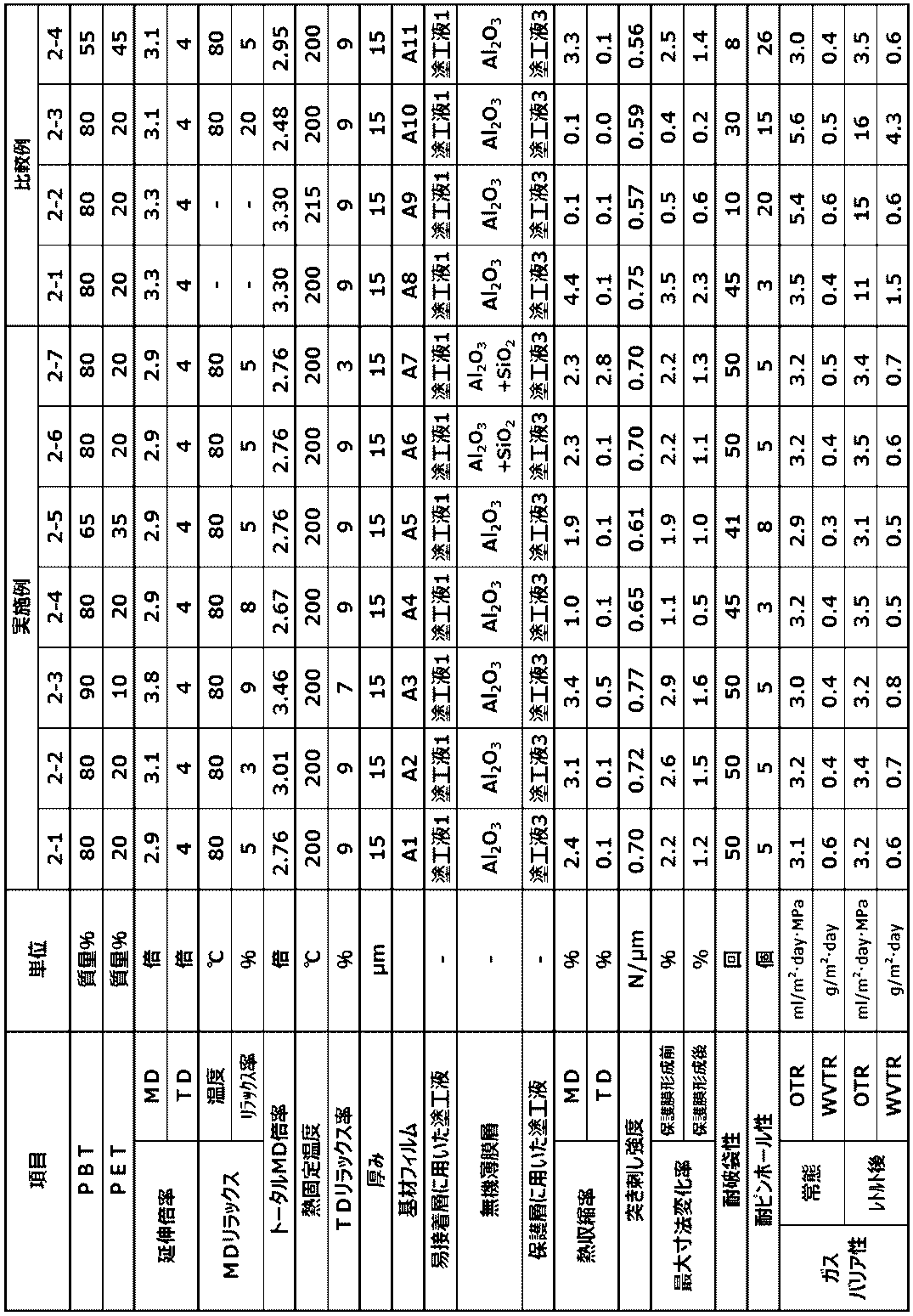
表1及び表2に示すように、本発明によって得られたガスバリア性積層フィルムは、実施例1-1~1-7及び実施例2-1~2-7にみられるように、最大寸法変化率を所定の範囲内とすることで、保護膜形成によって無機薄膜層がダメージを受けることなく、良好なガスバリア性を発現できるとともに、レトルト処理後においても、加熱~冷却過程での寸法変化が少ないため、ガスバリア層の受けるダメージが軽減され、良好なガスバリア性を維持できていることが確認できる。さらには耐破袋性、耐屈曲ピンホール性に優れていることから、レトルト包装材料として好適に用いることができる。
一方、比較例1-1及び2-1においては、最大寸法変化率、熱収縮率が大きいため、レトルト処理後のガスバリア性が悪かった。
比較例1-2及び2-2においては、従来行われてきたような横延伸後の熱処理温度でのみ、熱収縮率を低減した結果、突き刺し強度や耐破袋性が悪かった。
比較例1-3及び2-3においてはMD方向のリラックス率が高過ぎて、最大寸法変化率、熱収縮率が小さくなりすぎた結果、保護膜形成時に無機薄膜層がダメージを受け、常態でのガスバリア性が悪かった。
比較例1-4及び2-4においては、PBTの比率が少ないために、ガスバリア性が良好であっても、突き刺し強度や耐破袋性が悪かった。
比較例1-2及び2-2においては、従来行われてきたような横延伸後の熱処理温度でのみ、熱収縮率を低減した結果、突き刺し強度や耐破袋性が悪かった。
比較例1-3及び2-3においてはMD方向のリラックス率が高過ぎて、最大寸法変化率、熱収縮率が小さくなりすぎた結果、保護膜形成時に無機薄膜層がダメージを受け、常態でのガスバリア性が悪かった。
比較例1-4及び2-4においては、PBTの比率が少ないために、ガスバリア性が良好であっても、突き刺し強度や耐破袋性が悪かった。
本発明によれば、ガスバリア性、寸法安定性、加工性、耐屈曲性、耐破袋性に優れ、かつ、レトルト殺菌のような過酷な湿熱処理後が施される用途においても、優れたガスバリア性を有するガスバリア性積層フィルム及びこれを用いたラミネート積層体を得ることができる。
本発明により、常態においては勿論のこと湿熱処理を施した後にも、ガスバリア性に優れ、さらには耐破袋性、耐屈曲性を有したガスバリア性積層フィルム及びこれを用いたラミネート積層体を提供することができた。かかるガスバリア性積層フィルムは、製造が容易で経済性や生産安定性に優れ、均質な特性が得られやすいという利点を有している、従って、かかるガスバリア性積層フィルムは、食品包装材料として広く適用でき得ることから、産業界に大きく寄与することが期待される。また、医薬品や工業製品等の包装用途、太陽電池、電子ペーパー、有機EL素子、半導体素子等の工業用途にも広く用いることができる。
本発明により、常態においては勿論のこと湿熱処理を施した後にも、ガスバリア性に優れ、さらには耐破袋性、耐屈曲性を有したガスバリア性積層フィルム及びこれを用いたラミネート積層体を提供することができた。かかるガスバリア性積層フィルムは、製造が容易で経済性や生産安定性に優れ、均質な特性が得られやすいという利点を有している、従って、かかるガスバリア性積層フィルムは、食品包装材料として広く適用でき得ることから、産業界に大きく寄与することが期待される。また、医薬品や工業製品等の包装用途、太陽電池、電子ペーパー、有機EL素子、半導体素子等の工業用途にも広く用いることができる。
Claims (13)
- 少なくとも基材層/無機薄膜層/保護層から構成される積層フィルムであって、下記(a)~(d)の条件を満足することを特徴とするガスバリア性積層フィルム。
(a)基材層がポリブチレンテレフタレート樹脂を60質量%以上含む樹脂組成物からなる。
(b)突き刺し強度が0.6N/μm以上。
(c)150℃でのMD方向の熱収縮率が1~4%、TD方向の熱収縮率が-1~3%。
(d)サーマルメカニカルアナライザーを用いて、初期荷重0.2g昇温速度10℃/分で25℃から160℃まで昇温した後、降温速度-10℃/分で50℃まで降温することで得られるMD方向の寸法変曲線において、昇温過程におけるフィルム原長に対する寸法変化率の最大値Amax(%)、降温過程におけるフィルム原長に対する寸法変化率の最小値Amin(%)としたとき、最大寸法変化率(Amax-Amin)が2%以下である。 - 前記基材層と無機薄膜層の間に易接着層を有することを特徴とする請求項1に記載のガスバリア性積層フィルム。
- 前記無機薄膜層が酸化アルミニウム又は酸化ケイ素と酸化アルミニウムの複合酸化物からなる層であることを特徴とする請求項1又は2に記載のガスバリア性積層フィルム。
- 前記易接着層がオキサゾリン基を有する樹脂を含有する樹脂組成物からなることを特徴とする請求項2又は3に記載のガスバリア性積層フィルム
- 前記保護層が、芳香族または芳香脂肪族成分を含有するウレタン樹脂であることを特徴とする請求項1~5のいずれかに記載のガスバリア性積層フィルム。
- 前記保護層が、少なくとも水溶性高分子と金属アルコキシド及びその加水分解物からなることを特徴とする請求項1~5ののいずれかに記載のガスバリア性積層フィルム。
- 下記(e)の条件を満たす基材層/無機薄膜層から構成されるガスバリア性積層フィルムに保護層を形成することを特徴とする請求項1~5のいずれかに記載のガスバリア性積層フィルムの製造方法。
(e)保護膜形成前のガスバリア性積層フィルムをサーマルメカニカルアナライザーを用いて、初期荷重0.2g昇温速度10℃/分で25℃から160℃まで昇温した後、降温速度-10℃/分で50℃まで降温することで得られる寸法変曲線昇温過程におけるフィルム原長に対する寸法変化率の最大値Amax(%)、降温過程におけるフィルム原長に対する寸法変化率の最小値Amin(%)としたとき、MD方向の最大寸法変化率(Amax-Amin)が0.5~3%以下である。 - 少なくとも請求項1~5のいずれかに記載のガスバリア性積層フィルムとシーラント層からなる120℃で30分間のレトルト処理後の酸素透過度が15ml/m2・day・MPa以下、水蒸気透過度が2g/m2・day以下であるラミネート積層体。
- ガスバリア性積層フィルムの基材層側の面に二軸延伸ポリエチレンテレフタレートフィルムが積層された請求項6に記載のラミネート積層体。
- 請求項7又は8に記載のラミネート積層体からなる包装袋。
- レトルト用に使用されることを特徴とする請求項9記載の包装袋。
- 電子レンジ加熱用に使用されることを特徴とする請求項9記載の包装袋。
- 真空包装用に使用されることを特徴とする請求項9記載の包装袋。
Priority Applications (1)
| Application Number | Priority Date | Filing Date | Title |
|---|---|---|---|
| JP2019570585A JP6927336B2 (ja) | 2018-08-08 | 2019-07-25 | ガスバリア性積層フィルムおよびその製造方法 |
Applications Claiming Priority (4)
| Application Number | Priority Date | Filing Date | Title |
|---|---|---|---|
| JP2018-149440 | 2018-08-08 | ||
| JP2018149440 | 2018-08-08 | ||
| JP2018-153150 | 2018-08-16 | ||
| JP2018153150 | 2018-08-16 |
Publications (1)
| Publication Number | Publication Date |
|---|---|
| WO2020031712A1 true WO2020031712A1 (ja) | 2020-02-13 |
Family
ID=69414069
Family Applications (1)
| Application Number | Title | Priority Date | Filing Date |
|---|---|---|---|
| PCT/JP2019/029160 Ceased WO2020031712A1 (ja) | 2018-08-08 | 2019-07-25 | ガスバリア性積層フィルムおよびその製造方法 |
Country Status (3)
| Country | Link |
|---|---|
| JP (1) | JP6927336B2 (ja) |
| TW (1) | TW202012191A (ja) |
| WO (1) | WO2020031712A1 (ja) |
Cited By (5)
| Publication number | Priority date | Publication date | Assignee | Title |
|---|---|---|---|---|
| KR102326010B1 (ko) * | 2021-01-13 | 2021-11-11 | 코오롱인더스트리 주식회사 | 수분 및 산소 배리어성 적층체 |
| WO2022075425A1 (ja) * | 2020-10-08 | 2022-04-14 | 凸版印刷株式会社 | 積層フィルム |
| WO2023054102A1 (ja) * | 2021-09-30 | 2023-04-06 | 東洋紡株式会社 | 積層フィルム、積層体及び包装体 |
| JP2023086487A (ja) * | 2021-12-10 | 2023-06-22 | 凸版印刷株式会社 | ガスバリア性フィルム、積層体、および包装材料 |
| CN118510706A (zh) * | 2022-01-07 | 2024-08-16 | 凸版控股株式会社 | 树脂膜、层叠体以及包装体 |
Families Citing this family (1)
| Publication number | Priority date | Publication date | Assignee | Title |
|---|---|---|---|---|
| TWI737286B (zh) * | 2020-05-04 | 2021-08-21 | 國立臺北科技大學 | 氣體阻障層合體 |
Citations (9)
| Publication number | Priority date | Publication date | Assignee | Title |
|---|---|---|---|---|
| JP5240387B1 (ja) * | 2012-07-26 | 2013-07-17 | 東洋紡株式会社 | 熱収縮性ポリエステル系フィルムおよび包装体 |
| WO2015072163A1 (ja) * | 2013-11-13 | 2015-05-21 | 東洋紡株式会社 | 二軸延伸ポリエステルフィルムおよびその製造方法 |
| WO2017126563A1 (ja) * | 2016-01-22 | 2017-07-27 | 東洋紡株式会社 | 二軸延伸ポリエステルフィルム、積層体及び包装用袋 |
| JP2018020844A (ja) * | 2017-07-26 | 2018-02-08 | 東洋紡株式会社 | ポリブチレンテレフタレートフィルムを用いた包装袋 |
| WO2018159157A1 (ja) * | 2017-02-28 | 2018-09-07 | 東洋紡株式会社 | 積層フィルム |
| WO2018225559A1 (ja) * | 2017-06-06 | 2018-12-13 | 東洋紡株式会社 | 二軸配向ポリエステルフィルム |
| WO2018225558A1 (ja) * | 2017-06-06 | 2018-12-13 | 東洋紡株式会社 | 二軸配向ポリエステルフィルム |
| WO2019142781A1 (ja) * | 2018-01-22 | 2019-07-25 | 東洋紡株式会社 | 二軸配向ポリエステルフィルム |
| JP2019155845A (ja) * | 2018-03-16 | 2019-09-19 | 東洋紡株式会社 | ラミネート積層体 |
Family Cites Families (2)
| Publication number | Priority date | Publication date | Assignee | Title |
|---|---|---|---|---|
| CN109111585A (zh) * | 2012-05-14 | 2019-01-01 | 东洋纺株式会社 | 聚酯薄膜的制造方法 |
| JP6874277B2 (ja) * | 2015-04-24 | 2021-05-19 | 東洋紡株式会社 | 二軸延伸ポリエステルフィルムおよびその製造方法 |
-
2019
- 2019-07-22 TW TW108125820A patent/TW202012191A/zh unknown
- 2019-07-25 WO PCT/JP2019/029160 patent/WO2020031712A1/ja not_active Ceased
- 2019-07-25 JP JP2019570585A patent/JP6927336B2/ja active Active
Patent Citations (9)
| Publication number | Priority date | Publication date | Assignee | Title |
|---|---|---|---|---|
| JP5240387B1 (ja) * | 2012-07-26 | 2013-07-17 | 東洋紡株式会社 | 熱収縮性ポリエステル系フィルムおよび包装体 |
| WO2015072163A1 (ja) * | 2013-11-13 | 2015-05-21 | 東洋紡株式会社 | 二軸延伸ポリエステルフィルムおよびその製造方法 |
| WO2017126563A1 (ja) * | 2016-01-22 | 2017-07-27 | 東洋紡株式会社 | 二軸延伸ポリエステルフィルム、積層体及び包装用袋 |
| WO2018159157A1 (ja) * | 2017-02-28 | 2018-09-07 | 東洋紡株式会社 | 積層フィルム |
| WO2018225559A1 (ja) * | 2017-06-06 | 2018-12-13 | 東洋紡株式会社 | 二軸配向ポリエステルフィルム |
| WO2018225558A1 (ja) * | 2017-06-06 | 2018-12-13 | 東洋紡株式会社 | 二軸配向ポリエステルフィルム |
| JP2018020844A (ja) * | 2017-07-26 | 2018-02-08 | 東洋紡株式会社 | ポリブチレンテレフタレートフィルムを用いた包装袋 |
| WO2019142781A1 (ja) * | 2018-01-22 | 2019-07-25 | 東洋紡株式会社 | 二軸配向ポリエステルフィルム |
| JP2019155845A (ja) * | 2018-03-16 | 2019-09-19 | 東洋紡株式会社 | ラミネート積層体 |
Cited By (11)
| Publication number | Priority date | Publication date | Assignee | Title |
|---|---|---|---|---|
| WO2022075425A1 (ja) * | 2020-10-08 | 2022-04-14 | 凸版印刷株式会社 | 積層フィルム |
| KR102326010B1 (ko) * | 2021-01-13 | 2021-11-11 | 코오롱인더스트리 주식회사 | 수분 및 산소 배리어성 적층체 |
| WO2022154305A1 (ko) * | 2021-01-13 | 2022-07-21 | 코오롱인더스트리 주식회사 | 수분 및 산소 배리어성 적층체 |
| US12447724B2 (en) | 2021-01-13 | 2025-10-21 | Kolon Industries, Inc. | Moisture and oxygen barrier laminate |
| WO2023054102A1 (ja) * | 2021-09-30 | 2023-04-06 | 東洋紡株式会社 | 積層フィルム、積層体及び包装体 |
| JP2023050910A (ja) * | 2021-09-30 | 2023-04-11 | 東洋紡株式会社 | 積層フィルム、積層体及び包装体 |
| JP7279759B2 (ja) | 2021-09-30 | 2023-05-23 | 東洋紡株式会社 | 積層フィルム、積層体及び包装体 |
| JP2023103333A (ja) * | 2021-09-30 | 2023-07-26 | 東洋紡株式会社 | 積層フィルム、積層体及び包装体 |
| JP7468747B2 (ja) | 2021-09-30 | 2024-04-16 | 東洋紡株式会社 | 積層フィルム、積層体及び包装体 |
| JP2023086487A (ja) * | 2021-12-10 | 2023-06-22 | 凸版印刷株式会社 | ガスバリア性フィルム、積層体、および包装材料 |
| CN118510706A (zh) * | 2022-01-07 | 2024-08-16 | 凸版控股株式会社 | 树脂膜、层叠体以及包装体 |
Also Published As
| Publication number | Publication date |
|---|---|
| JPWO2020031712A1 (ja) | 2020-08-20 |
| TW202012191A (zh) | 2020-04-01 |
| JP6927336B2 (ja) | 2021-08-25 |
Similar Documents
| Publication | Publication Date | Title |
|---|---|---|
| JP6927336B2 (ja) | ガスバリア性積層フィルムおよびその製造方法 | |
| JP6962364B2 (ja) | 積層フィルム | |
| CN108472860A (zh) | 双轴拉伸聚酯薄膜、层叠体和包装用袋 | |
| JPWO2020080131A1 (ja) | 積層フィルム | |
| JP6819816B2 (ja) | ポリエステルフィルムロール | |
| JPWO2018225559A1 (ja) | 二軸配向ポリエステルフィルム | |
| WO2020203106A1 (ja) | ポリエステルフィルム及びその製造方法 | |
| JP7060842B2 (ja) | ラミネート積層体 | |
| JP7006445B2 (ja) | ポリエステルフィルムおよびガスバリア性積層フィルム | |
| CN113498376A (zh) | 双轴取向聚酯薄膜和双轴取向聚酯薄膜的制造方法 | |
| JP6879473B2 (ja) | 二軸配向ポリエステルフィルム | |
| WO2018179726A1 (ja) | 二軸配向ポリエステルフィルム及びその製造方法 | |
| JP7574646B2 (ja) | 積層フィルム | |
| JPWO2019142781A1 (ja) | 二軸配向ポリエステルフィルム | |
| JP7279759B2 (ja) | 積層フィルム、積層体及び包装体 | |
| JP7310876B2 (ja) | ポリエステルフィルムおよびガスバリア性積層フィルム | |
| JP2019171587A (ja) | ポリエステルフィルムおよびガスバリア性積層フィルム | |
| JP7365568B2 (ja) | 二軸配向ポリエステルフィルム、及び、二軸配向ポリエステルフィルムの製造方法 |
Legal Events
| Date | Code | Title | Description |
|---|---|---|---|
| ENP | Entry into the national phase |
Ref document number: 2019570585 Country of ref document: JP Kind code of ref document: A |
|
| 121 | Ep: the epo has been informed by wipo that ep was designated in this application |
Ref document number: 19847589 Country of ref document: EP Kind code of ref document: A1 |
|
| NENP | Non-entry into the national phase |
Ref country code: DE |
|
| 122 | Ep: pct application non-entry in european phase |
Ref document number: 19847589 Country of ref document: EP Kind code of ref document: A1 |