WO2020031658A1 - 通信ネットワーク - Google Patents
通信ネットワーク Download PDFInfo
- Publication number
- WO2020031658A1 WO2020031658A1 PCT/JP2019/028446 JP2019028446W WO2020031658A1 WO 2020031658 A1 WO2020031658 A1 WO 2020031658A1 JP 2019028446 W JP2019028446 W JP 2019028446W WO 2020031658 A1 WO2020031658 A1 WO 2020031658A1
- Authority
- WO
- WIPO (PCT)
- Prior art keywords
- vlan
- communication
- monitored person
- type
- data
- Prior art date
- Legal status (The legal status is an assumption and is not a legal conclusion. Google has not performed a legal analysis and makes no representation as to the accuracy of the status listed.)
- Ceased
Links
Images


Classifications
-
- H—ELECTRICITY
- H04—ELECTRIC COMMUNICATION TECHNIQUE
- H04L—TRANSMISSION OF DIGITAL INFORMATION, e.g. TELEGRAPHIC COMMUNICATION
- H04L12/00—Data switching networks
- H04L12/28—Data switching networks characterised by path configuration, e.g. LAN [Local Area Networks] or WAN [Wide Area Networks]
- H04L12/46—Interconnection of networks
-
- H—ELECTRICITY
- H04—ELECTRIC COMMUNICATION TECHNIQUE
- H04M—TELEPHONIC COMMUNICATION
- H04M9/00—Arrangements for interconnection not involving centralised switching
Definitions
- the present invention relates to a communication network used for communication of a monitored person monitoring support system.
- a predetermined event for example, a fall
- a monitored person for example, a care recipient living in a nursing facility
- the predetermined event is generated.
- a monitored person monitoring support technology that notifies a monitored person (for example, a caregiver) when the monitoring is performed.
- the monitor rushes to the monitored person and responds to the event that has occurred.
- the monitoring person monitoring support technology the monitoring person does not need to constantly watch the monitored person, so that the burden on the monitoring person can be reduced and the shortage of the monitoring person can be dealt with.
- Patent Document 1 discloses a nurse call system as a monitored person monitoring support technology. According to the nurse call system, not only communication with the nurse call slave unit and the nurse call master unit of the group to which the mobile terminal belongs, but also communication with the nurse call slave unit and the nurse call master unit of the other groups. It can be implemented with simple operations.
- VLAN Virtual Local Area Network
- VLANs share a physical network. For this reason, when the VLAN allocated to the communication of the monitored person monitoring support system and the VLAN allocated to another system different from this system are set, another system is set by the communication of the monitored person monitoring supporting system. Communication may cause an unexpected trouble, or communication of another system may cause an unexpected trouble in the communication of the monitored person monitoring support system.
- An object of the present invention is to provide a communication network capable of appropriately operating a VLAN allocated to communication of a monitored person monitoring support system and a VLAN allocated to a system different from the VLAN. .
- a communication network is assigned to each of a plurality of monitored persons, and detects that a predetermined event has occurred for the assigned monitored persons.
- the communication control device in the first VLAN and the second VLAN, it is possible to set the one of to prioritize communication than the other.
- FIG. 1 is an explanatory diagram illustrating a configuration of a communication system according to an embodiment.
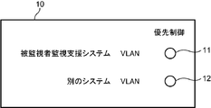
- FIG. 9 is an explanatory diagram illustrating an example of a setting screen for priority control. It is a functional block diagram of an L2 switch.
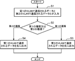
- 11 is a flowchart illustrating an operation of an L2 switch when priority control is set for communication of a second VLAN.
- the monitored person monitoring support system is a system that monitors a monitored person to be monitored (in other words, a watching target to be watched) using a plurality of devices.
- a monitoring target monitoring device that is communicably connected to the terminal device, detects a predetermined event (event) relating to the monitoring target, and notifies the terminal device of the event.
- the monitored person monitoring support device may be integrally formed by one device, in the present specification, the monitored person monitoring supporting device can communicate with a sensor device, and each of the sensor device and the terminal device. And a management server device connected to the device, the two types of devices are configured separately.
- the sensor device detects the predetermined event relating to the monitored person and notifies (notifies and transmits) the management server device.
- the management server device Upon receiving the notification from the sensor device, the management server device manages the notified event and re-notifies the event to a predetermined terminal device associated with the sensor device (re-notification, re-notification, Send.
- the terminal device may be one type of device, but in the present specification, the terminal device is two types of devices, a fixed terminal device and a portable terminal device.
- the main difference between the fixed terminal device and the portable terminal device is that the fixed terminal device is fixedly operated and the portable terminal device is operated by being carried by a monitor (user) such as a nurse or a caregiver. It is. Since the fixed terminal device and the portable terminal device are substantially the same, the portable terminal device will be mainly described below.
- FIG. 1 is an explanatory diagram illustrating the configuration of the communication system according to the embodiment.
- This communication system includes an L2 switch LS, a first VLAN, and a second VLAN, and is used for communication of a monitored person monitoring support system MS and communication of a system AS different from this system. Is done.
- the monitored person monitoring support system MS includes one or a plurality of sensor devices SU (SU-1 to SU-4), a management server device SV, a fixed terminal device SP, and one or a plurality of mobile terminal devices TA (TA-TA). 1, TA-2) and a private branch exchange (PBX, Private Branch eXchange) CX, which communicate via a network (network, communication line) NW such as a LAN (Local Area Network) by wire or wireless. Connected as possible.
- the network NW may be provided with a repeater such as a repeater, a bridge, and a router that relays a communication signal.
- a repeater such as a repeater, a bridge, and a router that relays a communication signal.
- the plurality of sensor devices SU-1 to SU-4, the management server device SV, the fixed terminal device SP, the plurality of portable terminal devices TA-1, TA-2, and the private branch exchange CX are L2 switches. They are communicably connected to each other by a wired and wireless LAN (for example, a LAN according to the IEEE 802.11 standard) NW including the LS and the access point AP. More specifically, the plurality of sensor devices SU-1 to SU-4, the management server device SV, the fixed terminal device SP, and the private branch exchange CX are connected to the L2 switch LS, and the plurality of mobile terminal devices TA-1, TA-2. Is connected to the L2 switch LS via the access point AP.
- the network NW forms a so-called intranet by using an Internet protocol group such as TCP (Transmission Control Protocol) and IP (Internet Protocol).
- the private branch exchange CX is connected to the telephone TL by a public telephone network PN.
- the monitored person monitoring support system MS is provided at an appropriate place according to the monitored person Ob.
- the monitored person Ob is, for example, a person who needs nursing due to illness or injury, a person who needs care due to a decrease in physical ability, or a single person living alone.
- the monitored person Ob may be a person who needs to be detected when a predetermined inconvenient event such as an abnormal state occurs in the person. preferable.
- the monitored person monitoring support system MS is suitably installed in buildings such as hospitals, welfare facilities for the elderly, and dwelling units according to the type of the monitored person Ob.
- the monitored person monitoring support system MS is disposed in a building of a nursing facility including a plurality of rooms RM in which a plurality of monitored persons Ob enter, and a plurality of rooms such as nurse stations. .
- the sensor device SU has a communication function for communicating with the other devices SV, SP, and TA via the network NW, detects a predetermined event relating to the monitored person Ob, and transmits the detected event to the management server device SV.
- a voice call is made with the terminal devices SP and TA, and an image including a moving image is generated to distribute the moving image to the terminal devices SP and TA.
- the predetermined event preferably includes an event that needs to be dealt with.
- an event detection method there is a method using a moving image.
- the sensor device SU captures a moving image of the monitored person Ob, and detects that a predetermined event (for example, getting up, leaving the bed, or falling) has occurred in the monitored person Ob based on the moving image. More specifically, the sensor device SU detects the person area of the monitored person Ob from each frame of the moving image of the monitored person Ob, and determines the posture of the monitored person Ob (for example, standing position) from the aspect ratio of the detected person area. , Sitting position, lying down, etc.), the detected position of the person region is detected, and based on these determinations and the detected posture and position of the monitored person Ob, it is determined whether to wake up, get out of bed, or fall.
- a predetermined event for example, getting up, leaving the bed, or falling
- FIG. 1 shows, as an example, four sensor devices SU-1 to SU-4.
- the sensor device SU-1 is a living room RM- of Mr. A Ob-1 which is one of the monitored persons Ob. 1
- the sensor device SU-2 is disposed in the room RM-2 of Mr. B Ob-2, who is one of the monitored persons Ob
- the sensor device SU-3 is disposed in one of the monitored persons Ob.
- the sensor device SU-4 is arranged in a room RM-3 of a certain person Ob, who is one of the monitored persons Ob-4.
- the management server device SV has a communication function for communicating with other devices SU, SP, and TA via the network NW, and receives a notification of a predetermined event related to the monitored person Ob from the sensor device SU.
- This device manages information (monitoring information) related to monitoring of Ob.
- the management server device SV When receiving the first event notification communication signal as the notification of the event from the sensor device SU, the management server device SV performs the monitoring related to the monitoring of the monitored person Ob on the basis of each information contained in the first event notification communication signal.
- a communication terminal (a second event notification communication signal) containing the monitoring information relating to monitoring of the monitored person Ob is stored (recorded) in a predetermined terminal device previously associated with the sensor device SU. Send to SP, TA.
- the management server SV transmits the sensor ID, which is the transmission source, indicating the notification destination (re-notification destination, re-notification destination, transmission destination) of the first event notification communication signal or the like transmitted from the sensor device SU.
- the correspondence relationship with the terminal ID that is the destination (re-notification destination) (notification destination correspondence relationship) and the communication address thereof are stored.
- the terminal ID (terminal device identifier) is an identifier for specifying and identifying the terminal devices SP and TA.
- the management server SV provides the client with data corresponding to a request of the client (in this embodiment, the fixed terminal SP, the portable terminal TA, and the like).
- Such a management server device SV can be configured by, for example, a computer with a communication function.
- the fixed terminal device SP is a device that functions as a user interface (UI) of the monitored person monitoring support system MS. To achieve this function, the fixed terminal device SP transmits a communication function for communicating with other devices SU, SV, and TA via the network NW, a display function for displaying predetermined information, and a predetermined instruction and data. It has an input function and the like for inputting, and inputs predetermined instructions and data given to the management server device SV and the mobile terminal device TA, and displays monitoring information obtained by the sensor device SU.
- a fixed terminal device SP can be constituted by, for example, a computer having a communication function.
- the portable terminal device TA is carried by the observer NS.
- the mobile terminal device TA has a communication function of communicating with other devices SV, SP, and SU via the network NW, a display function of displaying predetermined information, an input function of inputting predetermined instructions and data, and a voice call. It has a communication function to perform, for example, inputs predetermined instructions and data to be given to the management server device SV and the sensor device SU, and receives monitoring information (including moving images) obtained by the sensor device SU by a notification from the management server device SV. It is a device for displaying, responding to or calling out a nurse call by voice communication with the sensor device SU.
- Another system AS is, for example, a system for making a reservation for a tour of a nursing facility in which the monitored person monitoring support system MS has been introduced, and a system of an accounting unit of the nursing facility.
- Another system AS includes a server SV1 used for this system and one or more personal computers PC1 accessible to the server SV1. These are connected to the L2 switch LS.
- the administrator's personal computer PC2 is a personal computer used by an administrator who manages the monitored person monitoring support system MS and another system AS.
- the administrator personal computer PC2 is connected to the L2 switch LS.
- the L2 switch LS is an example of a communication control device capable of setting a VLAN.
- the administrator's personal computer PC2 is used for setting the VLAN.
- the first VLAN and the second VLAN are set in the network NW which is a physical network by the L2 switch LS.
- the first VLAN is a VLAN assigned to communication of the monitored person monitoring support system MS.
- the sensor device SU, the management server device SV, the fixed terminal device SP, the private branch exchange CX, and the access point AP are virtually connected by the first VLAN.
- the second VLAN is a VLAN assigned to communication of another system AS.
- the personal computer PC1, the server SV1, and the private branch exchange CX are virtually connected by the second VLAN.
- the L2 switch LS is used as a communication control device capable of setting a VLAN, but an L3 switch may be used as a communication control unit.
- the number of the different system AS is one, but the number of the different system AS may be plural. In this case, a VLAN is set for each of these systems.
- the communication network of the new system is established by using a physical network used for the communication network of the existing system. Can be built. This will be specifically described. It is assumed that a communication network of another system AS is constructed, and a communication network of the monitored person monitoring support system MS is newly constructed. A physical network including the L2 switch LS, the private branch exchange CX, and the like already exists. By connecting devices (sensor device SU, management server device SV, fixed terminal device SP, access point AP) used for communication of the monitored person monitoring support system MS to the L2 switch LS, the monitored person monitoring supporting system An MS communication network can be constructed.
- the L2 switch LS can be set so that one of the first VLAN and the second VLAN gives priority to communication over the other. explain in detail. This can be achieved by, for example, QoS (Quality of Service) priority control.
- the administrator's personal computer PC2 is used for setting the priority control.
- FIG. 2 is an explanatory diagram illustrating an example of the setting screen 10 for priority control.
- the setting screen 10 is displayed on the display of the administrator personal computer PC2, and includes radio buttons 11 and 12.
- the radio button 11 corresponds to the VLAN (first VLAN) assigned to the communication of the monitored person monitoring support system MS.
- the administrator operates the administrator's personal computer PC2 and checks the radio button 11.
- a setting is made in the L2 switch LS to prioritize the communication of the first VLAN.
- the communication of the first VLAN is given priority over the communication of the second VLAN, so that the communication of the monitored person monitoring support system MS can be given priority over the communication of another system AS. If immediacy is not required for communication of another system AS, a setting is made to give priority control to communication of the first VLAN.
- the radio button 12 corresponds to a VLAN (second VLAN) assigned to communication of another system AS.
- the administrator operates the administrator personal computer PC2 and checks the radio button 12.
- the L2 switch LS is set to give priority to the communication of the second VLAN.
- the communication of the second VLAN is given priority over the communication of the first VLAN, so that the communication of another system AS can be given priority over the communication of the monitored person monitoring support system MS.
- a setting is made to give priority control to communication of the second VLAN.
- the priority control is not set to the L2 switch LS.
- FIG. 3 is a functional block diagram of the L2 switch LS.
- the L2 switch LS includes a plurality of ports 20, a queue 21, a MAC address table 22, and a switch control unit 23.
- the port 20 is an input / output terminal that can be connected to a device external to the L2 switch LS.
- the queue 21, the MAC address table 22, and the switch control unit 23 include, for example, a hardware processor such as a CPU (Central Processing Unit), a RAM (Random Access Memory), a ROM (Read Only Memory), and a HDD (Hard Disk Drive). , And a program for executing these functions.
- a hardware processor such as a CPU (Central Processing Unit), a RAM (Random Access Memory), a ROM (Read Only Memory), and a HDD (Hard Disk Drive).
- a program for executing these functions Some or all of the functions of the queue 21, the MAC address table 22, and the switch control unit 23 may be realized by processing by a DSP (Digital Signal Processor) instead of or together with processing by the CPU.
- DSP Digital Signal Processor
- some or all of the functions of the queue 21, the MAC address table 22, and the switch control unit 23 may be realized by processing by a dedicated hardware circuit instead of or together with processing by software.
- Network NW Sensor device SU, management server device SV, fixed terminal device SP, private branch exchange CX, access point AP, personal computer PC1, server SV1, administrator personal computer PC2 )
- NW network NW
- management server device SV fixed terminal device SP
- private branch exchange CX private branch exchange CX
- access point AP personal computer PC1, server SV1, administrator personal computer PC2
- the queue 21 temporarily holds data (packets) input / output to / from each port 20.
- the MAC address table 22 stores the numbers of the ports 20 of the plurality of ports 20 in association with the MAC addresses of the devices that communicate using the network NW. Specifically, it is assumed that the number of the port 20 connected to the sensor device SU-1 is 1. The MAC address table 22 stores the MAC address of the sensor device SU-1 and the number 1 in association with each other.
- the switch control unit 23 When data (packet) is input to the port 20, the switch control unit 23 refers to the MAC address table 22 and specifies a number associated with the destination MAC address included in the data (packet). , The output of data (packet) from the port 20 of this number.
- a first VLAN and a second VLAN are set in the L2 switch LS.
- the switch control unit 23 determines the devices (the sensor device SU, the management server device SV, the fixed terminal device SP, the private branch exchange CX, and the access point AP) virtually connected by the first VLAN. Control is performed to enable communication between devices, and control is performed to enable communication between these devices (the personal computer PC1, the server SV1, and the private branch exchange CX) virtually connected by the second VLAN. , The communication between the device virtually connected by the first VLAN and the device virtually connected by the second VLAN is controlled.
- the switch control unit 23 When the priority control is not set for the L2 switch LS, the switch control unit 23 performs a FIFO process. That is, the switch control unit 23 controls the data (packet) stored in the queue 21 to output the data (packet) from the port 20 in the order in which the data (packet) is input to the port 20.
- the L2 switch LS When data passing through the first VLAN and data passing through the second VLAN are input to the L2 switch LS in a state where priority control is set in the L2 switch LS, the L2 switch LS has a higher priority. After outputting data (packet), data (packet) with low priority is output. explain in detail.
- the switch control unit 23 sets a queue. After controlling to output the data passing through the first VLAN from the port 20 among the data (packets) stored in the port 21, the control is performed to output the data passing through the second VLAN from the port 20.
- the switch control unit 23 sets the queue After controlling to output the data passing through the second VLAN from the port 20 among the data (packets) stored in the port 21, the control is performed to output the data passing through the first VLAN from the port 20.
- the priority control is not limited to the absolute priority described above, but may be another method (for example, weighted round robin (WRR: Weighted Round Robin)).
- the L2 switch LS communication control device
- communication of another system AS has priority over communication of the monitored person monitoring support system MS. Is done.
- the communication of the monitored person monitoring support system MS may require immediacy (for example, notification of a nurse call or a fall). Therefore, the L2 switch LS gives priority to communication of the first VLAN over communication of the second VLAN under certain conditions, even when priority control is set for communication of the second VLAN. . This will be described.
- the types of data communicated by the first VLAN are divided in advance into a first type and a second type.
- the monitored person monitoring support system MS is assigned to the first VLAN. Therefore, data communicated by the first VLAN is data communicated by the monitored person monitoring support system MS.
- the type of data communicated in the first VLAN is indicated in the header of each packet constituting the data.
- the first type of data is data having such a size that if priority is given to communication of the first VLAN, communication of the second VLAN will be greatly hindered.
- the first type of data is, for example, a moving image of the monitored person Ob captured by the sensor device SU in order to detect that the sensor device SU has generated a predetermined event (for example, a fall) on the monitored person Ob. .
- the sensor device SU transmits the captured moving image to the management server device SV, and the management server device SV stores the moving image.
- the moving image is used when the state of the monitored person Ob is confirmed later (for example, whether or not the monitored person Ob is abused).
- the second type of data is data having a size that does not cause a great hindrance to the communication of the second VLAN even if the communication of the first VLAN is prioritized.
- the second type of data includes, for example, a text indicating the name and room number of the monitored person Ob who made the nurse call, and the name of the monitored person Ob who fell when the sensor device SU detected the falling of the monitored person Ob. And text indicating the room number.
- the former text is sent from a nurse call slave (not shown) to a nurse call master (not shown). Then, the former text is transmitted from the nurse call master device to each portable terminal device TA via the management server device SV using the first VLAN.
- FIG. 4 is a flowchart illustrating the operation of the L2 switch LS when the priority control is set for the communication of the second VLAN.
- data communicated in the first VLAN and data communicated in the second VLAN are input to L2 switch LS (step S1).
- the switch control unit 23 determines whether the type of data communicated by the first VLAN is the first type or the second type (step S2). The type of data is indicated in the packet header.
- the switch control unit 23 controls to output data communicated in the second VLAN first, and Control to output data communicated by VLAN is performed (step S3).
- the switch control unit 23 controls to output the data communicated in the first VLAN first, and Control to output data communicated by VLAN is performed (step S4).
- the communication network according to the embodiment is assigned to each of a plurality of monitored persons, a plurality of sensor devices for detecting that a predetermined event has occurred for the assigned monitored persons, and a plurality of monitored persons carry each of them.
- a possible communication control device, a first VLAN assigned by the communication control device for communication of the monitored person monitoring support system, and the monitored person monitoring support set by the communication control device And a second VLAN assigned to communication between another system and the other system, wherein the communication control device includes the first VLAN and the second VLAN. In a serial second VLAN, the it is possible to set the one of to prioritize communication than the other.
- One means that the communication has priority over the other means that the communication of the first VLAN has priority over the communication of the second VLAN, or the communication of the second VLAN has priority over the communication of the first VLAN. It is. By prioritizing the communication of the first VLAN, the communication of the monitored person monitoring system can be prioritized. By giving priority to the communication of the second VLAN, communication of another system can be given priority.
- the communication control unit can set one of the first VLAN and the second VLAN to give priority to communication over the other.
- the user can set the communication control unit to give priority to one to the communication over the other. Therefore, according to the communication network according to the embodiment, the VLAN allocated to the communication of the monitored person monitoring support system and the VLAN allocated to a system different from this system can be appropriately operated.
- the type of data to be communicated in the first VLAN is predetermined in a state where the communication in the second VLAN is set to have priority over the communication in the first VLAN.
- the communication of the second VLAN is prioritized over the communication of the first VLAN, and the type of data communicated in the first VLAN is smaller in data amount than the first type.
- the communication of the first VLAN is prioritized over the communication of the second VLAN.
- the first type of data is data having such a size that if the communication of the first VLAN is prioritized, the communication of the second VLAN will be greatly hindered (for example, a moving image).
- the second type of data is data having a size (for example, short text) that does not cause a great hindrance to the communication of the second VLAN even if the communication of the first VLAN is prioritized.
- the communication control device When the type of data communicated with the first VLAN is the first type under the setting of giving priority to the communication of the second VLAN over the communication of the first VLAN, the communication control device performs The communication of the second VLAN is prioritized over the communication of the first VLAN.
- the communication control device changes the communication of the first VLAN to the second VLAN as an exception. Give priority over communication. This configuration is effective when the second type of data has immediacy (for example, text indicating the name and room number of the monitored person who made the nurse call).
- each of the plurality of sensor devices captures a moving image of the assigned monitored person, detects that the assigned monitored person has fallen, based on the moving image, and detects a fall.
- a text indicating the detected name and room number of the monitored person is sent to the plurality of terminal devices from the sensor device that has detected a fall via the server device using the first VLAN,
- the moving image captured by each of the plurality of sensor devices is sent to the server device using the first VLAN, and the first type of data is the moving image captured by each of the plurality of sensor devices.
- the second type of data includes text indicating a name and a room number of the monitored person whose fall has been detected.
- the text indicating the name and the room number of the monitored person who has detected the fall is sent from the sensor device that has detected the fall to a plurality of terminal devices via the server device. Thereby, each monitor can know that the monitored person has fallen.
- the moving image captured by each of the plurality of sensor devices is sent to the server device and stored in the server device. These moving images are used when the state of the monitored person is later checked (for example, whether or not the monitored person is abused).
- the text indicating the name and room number of the monitored person whose fall was detected has immediacy.
- a moving image captured by each of the plurality of sensor devices has no immediacy.
- the text is the second type of data
- the moving image is the first type of data. According to this configuration, even in a state in which the communication of the second VLAN is set to have a higher priority than the communication of the first VLAN, the fall is detected without causing a great obstacle to the communication of the second VLAN.
- the communication of the text indicating the name and room number of the monitored person can be prioritized.
- a communication network can be provided.
Landscapes
- Engineering & Computer Science (AREA)
- Signal Processing (AREA)
- Computer Networks & Wireless Communication (AREA)
- Data Exchanges In Wide-Area Networks (AREA)
- Small-Scale Networks (AREA)
- Interconnected Communication Systems, Intercoms, And Interphones (AREA)
- Telephonic Communication Services (AREA)
- Alarm Systems (AREA)
Abstract
通信ネットワークは、VLANの設定が可能な通信制御装置(L2スイッチ)と、通信制御装置によって設定された、被監視者監視支援システムの通信に割り当てられた第1のVLANと、通信制御装置によって設定された、被監視者監視支援システムと別のシステムの通信に割り当てられた第2のVLANと、を備え、通信制御装置は、第1のVLANと第2のVLANとにおいて、一方が他方よりも通信を優先させる設定が可能である。
Description
本発明は、被監視者監視支援システムの通信に使用される通信ネットワークに関する。
近年、超高齢社会の突入に伴って、看護業界、介護業界等の業務を補完する技術の研究、開発が進められている。このような技術の一つとして、被監視者(例えば、介護施設に入居している被介護者)に所定のイベント(例えば、転倒)が発生したか否かを監視し、所定のイベントが発生した場合、監視者(例えば、介護士)に通知する被監視者監視支援技術がある。監視者は、通知を受けたとき、被監視者のもとに駆け付け、発生したイベントに対応する。この被監視者監視支援技術によれば、監視者は、被監視者を常に見守る必要がないので、監視者の負担を軽減できると共に、監視者の人手不足に対応することができる。
例えば、特許文献1は、被監視者監視支援技術として、ナースコールシステムを開示している。このナースコールシステムによれば、携帯端末が所属しているグループのナースコール子機やナースコール親機との通信だけでなく、他のグループのナースコール子機やナースコール親機との通信を簡易な操作で実施できる。
ある施設に被監視者監視支援システムが既に導入された状態で、その施設に別のシステムが新たに導入されることがあり、また、これと逆のことがある。これらのシステムのそれぞれの通信にVLAN(Virtual Local Area Network)が採用されることがある。VLANは、既存の物理ネットワークを利用できるので、導入コストを下げることができる。
VLANは物理ネットワークを共用する。このため、被監視者監視支援システムの通信に割り当てられたVLANと、このシステムとは別のシステムに割り当てられたVLANとが設定されているとき、被監視者監視支援システムの通信によって別のシステムの通信に予期せぬ支障が生じたり、別のシステムの通信によって被監視者監視支援システムの通信に予期せぬ支障が生じたりすることある。
本発明の目的は、被監視者監視支援システムの通信に割り当てられたVLANと、このシステムとは別のシステムに割り当てられたVLANとを適切に運用することができる通信ネットワークを提供することである。
上述した目的を実現するために、本発明の一側面を反映した通信ネットワークは、複数の被監視者のそれぞれに割り当てられ、割り当てられた被監視者について、所定のイベントが発生したことを検知する複数のセンサ装置と、複数の監視者がそれぞれ携行する複数の端末装置と、前記複数のセンサ装置および前記複数の端末装置と通信可能なサーバ装置と、を備える被監視者監視支援システムの通信に使用される通信ネットワークであって、VLANの設定が可能な通信制御装置と、前記通信制御装置によって設定された、前記被監視者監視支援システムの通信に割り当てられた第1のVLANと、前記通信制御装置によって設定された、前記被監視者監視支援システムと別のシステムの通信に割り当てられた第2のVLANと、を備え、前記通信制御装置は、前記第1のVLANと前記第2のVLANとにおいて、一方が他方よりも通信を優先させる設定が可能である。
発明の1又は複数の実施形態により与えられる利点及び特徴は以下に与えられる詳細な説明及び添付図面から十分に理解される。これら詳細な説明及び添付図面は、例としてのみ与えられるものであり本発明の限定の定義として意図されるものではない。
以下、図面を参照して、本発明の1又は複数の実施形態が説明される。しかし、発明の範囲は、開示された実施形態に限定されない。
各図において、同一符号を付した構成は、同一の構成であることを示し、その構成について、既に説明している内容については、その説明を省略する。本明細書において、総称する場合には添え字を省略した参照符号で示し(例えば、センサ装置SU)、個別の構成を指す場合には添え字を付した参照符号で示す(例えば、センサ装置SU-1)。
実施形態に係る被監視者監視支援システムは、監視すべき監視対象である被監視者(言い換えれば、見守るべき見守り対象である見守り対象者)を複数の装置を用いて監視するシステムであり、端末装置と、前記端末装置と通信可能に接続され、被監視者に関わる所定のイベント(事象)を検知して前記イベントを前記端末装置へ通知する被監視者監視支援装置と、を備える。前記被監視者監視支援装置は、1個の装置で一体に構成されて良いが、本明細書では、被監視者監視支援装置は、センサ装置と、前記センサ装置及び前記端末装置それぞれと通信可能に接続される管理サーバ装置とを備えることで、2種類の各装置で別体に構成される。前記センサ装置は、被監視者に関わる前記所定のイベントを検知して前記管理サーバ装置へ通知(報知、送信)する。前記管理サーバ装置は、前記センサ装置から前記通知を受けると、前記通知を受けた前記イベントを管理するとともに前記イベントを前記センサ装置に対応付けられた所定の端末装置へ再通知(再報知、再送信)する。前記端末装置は、1種類の装置であって良いが、本明細書では、前記端末装置は、固定端末装置と携帯端末装置との2種類の装置である。これら固定端末装置と携帯端末装置との主な相違は、固定端末装置が固定的に運用され、携帯端末装置が例えば看護師や介護士等の監視者(ユーザ)に携行されて運用される点である。これら固定端末装置と携帯端末装置とは、略同様であるので、以下では、携帯端末装置を主に説明する。
図1は、実施形態に係る通信システムの構成を説明する説明図である。この通信システムは、L2スイッチLSと、第1のVLANと、第2のVLANと、を備え、被監視者監視支援システムMSの通信、および、このシステムとは別のシステムASの通信にそれぞれ使用される。
被監視者監視支援システムMSは、1または複数のセンサ装置SU(SU-1~SU-4)と、管理サーバ装置SVと、固定端末装置SPと、1または複数の携帯端末装置TA(TA-1、TA-2)と、構内交換機(PBX、Private Branch eXchange)CXとを備え、これらは、有線や無線で、LAN(Local Area Network)等の網(ネットワーク、通信回線)NWを介して通信可能に接続される。ネットワークNWには、通信信号を中継する例えばリピーター、ブリッジ及びルーター等の中継機が備えられても良い。図1に示す例では、これら複数のセンサ装置SU-1~SU-4、管理サーバ装置SV、固定端末装置SP、複数の携帯端末装置TA-1、TA-2及び構内交換機CXは、L2スイッチLS及びアクセスポイントAPを含む有線及び無線の混在したLAN(例えばIEEE802.11規格に従ったLAN等)NWによって互いに通信可能に接続されている。より詳しくは、複数のセンサ装置SU-1~SU-4、管理サーバ装置SV、固定端末装置SP及び構内交換機CXは、L2スイッチLSに接続され、複数の携帯端末装置TA-1、TA-2は、アクセスポイントAPを介してL2スイッチLSに接続されている。そして、ネットワークNWは、TCP(Transimission Control Protocol)及びIP(Internet Protocol)等のインターネットプロトコル群が用いられることによっていわゆるイントラネットを構成する。構内交換機CXは、公衆電話網PNによって電話TLと接続されている。
被監視者監視支援システムMSは、被監視者Obに応じて適宜な場所に配設される。被監視者Obは、例えば、病気や怪我等によって看護を必要とする者や、身体能力の低下等によって介護を必要とする者や、一人暮らしの独居者等である。特に、早期発見と早期対処とを可能にする観点から、被監視者Obは、例えば異常状態等の所定の不都合なイベントがその者に生じた場合にその発見を必要としている者であることが好ましい。このため、被監視者監視支援システムMSは、被監視者Obの種類に応じて、病院、老人福祉施設及び住戸等の建物に好適に配設される。図1に示す例では、被監視者監視支援システムMSは、複数の被監視者Obが入居する複数の居室RMや、ナースステーション等の複数の部屋を備える介護施設の建物に配設されている。
センサ装置SUは、ネットワークNWを介して他の装置SV、SP、TAと通信する通信機能等を備え、被監視者Obに関わる所定のイベントを検知してこの検知した前記イベントを管理サーバ装置SVへ通知し、端末装置SP、TAとの間で音声通話を行い、そして、動画を含む画像を生成して端末装置SP、TAへ動画を配信する装置である。前記所定のイベントは、好ましくは、対処が必要なイベントを含む。
イベントの検知方法の一例として、動画を用いる方法がある。センサ装置SUは、被監視者Obの動画を撮影し、この動画を基にして、被監視者Obに所定のイベント(例えば、起床、離床、転倒)が発生したことを検知する。詳しくは、センサ装置SUは、被監視者Obを撮影した動画の各フレームから被監視者Obの人物領域を検出し、この検出した人物領域の縦横比から被監視者Obの姿勢(例えば立位、座位および横臥等)を判定し、この検出した人物領域の位置を検出し、これら判定、検出した被監視者Obの姿勢および位置に基づいて、起床、離床および転倒の別を判定する。
図1には、一例として、4個のセンサ装置SU-1~SU-4が示されており、センサ装置SU-1は、被監視者Obの一人であるAさんOb-1の居室RM-1に配設され、センサ装置SU-2は、被監視者Obの一人であるBさんOb-2の居室RM-2に配設され、センサ装置SU-3は、被監視者Obの一人であるCさんOb-3の居室RM-3に配設され、そして、センサ装置SU-4は、被監視者Obの一人であるDさんOb-4の居室RM-4に配設されている。
管理サーバ装置SVは、ネットワークNWを介して他の装置SU、SP、TAと通信する通信機能等を備え、センサ装置SUから、被監視者Obに関わる所定のイベントの通知を受信すると被監視者Obに対する監視に関する情報(監視情報)を管理する装置である。管理サーバ装置SVは、センサ装置SUから前記イベントの通知として第1イベント通知通信信号を受信すると、前記第1イベント通知通信信号に収容された各情報に基づいて、被監視者Obに対する監視に関する前記監視情報を記憶(記録)し、そして、被監視者Obに対する監視に関する前記監視情報を収容した通信信号(第2イベント通知通信信号)を、前記センサ装置SUに予め対応付けられた所定の端末装置SP、TAに送信する。このために、管理サーバ装置SVは、センサ装置SUから送信された第1イベント通知通信信号等の通知先(再通知先、再報知先、送信先)を示す、送信元であるセンサIDと通知先(再通知先)である端末IDとの対応関係(通知先対応関係)、及び、その通信アドレスを記憶する。端末ID(端末装置識別子)は、端末装置SP、TAを特定し識別するための識別子である。そして、管理サーバ装置SVは、クライアント(本実施形態では固定端末装置SP及び携帯端末装置TA等)の要求に応じたデータを前記クライアントに提供する。このような管理サーバ装置SVは、例えば、通信機能付きのコンピュータによって構成可能である。
固定端末装置SPは、被監視者監視支援システムMSのユーザインターフェース(UI)として機能する装置である。この機能を達成するために、固定端末装置SPは、ネットワークNWを介して他の装置SU、SV、TAと通信する通信機能、所定の情報を表示する表示機能、及び、所定の指示及びデータを入力する入力機能等を備え、管理サーバ装置SV及び携帯端末装置TAに与える所定の指示及びデータが入力されたり、センサ装置SUで得られた監視情報を表示したりする。このような固定端末装置SPは、例えば、通信機能付きのコンピュータによって構成可能である。
携帯端末装置TAは、監視者NSが携帯している。携帯端末装置TAは、ネットワークNWを介して他の装置SV、SP、SUと通信する通信機能、所定の情報を表示する表示機能、所定の指示やデータを入力する入力機能、及び、音声通話を行う通話機能等を備え、管理サーバ装置SV及びセンサ装置SUに与える所定の指示及びデータを入力したり、管理サーバ装置SVからの通知によってセンサ装置SUで得られた監視情報(動画を含む)を表示したり、センサ装置SUとの間で音声通話によってナースコールの応答や声かけしたり等をするための機器である。
別のシステムASは、例えば、被監視者監視支援システムMSを導入している介護施設の見学を予約するシステム、この介護施設の経理部のシステムである。別のシステムASは、このシステムに用いられるサーバSV1と、サーバSV1にアクセス可能な1又は複数のパソコンPC1と、備える。これらは、L2スイッチLSに接続されている。
管理者用パソコンPC2は、被監視者監視支援システムMSと別のシステムASとを管理する管理者が使用するパソコンである。管理者用パソコンPC2は、L2スイッチLSに接続されている。
L2スイッチLSは、VLANの設定が可能な通信制御装置の例である。VLANの設定には、管理者用パソコンPC2が用いられる。L2スイッチLSによって、物理ネットワークであるネットワークNWに、第1のVLANと第2のVLANとが設定されている。第1のVLANは、被監視者監視支援システムMSの通信に割り当てられたVLANである。第1のVLANによって、センサ装置SUと、管理サーバ装置SVと、固定端末装置SPと、構内交換機CXと、アクセスポイントAPとが仮想的に接続されている。
第2のVLANは、別のシステムASの通信に割り当てられたVLANである。第2のVLANによって、パソコンPC1と、サーバSV1と、構内交換機CXとが仮想的に接続されている。実施形態では、VLANの設定が可能な通信制御装置として、L2スイッチLSを用いるが、通信制御部としてL3スイッチを用いてもよい。また、実施形態では、別のシステムASは1つであるが、別のシステムASが複数でもよい。この場合、これらのシステムにそれぞれ、VLANが設定される。
VLANによれば、既存のシステムの通信ネットワークが構築された状態で新たなシステムの通信ネットワークを構築する場合、既存のシステムの通信ネットワークに用いられる物理ネットワークを用いて、新たなシステムの通信ネットワークを構築することができる。具体的に説明する。別のシステムASの通信ネットワークが構築されており、被監視者監視支援システムMSの通信ネットワークが新たに構築されるとする。L2スイッチLSおよび構内交換機CX等から構成される物理ネットワークが既に存在している。被監視者監視支援システムMSの通信に使用される機器(センサ装置SU、管理サーバ装置SV、固定端末装置SP、アクセスポイントAP)を、L2スイッチLSに接続することにより、被監視者監視支援システムMSの通信ネットワークを構築することができる。
L2スイッチLSは、第1のVLANと第2のVLANとにおいて、一方が他方よりも通信を優先させる設定が可能である。詳しく説明する。これは、例えば、QoS(Quality of Service)の優先制御によって実現することができる。優先制御の設定には、管理者用パソコンPC2が用いられる。図2は、優先制御の設定画面10の例を説明する説明図である。設定画面10は、管理者用パソコンPC2のディスプレイに表示され、ラジオボタン11,12を含む。
ラジオボタン11は、被監視者監視支援システムMSの通信に割り当てられたVLAN(第1のVLAN)に対応している。第1のVLANの通信を優先制御するとき、管理者は、管理者用パソコンPC2を操作して、ラジオボタン11にチェックを入れる。これにより、L2スイッチLSにおいて、第1のVLANの通信を優先制御する設定がされる。この設定により、第1のVLANの通信が第2のVLANの通信よりも優先されるので、被監視者監視支援システムMSの通信が別のシステムASの通信よりも優先させることができる。別のシステムASの通信に即時性が要求されない場合、第1のVLANの通信を優先制御する設定がされる。
ラジオボタン12は、別のシステムASの通信に割り当てられたVLAN(第2のVLAN)に対応している。第2のVLANの通信を優先制御するとき、管理者は、管理者用パソコンPC2を操作して、ラジオボタン12にチェックを入れる。これにより、L2スイッチLSにおいて、第2のVLANの通信を優先制御する設定がされる。この設定により、第2のVLANの通信が第1のVLANの通信よりも優先されるので、別のシステムASの通信が被監視者監視支援システムMSの通信よりも優先させることができる。別のシステムASの通信に即時性が要求される場合、第2のVLANの通信を優先制御する設定がされる。
ラジオボタン11またはラジオボタン12にチェックが入れられていないとき、L2スイッチLSには優先制御の設定がされない。
図3は、L2スイッチLSの機能ブロック図である。L2スイッチLSは、複数のポート20と、キュー21と、MACアドレステーブル22と、スイッチ制御部23と、を備える。
ポート20は、L2スイッチLSの外部の機器と接続可能な入出力端子である。
キュー21、MACアドレステーブル22およびスイッチ制御部23は、例えば、CPU(Central Processing Unit)、RAM(Random Access Memory)、ROM(Read Only Memory)、および、HDD(Hard Disk Drive)等のハードウェアプロセッサ、並びに、これらの機能を実行するためのプログラム等によって実現される。キュー21、MACアドレステーブル22およびスイッチ制御部23の機能の一部又は全部は、CPUによる処理に替えて、又は、これと共に、DSP(Digital Signal Processor)による処理によって実現されてもよい。又、キュー21、MACアドレステーブル22およびスイッチ制御部23の機能の一部又は全部は、ソフトウェアによる処理に替えて、又は、これと共に、専用のハードウェア回路による処理によって実現されてもよい。
複数のポート20のそれぞれと、ネットワークNWを用いて通信する機器(センサ装置SU、管理サーバ装置SV、固定端末装置SP、構内交換機CX、アクセスポイントAP、パソコンPC1、サーバSV1、管理者用パソコンPC2)とは、LANケーブルによって接続されている。
キュー21は、各ポート20に入出力するデータ(パケット)を一時的に保持する。
MACアドレステーブル22は、複数のポート20のそれぞれのポート20の番号と、ネットワークNWを用いて通信する機器のMACアドレスとを対応付けて記憶している。具体的に説明すると、センサ装置SU-1と接続されているポート20の番号が1とする。MACアドレステーブル22は、センサ装置SU-1のMACアドレスと番号1とを対応付けて記憶している。
スイッチ制御部23は、ポート20にデータ(パケット)が入力したとき、MACアドレステーブル22を参照して、そのデータ(パケット)に含まれる送信先のMACアドレスに対応付けられている番号を特定し、この番号のポート20からデータ(パケット)を出力させる制御をする。
L2スイッチLSには、第1のVLANと第2のVLANとが設定されている。このため、スイッチ制御部23は、第1のVLANによって仮想的に接続されている機器(センサ装置SU、管理サーバ装置SV、固定端末装置SP、構内交換機CX、アクセスポイントAP)について、これらの機器どうしの通信を可能とする制御をし、第2のVLANによって仮想的に接続されている機器(パソコンPC1、サーバSV1、構内交換機CX)について、これらの機器どうしの通信を可能とする制御をし、第1のVLANによって仮想的に接続されている機器と、第2のVLANによって仮想的に接続されている機器とは通信できない制御をする。
L2スイッチLSに優先制御の設定がされていないとき、スイッチ制御部23は、FIFO処理をする。すなわち、スイッチ制御部23は、キュー21に記憶されているデータ(パケット)に対して、データ(パケット)がポート20に入力した順番で、データ(パケット)をポート20から出力させる制御をする。
L2スイッチLSに優先制御の設定がされている状態下、第1のVLANを通るデータと第2のVLANを通るデータとが、L2スイッチLSに入力したとき、L2スイッチLSは、優先度が高いデータ(パケット)を出力した後、優先度が低いデータ(パケット)を出力する。詳しく説明する。第1のVLANの通信に優先制御の設定がされている状態下、第1のVLANを通るデータと第2のVLANを通るデータとが、ポート20に入力したとき、スイッチ制御部23は、キュー21に記憶されているデータ(パケット)のうち、第1のVLANを通るデータをポート20から出力させる制御をした後、第2のVLANを通るデータをポート20から出力させる制御をする。第2のVLANの通信に優先制御の設定がされている状態下、第1のVLANを通るデータと第2のVLANを通るデータとが、ポート20に入力したとき、スイッチ制御部23は、キュー21に記憶されているデータ(パケット)のうち、第2のVLANを通るデータをポート20から出力させる制御をした後、第1のVLANを通るデータをポート20から出力させる制御をする。優先制御は、以上説明した絶対優先に限らず、他の方式(例えば、重み付きラウンドロビン(WRR:Weighted Round Robin)でもよい。
上述したように、L2スイッチLS(通信制御装置)において、第2のVLANの通信に優先制御が設定されているとき、別のシステムASの通信が被監視者監視支援システムMSの通信よりも優先される。しかし、被監視者監視支援システムMSの通信にも即時性が必要とされることがある(例えば、ナースコール、転倒の報知)。そこで、L2スイッチLSは、第2のVLANの通信に優先制御が設定されている場合であっても、一定条件の下で、第1のVLANの通信を第2のVLANの通信よりも優先させる。これについて説明する。
第1のVLANで通信されるデータの種類は、第1の種類と第2の種類とに予め分けられている。第1のVLANには被監視者監視支援システムMSが割り当てられている。このため、第1のVLANで通信されるデータは、被監視者監視支援システムMSが通信するデータである。第1のVLANで通信されるデータの種類は、このデータを構成する各パケットのヘッダに示されている。
第1の種類のデータは、第1のVLANの通信を優先させると、第2のVLANの通信に大きな支障が生じる程度のサイズを有するデータである。第1の種類のデータは、例えば、センサ装置SUが被監視者Obに所定のイベント(例えば、転倒)が発生したこと検知するために、センサ装置SUが撮影した被監視者Obの動画である。センサ装置SUは、撮影した動画を管理サーバ装置SVに送信し、管理サーバ装置SVは、動画を保存する。動画は、被監視者Obの状態を後で確認する場合に用いられる(例えば、被監視者Obが虐待されているか否かの確認)。
第2の種類のデータは、第1のVLANの通信を優先させても、第2のVLANの通信に大きな支障が生じない程度のサイズを有するデータである。第2の種類のデータは、例えば、ナースコールをした被監視者Obの氏名および居室番号を示すテキスト、センサ装置SUが被監視者Obの転倒を検知したとき、転倒した被監視者Obの氏名および居室番号を示すテキストである。前者のテキストは、ナースコール子機(不図示)からナースコール親機(不図示)に送られる。そして、前者のテキストは、第1のVLANを用いて、ナースコール親機から管理サーバ装置SVを経由し、各携帯端末装置TAに送られる。
図4は、第2のVLANの通信に優先制御が設定されている場合に、L2スイッチLSの動作を説明するフローチャートである。図1、図3および図4を参照して、L2スイッチLSに、第1のVLANで通信されるデータと第2のVLANで通信されるデータとが入力する(ステップS1)。スイッチ制御部23は、第1のVLANで通信されるデータの種類が第1の種類か第2の種類かを判断する(ステップS2)。データの種類は、パケットヘッダに示されている。
スイッチ制御部23は、第1のVLANで通信されるデータの種類が第1の種類と判断したとき、第2のVLANで通信されるデータを先に出力させる制御をし、そして、第1のVLANで通信されるデータを出力させる制御をする(ステップS3)。
スイッチ制御部23は、第1のVLANで通信されるデータの種類が第2の種類と判断したとき、第1のVLANで通信されるデータを先に出力させる制御をし、そして、第2のVLANで通信されるデータを出力させる制御をする(ステップS4)。
(実施形態の纏め)
実施形態に係る通信ネットワークは、複数の被監視者のそれぞれに割り当てられ、割り当てられた被監視者について、所定のイベントが発生したことを検知する複数のセンサ装置と、複数の監視者がそれぞれ携行する複数の端末装置と、前記複数のセンサ装置および前記複数の端末装置と通信可能なサーバ装置と、を備える被監視者監視支援システムの通信に使用される通信ネットワークであって、VLANの設定が可能な通信制御装置と、前記通信制御装置によって設定された、前記被監視者監視支援システムの通信に割り当てられた第1のVLANと、前記通信制御装置によって設定された、前記被監視者監視支援システムと別のシステムの通信に割り当てられた第2のVLANと、を備え、前記通信制御装置は、前記第1のVLANと前記第2のVLANとにおいて、一方が他方よりも通信を優先させる設定が可能である。
実施形態に係る通信ネットワークは、複数の被監視者のそれぞれに割り当てられ、割り当てられた被監視者について、所定のイベントが発生したことを検知する複数のセンサ装置と、複数の監視者がそれぞれ携行する複数の端末装置と、前記複数のセンサ装置および前記複数の端末装置と通信可能なサーバ装置と、を備える被監視者監視支援システムの通信に使用される通信ネットワークであって、VLANの設定が可能な通信制御装置と、前記通信制御装置によって設定された、前記被監視者監視支援システムの通信に割り当てられた第1のVLANと、前記通信制御装置によって設定された、前記被監視者監視支援システムと別のシステムの通信に割り当てられた第2のVLANと、を備え、前記通信制御装置は、前記第1のVLANと前記第2のVLANとにおいて、一方が他方よりも通信を優先させる設定が可能である。
一方が他方よりも通信を優先させるとは、第1のVLANの通信を第2のVLANの通信よりも優先させ、または、第2のVLANの通信を第1のVLANの通信よりも優先させることである。第1のVLANの通信を優先させることにより、被監視者監視システムの通信を優先させることができる。第2のVLANの通信を優先させることにより、別のシステムの通信を優先させることができる。
通信制御部は、第1のVLANと第2のVLANとにおいて、一方が他方よりも通信を優先させる設定が可能である。ユーザは、通信の即時性、データ量等を考慮し、一方を他方よりも通信を優先させることを、通信制御部に設定することができる。従って、実施形態に係る通信ネットワークによれば、被監視者監視支援システムの通信に割り当てられたVLANと、このシステムとは別のシステムに割り当てられたVLANとを適切に運用することができる。
上記構成において、前記通信制御装置は、前記第2のVLANの通信を前記第1のVLANの通信よりも優先させる設定の状態で、前記第1のVLANで通信されるデータの種類が予め定められた第1の種類のとき、前記第2のVLANの通信を前記第1のVLANの通信よりも優先させ、前記第1のVLANで通信されるデータの種類が前記第1の種類よりもデータ量が少ない予め定められた第2の種類のとき、前記第1のVLANの通信を前記第2のVLANの通信よりも優先させる。
第1の種類のデータは、第1のVLANの通信を優先させると、第2のVLANの通信に大きな支障が生じる程度のサイズを有するデータである(例えば、動画)。第2の種類のデータは、第1のVLANの通信を優先させても、第2のVLANの通信に大きな支障が生じない程度のサイズを有するデータである(例えば、短いテキスト)。
通信制御装置は、第2のVLANの通信を第1のVLANの通信よりも優先させる設定の状態下、第1のVLANで通信されるデータの種類が第1の種類のとき、原則どおり、第2のVLANの通信を第1のVLANの通信よりも優先させる。これに対して、通信制御装置は、上記設定の状態下、第1のVLANで通信されるデータの種類が第2の種類のとき、例外として、第1のVLANの通信を第2のVLANの通信よりも優先させる。この構成は、第2の種類のデータが、即時性を有する場合に有効である(例えば、ナースコールをした被監視者の氏名および居室番号を示すテキスト)。
上記構成において、前記複数のセンサ装置は、それぞれ、割り当てられた前記被監視者の動画を撮影し、前記動画を基にして、割り当てられた前記被監視者が転倒したことを検知し、転倒を検知された前記被監視者の氏名および居室番号を示すテキストは、前記第1のVLANを用いて、転倒を検知した前記センサ装置から前記サーバ装置を経由して前記複数の端末装置に送られ、前記複数のセンサ装置がそれぞれ撮影した前記動画は、前記第1のVLANを用いて、前記サーバ装置に送られ、前記第1の種類のデータは、前記複数のセンサ装置がそれぞれ撮影した前記動画を含み、前記第2の種類のデータは、転倒を検知された前記被監視者の氏名および居室番号を示すテキストを含む。
転倒を検知された被監視者の氏名および居室番号を示すテキストは、転倒を検知したセンサ装置からサーバ装置を経由して複数の端末装置に送られる。これにより、各監視者は、被監視者が転倒したことを知ることができる。複数のセンサ装置がそれぞれ撮影した動画は、サーバ装置に送られ、サーバ装置で保存される。これらの動画は、被監視者の状態を後で確認する場合に用いられる(例えば、被監視者が虐待されているか否かの確認)。
転倒を検知された被監視者の氏名および居室番号を示すテキストは、即時性を有する。これに対して、複数のセンサ装置がそれぞれ撮影した動画は、即時性を有さない。この構成は、テキストを第2の種類のデータとし、動画を第1の種類のデータとする。この構成によれば、第2のVLANの通信を第1のVLANの通信よりも優先させる設定の状態下であっても、第2のVLANの通信に大きな支障が生じることなく、転倒を検知された被監視者の氏名および居室番号を示すテキストの通信を優先させることができる。
本発明の実施形態が詳細に図示され、かつ、説明されたが、それは単なる図例及び実例であって限定ではない。本発明の範囲は、添付されたクレームの文言によって解釈されるべきである。
2018年8月10日に提出された日本国特許出願特願2018-151349は、その全体の開示が、その全体において参照によりここに組み込まれる。
本発明によれば、通信ネットワークを提供することができる。
Claims (4)
- 複数の被監視者のそれぞれに割り当てられ、割り当てられた被監視者について、所定のイベントが発生したことを検知する複数のセンサ装置と、複数の監視者がそれぞれ携行する複数の端末装置と、前記複数のセンサ装置および前記複数の端末装置と通信可能なサーバ装置と、を備える被監視者監視支援システムの通信に使用される通信ネットワークであって、
VLANの設定が可能な通信制御装置と、
前記通信制御装置によって設定された、前記被監視者監視支援システムの通信に割り当てられた第1のVLANと、
前記通信制御装置によって設定された、前記被監視者監視支援システムと別のシステムの通信に割り当てられた第2のVLANと、を備え、
前記通信制御装置は、前記第1のVLANと前記第2のVLANとにおいて、一方が他方よりも通信を優先させる設定が可能である、通信ネットワーク。 - 前記通信制御装置は、前記第2のVLANの通信を前記第1のVLANの通信よりも優先させる設定の状態で、前記第1のVLANで通信されるデータの種類が予め定められた第1の種類のとき、前記第2のVLANの通信を前記第1のVLANの通信よりも優先させ、前記第1のVLANで通信されるデータの種類が前記第1の種類よりもデータ量が少ない予め定められた第2の種類のとき、前記第1のVLANの通信を前記第2のVLANの通信よりも優先させる、請求項1に記載の通信ネットワーク。
- 前記第2の種類のデータは、前記複数の被監視者のうち、ナースコールをした被監視者の氏名および居室番号を示すテキストを含む、請求項2に記載の通信ネットワーク。
- 前記複数のセンサ装置は、それぞれ、割り当てられた前記被監視者の動画を撮影し、前記動画を基にして、割り当てられた前記被監視者が転倒したことを検知し、
転倒を検知された前記被監視者の氏名および居室番号を示すテキストは、前記第1のVLANを用いて、転倒を検知した前記センサ装置から前記サーバ装置を経由して前記複数の端末装置に送られ、
前記複数のセンサ装置がそれぞれ撮影した前記動画は、前記第1のVLANを用いて、前記サーバ装置に送られ、
前記第1の種類のデータは、前記複数のセンサ装置がそれぞれ撮影した前記動画を含み、
前記第2の種類のデータは、転倒を検知された前記被監視者の氏名および居室番号を示すテキストを含む、請求項2または3に記載の通信ネットワーク。
Priority Applications (1)
| Application Number | Priority Date | Filing Date | Title |
|---|---|---|---|
| JP2020536421A JP7420074B2 (ja) | 2018-08-10 | 2019-07-19 | 通信ネットワーク |
Applications Claiming Priority (2)
| Application Number | Priority Date | Filing Date | Title |
|---|---|---|---|
| JP2018-151349 | 2018-08-10 | ||
| JP2018151349 | 2018-08-10 |
Publications (1)
| Publication Number | Publication Date |
|---|---|
| WO2020031658A1 true WO2020031658A1 (ja) | 2020-02-13 |
Family
ID=69414099
Family Applications (1)
| Application Number | Title | Priority Date | Filing Date |
|---|---|---|---|
| PCT/JP2019/028446 Ceased WO2020031658A1 (ja) | 2018-08-10 | 2019-07-19 | 通信ネットワーク |
Country Status (2)
| Country | Link |
|---|---|
| JP (1) | JP7420074B2 (ja) |
| WO (1) | WO2020031658A1 (ja) |
Citations (2)
| Publication number | Priority date | Publication date | Assignee | Title |
|---|---|---|---|---|
| WO2017110783A1 (ja) * | 2015-12-25 | 2017-06-29 | コニカミノルタ株式会社 | 端末装置、端末装置の動作制御方法および被監視者監視システム |
| US20170323555A1 (en) * | 2016-05-05 | 2017-11-09 | Hill-Rom Services, Inc. | Discriminating patient care communications system |
-
2019
- 2019-07-19 JP JP2020536421A patent/JP7420074B2/ja active Active
- 2019-07-19 WO PCT/JP2019/028446 patent/WO2020031658A1/ja not_active Ceased
Patent Citations (2)
| Publication number | Priority date | Publication date | Assignee | Title |
|---|---|---|---|---|
| WO2017110783A1 (ja) * | 2015-12-25 | 2017-06-29 | コニカミノルタ株式会社 | 端末装置、端末装置の動作制御方法および被監視者監視システム |
| US20170323555A1 (en) * | 2016-05-05 | 2017-11-09 | Hill-Rom Services, Inc. | Discriminating patient care communications system |
Non-Patent Citations (1)
| Title |
|---|
| NIKKEI NETWORK: "Perfect VLAN course part 4 Smart use of VLAN Divide segments according to usage Create a VLAN for IP phones and visitors", February 2018 (2018-02-01), pages 38 - 39 * |
Also Published As
| Publication number | Publication date |
|---|---|
| JPWO2020031658A1 (ja) | 2021-08-26 |
| JP7420074B2 (ja) | 2024-01-23 |
Similar Documents
| Publication | Publication Date | Title |
|---|---|---|
| JP6562123B2 (ja) | 端末装置およびプログラム | |
| EP3308699B1 (en) | Central processing device and central processing method for system for monitoring persons to be monitored, and system for monitoring persons to be monitored | |
| JP6244201B2 (ja) | ナースコールシステム | |
| WO2005082764A1 (ja) | エレベーターの監視用端末及びエレベーターの監視装置 | |
| JPWO2018186042A1 (ja) | 行動検知装置および行動検知方法ならびに被監視者監視支援システム | |
| JP6798495B2 (ja) | センサ装置及び介護支援システム | |
| JP2002260135A (ja) | インターホン装置及びそれを用いた情報管理システム | |
| JP6388225B2 (ja) | 集合住宅用システム | |
| WO2018230104A1 (ja) | 被監視者監視支援システムの中央処理装置および中央処理方法ならびに被監視者監視支援システム | |
| WO2020031658A1 (ja) | 通信ネットワーク | |
| JP6504255B2 (ja) | 介護支援システム及び介護支援方法 | |
| JP2020053768A (ja) | 画像センサシステム、制御方法、ゲートウェイ装置及びコンピュータプログラム | |
| WO2019012808A1 (ja) | 監視システム、動作制御方法及び動作制御プログラム | |
| JP7063333B2 (ja) | 被監視者監視装置および該方法ならびに被監視者監視支援システム | |
| WO2017179605A1 (ja) | 見守りシステム及び管理サーバ | |
| JP6123961B1 (ja) | 被監視者監視システムの端末装置および該端末装置の端末側監視処理方法ならびに被監視者監視システム | |
| JP6298334B2 (ja) | 監視システム及び監視システムの制御方法 | |
| JP7234931B2 (ja) | 被監視者監視支援システムのセンサ装置、該センサ装置の処理方法および被監視者監視支援システム | |
| JP6838582B2 (ja) | 通信システム | |
| JP2008187657A (ja) | インターホンシステム | |
| JP2005026853A (ja) | 表示情報の無線接続切換えシステム | |
| JP2004207881A (ja) | 集合住宅インターホンシステム | |
| JP7167946B2 (ja) | 画像記録システムおよび該方法ならびに被監視者監視支援システム | |
| JP2004153346A (ja) | 構内通信システムにおけるアドレス設定方法 | |
| JP6156674B1 (ja) | 通信システム |
Legal Events
| Date | Code | Title | Description |
|---|---|---|---|
| 121 | Ep: the epo has been informed by wipo that ep was designated in this application |
Ref document number: 19847111 Country of ref document: EP Kind code of ref document: A1 |
|
| ENP | Entry into the national phase |
Ref document number: 2020536421 Country of ref document: JP Kind code of ref document: A |
|
| NENP | Non-entry into the national phase |
Ref country code: DE |
|
| 122 | Ep: pct application non-entry in european phase |
Ref document number: 19847111 Country of ref document: EP Kind code of ref document: A1 |