WO2020031555A1 - 流量計測装置 - Google Patents
流量計測装置 Download PDFInfo
- Publication number
- WO2020031555A1 WO2020031555A1 PCT/JP2019/026293 JP2019026293W WO2020031555A1 WO 2020031555 A1 WO2020031555 A1 WO 2020031555A1 JP 2019026293 W JP2019026293 W JP 2019026293W WO 2020031555 A1 WO2020031555 A1 WO 2020031555A1
- Authority
- WO
- WIPO (PCT)
- Prior art keywords
- flow
- flow path
- measurement device
- communication hole
- sub
- Prior art date
Links
Images


Classifications
-
- G—PHYSICS
- G01—MEASURING; TESTING
- G01F—MEASURING VOLUME, VOLUME FLOW, MASS FLOW OR LIQUID LEVEL; METERING BY VOLUME
- G01F1/00—Measuring the volume flow or mass flow of fluid or fluent solid material wherein the fluid passes through a meter in a continuous flow
- G01F1/68—Measuring the volume flow or mass flow of fluid or fluent solid material wherein the fluid passes through a meter in a continuous flow by using thermal effects
- G01F1/684—Structural arrangements; Mounting of elements, e.g. in relation to fluid flow
- G01F1/6842—Structural arrangements; Mounting of elements, e.g. in relation to fluid flow with means for influencing the fluid flow
-
- G—PHYSICS
- G01—MEASURING; TESTING
- G01F—MEASURING VOLUME, VOLUME FLOW, MASS FLOW OR LIQUID LEVEL; METERING BY VOLUME
- G01F1/00—Measuring the volume flow or mass flow of fluid or fluent solid material wherein the fluid passes through a meter in a continuous flow
- G01F1/68—Measuring the volume flow or mass flow of fluid or fluent solid material wherein the fluid passes through a meter in a continuous flow by using thermal effects
- G01F1/684—Structural arrangements; Mounting of elements, e.g. in relation to fluid flow
- G01F1/688—Structural arrangements; Mounting of elements, e.g. in relation to fluid flow using a particular type of heating, cooling or sensing element
- G01F1/69—Structural arrangements; Mounting of elements, e.g. in relation to fluid flow using a particular type of heating, cooling or sensing element of resistive type
-
- G—PHYSICS
- G01—MEASURING; TESTING
- G01F—MEASURING VOLUME, VOLUME FLOW, MASS FLOW OR LIQUID LEVEL; METERING BY VOLUME
- G01F1/00—Measuring the volume flow or mass flow of fluid or fluent solid material wherein the fluid passes through a meter in a continuous flow
- G01F1/68—Measuring the volume flow or mass flow of fluid or fluent solid material wherein the fluid passes through a meter in a continuous flow by using thermal effects
- G01F1/684—Structural arrangements; Mounting of elements, e.g. in relation to fluid flow
Definitions
- the present disclosure relates to a flow measurement device.
- a flow measurement device that is a thermal flow meter that includes a housing disposed in a main flow path and a sub flow path provided in the housing and measures the flow rate of a fluid to be measured flowing through the main flow path is known (for example, Patent Document 1).
- a drain hole for discharging water droplets flowing into the sub flow path is provided on the upstream side of the flow rate detection unit in the sub flow path.
- a flow rate measurement device that is attached to the main flow path while being inserted from the outside of a main flow path through which a measurement target fluid flows, and measures a flow rate of the measurement target fluid in the main flow path. Is done.
- the flow rate measurement device includes a housing having a side surface extending in a direction of insertion of the flow rate measurement device into the main flow path, and a sub-flow passage formed inside the housing and flowing a part of the fluid to be detected flowing through the main flow path.
- a flow path an inlet portion provided on the side surface and allowing the measured fluid flowing through the main flow path to flow into the sub flow path, and the measured fluid flowing through the sub flow path to the main flow path
- An outlet portion to be discharged a flow rate detection portion provided between the inlet portion and the outlet portion of the sub-flow path, for detecting a flow rate of the fluid to be measured flowing through the sub-flow path, and the sub-flow path
- a communication hole that is provided between the flow rate detection section and the outlet section and communicates the sub flow path and the main flow path.
- the flow measurement device is provided between the flow detection unit and the outlet in the sub flow path, and includes a communication hole that allows the sub flow path to communicate with the main flow path. Even when the fluid to be measured containing water droplets flows into the sub-flow path, the fluid to be measured that has flowed in can be discharged from the communication hole provided on the outlet side of the flow rate detection unit. For this reason, the possibility that water droplets adhere to the flow detection unit is reduced. Therefore, a decrease in the flow rate detection accuracy of the flow rate measurement device due to the attachment of water droplets to the flow rate detection unit is suppressed.
- FIG. 1 is a schematic diagram of a combustion system in which the flow measurement device according to the first embodiment is used
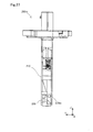
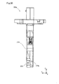
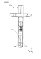
- FIG. 2 is an external view of the flow measurement device when viewed from a direction orthogonal to the opening direction of the inlet and the insertion direction
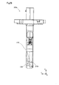
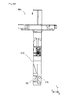
- FIG. 3 is an external view of the flow measuring device when viewed from the inlet side
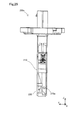
- FIG. 4 is an external view of the flow measuring device when viewed from the outlet side.
- FIG. 5 is a schematic cross-sectional view of the flow rate measuring device along the 5-5 cross section shown in FIG. FIG.
- FIG. 6 is a schematic cross-sectional view of the flow rate measuring device taken along the line 6-6 shown in FIG.
- FIG. 7 is a schematic cross-sectional view of the flow measurement device taken along the line 7-7 shown in FIG.
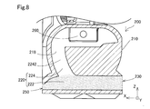
- FIG. 8 is an explanatory diagram of a water flow path in a forward flow state in the first embodiment
- FIG. 9 is an explanatory diagram of a flow path of water in a backflow state in the first embodiment
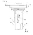
- FIG. 10 is a schematic side view of the flow measurement device according to the second embodiment
- FIG. 11 is a schematic top view of the flow measurement device according to the second embodiment
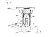
- FIG. 12 is a schematic cross-sectional view of the flow measurement device taken along the line 12-12 shown in FIG.
- FIG. 13 is a schematic cross-sectional view of the flow measurement device taken along the line 13-13 shown in FIG.
- FIG. 14 is a first schematic cross-sectional view of a projection in the first other embodiment
- FIG. 15 is a second schematic cross-sectional view of the protrusion in the first other embodiment
- FIG. 16 is a third schematic cross-sectional view of the protrusion in the first other embodiment
- FIG. 17 is a fourth schematic cross-sectional view of the protrusion in the first other embodiment
- FIG. 18 is a fifth schematic cross-sectional view of the projection in the first other embodiment
- FIG. 19 is a sixth schematic cross-sectional view of the protrusion in the first other embodiment
- FIG. 14 is a first schematic cross-sectional view of a projection in the first other embodiment
- FIG. 15 is a second schematic cross-sectional view of the protrusion in the first other embodiment
- FIG. 16 is a third schematic cross-sectional view of the protrusion in the first other embodiment
- FIG. 17 is
- FIG. 20 is a first explanatory view of a formation position of a communication hole in the second other embodiment
- FIG. 21 is a second explanatory view of the formation position of the communication hole in the second other embodiment
- FIG. 22 is a third explanatory view of the formation position of the communication hole in the second other embodiment
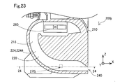
- FIG. 23 is a fourth explanatory diagram of the formation position of the communication hole in the second other embodiment
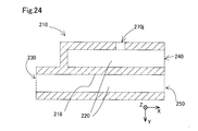
- FIG. 24 is a schematic cross-sectional view taken along the line 24-24 shown in FIG.
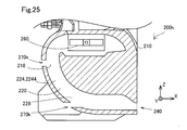
- FIG. 25 is a fifth explanatory view of the formation position of the communication hole in the second other embodiment
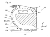
- FIG. 26 is a sixth explanatory diagram of the formation position of the communication hole in the second other embodiment
- FIG. 27 is a first explanatory view of the shape of the communication hole in the third other embodiment
- FIG. 28 is a second explanatory view of the shape of the communication hole in the third other embodiment
- FIG. 29 is a third explanatory view of the shape of the communication hole in the third other embodiment
- FIG. 30 is a fourth explanatory view of the shape of the communication hole in the third other embodiment
- FIG. 31 is a fifth explanatory view of the shape of the communication hole in the third other embodiment
- FIG. 32 is a sixth explanatory diagram of the shape of the communication hole in the third other embodiment
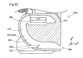
- FIG. 33 is a first explanatory view of the formation position of the convex portion in the fourth other embodiment
- FIG. 33 is a first explanatory view of the formation position of the convex portion in the fourth other embodiment
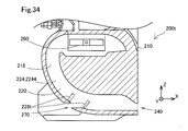
- FIG. 34 is a second explanatory view of the formation position of the protrusion in the fourth other embodiment
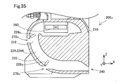
- FIG. 35 is a third explanatory view of the formation position of the protrusion in the fourth other embodiment
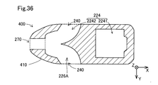
- FIG. 36 is a first cross-sectional view of a branch channel according to a fifth other embodiment
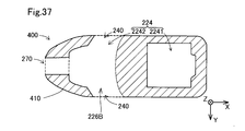
- FIG. 37 is a second cross-sectional view of the branch channel in the fifth other embodiment
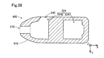
- FIG. 38 is a third cross-sectional view of the detection channel according to the fifth other embodiment.
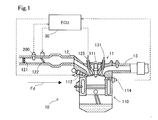
- a flow measurement device 200 is used for a combustion system 10 including an internal combustion engine 11.
- the combustion system 10 includes an internal combustion engine 11, a main flow path 12 and an exhaust flow path 13 formed by piping, and an ECU 30.
- the combustion system 10 is mounted on, for example, a gasoline-powered vehicle and is used as a driving device.
- the internal combustion engine 11 includes a combustion chamber 110, a spark plug 111, a fuel injection valve 112, a combustion pressure sensor 114, an intake valve 125, and an exhaust valve 131.
- the internal combustion engine 11 generates power by burning a mixed gas of air supplied through the main flow path 12 and fuel injected from the fuel injection valve 112.
- the spark plug 111 generates a spark discharge and ignites a mixed gas (mixed gas of fuel and air) in the combustion chamber 110.
- the fuel injection valve 112 injects fuel into the combustion chamber 110.
- the combustion pressure sensor 114 detects the combustion pressure in the combustion chamber 110.
- the main passage 12 and the exhaust passage 13 are connected to the combustion chamber 110.
- the main flow path 12 is a flow path that guides air to the combustion chamber 110.
- the exhaust passage 13 is a passage for discharging exhaust gas, which is a gas after combustion, from the combustion chamber 110.
- the main flow path 12 is provided with an air cleaner 121, a flow rate measuring device 200, and a throttle valve 122 in order from the upstream side.
- the air cleaner 121 removes dust in the air flowing through the main flow path 12.
- the throttle valve 122 adjusts the opening degree and adjusts the flow resistance in the main flow path 12.
- the flow measuring device 200 detects the flow rate of the intake air flowing through the main flow path 12.
- FIG. 1 the flow direction Fd of the intake air in the forward flow state in which the intake air flows from the upstream side to the downstream side of the main flow path 12 is indicated by an arrow.
- the ECU 30 is an arithmetic processing circuit including a processor, a storage medium such as a RAM, a ROM, and a flash memory, a microcomputer including an input / output unit, and a power supply circuit.
- the ECU 30 controls the opening of the throttle valve 122 and the amount of fuel injected from the fuel injection valve 112 using detection results obtained from the flow measurement device 200 and various sensors, for example, the combustion pressure sensor 114.
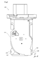
- the flow measurement device 200 includes a housing 210, an inlet 230, an outlet 240, an outlet 250, and a communication hole 270.
- the Z-axis which is a direction axis along the insertion direction when attaching the flow measurement device 200 to the main flow path 12
- the X-axis which is a direction axis along the opening direction of the inlet 230
- the insertion direction and the inlet
- a Y-axis which is a direction axis orthogonal to the opening direction of the portion 230.
- the opening direction of the entrance 230 is the ⁇ X axis direction in FIG.
- the insertion direction of the flow measurement device 200 is the ⁇ Z axis direction.
- the flow measurement device 200 is attached to the main channel 12 such that the inlet 230 faces the upstream side of the main channel 12. That is, when the flow measuring device 200 is attached to the main flow path 12, the + X-axis direction substantially coincides with the flow direction Fd in FIG. Further, the ⁇ Z axis direction substantially coincides with the direction of gravity when the flow measurement device 200 is attached to the main flow path 12.
- the outlet 240 is provided on a surface of the side surface of the housing 210 that faces the surface on which the inlet 230 is provided.
- the communication hole 270 is provided on the surface on which the inlet 230 is provided.
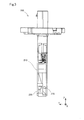
- the housing 210 is a housing made of a synthetic resin, and includes a sub-flow path forming section that forms the sub-flow path 220 therein, and a holding section that holds the flow rate detection section 260.
- the sub flow path 220 is a flow path through which a part of the intake air flowing through the main flow path 12 flows.
- the sub flow path 220 includes a discharge flow path 222 extending from the inlet 230 to the discharge port 250, and a detection flow path extending from the inlet 230 to the outlet 240 shown in FIG. 224.
- the detection channel 224 has an upstream detection channel 2242 (FIG. 5) and a downstream detection channel 2244 (FIG. 6).
- the upstream detection channel 2242 is a section of the detection channel 224 from the inlet 230 to the flow detection unit 260.
- the downstream detection flow path 2244 is a section of the detection flow path 224 from the flow rate detector 260 to the outlet 240.
- the discharge detection flow path 222 and the upstream detection flow path 2242 shown in FIG. 5 and the downstream detection flow path 2244 shown in FIG. 6 are separated from each other by the sub flow path wall 218.
- the flow rate detection unit 260 is provided in the middle of the sub flow path 220 and detects the flow rate of the fluid to be measured flowing through the sub flow path. It is preferable that the flow rate detector 260 can distinguish whether the flow direction of the fluid to be measured is the forward flow direction or the backward flow direction. In the present embodiment, the flow rate detection unit 260 employs a temperature difference method that is capable of distinguishing the flow direction. In the present embodiment, the flow detection unit 260 has a heater and a plurality of temperature sensors (not shown). The heater heats the fluid to be measured. The plurality of temperature sensors are arranged along the flow direction of the fluid to be measured, and each acquire the temperature of the fluid to be measured.
- the flow rate detection unit 260 of the present embodiment detects the flow rate from the temperature difference between the upstream side and the downstream side of the heater.
- the temperature sensors are arranged on both the upstream side and the downstream side of the heater.
- the temperature sensor is a temperature-sensitive resistor
- the heater is a heating resistor.
- the communication hole 270 is provided in the downstream detection flow channel 2244 of the sub flow channel 220, that is, between the flow detection unit 260 and the outlet 240. As shown in FIG. 3, in the present embodiment, the communication hole 270 is provided on the same side surface as the side surface on which the inlet 230 is provided. Further, as shown in FIG. 4, the opening of the communication hole 270 indicated by a broken line overlaps with the opening of the outlet 240 when viewed from the outlet 240 side.
- a convex portion 228 for reducing the cross-sectional area of the sub flow path 220 is provided between the communication hole 270 and the flow rate detection section 260.
- the protrusion 228 is provided at a position adjacent to the communication hole 270.
- the protrusion 228 in the present embodiment has a structure that protrudes from the sub-flow channel wall 218 to the inside of the downstream detection flow channel 2244. This is a step having a step shape.
- the stepped shape means a shape that changes the cross-sectional area of the sub flow path 220 discontinuously.
- the cross-sectional area of the flow channel at the position where the convex portion 228 is provided is smaller than the cross-sectional area of the flow channel at the position where the convex portion 228 is not provided.
- a part of the intake air in the forward flow state flowing from the upstream side to the downstream side of the main flow path 12 flows into the flow measuring device 200 from the inlet 230 as the fluid to be measured.
- the fluid to be measured flowing from the inlet 230 flows through the sub flow path 220.
- a part of the fluid to be measured flowing through the sub flow path 220 is discharged from a discharge port 250 provided on the upstream side of the sub flow path 220. Thereby, an increase in the pressure in the sub flow path 220 can be suppressed.
- the fluid to be measured flowing through the sub flow path 220 the fluid to be measured that has not been discharged from the discharge port 250 passes through the flow rate detection unit 260 and then flows out of the outlet 240 into the main flow path 12.
- the fluid to be measured flowing out of the outlet 240 into the main flow path 12 merges with the fluid to be measured flowing through the main flow path 12 without flowing into the flow measurement device 200, and is supplied to the internal combustion engine 11.
- the fluid to be measured flowing from the outlet 240 flows through the sub-flow path 220.
- a part of the fluid to be measured flowing in the sub flow path 220 is discharged from a communication hole 270 provided on the downstream side of the sub flow path 220. Thereby, an increase in the pressure in the sub flow path 220 can be suppressed.
- the fluid to be measured that has not been discharged from the communication hole 270 among the fluids to be measured flowing through the sub flow path 220 flows out of the inlet 230 into the main flow path 12 after passing through the flow rate detector 260.
- the fluid to be measured flowing out of the inlet 230 into the main flow path 12 joins the fluid to be measured flowing through the main flow path 12 without flowing into the flow measurement device 200, and flows to the upstream side of the main flow path 12.
- the backflow state occurs, for example, when the idling operation is performed in the combustion system 10.
- the combustion system 10 stops the flow of the intake air into the internal combustion engine 11 by closing the intake valve 125.
- the pressure of the intake air on the internal passage 11 side of the main passage 12 increases, the pressure on the downstream side of the main passage 12 becomes higher than on the upstream side, and a backflow occurs.
- the intake air contains water such as water droplets and water vapor. Therefore, moisture may flow into the sub flow path 220 together with the intake air as the fluid to be measured.
- moisture may flow into the sub flow path 220 together with the intake air as the fluid to be measured.
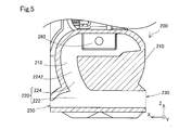
- the main path of the sub flow path 220 through which water, particularly a heavy water drop, flows is indicated by dots.
- the water flowing from the inlet 230 mainly flows out from the outlet 250 to the main flow channel 12. Since a heavy water droplet tends to move in the ⁇ Z-axis direction due to gravity, it is difficult to flow into the detection flow path 224 extending in the antigravity direction (+ Z-axis direction) where the flow rate detection unit 260 is disposed. is there.
- the main path of the sub flow path 220 through which water, particularly heavy water droplets, flows is indicated by dots.
- the water flowing from the outlet 240 mainly flows out from the communication hole 270 to the main flow channel 12. This is because a heavy water droplet tends to move in the ⁇ Z-axis direction due to gravity, and thus it is difficult to flow above the communication hole 270 of the detection channel 224 (in the + Z-axis direction).
- the flow path cross-sectional area of the area between the communication hole 270 and the flow rate detector 260 where the protrusion 228 is provided is smaller than the flow path cross-sectional areas of the other areas.
- the flow path resistance between the communication hole 270 and the flow detection unit 260 is larger than the flow path resistance between the communication hole 270 and the outlet 240.
- the inflow of moisture upward (in the + Z-axis direction) from the communication hole 270 of the detection flow path 224 is further suppressed.
- the communication hole 270 is provided on the surface opposite to the side surface on which the outlet 240 is provided.
- the outlet 240 faces the flow direction of the intake air in the reverse flow state. Therefore, the pressure outside the flow measurement device 200 via the communication hole 270 is smaller than the pressure outside the flow measurement device 200 via the outlet 240. Thereby, the movement of water from the outlet 240 to the communication hole 270 becomes smoother.
- the communication hole 270 is provided between the flow detection unit 260 and the outlet 240 in the sub flow path 220, and the sub flow path 220 and the main flow path 12 is communicated. Therefore, even when the measured fluid containing water droplets flows into the sub-flow path 220 from the outlet 240 due to the backflow, the flow measuring device 200 can detect the flowing measured fluid from the flow detecting unit 260 to the outlet 240 It can be discharged from the communication hole 270 provided on the side. Therefore, the possibility that water droplets adhere to the flow rate detection unit 260 is reduced. Therefore, a decrease in flow rate measurement accuracy in the flow rate measurement device 200 due to the attachment of water droplets to the flow rate detection unit 260 is suppressed.
- the flow path cross-sectional area of the sub flow path 220 in at least a part between the flow rate detection unit 260 and the communication hole 270 is determined by the communication hole 270 and the outlet.
- the flow path cross-sectional area of the sub flow path 220 with the portion 240 is smaller than the flow path cross-sectional area. Therefore, the flow path resistance in the area between the flow rate detector 260 and the communication hole 270 in the sub flow path 220 is larger than the flow path resistance in the area between the communication hole 270 and the outlet 240. Therefore, the inflow of the moisture flowing from the outlet 240 to the flow detector 260 side is suppressed.
- a convex portion 228 which is a step portion is provided between the flow rate detecting section 260 and the communication hole 270. For this reason, the moisture flowing from the outlet 240 side collides with the protrusion 228. Therefore, the flow measurement device 200 can more efficiently suppress the inflow of moisture from the protrusion 228 toward the flow detection unit 260 during the backflow.
- the protrusion 228 is provided on the communication hole 270 side in the section between the communication hole 270 and the flow detection unit 260. For this reason, at the time of backflow, the flow measurement device 200 can efficiently discharge the water whose flow from the protrusion 228 from the communication hole 270 to the flow detection unit 260 is suppressed. Further, in the present embodiment, since the protrusion 228 is provided at a position adjacent to the communication hole 270, the water can be discharged more efficiently.
- a flow measurement device 400 according to a second embodiment is different from the flow measurement device 200 according to the first embodiment in the structure of a housing 410.
- the same reference numeral is given and the detailed description is omitted.
- the housing 410 of the flow rate measuring device 400 is different from the housing 210 (FIG. 2) in the first embodiment in the appearance.
- two outlets 240 are provided (only one is shown in FIG. 10), and in addition to the outlets 240 provided on the side shown in FIG. Is provided.
- the two outlets 240 are provided on the side of the housing 410 that intersects the surface on which the inlet 230 is provided and the surface on which the discharge unit 250 is provided.
- a sub flow path 220 is formed inside the flow measuring device 200.
- the sub flow path 220 is provided with a flow rate detector 260.
- the housing 410 is a housing made of a synthetic resin, and has a sub-flow path forming section that forms the sub-flow path 220 therein, and a holding section that holds the flow rate detecting section 260.
- a communication hole 270 is formed in the downstream detection flow passage 2244 which is a section between the flow detection unit 260 and the outlet 240 in the sub flow passage 220.
- a protrusion 228 is provided between the communication hole 270 and the flow rate detector 260.
- the sub flow path 220 is a flow path through which a part of the intake air flowing through the main flow path 12 flows.
- the downstream detection flow passage 2244 on the downstream side of the flow detection unit 260 in the sub flow passage 220 has a branch flow passage 226 in which the flow passage is branched into two, as shown in FIG. are doing.
- the branch channels 226 are connected to two outlets 240, respectively.
- a communication hole is provided at substantially the same position where the outlet 240 is provided.
- the moisture flowing from the inlet 230 mainly flows out from the outlet 250 to the main flow channel 12. This is because, as in the case of the first embodiment, since a heavy water droplet tends to move in the ⁇ Z-axis direction due to gravity, it is located on the gravitational direction (+ Z-axis direction) side where the flow rate detector 260 is disposed. This is because it is difficult to flow into the detection flow path 224 extending to In the reverse flow state, the moisture flowing from the outlet 240 mainly flows out from the communication hole 270 to the main flow channel 12.
- the cross-sectional area of the flow passage in the region between the communication hole 270 and the flow detection unit 260 where the protrusion 228 is provided is reduced.
- the flow path resistance between the communication hole 270 and the flow detection unit 260 is larger than the flow path resistance between the communication hole 270 and the outlet 240. Accordingly, the inflow of moisture upward (in the + Z-axis direction) from the communication hole 270 of the detection channel 224 is further suppressed.
- the sub flow path 220 branches between the flow detection unit 260 and the plurality of outlets 240, and connects the plurality of outlets 240 and the communication hole 270. It has a branch channel 226. Further, at the time of backflow, the communication hole 270 is provided on the surface of the housing 410 on which the inlet 230 is provided, which is a wall surface on which the pressure is smaller than the pressure on the opposing surface. At the time of the backflow, the water can be more efficiently discharged from the sub flow path 220.
- the flow measurement devices 200 and 400 have, for example, a step-shaped convex portion 228 as shown in FIG.
- the shape of the protrusion 228 is not limited to this.
- the protrusion 228 may have any shape as long as the cross-sectional area of the detection channel 224 is reduced.
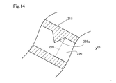
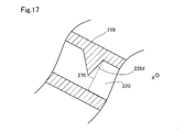
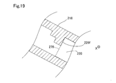
- an example of the shape of the convex portion 228 that can be employed will be described with reference to FIGS. 14 to 19.
- the protrusion 228 a may have a shape that is pointed toward the inside of the detection channel 224. Further, for example, as shown in FIG.
- the convex portion 228b has a shape having an inclined side surface and a planar end surface.
- the convex portion 228c may have a curved surface shape.
- the convex portion 228d has a shape that is sharp toward the inside of the detection flow channel 224, and the inclination angle is different between the upstream side and the downstream side of the detection flow channel 224. May be provided.
- the convex portion 228 e may protrude inward of the detection channel 224, and may have a curved shape such that a tip thereof faces the detection channel 224 side.
- the shape of the convex portion 228e is a shape more suitable for capturing moisture flowing from the downstream side.
- the protrusion 228f may have a plurality of steps. Note that the protrusion 228 does not necessarily need to be provided as long as the cross-sectional area of the detection channel 224 can be reduced.
- the detection flow path 224 may have a shape in which a part thereof becomes thinner.
- the formation position of the communication hole 270 can be changed as appropriate as long as it is provided in the section between the flow detection unit 260 and the outlet 240 in the detection channel 224. It is.
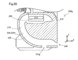
- an example of a position where the communication hole 270 can be employed will be described with reference to FIGS. 20 to 26, the flow channel structure of the flow measurement device 200 according to the first embodiment is employed. 20 to 26, the convex portion 228 is omitted for convenience of description.
- the flow measurement device 200g has a communication hole 270g on the downstream side, that is, on the side closer to the outlet 240 as compared with the flow measurement device 200 according to the first embodiment. Is also good.
- the opening of the communication hole 270g is formed on the distal end surface of the flow measuring device 200g on the insertion direction (-Z axis direction) side. Even in this case, in the backflow state, the pressure outside the communication hole 270 g becomes smaller than the pressure on the outlet 240 side. Therefore, the movement of water from the outlet 240 to the communication hole 270g is smooth.
- the flow measurement devices 200h and 200i have communication holes closer to the upstream side, that is, closer to the flow detection unit 260, than the flow measurement device 200 according to the first embodiment. It may have 270 g.
- the flow measurement device 200h illustrated in FIG. 21 has a communication hole 270h formed near the center of the downstream detection channel 2244.
- the flow measurement device 200i illustrated in FIG. 22 has a communication hole 270i formed upstream from the center of the downstream detection flow channel 2244.
- the openings of the communication holes 270h and 270i shown in FIGS. 21 and 22 are provided on the side surface of the flow measuring devices 200h and 200i where the inlet 230 is provided.
- the flow measurement device 270j may have a communication hole 270j provided on a side surface intersecting the side surface provided with the inlet 230 and the front end surface.
- the flow measurement device 270j has a communication hole 270j that opens in the ⁇ Y-axis direction, that is, has a direction of opening that intersects with the direction in which the sub flow path 220 extends. Even in this case, in the backflow state, the pressure outside the communication hole 270j becomes smaller than the pressure at the outlet 240 side. Therefore, the movement of moisture from the outlet 240 to the communication hole 270j is smooth.
- the number of communication holes 270 is not limited to one.
- the flow measurement device 200k may have two communication holes 270k.
- the flow measurement device 200l may have three communication holes 270l.
- the shape of the opening of the communication hole 270 is square, but the shape of the opening of the communication hole 270 is not limited to a square.
- the flow measurement device 200m may have a communication hole 270m having a circular opening.
- the flow measurement device 200n may have a communication hole 270n having a triangular opening shape.
- the flow rate measurement device 200o may have a communication hole 270o having a rhombic opening. Further, as shown in FIG.
- the distal end side ( ⁇ Z axis direction side) of the flow measurement device 200p of the opening shape extends in the horizontal direction, and the base end side (+ Z axis direction side). May have a communication hole 270p having an arc shape.
- the flow rate measuring device 200q may have a communication hole 270q having a cross shape of an opening.
- the flow measurement device 200r may have a polygonal communication hole 270r having four or more vertices, specifically, a hexagonal communication hole 270r.
- the flow measurement devices 200 and 400 include the protrusion 228 formed between the communication hole 270 and the flow detection unit 260 and adjacent to the communication hole 270. Have.
- the formation position of the protrusion 228 is not limited to this.
- the flow measurement device 200 s may have a protrusion 228 s formed between the communication hole 270 and the outlet 240.
- the flow measurement device 200t has two protrusions 228t, and a protrusion 2281t formed between the communication hole 270 and the flow detection unit 260, And a convex portion 2282t formed between the outlet portion 240 and the outlet portion 240.
- the flow measurement device 200u may have a protrusion 228u near each of the plurality of communication holes 270u.
- the flow path structure of the flow measurement device 200 according to the first embodiment is used, but the flow measurement device 400 according to the second embodiment is used.
- the flow path structure described above can be similarly changed.
- a flow measurement device 400 according to a second embodiment has a branch flow path 226 having the shape shown in FIG. 13, but connects a flow detection unit 260 and two outlets 240. If possible, it may have a branch channel 226 of a different shape.
- the branch channel 226A has a curved wall surface in a region where the detection channel 224 branches.
- the branch flow path 226B has a pointed wall surface in a region where the detection flow path 224 branches.
- the number of outlets 240 included in the flow measurement device 400 according to the second embodiment is not limited to two. For example, three or more outlets 240 may be provided.
- the flow measurement device 400 may have a branch flow path 226 branched into three or more so that three or more outlets 240 and the flow detection part 260 can be connected.
- the number of the outlet 240 may be one.
- the detection channel 224 may have a channel structure having no branch.
- the discharge port 250 only needs to be provided on the wall surface of the housings 210 and 410 whose pressure is lower than the pressure on the surface of the housings 210 and 410 facing the flow direction during backflow.
- the outlet 250 may be provided, for example, on a surface of the housings 210 and 410 facing the flow direction, for example, a distal end surface.
- the flow measurement devices 200 and 400 may have different flow path structures.
- the number of outlets 240 may be three or more.
- the number of the inlet portions 230 may be two or more.
- the flow measurement device 200 may not include the outlet 250.
- the flow rate measuring devices 200 and 400 are used in the combustion system 10, but may be used in other than the combustion system 10.
- the flow measurement device 200 may be attached to an air supply pipe of an air supply system in a fuel cell system using air as an oxidant gas.
- the flow measurement devices 200 and 400 have a structure for reducing the flow path cross-sectional area of the detection flow path 224, for example, a convex portion 228.
- the flow measurement devices 200 and 400 need not have a structure for reducing the flow path cross-sectional area of the detection flow path 224.
- the present disclosure is not limited to the above-described embodiments, and can be implemented with various configurations without departing from the spirit thereof.
- the technical features in the present embodiment corresponding to the technical features in the respective embodiments described in the summary of the invention may be used to solve some or all of the above-described problems, or to achieve the above-described effects. In order to achieve some or all of them, replacements and combinations can be appropriately performed. Unless the technical features are described as essential in the present specification, they can be deleted as appropriate.
Abstract
流量測定装置は、流量測定装置の主流路への挿入方向に延びる側面を有するハウジングと、ハウジングの内部に形成され、主流路を流れる被検出流体の一部を流通させる副流路と、側面に設けられ、主流路を流れる被計測流体を副流路内へと流入させる入口部と、副流路内を流れる被計測流体を主流路へと流出させる出口部と、副流路のうち入口部と出口部との間に設けられ、副流路を流れる被計測流体の流量を検出する流量検出部と、副流路のうち流量検出部と出口部との間に設けられ、副流路と主流路とを連通させる連通孔と、を備える。
Description
本出願は、2018年8月8日に出願された日本出願番号2018-149049号に基づくもので、ここにその記載内容を援用する。
本開示は、流量計測装置に関する。
主流路に配置されるハウジングと、ハウジングに設けられた副流路とを備え、主流路を流通する被計測流体の流量を計測する熱式流量計である流量計測装置が知られている(例えば特許文献1)。この流量計測装置において、副流路のうち流量検出部の上流側には、副流路に流入する水滴を排出するための水抜き穴が設けられている。
従来の流量計測装置において、被計測流体の逆流が生じた場合には、順流時における出口から副流路に水滴が流入するおそれがある。出口から水滴が流入した場合には、水滴が水抜き穴から排出される前に、流量検出部に到達する場合がある。このため、流量測定部に水滴が付着するおそれがある。流量検出部に水滴が付着した場合には、流量検出部による流量の検出精度が低減するおそれがある。
本開示は、以下の形態として実現することが可能である。
本開示の一形態によれば、被計測流体が流れる主流路の外部側から挿入された状態で前記主流路に取り付けられ、前記主流路における前記被計測流体の流量を測定する流量測定装置が提供される。この流量測定装置は、前記流量測定装置の前記主流路への挿入方向に延びる側面を有するハウジングと、前記ハウジングの内部に形成され、前記主流路を流れる前記被検出流体の一部を流通させる副流路と、前記側面に設けられ、前記主流路を流れる前記被計測流体を前記副流路内へと流入させる入口部と、前記副流路内を流れる前記被計測流体を前記主流路へと流出させる出口部と、前記副流路のうち前記入口部と前記出口部との間に設けられ、前記副流路を流れる前記被計測流体の流量を検出する流量検出部と、前記副流路のうち前記流量検出部と前記出口部との間に設けられ、前記副流路と前記主流路とを連通させる連通孔と、を備える。
この形態によれば、流量測定装置は、副流路のうち流量検出部と出口部との間に設けられ、副流路と主流路とを連通させる連通孔と、を備えるので、出口部から水滴を含んだ被計測流体が副流路に流入した場合であっても、流入した被計測流体を流量検出部より出口側に備えられた連通孔から排出できる。このため、流量検出部に水滴が付着する可能性が低減される。したがって、流量検出部に水滴が付着することに起因する、流量測定装置における流量の検出精度の低減が抑制される。
本開示についての上記目的およびその他の目的、特徴や利点は、添付の図面を参照しながら下記の詳細な記述により、より明確になる。その図面は、
図1は、第1実施形態に係る流量測定装置が使用された燃焼システムの模式図であり、
図2は、流量測定装置を入口部の開口方向と挿入方向とに直交する方向から見た場合の外観図であり、
図3は、流量測定装置を入口部側から見た場合の外観図であり、
図4は、流量測定装置を出口部側から見た場合の外観図であり、
図5は、図4に示された5-5断面における流量測定装置の模式断面図であり、
図6は、図4に示された6-6断面における流量測定装置の模式断面図であり、
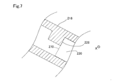
図7は、図6に示された7-7断面における流量測定装置の模式断面図であり、
図8は、第1実施形態における順流状態における水分の流通経路の説明図であり、
図9は、第1実施形態における逆流状態における水分の流通経路の説明図であり、
図10は、第2実施形態に係る流量測定装置の模式側面図であり、
図11は、第2実施形態に係る流量測定装置の模式天面図であり、
図12は、図11に示された12-12断面における流量測定装置の模式断面図であり、
図13は、図12に示された13-13断面における流量測定装置の模式断面図であり、
図14は、第1の他の実施形態における凸部の第1の模式断面図であり、
図15は、第1の他の実施形態における凸部の第2の模式断面図であり、
図16は、第1の他の実施形態における凸部の第3の模式断面図であり、
図17は、第1の他の実施形態における凸部の第4の模式断面図であり、
図18は、第1の他の実施形態における凸部の第5の模式断面図であり、
図19は、第1の他の実施形態における凸部の第6の模式断面図であり、
図20は、第2の他の実施形態における連通孔の形成位置の第1の説明図であり、
図21は、第2の他の実施形態における連通孔の形成位置の第2の説明図であり、
図22は、第2の他の実施形態における連通孔の形成位置の第3の説明図であり、
図23は、第2の他の実施形態における連通孔の形成位置の第4の説明図であり、
図24は、図23に示された24-24断面における模式断面図であり、
図25は、第2の他の実施形態における連通孔の形成位置の第5の説明図であり、
図26は、第2の他の実施形態における連通孔の形成位置の第6の説明図であり、
図27は、第3の他の実施形態における連通孔の形状の第1の説明図であり、
図28は、第3の他の実施形態における連通孔の形状の第2の説明図であり、
図29は、第3の他の実施形態における連通孔の形状の第3の説明図であり、
図30は、第3の他の実施形態における連通孔の形状の第4の説明図であり、
図31は、第3の他の実施形態における連通孔の形状の第5の説明図であり、
図32は、第3の他の実施形態における連通孔の形状の第6の説明図であり、
図33は、第4の他の実施形態における凸部の形成位置の第1の説明図であり、
図34は、第4の他の実施形態における凸部の形成位置の第2の説明図であり、
図35は、第4の他の実施形態における凸部の形成位置の第3の説明図であり、
図36は、第5の他の実施形態における分岐流路の第1の断面図であり、
図37は、第5の他の実施形態における分岐流路の第2の断面図であり、
図38は、第5の他の実施形態における検出流路の第3の断面図である。
A.第1実施形態
図1に示した様に、実施形態に係る流量測定装置200は、内燃機関11を備える燃焼システム10に用いられる。燃焼システム10は、内燃機関11と、配管により形成された主流路12及び排気流路13と、ECU30と、を備える。燃焼システム10は、例えば、ガソリン車に搭載され、駆動装置として用いられる。
図1に示した様に、実施形態に係る流量測定装置200は、内燃機関11を備える燃焼システム10に用いられる。燃焼システム10は、内燃機関11と、配管により形成された主流路12及び排気流路13と、ECU30と、を備える。燃焼システム10は、例えば、ガソリン車に搭載され、駆動装置として用いられる。
内燃機関11は、燃焼室110と、点火プラグ111と、燃料噴射弁112と、燃焼圧センサ114と、吸気弁125と、排気弁131と、を備える。内燃機関11は、主流路12を介して供給される空気と、燃料噴射弁112から噴射される燃料との混合ガスを燃焼させることによって動力を発生させる。点火プラグ111は、火花放電を生じさせて燃焼室110内の混合ガス(燃料と空気との混合ガス)に着火する。燃料噴射弁112は、燃焼室110内に対して燃料を噴射する。燃焼圧センサ114は、燃焼室110内の燃焼圧を検出する。
燃焼室110には、主流路12と排気流路13とが接続されている。主流路12は、空気を燃焼室110に導く流路である。排気流路13は、燃焼された後の気体である排気ガスを燃焼室110から排出する流路である。
主流路12には、上流側から順にエアクリーナ121と、流量測定装置200と、スロットルバルブ122と、が備えられている。エアクリーナ121は、主流路12を流通する空気中の塵埃を除去する。スロットルバルブ122は、開度を調整し、主流路12における流路抵抗を調整する。流量測定装置200は、主流路12内を流通する吸入空気の流量を検出する。図1には、吸入空気が主流路12の上流側から下流側へと流通する順流状態における吸入空気の流通方向Fdが矢印によって示されている。
ECU30は、プロセッサやRAMやROMやフラッシュメモリ等の記憶媒体と、入出力部を含むマイクロコンピュータと、電源回路と、を含む演算処理回路である。ECU30は、流量測定装置200や各種センサ、例えば燃焼圧センサ114、から取得される検出結果を用いて、スロットルバルブ122の開度や燃料噴射弁112から噴射される燃料噴射量を制御する。
図2から図4に示した様に、流量測定装置200は、ハウジング210と、入口部230と、出口部240と、排出口部250と、連通孔270と、を備える。図2では、流量測定装置200を主流路12に取り付ける際の挿入方向に沿った方向軸であるZ軸と、入口部230の開口方向に沿った方向軸であるX軸と、挿入方向と入口部230の開口方向とに直交する方向軸であるY軸と、が示されている。入口部230の開口方向は、図2において、-X軸方向である。また、流量測定装置200の挿入方向は、-Z軸方向である。流量測定装置200は、入口部230が主流路12の上流側を向くように主流路12に取り付けられる。つまり、流量測定装置200が主流路12に取り付けられた場合において、+X軸方向は、図1における流通方向Fdと概ね一致する。また、-Z軸方向は、流量測定装置200が主流路12に取り付けられた場合において、重力方向と概ね一致する。本実施形態において、出口部240は、それぞれハウジング210の側面のうち入口部230が設けられた面に対向する面に設けられている。また、本実施形態において、連通孔270は、入口部230が設けられた面に設けられている。
図5及び図6に示した様に、流量測定装置200の内部には、副流路220が形成されている。ハウジング210は、合成樹脂製の筐体であり、内部に副流路220を形成する副流路形成部と、流量検出部260の保持を行う保持部と、を有する。
副流路220は、主流路12を流れる吸入空気の一部を流通させる流路である。副流路220は、図5に示した様に、入口部230から排出口部250へと向かう排出流路222と、入口部230から図6に示した出口部240側へと延びる検出流路224とを有する。検出流路224は、上流側検出流路2242(図5)と下流側検出流路2244(図6)とを有している。上流側検出流路2242は、検出流路224のうち入口部230から流量検出部260までの区間である。下流側検出流路2244は、検出流路224のうち流量検出部260から出口部240までの区間である。図5に示された排検出流路222及び上流側検出流路2242と、図6に示された下流側検出流路2244とは、互いに副流路壁218によって隔てられている。
流量検出部260は、副流路220の途中に設けられ、副流路を流れる被計測流体の流量を検出する。流量検出部260は、被計測流体の流通方向が順流方向か逆流方向であるかを区別可能であることが好ましい。本実施形態において、流量検出部260には、流通方向の区別が可能な方式である温度差方式が採用されている。本実施形態において、流量検出部260は、図示しない加熱ヒータ及び複数の温度センサを有する。加熱ヒータは被計測流体を加熱する。複数の温度センサは、被計測流体の流通方向に沿って配置され、それぞれ被計測流体の温度を取得する。本実施形態の流量検出部260は、加熱ヒータの上流側と下流側との温度差から流量を検出する。温度センサは、加熱ヒータの上流側と下流側の両方に配置されている。本実施形態において、温度センサは、感温抵抗体であり、加熱ヒータは、発熱抵抗体である。
図6に示した様に、連通孔270は、副流路220のうち下流側検出流路2244、つまり流量検出部260と出口部240との間に設けられている。図3に示した様に、本実施形態において、連通孔270は、入口部230が設けられた側面と同様の側面に設けられている。また、図4に示した様に、破線によって示された連通孔270の開口は、出口部240側から見た場合において、出口部240の開口と重なっている。
図6に示した様に、連通孔270と流量検出部260との間には、副流路220の流路断面積を小さくする凸部228が設けられている。本実施形態において、凸部228は、連通孔270に隣接した位置に設けられている。図7に示した様に、本実施形態における凸部228は、副流路壁218から下流側検出流路2244の内方に突出した構造であり。段差形状を有する段差部である。段差形状とは、副流路220の流路断面積を不連続に変化させる形状を意味する。凸部228が設けられた位置における流路断面積は、凸部228を有さない位置における流路断面積より小さくなっている。
以下では、図5と図6を用いて吸入空気の流通経路を説明する。主流路12(図1)の上流側から下流側へと流れる順流状態の吸入空気の一部は、被計測流体として入口部230から流量測定装置200の内部に流入する。入口部230から流入した被計測流体は副流路220内を流通する。副流路220内を流通する被計測流体の一部は、副流路220の上流側に設けられた排出口部250から排出される。これにより、副流路220内の圧力の上昇を抑制できる。副流路220内を流通する被計測流体のうち排出口部250から排出されなかった被計測流体は、流量検出部260を通過した後に、出口部240から主流路12に流出する。出口部240から主流路12に流出した被計測流体は、流量測定装置200に流入することなく主流路12を流通する被計測流体と合流し、内燃機関11へと供給される。
一方で主流路12の下流側から上流側へと流れる逆流状態の吸入空気の一部は、被計測流体として出口部240から流量測定装置200の内部に流入する。出口部240から流入した被計測流体は副流路220内を流通する。副流路220内を流通する被計測流体の一部は、副流路220の下流側に設けられた連通孔270から排出される。これにより、副流路220内の圧力の上昇を抑制できる。副流路220内を流通する被計測流体のうち連通孔270から排出されなかった被計測流体は、流量検出部260を通過した後に、入口部230から主流路12に流出する。入口部230から主流路12に流出した被計測流体は、流量測定装置200に流入することなく主流路12を流通する被計測流体と合流し、主流路12の上流側へと流れる。逆流状態は、例えば燃焼システム10においてアイドリング運転が実行された場合に発生する。アイドリング運転が実行された場合において、燃焼システム10は、吸気弁125を閉じることによって、内燃機関11への吸入空気の流入を停止させる。この場合には、主流路12の内燃機関11側における吸入空気の圧力が上昇し、主流路12の上流側よりも下流側の圧力が高くなり、逆流が発生する。
吸入空気には、水滴や水蒸気等の水分が含まれている。このため、副流路220内には、被計測流体としての吸入空気とともに、水分が流入するおそれがある。以下では、図8を用いて、順流状態において、副流路220に水分が流入した際の様子を説明する。
図8では、副流路220のうち水分、特に重量の大きい水滴、が流通する主な経路がドットによって示されている。図8に示した様に、入口部230から流入した水分は、主に、排出口部250から主流路12へと流出する。重量の大きい水滴は、重力によって-Z軸方向に移動する傾向があるため、流量検出部260が配置された反重力方向(+Z軸方向)側に延びる検出流路224には流入しづらいためである。
図4に示した様に、流量測定装置200を出口部240側から見た場合において、排出口部250と入口部230とが重なるように形成されている。このため、入口部230から流入した水分が排出口部250に円滑に移動する。また、排出口部250の開口の中心を通り、X軸方向に沿って延びる開口軸は、入口部230の開口と重なっている。この場合には、入口部230から排出口部250への水分の移動がより円滑になる。
また、逆流状態である場合にも、順流状態の場合と同様に、水分が副流路220内に流入するおそれがある。以下では、図9を用いて、逆流状態において、副流路220に水分が流入した際の様子を説明する。
図9においても、図8と同様に、副流路220のうち水分、特に重量の大きい水滴が流通する主な経路がドットによって示されている。図9に示した様に、出口部240から流入した水分は、主に、連通孔270から主流路12へと流出する。これは、重量の大きい水滴は、重力によって-Z軸方向に移動する傾向があるため、検出流路224の連通孔270より上側(+Z軸方向)には流入しづらいためである。また、本実施形態では、連通孔270と流量検出部260との間のうち凸部228が設けられた領域の流路断面積が、他の領域の流路断面積よりも小さい。このため、連通孔270と流量検出部260との間における流路抵抗が連通孔270と出口部240との間における流路抵抗より大きい。これにより、検出流路224の連通孔270より上側(+Z軸方向)への水分の流入がより抑制される。
図4に示した様に、流量測定装置200を出口部240側から見た場合において、連通孔270と出口部240とが重なるように形成されている。このため、出口部240から流入した水分が連通孔270に円滑に移動する。また、連通孔270の開口の中心を通り、X軸方向に沿って延びる開口軸は、出口部240の開口と重なっている。この場合には、出口部240から連通孔270への水分の移動がより円滑になる。
また、吸入空気が逆流している場合において、出口部240が設けられた側面とは反対側の面に、連通孔270が設けられている。出口部240は、逆流状態において吸入吸気の流通方向と対向する。このため、連通孔270を介した流量測定装置200の外側の圧力は、出口部240を介した流量測定装置200の外側の圧力より小さい。これにより、出口部240から連通孔270への水分の移動がより円滑になる。
以上説明した第1実施形態に係る流量測定装置200によれば、連通孔270は、副流路220のうち流量検出部260と出口部240との間に設けられ、副流路220と主流路12とを連通させると、を備える。このため、流量測定装置200は、逆流によって出口部240から水滴を含んだ被計測流体が副流路220に流入した場合であっても、流入した被計測流体を流量検出部260より出口部240側に備えられた連通孔270から排出できる。このため、流量検出部260に水滴が付着する可能性が低減される。したがって、流量検出部260に水滴が付着することに起因する、流量測定装置200における流量の測定精度の低減が抑制される。
また以上説明した第1実施形態に係る流量測定装置200によれば、流量検出部260と連通孔270との間の少なくとも一部における副流路220の流路断面積は、連通孔270と出口部240との間における副流路220の流路断面積より小さい。このため、副流路220のうち流量検出部260と連通孔部270との間の領域における流路抵抗は、連通孔270と出口部240との間の領域における流路抵抗より大きい。したがって、出口部240から流入した水分の流量検出部260側への流入が抑制される。また、流量検出部260と連通孔270との間には、段差部である凸部228が設けられている。このため、出口部240側から流入した水分は、凸部228に衝突する。したがって、流量測定装置200は、逆流時における凸部228より流量検出部260側への水分の流入をより効率的に抑制できる。
また以上説明した第1実施形態に係る流量測定装置200によれば、凸部228は、連通孔270と流量検出部260との間の区間のうち連通孔270側に設けられている。このため、逆流時において、流量測定装置200は、連通孔270からの凸部228より流量検出部260側への流入を抑制された水分を効率的に排出できる。さらに本実施形態において、凸部228は、連通孔270に隣接した位置に設けられているため、水分をより効率的に排出できる。
B.第2実施形態
第2実施形態に係る流量測定装置400は、第1実施形態に係る流量測定装置200と、ハウジング410の構造が異なる。以下において、以下において、第1実施形態と同様の構成を説明する場合には、同様の符号を付し、詳細な説明を省略する。
第2実施形態に係る流量測定装置400は、第1実施形態に係る流量測定装置200と、ハウジング410の構造が異なる。以下において、以下において、第1実施形態と同様の構成を説明する場合には、同様の符号を付し、詳細な説明を省略する。
図10に示した様に、流量測定装置400のハウジング410は、第1実施形態におけるハウジング210(図2)と、外観形状が異なる。例えば、本実施形態において、出口部240は2つ(図10では1つのみ開示)設けられ、図10において示された側面側に設けられた出口部240に加えて、反対側の側面にも設けられている。2つの出口部240は、それぞれハウジング410の側面のうち入口部230が設けられた面及び排出部250が設けられた面に交差する面に設けられている。
図11に示した様に、流量測定装置400を挿入方向の基端側(+Z軸方向側)から見た場合において、ハウジング410には、主流路12に固定するために用いられるためのボルト挿入口280が設けられている。
図12に示した様に、流量測定装置200の内部には、副流路220が形成されている。副流路220には、流量検出部260が備えられている。第1実施形態におけるハウジング210と同様に、ハウジング410は、合成樹脂製の筐体であり、内部に副流路220を形成する副流路形成部と、流量検出部260の保持を行う保持部と、を有する。図12に示した様に、副流路220のうち流量検出部260と出口部240との間の区間である下流側検出流路2244には、連通孔270が形成されている。また、連通孔270と流量検出部260との間には、凸部228が設けられている。
副流路220は、主流路12を流れる吸入空気の一部を流通させる流路である。本実施形態において、副流路220のうち流量検出部260の下流側である下流側検出流路2244では、図13に示した様に、流路が2つに分岐した分岐流路226を有している。分岐流路226は、それぞれ2つの出口部240に接続されている。また、挿入方向に沿った方向であるZ軸方向において、出口部240が設けられた概ね同じ位置に、連通孔が設けられている。
順流状態において、入口部230から流入した水分は、主に、排出口部250から主流路12へと流出する。これは、第1実施形態の場合と同様に、重量の大きい水滴は、重力によって-Z軸方向に移動する傾向があるため、流量検出部260が配置された重力方向上(+Z軸方向)側に延びる検出流路224には流入しづらいためである。また、逆流状態において、出口部240から流入した水分は、主に、連通孔270から主流路12へと流出する。これは、重量の大きい水滴は、重力によって-Z軸方向に移動する傾向があるため、検出流路224の連通孔270より上側(+Z軸方向)には流入しづらいためである。また、本実施形態では、連通孔270と流量検出部260との間のうち凸部228が設けられた領域の流路断面積が縮小されている。このため、連通孔270と流量検出部260との間における流路抵抗が連通孔270と出口部240との間における流路抵抗より大きい。これにより、検出流路224の連通孔270より上側(+Z軸方向)への水分の流入がより抑制される。
以上説明した第2実施形態に係る流量測定装置400によれば、上記第1実施形態と同様の構成を有する点において、同様の効果を奏する。また、第2実施形態に係る流量測定装置400において、副流路220は、流量検出部260と複数の出口部240との間で分岐し、複数の出口部240と連通孔270とを連通させる分岐流路226を有している。また、逆流時において、連通孔270が、ハウジング410のうち対向する面の圧力より圧力が小さくなる壁面である入口部230が設けられた面に設けられている、このため、流量測定装置400は、逆流時において、副流路220から水分をより効率的に排出できる。
C.他の実施形態
C1.第1の他の実施形態
上記実施形態において、流量測定装置200、400は、例えば図7に示した様な段差形状の凸部228を有している。しかし、凸部228の形状は、これに限定されない。凸部228は、検出流路224の流路断面積を減少させる形状であればよい。以下では、図14から図19を用いて、採用可能な凸部228の形状の一例を説明する。例えば、図14に示した様に、凸部228aは、検出流路224の内方に向かって尖った形状であってもよい。また例えば、図15に示した様に、凸部228bは、傾斜した側面と、平面形状の端面と、を有する形状である。また例えば、図16に示した様に、凸部228cは、曲面形状を有していてもよい。また例えば、図17に示した様に、凸部228dは、検出流路224の内方に向かって尖った形状であって、傾斜角度が検出流路224の上流側と下流側とで異なる形状を有していても良い。また例えば、図18に示した様に、凸部228eは、検出流路224の内方に向かって突出し、先端が検出流路224側を向くように湾曲した形状であってもよい。凸部228eの形状は、下流側から流入する水分の捕捉により適した形状である。図19に示した様に、凸部228fは、複数の段差部分を有していても良い。なお、検出流路224の流路断面積を減少させることが可能であれば、必ずしも凸部228を有している必要は無い。例えば、凸部228に代えて、検出流路224の一部が細くなる形状を有していても良い。
C2.第2の他の実施形態
上記実施形態において、連通孔270の形成位置は、検出流路224のうち流量検出部260と出口部240との間の区間に設けられている限りにおいて、適宜変更可能である。以下では、図20から図26を用いて、採用可能な連通孔270の形成位置の一例を説明する。なお、図20から図26では、第1実施形態に係る流量測定装置200の流路構造が採用されている。また、図20から図26では、説明の便宜上、凸部228を省略している。例えば、図20に示した様に、流量測定装置200gは、第1実施形態に係る流量測定装置200と比べて、より下流側、つまり出口部240により近い側に連通孔270gを有していてもよい。この場合において、連通孔270gの開口は、流量測定装置200gの挿入方向(-Z軸方向)側の先端面に形成されている。この場合であっても、逆流状態において、連通孔270gの外側の圧力は、出口部240側の圧力より小さくなる。このため、出口部240から連通孔270gへの水分の移動が円滑になる。
上記実施形態において、連通孔270の形成位置は、検出流路224のうち流量検出部260と出口部240との間の区間に設けられている限りにおいて、適宜変更可能である。以下では、図20から図26を用いて、採用可能な連通孔270の形成位置の一例を説明する。なお、図20から図26では、第1実施形態に係る流量測定装置200の流路構造が採用されている。また、図20から図26では、説明の便宜上、凸部228を省略している。例えば、図20に示した様に、流量測定装置200gは、第1実施形態に係る流量測定装置200と比べて、より下流側、つまり出口部240により近い側に連通孔270gを有していてもよい。この場合において、連通孔270gの開口は、流量測定装置200gの挿入方向(-Z軸方向)側の先端面に形成されている。この場合であっても、逆流状態において、連通孔270gの外側の圧力は、出口部240側の圧力より小さくなる。このため、出口部240から連通孔270gへの水分の移動が円滑になる。
また、図21及び図22に示した様に、流量測定装置200h、200iは、第1実施形態に係る流量測定装置200と比べて、より上流側、つまり流量検出部260により近い側に連通孔270gを有していてもよい。例えば、図21に示した流量測定装置200hは、下流側検出流路2244の中央付近に形成された連通孔270hを有している。また例えば、図22に示した流量測定装置200iは、下流側検出流路2244の中央より上流側に形成された連通孔270iを有している。図21及び図22に示した連通孔270h、270iの開口は、流量測定装置200h、200iの入口部230が設けられた側面に設けられている。この場合であっても、逆流状態において、連通孔270h、270iの外側の圧力は、出口部240側の圧力より小さくなる。このため、出口部240から連通孔270h、270iへの水分の移動が円滑になる。また、連通孔270h、270iが流量測定装置200h、200iの入口部230が設けられた側面に設けられている場合には、水分が、出口部240から上流側に向かって移動する際に作用する慣性によって、連通孔270h、270iから流出する。このため、出口部240から連通孔270h、270iへの水分の移動がより円滑になる。
また、図23に示した様に、流量測定装置270jは、入口部230が設けられた側面と先端面とに交差する側面に設けられた連通孔270jを有していても良い。図24に示した様に、流量測定装置270jは、-Y軸方向に向かって開口する、つまり副流路220が延びる方向と交差する開口方向を有する連通孔270jを有する。この場合であっても、逆流状態において、連通孔270jの外側の圧力は、出口部240側の圧力より小さくなる。このため、出口部240から連通孔270jへの水分の移動が円滑になる。
また、図25及び図26に示した様に連通孔270の数は、1つに限定されない。例えば、図25に示した様に、流量測定装置200kは、2つの連通孔270kを有していてもよい。また、図26に示した様に、流量測定装置200lは、3つの連通孔270lを有していてもよい。
C3.第3の他の実施形態
上記実施形態において、連通孔270の開口の形状は、四角形であるが、連通孔270の開口の形状は四角形に限定されない。以下では、図27から図32を用いて、採用可能な連通孔270の開口の形状の一例を説明する。例えば、図27に示した様に、流量測定装置200mは、開口の形状が円形の連通孔270mを有していても良い。また、図28に示した様に、流量測定装置200nは、開口の形状が三角形の連通孔270nを有していても良い。また、図29に示した様に、流量測定装置200oは、開口の形状が菱形の連通孔270oを有していても良い。また、図30に示した様に、流量測定装置200pは、開口の形状のうち流量測定装置200pの先端側(-Z軸方向側)が水平方向に延び、基端側(+Z軸方向側)が円弧状の形状を有する連通孔270pを有していても良い。また、図31に示した様に、流量測定装置200qは、開口の形状が十字形の連通孔270qを有していても良い。また、図32に示した様に、流量測定装置200rは、開口の形状が4つ以上の頂点を有する多角形、具体的には六角形の連通孔270rを有していても良い。
上記実施形態において、連通孔270の開口の形状は、四角形であるが、連通孔270の開口の形状は四角形に限定されない。以下では、図27から図32を用いて、採用可能な連通孔270の開口の形状の一例を説明する。例えば、図27に示した様に、流量測定装置200mは、開口の形状が円形の連通孔270mを有していても良い。また、図28に示した様に、流量測定装置200nは、開口の形状が三角形の連通孔270nを有していても良い。また、図29に示した様に、流量測定装置200oは、開口の形状が菱形の連通孔270oを有していても良い。また、図30に示した様に、流量測定装置200pは、開口の形状のうち流量測定装置200pの先端側(-Z軸方向側)が水平方向に延び、基端側(+Z軸方向側)が円弧状の形状を有する連通孔270pを有していても良い。また、図31に示した様に、流量測定装置200qは、開口の形状が十字形の連通孔270qを有していても良い。また、図32に示した様に、流量測定装置200rは、開口の形状が4つ以上の頂点を有する多角形、具体的には六角形の連通孔270rを有していても良い。
C4.第4の他の実施形態
上記実施形態において、流量測定装置200、400は、連通孔270と流量検出部260との間であって、連通孔270と隣接する位置に形成された凸部228を有する。しかし、凸部228の形成位置は、これに限定されない。例えば、図33に示した様に、流量測定装置200sは、連通孔270と出口部240との間に形成された凸部228sを有していてもよい。また、例えば、図34に示した様に、流量測定装置200tは、2つの凸部228tを有し、連通孔270と流量検出部260との間に形成された凸部2281tと、連通孔270と出口部240との間に形成された凸部2282tと、を有していてもよい。また、図35に示した様に、流量測定装置200uが複数の連通孔270uを有している場合には、複数の連通孔270uそれぞれの近傍に凸部228uを有していてもよい。
上記実施形態において、流量測定装置200、400は、連通孔270と流量検出部260との間であって、連通孔270と隣接する位置に形成された凸部228を有する。しかし、凸部228の形成位置は、これに限定されない。例えば、図33に示した様に、流量測定装置200sは、連通孔270と出口部240との間に形成された凸部228sを有していてもよい。また、例えば、図34に示した様に、流量測定装置200tは、2つの凸部228tを有し、連通孔270と流量検出部260との間に形成された凸部2281tと、連通孔270と出口部240との間に形成された凸部2282tと、を有していてもよい。また、図35に示した様に、流量測定装置200uが複数の連通孔270uを有している場合には、複数の連通孔270uそれぞれの近傍に凸部228uを有していてもよい。
なお、上記の第1から第4の他の実施形態の説明には、第1実施形態に係る流量測定装置200の流路構造が用いられているが、第2実施形態に係る流量測定装置400の流路構造であっても同様に変更可能である。
C5.第5の他の実施形態
第2実施形態に係る流量測定装置400は、図13に示した形状の分岐流路226を有しているが、流量検出部260と2つの出口部240とを接続可能であれば、異なる形状の分岐流路226を有していてもよい。例えば図33に示した様に、分岐流路226Aは、検出流路224が分岐する領域に曲面形状の壁面を有している。また例えば、分岐流路226Bは、検出流路224が分岐する領域に尖った形状の壁面を有している。また、第2実施形態に係る流量測定装置400が有する出口部240の数は2つに限定されない。例えば、出口部240は、3以上設けられていても良い。この場合には、流量測定装置400は、3以上の出口部240と流量検出部260とを接続できるように3以上に分岐した分岐流路226を有していても良い。また、例えば、出口部240は、1つであってもよい。この場合には、図35に示した様に、検出流路224は、分岐を有さない流路構造であってもよい。
第2実施形態に係る流量測定装置400は、図13に示した形状の分岐流路226を有しているが、流量検出部260と2つの出口部240とを接続可能であれば、異なる形状の分岐流路226を有していてもよい。例えば図33に示した様に、分岐流路226Aは、検出流路224が分岐する領域に曲面形状の壁面を有している。また例えば、分岐流路226Bは、検出流路224が分岐する領域に尖った形状の壁面を有している。また、第2実施形態に係る流量測定装置400が有する出口部240の数は2つに限定されない。例えば、出口部240は、3以上設けられていても良い。この場合には、流量測定装置400は、3以上の出口部240と流量検出部260とを接続できるように3以上に分岐した分岐流路226を有していても良い。また、例えば、出口部240は、1つであってもよい。この場合には、図35に示した様に、検出流路224は、分岐を有さない流路構造であってもよい。
C6.第6の他の実施形態
上記実施形態において、排出口部250は、逆流時において、ハウジング210、410のうち流通方向と対向する面の圧力より圧力が小さくなる壁面に設けられていればよい。排出口部250は、例えば、ハウジング210、410のうち流通方向と対向する面、例えば、先端面、に設けられていてもよい。
上記実施形態において、排出口部250は、逆流時において、ハウジング210、410のうち流通方向と対向する面の圧力より圧力が小さくなる壁面に設けられていればよい。排出口部250は、例えば、ハウジング210、410のうち流通方向と対向する面、例えば、先端面、に設けられていてもよい。
C7.第7の他の実施形態
上記実施形態において、流量測定装置200、400は、異なる流路構造を有していても良い。例えば、出口部240は、3以上であってもよい。また例えば、入口部230は、2以上であってもよい。また例えば、流量測定装置200は、排出口部250を備えていなくても良い。
上記実施形態において、流量測定装置200、400は、異なる流路構造を有していても良い。例えば、出口部240は、3以上であってもよい。また例えば、入口部230は、2以上であってもよい。また例えば、流量測定装置200は、排出口部250を備えていなくても良い。
C8.第8の他の実施形態
上記実施形態において、流量測定装置200、400は、燃焼システム10において用いられているが、燃焼システム10以外に用いられても良い。例えば、流量測定装置200は、酸化剤ガスとして空気を用いる燃料電池システムにおける空気供給系の空気供給用配管に取り付けられてもよい。
上記実施形態において、流量測定装置200、400は、燃焼システム10において用いられているが、燃焼システム10以外に用いられても良い。例えば、流量測定装置200は、酸化剤ガスとして空気を用いる燃料電池システムにおける空気供給系の空気供給用配管に取り付けられてもよい。
C9.第9の他の実施形態
上記実施形態において、流量測定装置200、400は、検出流路224の流路断面積を減少させる構造、例えば凸部228を有している。しかし、流量測定装置200、400は、検出流路224の流路断面積を減少させる構造を有していなくてもよい。
上記実施形態において、流量測定装置200、400は、検出流路224の流路断面積を減少させる構造、例えば凸部228を有している。しかし、流量測定装置200、400は、検出流路224の流路断面積を減少させる構造を有していなくてもよい。
以上説明した第1から第5の他の実施形態によれば、上記実施形態と同様の構成を有する点において、同様の効果を奏する。
本開示は、上述の実施形態に限られるものではなく、その趣旨を逸脱しない範囲において種々の構成で実現することができる。例えば、発明の概要の欄に記載した各形態中の技術的特徴に対応する本実施形態中の技術的特徴は、上述の課題の一部又は全部を解決するために、あるいは、上述の効果の一部又は全部を達成するために、適宜、差し替えや、組み合わせを行うことが可能である。また、その技術的特徴が本明細書中に必須なものとして説明されていなければ、適宜、削除することが可能である。
Claims (9)
- 被計測流体が流れる主流路(12)に挿入された状態で前記主流路に取り付けられ、前記主流路における前記被計測流体の流量を測定する流量測定装置(200)であって、
前記流量測定装置の前記主流路への挿入方向に延びる側面を有するハウジングと、
前記ハウジングの内部に形成され、前記主流路を流れる前記被計測流体の一部を流通させる副流路(220)と、
前記側面に設けられ、前記主流路を流れる前記被計測流体を前記副流路内へと流入させる入口部(230)と、
前記副流路内を流れる前記被計測流体を前記主流路へと流出させる出口部(240)と、
前記副流路のうち前記入口部と前記出口部との間に設けられ、前記副流路を流れる前記被計測流体の流量を検出する流量検出部(260)と、
前記副流路のうち前記流量検出部と前記出口部との間に設けられ、前記副流路と前記主流路とを連通させる連通孔(270)と、を備える流量測定装置。 - 請求項1に記載の流量測定装置であって、
さらに、前記副流路のうち前記入口部と前記流量検出部との間に設けられ、前記副流路と前記主流路とを連通させる排出口部(250)を備える流量測定装置。 - 請求項1又は請求項2に記載の流量測定装置であって、
前記連通孔は、前記主流路において前記入口部が設けられた側面と対向する面の側から前記被計測流体が流通した場合において、前記ハウジングのうち前記対向する面の圧力より圧力が小さくなる壁面に設けられている、流量測定装置。 - 請求項3に記載の流量測定装置であって、
前記連通孔が設けられた壁面は、前記入口部が設けられた壁面である、流量測定装置。 - 請求項1から請求項4までのいずれか一項に記載の流量測定装置であって、
前記流量検出部と前記連通孔との間の少なくとも一部における前記副流路の流路断面積は、前記連通孔と前記出口部との間における前記副流路の流路断面積より小さい、流量測定装置。 - 請求項5に記載の流量測定装置であって、
前記副流路は、前記流量検出部と前記連通孔との間に流路断面積を小さくする段差部を有する、流量測定装置。 - 請求項6に記載の流量測定装置であって、
前記段差部は、前記連通孔の開口と隣接した位置に設けられている、流量測定装置。 - 請求項1から請求項7までのいずれか一項に記載の流量測定装置であって、
前記出口部側から見た場合において、前記連通孔の開口の少なくとも一部は、前記出口部の開口と重なる、流量測定装置。 - 請求項1から請求項8までのいずれか一項に記載の流量測定装置であって、
複数の前記出口部を備え、
前記複数の出口部は、前記主流路において前記入口部側から前記被計測流体が流通した場合において、前記ハウジングのうち前記対向する面の圧力より圧力が小さくなる壁面に設けられ、
前記副流路は、前記流量検出部と前記複数の出口部との間で分岐し、前記複数の出口部と前記連通孔とを連通させる分岐流路(226)を有する、流量測定装置。
Priority Applications (2)
| Application Number | Priority Date | Filing Date | Title |
|---|---|---|---|
| DE112019002393.4T DE112019002393T5 (de) | 2018-08-08 | 2019-07-02 | Strömungsratenmessvorrichtung |
| US17/168,755 US11391610B2 (en) | 2018-08-08 | 2021-02-05 | Flow rate measurement device |
Applications Claiming Priority (2)
| Application Number | Priority Date | Filing Date | Title |
|---|---|---|---|
| JP2018-149049 | 2018-08-08 | ||
| JP2018149049A JP2020024152A (ja) | 2018-08-08 | 2018-08-08 | 流量計測装置 |
Related Child Applications (1)
| Application Number | Title | Priority Date | Filing Date |
|---|---|---|---|
| US17/168,755 Continuation US11391610B2 (en) | 2018-08-08 | 2021-02-05 | Flow rate measurement device |
Publications (1)
| Publication Number | Publication Date |
|---|---|
| WO2020031555A1 true WO2020031555A1 (ja) | 2020-02-13 |
Family
ID=69414633
Family Applications (1)
| Application Number | Title | Priority Date | Filing Date |
|---|---|---|---|
| PCT/JP2019/026293 WO2020031555A1 (ja) | 2018-08-08 | 2019-07-02 | 流量計測装置 |
Country Status (4)
| Country | Link |
|---|---|
| US (1) | US11391610B2 (ja) |
| JP (1) | JP2020024152A (ja) |
| DE (1) | DE112019002393T5 (ja) |
| WO (1) | WO2020031555A1 (ja) |
Citations (5)
| Publication number | Priority date | Publication date | Assignee | Title |
|---|---|---|---|---|
| JP2006501452A (ja) * | 2002-09-30 | 2006-01-12 | ローベルト ボツシユ ゲゼルシヤフト ミツト ベシユレンクテル ハフツング | 管路内を流れる媒体の少なくとも1つのパラメータを測定する装置 |
| JP2009145162A (ja) * | 2007-12-13 | 2009-07-02 | Denso Corp | エアフローメータ |
| JP2013068600A (ja) * | 2011-09-07 | 2013-04-18 | Denso Corp | 空気流量測定装置 |
| JP2014095619A (ja) * | 2012-11-09 | 2014-05-22 | Denso Corp | 空気流量測定装置 |
| US20140174166A1 (en) * | 2012-12-20 | 2014-06-26 | Robert Bosch Gmbh | Sensor device for detecting at least one flow property of a fluid medium |
Family Cites Families (18)
| Publication number | Priority date | Publication date | Assignee | Title |
|---|---|---|---|---|
| JPH06307906A (ja) | 1993-04-28 | 1994-11-04 | Hitachi Ltd | 空気流量測定装置 |
| JP3561219B2 (ja) * | 1995-08-03 | 2004-09-02 | 株式会社日立製作所 | 発熱抵抗式流量測定装置 |
| JPH1114421A (ja) | 1997-06-23 | 1999-01-22 | Hitachi Ltd | 発熱抵抗体式空気流量測定装置 |
| JP2002122452A (ja) * | 2000-08-11 | 2002-04-26 | Ngk Spark Plug Co Ltd | 分流式流量計 |
| CN1304823C (zh) * | 2001-07-18 | 2007-03-14 | 株式会社日立制作所 | 气体流量测定装置 |
| JP2003262546A (ja) * | 2002-03-07 | 2003-09-19 | Ngk Spark Plug Co Ltd | 流れに関する測定装置及び流量測定方法 |
| JP5047079B2 (ja) | 2008-07-02 | 2012-10-10 | 三菱電機株式会社 | 流量測定装置 |
| JP5408195B2 (ja) * | 2011-07-19 | 2014-02-05 | 株式会社デンソー | 空気流量測定装置 |
| JP6102664B2 (ja) | 2013-09-30 | 2017-03-29 | オムロン株式会社 | 操作レバー装置 |
| JP6114674B2 (ja) | 2013-09-30 | 2017-04-12 | 日立オートモティブシステムズ株式会社 | 熱式流量計 |
| EP3199924B1 (en) * | 2014-09-26 | 2020-07-01 | Hitachi Automotive Systems, Ltd. | Thermal flowmeter |
| WO2016051940A1 (ja) * | 2014-09-30 | 2016-04-07 | 日立オートモティブシステムズ株式会社 | 熱式流量計 |
| JP6426205B2 (ja) | 2015-01-30 | 2018-11-21 | 日立オートモティブシステムズ株式会社 | 電子装置 |
| DE112016004975B4 (de) | 2015-10-28 | 2022-08-04 | Hitachi Astemo, Ltd. | Thermischer Durchflussmesser |
| JP6433408B2 (ja) | 2015-10-28 | 2018-12-05 | 日立オートモティブシステムズ株式会社 | 熱式流量計 |
| JP6475860B2 (ja) | 2015-10-28 | 2019-02-27 | 日立オートモティブシステムズ株式会社 | 流量計 |
| JP6628754B2 (ja) * | 2017-03-01 | 2020-01-15 | 株式会社デンソー | 流量測定システム |
| CN107101798B (zh) * | 2017-05-12 | 2019-01-18 | 中国科学院工程热物理研究所 | 一种动态五孔探针 |
-
2018
- 2018-08-08 JP JP2018149049A patent/JP2020024152A/ja active Pending
-
2019
- 2019-07-02 DE DE112019002393.4T patent/DE112019002393T5/de active Pending
- 2019-07-02 WO PCT/JP2019/026293 patent/WO2020031555A1/ja active Application Filing
-
2021
- 2021-02-05 US US17/168,755 patent/US11391610B2/en active Active
Patent Citations (5)
| Publication number | Priority date | Publication date | Assignee | Title |
|---|---|---|---|---|
| JP2006501452A (ja) * | 2002-09-30 | 2006-01-12 | ローベルト ボツシユ ゲゼルシヤフト ミツト ベシユレンクテル ハフツング | 管路内を流れる媒体の少なくとも1つのパラメータを測定する装置 |
| JP2009145162A (ja) * | 2007-12-13 | 2009-07-02 | Denso Corp | エアフローメータ |
| JP2013068600A (ja) * | 2011-09-07 | 2013-04-18 | Denso Corp | 空気流量測定装置 |
| JP2014095619A (ja) * | 2012-11-09 | 2014-05-22 | Denso Corp | 空気流量測定装置 |
| US20140174166A1 (en) * | 2012-12-20 | 2014-06-26 | Robert Bosch Gmbh | Sensor device for detecting at least one flow property of a fluid medium |
Also Published As
| Publication number | Publication date |
|---|---|
| US20210156722A1 (en) | 2021-05-27 |
| JP2020024152A (ja) | 2020-02-13 |
| US11391610B2 (en) | 2022-07-19 |
| DE112019002393T5 (de) | 2021-01-28 |
Similar Documents
| Publication | Publication Date | Title |
|---|---|---|
| JP3681627B2 (ja) | 流量及び流速測定装置 | |
| WO2015045435A1 (ja) | 熱式流量計 | |
| JP6502573B2 (ja) | 熱式流量計 | |
| JP6114673B2 (ja) | 熱式流量計 | |
| KR20140010082A (ko) | 유체의 적어도 하나의 특성을 검출하기 위한 장치 | |
| JP2004226315A (ja) | 熱式流量測定装置 | |
| WO2020031555A1 (ja) | 流量計測装置 | |
| JP6355609B2 (ja) | 熱式流量計 | |
| KR101084098B1 (ko) | 내연기관용 배기 가스 재순환 장치 | |
| JP2015068793A (ja) | 熱式流量計 | |
| WO2017208640A1 (ja) | 熱式流量計 | |
| US10768033B2 (en) | Thermal flowmeter | |
| JP6433408B2 (ja) | 熱式流量計 | |
| JP6463245B2 (ja) | 熱式流量計 | |
| JP6438707B2 (ja) | 熱式流量計 | |
| US11262223B2 (en) | Flowmeter | |
| US10718647B2 (en) | Thermal flowmeter including an inclined passage | |
| JP5769076B2 (ja) | ガスセンサの被水防止装置 | |
| JP6686126B2 (ja) | 熱式流量計 | |
| CN109209695B (zh) | 内燃机的传感器配置结构 | |
| US11067419B2 (en) | Thermal flowmeter | |
| WO2020059540A1 (ja) | 流量測定装置 | |
| JP4245163B2 (ja) | 内燃機関の吸気装置 | |
| KR20000034016A (ko) | 자동차의 공기유량 측정장치 | |
| JP2006097556A (ja) | 内燃機関の吸気装置 |
Legal Events
| Date | Code | Title | Description |
|---|---|---|---|
| 121 | Ep: the epo has been informed by wipo that ep was designated in this application |
Ref document number: 19847007 Country of ref document: EP Kind code of ref document: A1 |
|
| 122 | Ep: pct application non-entry in european phase |
Ref document number: 19847007 Country of ref document: EP Kind code of ref document: A1 |