WO2020031481A1 - 石英ガラスるつぼ - Google Patents
石英ガラスるつぼ Download PDFInfo
- Publication number
- WO2020031481A1 WO2020031481A1 PCT/JP2019/022168 JP2019022168W WO2020031481A1 WO 2020031481 A1 WO2020031481 A1 WO 2020031481A1 JP 2019022168 W JP2019022168 W JP 2019022168W WO 2020031481 A1 WO2020031481 A1 WO 2020031481A1
- Authority
- WO
- WIPO (PCT)
- Prior art keywords
- layer
- devitrification
- quartz glass
- glass crucible
- crucible
- Prior art date
Links
Images


Classifications
-
- C—CHEMISTRY; METALLURGY
- C03—GLASS; MINERAL OR SLAG WOOL
- C03B—MANUFACTURE, SHAPING, OR SUPPLEMENTARY PROCESSES
- C03B19/00—Other methods of shaping glass
- C03B19/09—Other methods of shaping glass by fusing powdered glass in a shaping mould
- C03B19/095—Other methods of shaping glass by fusing powdered glass in a shaping mould by centrifuging, e.g. arc discharge in rotating mould
-
- C—CHEMISTRY; METALLURGY
- C30—CRYSTAL GROWTH
- C30B—SINGLE-CRYSTAL GROWTH; UNIDIRECTIONAL SOLIDIFICATION OF EUTECTIC MATERIAL OR UNIDIRECTIONAL DEMIXING OF EUTECTOID MATERIAL; REFINING BY ZONE-MELTING OF MATERIAL; PRODUCTION OF A HOMOGENEOUS POLYCRYSTALLINE MATERIAL WITH DEFINED STRUCTURE; SINGLE CRYSTALS OR HOMOGENEOUS POLYCRYSTALLINE MATERIAL WITH DEFINED STRUCTURE; AFTER-TREATMENT OF SINGLE CRYSTALS OR A HOMOGENEOUS POLYCRYSTALLINE MATERIAL WITH DEFINED STRUCTURE; APPARATUS THEREFOR
- C30B15/00—Single-crystal growth by pulling from a melt, e.g. Czochralski method
- C30B15/10—Crucibles or containers for supporting the melt
-
- C—CHEMISTRY; METALLURGY
- C03—GLASS; MINERAL OR SLAG WOOL
- C03B—MANUFACTURE, SHAPING, OR SUPPLEMENTARY PROCESSES
- C03B20/00—Processes specially adapted for the production of quartz or fused silica articles, not otherwise provided for
-
- C—CHEMISTRY; METALLURGY
- C30—CRYSTAL GROWTH
- C30B—SINGLE-CRYSTAL GROWTH; UNIDIRECTIONAL SOLIDIFICATION OF EUTECTIC MATERIAL OR UNIDIRECTIONAL DEMIXING OF EUTECTOID MATERIAL; REFINING BY ZONE-MELTING OF MATERIAL; PRODUCTION OF A HOMOGENEOUS POLYCRYSTALLINE MATERIAL WITH DEFINED STRUCTURE; SINGLE CRYSTALS OR HOMOGENEOUS POLYCRYSTALLINE MATERIAL WITH DEFINED STRUCTURE; AFTER-TREATMENT OF SINGLE CRYSTALS OR A HOMOGENEOUS POLYCRYSTALLINE MATERIAL WITH DEFINED STRUCTURE; APPARATUS THEREFOR
- C30B29/00—Single crystals or homogeneous polycrystalline material with defined structure characterised by the material or by their shape
- C30B29/02—Elements
- C30B29/06—Silicon
-
- C—CHEMISTRY; METALLURGY
- C30—CRYSTAL GROWTH
- C30B—SINGLE-CRYSTAL GROWTH; UNIDIRECTIONAL SOLIDIFICATION OF EUTECTIC MATERIAL OR UNIDIRECTIONAL DEMIXING OF EUTECTOID MATERIAL; REFINING BY ZONE-MELTING OF MATERIAL; PRODUCTION OF A HOMOGENEOUS POLYCRYSTALLINE MATERIAL WITH DEFINED STRUCTURE; SINGLE CRYSTALS OR HOMOGENEOUS POLYCRYSTALLINE MATERIAL WITH DEFINED STRUCTURE; AFTER-TREATMENT OF SINGLE CRYSTALS OR A HOMOGENEOUS POLYCRYSTALLINE MATERIAL WITH DEFINED STRUCTURE; APPARATUS THEREFOR
- C30B35/00—Apparatus not otherwise provided for, specially adapted for the growth, production or after-treatment of single crystals or of a homogeneous polycrystalline material with defined structure
- C30B35/002—Crucibles or containers
Definitions
- the present invention relates to a quartz glass crucible.
- a so-called Czochralski method has been widely adopted for the production of a single crystal substance such as a single crystal semiconductor material.
- polycrystalline silicon is melted in a container, and the end of the seed crystal is immersed in the molten bath (melt) and pulled up while rotating.
- a single crystal having the same crystal orientation grows below the seed crystal.
- a quartz glass crucible is generally used for the single crystal pulling container. This quartz glass crucible has an outer layer made of opaque quartz glass containing bubbles and an inner layer made of transparent quartz glass containing substantially no bubbles.
- Patent Literature 1 describes that a layer made of a silica glass containing a crystallization accelerator is provided on an outer layer of a quartz glass crucible.
- Patent Document 2 describes a quartz glass crucible having a three-layer structure in which the outer layer of the crucible is an Al-added quartz layer, the intermediate layer is a natural quartz layer or a high-purity synthetic quartz layer, and the inner layer is a transparent high-purity synthetic quartz layer.
- Patent Document 3 describes that a raw material used for a crucible is heated and devitrification is evaluated.
- the problem of deformation of the quartz glass crucible due to prolonged heating can be solved by providing a crystallization promoting layer on the outer layer of the crucible.
- the devitrification phenomenon proceeds too much, or the devitrification problem that the devitrification phenomenon progresses in the thickness direction of the crucible is derived, so it is necessary to take measures to suppress crystallization. .
- problems such as breakage such as generation of cracks in the crucible occur.
- it is necessary to take countermeasures in one quartz glass crucible to promote crystallization for the deformation problem and to suppress crystallization for the devitrification problem.
- Patent Literature 1 describes that a crystallization accelerator is added to the outer layer of a quartz glass crucible as described above, but the crystallization accelerator (Al, Ba, Ca , K).
- Patent Document 2 also describes that the degree of crystallization of each layer of the crucible is controlled by the Al concentration in each layer of the crucible.
- a high correlation is not necessarily obtained between these impurity concentrations and the degree of devitrification.
- the present invention has been made in view of the above circumstances, and has as its object to provide a quartz glass crucible capable of suppressing deformation due to heating and suppressing excessive progress of devitrification.
- the present invention has been made in order to solve the above problems, and is a quartz glass crucible including a bottom portion, a curved portion, and a straight body portion, and includes an outer layer made of opaque quartz glass containing bubbles, and transparent quartz glass.
- An inner layer wherein the outer layer is composed of a plurality of layers at least in a part of the straight body portion, and at least one of the plurality of layers heats the quartz glass crucible at 1600 ° C. for 24 hours.
- a devitrification easy layer having a number of devitrification spots of not less than 50 / cm 3 and not more than 70 / cm 3 , wherein the devitrification easy layer of the plurality of layers is provided in a thickness direction of the quartz glass crucible.
- a quartz glass crucible characterized in that the layer located inside the quartz glass crucible is a low devitrification layer in which the number of devitrification spots when the quartz glass crucible is heated at 1600 ° C. for 24 hours is 2 / cm 3 or less. provide.
- Such a quartz glass crucible can be a layer that is easily devitrified when heated by having an easily devitrified layer in a plurality of layers constituting the outer layer. Thereby, the strength of the crucible at the time of heating can be secured.
- the low devitrification layer is provided inside the devitrification easy layer, so that excessive devitrification due to the presence of the devitrification easy layer can be prevented.
- the presence of these layers makes it possible to achieve both suppression of crucible deformation and suppression of excessive progress of devitrification. Further, by defining each of these layers by the number of devitrification spots, the state of devitrification can be reliably controlled.
- the outer layer composed of the plurality of layers is a layer other than the devitrification easy layer and the low devitrification layer, and the number of devitrification spots when the quartz glass crucible is heated at 1600 ° C. for 24 hours is 2 / cm. It is preferable to have a medium devitrification layer of more than 3 and not more than 10 / cm 3 .
- the strength of the crucible can be easily increased by moderate devitrification by the middle devitrification layer.
- the outermost layer of the plurality of outer layers is the devitrification-easy layer.
- the outermost layer of the plurality of layers constituting the outer layer is easily devitrified layer, and the crucible strength is easily maintained at a high level, and devitrification in the inner layer direction is prevented. Propagation can be easily suppressed.
- the outer layer is made of natural quartz glass
- the inner layer is made of synthetic quartz glass.
- the inner layer of the crucible from synthetic quartz glass, it is possible to reduce impurity contamination of the contents held in the crucible.
- the outer layer of the crucible made of natural quartz glass the devitrification density in the outer layer can be appropriately adjusted to maintain the strength, and the cost can be reduced.
- the thickness of the devitrification easy layer is 5% or more of the thickness of the quartz glass crucible, and the thickness of the low devitrification layer is 20% or more and 70% or less of the thickness of the quartz glass crucible.
- the thickness of the inner layer is 5% or more of the thickness of the quartz glass crucible.
- the thickness of the devitrification easy layer is set to 5% or more of the thickness of the quartz glass crucible, a portion to be devitrified can be more sufficiently secured. Further, by setting the thickness of the low devitrification layer to 20% or more of the thickness of the quartz glass crucible, propagation of devitrification caused by the easily devitrified layer can be more effectively suppressed. Further, by setting the thickness of the low devitrification layer to 70% or less of the thickness of the quartz glass crucible, the crucible strength can be more reliably ensured. Further, by setting the thickness of the inner layer to 5% or more of the thickness of the quartz glass crucible, the contents of the crucible can be appropriately held, and impurity contamination of the contents can be more effectively suppressed.
- the quartz glass crucible of the present invention has, in a plurality of layers constituting an outer layer, a devitrification easy layer defined by the number of devitrification spots and a low devitrification layer inside thereof, thereby suppressing deformation of the crucible and devitrification. Can be suppressed at the same time.
- FIG. 1 is a schematic sectional view of a first embodiment of a quartz glass crucible according to the present invention.
- FIG. 4 is a schematic enlarged sectional view of a second embodiment of the quartz glass crucible according to the present invention.
- FIG. 7 is a schematic enlarged sectional view of a third embodiment of the quartz glass crucible according to the present invention.
- FIG. 8 is a schematic enlarged sectional view of a fourth embodiment of the quartz glass crucible according to the present invention. It is a schematic expanded sectional view of the conventional quartz glass crucible. It is a schematic expanded sectional view of another conventional quartz glass crucible. It is a photograph of the devitrification spot which arises in quartz glass.
- a metal impurity such as Al or Ba has generally been added to a crystallization promoting layer for promoting devitrification. Further, as described in Patent Documents 1 and 2, it is general that the crystallization promoting layer defines the impurity concentration.
- the quartz raw material powder to which impurities are added is vitrified and the quartz glass is heated, a phenomenon called "devitrification" occurs in a spot-like manner.
- FIG. 7 shows a photograph of the devitrification spot.
- the reason why the number of devitrification spots differs depending on the base material powder even when the crystallization promoting impurity concentration is the same is considered to be due to other factors other than the crystallization promoting impurity elements such as Al and Ba.
- the detailed reason is unknown.
- the number of devitrification spots at the time of heating after being made into quartz glass a structure necessary to obtain the effect of securing strength and suppressing excessive progress of devitrification in the quartz glass crucible is adopted. It can be specified directly.
- the number of devitrification spots can be easily confirmed experimentally by performing a heat treatment on the sample at 1600 ° C. for 24 hours.
- the present inventor has found that, in the outer layer of the quartz glass crucible, a devitrification easy layer for preventing deformation and buckling of the crucible (a crystallization promoting layer) and a devitrification easy layer (a crystallization promoting layer) are provided.
- a devitrification easy layer for preventing deformation and buckling of the crucible a crystallization promoting layer
- a devitrification easy layer a crystallization promoting layer
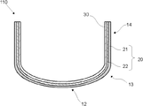
- FIG. 1 shows a schematic sectional view of an example (first embodiment) of the quartz glass crucible according to the present invention.
- the quartz glass crucible 110 of the present invention includes a bottom portion 12, a curved portion 13, and a straight body portion.
- the straight body portion 14 refers to a substantially cylindrical portion of the crucible shape.
- the area between the straight body part 14 and the bottom part 12 is called a curved part 13.
- Crucible bottom 12 can be defined, for example, as a portion having a diameter of about two-thirds or less of the outer diameter of the crucible.
- the height of the straight body portion 14 can be defined, for example, as the upper third of the crucible height, but varies depending on the shape of the crucible.
- the quartz glass crucible 110 has an outer layer 20 made of opaque quartz glass containing bubbles and an inner layer 30 made of transparent quartz glass.
- the inner layer 30 is a portion that looks transparent because it does not substantially contain air bubbles.
- the outer layer 20 is composed of a plurality of layers at least in a part of the straight body portion 14.
- FIG. 1 shows an example in which the entire outer layer 20 (all of the bottom portion 12, the curved portion 13, and the straight body portion 14) is composed of two layers, and the outer layer 20 has a devitrification easy layer 21 and a low devitrification layer 22, which will be described later. ing.
- Quartz glass crucible 110 of the present invention further, among the plurality of layers constituting the outer layer 20, at least one layer, the quartz glass crucible 110 devitrification number spots when heated for 24 hours at 1600 ° C. is 50 / cm 3
- the devitrification easy layer 21 having a number of 70 or more / cm 3 or less, of the plurality of layers, a layer located inside the devitrification easy layer 21 in the thickness direction of the quartz glass crucible 110 is the quartz glass crucible 110.
- a low devitrification layer 22 having a number of devitrification spots of 2 / cm 3 or less when heated at 1600 ° C. for 24 hours.
- the number of devitrification spots can be measured by preparing a sample from a quartz glass crucible after the heat treatment and observing the sample under an optical microscope.
- the devitrification easy layer 21 has at least a part of the straight body portion 14 of the quartz glass crucible 110, preferably the height of the straight body portion. When it is set to 100%, it is preferable that at least 50% or more thereof be present. However, the devitrification easy layer 21 may be present at the entire height of the straight body portion 14, and as shown in FIG. 1, is present at all of the straight body portion 14, the curved portion 13, and the bottom portion 12. You may. It is preferable that the devitrification easy layer 21 has its upper end located at a position higher than the melt surface of the straight body portion 14 when the silicon melt is held in the quartz glass crucible 110. Further, it is preferable that the lower end of the devitrification easy layer 21 is set to the curved portion 13 beyond the straight body portion 14. By setting such a position, the strength of the quartz glass crucible 110 during heating can be more effectively maintained.
- the low devitrification layer 22 is a layer located inside the devitrification easy layer 21 in the thickness direction of the quartz glass crucible 110 as described above.
- the low devitrification layer 22 is a layer having a devitrification spot number of 2 / cm 3 or less when the quartz glass crucible 110 is heated at 1600 ° C. for 24 hours.
- the low devitrification layer 22 is preferably located adjacent to the inside of the devitrification easy layer 21 in the thickness direction of the quartz glass crucible 110 as shown in FIG.
- Other layers for example, a medium-devitrification layer described later, may exist between the permeable layer 22 and the devitrification easy layer 21. In either case, the effect of suppressing the progress of devitrification inward can be obtained.
- the outer layer 20 of the quartz glass crucible of the present invention may have a layer other than the devitrification easy layer 21 and the low devitrification layer 22.
- the outer layer composed of a plurality of layers preferably has a middle devitrification layer as a layer other than the easily devitrified layer and the low devitrification layer.
- the medium devitrification layer is a layer in which the number of devitrification spots when the quartz glass crucible is heated at 1600 ° C. for 24 hours is more than 2 / cm 3 and not more than 10 / cm 3 .
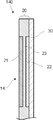
- the quartz glass crucible 120 has a devitrification easy layer 21 and a low devitrification layer 22 in a part of the straight body portion 14 of the outer layer 20.
- the low devitrification layer 22 is adjacent to the easily devitrified layer 21 and exists at a position from the easily devitrified layer 21 to the inner layer 30. Further, in the portion of the outer layer 20 in which the devitrification easy layer 21 and the low devitrification layer 22 do not exist, the middle devitrification layer 23 exists.
- the quartz glass crucible 120 having such a configuration, when the quartz glass crucible 120 is heated, for example, when pulling a silicon single crystal, the devitrification easy layer 21 is devitrified, and the crucible strength can be increased. At the same time, the presence of the low devitrification layer 22 can suppress the propagation of devitrification generated in the devitrification easy layer 21 and prevent the quartz glass crucible 120 from being cracked or damaged. Can be.
- the quartz glass crucible 130 has an easily devitrified layer 21 and a low-devitrification layer 22 in a part of the straight body portion 14 of the outer layer 20. Further, a middle devitrification layer 23 is present adjacent to the low devitrification layer 22 also in a portion of the straight body portion 14 where the devitrification easy layer 21 and the low devitrification layer 22 are present. In the quartz glass crucible 130, the middle devitrification layer 23 also exists in a portion where the devitrification easy layer 21 and the low devitrification layer 22 do not exist.
- the quartz glass crucible 130 having such a configuration increases the crucible strength by promoting the devitrification of the crucible wall by the devitrification easy layer 21, while suppressing the progress and propagation of devitrification by the low devitrification layer 22. .
- the low devitrification layer 22 itself does not easily cause devitrification, the low devitrification layer 22 itself has low strength at the time of heating. Therefore, the presence of the middle devitrification layer 23 makes it possible to supplement the strength of the crucible and enhance the deformation resistance of the entire quartz glass crucible.
- the outer layer 20 of the quartz glass crucible of the present invention may have another layer in addition to the devitrification easy layer 21, the low devitrification layer 22, and the middle devitrification layer 23.
- the devitrification easy layer 21 and the low devitrification layer 22 may be each one layer in the thickness direction of the quartz glass crucible, but may be a plurality of layers.
- the middle devitrification layer 23 or another layer is present in the outer layer 20, only one layer may be provided or a plurality of layers may be provided.
- the quartz glass crucible 140 includes the devitrification easy layer 21 and the low devitrification layer in a part of the straight body portion 14 of the outer layer 20. It has a layer 22. However, in the fourth embodiment, a middle devitrification layer 23 is provided between the easily devitrified layer 21 and the low devitrification layer 22. Also in this case, the strength of the quartz glass crucible 140 can be increased by causing devitrification in the devitrification easy layer 21 by heating.
- the outermost layer of the plurality of outer layers 20 may be the devitrification easy layer 21.
- the outermost layer of the plurality of layers constituting the outer layer 20 the devitrification easy layer 21.
- the outermost layer is easily devitrified, the crucible strength is easily maintained, and the propagation of devitrification in the direction of the inner layer 30. Can be easily suppressed.
- the outer layer 20 is preferably made of natural quartz glass
- the inner layer 30 is preferably made of synthetic quartz glass.
- the inner layer 30 By forming the inner layer 30 of synthetic quartz glass, it is possible to reduce impurity contamination of contents (silicon melt) held in the quartz glass crucibles 110, 120, 130, and 140.
- the outer layer 20 is made of natural quartz glass, the devitrification density of the outer layer 20 can be easily adjusted appropriately, the strength can be maintained, and the cost can be reduced.
- the thickness of the devitrification easy layer 21 is preferably 5% or more of the thickness of the quartz glass crucibles 110, 120, 130, and 140.
- the thickness of the devitrification easy layer 21 is more preferably 30% or less of the thickness of the quartz glass crucibles 110, 120, 130, 140. If the devitrification easy layer has a thickness of 30% or less of the thickness of the quartz glass crucible, it is possible to suppress excessive devitrification.
- the thickness of the low devitrification layer 22 is preferably 20% or more and 70% or less of the thickness of the quartz glass crucibles 110, 120, 130, and 140. Thereby, propagation of the devitrification caused by the devitrification easy layer 21 can be more effectively suppressed, and the strength of the crucible can be sufficiently secured.
- the thickness of the low-devitrification layer 22 is more preferably 20% to 60% of the thickness of the quartz glass crucibles 110, 120, 130, 140.
- the thickness of the inner layer 30 is preferably 5% or more of the thickness of the quartz glass crucibles 110, 120, 130, 140.
- the thickness of the inner layer 30 is more preferably 10% or more of the thickness of the quartz glass crucibles 110, 120, 130, 140.
- the thickness of the medium devitrification layer 23 is preferably 10% or more of the thickness of the quartz glass crucible 130. Thereby, the strength of the quartz glass crucible 130 can be more effectively secured.
- each layer constituting the quartz glass crucible can be measured by, for example, cross-sectional observation. That is, the thickness of each layer may be measured from the cross-sectional direction by breaking the quartz glass crucible. In that case, the boundary of each layer can also be confirmed using a polarizing plate. In addition, if a bubble density distribution is given to each layer according to a difference in rotational speed of the mold when the quartz glass crucible is manufactured, the thickness of each layer can be easily measured. In addition, the thickness of each layer can be confirmed by performing profile analysis for each impurity layer by ICP measurement.
- the quartz glass crucibles 110 and 130 of the present invention shown in FIGS. 1 and 3 can be manufactured using the raw material powder for the plurality of layers constituting the outer layer 20 and the raw material powder for the inner layer 30.
- a raw material powder molded body is formed in a rotary mold so as to correspond to each layer of the quartz glass crucibles 110 and 130 to be manufactured, and this is heated from the inside by arc discharge or the like.
- the quartz glass crucibles 110 and 130 can be manufactured.
- a portion corresponding to the outer layer 20 is molded in a rotary mold as a raw material powder molded body, and the inner layer 30 is heated and melted from the inside of the outer layer raw material powder molded body by arc discharge, and simultaneously in the high-temperature atmosphere.
- the inner layer 30 may be formed on the inner surface of the outer layer 20 by supplying a raw material powder such as a synthetic quartz glass powder.
- the raw material powder of the devitrification easy layer 21 is prepared by preparing a raw material powder (raw material powder before performing a doping process) and doping a crystallization accelerator (Al, Ba, or the like) into the raw material powder. can do.
- a crystallization accelerator Al, Ba, or the like
- the devitrification easy layer 21 is defined by the number of devitrification spots under predetermined conditions (heating at 1600 ° C. for 24 hours). This is different from the case where the degree of devitrification is conventionally defined by the impurity concentration of an impurity element such as Al or Ba.
- the concentration of the crystallization accelerator in the raw material powder of the easily devitrified layer 21 is preferably set according to the number of devitrified spots when the easily devitrified layer 21 is formed. That is, after forming the devitrification easy layer 21 of the quartz glass crucibles 110 and 130 from the raw material powder, the number of devitrification spots when heated at 1600 ° C. for 24 hours becomes 50 / cm 3 or more and 70 / cm 3 or less.
- the impurity concentration is adjusted by, for example, doping the raw material powder of the devitrification easy layer 21 with a crystallization accelerator, and the sample prepared using this raw material is subjected to the above-described heat treatment to obtain the desired devitrification. It is sufficient to investigate whether or not the number of spots will be obtained, and to select raw material powder to be used based on the result. A raw material powder capable of obtaining the above devitrification spot number without adjusting the impurity concentration can also be used.
- the raw material powder of the low-devitrification layer 22 has a devitrification spot number of 2 / cm 3 or less when heated at 1600 ° C. for 24 hours after forming the low-devitrification layer 22 of the quartz glass crucibles 110 and 130 from the raw material powder.
- the raw material powder is selected and used.
- the raw material powder of the middle devitrification layer 23 is formed at 1600 ° C. after forming the middle devitrification layer 23 of the quartz glass crucible 130 from the raw material powder.
- the raw material powder is selected and used so that the number of devitrification spots when heated for 24 hours is more than 2 / cm 3 and 10 / cm 3 or less.
- the inner layer 30 of the quartz glass crucibles 110 and 130 it is preferable to use synthetic quartz powder.
- the inner layer 30 can be a synthetic quartz glass layer.
- Each of the above-mentioned raw material powders is placed in a rotary mold so as to correspond to each layer constituting the outer layer 20 of the quartz glass crucibles 110 and 130 to be manufactured, and is heated.
- a quartz glass piece to be a sample is prepared from each raw material powder and a heating experiment (1600) C. for 24 hours), but it is preferable to actually prepare a quartz glass crucible, heat it at 1600 ° C. for 24 hours, take out samples from each layer, and measure. This is because the number of devitrified spots can be defined according to the conditions when the quartz glass crucible was actually manufactured.
- the number of devitrification spots of each layer measured by producing a quartz glass crucible can be considered to be the same for each layer formed from the raw material powder of the same lot.
- a quartz glass crucible 130 as shown in FIG. 3 was produced as follows.
- a raw material powder (raw material powder A) for forming the easily devitrified layer 21 a raw material powder made of Al-doped natural quartz powder having a particle size of 50 to 500 ⁇ m was prepared.
- the raw material powder (base raw material powder) before doping with Al was a raw material powder having 13 devitrification spots / cm 3 when heated at 1600 ° C. for 24 hours after being made of quartz glass.
- By doping Al into the base material powder so that devitrification number spots when the Al-doped raw material powder was heated for 24 hours at 1600 ° C.
- the quartz glass is 50 / cm 3 or more 70 / cm 3
- the dope amount was adjusted.
- a raw material powder (raw material powder B) made of natural quartz powder having a particle diameter of 50 to 500 ⁇ m and having a devitrification spot number of 1 / cm 3 was prepared.
- a raw material powder (raw material powder C) made of natural quartz powder and having a particle diameter of 50 to 500 ⁇ m with a devitrification spot number of 8 / cm 3 was prepared.
- the raw material powder A was supplied to the rotating inner cylindrical body having an inner diameter of 830 mm to form a powder layer A having a thickness of 10 mm (powder layer serving as the easily devitrified layer 21).
- the powder layer A was molded such that the devitrification-easy layer 21 of the quartz glass crucible 130 to be manufactured was located at a part of the straight body portion 14 as shown in FIG.
- the raw material powder B was supplied to the straight body in the mold, and a powder layer B (powder layer serving as the low devitrification layer 22) having a thickness of 10 mm was formed inside the powder layer A.
- the raw material powder C was supplied to the straight body portion, the curved portion, and the bottom portion in the mold, and the remaining powder layer C (the powder layer serving as the middle devitrification layer 23) required for molding was formed.
- the middle devitrification layer 23 of the quartz glass crucible 130 to be manufactured is located inside the low devitrification layer 22 and above and below the devitrification easy layer 21 and the low devitrification layer 22 as shown in FIG. Powder layer C was formed as described above.
- the molded body is heated and melted from the inside of the molded body by arc discharge, and at the same time, synthetic quartz glass powder is supplied into the high-temperature atmosphere at a rate of 100 to 200 g / min. Over a thickness of 1-3 mm. After the melting was completed, the upper end of the cooled quartz glass crucible having a diameter of 805 to 815 mm was cut so as to have a height of 500 mm, thereby producing a quartz glass crucible 130.
- the straight body of the quartz glass crucible 130 having the thickness of the devitrification easy layer 21 was measured.
- the ratio of 14 to the wall thickness was about 15%.
- the ratio of the thickness of the low-devitrification layer 22 to the thickness of the straight body portion 14 of the quartz glass crucible 130 was about 40%.
- the number of devitrification spots of the easily devitrified layer 21, the low-devitrification layer 22 and the middle devitrification layer 23 was measured.
- the number of devitrification spots, devitrification easily layer 21 is 60 / cm 3
- low devitrified layer 22 is one / cm 3
- Chushitsu Toruso 23 was 8 / cm 3.
- a silicon single crystal was pulled up using the quartz glass crucible 130 manufactured in the same manner as above, and the operation result was evaluated.
- the deformation resistance and the devitrification state were evaluated.
- the evaluation criteria are as follows: Regarding the deformation resistance, if the deformation that affects the operation occurs, it is “poor”; if there is a slight deformation that does not affect the operation, it is “good”. The case where it was not possible was regarded as “particularly good”.
- the thickness of the devitrification layer after operation was 60% or more of the thickness of the quartz glass crucible 130, it was determined to be “defective”. . When this thickness was less than 60% of the thickness of the quartz glass crucible 130, it was determined to be “good”. When this thickness was less than 50% of the thickness of the quartz glass crucible 130, it was determined to be "particularly good.”
- Example 1 no problem was found in the operation result, and the result was good.
- Table 2 shows the number of layers (sub-layers) constituting the outer layer, the type of layer defined based on the number of devitrified spots of the plurality of layers constituting the outer layer, the number of devitrified spots, and the type of the inner layer in Example 1. Indicated. Table 2 also shows the ratio of the thickness of the easily devitrified layer 21 and the low devitrification layer 22 to the thickness of the crucible in the quartz glass crucible before operation (hereinafter, also simply referred to as “layer thickness ratio”). Indicated. Table 2 shows the evaluation of the deformation resistance and the devitrification state as the evaluation of the operation results.
- Example 2 A quartz glass crucible was manufactured in the same manner as in Example 1, except that, in the outer layer, the middle devitrification layer was disposed on the outermost layer, and the easily devitrified layer and the low devitrification layer were disposed on the inner side.
- Table 2 shows the number of devitrification spots and the layer thickness ratio of the easily devitrified layer and the low devitrification layer in each layer. The operation results were evaluated in the same manner as in Example 1, and the results were as shown in Table 2.
- Example 3 A quartz glass crucible was manufactured in the same manner as in Example 1, but the layer thickness ratio of the low-devitrification layer 22 in the outer layer was set to 22%. Table 2 shows the number of devitrification spots in each layer and the layer thickness ratio of the devitrification easy layer. The operation results were evaluated in the same manner as in Example 1, and the results were as shown in Table 2.
- Example 4 A quartz glass crucible was manufactured in the same manner as in Example 1, except that the thickness ratio of the low-devitrification layer 22 in the outer layer was set to 18%. Table 2 shows the number of devitrification spots in each layer and the layer thickness ratio of the devitrification easy layer. The operation results were evaluated in the same manner as in Example 1, and the results were as shown in Table 2. The devitrification state was "good", and although the devitrification progressed from Example 1, no problem occurred in the operation.
- Example 5 A quartz glass crucible was manufactured in the same manner as in Example 1, but the thickness ratio of the devitrification easy layer 21 in the outer layer was set to 5%. Table 2 shows the number of devitrification spots and the ratio of the thickness of the low devitrification layer in each layer. The operation results were evaluated in the same manner as in Example 1, and the results were as shown in Table 2. Devitrification progressed less than in Example 1, but no problematic deformation occurred in the operation.
- Example 6 A quartz glass crucible was manufactured in the same manner as in Example 1, but the layer thickness ratio of the easily devitrified layer 21 in the outer layer was 35%. Table 2 shows the number of devitrification spots and the ratio of the thickness of the low devitrification layer in each layer. The operation results were evaluated in the same manner as in Example 1, and the results were as shown in Table 2. Although devitrification progressed from Example 1, there was no problem in operation.
- Example 7 A quartz glass crucible was manufactured in the same manner as in Example 1. However, as a raw material powder for forming a layer corresponding to the middle devitrification layer 23 in Example 1, a raw material in which devitrification is more likely to progress by heating after being made of quartz glass Powder was used. The number of devitrification spots in each layer and the layer thickness ratio of the easily devitrified layer / low devitrification layer are as shown in Table 2. In the layer corresponding to the middle devitrification layer 23 in Example 1, the number of devitrification spots was There were twelve. This is higher than the range of the “medium devitrification layer” in the present invention, and the devitrification proceeds more easily than in Example 1 due to heating in pulling a silicon single crystal. The operation results of the manufactured quartz glass crucible were evaluated in the same manner as in Example 1, and the results are as shown in Table 2. The devitrification state was “good”, and devitrification proceeded more than in Example 1. However, there was no problem in the operation.
- Example 8 A quartz glass crucible was manufactured in the same manner as in Example 1, except that the thickness ratio of the low-devitrification layer 22 in the outer layer was 10%. Table 2 shows the number of devitrification spots in each layer and the layer thickness ratio of the devitrification easy layer. The operation results were evaluated in the same manner as in Example 1, and the results were as shown in Table 2. The devitrification state was “good”, and devitrification proceeded more than in Example 1. It is considered that the low devitrification layer 22 is thin. However, there was no problem in the operation.
- Example 9 A quartz glass crucible was manufactured in the same manner as in Example 1. However, as a raw material powder for forming a layer corresponding to the middle devitrification layer 23 in Example 1, a raw material in which devitrification is more likely to progress by heating after being made of quartz glass Powder was used. The number of devitrification spots in each layer and the layer thickness ratio of the easily devitrified layer / low devitrification layer are as shown in Table 2. In the layer corresponding to the middle devitrification layer 23 in Example 1, the number of devitrification spots was There were fifteen. This is higher than the range of the “medium devitrification layer” in the present invention, and the devitrification proceeds more easily than in Example 1 due to heating in pulling a silicon single crystal. The operation results of the manufactured quartz glass crucible were evaluated in the same manner as in Example 1, and the results are as shown in Table 2. The devitrification state was "good", and although the devitrification progressed from Example 1, no problem occurred in the operation.
- Example 10 The quartz glass crucible 120 shown in FIG. 2 was produced.
- the raw material powder (raw material powder A) for forming the easily devitrified layer 21 used in Example 1
- the method of producing the raw material powder molded body is as follows. First, the raw material powder A was supplied to a rotating inner cylindrical body having an inner diameter of 830 mm, and a powder layer A having a thickness of 10 mm (a powder layer to be the devitrification easy layer 21) was formed. At this time, the powder layer A was molded such that the devitrification-easy layer 21 of the quartz glass crucible 120 to be manufactured was located at a part of the straight body portion 14 as shown in FIG. Next, the raw material powder B was supplied to the straight body in the mold, and a powder layer B having a thickness of 18 mm (a powder layer serving as the low devitrification layer 22) was formed inside the powder layer A.
- the raw material powder C is supplied to a region in which the powder layers A and B have not been formed among the straight body portion, the curved portion, and the bottom portion in the mold, and the remaining powder layer C required for molding (medium devitrification) (A powder layer to be the layer 23) was molded.
- the powder layer C was molded such that the middle devitrification layer 23 of the quartz glass crucible 120 to be manufactured was located above and below the devitrification easy layer 21 and the low devitrification layer 22, as shown in FIG. .
- the molded body is heated and melted from the inside of the molded body by arc discharge, and at the same time, synthetic quartz glass powder is supplied into the high-temperature atmosphere at a rate of 100 to 200 g / min. Over a thickness of 1-3 mm. After the melting was completed, the upper end of the cooled quartz glass crucible having a diameter of 805 to 815 mm was cut so as to have a height of 500 mm, thereby producing a quartz glass crucible 120.
- the quartz glass crucible 120 When the quartz glass crucible 120 was broken and the thicknesses of the devitrification easy layer 21 and the low devitrification layer 22 were measured from the cross-sectional direction, the ratio of the quartz glass crucible 120 to the thickness of the straight body portion 14 was devitrified.
- the easy layer was about 15%, and the low devitrification layer was about 70%.
- the number of devitrification spots of the easily devitrified layer 21, the low-devitrification layer 22, and the middle devitrification layer 23 was measured.
- the number of devitrification spots, devitrification easily layer 21 is 60 / cm 3
- low devitrified layer 22 was 1 / cm 3.
- the number of devitrification spots was 7 / cm 3 in the middle devitrification layer 23 located above and below the devitrification easy layer 21 and the low devitrification layer 22.
- Example 11 In the outer layer, a quartz glass crucible having a structure in which a devitrification easy layer was sandwiched by a low devitrification layer was produced.
- the raw material powder (raw material powder A) for forming the easily devitrified layer 21 used in Example 1, the raw material powder (raw material powder B) for forming the low devitrified layer 22, and the formation of the inner layer 30 are used.
- Raw material powder was used.
- the method of producing the raw material powder molded body is as follows. First, the raw material powder B was supplied to the straight body in the mold, and the powder layer B (the powder layer to be a low devitrification layer) was formed. Next, the raw material powder A was formed into a powder layer A (powder layer serving as an easily devitrified layer) on a straight body in the mold. Further, the raw material powder B was supplied to a straight body in the mold, and a second powder layer B (a powder layer to be a low devitrification layer) was formed.
- the raw material powder C is supplied to a region in which the powder layers A and B have not been formed among the straight body portion, the curved portion, and the bottom portion in the mold, and the remaining powder layer C (middle devitrification) required for molding is supplied. (A powder layer to be a layer) was molded.
- the molded body is heated and melted from the inside of the molded body by arc discharge, and at the same time, synthetic quartz glass powder is supplied into the high-temperature atmosphere at a rate of 100 to 200 g / min. Over a thickness of 1-3 mm. After the melting was completed, the upper end of the cooled quartz glass crucible having a diameter of 805 to 815 mm was cut so as to have a height of 500 mm, thereby producing a quartz glass crucible.
- the quartz glass crucible was manufactured by changing the order of each layer in the outer layer 20 from the quartz glass crucible 130 of Example 1. That is, a quartz glass crucible was manufactured as a configuration of a middle devitrification layer, a low devitrification layer, and a devitrification easy layer from the outer layer. In this case, since the devitrification easy layer was in contact with the inner layer, devitrification also progressed too much in the inner layer, and all the evaluations of the operation results were “poor”.
- Example 2 A quartz glass crucible was manufactured basically in the same manner as in Example 1. However, in the outer layer, the Al doping concentration was reduced in the raw material powder of the layer corresponding to the devitrification easy layer 21 in FIG. / Cm 3 . Table 2 shows the number of devitrification spots and the layer thickness ratio of the easily devitrified layer and the low devitrification layer in each layer. The operation results were evaluated in the same manner as in Example 1, and the results were as shown in Table 2. Deformation resistance was "poor", which affected the operation results. It is considered that the devitrification in the outer layer was insufficient.
- Example 3 A quartz glass crucible was manufactured basically in the same manner as in Example 1. However, in the outer layer, the Al powder concentration was increased in the raw material powder of the layer corresponding to the devitrification easy layer 21 in FIG. / Cm 3 .
- Table 2 shows the number of devitrification spots and the layer thickness ratio of the easily devitrified layer and the low devitrification layer in each layer. The operation results were evaluated in the same manner as in Example 1, and the results were as shown in Table 2. The devitrification state was "poor" because the layer corresponding to the devitrification easy layer caused excessive devitrification.
- Comparative Example 4 A quartz glass crucible was manufactured in the same manner as in Comparative Example 2; however, in the outer layer, a middle devitrification layer was used as a raw material powder for a layer (the second layer from the outermost layer) corresponding to the low devitrification layer 22 in FIG. Such raw material powder (provided that the number of devitrification spots is smaller than that of the third layer from the outermost layer) was used. Table 2 shows the number of devitrification spots and the layer thickness ratio of the easily devitrified layer and the low devitrification layer in each layer. The operation results were evaluated in the same manner as in Example 1, and the results were as shown in Table 2. Deformation resistance was "poor", which affected the operation results. It is considered that the devitrification in the outer layer was insufficient. The devitrification state was “good”, and devitrification proceeded more than in Example 1.
- Comparative Example 5 A quartz glass crucible was manufactured in the same manner as in Comparative Example 3, but in the outer layer, a middle devitrification layer was used as a raw material powder of a layer (the second layer from the outermost layer) corresponding to the low devitrification layer 22 in FIG. Such raw material powder (provided that the number of devitrification spots is smaller than that of the third layer from the outermost layer) was used. Table 2 shows the number of devitrification spots in each layer and the layer thickness ratio of the devitrification easy layer. The operation results were evaluated in the same manner as in Example 1, and the results were as shown in Table 2. The devitrification state was "poor" because the layer corresponding to the devitrification easy layer caused excessive devitrification.
- FIG. 5 A quartz glass crucible 200 having a configuration as shown in FIG. 5 was manufactured.
- the outer layer 220 is entirely composed of a middle devitrification layer 223, and an inner layer 230 is formed on the outer layer 220.
- the raw material powder the raw material powder for forming the middle devitrification layer 23 and the raw material powder for forming the inner layer 30 used in the quartz glass crucible 130 of Example 1 were used.
- the number of devitrification spots in the outer layer 220 was as shown in Table 2.
- the operation results were evaluated in the same manner as in Example 1, and the results were as shown in Table 2.
- Deformation resistance was "poor", which affected the operation results. It is considered that the devitrification in the outer layer was insufficient.
- FIG. 6 A quartz glass crucible 300 having a configuration as shown in FIG. 6 was manufactured.
- an outer layer 220 is composed of an easily devitrified layer 221 and a middle devitrified layer 223, and an inner layer 230 is formed on the outer layer 220. It does not have a low devitrification layer.
- the raw material powder the raw material powder for forming the devitrification easy layer 21 and the raw material powder for forming the middle devitrification layer 23 and the raw material powder for forming the inner layer 30 used in the quartz glass crucible 130 of Example 1 are used. Using.
- the number of devitrification spots in each layer constituting the outer layer was as shown in Table 2.
- the operation results were evaluated in the same manner as in Example 1, and the results were as shown in Table 2.
- the devitrification state was "poor", which affected the operation results. This is because devitrification has progressed too much in the outer layer.
- the present invention is not limited to the above embodiment.
- the above embodiment is merely an example, and any embodiment having substantially the same configuration as the technical idea described in the claims of the present invention and exerting the same function and effect will be described. It is included in the technical scope of the invention.
Landscapes
- Chemical & Material Sciences (AREA)
- Engineering & Computer Science (AREA)
- Materials Engineering (AREA)
- Organic Chemistry (AREA)
- Crystallography & Structural Chemistry (AREA)
- Metallurgy (AREA)
- Manufacturing & Machinery (AREA)
- Crystals, And After-Treatments Of Crystals (AREA)
- Glass Melting And Manufacturing (AREA)
- Glass Compositions (AREA)
Abstract
本発明は、底部、湾曲部及び直胴部からなる石英ガラスるつぼであって、気泡を含有する不透明石英ガラスからなる外層と、透明石英ガラスからなる内層とを有し、前記外層は、少なくとも前記直胴部の一部において、複数層から構成されており、前記複数層のうち、少なくとも1層が、前記石英ガラスるつぼを1600℃で24時間加熱した際の失透斑点数が50個/cm3以上70個/cm3以下である失透容易層であり、前記複数層のうち、前記石英ガラスるつぼの肉厚方向において、前記失透容易層の内側に位置する層が、前記石英ガラスるつぼを1600℃で24時間加熱した際の失透斑点数が2個/cm3以下である低失透層である石英ガラスるつぼである。これにより、加熱による変形を抑制することができるとともに失透の進みすぎを抑制することができる石英ガラスるつぼが提供される。
Description
本発明は、石英ガラスるつぼに関する。
従来、単結晶半導体材料のような単結晶物質の製造には、いわゆるチョクラルスキー法と呼ばれる方法が広く採用されている。この方法は多結晶シリコンを容器内で溶融させ、この溶融浴(融液)内に種結晶の端部を浸けて回転させながら引き上げるものである。この方法では、種結晶の下に同一の結晶方位を持つ単結晶が成長する。単結晶シリコンを引き上げる場合、この単結晶引き上げ容器には石英ガラスるつぼが一般的に使用されている。この石英ガラスるつぼは気泡を含有する不透明石英ガラスからなる外層と、実質的に気泡を含有しない透明石英ガラスからなる内層とを有している。
近年、シリコン単結晶引上げの操業時間の長時間化に伴い、石英ガラスるつぼの多機能化が求められている。具体的には、長時間の加熱による石英ガラスるつぼが変形するという変形問題が発生しているが、その対策として結晶化促進層を設けることで変形問題を解消することができる。例えば、特許文献1には、石英ガラスるつぼの外層に結晶化促進剤添加シリカガラスからなる層を設けることが記載されている。また、特許文献2には、ルツボの外層がAl添加石英層、中間層が天然石英層または高純度合成石英層、内層が透明高純度合成石英層からなる3層構造である石英ガラスルツボが記載されている。特許文献3には、るつぼ用途に使用する原料を加熱して失透評価するという内容が記載されている。
上記のように、長時間の加熱による石英ガラスるつぼの変形問題に対しては、るつぼ外層に結晶化促進層を設けることで解消することができる。しかしながら、結晶化が過剰に進むと、失透現象が進みすぎたり、失透現象がるつぼの肉厚方向に進行していくという失透問題が派生するため、結晶化抑制の対応が必要である。失透現象が進みすぎると、るつぼに亀裂が生じる等の破損等の問題が発生する。これらの問題に関し、変形問題に対しては結晶化促進を、失透問題に対しては結晶化抑制を、1つの石英ガラスるつぼ内で相反する対策を施すことが必要である。
また、従来、石英ガラスるつぼを加熱した際の失透のし易さをシリカ以外のAl、Ba等の不純物元素の不純物濃度で規定していた。しかしながら、同じ不純物濃度を有するシリカガラスを同じ加熱条件で加熱した場合であっても、失透の状況が異なる場合があることが本発明者の検討により明らかとなった。例えば、特許文献1には、上記のように石英ガラスるつぼの外層に結晶化促進剤を添加することが記載されているが、失透のし易さについて結晶化促進剤(Al、Ba、Ca、K)の濃度で規定されている。また、特許文献2も、るつぼ各層におけるAl濃度により、るつぼ各層の結晶化の程度を制御することが記載されている。しかしながら、これらの不純物濃度と失透の度合いとは、必ずしも高い相関関係は得られない。
本発明は、上記した事情に鑑みなされたもので、加熱による変形を抑制することができるとともに失透の進みすぎを抑制することができる石英ガラスるつぼを提供することを目的とする。
本発明は、上記課題を解決するためになされたもので、底部、湾曲部及び直胴部からなる石英ガラスるつぼであって、気泡を含有する不透明石英ガラスからなる外層と、透明石英ガラスからなる内層とを有し、前記外層は、少なくとも前記直胴部の一部において、複数層から構成されており、前記複数層のうち、少なくとも1層が、前記石英ガラスるつぼを1600℃で24時間加熱した際の失透斑点数が50個/cm3以上70個/cm3以下である失透容易層であり、前記複数層のうち、前記石英ガラスるつぼの肉厚方向において、前記失透容易層の内側に位置する層が、前記石英ガラスるつぼを1600℃で24時間加熱した際の失透斑点数が2個/cm3以下である低失透層であることを特徴とする石英ガラスるつぼを提供する。
このような石英ガラスるつぼは、外層を構成する複数層において失透容易層を有することにより、加熱時に容易に失透する層とすることができる。これにより、加熱時のるつぼの強度を確保することができる。それとともに、同時に、外層を構成する複数層において、失透容易層より内側に低失透層を有することにより、失透容易層の存在による失透の進みすぎを防止することができる。これらの層の存在により、るつぼの変形の抑制と、失透の進みすぎの抑制を両立することができる。また、これらの各層は、失透斑点数により定義することにより、確実に、失透の状態を制御することができる。
この場合、前記複数層からなる外層は、前記失透容易層及び前記低失透層以外の層として、前記石英ガラスるつぼを1600℃で24時間加熱した際の失透斑点数が2個/cm3を超え10個/cm3以下である中失透層を有するものであることが好ましい。
このような外層を構成する複数層において中失透層を有する石英ガラスるつぼであれば、中失透層による適度な失透により、るつぼの強度をより高くしやすくすることができる。
また、前記外層の前記複数層のうち、最外層が前記失透容易層であることが好ましい。
このように、外層を構成する複数層のうち最外層を失透容易層とすることにより、るつぼ最外層が失透しやすくなり、るつぼ強度を高く保ちやすくなるとともに、内層方向への失透の伝搬を抑制しやすくできる。
また、前記外層は天然石英ガラスからなり、前記内層は合成石英ガラスからなることが好ましい。
このように、るつぼ内層を合成石英ガラスからなるものとすることにより、るつぼに保持する内容物に対する不純物汚染を低減することができる。それとともに、るつぼ外層を天然石英ガラスからなるものとすることにより、外層における失透密度を適度に調整して強度を維持できるとともに、低コストとすることができる。
また、前記失透容易層の厚さが、前記石英ガラスるつぼの肉厚の5%以上であり、前記低失透層の厚さが、前記石英ガラスるつぼの肉厚の20%以上70%以下であり、前記内層の厚さが、前記石英ガラスるつぼの肉厚の5%以上であることが好ましい。
このように、失透容易層の厚さを石英ガラスるつぼの肉厚の5%以上とすれば、失透させる部分の確保をより十分に行うことができる。また、低失透層の厚さを石英ガラスるつぼの肉厚の20%以上とすることにより、失透容易層により生じた失透の伝搬をより効果的に抑制することができる。また、低失透層の厚さを石英ガラスるつぼの肉厚の70%以下とすることにより、るつぼ強度をより確実に確保することができる。また、内層の厚さを石英ガラスるつぼの肉厚の5%以上とすることにより、るつぼの内容物を適切に保持できるとともに、内容物への不純物汚染をより効果的に抑制することができる。
本発明の石英ガラスるつぼは、外層を構成する複数層において、失透斑点数により定義された失透容易層とその内側に低失透層を有することにより、るつぼの変形の抑制と、失透の進みすぎの抑制を両立することができる。
従来、石英ガラスるつぼにおいて、失透を促進させるための結晶化促進層には、Al、Baなどの金属不純物を添加するのが一般的であった。また、特許文献1、特許文献2に記載されているように、結晶化促進層は、その不純物濃度を規定することが一般的であった。しかしながら、本発明者の検討によると、ベースとなる原料粉として異なる原料粉(例えば、生産地や生産者等が異なる原料粉)を用いた場合、不純物濃度が一定であっても、失透の発生状態が異なる場合があることが判明した。不純物が添加された石英原料粉をガラス化し、その石英ガラスを加熱すると「失透」と呼ばれる現象が斑点状に発生する。図7には、失透斑点の写真を示した。
例えば、原料粉として、異なる原料粉として石英粉1~3を用いた場合に、結晶化促進不純物としてAlを各石英粉に添加して、添加後のAl濃度を50質量ppmとして一定にする。しかしながら、これらの結晶化促進剤を添加した原料粉を、同じ加熱条件で加熱しても、発生する失透斑点数(失透斑点の個数密度)が異なることが判明した。これを表1にまとめた。

このように、原料粉によっては、結晶化促進剤の濃度が高くとも結晶化レベルが低い原料粉等があることが判明した。失透によりるつぼの強度を高めようとするときに、結晶化促進るつぼで重要なのは促進剤の濃度ではなく、結果としての結晶(失透斑点)の発生数である。そのため、本発明では、失透容易層及び低失透層を失透斑点数で定義することを見出した。これにより、従来よりも確実に石英ガラスるつぼの加熱時におけるるつぼ各層の失透状態を制御することができる。
上記のように、結晶化促進不純物濃度が同じでもベースとなる原料粉によって失透斑点数が異なるのは、Al、Ba等の結晶化促進不純物元素ではないその他の要因が影響していると考えられるが、詳細な理由は不明である。しかしながら、いずれにしても、石英ガラスとした後の加熱時の失透斑点数によって規定すれば、石英ガラスるつぼにおける強度の確保や失透の進みすぎの抑制の効果を得るために必要な構成を直接的に規定することができる。そして、失透斑点数は、例えば1600℃、24時間の熱処理をサンプルに施せば、簡単に実験的に確認することができる。
また、本発明者は、石英ガラスるつぼの外層において、るつぼの変形・座屈を防止するための失透容易層(結晶化促進層)と、失透容易層(結晶化促進層)の失透を必要以上に進行させないための低失透層を内側に適切に配置することにより、るつぼの変形の抑制と、失透の進みすぎの抑制を両立することができることを見出し、本発明を完成させた。
以下、図面を参照し、本発明をより具体的に説明する。各図において、類似の構成要素は同一の符号を付して説明する。
(第1の実施態様)
図1に、本発明に係る石英ガラスるつぼの一例(第1の実施態様)の概略断面図を示す。図1に示したように、本発明の石英ガラスるつぼ110は、底部12、湾曲部13、及び直胴部14からなる。直胴部14はるつぼ形状のうち略円筒形の部分を指す。直胴部14と底部12の間の領域を湾曲部13と称する。るつぼの底部12は、例えば、るつぼの外径の約3分の2以下の直径を有する部分と定義することができる。直胴部14の高さは、例えば、るつぼの高さのうち上部4分の3の部分と定義することもできるが、るつぼの形状により様々である。
図1に、本発明に係る石英ガラスるつぼの一例(第1の実施態様)の概略断面図を示す。図1に示したように、本発明の石英ガラスるつぼ110は、底部12、湾曲部13、及び直胴部14からなる。直胴部14はるつぼ形状のうち略円筒形の部分を指す。直胴部14と底部12の間の領域を湾曲部13と称する。るつぼの底部12は、例えば、るつぼの外径の約3分の2以下の直径を有する部分と定義することができる。直胴部14の高さは、例えば、るつぼの高さのうち上部4分の3の部分と定義することもできるが、るつぼの形状により様々である。
また、石英ガラスるつぼ110は、気泡を含有する不透明石英ガラスからなる外層20と、透明石英ガラスからなる内層30とを有する。内層30は実質的に気泡を含有しないため、透明に見える部分である。また、本発明の石英ガラスるつぼ110は、外層20が、少なくとも直胴部14の一部において、複数層から構成されている。図1には、外層20全体(底部12、湾曲部13及び直胴部14の全て)が2層からなり、外層20が後述の失透容易層21及び低失透層22を有する例を示している。本発明の石英ガラスるつぼ110は、さらに、外層20を構成する複数層のうち、少なくとも1層が、石英ガラスるつぼ110を1600℃で24時間加熱した際の失透斑点数が50個/cm3以上70個/cm3以下である失透容易層21であり、その複数層のうち、石英ガラスるつぼ110の肉厚方向において、失透容易層21の内側に位置する層が、石英ガラスるつぼ110を1600℃で24時間加熱した際の失透斑点数が2個/cm3以下である低失透層22である。
失透容易層21は、上記の通り、石英ガラスるつぼ110を1600℃で24時間加熱した際の失透斑点数が50個/cm3以上70個/cm3以下である層である。失透斑点数は、熱処理後の石英ガラスるつぼからサンプルを作製し、光学顕微鏡で拡大して観察することにより測定することができる。
石英ガラスるつぼの変形・座屈は、直胴部14において発生しやすいため、失透容易層21は、少なくとも石英ガラスるつぼ110の直胴部14の一部、好ましくは直胴部の高さを100%とした場合、少なくともその50%以上存在するのがよい。ただし、失透容易層21は、直胴部14の高さ全てに存在していてもよく、図1に示したように、直胴部14、湾曲部13、底部12の全てに存在していてもよい。失透容易層21は、その上端が、直胴部14のうち石英ガラスるつぼ110にシリコン融液を保持した際の融液面よりも高い位置まで存在することが好ましい。また、失透容易層21の下端は、直胴部14を超えて湾曲部13に設定することが好ましい。このような位置に設定することにより、石英ガラスるつぼ110の加熱時における強度をより効果的に保てるためである。
低失透層22は、上記のように、石英ガラスるつぼ110の肉厚方向において、失透容易層21の内側に位置する層である。また、低失透層22は、石英ガラスるつぼ110を1600℃で24時間加熱した際の失透斑点数が2個/cm3以下の層である。外層20において低失透層22を有することにより、失透容易層21の存在による失透の進みすぎを防止することができる。このとき、低失透層22は、図1に示しているように石英ガラスるつぼ110の肉厚方向において、失透容易層21の内側に隣接して位置していることが好ましいが、低失透層22と失透容易層21の間にその他の層、例えば後述の中失透層が存在していてもよい。いずれの態様であっても、失透の内側への進行を抑制するという効果が得られる。
また、本発明の石英ガラスるつぼの外層20は、失透容易層21及び低失透層22以外の層を有していてもよい。特に、本発明の石英ガラスるつぼでは、複数層からなる外層が、失透容易層及び低失透層以外の層として、中失透層を有するものであることが好ましい。ここでの中失透層とは、石英ガラスるつぼを1600℃で24時間加熱した際の失透斑点数が2個/cm3を超え10個/cm3以下の層である。
(第2の実施態様)
図2に示した第2の実施態様において、石英ガラスるつぼ120は、外層20のうち直胴部14の一部において、失透容易層21及び低失透層22を有している。低失透層22は、失透容易層21に隣接し、失透容易層21から内層30までの位置に存在している。さらに、外層20のうち、失透容易層21及び低失透層22が存在しない部分は、中失透層23が存在している。
図2に示した第2の実施態様において、石英ガラスるつぼ120は、外層20のうち直胴部14の一部において、失透容易層21及び低失透層22を有している。低失透層22は、失透容易層21に隣接し、失透容易層21から内層30までの位置に存在している。さらに、外層20のうち、失透容易層21及び低失透層22が存在しない部分は、中失透層23が存在している。
このような構成を有する石英ガラスるつぼ120は、シリコン単結晶引上げの際等において石英ガラスるつぼ120が加熱される際に失透容易層21に失透が生じ、るつぼ強度を高くすることができる。それとともに、低失透層22の存在により、失透容易層21に生じた失透が伝搬することを抑制することができ、石英ガラスるつぼ120に亀裂が生じることや破損することを防止することができる。
(第3の実施態様)
図3に示した第3の実施態様において、石英ガラスるつぼ130は、外層20のうち直胴部14の一部において、失透容易層21及び低失透層22を有している。さらに、直胴部14のうち失透容易層21及び低失透層22の存在する部分にも、低失透層22に隣接して中失透層23が存在している。また、石英ガラスるつぼ130では、中失透層23は失透容易層21及び低失透層22の存在しない部分にも存在している。
図3に示した第3の実施態様において、石英ガラスるつぼ130は、外層20のうち直胴部14の一部において、失透容易層21及び低失透層22を有している。さらに、直胴部14のうち失透容易層21及び低失透層22の存在する部分にも、低失透層22に隣接して中失透層23が存在している。また、石英ガラスるつぼ130では、中失透層23は失透容易層21及び低失透層22の存在しない部分にも存在している。
このような構成を有する石英ガラスるつぼ130は、失透容易層21によりるつぼ壁の失透を促進することによりるつぼ強度を高める一方で、低失透層22により失透の進行、伝搬を抑制する。ここで、低失透層22自体は失透が発生しにくいため、低失透層22自体は加熱時の強度が弱い。そこで、中失透層23の存在により、るつぼ強度を補うことができ、石英ガラスるつぼ全体の耐変形性を高めることができる。
また、本発明の石英ガラスるつぼの外層20は、失透容易層21、低失透層22、中失透層23の他にさらにその他の層を有していてもよい。また、失透容易層21、低失透層22は、石英ガラスるつぼの肉厚方向にそれぞれ1層ずつでよいが、複数層あってもよい。外層20に中失透層23又はその他の層が存在する場合も、1層ずつでよいが、複数層あってもよい。
(第4の実施態様)
図4に示した第4の実施態様においても、第3の実施態様と同様に、石英ガラスるつぼ140は、外層20のうち直胴部14の一部において、失透容易層21及び低失透層22を有している。ただし、この第4の実施態様においては、失透容易層21と低失透層22の間に中失透層23を有している。この場合も、加熱により失透容易層21で失透が発生することにより石英ガラスるつぼ140の強度を高めることができる。また、失透容易層21において多量に発生する失透が中失透層23を通じて進行しても、少なくとも低失透層22によって失透の伝搬が抑制される。これにより、石英ガラスるつぼ140全体における失透の進みすぎを抑制することができる。
図4に示した第4の実施態様においても、第3の実施態様と同様に、石英ガラスるつぼ140は、外層20のうち直胴部14の一部において、失透容易層21及び低失透層22を有している。ただし、この第4の実施態様においては、失透容易層21と低失透層22の間に中失透層23を有している。この場合も、加熱により失透容易層21で失透が発生することにより石英ガラスるつぼ140の強度を高めることができる。また、失透容易層21において多量に発生する失透が中失透層23を通じて進行しても、少なくとも低失透層22によって失透の伝搬が抑制される。これにより、石英ガラスるつぼ140全体における失透の進みすぎを抑制することができる。
図1、2、3、4に示したように、本発明の石英ガラスるつぼ110、120、130、140においては、外層20の複数層のうち、最外層が失透容易層21であることが好ましい。外層20を構成する複数層のうち最外層を失透容易層21とすることにより、最外層が失透しやすくなり、るつぼ強度を高く保ちやすくなるとともに、内層30の方向への失透の伝搬を抑制しやすくできる。
また、本発明の石英ガラスるつぼ110、120、130、140において、外層20は天然石英ガラスからなり、内層30は合成石英ガラスからなることが好ましい。内層30を合成石英ガラスからなるものとすることにより、石英ガラスるつぼ110、120、130、140に保持する内容物(シリコン融液)に対する不純物汚染を低減することができる。それとともに、外層20を天然石英ガラスからなるものとすることにより、外層20における失透密度を適度に調整しやすくなり強度を維持することができ、かつ低コストとすることができる。
また、本発明の石英ガラスるつぼ110、120、130、140において、失透容易層21の厚さは、石英ガラスるつぼ110、120、130、140の肉厚の5%以上であることが好ましい。これにより、石英ガラスるつぼ110、120、130、140において、失透させる部分の確保をより十分に行うことができる。また、この失透容易層21の厚さは、石英ガラスるつぼ110、120、130、140の肉厚の30%以下であることがさらに好ましい。石英ガラスるつぼの肉厚の30%以下の厚さの失透容易層であれば、失透が進みすぎてしまうことを抑制できる。また、低失透層22の厚さは、石英ガラスるつぼ110、120、130、140の肉厚の20%以上70%以下であることが好ましい。これにより、失透容易層21により生じた失透の伝搬をより効果的に抑制することができるとともに、るつぼの強度を十分に確保することができる。この低失透層22の厚さは、石英ガラスるつぼ110、120、130、140の肉厚の20%以上60%以下であることがさらに好ましい。また、内層30の厚さは、石英ガラスるつぼ110、120、130、140の肉厚の5%以上であることが好ましい。これにより、石英ガラスるつぼ110、120、130、140の内容物(シリコン融液)を適切に保持できるとともに、内容物への不純物汚染をより効果的に抑制することができる。内層30の厚さは、石英ガラスるつぼ110、120、130、140の肉厚の10%以上であることがさらに好ましい。
また、図3の石英ガラスるつぼ130のように中失透層23を有する場合、中失透層23の厚さは、石英ガラスるつぼ130の肉厚の10%以上であることが好ましい。これにより、石英ガラスるつぼ130の強度をより効果的に確保することができる。
石英ガラスるつぼを構成する各層の厚さは、例えば、断面観察で測定することができる。すなわち、石英ガラスるつぼを破壊して、断面方向から各層の厚さを測定すればよい。その際、偏光板を使用して各層の境界を確認することもできる。また、石英ガラスるつぼ製造時のモールドの回転速度差によって各層に気泡密度分布を付けておけば、各層の厚さを測定しやすい。その他、ICP測定により不純物層別プロファイル分析を行って各層の厚さを確認することができる。
本発明の石英ガラスるつぼの製造方法を説明する。ここでは図1の石英ガラスるつぼ110及び図3の石英ガラスるつぼ130を例として説明する。
図1、3に示した本発明の石英ガラスるつぼ110、130は、外層20を構成する複数層のための各原料粉、及び内層30のための原料粉を用いて製造することができる。例えば各原料粉(原料石英粉)を用いて、製造する石英ガラスるつぼ110、130の各層に対応するように回転モールド内に原料粉成型体を成型し、これを内部からアーク放電等により加熱すること等により、石英ガラスるつぼ110、130を製造することができる。また、外層20に相当する部分を原料粉成型体として回転モールド内に成型しておき、内層30については、アーク放電により外層用原料粉成型体の内部から加熱熔融すると同時に、その高温雰囲気中に合成石英ガラス粉等の原料粉を供給することにより、外層20の内表面上に内層30を形成してもよい。
失透容易層21の原料粉は、ベースとなる原料粉(ドープ処理を行う前の原料粉)を準備し、これに、例えば、結晶化促進剤(Al、Ba等)をドープすることにより準備することができる。ここで、本発明では、上記のように、石英ガラスるつぼ110、130を構成した際に、所定条件(1600℃で24時間加熱)における失透斑点数により失透容易層21を規定する。これは、従来のように失透のし易さをAl、Ba等の不純物元素の不純物濃度で規定していたのとは異なる。そのため、失透容易層21の原料粉における結晶化促進剤の濃度は、失透容易層21を構成した際の失透斑点数に応じて設定することが好ましい。すなわち、原料粉から石英ガラスるつぼ110、130の失透容易層21を形成した後、1600℃で24時間加熱した際の失透斑点数が50個/cm3以上70個/cm3以下となるように、予め失透容易層21の原料粉に結晶化促進剤をドープすること等により不純物濃度を調整し、この原料を用いて作製されたサンプルに上記加熱処理を行って、所望の失透斑点数となるか調査し、その結果に基づいて用いる原料粉を選別すればよい。不純物濃度を調整しなくても上記失透斑点数が得られるような原料粉を用いることもできる。
低失透層22の原料粉は、原料粉から石英ガラスるつぼ110、130の低失透層22を形成した後、1600℃で24時間加熱した際の失透斑点数が2個/cm3以下となるような原料粉を選択して用いる。
図3の石英ガラスるつぼ130のように中失透層23を有する場合、中失透層23の原料粉は、原料粉から石英ガラスるつぼ130の中失透層23を形成した後、1600℃で24時間加熱した際の失透斑点数が2個/cm3を超え10個/cm3以下となるような原料粉を選択して用いる。
石英ガラスるつぼ110、130の内層30のための原料粉としては、合成石英粉を用いることが好ましい。これにより、内層30を合成石英ガラス層とすることができる。
上記の各原料粉をそれぞれ、製造しようとする石英ガラスるつぼ110、130の外層20を構成する各層に対応するように回転モールド内に配置して加熱を行う。各原料粉から形成された石英ガラスにおいて、1600℃で24時間加熱後の失透斑点数の値を確認する際には、各原料粉からサンプルとなる石英ガラス片を作製して加熱実験(1600℃で24時間)を行って測定してもよいが、実際に石英ガラスるつぼを作製して、1600℃で24時間加熱した後に各層からサンプルを取り出して測定することが好ましい。実際に石英ガラスるつぼを作製したときの条件に即して失透斑点数を規定することができるからである。このようにして石英ガラスるつぼを作製して測定した各層の失透斑点数は、同じロットの原料粉から形成した各層でも同等であるとみなすことができる。
以下に、本発明の実施例及び比較例をあげてさらに具体的に説明するが、本発明はこれらの実施例に限定されるものではなく、本発明の技術思想から逸脱しない限り様々の変形が可能であることは勿論である。
(実施例1)
以下のようにして、図3に示したような石英ガラスるつぼ130を作製した。失透容易層21の形成のための原料粉(原料粉A)として、Alをドープした粒径50~500μmの天然石英粉からなる原料粉を準備した。Alをドープする前の原料粉(ベース原料粉)は、石英ガラスとした後に1600℃で24時間加熱した場合、失透斑点数が13個/cm3となる原料粉であった。このベース原料粉にAlをドープすることにより、Alドープ原料粉を石英ガラスとした後に1600℃で24時間加熱した場合の失透斑点数が50個/cm3以上70個/cm3となるように、ドープ量を調整した。
以下のようにして、図3に示したような石英ガラスるつぼ130を作製した。失透容易層21の形成のための原料粉(原料粉A)として、Alをドープした粒径50~500μmの天然石英粉からなる原料粉を準備した。Alをドープする前の原料粉(ベース原料粉)は、石英ガラスとした後に1600℃で24時間加熱した場合、失透斑点数が13個/cm3となる原料粉であった。このベース原料粉にAlをドープすることにより、Alドープ原料粉を石英ガラスとした後に1600℃で24時間加熱した場合の失透斑点数が50個/cm3以上70個/cm3となるように、ドープ量を調整した。
また、低失透層22の形成のための原料粉として、失透斑点数が1個/cm3となる粒径50~500μmの天然石英粉からなる原料粉(原料粉B)を準備した。また、中失透層23の形成のための原料粉として失透斑点数が8個/cm3となる粒径50~500μmの、天然石英粉からなる原料粉(原料粉C)を準備した。
次に、原料粉Aを、回転する内径830mmのモールド内直胴部に供給し、厚さ10mmの粉体層A(失透容易層21となる粉体層)を成型した。このとき、製造しようとする石英ガラスるつぼ130の失透容易層21が、図3のように直胴部14の一部に位置するように粉体層Aを成型した。次に、原料粉Bをモールド内直胴部に供給し、粉体層Aの内側に厚さ10mmの粉体層B(低失透層22となる粉体層)を成型した。次に、原料粉Cをモールド内直胴部、湾曲部、底部に供給し、必要な成型の残りの粉体層C(中失透層23となる粉体層)を成型した。このとき、製造しようとする石英ガラスるつぼ130の中失透層23が、図3のように低失透層22の内側、並びに、失透容易層21及び低失透層22の上下に位置するように粉体層Cを成型した。
この成型体を、アーク放電により該成型体の内部から加熱熔融すると同時に、その高温雰囲気中に合成石英ガラス粉を100~200g/分の割合で供給し、泡の無い透明ガラス層を全内面領域にわたり、1~3mmの厚さで形成した。熔融が終了し、冷却した直径805~815mmの石英ガラスるつぼについて、高さが500mmとなるよう上端部をカットし、石英ガラスるつぼ130を作製した。
このような石英ガラスるつぼ130を破壊し、断面方向から失透容易層21及び低失透層22の厚さを測定したところ、失透容易層21の厚さの石英ガラスるつぼ130の直胴部14の肉厚に対する割合は約15%であった。低失透層22の厚さの石英ガラスるつぼ130の直胴部14の肉厚に対する割合は約40%であった。
上記と同様に作製した石英ガラスるつぼ130を1600℃で24時間加熱した後に、失透容易層21、低失透層22、中失透層23の失透斑点数を測定した。その結果、失透斑点数は、失透容易層21が60個/cm3、低失透層22が1個/cm3、中失透層23が8個/cm3であった。
また、上記と同様に作製した石英ガラスるつぼ130を使用してシリコン単結晶の引き上げを行い、操業結果を評価した。操業結果の評価としては、耐変形性、失透状態を評価した。評価基準としては、耐変形性については、操業に影響がある変形が発生した場合を「不良」、操業に影響がない軽微な変形が見られる場合を「良好」、操業中に変形がほとんど見られない場合を「特に良好」とした。また、失透状態については、操業後の失透層(失透が進んで結晶化した層)の厚さが石英ガラスるつぼ130の肉厚の60%以上であった場合、「不良」とした。この厚さが石英ガラスるつぼ130の肉厚の60%未満であった場合、「良好」とした。この厚さが石英ガラスるつぼ130の肉厚の50%未満であった場合、「特に良好」とした。
実施例1では、操業結果に問題は見られず良好な結果であった。
実施例1における外層を構成する層(サブ層)の数、外層を構成する複数の層の失透斑点数に基づいて規定した層の種類及び失透斑点数、内層の種類を表2中に示した。また、表2には、操業前の石英ガラスるつぼにおける、失透容易層21及び低失透層22の厚さのるつぼの肉厚に対する割合(以下、単に「層厚割合」とも称する。)も示した。また、表2には、操業結果の評価として、耐変形性、失透状態の評価を示した。
(実施例2)
実施例1と同様に石英ガラスるつぼを製造したが、外層において、中失透層を最外層に配置し、失透容易層と低失透層をその内側に配置した。また、各層における失透斑点数及び失透容易層・低失透層の層厚割合は表2に記載の通りであった。実施例1と同様に操業結果を評価し、表2に示した通りとなった。
実施例1と同様に石英ガラスるつぼを製造したが、外層において、中失透層を最外層に配置し、失透容易層と低失透層をその内側に配置した。また、各層における失透斑点数及び失透容易層・低失透層の層厚割合は表2に記載の通りであった。実施例1と同様に操業結果を評価し、表2に示した通りとなった。
(実施例3)
実施例1と同様に石英ガラスるつぼを製造したが、外層において、低失透層22の層厚割合を22%とした。また、各層における失透斑点数及び失透容易層の層厚割合は表2に記載の通りであった。実施例1と同様に操業結果を評価し、表2に示した通りとなった。
実施例1と同様に石英ガラスるつぼを製造したが、外層において、低失透層22の層厚割合を22%とした。また、各層における失透斑点数及び失透容易層の層厚割合は表2に記載の通りであった。実施例1と同様に操業結果を評価し、表2に示した通りとなった。
(実施例4)
実施例1と同様に石英ガラスるつぼを製造したが、外層において、低失透層22の層厚割合を18%とした。また、各層における失透斑点数及び失透容易層の層厚割合は表2に記載の通りであった。実施例1と同様に操業結果を評価し、表2に示した通りとなった。失透状態は「良好」であり、実施例1より失透が進行したが、操業において問題とはならなかった。
実施例1と同様に石英ガラスるつぼを製造したが、外層において、低失透層22の層厚割合を18%とした。また、各層における失透斑点数及び失透容易層の層厚割合は表2に記載の通りであった。実施例1と同様に操業結果を評価し、表2に示した通りとなった。失透状態は「良好」であり、実施例1より失透が進行したが、操業において問題とはならなかった。
(実施例5)
実施例1と同様に石英ガラスるつぼを製造したが、外層において、失透容易層21の層厚割合を5%とした。また、各層における失透斑点数及び低失透層の層厚割合は表2に記載の通りであった。実施例1と同様に操業結果を評価し、表2に示した通りとなった。実施例1より失透の進行が少なかったが、操業において問題となる変形は発生しなかった。
実施例1と同様に石英ガラスるつぼを製造したが、外層において、失透容易層21の層厚割合を5%とした。また、各層における失透斑点数及び低失透層の層厚割合は表2に記載の通りであった。実施例1と同様に操業結果を評価し、表2に示した通りとなった。実施例1より失透の進行が少なかったが、操業において問題となる変形は発生しなかった。
(実施例6)
実施例1と同様に石英ガラスるつぼを製造したが、外層において、失透容易層21の層厚割合を35%とした。また、各層における失透斑点数及び低失透層の層厚割合は表2に記載の通りであった。実施例1と同様に操業結果を評価し、表2に示した通りとなった。実施例1より失透が進行したが、操業において問題とはならなかった。
実施例1と同様に石英ガラスるつぼを製造したが、外層において、失透容易層21の層厚割合を35%とした。また、各層における失透斑点数及び低失透層の層厚割合は表2に記載の通りであった。実施例1と同様に操業結果を評価し、表2に示した通りとなった。実施例1より失透が進行したが、操業において問題とはならなかった。
(実施例7)
実施例1と同様に石英ガラスるつぼを製造したが、実施例1における中失透層23に相当する層を形成するための原料粉として、石英ガラスとした後に加熱により失透がより進みやすい原料粉を用いた。各層における失透斑点数及び失透容易層・低失透層の層厚割合は表2に記載の通りであり、実施例1における中失透層23に相当する層において、失透斑点数が12個であった。これは本発明における「中失透層」の範囲よりも高く、シリコン単結晶引き上げにおける加熱により、実施例1よりも失透が進行しやすい。製造した石英ガラスるつぼについて実施例1と同様に操業結果を評価し、表2に示した通りとなった。失透状態は「良好」であり、実施例1より失透が進行した。ただし、操業において問題とはならなかった。
実施例1と同様に石英ガラスるつぼを製造したが、実施例1における中失透層23に相当する層を形成するための原料粉として、石英ガラスとした後に加熱により失透がより進みやすい原料粉を用いた。各層における失透斑点数及び失透容易層・低失透層の層厚割合は表2に記載の通りであり、実施例1における中失透層23に相当する層において、失透斑点数が12個であった。これは本発明における「中失透層」の範囲よりも高く、シリコン単結晶引き上げにおける加熱により、実施例1よりも失透が進行しやすい。製造した石英ガラスるつぼについて実施例1と同様に操業結果を評価し、表2に示した通りとなった。失透状態は「良好」であり、実施例1より失透が進行した。ただし、操業において問題とはならなかった。
(実施例8)
実施例1と同様に石英ガラスるつぼを製造したが、外層において、低失透層22の層厚割合を10%とした。また、各層における失透斑点数及び失透容易層の層厚割合は表2に記載の通りであった。実施例1と同様に操業結果を評価し、表2に示した通りとなった。失透状態は「良好」であり、実施例1より失透が進行した。低失透層22が薄いことによると考えられる。ただし、操業において問題とはならなかった。
実施例1と同様に石英ガラスるつぼを製造したが、外層において、低失透層22の層厚割合を10%とした。また、各層における失透斑点数及び失透容易層の層厚割合は表2に記載の通りであった。実施例1と同様に操業結果を評価し、表2に示した通りとなった。失透状態は「良好」であり、実施例1より失透が進行した。低失透層22が薄いことによると考えられる。ただし、操業において問題とはならなかった。
(実施例9)
実施例1と同様に石英ガラスるつぼを製造したが、実施例1における中失透層23に相当する層を形成するための原料粉として、石英ガラスとした後に加熱により失透がより進みやすい原料粉を用いた。各層における失透斑点数及び失透容易層・低失透層の層厚割合は表2に記載の通りであり、実施例1における中失透層23に相当する層において、失透斑点数が15個であった。これは本発明における「中失透層」の範囲よりも高く、シリコン単結晶引き上げにおける加熱により、実施例1よりも失透が進行しやすい。製造した石英ガラスるつぼについて実施例1と同様に操業結果を評価し、表2に示した通りとなった。失透状態は「良好」であり、実施例1より失透が進行したが、操業において問題とはならなかった。
実施例1と同様に石英ガラスるつぼを製造したが、実施例1における中失透層23に相当する層を形成するための原料粉として、石英ガラスとした後に加熱により失透がより進みやすい原料粉を用いた。各層における失透斑点数及び失透容易層・低失透層の層厚割合は表2に記載の通りであり、実施例1における中失透層23に相当する層において、失透斑点数が15個であった。これは本発明における「中失透層」の範囲よりも高く、シリコン単結晶引き上げにおける加熱により、実施例1よりも失透が進行しやすい。製造した石英ガラスるつぼについて実施例1と同様に操業結果を評価し、表2に示した通りとなった。失透状態は「良好」であり、実施例1より失透が進行したが、操業において問題とはならなかった。
(実施例10)
図2に示した石英ガラスるつぼ120を作製した。原料粉としては、実施例1において用いた失透容易層21の形成のための原料粉(原料粉A)及び低失透層22の形成のための原料粉(原料粉B)、中失透層23の形成のための原料粉(原料粉C)並びに内層30形成用の原料粉を用いた。
図2に示した石英ガラスるつぼ120を作製した。原料粉としては、実施例1において用いた失透容易層21の形成のための原料粉(原料粉A)及び低失透層22の形成のための原料粉(原料粉B)、中失透層23の形成のための原料粉(原料粉C)並びに内層30形成用の原料粉を用いた。
原料粉成型体の作製方法は以下の通りである。まず、原料粉Aを、回転する内径830mmのモールド内直胴部に供給し、厚さ10mmの粉体層A(失透容易層21となる粉体層)を成型した。このとき、製造しようとする石英ガラスるつぼ120の失透容易層21が、図2のように直胴部14の一部に位置するように粉体層Aを成型した。次に、原料粉Bをモールド内直胴部に供給し、粉体層Aの内側に厚さ18mmの粉体層B(低失透層22となる粉体層)を成型した。次に、原料粉Cを、モールド内直胴部、湾曲部、底部のうち粉体層A、Bを成型しなかった領域に供給し、必要な成型の残りの粉体層C(中失透層23となる粉体層)を成型した。このとき、製造しようとする石英ガラスるつぼ120の中失透層23が、図2のように、失透容易層21及び低失透層22の上下に位置するように粉体層Cを成型した。
この成型体を、アーク放電により該成型体の内部から加熱熔融すると同時に、その高温雰囲気中に合成石英ガラス粉を100~200g/分の割合で供給し、泡の無い透明ガラス層を全内面領域にわたり、1~3mmの厚さで形成した。熔融が終了し、冷却した直径805~815mmの石英ガラスるつぼについて、高さが500mmとなるよう上端部をカットし、石英ガラスるつぼ120を作製した。
このような石英ガラスるつぼ120を破壊し、断面方向から失透容易層21及び低失透層22の厚さを測定したところ、石英ガラスるつぼ120の直胴部14の肉厚に対する割合は失透容易層が約15%、低失透層が約70%であった。
上記と同様に作製した石英ガラスるつぼ120を1600℃で24時間加熱した後に、失透容易層21、低失透層22、中失透層23の失透斑点数を測定した。その結果、失透斑点数は、失透容易層21が60個/cm3、低失透層22が1個/cm3であった。また、図2に示したように失透容易層21及び低失透層22の上下に位置する中失透層23では、失透斑点数が7個/cm3であった。
製造した石英ガラスるつぼ120について実施例1と同様に操業結果を評価し、表2に示した通りとなった。耐変形性が「良好」であり、実施例1よりもるつぼの変形があったが、操業において問題とはならなかった。
(実施例11)
外層において、低失透層で失透容易層を挟む構成を有する石英ガラスるつぼを作製した。原料粉としては、実施例1において用いた失透容易層21の形成のための原料粉(原料粉A)及び低失透層22の形成のための原料粉(原料粉B)並びに内層30形成用の原料粉を用いた。
外層において、低失透層で失透容易層を挟む構成を有する石英ガラスるつぼを作製した。原料粉としては、実施例1において用いた失透容易層21の形成のための原料粉(原料粉A)及び低失透層22の形成のための原料粉(原料粉B)並びに内層30形成用の原料粉を用いた。
原料粉成型体の作製方法は以下の通りである。まず、原料粉Bをモールド内直胴部に供給し、粉体層B(低失透層となる粉体層)を成型した。次に、原料粉Aをモールド内直胴部に粉体層A(失透容易層となる粉体層)を成型した。さらに、原料粉Bをモールド内直胴部に供給し、2つ目の粉体層B(低失透層となる粉体層)を成型した。次に、原料粉Cを、モールド内直胴部、湾曲部、底部のうち粉体層A、Bを成型しなかった領域に供給し、必要な成型の残りの粉体層C(中失透層となる粉体層)を成型した。
この成型体を、アーク放電により該成型体の内部から加熱熔融すると同時に、その高温雰囲気中に合成石英ガラス粉を100~200g/分の割合で供給し、泡の無い透明ガラス層を全内面領域にわたり、1~3mmの厚さで形成した。熔融が終了し、冷却した直径805~815mmの石英ガラスるつぼについて、高さが500mmとなるよう上端部をカットし、石英ガラスるつぼを作製した。
このような石英ガラスるつぼを破壊し、断面方向から低失透層の厚さを測定したところ、低失透層の厚さの石英ガラスるつぼの直胴部の肉厚に対する割合はそれぞれ約35%であった。また、各層における失透斑点数及び失透容易層の層厚割合は表2に記載の通りであった。実施例1と同様に操業結果を評価し、表2に示した通りとなった。耐変形性が「良好」であり、実施例1よりもるつぼの変形があったが、操業において問題とはならなかった。
(比較例1)
実施例1の石英ガラスるつぼ130とは、外層20における各層の順番を入れ替えて、石英ガラスるつぼを製造した。すなわち、外層から、中失透層、低失透層、失透容易層の構成として石英ガラスるつぼを作製した。この場合、失透容易層が内層と接するため、内層においても失透が進みすぎてしまい、操業結果の評価はいずれも「不良」となった。
実施例1の石英ガラスるつぼ130とは、外層20における各層の順番を入れ替えて、石英ガラスるつぼを製造した。すなわち、外層から、中失透層、低失透層、失透容易層の構成として石英ガラスるつぼを作製した。この場合、失透容易層が内層と接するため、内層においても失透が進みすぎてしまい、操業結果の評価はいずれも「不良」となった。
(比較例2)
基本的に実施例1と同様に石英ガラスるつぼを製造したが、外層において、図3の失透容易層21に相当する層の原料粉においてAlドープ濃度を少なくし、失透斑点数を50個/cm3未満となるように調整した。また、各層における失透斑点数及び失透容易層・低失透層の層厚割合は表2に記載の通りであった。実施例1と同様に操業結果を評価し、表2に示した通りとなった。耐変形性が「不良」であり、操業結果に影響があった。外層における失透が不十分であるためと考えられる。
基本的に実施例1と同様に石英ガラスるつぼを製造したが、外層において、図3の失透容易層21に相当する層の原料粉においてAlドープ濃度を少なくし、失透斑点数を50個/cm3未満となるように調整した。また、各層における失透斑点数及び失透容易層・低失透層の層厚割合は表2に記載の通りであった。実施例1と同様に操業結果を評価し、表2に示した通りとなった。耐変形性が「不良」であり、操業結果に影響があった。外層における失透が不十分であるためと考えられる。
(比較例3)
基本的に実施例1と同様に石英ガラスるつぼを製造したが、外層において、図3の失透容易層21に相当する層の原料粉においてAlドープ濃度を多くし、失透斑点数を70個/cm3を超えるように調整した。また、各層における失透斑点数及び失透容易層・低失透層の層厚割合は表2に記載の通りであった。実施例1と同様に操業結果を評価し、表2に示した通りとなった。失透容易層に相当する層による失透が発生しすぎたため、失透状態が「不良」となった。
基本的に実施例1と同様に石英ガラスるつぼを製造したが、外層において、図3の失透容易層21に相当する層の原料粉においてAlドープ濃度を多くし、失透斑点数を70個/cm3を超えるように調整した。また、各層における失透斑点数及び失透容易層・低失透層の層厚割合は表2に記載の通りであった。実施例1と同様に操業結果を評価し、表2に示した通りとなった。失透容易層に相当する層による失透が発生しすぎたため、失透状態が「不良」となった。
(比較例4)
比較例2と同様に石英ガラスるつぼを製造したが、さらに、外層において、図3の低失透層22に相当する層(最外層から2つ目の層)の原料粉として中失透層となるような原料粉(ただし、最外層から3つ目の層よりも失透斑点数が少なくなるような原料粉)を用いた。また、各層における失透斑点数及び失透容易層・低失透層の層厚割合は表2に記載の通りであった。実施例1と同様に操業結果を評価し、表2に示した通りとなった。耐変形性が「不良」であり、操業結果に影響があった。外層における失透が不十分であるためと考えられる。失透状態は「良好」であり、実施例1より失透が進行した。
比較例2と同様に石英ガラスるつぼを製造したが、さらに、外層において、図3の低失透層22に相当する層(最外層から2つ目の層)の原料粉として中失透層となるような原料粉(ただし、最外層から3つ目の層よりも失透斑点数が少なくなるような原料粉)を用いた。また、各層における失透斑点数及び失透容易層・低失透層の層厚割合は表2に記載の通りであった。実施例1と同様に操業結果を評価し、表2に示した通りとなった。耐変形性が「不良」であり、操業結果に影響があった。外層における失透が不十分であるためと考えられる。失透状態は「良好」であり、実施例1より失透が進行した。
(比較例5)
比較例3と同様に石英ガラスるつぼを製造したが、さらに、外層において、図3の低失透層22に相当する層(最外層から2つ目の層)の原料粉として中失透層となるような原料粉(ただし、最外層から3つ目の層よりも失透斑点数が少なくなるような原料粉)を用いた。また、各層における失透斑点数及び失透容易層の層厚割合は表2に記載の通りであった。実施例1と同様に操業結果を評価し、表2に示した通りとなった。失透容易層に相当する層による失透が発生しすぎたため、失透状態が「不良」となった。
比較例3と同様に石英ガラスるつぼを製造したが、さらに、外層において、図3の低失透層22に相当する層(最外層から2つ目の層)の原料粉として中失透層となるような原料粉(ただし、最外層から3つ目の層よりも失透斑点数が少なくなるような原料粉)を用いた。また、各層における失透斑点数及び失透容易層の層厚割合は表2に記載の通りであった。実施例1と同様に操業結果を評価し、表2に示した通りとなった。失透容易層に相当する層による失透が発生しすぎたため、失透状態が「不良」となった。
(比較例6)
図5に示したような構成を有する石英ガラスるつぼ200を製造した。この石英ガラスるつぼ200は、外層220が全て中失透層223で構成されており、その外層220上に内層230が形成されている。原料粉としては、実施例1の石英ガラスるつぼ130において用いた中失透層23の形成のための原料粉及び内層30形成用の原料粉を用いた。
図5に示したような構成を有する石英ガラスるつぼ200を製造した。この石英ガラスるつぼ200は、外層220が全て中失透層223で構成されており、その外層220上に内層230が形成されている。原料粉としては、実施例1の石英ガラスるつぼ130において用いた中失透層23の形成のための原料粉及び内層30形成用の原料粉を用いた。
外層220における失透斑点数は表2に記載の通りであった。実施例1と同様に操業結果を評価し、表2に示した通りとなった。耐変形性が「不良」であり、操業結果に影響があった。外層における失透が不十分であるためと考えられる。
(比較例7)
図6に示したような構成を有する石英ガラスるつぼ300を製造した。この石英ガラスるつぼ300は、外層220において、失透容易層221及び中失透層223で構成されており、その外層220上に内層230が形成されている。低失透層は有していない。原料粉としては、実施例1の石英ガラスるつぼ130において用いた失透容易層21の形成のための原料粉及び中失透層23の形成のための原料粉並びに内層30形成用の原料粉を用いた。
図6に示したような構成を有する石英ガラスるつぼ300を製造した。この石英ガラスるつぼ300は、外層220において、失透容易層221及び中失透層223で構成されており、その外層220上に内層230が形成されている。低失透層は有していない。原料粉としては、実施例1の石英ガラスるつぼ130において用いた失透容易層21の形成のための原料粉及び中失透層23の形成のための原料粉並びに内層30形成用の原料粉を用いた。
外層を構成する各層における失透斑点数は表2に記載の通りであった。実施例1と同様に操業結果を評価し、表2に示した通りとなった。失透状態が「不良」であり、操業結果に影響があった。外層において失透が進みすぎたためである。

実施例1~11及び比較例1~7の結果から、失透斑点数で規定した失透容易層及びその内側に位置する低失透層の存在により、るつぼの変形の抑制と、失透の進みすぎの抑制を両立することができることがわかった。
なお、本発明は、上記実施形態に限定されるものではない。上記実施形態は単なる例示であり、本発明の特許請求の範囲に記載された技術的思想と実質的に同一な構成を有し、同様な作用効果を奏するものは、いかなるものであっても本発明の技術的範囲に包含される。
Claims (5)
- 底部、湾曲部及び直胴部からなる石英ガラスるつぼであって、
気泡を含有する不透明石英ガラスからなる外層と、透明石英ガラスからなる内層とを有し、
前記外層は、少なくとも前記直胴部の一部において、複数層から構成されており、
前記複数層のうち、少なくとも1層が、前記石英ガラスるつぼを1600℃で24時間加熱した際の失透斑点数が50個/cm3以上70個/cm3以下である失透容易層であり、
前記複数層のうち、前記石英ガラスるつぼの肉厚方向において、前記失透容易層の内側に位置する層が、前記石英ガラスるつぼを1600℃で24時間加熱した際の失透斑点数が2個/cm3以下である低失透層であることを特徴とする石英ガラスるつぼ。 - 前記複数層からなる外層は、前記失透容易層及び前記低失透層以外の層として、前記石英ガラスるつぼを1600℃で24時間加熱した際の失透斑点数が2個/cm3を超え10個/cm3以下である中失透層を有するものであることを特徴とする請求項1に記載の石英ガラスるつぼ。
- 前記外層の前記複数層のうち、最外層が前記失透容易層であることを特徴とする請求項1又は請求項2に記載の石英ガラスるつぼ。
- 前記外層は天然石英ガラスからなり、前記内層は合成石英ガラスからなることを特徴とする請求項1から請求項3のいずれか1項に記載の石英ガラスるつぼ。
- 前記失透容易層の厚さが、前記石英ガラスるつぼの肉厚の5%以上であり、
前記低失透層の厚さが、前記石英ガラスるつぼの肉厚の20%以上70%以下であることを特徴とする請求項1から請求項4のいずれか1項に記載の石英ガラスるつぼ。
Priority Applications (5)
| Application Number | Priority Date | Filing Date | Title |
|---|---|---|---|
| CN201980050978.XA CN112533878A (zh) | 2018-08-09 | 2019-06-04 | 石英玻璃坩埚 |
| SG11202101068VA SG11202101068VA (en) | 2018-08-09 | 2019-06-04 | Quartz glass crucible |
| KR1020217003924A KR20210040976A (ko) | 2018-08-09 | 2019-06-04 | 석영유리 도가니 |
| EP19847282.1A EP3835270A4 (en) | 2018-08-09 | 2019-06-04 | QUARTZ GLASS CRUCIBLE |
| US17/267,283 US11821103B2 (en) | 2018-08-09 | 2019-06-04 | Quartz glass crucible |
Applications Claiming Priority (2)
| Application Number | Priority Date | Filing Date | Title |
|---|---|---|---|
| JP2018-150790 | 2018-08-09 | ||
| JP2018150790A JP7349779B2 (ja) | 2018-08-09 | 2018-08-09 | 石英ガラスるつぼ |
Publications (1)
| Publication Number | Publication Date |
|---|---|
| WO2020031481A1 true WO2020031481A1 (ja) | 2020-02-13 |
Family
ID=69415494
Family Applications (1)
| Application Number | Title | Priority Date | Filing Date |
|---|---|---|---|
| PCT/JP2019/022168 WO2020031481A1 (ja) | 2018-08-09 | 2019-06-04 | 石英ガラスるつぼ |
Country Status (8)
| Country | Link |
|---|---|
| US (1) | US11821103B2 (ja) |
| EP (1) | EP3835270A4 (ja) |
| JP (1) | JP7349779B2 (ja) |
| KR (1) | KR20210040976A (ja) |
| CN (1) | CN112533878A (ja) |
| SG (1) | SG11202101068VA (ja) |
| TW (1) | TWI795571B (ja) |
| WO (1) | WO2020031481A1 (ja) |
Citations (8)
| Publication number | Priority date | Publication date | Assignee | Title |
|---|---|---|---|---|
| JPH10203893A (ja) * | 1997-01-20 | 1998-08-04 | Mitsubishi Materials Shilicon Corp | 高強度石英ガラスルツボ及びその製造方法 |
| JP2000247778A (ja) | 1999-02-25 | 2000-09-12 | Toshiba Ceramics Co Ltd | 石英ガラスルツボおよびその製造方法ならびにこれを用いたシリコン単結晶の引上げ方法 |
| JP2005523229A (ja) * | 2002-04-22 | 2005-08-04 | ヘラオイス.クヴァールツグラース.ゲゼルシャフト.ミット.ベシュレンクテル.ハフツング.ウント.コンパニー.コマンディットゲゼルシャフト | 石英ガラスるつぼおよび該るつぼを製造する方法 |
| JP2008081374A (ja) | 2006-09-28 | 2008-04-10 | Covalent Materials Corp | シリカガラスルツボ |
| JP2009084085A (ja) * | 2007-09-28 | 2009-04-23 | Covalent Materials Corp | シリカガラスルツボ |
| JP2015155375A (ja) | 2010-08-12 | 2015-08-27 | 株式会社Sumco | シリカ粉の評価方法、シリカガラスルツボ、シリカガラスルツボの製造方法 |
| JP2018104248A (ja) * | 2016-12-28 | 2018-07-05 | クアーズテック株式会社 | シリコン単結晶引上げ用石英ガラスルツボ |
| JP2019059652A (ja) * | 2017-09-27 | 2019-04-18 | クアーズテック株式会社 | シリコン単結晶引上げ用石英ガラスルツボ |
Family Cites Families (6)
| Publication number | Priority date | Publication date | Assignee | Title |
|---|---|---|---|---|
| JPH10182139A (ja) | 1996-12-18 | 1998-07-07 | Mitsubishi Chem Corp | 合成石英ガラス粉末の品質評価方法 |
| JP4140868B2 (ja) | 1998-08-31 | 2008-08-27 | 信越石英株式会社 | シリコン単結晶引き上げ用石英ガラスるつぼ及び その製造方法 |
| JP5069663B2 (ja) | 2008-10-31 | 2012-11-07 | ジャパンスーパークォーツ株式会社 | 多層構造を有する石英ガラスルツボ |
| JP5774400B2 (ja) | 2010-08-12 | 2015-09-09 | 株式会社Sumco | シリカ粉の評価方法、シリカガラスルツボ、シリカガラスルツボの製造方法 |
| JP2017186135A (ja) * | 2016-04-07 | 2017-10-12 | 理想科学工業株式会社 | 印刷システム |
| JP2018104247A (ja) | 2016-12-28 | 2018-07-05 | クアーズテック株式会社 | シリカ焼結体とその製造方法 |
-
2018
- 2018-08-09 JP JP2018150790A patent/JP7349779B2/ja active Active
-
2019
- 2019-06-04 EP EP19847282.1A patent/EP3835270A4/en active Pending
- 2019-06-04 CN CN201980050978.XA patent/CN112533878A/zh active Pending
- 2019-06-04 KR KR1020217003924A patent/KR20210040976A/ko not_active Application Discontinuation
- 2019-06-04 WO PCT/JP2019/022168 patent/WO2020031481A1/ja unknown
- 2019-06-04 US US17/267,283 patent/US11821103B2/en active Active
- 2019-06-04 SG SG11202101068VA patent/SG11202101068VA/en unknown
- 2019-06-11 TW TW108120019A patent/TWI795571B/zh active
Patent Citations (8)
| Publication number | Priority date | Publication date | Assignee | Title |
|---|---|---|---|---|
| JPH10203893A (ja) * | 1997-01-20 | 1998-08-04 | Mitsubishi Materials Shilicon Corp | 高強度石英ガラスルツボ及びその製造方法 |
| JP2000247778A (ja) | 1999-02-25 | 2000-09-12 | Toshiba Ceramics Co Ltd | 石英ガラスルツボおよびその製造方法ならびにこれを用いたシリコン単結晶の引上げ方法 |
| JP2005523229A (ja) * | 2002-04-22 | 2005-08-04 | ヘラオイス.クヴァールツグラース.ゲゼルシャフト.ミット.ベシュレンクテル.ハフツング.ウント.コンパニー.コマンディットゲゼルシャフト | 石英ガラスるつぼおよび該るつぼを製造する方法 |
| JP2008081374A (ja) | 2006-09-28 | 2008-04-10 | Covalent Materials Corp | シリカガラスルツボ |
| JP2009084085A (ja) * | 2007-09-28 | 2009-04-23 | Covalent Materials Corp | シリカガラスルツボ |
| JP2015155375A (ja) | 2010-08-12 | 2015-08-27 | 株式会社Sumco | シリカ粉の評価方法、シリカガラスルツボ、シリカガラスルツボの製造方法 |
| JP2018104248A (ja) * | 2016-12-28 | 2018-07-05 | クアーズテック株式会社 | シリコン単結晶引上げ用石英ガラスルツボ |
| JP2019059652A (ja) * | 2017-09-27 | 2019-04-18 | クアーズテック株式会社 | シリコン単結晶引上げ用石英ガラスルツボ |
Also Published As
| Publication number | Publication date |
|---|---|
| KR20210040976A (ko) | 2021-04-14 |
| EP3835270A4 (en) | 2022-05-04 |
| TWI795571B (zh) | 2023-03-11 |
| JP7349779B2 (ja) | 2023-09-25 |
| EP3835270A1 (en) | 2021-06-16 |
| TW202018134A (zh) | 2020-05-16 |
| JP2020026362A (ja) | 2020-02-20 |
| US20210310151A1 (en) | 2021-10-07 |
| SG11202101068VA (en) | 2021-03-30 |
| US11821103B2 (en) | 2023-11-21 |
| CN112533878A (zh) | 2021-03-19 |
Similar Documents
| Publication | Publication Date | Title |
|---|---|---|
| JP5072933B2 (ja) | シリコン単結晶引き上げ用石英ガラスルツボ及びその製造方法並びにシリコン単結晶の製造方法 | |
| KR101081994B1 (ko) | 다층 구조를 갖는 석영 유리 도가니 | |
| EP2251460B1 (en) | Silica crucible for pulling silicon single crystal | |
| KR101165703B1 (ko) | 실리콘 단결정 인상용 석영 유리 도가니 및 그 제조 방법 | |
| US8951346B2 (en) | Silica glass crucible for pulling up silicon single crystal and method for manufacturing thereof | |
| KR101234109B1 (ko) | 실리콘 단결정 인상용 석영 유리 도가니 및 그의 제조 방법 | |
| KR20200077546A (ko) | 실리카 유리 도가니 | |
| JP5036735B2 (ja) | シリコン単結晶引き上げ用石英ガラスルツボ及びその製造方法 | |
| WO2020031481A1 (ja) | 石英ガラスるつぼ | |
| JP7280160B2 (ja) | シリカガラスルツボ | |
| TWI795534B (zh) | 石英玻璃坩堝及其製造方法 |
Legal Events
| Date | Code | Title | Description |
|---|---|---|---|
| 121 | Ep: the epo has been informed by wipo that ep was designated in this application |
Ref document number: 19847282 Country of ref document: EP Kind code of ref document: A1 |
|
| NENP | Non-entry into the national phase |
Ref country code: DE |
|
| ENP | Entry into the national phase |
Ref document number: 2019847282 Country of ref document: EP Effective date: 20210309 |