WO2020031246A1 - 放電加工装置及び加工エネルギー制御方法 - Google Patents
放電加工装置及び加工エネルギー制御方法 Download PDFInfo
- Publication number
- WO2020031246A1 WO2020031246A1 PCT/JP2018/029510 JP2018029510W WO2020031246A1 WO 2020031246 A1 WO2020031246 A1 WO 2020031246A1 JP 2018029510 W JP2018029510 W JP 2018029510W WO 2020031246 A1 WO2020031246 A1 WO 2020031246A1
- Authority
- WO
- WIPO (PCT)
- Prior art keywords
- machining
- processing
- unit
- electric discharge
- material information
- Prior art date
- Legal status (The legal status is an assumption and is not a legal conclusion. Google has not performed a legal analysis and makes no representation as to the accuracy of the status listed.)
- Ceased
Links
Images




Classifications
-
- B—PERFORMING OPERATIONS; TRANSPORTING
- B23—MACHINE TOOLS; METAL-WORKING NOT OTHERWISE PROVIDED FOR
- B23H—WORKING OF METAL BY THE ACTION OF A HIGH CONCENTRATION OF ELECTRIC CURRENT ON A WORKPIECE USING AN ELECTRODE WHICH TAKES THE PLACE OF A TOOL; SUCH WORKING COMBINED WITH OTHER FORMS OF WORKING OF METAL
- B23H1/00—Electrical discharge machining, i.e. removing metal with a series of rapidly recurring electrical discharges between an electrode and a workpiece in the presence of a fluid dielectric
- B23H1/02—Electric circuits specially adapted therefor, e.g. power supply, control, preventing short circuits or other abnormal discharges
Definitions
- the present invention relates to an electric discharge machine for performing electric discharge machining and a machining energy control method.
- Patent Literature 1 discloses that in an electric discharge machine, a ratio of a discharge pulse in a lateral direction which does not contribute to machining in a target direction (hereinafter, referred to as a machining direction) in which electric discharge machining is to be performed is calculated, and this ratio is a constant value. Is exceeded, it is determined that the machining efficiency in the machining direction has decreased due to the increase in the discharge pulse in the lateral direction, and the average voltage applied between machining gaps is reduced to control machining energy. There has been disclosed a technique for suppressing the generation of machining waste causing electric discharge, reducing the rate of side discharge, and improving machining efficiency in a machining direction.
- machining becomes unstable, and the machining surface generated on the workpiece by electrical discharge machining is oriented in the machining direction.
- the machining speed which is a moving speed, is reduced, and efficient electric discharge machining cannot be performed.
- the electric discharge machine needs to keep the number of electric discharge pulses at an appropriate value in order to perform electric discharge machining efficiently.
- the number of discharge pulses is appropriate only by controlling the machining energy based on whether or not the ratio of the discharge pulses in the lateral direction during machining exceeds a certain value. Since it is not possible to determine whether or not the value is out of the range, it has been insufficient for improving the processing efficiency and avoiding the unstable state.
- the present invention has been made in view of the above, and an object of the present invention is to provide an electric discharge machine capable of realizing efficient and stable electric discharge machining.
- an electric discharge machining apparatus includes electrode material information on an electrode material used in electric discharge machining, and a workpiece material on a material of a workpiece in electric discharge machining.
- a material information input unit for receiving information input
- a machining condition input unit for receiving input of machining conditions for electric discharge machining
- a discharge pulse detection unit for detecting discharge pulses generated during electric discharge machining
- integrating the number of discharge pulses and a discharge pulse number integrating unit for calculating an integrated value of discharge pulses per unit time.
- the electric discharge machining apparatus has a machining energy control unit for controlling machining energy of electric discharge machining based on machining conditions, and a discharge per unit time during electric discharge machining determined from a combination of electrode material information and workpiece material information.
- a storage unit in which an appropriate value of the pulse number is stored, a comparing unit that compares the integrated value with the appropriate value in which the electrode material information and the workpiece material information match, and a comparison result of the appropriate value and the integrated value.
- a processing condition adjustment unit that adjusts the processing conditions based on the processing condition.
- the electric discharge machine according to the present invention has an effect that efficient and stable electric discharge machining can be realized.
- FIG. 1 is a block diagram illustrating a configuration example of an electric discharge machine according to a first embodiment; The figure which shows the suitable value of the number of discharge pulses per unit time which is memorize
- a flowchart showing a machining energy control method for keeping the number of electric discharge pulses generated during electric discharge machining at an appropriate value.
- FIG. 2 is a block diagram illustrating a configuration example of an electric discharge machine according to a second embodiment.
- the appropriate value of the number of discharge pulses per unit time determined from the combination of the electrode material information, the workpiece material information, the processing area, and the processing conditions stored in the storage unit of the electric discharge machining apparatus according to the second embodiment
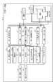
- FIG. 1 is a block diagram showing a configuration example of the electric discharge machine 1 according to the first embodiment of the present invention.
- the electric discharge machining apparatus 1 includes a material information input unit 2, a machining condition input unit 3, a storage unit 4, a comparison unit 5, a machining condition adjustment unit 6, a machining energy control unit 7, a discharge pulse detection unit 8, A discharge pulse number accumulating unit 9, a Z-axis motor control unit 10, a Z-axis motor 11, a machining power control unit 12, a machining unit 13, a machining speed calculation unit 14, a machining result storage unit 15, and an update.
- a section 16 and a jump operation control section 17 are provided.
- the machining unit 13 has an electrode 131 used in electric discharge machining and a workpiece 132 to be subjected to electric discharge machining.
- the material information input unit 2 receives input of information on the material of the electrode 131 and information on the material of the workpiece 132 from the user.
- the material information input unit 2 causes the storage unit 4 to store the received information on the material of the electrode 131 and the information on the material of the workpiece 132.
- the material of the electrode 131 may be referred to as an electrode material
- the material of the workpiece 132 may be referred to as a workpiece material.
- the machining condition input unit 3 receives an input of machining conditions for electric discharge machining from a user.
- the processing condition input unit 3 causes the storage unit 4 to store the received processing conditions. Further, the processing condition input unit 3 outputs the received processing condition to the processing energy control unit 7 and the jump operation control unit 17.
- the machining conditions of the electric discharge machining include a machining voltage which is a voltage applied during machining, a machining current which is a current flowing during machining, an application time for applying the machining voltage, a non-application time for which no machining voltage is applied, and a Jump conditions indicating operating conditions are included.
- the jump operation is a reciprocating operation of the electrode 131 performed to promote discharge of the processing waste.
- the storage unit 4 stores the material information on the electrode material and the workpiece material input to the material information input unit 2 and the machining conditions of the electric discharge machining input to the machining condition input unit 3. Further, the storage unit 4 stores an appropriate value of the number of discharge pulses per unit time during the electric discharge machining.
- An appropriate value of the number of discharge pulses per unit time is the number of discharge pulses generated per unit time at which efficient discharge machining can be realized under a combination of discharge information execution conditions such as material information or machining conditions.
- As the appropriate value of the number of discharge pulses per unit time for each combination of the execution conditions a value obtained by verification of an experiment or the like by an electric discharge machining apparatus maker is registered in the storage unit 4 in advance.
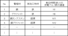
- FIG. 2 shows a combination of the electrode material information, which is information on the electrode material, and the work material information, which is information on the work material, stored in the storage unit 4 of the electric discharge machine 1 according to the first embodiment.
- FIG. 4 is a diagram showing an appropriate value of the number of discharge pulses per unit time determined from the above.
- the storage unit 4 stores appropriate values corresponding to combinations of electrode material information and workpiece material information.
- the storage unit 4 stores N1 as an appropriate value of the number of discharge pulses per unit time.
- the appropriate value of the number of discharge pulses per unit time shown in FIG. 2 is an initial value, and may be updated by a process during the electric discharge machining of the electric discharge machine 1 described later.
- the electric discharge machine 1 updates an appropriate value of the number of electric discharge pulses per unit time so that machining efficiency is maximized during machining.
- an appropriate value of the number of discharge pulses per unit time may be simply referred to as an appropriate value.
- the comparing unit 5 compares the appropriate value stored in the storage unit 4 with the integrated value of the discharge pulses per unit time calculated by the discharge pulse number integrating unit 9.
- the integrated value of the number of discharge pulses per unit time may be simply referred to as an integrated value.
- the machining condition adjusting unit 6 adjusts machining conditions related to control of machining energy during electric discharge machining based on the comparison result of the comparison unit 5.
- Processing conditions related to control of processing energy include a voltage, a current, and a voltage application time during processing.
- the processing condition adjusting unit 6 adjusts the processing conditions by setting magnifications for processing conditions such as voltage, current, and voltage application time based on the comparison result.
- the jump operation control unit 17 controls the jump operation of the electrode 131 based on the jump condition included in the processing condition input in the processing condition input unit 3.
- the processing energy control unit 7 changes the processing condition based on the processing condition input in the processing condition input unit 3 and the magnification with respect to the processing condition set in the processing condition adjustment unit 6, and changes the processing condition between the electrode 131 and the workpiece 132.
- the machining energy supplied by the machining power supply control unit 12 is controlled. That is, the processing energy control unit 7 controls the processing energy based on the content adjusted by the processing condition adjustment unit 6.
- the discharge pulse detector 8 detects a discharge pulse generated between the electrode 131 and the workpiece 132 in the machining unit 13 during the electric discharge machining.
- the discharge pulse number accumulating section 9 accumulates the number of discharge pulses detected by the discharge pulse detecting section 8 and calculates an integrated value of discharge pulses per unit time.
- the Z-axis motor control unit 10 controls the operation of the Z-axis motor 11 that operates a main shaft (not shown) that holds the electrode 131.
- the Z-axis motor 11 moves a main shaft (not shown) holding the electrode 131 in the Z-axis direction, that is, in the up-down direction, under the control of the Z-axis motor control unit 10.
- the machining power supply controller 12 supplies machining energy between the electrode 131 and the workpiece 132 based on the machining conditions of the electric discharge machining changed by the machining energy controller 7.
- the machining conditions for electric discharge machining include machining voltage, machining current, application time, non-application time, and the like.
- the machining unit 13 uses the electrode 131 to perform electrical discharge machining on a workpiece 132 which is installed in a machining tank (not shown) so as to face the electrode 131.
- the machining speed calculation unit 14 calculates the machining speed of the electric discharge machining in the machining unit 13.
- the processing result storage unit 15 stores the integrated value calculated by the discharge pulse number integrating unit 9 and the processing speed calculated by the processing speed calculation unit 14.
- the processing result storage unit 15 stores at least the current, that is, the latest integrated value and the processing speed, and the previous integrated value and the processing speed.
- the updating unit 16 updates the appropriate value stored in the storage unit 4 based on the integrated value and the processing speed stored in the processing result storage unit 15 in order to maximize the processing efficiency.
- an X-axis motor and a Y-axis motor for moving the workpiece 132 in a horizontal direction, that is, a two-dimensional direction
- an X-axis motor control unit for controlling the operation of the X-axis motor
- a Y-axis motor A description of a Y-axis motor control unit that controls the operation of the motor is omitted.
- control of the electric discharge machine 1 for keeping the number of discharge pulses generated during electric discharge machining at an appropriate value will be described.
- the electric discharge machining apparatus 1 when the integrated value of the discharge pulse is smaller than the appropriate value, the electric discharge machining apparatus 1 is expected to be less likely to generate a discharge pulse due to an excessively low concentration of machining chips. Therefore, the processing energy is controlled so that the concentration of the processing waste is increased.
- the electric discharge machining apparatus 1 when the integrated value of the discharge pulse is larger than an appropriate value, the electric discharge machining apparatus 1 is expected to abnormally generate the discharge pulse due to the excessively high concentration of the machining dust.
- FIG. 3 is a flowchart illustrating a method of controlling machining energy for keeping the number of discharge pulses generated during electric discharge machining at an appropriate value in the electric discharge machine 1 according to the first embodiment.
- the material information input unit 2 receives input of electrode material information and workpiece material information from a user (Step S1).
- the material information input unit 2 causes the storage unit 4 to store the input electrode material information and workpiece material information.
- the machining condition input unit 3 receives an input of machining conditions for electric discharge machining based on specifications required for the workpiece 132 from the user (step S2).
- the processing condition input unit 3 causes the storage unit 4 to store the input processing conditions. Further, the processing condition input unit 3 outputs the input processing conditions to the processing energy control unit 7 and the jump operation control unit 17.
- the machining power control unit 12 controls the electric discharge machining of the electrode 131 on the workpiece 132 according to the machining conditions output from the machining energy control unit 7. Further, the processing energy control unit 7 changes the processing conditions according to the magnification set by the processing condition adjustment unit 6 and controls the processing energy supplied from the processing power supply control unit 12.
- the processing unit 13 starts processing the workpiece 132 under the control of the processing power supply control unit 12 and the processing energy control unit 7 (step S3). At this time, the processing power supply control unit 12 sets a processing end flag MFLG indicating whether or not processing is being performed on the comparison unit 5.
- the discharge pulse detector 8 detects a discharge pulse generated between the electrode 131 and the workpiece 132 immediately after the start of machining.
- the discharge pulse number accumulating section 9 accumulates the number of discharge pulses detected by the discharge pulse detecting section 8, and calculates an integrated value of discharge pulses per unit time (step S4).
- the term “per unit time” refers to, for example, a period in which the electrode 131 is lowered after the electrode is lowered until the electrode is pulled up, that is, a period in which processing is performed between the jump operation and the next jump operation. Medium 100 ms, but not limited to.
- the discharge pulse number accumulating section 9 causes the accumulated value to be stored in the machining result storage section 15.
- the machining speed calculation unit 14 determines the position of the electrode 131 in the machining direction when a discharge pulse is first generated after the start of machining and, for example, the position in the machining direction 1 second after the first discharge pulse is generated after the start of machining. From the difference between the electrode 131 and the deepest machining position, the amount of advance in the machining direction per second, that is, the machining speed of electric discharge machining in the machining section 13 is calculated (step S5).
- the amount of advance in the machining direction is the distance over which the machining surface generated on the workpiece by electric discharge machining moves in the machining direction.
- the processing speed calculation unit 14 stores the calculated processing speed in the processing result storage unit 15. Note that the above one second is an example, and the present invention is not limited to this.
- the updating unit 16 stores the latest processing speed stored in the processing result storage unit 15, that is, the processing speed at the time of processing before the current jump operation, and the processing performed at the time of processing before the previous jump operation stored in the processing result storage unit 15. The speed is compared (step S6). When the processing speed at the time of processing before the current jump operation is higher than the processing speed at the time of processing before the previous jump operation (Step S6: Yes), the updating unit 16 stores the data in the storage unit 4 in order to maximize the processing efficiency. The stored appropriate value is updated with the latest value stored in the processing result storage unit 15, that is, the integrated value at the time of processing before the current jump operation (step S7).
- the storage unit 4 updates the stored appropriate value of the number of discharge pulses with the input integrated value and stores the updated value.
- the update unit 16 omits the process of step S7 when the processing speed at the time of processing before the current jump operation is equal to or lower than the processing speed at the time of processing before the previous jump operation (step S6: No).
- the processing speed at the time of processing before the current jump operation may be simply referred to as the current processing speed
- the processing speed at the time of processing before the previous jump operation may be simply referred to as the previous processing speed.
- the comparing unit 5 determines whether or not the integrated value read from the discharge pulse number integrating unit 9 is equal to the appropriate value read from the storage unit 4 (Step S11). Specifically, the comparison unit 5 calculates the ratio of the integrated value to the appropriate value by using equation (1). When the calculated ratio includes a decimal, the comparing unit 5 rounds, rounds down, or rounds up to an integer value.
- the comparing unit 5 determines that the integrated value is equivalent to an appropriate value (step S11: Yes), and integrates the current machining state.
- the value is assigned to level 5 indicating that the value is equivalent to the appropriate value (step S12).
- the current processing state level is an index indicating the degree of the ratio of the integrated value to the appropriate value, and will be described later in detail. Since the current machining state is at level 5, the comparison unit 5 instructs the machining condition adjustment unit 6 to maintain the current machining condition (step S13).
- the electric discharge machine 1 returns to the process of step S4 and performs the above-described process.
- the comparing unit 5 determines that the integrated value is not equal to the appropriate value (Step S11: No), and proceeds to the processing of Step S14. .
- the comparing unit 5 determines that the integrated value is larger than the appropriate value (Step S14: Yes) and integrates the current machining state with the appropriate value. Based on the ratio of the values, it is assigned to one of levels 6 to 10 (step S15). Since the current processing state is one of levels 6 to 10, the comparing unit 5 instructs the processing condition adjusting unit 6 to change the processing conditions so that the processing energy is reduced according to the processing described later. (Step S16). The electric discharge machine 1 returns to the process of step S4 and performs the above-described process.
- the comparing unit 5 determines that the integrated value is smaller than the appropriate value (step S14: No), and integrates the current machining state with the appropriate value. Based on the ratio of the values, the values are assigned to one of levels 0 to 4 (step S17). Since the current processing state is any one of levels 0 to 4, the comparing unit 5 instructs the processing condition adjusting unit 6 to change the processing conditions so that the processing energy is increased in accordance with the processing described later. (Step S18). The electric discharge machine 1 returns to the process of step S4 and performs the above-described process.
- the electric discharge machine 1 repeatedly performs the processes from step S4 to step S18 for each jump operation until the electric discharge machining is completed.
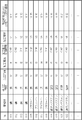
- FIG. 4 is a diagram illustrating a relationship between the current machining state level based on the ratio of the integrated value to the appropriate value and the magnification for the machining condition at each level in the electric discharge machine 1 according to the first embodiment.
- processing conditions related to control of processing energy include voltage, current, voltage application time, and the like.
- FIG. 4 when the integrated value of the discharge pulse is smaller than an appropriate value, that is, in the levels 0 to 4, it is expected that the discharge pulse is hardly generated due to the excessively low concentration of the machining waste.
- the magnification for each processing condition is set so as to increase the processing energy and increase the concentration of processing chips. Further, in FIG.
- the magnification for each processing condition is set so that the processing energy is reduced and the concentration of the processing chips is reduced.
- the magnification set for each level a value obtained in advance by verification of an experiment or the like by an electric discharge machining apparatus maker is registered. For example, when the electrode material is copper and the workpiece material is iron, the appropriate value of the number of discharge pulses per unit time is N1 from the relationship shown in FIG. Assuming that the integrated value is Nx, the comparing unit 5 calculates the ratio of the integrated value to the appropriate value by Expression (2).
- the comparison unit 5 assigns the current machining state to one of the levels 0 to 10 according to the content of FIG. 4 according to the ratio calculated using the equation (2). For example, when the ratio of the integrated value to the appropriate value is 70 [%], the comparing unit 5 assigns the current machining state to level 2.
- the processing condition adjustment unit 6 sets the magnification for the processing condition related to the control of the processing energy based on the level of the current processing state allocated by the comparison unit 5 according to the contents of FIG. For example, when the current processing state is level 2, the processing condition adjusting unit 6 changes the voltage value set in the processing condition to 1.2 times according to the contents of FIG. 4 and is set in the processing condition.
- the processing voltage application time is changed to 1.2 times, and the magnification is set so that the current value set under the processing conditions is changed to 1.8 times. Accordingly, the processing condition adjustment unit 6 provides the processing energy control unit 7 with the processing voltage V1, the processing voltage application time T1, and the processing current, which are processing conditions related to the control of the processing energy, in the next processing. I1 is changed as in the following equations (3) to (5).
- the processing condition adjustment unit 6 determines the magnification for adjusting the processing condition related to the control of the processing energy based on the ratio of the integrated value to the appropriate value.
- how to divide the ratio of the integrated value to the appropriate value and the magnification for each processing condition are merely examples, and are not limited thereto.
- the processing condition adjustment unit 6 may perform adjustment using at least one of the processing voltage V1, the voltage application time T1, and the magnification for the current value I1. For example, when the current processing state in which the integrated value is smaller than the appropriate value is level 0 to level 4, the processing condition adjusting unit 6 increases the processing voltage in the next processing with respect to the current processing and increases the voltage application time.
- the processing conditions are adjusted by setting the magnification so as to execute at least one of the following.
- the processing condition adjusting unit 6 reduces the processing voltage in the next processing with respect to the current processing and shortens the voltage application time.
- the processing conditions are adjusted by setting the magnification so as to execute at least one of the following operations.
- the processing condition adjustment unit 6 maintains the setting of the magnification for the current processing energy condition in the next processing.
- the information shown in FIG. 4 may be held by both the comparing unit 5 and the processing condition adjusting unit 6, or the processing condition adjusting unit 6 may hold the information shown in FIG. 4, and the comparing unit 5 may store the information shown in FIG. Of these, only the level and the ratio of the integrated value to the appropriate value may be held.
- the material information input unit 2 and the machining condition input unit 3 are a keyboard, a mouse, and the like used in a computer.
- the storage unit 4 and the processing result storage unit 15 are memories.
- Comparison unit 5, machining condition adjustment unit 6, machining energy control unit 7, discharge pulse detection unit 8, discharge pulse number accumulation unit 9, Z-axis motor control unit 10, machining power supply control unit 12, machining speed calculation unit 14, update unit 16 and the jump operation control unit 17 are realized by a processing circuit.
- the processing circuit may be a processor and a memory that execute a program stored in the memory, or may be dedicated hardware.
- FIG. 5 is a diagram illustrating an example of a case where the processing circuit included in the electric discharge machine 1 according to the first embodiment is configured by a processor and a memory.
- the processing circuit includes the processor 91 and the memory 92
- each function of the processing circuit of the electric discharge machine 1 is realized by software, firmware, or a combination of software and firmware.
- Software or firmware is described as a program and stored in the memory 92.
- each function is realized by the processor 91 reading and executing a program stored in the memory 92. That is, the processing circuit includes a memory 92 for storing a program that results in processing of each component of the electric discharge machine 1.
- these programs cause a computer to execute the procedure and method of each component of the electric discharge machine 1.
- the processor 91 may be a CPU (Central Processing Unit), a processing device, an arithmetic device, a microprocessor, a microcomputer, a DSP (Digital Signal Processor), or the like.
- the memory 92 includes, for example, non-volatile or volatile memory such as RAM (Random Access Memory), ROM (Read Only Memory), flash memory, EPROM (Erasable Programmable ROM), and EEPROM (registered trademark) (Electrically EPROM).
- RAM Random Access Memory
- ROM Read Only Memory
- flash memory EPROM (Erasable Programmable ROM), and EEPROM (registered trademark) (Electrically EPROM).
- Semiconductor memory a magnetic disk, a flexible disk, an optical disk, a compact disk, a mini disk, a DVD (Digital Versatile Disc), and the like.
- the processing circuit When the processing circuit is configured by dedicated hardware, the processing circuit includes, for example, a single circuit, a composite circuit, a programmed processor, a parallel programmed processor, an ASIC (Application Specific Integrated Circuit), and an FPGA (Field Programmable Gate). Array) or a combination of these.
- Each function of each component of the electric discharge machine 1 may be realized by a processing circuit for each function, or each function may be realized by a processing circuit collectively.
- a part may be realized by dedicated hardware, and a part may be realized by software or firmware.
- the processing circuit can realize the above-described functions by dedicated hardware, software, firmware, or a combination thereof.
- the electric discharge machining apparatus 1 calculates the integrated value of the discharge pulse per unit time during machining, and is determined from the combination of the electrode material information and the workpiece material information. A suitable value of the number of discharge pulses is compared with the integrated value, and the machining energy is controlled based on the comparison result.
- the electric discharge machine 1 sets a magnification for the machining condition related to the control of the machining energy, and adjusts the machining condition.
- the electric discharge machining apparatus 1 can keep the number of electric discharge pulses per unit time during machining at an appropriate value, thereby enabling efficient and stable electric discharge machining.
- the electric discharge machining apparatus 1 does not need to store machining conditions set at the time of the previous machining, so that efficient and stable electric discharge machining can be realized with simple control.
- the electric discharge machining device 1 may store the first calculated value obtained by performing the specified arithmetic processing on the appropriate value in the storage unit 4 instead of the appropriate value.
- the discharge pulse number accumulating unit 9 performs the above-described prescribed arithmetic processing on the integrated value to calculate a second calculated value.
- the electric discharge machine 1 performs a process of comparing the first calculated value based on the appropriate value and the second calculated value based on the integrated value, instead of the process of comparing the appropriate value with the integrated value.
- the electric discharge machine 1 updates the first calculated value with the second calculated value.
- the specified arithmetic processing is, for example, adding, subtracting, multiplying, or dividing a certain coefficient to an appropriate value or an integrated value, but is not limited thereto.
- Embodiment 2 the electric discharge machine 1 stores an appropriate value determined from a combination of the electrode material information and the workpiece material information, and appropriately updates the appropriate value in order to maximize machining efficiency.
- the appropriate value is affected by the processing area, processing conditions, and the like, in addition to the combination of the electrode material information and the workpiece material information.
- the processing area is the area of the processing surface where the workpiece and the electrode face each other.
- the electric discharge machining apparatus stores appropriate values determined from the combination of the electrode material information and the workpiece material information, the machining area, and the machining conditions, and appropriately optimizes the machining efficiency. Update the value. Parts different from the first embodiment will be described.
- FIG. 6 is a block diagram illustrating a configuration example of the electric discharge machining apparatus 1a according to the second embodiment.
- the electric discharge machining apparatus 1a is different from the electric discharge machining apparatus 1 of the first embodiment shown in FIG. 1 in that the storage unit 4, the machining result storage unit 15, and the update unit 16 are replaced by a storage unit 4a, a machining result storage unit 15a, The processing unit is replaced with an updating unit 16a, and a processing area calculation unit 18 is further added.
- the machining area calculator 18 calculates the machining area of the electric discharge machining for the workpiece 132. A specific calculation method in the processing area calculation unit 18 will be described later.
- the storage unit 4a stores the electrode material information and the workpiece material information input to the material information input unit 2, and the machining conditions of the electric discharge machining input to the machining condition input unit 3. Further, the storage unit 4a stores an appropriate value of the number of discharge pulses per unit time determined from a combination of the electrode material information, the workpiece material information, the processing area, and the processing conditions.
- FIG. 7 shows a discharge per unit time determined by a combination of the electrode material information, the workpiece material information, the processing area, and the processing conditions stored in the storage unit 4a of the electric discharge machining apparatus 1a according to the second embodiment. It is a figure showing the suitable value of the number of pulses.
- the storage unit 4a stores appropriate values corresponding to combinations of electrode material information, workpiece material information, processing area, and processing conditions.
- the appropriate value a value obtained in advance by verification of an experiment or the like by an EDM manufacturer is registered in the storage unit 4a.
- the storage unit 4a stores the number of discharge pulses per unit time when the processing area S1, the processing current I1, the processing voltage application time ON1, and the processing voltage V1.
- N111 is stored as an appropriate value.
- the processing conditions include the non-application time during which no processing voltage is applied, in addition to the processing current, the processing voltage application time, and the processing voltage, as described above. Good.
- the electric discharge machining apparatus 1a updates an appropriate value of the number of electric discharge pulses per unit time so that machining efficiency is maximized during machining.
- the machining result storage unit 15a stores the integrated value calculated by the discharge pulse number integrating unit 9, the machining speed calculated by the machining speed calculation unit 14, and the machining area calculated by the machining area calculation unit 18.
- the processing result storage unit 15a stores at least the current, that is, the latest integrated value, the processing speed, and the processing area, and the previous integrated value, the processing speed, and the processing area.
- the updating unit 16a updates the appropriate value stored in the storage unit 4a based on the integrated value, the processing speed, and the processing area stored in the processing result storage unit 15a in order to maximize the processing efficiency.
- FIG. 8 is a flowchart showing a method of controlling machining energy for maintaining the number of discharge pulses generated during electric discharge machining at an appropriate value in the electric discharge machine 1a according to the second embodiment.
- the processing from step S1 to step S5 is the same as the processing from step S1 to step S5 in the flowchart of the first embodiment shown in FIG.
- the machining area calculation unit 18 calculates the machining area using Expression (6) (Step S21).
- ⁇ Machining area (number of discharge pulses ⁇ amount of machining per discharge pulse) / amount of advance in machining direction ⁇ (6)
- the machining amount per discharge pulse indicates the volume of the workpiece removed in the machining direction by machining per discharge pulse, and includes electrode material information and workpiece material information. It is assumed that the machining voltage, machining current, and the like are determined from a combination of set execution conditions and are stored in a machining amount storage unit (not shown) in the electric discharge machine 1a.
- the processing area calculation unit 18 stores the calculated processing area in the processing result storage unit 15a.
- the update unit 16a compares the latest processing speed stored in the processing result storage unit 15a, that is, the processing speed at the time of the current processing, with the processing speed at the previous processing stored in the processing result storage unit 15a (step S6). ). When the processing speed in the current processing is higher than the processing speed in the previous processing (step S6: Yes), the update unit 16a sets the optimal value stored in the storage unit 4a to maximize the processing efficiency. The appropriate value that matches the electrode material information, the workpiece material information, the processing area, and the processing condition is updated with the latest value stored in the processing result storage unit 15a, that is, the integrated value at the time of the current processing (step S7). .
- the storage unit 4a updates and stores an appropriate value that matches the processing area and the processing condition with the input integrated value.
- the update unit 16a omits the process of step S7 when the processing speed at the time of the current processing is equal to or lower than the processing speed at the time of the previous processing (step S6: No).
- step S11 the comparison unit 5 compares the integrated value with the appropriate value that matches the electrode material information, the workpiece material information, the machining area, and the machining condition in the current electric discharge machining. I do.
- the appropriate value of the number of discharge pulses during machining varies not only by the combination of the electrode material information and the workpiece material information but also by the machining area and machining conditions. For example, the number of discharge pulses is larger when the machining area is large than when the machining area is small. Further, the number of discharge pulses increases as the machining voltage increases, and increases as the machining current increases. Therefore, as shown in FIG. 7, the appropriate value of the number of discharge pulses during machining can be further subdivided by giving, for example, machining conditions including machining voltage and information on machining area.
- the electric discharge machining apparatus 1a can accurately control the integrated value, that is, the number of electric discharge pulses during machining, by using appropriate values that are more subdivided than in the first embodiment.
- the electric discharge machining apparatus 1a when the machining area can be grasped in advance by machining such as a square shape, the user directly inputs the machining area to the electric discharge machining apparatus 1a via a machining area input unit (not shown). Is also good. This eliminates the need for the electric discharge machining apparatus 1a to estimate the machining area, and thus enables the discharge pulse number to be kept at an appropriate value immediately after machining starts. In this case, in the electric discharge machining apparatus 1a, the process of step S21 for calculating the machining area in the flowchart shown in FIG.
- the electric discharge machining apparatus 1a stores an appropriate value according to a combination of the electrode material information, the workpiece material information, the machining area, and the machining condition, and The machining energy is controlled using an appropriate value based on the machining state, that is, an appropriate value that matches the electrode material information, the workpiece material information, the machining area, and the machining condition in the current electric discharge machining.
- the electric discharge machining apparatus 1a can control the integrated value, that is, the number of electric discharge pulses during machining with high accuracy, by using appropriate values that are more subdivided than in the first embodiment.
- the configuration shown in the above embodiment is an example of the content of the present invention, and can be combined with another known technology, and the configuration of the configuration is not deviated from the gist of the present invention. Some of them can be omitted or changed.
Landscapes
- Engineering & Computer Science (AREA)
- Mechanical Engineering (AREA)
- Electrical Discharge Machining, Electrochemical Machining, And Combined Machining (AREA)
Abstract
放電加工装置(1)は、電極材情報及び被加工物材情報の入力を受け付ける材料情報入力部(2)と、放電加工の加工条件の入力を受け付ける加工条件入力部(3)と、放電加工中に発生する放電パルスを検出する放電パルス検出部(8)と、放電パルスの数を積算し、単位時間当たりの放電パルスの積算値を算出する放電パルス数積算部(9)と、加工条件に基づいて放電加工の加工エネルギーを制御する加工エネルギー制御部(7)と、電極材情報と被加工物材情報との組合せから決定される放電加工中の単位時間当たりの放電パルス数の適値が記憶されている記憶部(4)と、電極材情報及び被加工物材情報が合致する適値と積算値とを比較する比較部(5)と、適値と積算値との比較結果に基づいて加工条件を調整する加工条件調整部(6)と、を備える。
Description
本発明は、放電加工を行う放電加工装置及び加工エネルギー制御方法に関する。
形彫放電加工を行う放電加工装置は、効率的に放電加工を行うためには放電パルス数を適切に制御する必要がある。特許文献1には、放電加工装置において、放電加工を進行させるべき目標方向(以後、加工方向という)への加工に寄与しない側面方向への放電パルスの割合を算出し、この割合が一定の値を超えたとき、側面方向への放電パルスの増加により、加工方向への加工効率が低下していると判断し、加工間隙間に印加する平均電圧を下げて加工エネルギーを制御することで、側面放電の原因となっている加工屑の発生を抑えて側面放電の割合を下げ、加工方向への加工効率を向上させる技術が開示されている。
形彫放電加工を行う放電加工装置は、単位時間当たりの放電パルス数が最適な範囲、いわゆる適値から外れると加工が不安定になり、放電加工により被加工物に生じる加工面が加工方向に移動する速度である加工速度が低下し、効率的な放電加工を行うことができない。放電加工装置は、効率的に放電加工を行うためには放電パルス数を適値に保つ必要がある。
しかしながら、特許文献1に記載の放電加工装置のように、加工中の側面方向への放電パルスの割合が一定の値を超えたか否かで、加工エネルギーを制御するだけでは、放電パルス数が適値から外れているか否かを判定することができないため、加工効率化及び不安定状態の回避には不十分であった。
本発明は、上記に鑑みてなされたものであって、効率的かつ安定的な放電加工を実現できる放電加工装置を得ることを目的とする。
上述した課題を解決し、目的を達成するために、本発明の放電加工装置は、放電加工で使用される電極の材料に関する電極材情報、及び放電加工の被加工物の材料に関する被加工物材情報の入力を受け付ける材料情報入力部と、放電加工の加工条件の入力を受け付ける加工条件入力部と、放電加工中に発生する放電パルスを検出する放電パルス検出部と、放電パルスの数を積算し、単位時間当たりの放電パルスの積算値を算出する放電パルス数積算部と、を備える。また、放電加工装置は加工条件に基づいて放電加工の加工エネルギーを制御する加工エネルギー制御部と、電極材情報と被加工物材情報との組合せから決定される放電加工中の単位時間当たりの放電パルス数の適値が記憶されている記憶部と、電極材情報及び被加工物材情報が合致する適値と、積算値とを比較する比較部と、適値と積算値との比較結果に基づいて加工条件を調整する加工条件調整部と、を備えたことを特徴とする。
本発明にかかる放電加工装置は、効率的かつ安定的な放電加工を実現できるという効果を奏する。
以下に、本発明の実施の形態にかかる放電加工装置及び加工エネルギー制御方法を図面に基づいて詳細に説明する。なお、この実施の形態によりこの発明が限定されるものではない。
実施の形態1.
図1は、本発明の実施の形態1にかかる放電加工装置1の構成例を示すブロック図である。放電加工装置1は、材料情報入力部2と、加工条件入力部3と、記憶部4と、比較部5と、加工条件調整部6と、加工エネルギー制御部7と、放電パルス検出部8と、放電パルス数積算部9と、Z軸モータ制御部10と、Z軸モータ11と、加工電源制御部12と、加工部13と、加工速度算出部14と、加工実績記憶部15と、更新部16と、ジャンプ動作制御部17と、を備える。加工部13は、放電加工で使用される電極131と、放電加工の加工対象となる被加工物132と、を有する。
図1は、本発明の実施の形態1にかかる放電加工装置1の構成例を示すブロック図である。放電加工装置1は、材料情報入力部2と、加工条件入力部3と、記憶部4と、比較部5と、加工条件調整部6と、加工エネルギー制御部7と、放電パルス検出部8と、放電パルス数積算部9と、Z軸モータ制御部10と、Z軸モータ11と、加工電源制御部12と、加工部13と、加工速度算出部14と、加工実績記憶部15と、更新部16と、ジャンプ動作制御部17と、を備える。加工部13は、放電加工で使用される電極131と、放電加工の加工対象となる被加工物132と、を有する。
材料情報入力部2は、ユーザから、電極131の材料に関する情報、及び被加工物132の材料に関する情報の入力を受け付ける。材料情報入力部2は、受け付けた電極131の材料に関する情報及び被加工物132の材料に関する情報を記憶部4に記憶させる。以降の説明において、電極131の材料を電極材と称し、被加工物132の材料を被加工物材と称することがある。
加工条件入力部3は、ユーザから、放電加工の加工条件の入力を受け付ける。加工条件入力部3は、受け付けた加工条件を記憶部4に記憶させる。また、加工条件入力部3は、受け付けた加工条件を加工エネルギー制御部7及びジャンプ動作制御部17へ出力する。放電加工の加工条件には、加工時に印加する電圧である加工電圧、加工時に流す電流である加工電流、加工電圧を印加する印加時間、加工電圧を印加しない非印加時間、電極131のジャンプ動作の動作条件を示すジャンプ条件などが含まれる。ジャンプ動作とは、加工屑の排出を促すために行う電極131の往復動作である。
記憶部4は、材料情報入力部2に入力された電極材と被加工物材に関する材料情報、及び加工条件入力部3に入力された放電加工の加工条件を記憶する。また、記憶部4は、放電加工中の単位時間当たりの放電パルス数の適値を記憶している。単位時間当たりの放電パルス数の適値は、材料情報、又は加工条件といった放電加工の実施条件の組合せにおいて、効率的な放電加工を実現できる単位時間当たりに発生する放電パルスの数である。各実施条件の組合せに対する単位時間当たりの放電パルス数の適値は、事前に放電加工装置メーカによって、実験等の検証により求められた値が記憶部4に登録されている。一般的に、放電パルスの発生のし易さは、電極材と被加工物材との組合せによって異なることがある。すなわち、単位時間当たりの放電パルス数の適値は、電極材と被加工物材との組合せに影響される。図2は、実施の形態1にかかる放電加工装置1の記憶部4が記憶している、電極材に関する情報である電極材情報と被加工物材に関する情報である被加工物材情報との組合せから決められる単位時間当たりの放電パルス数の適値を示す図である。記憶部4には、電極材情報、及び被加工物材情報の組合せに応じた適値が記憶されている。記憶部4は、例えば、電極材が銅で被加工物材が鉄の場合、単位時間当たりの放電パルス数の適値としてN1を記憶している。なお、図2に示す単位時間当たりの放電パルス数の適値は、初期値であり、後述する放電加工装置1の放電加工中の処理によって更新される場合がある。放電加工装置1は、加工中において加工効率が最大になるように、単位時間当たりの放電パルス数の適値を更新する。以降の説明において、単位時間当たりの放電パルス数の適値を単に適値と称する場合がある。
比較部5は、記憶部4に記憶されている適値と、放電パルス数積算部9で算出された単位時間当たりの放電パルスの積算値とを比較する。以降の説明において、単位時間当たりの放電パルス数の積算値を単に積算値と称する場合がある。
加工条件調整部6は、比較部5の比較結果に基づいて、放電加工中の加工エネルギーの制御に関係する加工条件を調整する。加工エネルギーの制御に関係する加工条件は、加工時の電圧、電流、電圧印加時間などである。具体的には、加工条件調整部6は、電圧、電流、電圧印加時間などの加工条件に対する倍率を比較結果に基づいて設定することで、加工条件を調整する。
ジャンプ動作制御部17は、加工条件入力部3において入力された加工条件に含まれるジャンプ条件に基づいて、電極131のジャンプ動作を制御する。
加工エネルギー制御部7は、加工条件入力部3において入力された加工条件と、加工条件調整部6で設定される加工条件に対する倍率に基づいて加工条件を変更し、電極131、被加工物132間に対して加工電源制御部12が供給する加工エネルギーを制御する。すなわち、加工エネルギー制御部7は、加工条件調整部6で調整された内容で加工エネルギーを制御する。
放電パルス検出部8は、放電加工中の加工部13において、電極131と被加工物132との間で発生する放電パルスを検出する。
放電パルス数積算部9は、放電パルス検出部8において検出された放電パルスの数を積算し、単位時間当たりの放電パルスの積算値を算出する。
Z軸モータ制御部10は、電極131を保持する図示しない主軸を動作させるZ軸モータ11の動作を制御する。
Z軸モータ11は、Z軸モータ制御部10の制御に基づいて、電極131を保持する図示しない主軸をZ軸方向すなわち上下方向に移動させる。
加工電源制御部12は、加工エネルギー制御部7において変更された放電加工の加工条件に基づいて、電極131、被加工物132間に対して加工エネルギーを供給する。前述のように、放電加工の加工条件には、加工電圧、加工電流、印加時間、非印加時間などが含まれる。
加工部13は、電極131を用いて、電極131に対向して図示しない加工槽に設置される被加工物132を放電加工する。
加工速度算出部14は、加工部13における放電加工の加工速度を算出する。
加工実績記憶部15は、放電パルス数積算部9で算出された積算値、及び加工速度算出部14で算出された加工速度を記憶する。加工実績記憶部15は、少なくとも、今回すなわち最新の積算値及び加工速度と、前回の積算値及び加工速度とを記憶している。
更新部16は、加工効率を最大化させるため、加工実績記憶部15に記憶されている積算値及び加工速度に基づいて、記憶部4に記憶されている適値を更新する。
なお、図1に示す放電加工装置1では、被加工物132を水平方向すなわち2次元方向に移動させるX軸モータ及びY軸モータ、X軸モータの動作を制御するX軸モータ制御部、Y軸モータの動作を制御するY軸モータ制御部などは記載を省略している。
つづいて、放電加工装置1が、放電加工中に発生する放電パルスの数を適値に保つ制御について説明する。本実施の形態において、放電加工装置1は、放電パルスの積算値が適値より小さい場合、加工屑濃度が過小になっていることが原因で放電パルスが発生しにくくなっていると予想されるため、加工屑濃度が増えるように加工エネルギーを制御する。また、放電加工装置1は、放電パルスの積算値が適値より大きい場合、加工屑濃度が過大になっていることが原因で放電パルスが異常発生していると予想されるため、加工屑濃度が減るように加工エネルギーを制御する。放電パルス数と加工屑濃度には相関関係があることから、放電加工装置1は、加工屑濃度を適値に保つように加工エネルギーを制御することによって、放電パルス数を適値に保つことができる。図3は、実施の形態1にかかる放電加工装置1において、放電加工中に発生する放電パルスの数を適値に保つための加工エネルギーの制御方法を示すフローチャートである。
放電加工装置1において、材料情報入力部2は、ユーザから、電極材情報及び被加工物材情報の入力を受け付ける(ステップS1)。材料情報入力部2は、入力された電極材情報及び被加工物材情報を記憶部4に記憶させる。
加工条件入力部3は、ユーザから、被加工物132に要求される仕様に基づく放電加工の加工条件の入力を受け付ける(ステップS2)。加工条件入力部3は、入力された加工条件を記憶部4に記憶させる。また、加工条件入力部3は、入力された加工条件を加工エネルギー制御部7及びジャンプ動作制御部17へ出力する。
加工電源制御部12は、加工エネルギー制御部7から出力される加工条件に従って、被加工物132に対する電極131の放電加工を制御する。また、加工エネルギー制御部7は、加工条件調整部6で設定される倍率に従って加工条件を変更し、加工電源制御部12から供給される加工エネルギーを制御する。加工部13は、加工電源制御部12及び加工エネルギー制御部7の制御によって、被加工物132に対する加工を開始する(ステップS3)。このとき、加工電源制御部12は、比較部5に対して、加工中か否かを示す加工終了フラグMFLGを設定する。加工電源制御部12は、加工中は加工終了フラグMFLG=1に設定する。加工電源制御部12は、加工条件に指定される最終条件の加工が完了した際に加工終了フラグMFLG=0に設定する。
放電パルス検出部8は、加工開始直後から、電極131と被加工物132との間に発生する放電パルスを検出する。放電パルス数積算部9は、放電パルス検出部8において検出された放電パルスの数を積算し、単位時間当たりの放電パルスの積算値を算出する(ステップS4)。単位時間当たりとは、例えば、電極131が電極降下後から電極引き上げまでの電極が降下された状態の期間、すなわちジャンプ動作と次のジャンプ動作との間の加工を行っている期間であるジャンプダウン中の100ミリ秒であるが、これに限定されない。放電パルス数積算部9は、積算値を加工実績記憶部15に記憶させる。
加工速度算出部14は、加工開始後最初に放電パルスが発生した際の加工方向の電極131の位置と、例えば、加工開始後最初に放電パルスが発生してから1秒経過後の加工方向の電極131の最深加工位置との差分から1秒当たりの加工方向の進み量、すなわち加工部13での放電加工の加工速度を算出する(ステップS5)。ここで、加工方向の進み量とは放電加工により被加工物に生じる加工面が加工方向に移動する距離である。加工速度算出部14は、算出した加工速度を加工実績記憶部15に記憶させる。なお、上記の1秒は一例であり、これに限定されない。
更新部16は、加工実績記憶部15に記憶されている最新すなわち今回のジャンプ動作前の加工時の加工速度と、加工実績記憶部15に記憶されている前回のジャンプ動作前の加工時の加工速度とを比較する(ステップS6)。更新部16は、今回のジャンプ動作前の加工時の加工速度が前回のジャンプ動作前の加工時の加工速度より大きい場合(ステップS6:Yes)、加工効率を最大化させるため、記憶部4に記憶されている適値を、加工実績記憶部15に記憶されている最新すなわち今回のジャンプ動作前の加工時の積算値で更新する(ステップS7)。記憶部4は、更新部16から新しく積算値が入力された場合、記憶していた放電パルス数の適値を入力された積算値で更新し、記憶する。更新部16は、今回のジャンプ動作前の加工時の加工速度が前回のジャンプ動作前の加工時の加工速度以下の場合(ステップS6:No)、ステップS7の処理を省略する。なお、今回のジャンプ動作前の加工時の加工速度を単に今回の加工速度と称し、前回のジャンプ動作前の加工時の加工速度を単に前回の加工速度と称する場合がある。
比較部5は、記憶部4から放電加工で使用される電極材に関する電極材情報、及び被加工物材に関する被加工物材情報が合致する放電パルス数の適値を読み出す(ステップS8)。また、比較部5は、放電パルス数積算部9から算出された放電パルスの積算値を読み出す(ステップS9)。比較部5は、加工終了フラグMFLGの値を確認する(ステップS10)。比較部5は、加工終了フラグMFLG=0の場合(ステップS10:Yes)、加工が完了しているとして処理を終了する。比較部5は、加工終了フラグMFLG≠0の場合(ステップS10:No)、ステップS11の処理に進む。
比較部5は、放電パルス数積算部9から読み出した積算値が、記憶部4から読み出した適値と同等か否かを判定する(ステップS11)。具体的には、比較部5は、適値に対する積算値の割合を式(1)にて算出する。なお、比較部5は、算出された割合が小数を含む場合、四捨五入、切り捨て、または切り上げによって整数の値にする。
適値に対する積算値の割合=(積算値/適値)×100[%] …(1)
比較部5は、式(1)で算出された割合が96~105[%]の場合、積算値は適値と同等であると判定し(ステップS11:Yes)、現在の加工状態を、積算値が適値と同等であることを示すレベル5に振り分ける(ステップS12)。現在の加工状態のレベルとは、適値に対する積算値の割合の程度を表す指標であり、詳細については後述する。比較部5は、現在の加工状態がレベル5であることから、加工条件調整部6に対して、現在の加工条件を維持することを指示する(ステップS13)。放電加工装置1は、ステップS4の処理に戻って前述の処理を実施する。比較部5は、式(1)で算出された値が96~105[%]ではない場合、積算値は適値と同等ではないと判定し(ステップS11:No)、ステップS14の処理に進む。
比較部5は、式(1)で算出された割合が106[%]以上の場合、積算値は適値より大きいと判定し(ステップS14:Yes)、現在の加工状態を、適値に対する積算値の割合に基づき、レベル6~10のいずれかに振り分ける(ステップS15)。比較部5は、現在の加工状態がレベル6~10のいずれかであることから、加工条件調整部6に対して、加工条件を後述する処理に従って加工エネルギーが小さくなるように変更することを指示する(ステップS16)。放電加工装置1は、ステップS4の処理に戻って前述の処理を実施する。
比較部5は、式(1)で算出された値が95[%]以下の場合、積算値は適値より小さいと判定し(ステップS14:No)、現在の加工状態を、適値に対する積算値の割合に基づき、レベル0~4のいずれかに振り分ける(ステップS17)。比較部5は、現在の加工状態がレベル0~4のいずれかであることから、加工条件調整部6に対して、加工条件を後述する処理に従って加工エネルギーが大きくなるように変更することを指示する(ステップS18)。放電加工装置1は、ステップS4の処理に戻って前述の処理を実施する。
放電加工装置1は、ステップS4からステップS18までの処理を、ジャンプ動作毎に、放電加工を終了するまで繰り返し実施する。
現在の加工状態のレベル、及び加工条件調整部6における加工条件を調整する処理について説明する。図4は、実施の形態1にかかる放電加工装置1において、適値に対する積算値の割合に基づく現在の加工状態のレベルと、各レベルにおける加工条件に対する倍率との関係を示す図である。前述のように、加工エネルギーの制御に関係する加工条件は、電圧、電流、電圧印加時間などである。図4において、放電パルスの積算値が適値より小さい場合、すなわちレベル0~4では、加工屑濃度が過小になっていることが原因で放電パルスが発生しにくくなっていると予想されるので、加工エネルギーを大きくして加工屑濃度が増えるように各加工条件に対する倍率が設定されている。また、図4において、放電パルスの積算値が適値より大きい場合、すなわちレベル6~10では、加工屑濃度が過大になっていることが原因で放電パルスが異常発生していると予想されるので、加工エネルギーを小さくして加工屑濃度が減るように各加工条件に対する倍率が設定されている。各レベル毎に設定されている倍率は、事前に放電加工装置メーカによって、実験等の検証により求められた値が登録されている。例えば、電極材が銅で被加工物材が鉄の場合、図2に示す関係から単位時間当たりの放電パルス数の適値はN1である。比較部5は、積算値をNxとすると、式(2)によって適値に対する積算値の割合を算出する。
適値に対する積算値の割合=(Nx/N1)×100[%] …(2)
比較部5は、式(2)を用いて算出した割合に応じて、図4の内容に従って現在の加工状態をレベル0~10のいずれかに振り分ける。比較部5は、例えば、適値に対する積算値の割合が70[%]である場合、現在の加工状態をレベル2に振り分ける。加工条件調整部6は、比較部5によって振り分けられた現在の加工状態のレベルに基づいて、加工エネルギーの制御に関係する加工条件に対する倍率を、図4の内容に従って設定する。加工条件調整部6は、例えば、現在の加工状態がレベル2の場合、図4の内容に従って、加工条件で設定されている電圧値を1.2倍に変更し、加工条件で設定されている加工電圧印加時間を1.2倍に変更し、加工条件で設定されている電流値を1.8倍に変更するように倍率を設定する。これにより、加工条件調整部6は、次の加工のとき、加工エネルギー制御部7に対して、加工エネルギーの制御に関係する加工条件である、加工電圧V1、加工電圧印加時間T1、及び加工電流I1を次の式(3)~式(5)のように変更させる。
次の加工時の加工電圧=V1×1.2 …(3)
次の加工時の加工電圧印加時間=T1×1.2 …(4)
次の加工時の加工電流=I1×1.8 …(5)
次の加工時の加工電圧印加時間=T1×1.2 …(4)
次の加工時の加工電流=I1×1.8 …(5)
このように、加工条件調整部6は、適値に対する積算値の割合に基づいて、加工エネルギーの制御に関係する加工条件を調整する倍率を決定する。なお、図4において、適値に対する積算値の割合の区切り方、及び各加工条件に対する倍率は一例であり、これに限定されない。また、加工条件調整部6は、加工電圧V1、電圧印加時間T1、電流値I1に対する倍率のうち、少なくとも1つを用いて調整するようにしてもよい。例えば、加工条件調整部6は、積算値が適値より小さい現在の加工状態がレベル0~4の場合、今回の加工に対して次回の加工において、加工電圧を大きくする、電圧印加時間を長くする、加工電流を大きくする、のうち少なくとも1つを実行するように倍率を設定して加工条件を調整する。また、加工条件調整部6は、積算値が適値より大きい現在の加工状態がレベル6~10の場合、今回の加工に対して次回の加工において、加工電圧を小さくする、電圧印加時間を短くする、加工電流を小さくする、のうち少なくとも1つを実行するように倍率を設定して加工条件を調整する。なお、加工条件調整部6は、積算値が適値と同等の現在の加工状態がレベル5の場合、次回の加工において今回の加工エネルギー条件に対する倍率の設定を維持する。図4に示す情報については比較部5及び加工条件調整部6がともに保持していてもよいし、加工条件調整部6が図4に示す情報を保持し、比較部5が図4に示す情報のうちレベル及び適値に対する積算値の割合の部分のみを保持していてもよい。
つづいて、放電加工装置1のハードウェア構成について説明する。放電加工装置1において、材料情報入力部2及び加工条件入力部3は、コンピュータで使用されるキーボード、マウスなどである。記憶部4及び加工実績記憶部15はメモリである。比較部5、加工条件調整部6、加工エネルギー制御部7、放電パルス検出部8、放電パルス数積算部9、Z軸モータ制御部10、加工電源制御部12、加工速度算出部14、更新部16、およびジャンプ動作制御部17は処理回路により実現される。処理回路は、メモリに格納されるプログラムを実行するプロセッサ及びメモリであってもよいし、専用のハードウェアであってもよい。
図5は、実施の形態1にかかる放電加工装置1が備える処理回路をプロセッサ及びメモリで構成する場合の例を示す図である。処理回路がプロセッサ91及びメモリ92で構成される場合、放電加工装置1の処理回路の各機能は、ソフトウェア、ファームウェア、またはソフトウェアとファームウェアとの組合せにより実現される。ソフトウェアまたはファームウェアはプログラムとして記述され、メモリ92に格納される。処理回路では、メモリ92に記憶されたプログラムをプロセッサ91が読み出して実行することにより、各機能を実現する。すなわち、処理回路は、放電加工装置1の各構成要素の処理が結果的に実行されることになるプログラムを格納するためのメモリ92を備える。また、これらのプログラムは、放電加工装置1の各構成要素の手順及び方法をコンピュータに実行させるものであるともいえる。
ここで、プロセッサ91は、CPU(Central Processing Unit)、処理装置、演算装置、マイクロプロセッサ、マイクロコンピュータ、またはDSP(Digital Signal Processor)などであってもよい。また、メモリ92には、例えば、RAM(Random Access Memory)、ROM(Read Only Memory)、フラッシュメモリ、EPROM(Erasable Programmable ROM)、EEPROM(登録商標)(Electrically EPROM)などの、不揮発性または揮発性の半導体メモリ、磁気ディスク、フレキシブルディスク、光ディスク、コンパクトディスク、ミニディスク、またはDVD(Digital Versatile Disc)などが該当する。
処理回路が専用のハードウェアで構成される場合、処理回路は、例えば、単一回路、複合回路、プログラム化したプロセッサ、並列プログラム化したプロセッサ、ASIC(Application Specific Integrated Circuit)、FPGA(Field Programmable Gate Array)、またはこれらを組合せたものが該当する。放電加工装置1の各構成要素の各機能を機能別に処理回路で実現してもよいし、各機能をまとめて処理回路で実現してもよい。
なお、放電加工装置1の各構成要素の各機能について、一部を専用のハードウェアで実現し、一部をソフトウェアまたはファームウェアで実現するようにしてもよい。このように、処理回路は、専用のハードウェア、ソフトウェア、ファームウェア、またはこれらの組合せによって、上述の各機能を実現することができる。
以上説明したように、本実施の形態によれば、放電加工装置1は、加工中の単位時間当たりの放電パルスの積算値を算出し、電極材情報及び被加工物材情報の組合せから決定される放電パルス数の適値と積算値とを比較し、比較結果に基づいて加工エネルギーを制御する。放電加工装置1は、加工エネルギーの変更が必要な場合、加工エネルギーの制御に関係する加工条件に対する倍率を設定して、加工条件を調整する。これにより、放電加工装置1は、加工中の単位時間当たりの放電パルス数を適値に保つことができ、効率的かつ安定的な放電加工が可能となる。また、放電加工装置1は、前回の加工時に設定されていた加工条件を記憶しておく必要がないため、簡易な制御で効率的かつ安定的な放電加工を実現できる。
なお、放電加工装置1は、適値に替えて、適値に対して規定された演算処理を行って得られた第1の算出値を記憶部4に記憶しておくことも可能である。この場合、放電加工装置1では、放電パルス数積算部9が、積算値に対して前述の規定された演算処理を行って第2の算出値を算出する。放電加工装置1は、適値と積算値とを比較する処理に替えて、適値に基づく第1の算出値と積算値に基づく第2の算出値とを比較する処理を行う。放電加工装置1は、加工速度に基づいて記憶部4に記憶されている第1の算出値を更新する場合、第2の算出値で更新する。規定された演算処理は、例えば、適値または積算値に対してある係数を加算、減算、乗算、または除算することであるが、これらに限定されない。
実施の形態2.
実施の形態1では、放電加工装置1は、電極材情報と被加工物材情報との組合せから決定される適値を記憶し、加工効率を最大化させるため、適宜適値を更新していた。しかしながら、適値は、電極材情報と被加工物材情報との組合せの他、加工面積、加工条件などにも影響される。加工面積とは、被加工物と電極が対向している加工面の面積である。実施の形態2では、放電加工装置は、電極材情報と被加工物材情報との組合せ、加工面積、及び加工条件から決定される適値を記憶し、加工効率を最大化させるため、適宜適値を更新する。実施の形態1と異なる部分について説明する。
実施の形態1では、放電加工装置1は、電極材情報と被加工物材情報との組合せから決定される適値を記憶し、加工効率を最大化させるため、適宜適値を更新していた。しかしながら、適値は、電極材情報と被加工物材情報との組合せの他、加工面積、加工条件などにも影響される。加工面積とは、被加工物と電極が対向している加工面の面積である。実施の形態2では、放電加工装置は、電極材情報と被加工物材情報との組合せ、加工面積、及び加工条件から決定される適値を記憶し、加工効率を最大化させるため、適宜適値を更新する。実施の形態1と異なる部分について説明する。
図6は、実施の形態2にかかる放電加工装置1aの構成例を示すブロック図である。放電加工装置1aは、図1に示す実施の形態1の放電加工装置1に対して、記憶部4、加工実績記憶部15、及び更新部16を、記憶部4a、加工実績記憶部15a、及び更新部16aに置き換え、さらに、加工面積算出部18を追加したものである。
加工面積算出部18は、被加工物132に対する放電加工の加工面積を算出する。加工面積算出部18における具体的な算出方法については後述する。
記憶部4aは、材料情報入力部2に入力された電極材情報と被加工物材情報、及び加工条件入力部3に入力された放電加工の加工条件を記憶する。また、記憶部4aは、電極材情報、被加工物材情報、加工面積、及び加工条件の組合せから決定される単位時間当たりの放電パルス数の適値を記憶している。図7は、実施の形態2にかかる放電加工装置1aの記憶部4aが記憶している、電極材情報、被加工物材情報、加工面積、及び加工条件の組合せから決められる単位時間当たりの放電パルス数の適値を示す図である。記憶部4aには、電極材情報、被加工物材情報、加工面積、及び加工条件の組合せに応じた適値が記憶されている。適値は、事前に放電加工装置メーカによって、実験等の検証により求められた値が記憶部4aに登録されている。記憶部4aは、例えば、電極材が銅、被加工物材が鉄の場合、加工面積S1、加工電流I1、加工電圧印加時間ON1、及び加工電圧V1の場合、単位時間当たりの放電パルス数の適値としてN111を記憶している。加工条件には、前述のように、加工電流、加工電圧印加時間、加工電圧の他に、加工電圧を印加しない非印加時間も含まれるため、図7に非印加時間の項目を追加してもよい。なお、図7に示す単位時間当たりの放電パルス数の適値は、初期値であり、後述する放電加工装置1aの放電加工中の処理によって更新される場合がある。放電加工装置1aは、加工中において加工効率が最大になるように、単位時間当たりの放電パルス数の適値を更新する。
加工実績記憶部15aは、放電パルス数積算部9で算出された積算値、加工速度算出部14で算出された加工速度、及び加工面積算出部18で算出された加工面積を記憶する。加工実績記憶部15aは、少なくとも、今回すなわち最新の積算値、加工速度、及び加工面積と、前回の積算値、加工速度、及び加工面積とを記憶している。
更新部16aは、加工効率を最大化させるため、加工実績記憶部15aに記憶されている積算値、加工速度、及び加工面積に基づいて、記憶部4aに記憶されている適値を更新する。
つづいて、放電加工装置1aが、放電加工中に発生する放電パルスの数を適値に保つ制御について説明する。図8は、実施の形態2にかかる放電加工装置1aにおいて、放電加工中に発生する放電パルスの数を適値に保つための加工エネルギーの制御方法を示すフローチャートである。図8に示すフローチャートにおいてステップS1からステップS5までの処理は、図3に示す実施の形態1のフローチャートのステップS1からステップS5までの処理と同様である。
放電加工装置1aにおいて、加工面積算出部18は、式(6)を用いて加工面積を算出する(ステップS21)。
加工面積=(放電パルス数×放電パルス1発あたりの加工量)/加工方向の進み量 …(6)
式(6)において、放電パルス1発あたりの加工量は、放電パルス1発あたりの加工で加工方向に除去される被加工物の体積量を示しており、電極材情報、被加工物材情報、加工電圧、加工電流等が設定されている実施条件の組合せから決定され、放電加工装置1aにおいて、図示しない加工量記憶部に記憶されているものとする。加工面積算出部18は、算出した加工面積を加工実績記憶部15aに記憶させる。
更新部16aは、加工実績記憶部15aに記憶されている最新すなわち今回の加工時の加工速度と、加工実績記憶部15aに記憶されている前回の加工時の加工速度とを比較する(ステップS6)。更新部16aは、今回の加工時の加工速度が前回の加工時の加工速度より大きい場合(ステップS6:Yes)、加工効率を最大化させるため、記憶部4aに記憶されている適値のうち、電極材情報、被加工物材情報、加工面積、及び加工条件が合致する適値を、加工実績記憶部15aに記憶されている最新すなわち今回の加工時の積算値で更新する(ステップS7)。記憶部4aは、更新部16aから新しく加工面積、加工条件、及び積算値が入力された場合、加工面積及び加工条件が合致する適値を入力された積算値で更新し、記憶する。更新部16aは、今回の加工時の加工速度が前回の加工時の加工速度以下の場合(ステップS6:No)、ステップS7の処理を省略する。
図8に示すフローチャートにおいて以降のステップS8からステップS18までの処理は、図3に示す実施の形態1のフローチャートのステップS8からステップS18までの処理と同様である。実施の形態2において、比較部5は、ステップS11の処理では、現在の放電加工において電極材情報、被加工物材情報、加工面積、及び加工条件が合致する適値と、積算値とを比較する。
加工中の放電パルス数の適値は、電極材情報及び被加工物材情報の組合せだけでなく、加工面積、加工条件などによって少なからず変動する。例えば、放電パルス数は、加工面積が大きい場合の方が、加工面積が小さい場合よりも多くなる。また、放電パルス数は、加工電圧が大きい程多くなり、加工電流が大きい程多くなる。従って、加工中の放電パルス数の適値は、図7に示すように、例えば、加工電圧などを含む加工条件、及び加工面積の情報を与えることにより、さらに細分化できる。放電加工装置1aは、実施の形態1の場合よりも細分化された適値を使用することで、積算値すなわち加工中の放電パルス数を精度良く制御することが可能となる。
なお、放電加工装置1aにおいて、四角形状等の加工で加工面積が予め把握できている場合、ユーザは、図示しない加工面積入力部を介して放電加工装置1aに対して加工面積を直接入力してもよい。これにより、放電加工装置1aは、加工面積を推定する必要がなくなるため、加工開始直後から放電パルス数を適値に保つことが可能となる。この場合、放電加工装置1aでは、図8に示すフローチャートにおいて、加工面積を算出するステップS21の処理が不要となる。
以上説明したように、本実施の形態によれば、放電加工装置1aは、電極材情報、被加工物材情報、加工面積、及び加工条件の組合せに応じた適値を記憶し、現在の放電加工の状態に基づく適値、すなわち現在の放電加工において電極材情報、被加工物材情報、加工面積、及び加工条件が合致する適値を使用して、加工エネルギーを制御する。これにより、放電加工装置1aは、実施の形態1の場合よりも細分化された適値を使用することで、積算値すなわち加工中の放電パルス数を精度良く制御することが可能となる。
以上の実施の形態に示した構成は、本発明の内容の一例を示すものであり、別の公知の技術と組合せることも可能であるし、本発明の要旨を逸脱しない範囲で、構成の一部を省略、変更することも可能である。
1,1a 放電加工装置、2 材料情報入力部、3 加工条件入力部、4,4a 記憶部、5 比較部、6 加工条件調整部、7 加工エネルギー制御部、8 放電パルス検出部、9 放電パルス数積算部、10 Z軸モータ制御部、11 Z軸モータ、12 加工電源制御部、13 加工部、14 加工速度算出部、15,15a 加工実績記憶部、16,16a 更新部、17 ジャンプ動作制御部、18 加工面積算出部、131 電極、132 被加工物。
Claims (6)
- 放電加工で使用される電極の材料に関する電極材情報、及び前記放電加工の被加工物の材料に関する被加工物材情報の入力を受け付ける材料情報入力部と、
前記放電加工の加工条件の入力を受け付ける加工条件入力部と、
放電加工中に発生する放電パルスを検出する放電パルス検出部と、
前記放電パルスの数を積算し、単位時間当たりの放電パルスの積算値を算出する放電パルス数積算部と、
前記加工条件に基づいて前記放電加工の加工エネルギーを制御する加工エネルギー制御部と、
前記電極材情報と前記被加工物材情報との組合せから決定される放電加工中の単位時間当たりの放電パルス数の適値が記憶されている記憶部と、
前記電極材情報及び前記被加工物材情報が合致する適値と、前記積算値とを比較する比較部と、
前記適値と前記積算値との比較結果に基づいて前記加工条件を調整する加工条件調整部と、
を備えたことを特徴とする放電加工装置。 - 前記放電加工により被加工物に生じる加工面が加工方向に移動する速度である加工速度を算出する加工速度算出部と、
前記加工速度及び前記積算値を記憶する加工実績記憶部と、
前記加工条件に基づいて前記電極のジャンプ動作を制御するジャンプ動作制御部と、
今回のジャンプ動作前の加工時の加工速度が前回のジャンプ動作前の加工時の加工速度より大きい場合、前記記憶部に記憶されている適値を今回のジャンプ動作前の加工時の積算値で更新する更新部と、
を備えることを特徴とする請求項1に記載の放電加工装置。 - 前記被加工物と前記電極が対向している加工面の面積である加工面積を算出する加工面積算出部、
を備え、
前記記憶部には、前記電極材情報、前記被加工物材情報、前記加工条件、及び前記加工面積の組合せに応じた適値が記憶され、
前記比較部は、前記記憶部に記憶された適値の中から、現在の放電加工における前記電極材情報、前記被加工物材情報、前記加工条件、及び前記加工面積と合致する適値を読み出し前記積算値と比較する、
ことを特徴とする請求項1に記載の放電加工装置。 - 前記加工条件調整部は、前記適値に対する前記積算値の割合に基づいて前記加工条件を調整する倍率を決定し、
前記加工エネルギー制御部は、前記倍率を前記加工条件に乗じて調整した加工条件に基づいて前記加工エネルギーを制御する
ことを特徴とする請求項1から3のいずれか1つに記載の放電加工装置。 - 前記加工条件調整部は、
前記割合が前記適値より小さい場合、前記加工エネルギーが次回の加工において今回の加工よりも大きくなるように前記倍率を決定し、
前記割合が前記適値より大きい場合、前記加工エネルギーが次回の加工において今回の加工よりも小さくなるように前記倍率を決定し、
前記割合が前記適値と同等の場合、次回の加工において今回の加工条件を維持するように前記倍率を決定する、
ことを特徴とする請求項4に記載の放電加工装置。 - 比較部が、放電加工で使用される電極の材料に関する電極材情報及び前記放電加工の被加工物の材料に関する被加工物材情報の組合せから決定される放電加工中の単位時間当たりの放電パルス数の適値と、放電加工中に発生する放電パルスの数を積算した単位時間当たりの放電パルスの積算値とを比較する比較ステップと、
加工条件調整部が、前記適値と前記積算値との比較結果に基づいて前記放電加工の加工条件を調整する調整ステップと、
を含み、
前記調整ステップにおいて前記加工条件調整部は、
前記積算値が前記適値より小さい場合、今回の加工に対して次回の加工において、加工電圧を大きくする、加工電圧印加時間を長くする、加工電流を大きくする、のうち少なくとも1つを実行するように前記加工条件を調整し、
前記積算値が前記適値より大きい場合、今回の加工に対して次回の加工において、加工電圧を小さくする、加工電圧印加時間を短くする、加工電流を小さくする、のうち少なくとも1つを実行するように前記加工条件を調整し、
前記積算値が前記適値と同等の場合、次回の加工において今回の加工条件の設定を維持する、
ことを特徴とする加工エネルギー制御方法。
Priority Applications (2)
| Application Number | Priority Date | Filing Date | Title |
|---|---|---|---|
| JP2019507967A JPWO2020031246A1 (ja) | 2018-08-07 | 2018-08-07 | 放電加工装置及び加工エネルギー制御方法 |
| PCT/JP2018/029510 WO2020031246A1 (ja) | 2018-08-07 | 2018-08-07 | 放電加工装置及び加工エネルギー制御方法 |
Applications Claiming Priority (1)
| Application Number | Priority Date | Filing Date | Title |
|---|---|---|---|
| PCT/JP2018/029510 WO2020031246A1 (ja) | 2018-08-07 | 2018-08-07 | 放電加工装置及び加工エネルギー制御方法 |
Publications (1)
| Publication Number | Publication Date |
|---|---|
| WO2020031246A1 true WO2020031246A1 (ja) | 2020-02-13 |
Family
ID=69413266
Family Applications (1)
| Application Number | Title | Priority Date | Filing Date |
|---|---|---|---|
| PCT/JP2018/029510 Ceased WO2020031246A1 (ja) | 2018-08-07 | 2018-08-07 | 放電加工装置及び加工エネルギー制御方法 |
Country Status (2)
| Country | Link |
|---|---|
| JP (1) | JPWO2020031246A1 (ja) |
| WO (1) | WO2020031246A1 (ja) |
Citations (4)
| Publication number | Priority date | Publication date | Assignee | Title |
|---|---|---|---|---|
| JPH0938829A (ja) * | 1995-07-31 | 1997-02-10 | Mitsubishi Electric Corp | 放電加工装置および放電加工方法 |
| JP2000153409A (ja) * | 1998-09-14 | 2000-06-06 | Makino Milling Mach Co Ltd | 放電加工機のジャンプ制御方法および装置 |
| JP2006110721A (ja) * | 2000-12-25 | 2006-04-27 | Fanuc Ltd | ワイヤ放電加工機の制御装置 |
| JP2007253260A (ja) * | 2006-03-22 | 2007-10-04 | Mitsubishi Electric Corp | 放電加工制御方法及び放電加工制御装置 |
Family Cites Families (1)
| Publication number | Priority date | Publication date | Assignee | Title |
|---|---|---|---|---|
| JP5794401B1 (ja) * | 2014-03-27 | 2015-10-14 | 三菱電機株式会社 | ワイヤ放電加工機の制御装置、ワイヤ放電加工機の制御方法 |
-
2018
- 2018-08-07 JP JP2019507967A patent/JPWO2020031246A1/ja active Pending
- 2018-08-07 WO PCT/JP2018/029510 patent/WO2020031246A1/ja not_active Ceased
Patent Citations (4)
| Publication number | Priority date | Publication date | Assignee | Title |
|---|---|---|---|---|
| JPH0938829A (ja) * | 1995-07-31 | 1997-02-10 | Mitsubishi Electric Corp | 放電加工装置および放電加工方法 |
| JP2000153409A (ja) * | 1998-09-14 | 2000-06-06 | Makino Milling Mach Co Ltd | 放電加工機のジャンプ制御方法および装置 |
| JP2006110721A (ja) * | 2000-12-25 | 2006-04-27 | Fanuc Ltd | ワイヤ放電加工機の制御装置 |
| JP2007253260A (ja) * | 2006-03-22 | 2007-10-04 | Mitsubishi Electric Corp | 放電加工制御方法及び放電加工制御装置 |
Also Published As
| Publication number | Publication date |
|---|---|
| JPWO2020031246A1 (ja) | 2020-08-20 |
Similar Documents
| Publication | Publication Date | Title |
|---|---|---|
| EP2327498B1 (en) | Wire-cut electric discharge machine and electric discharge machining method | |
| JP4015148B2 (ja) | ワイヤ放電加工機の制御装置 | |
| JP5602331B1 (ja) | ワイヤ放電加工装置、ワイヤ放電加工方法および制御装置 | |
| JP6227599B2 (ja) | 極間距離を一定にするワイヤ放電加工機 | |
| US10189103B2 (en) | Wire electrical discharge machining apparatus | |
| US10029324B2 (en) | Wire electric discharge machine having corner shape compensation function | |
| CN110023033B (zh) | 复合加工系统及复合加工方法 | |
| JPS63229228A (ja) | ワイヤカツト放電加工機 | |
| WO2017138137A1 (ja) | 加工制御装置、ワイヤ放電加工装置およびワイヤ放電加工方法 | |
| JP2005066738A (ja) | ワイヤカット放電加工機の加工制御方法 | |
| US6723941B2 (en) | Wire electric-discharge machining apparatus | |
| US10730127B2 (en) | Control device for wire electrical discharge machine and control method of wire electrical discharge machine | |
| JP6076577B1 (ja) | ワイヤ放電加工機 | |
| WO2020031246A1 (ja) | 放電加工装置及び加工エネルギー制御方法 | |
| JPWO2019202659A1 (ja) | 放電加工装置及びジャンプ動作制御方法 | |
| US20140135975A1 (en) | Wire electric discharge machine controller, wire electric discharge machine, and wire electric discharge machining method | |
| JP5307696B2 (ja) | ワイヤカット放電加工方法およびワイヤカット放電加工装置 | |
| TWI882233B (zh) | 金屬線放電加工機及金屬線放電加工機之控制方法 | |
| JP6998700B2 (ja) | 電気的機械加工装置および方法、ならびにハイブリッド機械加工システムおよび方法 | |
| JP2022056905A (ja) | 二次電池の下限電圧設定方法 | |
| JP5900442B2 (ja) | 切り出し装置及び切り出し方法 | |
| JP5968019B2 (ja) | ワイヤ放電加工装置 | |
| JPH10118848A (ja) | 放電加工方法及び放電加工装置 | |
| CN120187553A (zh) | 线放电加工机的控制装置及控制方法 | |
| JP4052325B2 (ja) | 放電加工装置 |
Legal Events
| Date | Code | Title | Description |
|---|---|---|---|
| ENP | Entry into the national phase |
Ref document number: 2019507967 Country of ref document: JP Kind code of ref document: A |
|
| 121 | Ep: the epo has been informed by wipo that ep was designated in this application |
Ref document number: 18929586 Country of ref document: EP Kind code of ref document: A1 |
|
| NENP | Non-entry into the national phase |
Ref country code: DE |
|
| 122 | Ep: pct application non-entry in european phase |
Ref document number: 18929586 Country of ref document: EP Kind code of ref document: A1 |