WO2020031244A1 - 搬送装置 - Google Patents
搬送装置 Download PDFInfo
- Publication number
- WO2020031244A1 WO2020031244A1 PCT/JP2018/029482 JP2018029482W WO2020031244A1 WO 2020031244 A1 WO2020031244 A1 WO 2020031244A1 JP 2018029482 W JP2018029482 W JP 2018029482W WO 2020031244 A1 WO2020031244 A1 WO 2020031244A1
- Authority
- WO
- WIPO (PCT)
- Prior art keywords
- holding member
- holding
- unit
- air
- air supply
- Prior art date
- Legal status (The legal status is an assumption and is not a legal conclusion. Google has not performed a legal analysis and makes no representation as to the accuracy of the status listed.)
- Ceased
Links
Images







Classifications
-
- B—PERFORMING OPERATIONS; TRANSPORTING
- B25—HAND TOOLS; PORTABLE POWER-DRIVEN TOOLS; MANIPULATORS
- B25J—MANIPULATORS; CHAMBERS PROVIDED WITH MANIPULATION DEVICES
- B25J15/00—Gripping heads and other end effectors
-
- B—PERFORMING OPERATIONS; TRANSPORTING
- B25—HAND TOOLS; PORTABLE POWER-DRIVEN TOOLS; MANIPULATORS
- B25J—MANIPULATORS; CHAMBERS PROVIDED WITH MANIPULATION DEVICES
- B25J15/00—Gripping heads and other end effectors
- B25J15/06—Gripping heads and other end effectors with vacuum or magnetic holding means
-
- B—PERFORMING OPERATIONS; TRANSPORTING
- B65—CONVEYING; PACKING; STORING; HANDLING THIN OR FILAMENTARY MATERIAL
- B65G—TRANSPORT OR STORAGE DEVICES, e.g. CONVEYORS FOR LOADING OR TIPPING, SHOP CONVEYOR SYSTEMS OR PNEUMATIC TUBE CONVEYORS
- B65G47/00—Article or material-handling devices associated with conveyors; Methods employing such devices
- B65G47/74—Feeding, transfer, or discharging devices of particular kinds or types
- B65G47/90—Devices for picking-up and depositing articles or materials
- B65G47/91—Devices for picking-up and depositing articles or materials incorporating pneumatic, e.g. suction, grippers
Definitions
- the transfer device disclosed in JP-A-2003-95430 includes a compressed air source for supplying compressed air, and generates vacuum by supplying compressed air to the ejector from the compressed air source, and holds the vacuum in the suction cup. The target object is sucked and transported.
- the transfer device disclosed in Japanese Patent Application Laid-Open No. 2017-112255 generates a negative pressure by ejecting a gas, and uses a holding pad based on the Bernoulli principle of sucking and holding an object to be held in a non-contact state.
- the holding target is transported in a non-contact state.
- a transport device includes an air supply unit that supplies air, and a surface of an object to be held that is suctioned and held by a negative pressure generated by air from the air supply unit.
- a plurality of holding members including: a first holding member to be held; and a second holding member that holds the holding object in a non-contact state by blowing air supplied from the air supply unit into a gap between the ejection port and the holding object.
- a switching unit for switching the air supply destination from the air supply unit to the first holding member and the second holding member.
- the transport device includes a holding unit having a plurality of holding members including an air supply unit, a first holding member, and a second holding member, and air from the air supply unit. And a switching unit that switches a supply destination of the first and second holding members to a first holding member and a second holding member. Accordingly, by switching the supply destination from the air supply unit by the switching unit, it is possible to switch the holding member according to the holding target without stopping the apparatus. Therefore, the holding unit suitable for the holding target can be easily changed without interrupting the work (holding and transporting the holding target).
- the plurality of holding members include, in addition to the first holding member and the second holding member, a third holding member that has an arm that opens and closes by air pressure of air supplied from an air supply unit.
- a member is further included. According to this structure, the number of options of the holding member used for holding the holding target increases, so that the applicable range of the holding target can be expanded.
- the transport device further includes a rotation drive mechanism that rotates the arm of the third holding member.
- a rotation drive mechanism that rotates the arm of the third holding member.
- the storage unit further include a storage unit in which the operation content using the holding member and the holding member to be used for one operation selected from the plurality of holding members are stored in association with each other.
- a predetermined holding member is selected from the plurality of holding members based on the information of the work content using the holding members stored in the unit, and control is performed by a switching valve to switch to a flow path corresponding to the selected holding member. It is configured as follows. According to this configuration, the control unit can switch the holding member for each work content stored in the storage unit. As a result, the operation using the plurality of holding members can be automatically performed by storing the operation using the plurality of holding members in advance.
- the first holding member is used to hold and transport the sample container
- the second holding member is configured to be used to hold and transport the sample.
- a horizontal moving mechanism that integrally moves the plurality of holding members of the holding unit, and a vertical movement mechanism that individually moves the plurality of holding members of the holding unit in the vertical direction.
- a direction moving mechanism that the plurality of holding members can be simultaneously moved in the horizontal direction, and the holding members to be used can be moved in the vertical direction. As a result, only the holding member to be used can be brought close to the holding object, so that holding of the holding object by another unused holding member can be suppressed.
- a selection mechanism for selecting a holding member to be moved vertically is further provided, and the vertical movement mechanism is configured to lower the holding member selected by the selection mechanism.
- the configuration of the transfer apparatus 100 according to the embodiment of the present invention will be described by taking a case where the apparatus is used for gas chromatography as an example.
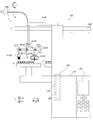
- the transport device 100 includes an air supply unit 1, a holding unit 2, a switching unit 3, a control unit 4, and a storage unit 5. Further, as shown in FIG. 2, the transfer device 100 is attached to the analyzer 200.
- the air supply unit 1 supplies air to a plurality of holding members 20 constituting a holding unit 2 described later via a flow path P.
- the air supply unit 1 includes, for example, a compressor that compresses and supplies air and a flow rate adjustment unit that adjusts a flow rate.
- the flow rate adjusting unit is, for example, a mass flow controller.
- the holding unit 2 has a plurality of holding members 20.
- the holding members 20 are a first holding member 21, a second holding member 22, and a third holding member 23.
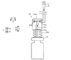
- the first holding member 21 includes a vacuum ejector 21 a that generates a vacuum, and a contact portion 21 b that contacts the surface of the holding target S.
- the vacuum ejector 21a has an inlet 21c through which air from the air supply unit 1 flows, an outlet 21d through which air having passed through the vacuum ejector 21a is discharged, and an opening 21f connected to a through hole 21e provided in the contact part 21b.
- the first holding member 21 sucks and holds the surface of the holding target S by the negative pressure generated by the air from the air supply unit 1.
- air from the air supply unit 1 passes through the vacuum ejector 21a, external air is sucked in from the opening 21f, and a negative pressure is generated.
- the object S to be held is sucked by the generated negative pressure, so that the object S to be held comes into contact with the contact portion 21b and is held.
- the first holding member 21 stops sucking air into the vacuum ejector 21a, and no negative pressure is generated. As a result, the holding state of the holding target S is released.
- the holding object S of the first holding member 21 is, for example, a sample container.
- the holding part 2 may have a plurality of first holding members 21 having different sizes of the contact part 21b. By providing a plurality, the first holding member 21 according to the size of the holding object S can be selected.
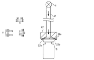
- the second holding member 22 has a bottom surface 22a facing the object S to be held, and an ejection port 22b provided on the bottom surface 22a for ejecting air.
- the second holding member 22 holds the upper surface of the holding target S in a non-contact state based on Bernoulli's theorem that the pressure decreases as the flow rate of the air increases, and a negative pressure is generated.
- the second holding member 22 jets the air supplied from the air supply unit 1 into a gap between the ejection port 22b and the holding target S, and holds the holding target S in a non-contact state.
- the second holding member 22 sends the air supplied from the air supply unit 1 obliquely from the upper surface to the side surface direction of the holding object S because the ejection port 22b is provided obliquely from the center to the outside. Gushing. When the supply of air from the air supply unit 1 is stopped, the negative pressure of the second holding member 22 disappears, and the holding state of the holding target S is released.
- the second holding member 22 holds the holding target S in a non-contact state. Therefore, it can be used for transporting the holding target S or the high-temperature holding target S whose contamination is desired to be prevented. Further, the second holding member 22 can hold the object to be held S even when the surface of the object S has irregularities.
- the holding target S is, for example, a sample or a component of the device.
- the holding unit 2 may include a plurality of second holding members 22 having different sizes of the bottom surface portion 22a facing the holding target S. By providing a plurality, the second holding member 22 according to the size of the holding target S can be selected.
- the third holding member 23 has an arm 23a sandwiching the holding target S, a spring 23b attached to the arm 23a, and an air cylinder 23c.
- the piston 23d in the air cylinder 23c is pushed by the air supplied from the air supply unit 1 to move the third holding member 23.
- the piston 23d is pressed by the pressure of the air supplied from the air supply unit 1, and the arm 23a is closed by the contraction of the spring 23b.
- the holding target S can be sandwiched by closing the arm 23a. Further, by stopping the supply of air from the air supply unit 1, the piston 23d returns to the original position as the spring 23b attempts to return to the original length. As a result, the arm 23a opens, and the holding state of the holding target S is released.
- the third holding member 23 includes a rotation drive mechanism 23e.
- the third holding member 23 rotates about a rotation axis extending in the Z direction by a rotation driving mechanism 23e.
- the rotation drive mechanism 23e is, for example, a motor.
- the third holding member 23 rotates the holding target S such as a container.
- a reader (not shown) may read the identification label attached to the holding target S.
- the third holding member 23 may be used to open and close the lid.
- the transport device 100 has a plurality of flow paths P between the air supply unit 1 and the holding member 20.
- the transport device 100 can change the air supply destination and change the holding member 20 to be used.
- the flow path P is provided to be long in order to move the holding member 20.
- the flow path P is made of, for example, Teflon (registered trademark), stainless steel, or the like.
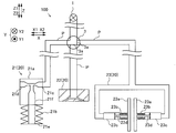
- the switching unit 3 includes a switching valve 3a that switches the flow path P.
- the switching valve 3 a connects the air supply unit 1 to the first holding member 21 or the second holding member 22 so that the flow path P Is a switchable three-way valve.
- the L-shaped flow path P rotates and switches the connection direction.
- the switching valve 3a is configured to switch the air supply unit 1 and the first holding member 21, the second holding member 22, or the It is a four-way valve configured to communicate one of the three holding members 23. As shown in FIG.
- the four-way valve opens the switching valve 3 a of the flow path P used among the first holding member 21, the second holding member 22, and the third holding member 23, and connects with the air supply unit 1. Then, the switching valve 3a of the flow path P with the other holding member 20 is closed and shut off.
- the control unit 4 selects a predetermined holding member 20 based on the content of work using the holding member 20, and performs control to switch to a flow path P corresponding to the selected holding member 20 by the switching valve 3a.
- the control unit 4 selects the first holding member 21 and controls the switching unit 3 to supply air to the first holding member 21. Switch to road P.
- the control unit 4 selects the second holding member 22 and controls the switching unit 3 to supply air to the second holding member 22. Switch to road P.
- the control unit 4 selects the third holding member 23 and controls the switching unit 3 to supply air to the third holding member 23. Switch to road P.
- the storage unit 5 is configured to store the work content using the holding member 20 and the holding member 20 to be used for one work selected from the plurality of holding members 20 in association with each other.
- the user previously programs the work procedure of the routine work in the storage unit 5, first selects a work using the first holding member 21, then selects a work using the second holding member 22, and finally selects a work using the second holding member 22. By selecting an operation using the third holding member 23, the operation is stored.
- operation 1 is an operation of opening the lid 203 of the analyzer 200.
- Operation 2 is an operation of taking out the glass liner 204 and replacing it with a new glass liner 204.
- Operation 3 is an operation of transporting a sample to be analyzed and putting it into the glass liner 204.
- Operation 4 is an operation of closing the lid 203 of the analyzer 200.
- the control unit 4 starts the work 2.
- the control unit 4 controls the switching valve 3a of the switching unit 3 so as to supply the air from the air supply unit 1 to the first holding member 21. Further, the control unit 4 controls the selection mechanism 8 so as to select the first holding member 21.
- the control unit 4 controls the horizontal movement mechanism 6 so that the first holding member 21 is horizontally moved so as to be directly above the vaporization chamber 202. Then, the control section 4 controls the vertical movement mechanism 7 to lower the first holding member 21. As shown in FIG. 12, after the first holding member 21 holds the glass liner 204, the control unit 4 performs control to raise the vertical movement mechanism 7.
- the control unit 4 controls the horizontal moving mechanism 6 to convey the glass liner 204 to a waste box (not shown), and moves the first holding member 21.
- the control unit 4 performs control to stop the supply of air from the air supply unit 1 to the first holding member 21 after the first holding member 21 moves onto the waste box. As a result, the glass liner 204 is separated from the first holding member 21 and is discarded in a waste box.
- the control unit 4 controls the switching valve 3a of the switching unit 3 to supply the air from the air supply unit 1 to the third holding member 23. Further, the control unit 4 controls the selection mechanism 8 so as to select the third holding member 23. Next, the control unit 4 controls the horizontal movement mechanism 6 so as to horizontally move the third holding member 23 directly above the lid 203 of the analyzer 200. Then, as shown in FIG. 14, the control unit 4 controls the vertical movement mechanism 7 to lower the third holding member 23. Thus, the lid 203 held by the third holding member 23 is placed in the vaporization chamber 202. The control unit 4 rotates the third holding member 23 and controls the vertical movement mechanism 7 to close the lid 203. Finally, the control unit 4 performs control to stop supply of air from the air supply unit 1 to the third holding member 23. Thus, the operation 4 is completed.
- the transport device 100 includes the holding unit having the plurality of holding members 20 including the air supply unit 1, the first holding member 21, and the second holding member 22, as described above. 2 and a switching unit 3 for switching the air supply destination from the air supply unit 1 to a first holding member 21 and a second holding member 22. Accordingly, by switching the supply destination from the air supply unit 1 by the switching unit 3, it is possible to switch the holding member 20 in accordance with the holding target S without stopping the transfer device 100. Therefore, the holding unit 2 suitable for the holding target S can be easily changed without interrupting the work (holding and holding of the holding target).
- the transport device 100 further includes a rotation drive mechanism 23e that rotates the arm 23a of the third holding member 23.
- a rotation drive mechanism 23e that rotates the arm 23a of the third holding member 23.
- a plurality of flow paths P for supplying air from the air supply unit 1 to the plurality of holding members 20 are further provided, and the switching unit 3 includes a switching valve 3a for switching the flow path P.
- the switching unit 3 includes a switching valve 3a for switching the flow path P.
- the transport device 100 selects a predetermined holding member 20 from the plurality of holding members 20 based on the information of the work content using the holding member 20, and
- the control unit 4 further includes a control unit 4 configured to perform control of switching to the flow path P corresponding to the member 20 by the switching valve 3a.
- the control unit 4 switches the switching valve 3a, whereby air is supplied to the selected holding member 20, and the holding member 20 can be switched. As a result, the operation using the plurality of holding members 20 can be performed continuously.
- the storage unit in which the work content using the holding member 20 and the holding member 20 to be used for one work selected from the plurality of holding members 20 are stored in association with each other.
- the control unit 4 further selects the predetermined holding member 20 from the plurality of holding members 20 based on the information of the work content using the holding member 20 stored in the storage unit 5, and selects the predetermined holding member 20. It is configured to perform control to switch to the flow path P corresponding to the holding member 20 by the switching valve 3a. In this way, the control unit 4 can switch the holding member 20 for each work content stored in the storage unit 5.
- the operation using the plurality of holding members 20 can be automatically performed by storing the operation using the plurality of holding members 20 in advance.
- the first holding member 21 is used for holding and transporting the sample container
- the second holding member 22 is used for holding and transporting the sample. It is configured to: In this case, the holding target S that can be transferred in a contact state, such as a sample container, is transferred using the first holding member 21, and the holding target S that needs to avoid contamination, such as a sample, is placed in the second holding member 21.
- the holding member 22 can be used to carry the sheet in a non-contact state.
- the horizontal moving mechanism 6 that integrally moves the plurality of holding members 20 included in the holding unit 2 and the plurality of holding members 20 included in the holding unit 2 in the vertical direction.
- a vertical movement mechanism 7 for individually moving.
- the plurality of holding members 20 can be simultaneously moved in the horizontal direction, and the holding members 20 to be used can be moved in the vertical direction.
- only the holding member 20 to be used can be brought close to the holding object S, so that holding of the holding object S by another unused holding member 20 can be suppressed.
- the selection mechanism 8 for selecting the holding member 20 to be vertically moved is further provided, and the vertical movement mechanism 7 is configured to lower the holding member 20 selected by the selection mechanism 8. It is configured. In this way, the holding member 20 corresponding to the holding target S can be reliably selected and used.
- the holding member 20 may include a fourth holding member of a magnet type.
- the rotation drive mechanism 23e is a motor
- the present invention is not limited to this.
- the rotation drive mechanism 23e may be configured to rotate using air from the air supply unit 1.
- the switching unit 3 includes the three-way valve or the four-way valve has been described, but the present invention is not limited to this.
- the switching unit 3 may provide an on-off valve in the flow path P connected to each holding member 20.
- the method of controlling the flow path P of the three-way valve and the four-way valve is not particularly limited as long as it is a commonly used method.
- the present invention is not limited to this.
- the second holding member 22 or the third holding member 23 may carry the glass liner 204.
- the present invention is not limited to this.
- the transport device 100 includes a sample suction / discharge unit
- the sample container is transported using the second holding member 22 or the third holding member 23, and the sample is charged using the sample suction / discharge unit. Is also good.
- the transport device 100 is used for gas chromatography
- the present invention is not limited to this.
- it may be used for another analyzer 200 such as liquid chromatography.
- the vertical movement mechanism 7 may have any configuration as long as the holding member 20 can be moved in the vertical direction.
- the vertical movement mechanism 7 may be configured by, for example, a ball screw mechanism or a belt and pulley mechanism.
- the selection mechanism 8 is circular, but the present invention is not limited to this.
- it may be a polygon such as a triangle or a quadrangle.
- the holding member 20 may be arranged at the vertex.
Landscapes
- Engineering & Computer Science (AREA)
- Mechanical Engineering (AREA)
- Robotics (AREA)
- Manipulator (AREA)
- Automatic Analysis And Handling Materials Therefor (AREA)
- Container, Conveyance, Adherence, Positioning, Of Wafer (AREA)
Abstract
この搬送装置(100)は、空気供給部(1)と、第1保持部材(21)と第2保持部材(22)とを含む複数の保持部材(20)を有する保持部(2)と、空気供給部(1)からの空気の供給先を、第1保持部材(21)と、第2保持部材(22)とに切り替える切替部(3)とを備える。
Description
本発明は、搬送装置に関する。
従来、試料容器(保持対象物)を搬送する搬送装置が知られている。従来の搬送装置の例としては、たとえば、特開2003-95430号公報に開示されている。
上記特開2003-95430号公報に開示されている搬送装置は、圧縮空気を供給する圧縮空気源を備え、圧縮空気源から圧縮空気をエジェクタに供給することによって真空を発生させ、吸着カップに保持対象物を吸着し搬送している。
また、特開2017-112255号公報に開示されている搬送装置は、ガスを噴出することにより負圧を生成し、非接触状態で保持対象物を吸引保持するベルヌーイの原理を利用した保持パッドによって非接触状態で保持対象物を搬送している。
しかしながら、保持対象物によって適している保持部が異なるが、特開2003-95430号公報に記載された搬送装置および特開2017-112255号公報に記載された搬送装置の保持部は、複数種類の保持対象物に対応していない。そのため、保持対象物に合わせて、ユーザは適した保持部に取り換える(切り替える)必要がある。また、保持部を取り替える(切り替える)ためにユーザは搬送装置を止める必要があり、そのたびに搬送装置を停止させ作業を中断する必要がある。
この発明は、上記のような課題を解決するためになされたものであり、この発明の1つの目的は、装置を停止させることなく保持対象物に適した保持部に切り替えることが可能な搬送装置を提供することである。
上記目的を達成するために、この発明の一の局面における搬送装置は、空気を供給する空気供給部と、空気供給部からの空気によって発生した負圧によって保持対象物の表面を吸着して保持する第1保持部材と、空気供給部から供給された空気を噴出口と保持対象物との隙間に噴出して非接触状態で保持対象物を保持する第2保持部材とを含む複数の保持部材を有する保持部と、空気供給部からの空気の供給先を、第1保持部材と、第2保持部材とに切り替える切替部と、を備える。
この発明の一の局面における搬送装置は、上記のように、空気供給部と、第1保持部材と、第2保持部材とを含む複数の保持部材を有する保持部と、空気供給部からの空気の供給先を、第1保持部材と、第2保持部材とに切り替える切替部とを備える。これにより、切替部によって空気供給部からの供給先を切り替えることにより、装置を停止させることなく保持対象物に合わせて保持部材を切り替えることが可能となる。そのため、作業(保持対象物の保持作業および搬送作業)を中断することなく、保持対象物に適した保持部を容易に替えることができる。
上記一の局面における搬送装置において、好ましくは、複数の保持部材は、第1保持部材および第2保持部材に加えて、空気供給部から供給された空気の空気圧によって開閉するアームを有する第3保持部材をさらに含む。このように構成すれば、保持対象物の保持に用いる保持部材の選択肢が増えるため、保持対象物の適用範囲を拡大することができる。
この場合、好ましくは、搬送装置は、第3保持部材のアームを回転させる回転駆動機構をさらに備える。このように構成すれば、たとえば、保持対象物に蓋が設けられている場合に、アームを回転させることによって、蓋を開閉することが可能となる。
上記一の局面における搬送装置において、好ましくは、空気供給部からの空気を複数の保持部材にそれぞれ供給する複数の流路をさらに備え、切替部は、流路を切り替える切替弁を含む。このように構成すれば、切替弁を用いて流路を切り替えることにより、保持部材を保持対象物に合わせて容易に切り替えることができる。
この場合、好ましくは、搬送装置は、保持部材を用いる作業内容の情報に基づいて、複数の保持部材から所定の保持部材を選択するとともに、選択された保持部材に対応する流路に切替弁によって切り替える制御を行うように構成されている制御部をさらに備える。このように構成すれば、制御部が切替弁を切り替えることにより、選択された保持部材に空気が供給され、保持部材を切り替えることが可能となる。その結果、複数の保持部材を用いる作業を連続して行うことが可能となる。
この場合、好ましくは、保持部材を用いた作業内容と、複数の保持部材から選択された1つの作業に使用すべき保持部材とが関連付けて記憶される記憶部をさらに備え、制御部は、記憶部に記憶された保持部材を用いた作業内容の情報に基づいて、複数の保持部材から所定の保持部材を選択するとともに、選択された保持部材に対応する流路に切替弁によって切り替える制御を行うように構成されている。このように構成すれば、記憶部に記憶された作業内容毎に、制御部が保持部材を切り替えることが可能となる。その結果、予め複数の保持部材を用いる作業を記憶させることにより、複数の保持部材を用いる作業を自動的に行うことができる。
この場合、好ましくは、第1保持部材は、試料容器を保持し、搬送する作業に使用され、第2保持部材は、試料を保持し、搬送する作業に使用されるように構成されている。このように構成すれば、試料容器のように接触状態で搬送できる保持対象物は、第1保持部材を用いて搬送し、試料のようにコンタミネーションを避ける必要がある保持対象物は、第2保持部材を用いて非接触状態で搬送することができる。
上記一の局面における搬送装置において、好ましくは、保持部が有する複数の保持部材を一体的に移動させる水平方向移動機構と、垂直方向において、保持部が有する複数の保持部材を個別に移動させる垂直方向移動機構と、をさらに備える。このように構成すれば、複数の保持部材を同時に水平方向に移動させることができるとともに、使用する保持部材を垂直方向に移動させることができる。この結果、使用する保持部材だけを保持対象物に近づけることができるため、別の使用しない保持部材に保持対象物が保持されることを抑制することができる。
この場合、好ましくは、垂直移動させる保持部材を選択する選択機構をさらに備え、垂直方向移動機構は、選択機構において選択された保持部材を下降させるように構成されている。このように構成すれば、保持対象物に対応した保持部材を確実に選択して使用することができる。
本発明によれば、上記のように、装置を停止させることなく保持対象物に適した保持部に切り替えることが可能な搬送装置を提供することができる。
以下、本発明を具体化した実施形態を図面に基づいて説明する。
図1~図14を参照して、ガスクロマトグラフィーに用いる場合を例に本発明の実施形態による搬送装置100の構成について説明する。
図1に示すように、搬送装置100は、空気供給部1と、保持部2と、切替部3と、制御部4と、記憶部5とを備える。また、図2に示すとおり、搬送装置100は、分析装置200に取り付けられる。
図1に示すように、空気供給部1は、流路Pを介して後述する保持部2を構成する複数の保持部材20に空気を供給する。空気供給部1は、たとえば、空気を圧縮し、供給するコンプレッサーと、流量を調整する流量調整部とを含む。流量調整部は、たとえばマスフローコントローラである。
保持部2は、複数の保持部材20を有する。保持部材20は、第1保持部材21、第2保持部材22、および第3保持部材23である。
図3に示すように、第1保持部材21は、真空を発生させる真空エジェクタ21aと、保持対象物Sの表面と接触する接触部21bとを備える。真空エジェクタ21aは、空気供給部1からの空気が流入する入口21cと、真空エジェクタ21a内を通過した空気が排出される出口21dと、接触部21bに設けられた貫通孔21eと繋がる開口部21fとを備える。第1保持部材21は、空気供給部1からの空気によって発生した負圧によって保持対象物Sの表面を吸着して保持する。空気供給部1からの空気が真空エジェクタ21a内を通過することにより、開口部21fから外部の空気が吸い込まれ、負圧が発生する。発生した負圧により保持対象物Sが吸引されることによって、接触部21bに保持対象物Sが接触し、保持される。第1保持部材21は、空気供給部1からの空気の供給を止めることにより、真空エジェクタ21a内への空気の吸引が止まり、負圧が発生しなくなる。その結果、保持対象物Sの保持状態が解除される。第1保持部材21の保持対象物Sは、たとえば試料容器である。
保持部2は、接触部21bの大きさの異なる第1保持部材21を複数有していてもよい。複数設けることにより保持対象物Sの大きさに即した第1保持部材21を選択することができる。
図4に示すように、第2保持部材22は、保持対象物Sと対向する底面部22aと、底面部22aに設けられた空気を噴出する噴出口22bとを有する。第2保持部材22は、空気の流速が速いほど圧力が下がり負圧が発生するというベルヌーイの定理に基づいて保持対象物Sの上面を非接触状態で保持する。第2保持部材22は、空気供給部1から供給された空気を噴出口22bと保持対象物Sとの隙間に噴出して非接触状態で保持対象物Sを保持する。第2保持部材22は、空気供給部1から供給された空気を噴出口22bが中央から外側に向かって斜めに設けられているため、空気を保持対象物Sの上面から側面方向にかけて斜め方向に噴出する。第2保持部材22は、空気供給部1からの空気の供給を止めることにより負圧が消滅し、保持対象物Sの保持状態が解除される。
第2保持部材22は、第1保持部材21と異なり非接触状態で保持対象物Sを保持する。そのため、汚染を防ぎたい保持対象物Sや高温の保持対象物Sを搬送するために用いることができる。また、第2保持部材22は、保持対象物Sの表面に凹凸がある場合でも保持することができる。保持対象物Sは、たとえば、試料あるいは、装置の部品である。
保持部2は、保持対象物Sと対向する底面部22aの大きさの異なる第2保持部材22を複数有していてもよい。複数設けることにより保持対象物Sの大きさに即した第2保持部材22を選択することができる。
図5に示すように、第3保持部材23は、保持対象物Sを挟むアーム23aとアーム23aに取り付けられたバネ23bとエアシリンダ23cとを有する。第3保持部材23は、空気供給部1から供給された空気によってエアシリンダ23c内のピストン23dが押され移動する。空気供給部1から供給された空気の圧力によりピストン23dが押されるとともに、バネ23bが縮むことによってアーム23aを閉じる。アーム23aを閉じることにより保持対象物Sを挟むことができる。また、空気供給部1からの空気の供給を止めることにより、バネ23bが元の長さに戻ろうとすることに伴ってピストン23dが元の位置に戻る。その結果、アーム23aが開き、保持対象物Sの保持状態が解除される。
第3保持部材23は、回転駆動機構23eを備える。第3保持部材23は、回転駆動機構23eによってZ方向に延びた回転軸を中心に回転する。回転駆動機構23eは、たとえば、モータである。回転駆動機構23eによって、第3保持部材23は容器等の保持対象物Sを回転させる。保持対象物Sを回転させることにより、たとえば、図示しない読取機が、保持対象物Sに付された識別ラベルを読取ってもよい。また、蓋を開閉するために第3保持部材23を用いてもよい。
図6および図7に示すように、搬送装置100は、空気供給部1と保持部材20との間に複数の流路Pが設けられている。搬送装置100は、流路Pを切替部3によって切り替えることにより、空気の供給先が切り替わり使用する保持部材20を変更することができる。流路Pは、保持部材20を移動させるために長めに設けられる。流路Pは、たとえば、テフロン(登録商標)、ステンレスなどで構成されている。
切替部3は、流路Pを切り替える切替弁3aを含む。第1保持部材21および第2保持部材22を有する搬送装置100の場合に、切替弁3aは、空気供給部1と第1保持部材21または第2保持部材22とを接続するように流路Pが切替可能な三方弁である。図6に示すように、たとえば、三方弁は、L字形の流路Pが回転し、接続方向を切り替える。また、第1保持部材21、第2保持部材22および第3保持部材23を有する搬送装置100の場合に切替弁3aは、空気供給部1と第1保持部材21、第2保持部材22または第3保持部材23のうちの1つを連絡するように構成されている四方弁である。図7に示すように、たとえば、四方弁は、第1保持部材21、第2保持部材22および第3保持部材23のうち使用する流路Pの切替弁3aを開き、空気供給部1と接続し、他の保持部材20との流路Pの切替弁3aを閉じて遮断する。
制御部4は、保持部材20を用いる作業内容に基づいて、所定の保持部材20を選択するとともに、選択された保持部材20に対応する流路Pに切替弁3aよって切り替える制御を行う。第1保持部材21を用いて試料容器を搬送する場合に、制御部4は、第1保持部材21を選択するとともに、切替部3を制御して、第1保持部材21に空気を供給する流路Pに切り替える。また、第2保持部材22を用いて試料を搬送する場合に、制御部4は、第2保持部材22を選択するとともに、切替部3を制御して第2保持部材22に空気を供給する流路Pに切り替える。さらに、第3保持部材23を用いて試料を搬送する場合に、制御部4は、第3保持部材23を選択するとともに、切替部3を制御して第3保持部材23に空気を供給する流路Pに切り替える。
記憶部5は、保持部材20を用いた作業内容と、複数の保持部材20から選択された1つの作業に使用すべき保持部材20とを関連付けて記憶されるように構成されている。ユーザは、予め記憶部5にルーチン作業の作業手順をプログラミングしておき、まず、第1保持部材21を用いる作業を選択し、次に、第2保持部材22を用いる作業を選択し、最後に第3保持部材23を用いる作業を選択することにより記憶させる。
ここで、図2に示すように、分析装置200は、分析結果を表示する表示部201と、気化室202と、気化室202を密封する蓋部203と、気化室内に挿入されるガラスライナー204とを備える。分析装置200は、ガラスライナー204の中に投入された試料を加熱し気化させ、気化したガスに含まれる成分を分析するように構成されている。
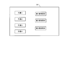
図8に示すとおり、分析装置200の表示部201には、例えば、予めプログラミングしておいた作業と、第1保持部材21、第2保持部材22および第3保持部材23が画面に表示される。そして、ユーザが、各保持部材20(第1保持部材21、第2保持部材22および第3保持部材23)に対して、保持部材20を使用する作業を選択することにより記憶部5に作業内容と保持部材20とを関連付けて記憶させる。
図2に示すように、搬送装置100はさらに、保持部材20を移動するために水平方向移動機構6と垂直方向移動機構7と選択機構8とを備える。
図2および図9に示すように、水平方向移動機構6は、保持部材20を一体的にX方向に移動させる第1方向移動機構6aと保持部材20を一体的にY方向に移動させる第2方向移動機構6bとを有している。ここで、Z方向は、垂直方向移動機構7が移動する方向を表す。X方向は、試料を置くトレーTと分析装置200とが平面内で並ぶ方向である。Y方向は水平面内でX方向と直交する方向である。水平方向移動機構6は、制御部4によってXY座標の情報を元に移動する。
具体的には、第1方向移動機構6aは、第2方向移動機構6bの一端側(Y2側)を保持している。第1方向移動機構6aは、たとえば、ボールねじ機構または、ラックアンドピニオン機構などの直動機構を含む。
第2方向移動機構6bは、第1保持部材21と、第2保持部材22と、第3保持部材23とをY方向に移動するように構成されている。保持部材20は、第2方向移動機構6bの搬送装置100のトレーT側に設けられている。第2方向移動機構6bは、たとえば、ボールねじ機構または、ラックアンドピニオン機構などの直動機構を含む。
図10に示すように、垂直方向移動機構7は、第1保持部材21、第2保持部材22および第3保持部材23にそれぞれ設けられている。具体的には、垂直方向移動機構7は、後述する選択機構8において選択された保持部材20を下降させるように構成されている
垂直方向移動機構7は、移動部7aと駆動部7bとを含む。移動部7aの一端側には保持部材20が設けられており、他端側にはラックが形成されている。垂直方向移動機構7は、駆動部7bによってピニオンを回動させることにより、保持部材20を垂直方向に移動するように構成されている。垂直方向移動機構7は、いわゆるラックアンドピニオン機構である。
図10に示すように選択機構8は、垂直方向移動機構7が取り付けられる第1取付部8aと、水平方向移動機構6に取り付けられる第2取付部8bと第2取付部8bに取り付けられた回転部8cを備える。第1取付部8aは、たとえば、円形形状を有する。図10では、模式的に保持部材20を横一列に並べて記載しているが、保持部材20は、第1取付部8aの円周状に等間隔に並べて取り付けられている。第2取付部8bは、水平方向移動機構6に取り付けられ固定される部分と回転部8cの回転軸として回転する部分とからなる。回転部8cは、たとえばモータである。回転部8cによって、選択された保持部材20は、保持対象物Sと対向するように配置される。
ここで、本発明に係る搬送装置100を作業に用いる例について説明する。まず、作業1は、分析装置200の蓋部203を開ける作業である。作業2は、ガラスライナー204を取り出し、新しいガラスライナー204と交換する作業である。作業3は、分析する試料を搬送し、ガラスライナー204に投入する作業である。作業4は、分析装置200の蓋部203を閉める作業である。
まず、ユーザの操作によって、記憶部5は、一連の作業と、保持部材20とを関連付けて記憶する。本実施形態では、ユーザが、作業1および作業4に第3保持部材23を選択し、作業2には第2保持部材22を選択し、作業3には第1保持部材21を選択したとする。
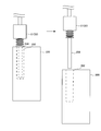
ユーザが、作業を開始するように搬送装置100を操作すると、制御部4は、空気供給部1からの空気を第3保持部材23に供給するように切替部3の切替弁3aの制御を行う。また、制御部4は、第3保持部材23を選択するように選択機構8の制御を行う。次に、制御部4は、第3保持部材23を分析装置200の蓋部203の真上に水平移動させるために水平方向移動機構6の制御を行う。そして、制御部4は、垂直方向移動機構7を制御し、第3保持部材23を下降させる。さらに、制御部4は、空気供給部1から第3保持部材23へ空気を供給することによりアーム23aを閉じる制御を行う。図11に示すように、アーム23aを閉じることにより第3保持部材23が蓋部203を保持したあと、制御部4は、第3保持部材23を回転させるとともに垂直方向移動機構7を上昇させる制御を行う。以上で作業1が終了する。
作業1が終了すると、制御部4は、作業2を開始する。制御部4は、空気供給部1からの空気を第1保持部材21に供給するように切替部3の切替弁3aの制御を行う。また、制御部4は、第1保持部材21を選択するように選択機構8の制御を行う。次に、制御部4は、第1保持部材21が気化室202の真上に来るように水平移動させるように水平方向移動機構6の制御を行う。そして、制御部4は、垂直方向移動機構7を制御し、第1保持部材21を下降させる。図12に示すように、制御部4は、第1保持部材21がガラスライナー204を保持した後に、垂直方向移動機構7を上昇させる制御を行う。
さらに、制御部4は、ガラスライナー204を廃棄箱(図示せず)へと搬送するように水平方向移動機構6を制御し、第1保持部材21を移動させる。制御部4は、第1保持部材21が廃棄箱の上に移動した後に、空気供給部1から第1保持部材21への空気の供給を止める制御を行う。これによりガラスライナー204が第1保持部材21から離れ、廃棄箱に廃棄される。
そして、制御部4は、作業3を開始する。制御部4は、第1保持部材21を新しいガラスライナー204が置いてある場所へと移動させるように水平方向移動機構6の制御を行う。次に、制御部4は、垂直方向移動機構7を制御し、第1保持部材21を下降させる。そして、制御部4は、第1保持部材21がガラスライナー204を保持した後に、垂直方向移動機構7を上昇させる制御を行う。
制御部4は、ガラスライナー204を気化室202へと搬送するように水平方向移動機構6の制御を行う。そして、制御部4は、垂直方向移動機構7を制御し、第1保持部材21を下降させる。そして、第1保持部材21からガラスライナー204を離すために、制御部4は、空気供給部1からの空気の供給を止める制御を行う。それにより、ガラスライナー204は、気化室202に挿入される。以上で作業2が終了する。
作業2が終了すると、制御部4は、作業3を開始する。まず、制御部4は、空気供給部1からの空気を第2保持部材22に供給するように切替部3の切替弁3aの制御を行う。また、制御部4は、第2保持部材22を選択するように選択機構8の制御を行う。次に、制御部4は、第2保持部材22を試料S1が置いてある場所に水平移動させるために、水平方向移動機構6の制御を行う。そして、制御部4は、垂直方向移動機構7を制御し、第2保持部材22を下降させる。第2保持部材22が試料S1を保持した後に、制御部4は、垂直方向移動機構7を上昇させる制御を行う。
さらに、図13に示すように、制御部4は、試料S1をガラスライナー204へと搬送するように水平方向移動機構6の制御を行う。そして、制御部4は、垂直方向移動機構7を制御し、第2保持部材22を下降させる。そして、第2保持部材22から試料S1を離すために、制御部4は、空気供給部1からの空気の供給を止める制御を行う。それにより、試料S1は、気化室202に投入される。以上で作業3が終了する。
作業3が終了すると、制御部4は、空気供給部1からの空気を第3保持部材23に供給するように切替部3の切替弁3aの制御を行う。また、制御部4は、第3保持部材23を選択するように選択機構8の制御を行う。次に、制御部4は、第3保持部材23を分析装置200の蓋部203の真上に水平移動させるように水平方向移動機構6の制御を行う。そして、図14に示すように、制御部4は、垂直方向移動機構7を制御し、第3保持部材23を下降させる。それにより、第3保持部材23が保持している蓋部203が気化室202に載置される。制御部4は、第3保持部材23を回転させるとともに垂直方向移動機構7を制御し、蓋部203を閉める。最後に、制御部4は、空気供給部1から第3保持部材23への空気の供給を止める制御を行う。以上で作業4が終了する。
なお、分析装置200が蓋部自動開閉機構を備える場合は、作業1および作業4は行わない。また、作業2は、他の作業よりも頻繁に行なう必要がないため、作業1から作業4まで行った後は、作業1、作業3、作業4を繰り返してもよい。また、分析装置200が蓋部自動開閉機構を備える場合は、作業2、作業3のあと作業3を繰り返して行ってもよい。
(本実施形態の効果)
本実施形態では、以下のような効果を得ることができる。
本実施形態では、以下のような効果を得ることができる。
本実施形態では、上記のように、搬送装置100は、上記のように、空気供給部1と、第1保持部材21と、第2保持部材22とを含む複数の保持部材20を有する保持部2と、空気供給部1からの空気の供給先を、第1保持部材21と、第2保持部材22とに切り替える切替部3とを備える。これにより、切替部3によって空気供給部1からの供給先を切り替えることにより、搬送装置100を停止させることなく保持対象物Sに合わせて保持部材20を切り替えることが可能となる。そのため作業(保持対象物の保持作業および搬送作業)を中断することなく、保持対象物Sに適した保持部2を容易に替えることができる。
また、本実施形態では、上記のように、複数の保持部材20は、第1保持部材21および第2保持部材22に加えて、空気供給部1から供給された空気の空気圧によって開閉するアーム23aを有する第3保持部材23をさらに含む。このようにすれば、保持対象物Sの保持に用いる保持部材20の選択肢が増えるため、保持対象物Sの適用範囲を拡大することができる。
また、本実施形態では、搬送装置100は、第3保持部材23のアーム23aを回転させる回転駆動機構23eをさらに備える。こうすれば、たとえば、保持対象物Sに蓋が設けられている場合に、アーム23aを回転させることによって、蓋を開閉することが可能となる。
また、本実施形態では、空気供給部1からの空気を複数の保持部材20にそれぞれ供給する複数の流路Pをさらに備え、切替部3は、流路Pを切り替える切替弁3aを含む。こうすれば、切替弁3aを用いて流路Pを切り替えることにより、保持部材20を保持対象物Sに合わせて容易に切り替えることができる。
また、本実施形態では、上記のように、搬送装置100は、保持部材20を用いる作業内容の情報に基づいて、複数の保持部材20から所定の保持部材20を選択するとともに、選択された保持部材20に対応する流路Pに切替弁3aによって切り替える制御を行うように構成されている制御部4をさらに備える。こうすれば、制御部4が切替弁3aを切り替えることにより、選択された保持部材20に空気が供給され、保持部材20を切り替えることが可能となる。その結果、複数の保持部材20を用いる作業を連続して行うことが可能となる。
また、本実施形態では、上記のように、保持部材20を用いた作業内容と、複数の保持部材20から選択された1つの作業に使用すべき保持部材20とが関連付けて記憶される記憶部5をさらに備え、制御部4は、記憶部5に記憶された保持部材20を用いた作業内容の情報に基づいて、複数の保持部材20から選所定の保持部材20を選択するとともに、選択された保持部材20に対応する流路Pに切替弁3aによって切り替える制御を行うように構成されている。こうすれば、記憶部5に記憶された作業内容毎に、制御部4が保持部材20を切り替えることが可能となる。その結果、予め複数の保持部材20を用いる作業を記憶させることにより、複数の保持部材20を用いる作業を自動的に行うことができる。
また、本実施形態では、上記のように、第1保持部材21は、試料容器を保持し、搬送する作業に使用され、第2保持部材22は、試料を保持し、搬送する作業に使用されるように構成されている。こうすれば、試料容器のように接触状態で搬送できる保持対象物Sは、第1保持部材21を用いて搬送し、試料のようにコンタミネーションを避ける必要がある保持対象物Sは、第2保持部材22を用いて非接触状態で搬送することができる。
また、本実施形態では、上記のように、保持部2が有する複数の保持部材20を一体的に移動させる水平方向移動機構6と、垂直方向において、保持部2が有する複数の保持部材20を個別に移動させる垂直方向移動機構7と、をさらに備える。こうすれば、複数の保持部材20を同時に水平方向に移動させることができるとともに、使用する保持部材20を垂直方向に移動させることができる。この結果、使用する保持部材20だけを保持対象物Sに近づけることができるため、別の使用しない保持部材20に保持対象物Sが保持されることを抑制することができる。
また、本実施形態では、上記のように、垂直移動させる保持部材20を選択する選択機構8をさらに備え、垂直方向移動機構7は、選択機構8において選択された保持部材20を下降させるように構成されている。こうすれば、保持対象物Sに対応した保持部材20を確実に選択して使用することができる。
(変形例)
なお、今回開示された実施形態は、すべての点で例示であって制限的なものではないと考えられるべきである。本発明の範囲は、上記した実施形態の説明ではなく、特許請求の範囲によって示され、さらに特許請求の範囲と均等の意味および範囲内でのすべての変更(変形例)が含まれる。
なお、今回開示された実施形態は、すべての点で例示であって制限的なものではないと考えられるべきである。本発明の範囲は、上記した実施形態の説明ではなく、特許請求の範囲によって示され、さらに特許請求の範囲と均等の意味および範囲内でのすべての変更(変形例)が含まれる。
たとえば、上記実施形態では、保持部材20が、第1保持部材21、第2保持部材22および第3保持部材23を含む例を示したが、本発明はこれに限られない。たとえば、保持部材20が、マグネット方式の第4保持部材を備えていてもよい。
また、上記実施形態では、回転駆動機構23eがモータである例を示したが、本発明はこれに限られない。たとえば、回転駆動機構23eは、空気供給部1からのエアを利用して回転させるように構成されていてもよい。
また、上記実施形態では、切替部3が、三方弁または四方弁を含む例を示したが、本発明はこれに限られない。たとえば、切替部3は、各保持部材20に接続する流路Pに開閉弁を設けてもよい。また、三方弁および四方弁の流路Pの制御方法は、一般的に用いられる方法であれば特に限定されない。
また、上記実施形態では、第1保持部材21がガラスライナー204を搬送する例を示したが、本発明はこれに限られない。たとえば、第2保持部材22または第3保持部材23がガラスライナー204を搬送してもよい。
また、上記実施形態では、第3保持部材23が試料を分析装置200に投入する例を示したが、本発明はこれに限られない。たとえば、搬送装置100が、試料吸引吐出部を備えている場合は、第2保持部材22または第3保持部材23を用いて試料容器を搬送し、試料吸引吐出部を用いて試料を投入してもよい。
また、上記実施形態では、搬送装置100をガスクロマトグラフィーに使用する例を示したが、本発明はこれに限られない。たとえば、液体クロマトグラフィーのような他の分析装置200に用いてもよい。
また、上記実施形態では、搬送装置100を試料分析に用いる例を示したが、本発明はこれに限られない。たとえば、複数の部品からなる製品を作る製造ラインに用いてもよい。
また、上記実施形態では、垂直方向移動機構7がラックアンドピニオン機構によって保持部材20を垂直方向に移動させる構成の例を示したが、本発明はこれに限られない。保持部材20を垂直方向に移動させることが可能であれば、垂直方向移動機構7はどのように構成されていてもよい。垂直方向移動機構7は、たとえば、ボールねじ機構またはベルトアンドプーリー機構で構成されていてもよい。
また、上記実施形態では、選択機構8が円形である例を示したが、本発明はこれに限られない。たとえば、三角形、四角形などの多角形であってもよい。この場合、保持部材20は、頂点に配置してもよい。
1 空気供給部
2 保持部
3 切替部
4 制御部
5 記憶部
6 水平方向移動機構
7 垂直方向移動機構
8 選択機構
20 保持部材
21 第1保持部材
22 第2保持部材
23 第3保持部材
100 搬送装置
2 保持部
3 切替部
4 制御部
5 記憶部
6 水平方向移動機構
7 垂直方向移動機構
8 選択機構
20 保持部材
21 第1保持部材
22 第2保持部材
23 第3保持部材
100 搬送装置
Claims (9)
- 空気を供給する空気供給部と、
前記空気供給部からの空気によって発生した負圧によって保持対象物の表面を吸着して保持する第1保持部材と、前記空気供給部から供給された空気を前記保持対象物との隙間に噴出して非接触状態で前記保持対象物を保持する第2保持部材とを含む複数の保持部材を有する保持部と、
前記空気供給部からの空気の供給先を、前記第1保持部材と、前記第2保持部材とに切り替える切替部と、を備える、搬送装置。 - 複数の前記保持部材は、前記第1保持部材および前記第2保持部材に加えて、前記空気供給部から供給された空気の空気圧によって開閉するアームを有する第3保持部材をさらに含む、請求項1に記載の搬送装置。
- 前記第3保持部材のアームを回転させる回転駆動機構をさらに備える、請求項2に記載の搬送装置。
- 前記空気供給部からの空気を複数の前記保持部材にそれぞれ供給する複数の流路をさらに備え、
前記切替部は、前記流路を切り替える切替弁を含む、請求項1~3のいずれか1項に記載の搬送装置。 - 前記保持部材を用いる作業内容の情報に基づいて、複数の前記保持部材から所定の前記保持部材を選択するとともに、選択された前記保持部材に対応する前記流路に前記切替弁によって切り替える制御を行うように構成されている制御部をさらに備える、請求項4に記載の搬送装置。
- 前記保持部材を用いた作業内容と、複数の前記保持部材から選択された1つの作業に使用すべき前記保持部材とが関連付けて記憶される記憶部をさらに備え、
前記制御部は、前記記憶部に記憶された前記保持部材を用いた作業内容の情報に基づいて、複数の前記保持部材から選所定の前記保持部材を選択するとともに、選択された前記保持部材に対応する前記流路に前記切替弁によって切り替える制御を行うように構成されている、請求項5に記載の搬送装置。 - 前記第1保持部材は、試料容器を保持し、搬送する作業に使用され、前記第2保持部材は、試料を保持し、搬送する作業に使用されるように構成されている、請求項5または6に記載の搬送装置。
- 水平方向において、前記保持部が有する複数の前記保持部材を一体的に移動させる水平方向移動機構と、
垂直方向において、前記保持部が有する複数の前記保持部材を個別に移動させる垂直方向移動機構と、をさらに備える、請求項1~7のいずれか1項に記載の搬送装置。 - 垂直移動させる前記保持部材を選択する選択機構をさらに備え、
前記垂直方向移動機構は、前記選択機構において選択された前記保持部材を下降させるように構成されている、請求項8に記載の搬送装置。
Priority Applications (3)
| Application Number | Priority Date | Filing Date | Title |
|---|---|---|---|
| JP2020535358A JP7173148B2 (ja) | 2018-08-06 | 2018-08-06 | クロマトグラフ用の試料容器搬送装置 |
| PCT/JP2018/029482 WO2020031244A1 (ja) | 2018-08-06 | 2018-08-06 | 搬送装置 |
| CN201880095444.4A CN112384342B (zh) | 2018-08-06 | 2018-08-06 | 色谱仪用的输送装置 |
Applications Claiming Priority (1)
| Application Number | Priority Date | Filing Date | Title |
|---|---|---|---|
| PCT/JP2018/029482 WO2020031244A1 (ja) | 2018-08-06 | 2018-08-06 | 搬送装置 |
Publications (1)
| Publication Number | Publication Date |
|---|---|
| WO2020031244A1 true WO2020031244A1 (ja) | 2020-02-13 |
Family
ID=69414564
Family Applications (1)
| Application Number | Title | Priority Date | Filing Date |
|---|---|---|---|
| PCT/JP2018/029482 Ceased WO2020031244A1 (ja) | 2018-08-06 | 2018-08-06 | 搬送装置 |
Country Status (3)
| Country | Link |
|---|---|
| JP (1) | JP7173148B2 (ja) |
| CN (1) | CN112384342B (ja) |
| WO (1) | WO2020031244A1 (ja) |
Cited By (1)
| Publication number | Priority date | Publication date | Assignee | Title |
|---|---|---|---|---|
| CN119858709A (zh) * | 2025-01-23 | 2025-04-22 | 重庆中烟工业有限责任公司 | 一种卷烟包装机的商标纸风阀式吸取机构 |
Citations (4)
| Publication number | Priority date | Publication date | Assignee | Title |
|---|---|---|---|---|
| JPH09239682A (ja) * | 1996-03-06 | 1997-09-16 | Nissan Motor Co Ltd | ワーク供給方法およびワーク供給装置 |
| JP2001277171A (ja) * | 2000-03-30 | 2001-10-09 | Asahi Optical Co Ltd | ロボットハンド |
| JP2016219552A (ja) * | 2015-05-18 | 2016-12-22 | 新光電気工業株式会社 | 電子部品搭載装置及び電子部品の搭載方法 |
| JP2017513727A (ja) * | 2014-04-25 | 2017-06-01 | シルアヌ | 目標物の自動把持方法および設備 |
Family Cites Families (6)
| Publication number | Priority date | Publication date | Assignee | Title |
|---|---|---|---|---|
| EP2334474B1 (en) * | 2008-09-30 | 2014-06-18 | Kawasaki Jukogyo Kabushiki Kaisha | Monitoring apparatus for robot |
| JP4629763B2 (ja) * | 2008-10-17 | 2011-02-09 | 日本特殊陶業株式会社 | 配線基板の非接触搬送装置及び方法、樹脂製配線基板の製造方法 |
| JP5471469B2 (ja) * | 2010-01-13 | 2014-04-16 | 株式会社島津製作所 | クロマトグラフ装置 |
| JP6669451B2 (ja) * | 2015-08-07 | 2020-03-18 | 株式会社東北技研 | ワーク移送装置 |
| CN106040534B (zh) * | 2016-07-29 | 2019-02-12 | 意力(广州)电子科技有限公司 | 一种具有全自动线性机械手的自动封胶装置 |
| JP2018122945A (ja) * | 2017-01-30 | 2018-08-09 | 株式会社東芝 | 可変型物品保持装置、移載装置、ロボットハンドリングシステム、および移載装置の制御方法 |
-
2018
- 2018-08-06 CN CN201880095444.4A patent/CN112384342B/zh active Active
- 2018-08-06 JP JP2020535358A patent/JP7173148B2/ja active Active
- 2018-08-06 WO PCT/JP2018/029482 patent/WO2020031244A1/ja not_active Ceased
Patent Citations (4)
| Publication number | Priority date | Publication date | Assignee | Title |
|---|---|---|---|---|
| JPH09239682A (ja) * | 1996-03-06 | 1997-09-16 | Nissan Motor Co Ltd | ワーク供給方法およびワーク供給装置 |
| JP2001277171A (ja) * | 2000-03-30 | 2001-10-09 | Asahi Optical Co Ltd | ロボットハンド |
| JP2017513727A (ja) * | 2014-04-25 | 2017-06-01 | シルアヌ | 目標物の自動把持方法および設備 |
| JP2016219552A (ja) * | 2015-05-18 | 2016-12-22 | 新光電気工業株式会社 | 電子部品搭載装置及び電子部品の搭載方法 |
Cited By (1)
| Publication number | Priority date | Publication date | Assignee | Title |
|---|---|---|---|---|
| CN119858709A (zh) * | 2025-01-23 | 2025-04-22 | 重庆中烟工业有限责任公司 | 一种卷烟包装机的商标纸风阀式吸取机构 |
Also Published As
| Publication number | Publication date |
|---|---|
| JPWO2020031244A1 (ja) | 2021-08-19 |
| JP7173148B2 (ja) | 2022-11-16 |
| CN112384342B (zh) | 2024-05-24 |
| CN112384342A (zh) | 2021-02-19 |
Similar Documents
| Publication | Publication Date | Title |
|---|---|---|
| US9449807B2 (en) | Substrate processing apparatus and substrate processing method | |
| JP5440479B2 (ja) | 部品実装装置およびトレイフィーダにおけるトレイ交換方法 | |
| TWI742080B (zh) | 被加工物的保持機構及加工裝置 | |
| JPWO2006095737A1 (ja) | 染色貼着システム | |
| JP2017157766A (ja) | 部品実装装置 | |
| JP4695954B2 (ja) | 電子部品装着装置 | |
| JP7173148B2 (ja) | クロマトグラフ用の試料容器搬送装置 | |
| WO2017216859A1 (ja) | 電子部品装着機および電子部品切離し方法 | |
| JP2009130011A (ja) | 基板位置決め装置 | |
| JP5058347B2 (ja) | 電子部品装着装置 | |
| TW200836991A (en) | Product transport apparatus | |
| CN208261165U (zh) | 一种油边机的供油机构及一种油边机 | |
| JP2001337279A (ja) | サンプル処理装置及びカバーガラス搬送装置 | |
| US11209452B2 (en) | Sample transfer device | |
| JP6827192B2 (ja) | 部品厚み算出方法 | |
| JP2014061900A (ja) | ラベル貼付装置 | |
| JP2018172148A (ja) | 積層容器群の搬送装置及び積層容器群の搬送方法 | |
| JP2004140057A (ja) | ウエハ位置決め装置 | |
| JP7559290B1 (ja) | ピン取得装置及びピン取得方法 | |
| JP5058520B2 (ja) | 基板把持構造、基板把持用治具及び基板把持方法 | |
| US12371281B2 (en) | Processing system | |
| JP4694637B2 (ja) | 気相成長装置 | |
| JP4757558B2 (ja) | 電子部品装着装置 | |
| CN207537128U (zh) | 自动化灌装打盖一体机 | |
| JP2001044624A (ja) | 微細ボール供給装置 |
Legal Events
| Date | Code | Title | Description |
|---|---|---|---|
| 121 | Ep: the epo has been informed by wipo that ep was designated in this application |
Ref document number: 18929657 Country of ref document: EP Kind code of ref document: A1 |
|
| ENP | Entry into the national phase |
Ref document number: 2020535358 Country of ref document: JP Kind code of ref document: A |
|
| NENP | Non-entry into the national phase |
Ref country code: DE |
|
| 122 | Ep: pct application non-entry in european phase |
Ref document number: 18929657 Country of ref document: EP Kind code of ref document: A1 |