WO2020026596A1 - 制動制御システム - Google Patents
制動制御システム Download PDFInfo
- Publication number
- WO2020026596A1 WO2020026596A1 PCT/JP2019/023007 JP2019023007W WO2020026596A1 WO 2020026596 A1 WO2020026596 A1 WO 2020026596A1 JP 2019023007 W JP2019023007 W JP 2019023007W WO 2020026596 A1 WO2020026596 A1 WO 2020026596A1
- Authority
- WO
- WIPO (PCT)
- Prior art keywords
- vehicle
- collision
- control
- detection unit
- braking
- Prior art date
- Legal status (The legal status is an assumption and is not a legal conclusion. Google has not performed a legal analysis and makes no representation as to the accuracy of the status listed.)
- Ceased
Links
Images



Classifications
-
- B—PERFORMING OPERATIONS; TRANSPORTING
- B60—VEHICLES IN GENERAL
- B60R—VEHICLES, VEHICLE FITTINGS, OR VEHICLE PARTS, NOT OTHERWISE PROVIDED FOR
- B60R21/00—Arrangements or fittings on vehicles for protecting or preventing injuries to occupants or pedestrians in case of accidents or other traffic risks
-
- B—PERFORMING OPERATIONS; TRANSPORTING
- B60—VEHICLES IN GENERAL
- B60R—VEHICLES, VEHICLE FITTINGS, OR VEHICLE PARTS, NOT OTHERWISE PROVIDED FOR
- B60R21/00—Arrangements or fittings on vehicles for protecting or preventing injuries to occupants or pedestrians in case of accidents or other traffic risks
- B60R21/01—Electrical circuits for triggering passive safety arrangements, e.g. airbags, safety belt tighteners, in case of vehicle accidents or impending vehicle accidents
- B60R21/013—Electrical circuits for triggering passive safety arrangements, e.g. airbags, safety belt tighteners, in case of vehicle accidents or impending vehicle accidents including means for detecting collisions, impending collisions or roll-over
- B60R21/0136—Electrical circuits for triggering passive safety arrangements, e.g. airbags, safety belt tighteners, in case of vehicle accidents or impending vehicle accidents including means for detecting collisions, impending collisions or roll-over responsive to actual contact with an obstacle, e.g. to vehicle deformation, bumper displacement or bumper velocity relative to the vehicle
-
- B—PERFORMING OPERATIONS; TRANSPORTING
- B60—VEHICLES IN GENERAL
- B60T—VEHICLE BRAKE CONTROL SYSTEMS OR PARTS THEREOF; BRAKE CONTROL SYSTEMS OR PARTS THEREOF, IN GENERAL; ARRANGEMENT OF BRAKING ELEMENTS ON VEHICLES IN GENERAL; PORTABLE DEVICES FOR PREVENTING UNWANTED MOVEMENT OF VEHICLES; VEHICLE MODIFICATIONS TO FACILITATE COOLING OF BRAKES
- B60T7/00—Brake-action initiating means
- B60T7/12—Brake-action initiating means for automatic initiation; for initiation not subject to will of driver or passenger
- B60T7/22—Brake-action initiating means for automatic initiation; for initiation not subject to will of driver or passenger initiated by contact of vehicle, e.g. bumper, with an external object, e.g. another vehicle, or by means of contactless obstacle detectors mounted on the vehicle
Definitions
- the present invention relates to a braking control system for controlling a vehicle brake.
- Safety devices such as collision damage mitigation brakes currently installed in vehicles are configured so that automatic braking is activated in response to objects detected by sensors and cameras. Such a safety device operates when a predetermined condition is satisfied.
- conditions applied from the viewpoint of suppressing a malfunction are limited, and even when an automatic brake is operated, an accelerator operation by a driver or the like is not performed. In some cases, override control for releasing the automatic brake is performed, so that the driver's operation is prioritized.
- the present invention has been made in view of such a situation, and an object of the present invention is to provide a braking control system that suppresses further increase in damage after a collision accident occurs.
- a first aspect of the present invention is an object detection unit that detects an object around a vehicle, a collision detection unit that detects a collision of the vehicle, and based on detection information of the object detection unit and the collision detection unit, A control unit that controls a braking force of the vehicle, wherein the control unit detects, after the collision detection unit detects a collision, information from the object detection unit, when a further collision is predicted.
- a braking control system that performs control to automatically generate a braking force to avoid collision in the vehicle, and performs control to automatically generate a braking force to gradually decelerate the vehicle when a collision is not predicted.
- the braking control system predicts the possibility of a further collision by monitoring surrounding objects by the object detection unit. Then, when there is a possibility of a re-collision, the braking control system performs control to automatically generate a braking force to avoid a collision, for example, by stopping the vehicle immediately. Performs control to gradually decelerate the vehicle.
- the braking control system reduces the risk of a second collision occurring after the occurrence of a collision accident, and reduces the impact on the driver and other occupants when the second collision can be avoided. Can be safely decelerated, and secondary damage after a collision accident occurs can be suppressed.
- the control unit performs a control for automatically generating a braking force on the vehicle and sets a safe mode in which a maximum speed of the vehicle is limited.
- a braking control system that shifts to a safe mode that limits a maximum speed of the vehicle.
- the braking control system detects the collision of the vehicle, decelerates the vehicle, and sets an upper limit on the traveling speed of the vehicle so that the vehicle speed cannot be accelerated to a speed that may cause a collision accident again. Restrict.
- the braking control system can perform emergency evacuation to a safe place by controlling at least slowing down even if the vehicle stops in a dangerous place by control after the occurrence of a collision accident. it can.
- the braking control system can reduce the possibility of secondary damage such as a rear-end collision caused by a following vehicle, while suppressing re-collision after the occurrence of a collision accident.
- a fourth aspect of the present invention is the brake control system according to the second aspect of the present invention, wherein the control unit cancels the safe mode when the safety of the vehicle is confirmed by communication with the outside of the vehicle. It is.
- the braking control system reduces the possibility of secondary damage by shifting to a safe mode in which the maximum speed of the vehicle is limited after the occurrence of a collision accident.
- the safety of the vehicle is confirmed by the data center that manages the vehicle
- the braking control system does not permit the safe mode to be released only by the judgment of the driver of the vehicle, so that, for example, even if a malicious driver attempts to escape after a collision, the escape can be prevented.
- the data center can grasp the occurrence of the accident of the managed vehicle.
- ⁇ Fifth aspect of the present invention in any one of the first to fourth aspects of the present invention described above, when the control unit performs control for generating a braking force for automatically avoiding a collision in the vehicle, This is a braking control system that performs control to issue a warning around the vehicle.
- the braking control system After a collision accident occurs, if there is a possibility of a re-collision, the braking control system issues a warning to the surroundings while performing control to avoid the collision, and provides a warning to pedestrians and other vehicles in the vicinity. To encourage evacuation behavior, further reducing the possibility of a re-collision.
- the control unit performs automatic deceleration control for automatically decelerating the vehicle when a collision is predicted.
- an override control for canceling the automatic deceleration control is performed, and after the collision detection unit detects a collision, the override control is invalidated. It is a control system.
- the brake control system performs automatic deceleration control for automatically decelerating the vehicle when it is predicted that there is a possibility of collision with the vehicle, and performs a predetermined operation such as accelerator operation by a driver during the operation of the automatic deceleration control.
- a predetermined operation such as accelerator operation by a driver during the operation of the automatic deceleration control.
- the automatic deceleration control is released by the override control.
- the driver's driving operation is prioritized by a predetermined operation during the operation of the automatic deceleration control so that the automatic deceleration control can be canceled.
- the braking control system disables the override control so that the driver performs a predetermined operation during the automatic deceleration control, for example, when the driver accidentally steps on the accelerator.
- a predetermined operation for example, when the driver accidentally steps on the accelerator.
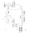
- FIG. 1 is a system configuration diagram of a vehicle including a braking control system according to the present invention.
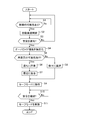
- 4 is a flowchart of automatic braking control according to the present invention.
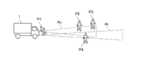
- FIG. 4 is a schematic diagram schematically illustrating an example of a state in which an object detection unit of a vehicle monitors surroundings.
- FIG. 3 is a schematic diagram schematically illustrating an example of a state in which a collision detection unit of a vehicle has detected a collision.
- FIG. 7 is a schematic diagram schematically illustrating an example of a state in which an object detection unit predicts a re-collision after a collision detection unit detects a collision.
- FIG. 9 is a schematic diagram schematically illustrating an example of a state in which a re-collision is not predicted in the object detection unit after the collision detection unit detects a collision.
- FIG. 1 is a system configuration diagram of a vehicle 1 including a braking control system according to the present invention.
- the vehicle 1 is configured as an engine truck, but may be an electric truck including an electric motor (motor) or a hybrid truck including both an internal combustion engine and an electric motor. Further, the vehicle 1 is not limited to a truck, and may be another type of vehicle such as a bus or a work vehicle.
- the vehicle 1 includes the traveling drive system 10, the traveling operation system 20, the peripheral device 30 for automatic braking, and the vehicle ECU 40 as a “control unit”.
- the vehicle 1 appropriately includes components (not shown) included in the conventional truck in addition to the above configuration.
- the traveling drive system 10 includes an engine 11, a clutch 12, a transmission 13, a propeller shaft 14, a differential device 15, a drive shaft 16, a drive wheel 17, a brake device 18, and an engine ECU 19.
- the clutch 12 is connected to the output shaft of the engine 11, and the input side of the transmission 13 is connected to the clutch 12.
- a differential device 15 is connected to an output side of the transmission 13 via a propeller shaft 14, and left and right drive wheels 17 are connected to the differential device 15 via a drive shaft 16. Then, the driving force generated by the engine 11 is transmitted to a pair of driving wheels 17 after being shifted by the transmission 13 to cause the vehicle 1 to travel.
- the brake device 18 generates a braking force for decelerating the vehicle 1 when the driver of the vehicle 1 performs a brake operation. Further, when automatic braking control, which will be described in detail later, is performed, the braking device 18 generates a braking force for decelerating the vehicle 1 based on control from the vehicle ECU 40 without the driver performing a braking operation. Let it.
- the engine ECU 19 receives an accelerator operation by the driver of the vehicle 1 and a torque command value from the vehicle ECU 40, generates a driving force for the engine 11 with respect to the positive torque command value, and changes the torque to a negative torque command value. On the other hand, an engine brake is generated.
- the traveling operation system 20 includes an accelerator pedal 21, an accelerator sensor 22, a brake pedal 23, and a brake switch 24.
- the accelerator sensor 22 detects the operation amount of the accelerator pedal 21 and transmits the detected operation amount to the vehicle ECU 40 described later.
- the vehicle ECU 40 calculates a required torque based on the accelerator operation amount and the like, and controls the engine 11 via the engine ECU 19, thereby controlling the vehicle 1 at an acceleration corresponding to the driver's depression operation on the accelerator pedal 21. Accelerate.
- the brake switch 24 detects the operation amount of the brake pedal 23 and transmits the detected operation amount to the vehicle ECU 40.
- the vehicle ECU 40 controls the brake device 18 based on the brake operation amount and the like, thereby decelerating the vehicle 1 at a negative acceleration corresponding to the driver's depression operation on the brake pedal 23.
- the automatic braking peripheral device 30 includes an object detection unit 31, a collision detection unit 32, a warning output unit 33, and a communication unit 34.
- the object detection unit 31 is a sensor that detects an object around the vehicle 1, and is, for example, a so-called fusion sensor including a camera and a radar in the present embodiment.
- the object detection unit 31 is used to monitor obstacles around the vehicle 1 such as pedestrians, other vehicles, guardrails, and buildings, and particularly to detect an object that may collide in front of the vehicle 1. You.
- the object detection unit 31 may appropriately include a sensor that monitors the rear of the vehicle 1, and may detect a following vehicle that may be hit by a collision.
- the collision detection unit 32 is a sensor that detects a collision between the vehicle 1 and another object, and is installed on a front bumper of the vehicle 1.
- the collision detection unit 32 can be configured by, for example, stretching a rubber tube provided with a pressure sensor around a front bumper, and measuring the internal pressure of the rubber tube deformed by the pressure received by contact with the object to thereby collide with the object. Can be detected.
- the sensor for detecting the collision of the vehicle 1 is not limited to the mode illustrated here, and various changes can be made.
- the warning output unit 33 is a device for notifying the vicinity of the vehicle 1 of danger by emitting a sound or light in an emergency.
- the warning output unit 33 may be, for example, a headlight or a horn mounted on a conventional automobile. In this case, the headlight is continuously blinked or the horn is continuously sounded. It urges pedestrians and other vehicles around the vehicle 1 to perform an evacuation action.
- the communication unit 34 is a wireless communication terminal for establishing two-way communication and communication with a data center that manages the vehicle 1 like so-called telematics. Further, the communication unit 34 may communicate with the outside of the vehicle via a roadside communication system or the like that is appropriately installed on the roadside.
- FIG. 2 is a flowchart of the automatic braking control according to the present invention. More specifically, FIG. 2 shows the automatic braking control of the vehicle 1 executed mainly by the vehicle ECU 40, and is a control procedure executed in parallel with the driving operation by the driver during the operation of the vehicle 1.
- the vehicle ECU 40 monitors the periphery of the vehicle 1 with a camera and a radar serving as the object detection unit 31, and determines a collision between the detected object and the vehicle based on the relative arrangement of the detected object and the vehicle speed and the like. It is determined whether there is a feared object (step S1).
- FIG. 3 is a schematic diagram schematically illustrating an example of a state where the object detection unit 31 of the vehicle 1 monitors the surroundings.
- the vehicle 1 detects the first pedestrian P1 as a surrounding object in the detection area Ac of the camera and the detection area Ar of the radar by the object detection unit 31.
- the surrounding objects are not limited to pedestrians, but refer to any obstacles that can collide with the vehicle 1.
- Vehicle ECU 40 continues to monitor the surroundings as long as no object that may cause a collision is detected (No in step S1). That is, the vehicle ECU 40 continues to give priority to the driving operation of the driver when the surrounding object is not detected, or when the possibility of collision is low even if it is detected.
- step S2 when it is predicted that there is a possibility of collision in monitoring the vicinity of the vehicle 1 (Yes in step S1), the vehicle ECU 40 performs automatic deceleration control to reduce the collision risk (step S2). That is, even when the operation of the brake pedal 23 by the driver is not detected, the vehicle ECU 40 causes the brake device 18 to generate a braking force and automatically decelerate the vehicle 1 by executing the automatic deceleration control.
- the vehicle ECU 40 determines whether or not the collision detection unit 32 detects a collision between the vehicle 1 and an object (Step S3).
- the vehicle ECU 40 permits the vehicle 1 to continue running by returning to the state of step S1.
- the vehicle ECU 40 is in a state where the automatic brake based on the automatic deceleration control has been activated in step S2.
- the override is performed.
- the predetermined operation may include, in addition, switch-off of the automatic deceleration control itself by the driver, operation of a steering wheel for collision avoidance, operation of a direction indicator, and the like.
- Step S4 when the automatic braking based on the automatic deceleration control is activated, or the automatic braking based on the automatic deceleration control is released by the override control, and the collision detection unit 32 detects the collision of the vehicle 1. (Yes in Step S3), the vehicle ECU 40 disables the override control to prohibit the release of the automatic brake based on the automatic deceleration control (Step S4).
- FIG. 4 is a schematic diagram schematically illustrating an example of a state in which the collision detection unit 32 of the vehicle 1 has detected a collision.
- the vehicle ECU 40 assumes that the collision detection unit 32 provided in the front bumper of the vehicle 1 has detected contact with the first pedestrian P1. However, the collision detection unit 32 does not have to identify whether or not the collision target is a person.
- step S5 if a re-collision of the vehicle 1 is predicted (Yes in step S5), the vehicle ECU 40 automatically avoids the collision by, for example, immediately stopping the vehicle 1 to avoid the re-collision. Control for generating power is performed (step S6).
- FIG. 5 is a schematic diagram schematically illustrating an example of a state in which the object detection unit 31 predicts a re-collision after the collision detection unit 32 detects a collision. More specifically, in the state of FIG. 5, the collision detection unit 32 detects that the vehicle 1 has collided with the first pedestrian P1, and at this time, the second pedestrian P2 in front of the vehicle 1 The object detection unit 31 detects the fourth to fourth pedestrians P4 as objects for which re-collision is predicted.
- the vehicle ECU 40 In such a state, the vehicle ECU 40 generates a relatively strong braking force on the brake device 18 and stops the vehicle 1 as soon as possible to avoid collision with an object. In addition, the vehicle ECU 40 issues a warning around the vehicle 1 via the warning output unit 33, and urges the pedestrian and other vehicles to perform an evacuation action (step S7). Thereby, the vehicle 1 can reduce the possibility of causing a collision accident again after colliding with the object. Steps S6 and S7 may be performed at the same time, or one of them may be performed first.
- step S5 when it is expected that the possibility of re-collision of the vehicle 1 is low (No in step S5), the vehicle ECU 40 generates a relatively weak braking force on the brake device 18 and automatically controls the vehicle 1 The speed is gradually reduced (step S8). The vehicle 1 will eventually stop unless the accelerator operation by the driver is continued.
- FIG. 6 is a schematic diagram schematically illustrating an example of a state in which a re-collision is not predicted in the object detection unit 31 after the collision detection unit 32 detects a collision. More specifically, in the state of FIG. 6, the collision detection unit 32 detects that the vehicle 1 has collided with the first pedestrian P ⁇ b> 1. No object is detected.
- the vehicle ECU 40 can cause the vehicle 1 to slow down while suppressing rapid deceleration by generating a relatively weak braking force on the brake device 18, and can also stop the vehicle.
- the vehicle 1 can move to a place where there is no risk of being hit by a following vehicle, and can reduce the impact force on a driver or another occupant due to so-called sudden braking.
- the vehicle ECU 40 shifts to a safe mode in which the maximum speed of the vehicle 1 is limited (step S9).
- the safe mode permits the vehicle 1 to move slowly after a collision, and in the present embodiment, the vehicle speed is suppressed to, for example, 5 km / h or less. Thereby, the vehicle 1 can reduce the possibility that a new collision accident will occur after the collision with the object. Further, even if the vehicle 1 is stopped in a dangerous state by the automatic brake operated in step S6 or step S8, emergency evacuation to a safe place at low speed can be performed. Further, there is also an effect of suppressing escape of a malicious driver.
- the vehicle 1 may be gradually decelerated in step S8 and then stopped, and then may be shifted to the safe mode in step S9.
- the process may directly shift to the safe mode in step S9.
- the mode may be shifted to the safe mode with the detection of the collision of the vehicle 1 as a trigger.
- the vehicle ECU 40 communicates with or communicates with the data center that manages the vehicle 1 via the communication unit 34, and confirms safety by, for example, collecting data on the accident situation of the vehicle 1 by an operator of the data center. (Step S10). Then, the operator sends the vehicle 1 from the data center to the vehicle 1 on the condition that the safety is confirmed, for example, when the collision of the vehicle 1 is an objective accident and is minor, or when the collision detection itself is erroneously recognized. A safe mode release signal is transmitted to the communication unit 34 (Yes in step S10). In addition, while communication unit 34 does not receive the release signal, vehicle ECU 40 suspends release of the safe mode (No in step S10).
- step S9 the vehicle ECU 40 releases the safe mode executed in step S9 (step S11), and ends a series of automatic braking control procedures.
- the release of the safe mode does not necessarily have to be performed by communication via the communication unit 34, and may be automatically performed, for example, a predetermined time after the shift to the safe mode.
- the vehicle ECU 40 may be configured to include, for example, a timer (not shown) so as to be automatically released, for example, 10 minutes after the shift to the safe mode.
- the braking control system monitors the surrounding objects by the object detection unit 31 when the collision detection unit 32 detects the collision of the vehicle 1, thereby further increasing the possibility of a collision. Predict. Then, the braking control system performs control to stop the vehicle 1 immediately when there is a possibility of re-collision, and performs control to gradually decelerate the vehicle 1 when there is no possibility of re-collision. As a result, the braking control system according to the present invention reduces the risk of a second collision occurring after the occurrence of a collision accident, and reduces the impact on the driver and other occupants when the second collision can be avoided. It is possible to safely slow down or stop the vehicle 1 and to suppress the spread of damage after a collision accident occurs.
- the present invention is not limited to the above embodiment.
- the mode is described in which the automatic deceleration control is performed based on the detection information of the object detection unit 31 even before the collision detection unit 32 detects a collision.
- automatic braking control after a collision may be performed. That is, in this case, the braking control system executes the automatic braking control from step S3 in the flowchart of FIG.
- the braking control system according to the present invention performs the automatic braking control after step S3 in the flowchart of FIG. 2 even if the prediction of the collision fails after performing the collision prediction before the collision. be able to.
Landscapes
- Engineering & Computer Science (AREA)
- Mechanical Engineering (AREA)
- Transportation (AREA)
- Regulating Braking Force (AREA)
Abstract
【課題】衝突事故が発生した後に更なる被害の拡大を抑制する制動制御システムを提供すること。 【解決手段】制動制御システムは、車両1の周辺の物体を検知する物体検知部31と、車両1の衝突を検知する衝突検知部32と、物体検知部31及び衝突検知部32の検知情報に基づいて、車両1の制動力を制御する車両ECU40と、を備え、車両ECU40は、衝突検知部32が衝突を検知した後に、更なる衝突が予測される場合には車両1に自動で衝突を回避させる制動力を発生させる制御を行い、衝突が予測されない場合には車両1を自動で徐々に減速させる制動力を発生させる制御を行う。
Description
本発明は、車両のブレーキを制御する制動制御システムに関する。
現在車両に搭載されている衝突被害軽減ブレーキ等の安全装置は、センサやカメラによって検出された物体に反応して自動ブレーキが作動するように構成されている。このような安全装置は、所定の条件を満たせば作動するが、誤作動を抑止する観点から適用される条件には制限が設けられ、また、自動ブレーキが作動してもドライバによるアクセル操作等があれば当該自動ブレーキを解除するオーバライド制御が行われることにより、ドライバ操作を優先するよう構成されている場合がある。
上記のような衝突被害軽減ブレーキ等の安全装置は、自動ブレーキの作動中においてドライバが誤ってアクセルを踏んでしまったときには、ドライバの意図に反して自動ブレーキの作動がオーバライドされてしまうことがある。この場合、車両は、たとえ人や物体との衝突が起こった後でさえも走行が継続されることになり、路上の負傷者を巻き込む可能性や、悪意のあるドライバに逃走を許してしまう可能性がある。このような問題への対策として、例えば特許文献1に開示された従来技術では、車両が物体に衝突したことを検知した場合には自動的に外部機関に通報すると共に、当該通報が完了するまではブレーキの作動状態を保持するよう構成されている。
しかしながら、上記のような従来技術では、車両が物体に衝突した場合には無条件で車両を停止させるため、衝突後に路上に留まることにより後続車による新たな追突事故が発生する虞が生じる。
本発明は、このような状況に鑑みてなされたものであり、その目的とするところは、衝突事故が発生した後に更なる被害の拡大を抑制する制動制御システムを提供することにある。
<本発明の第1の態様>
本発明の第1の態様は、車両の周辺の物体を検知する物体検知部と、前記車両の衝突を検知する衝突検知部と、前記物体検知部及び前記衝突検知部の検知情報に基づいて、前記車両の制動力を制御する制御部と、を備え、前記制御部は、前記衝突検知部が衝突を検知した後に、前記物体検知部からの情報により、更なる衝突が予測される場合には前記車両に自動で衝突を回避させる制動力を発生させる制御を行い、衝突が予測されない場合には前記車両を自動で徐々に減速させる制動力を発生させる制御を行う、制動制御システムである。
本発明の第1の態様は、車両の周辺の物体を検知する物体検知部と、前記車両の衝突を検知する衝突検知部と、前記物体検知部及び前記衝突検知部の検知情報に基づいて、前記車両の制動力を制御する制御部と、を備え、前記制御部は、前記衝突検知部が衝突を検知した後に、前記物体検知部からの情報により、更なる衝突が予測される場合には前記車両に自動で衝突を回避させる制動力を発生させる制御を行い、衝突が予測されない場合には前記車両を自動で徐々に減速させる制動力を発生させる制御を行う、制動制御システムである。
制動制御システムは、衝突検知部において車両の衝突が検知された場合に、物体検知部により周辺の物体を監視することで、更なる衝突の可能性を予測する。そして、制動制御システムは、再衝突の可能性がある場合には、例えば直ちに車両を停車させるなど、自動で衝突を回避させる制動力を発生させる制御を行い、再衝突の可能性がない場合には徐々に車両を減速させる制御を行う。これにより、本発明に係る制動制御システムは、衝突事故の発生後において再度の衝突が発生する虞を低減しつつ、再衝突を回避できる場合にはドライバ及び他の乗員に対する衝撃を緩和しながら車両を安全に減速させることができ、衝突事故が発生した後の二次被害を抑制することができる。
<本発明の第2の態様>
本発明の第2の態様は、上記した本発明の第1の態様において、前記制御部は、前記車両に自動で制動力を発生させる制御を行うと共に、前記車両の最大速度を制限するセーフモードに移行する、前記車両の最大速度を制限するセーフモードに移行する、制動制御システムである。
本発明の第2の態様は、上記した本発明の第1の態様において、前記制御部は、前記車両に自動で制動力を発生させる制御を行うと共に、前記車両の最大速度を制限するセーフモードに移行する、前記車両の最大速度を制限するセーフモードに移行する、制動制御システムである。
制動制御システムは、車両の衝突を検知して当該車両を減速させると共に、車両の走行速度に上限を設けることによって、再び衝突事故を起こす可能性があるような速度にまで加速できないように車速を制限する。また、制動制御システムは、衝突事故の発生後の制御により、万が一危険な場所で停車した場合であっても、少なくとも徐行による移動を許可することにより、安全な場所への緊急避難を行うことができる。これにより、制動制御システムは、衝突事故の発生後における再衝突を抑制しつつ、例えば後続車による追突などの二次被害の可能性をも低減することができる。
<本発明の第3の態様>
本発明の第3の態様は、上記した本発明の第2の態様において、前記制御部は、前記セーフモードに移行してから所定時間後に前記セーフモードを解除する、制動制御システムである。
本発明の第3の態様は、上記した本発明の第2の態様において、前記制御部は、前記セーフモードに移行してから所定時間後に前記セーフモードを解除する、制動制御システムである。
制動制御システムは、衝突事故の発生後において、車両の最大速度が制限されるセーフモードに移行することで二次被害の可能性を低減し、安全を確保するための時間が経過した後に当該セーフモードを自動的に解除する。これにより、制動制御システムは、衝突事故の発生後における事故処理が完了した後に、セーフモードを解除するための操作を不要とすることができる。
<本発明の第4の態様>
本発明の第4の態様は、上記した本発明の第2の態様において、前記制御部は、車両外部との通信により前記車両の安全を確認した場合に、前記セーフモードを解除する、制動制御システムである。
本発明の第4の態様は、上記した本発明の第2の態様において、前記制御部は、車両外部との通信により前記車両の安全を確認した場合に、前記セーフモードを解除する、制動制御システムである。
制動制御システムは、衝突事故の発生後において、車両の最大速度が制限されるセーフモードに移行することで二次被害の可能性を低減し、例えば車両を管理するデータセンタにより当該車両の安全が確認されたことを条件として、セーフモードの解除を許可してもらう構成としてもよい。これにより、制動制御システムは、車両のドライバの判断だけではセーフモードの解除を許可しないため、例えば、悪意のあるドライバが衝突後に逃走を図ろうとした場合であっても、逃走を阻止することができる。また、データセンタは、管理対象の車両の事故発生を把握することができる。
<本発明の第5の態様>
本発明の第5の態様は、上記した本発明の第1乃至4のいずれかの態様において、前記制御部は、前記車両に自動で衝突を回避させる制動力を発生させる制御を行う場合に、前記車両の周辺に警告を発する制御を行う、制動制御システムである。
本発明の第5の態様は、上記した本発明の第1乃至4のいずれかの態様において、前記制御部は、前記車両に自動で衝突を回避させる制動力を発生させる制御を行う場合に、前記車両の周辺に警告を発する制御を行う、制動制御システムである。
制動制御システムは、衝突事故の発生後において、再衝突の可能性がある場合には、衝突を回避するための制御を行いながら周辺に警告を発することで、周辺の歩行者及び他車両に対して退避行動を促し、再衝突の可能性をさらに低減することができる。
<本発明の第6の態様>
本発明の第6の態様は、上記した本発明の第1乃至5のいずれかの態様において、前記制御部は、衝突が予測される場合に前記車両を自動的に減速させる自動減速制御を行うと共に、前記車両にドライバによる所定の操作が行われた場合には前記自動減速制御を解除するオーバライド制御を行い、前記衝突検知部が衝突を検知した後においては前記オーバライド制御を無効化する、制動制御システムである。
本発明の第6の態様は、上記した本発明の第1乃至5のいずれかの態様において、前記制御部は、衝突が予測される場合に前記車両を自動的に減速させる自動減速制御を行うと共に、前記車両にドライバによる所定の操作が行われた場合には前記自動減速制御を解除するオーバライド制御を行い、前記衝突検知部が衝突を検知した後においては前記オーバライド制御を無効化する、制動制御システムである。
制動制御システムは、車両に衝突の可能性があると予測される場合には当該車両を自動的に減速させる自動減速制御を行うと共に、自動減速制御の作動中にドライバによるアクセル操作等の所定の操作が行われた場合にはオーバライド制御により自動減速制御を解除する。これにより、制動制御システムは、ドライバのブレーキ操作が検出されない場合であっても、車両に衝突の可能性がある場合には自動的に車両を減速させて衝突を回避し、また、誤作動等による自動減速制御をキャンセルすることができるように、自動減速制御の作動中における所定の操作によってドライバの運転操作を優先する。一方、衝突事故の発生後においては、制動制御システムは、オーバライド制御を無効にすることにより、自動減速制御中においてドライバが所定の操作をした場合、例えば誤ってアクセルを踏んでしまった場合であっても、自動減速制御が解除されてしまうことを防止することができる。
以下、図面を参照し、本発明の実施の形態について詳細に説明する。なお、本発明は以下に説明する内容に限定されるものではなく、その要旨を変更しない範囲において任意に変更して実施することが可能である。また、実施の形態の説明に用いる図面は、いずれも構成部材を模式的に示すものであって、理解を深めるべく部分的な強調、拡大、縮小、または省略などを行っており、構成部材の縮尺や形状等を正確に表すものとはなっていない場合がある。
図1は、本発明に係る制動制御システムを備える車両1のシステム構成図である。本実施形態において、車両1は、エンジントラックとして構成されているが、電動機(モータ)を備える電動トラックや、内燃機関及び電動機を両方備えるハイブリッドトラックであってもよい。また、車両1はトラックに限定されることなく、バスや作業車両などの他の種類の車両であってもよい。
車両1は、走行駆動システム10、走行操作システム20、自動制動用周辺機器30、及び「制御部」としての車両ECU40を備える。尚、車両1は、当該構成以外にも、従来のトラックが備える図示しないコンポーネントを適宜備えている。
走行駆動システム10は、エンジン11、クラッチ12、変速機13、プロペラシャフト14、差動装置15、駆動軸16、駆動輪17、ブレーキ装置18、及びエンジンECU19を備える。
エンジン11の出力軸にはクラッチ12が連結され、クラッチ12には変速機13の入力側が連結されている。変速機13の出力側にはプロペラシャフト14を介して差動装置15が連結され、差動装置15には駆動軸16を介して左右の駆動輪17が連結されている。そして、エンジン11が発生させた駆動力は、変速機13で変速された後に一対の駆動輪17に伝達されて車両1を走行させる。
ブレーキ装置18は、車両1のドライバがブレーキ操作を行うことにより、車両1を減速させるための制動力を発生させる。また、ブレーキ装置18は、詳細を後述する自動制動制御が行われる場合には、ドライバがブレーキ操作を行わなくても車両ECU40からの制御に基づいて、車両1を減速させるための制動力を発生させる。
エンジンECU19は、車両1のドライバによるアクセル操作や車両ECU40からトルク指令値が入力されると共に、正側のトルク指令値に対してはエンジン11に駆動力を発生させ、負側のトルク指令値に対してはエンジンブレーキを発生させる。
走行操作システム20は、アクセルペダル21、アクセルセンサ22、ブレーキペダル23、及びブレーキスイッチ24を備える。
車両1のドライバがアクセルペダル21を踏込み操作すると、アクセルセンサ22は、アクセルペダル21の操作量を検出し、後述する車両ECU40へ伝達する。これにより、車両ECU40は、アクセル操作量等に基づいて必要な要求トルクを算出し、エンジンECU19を介してエンジン11を制御することにより、ドライバのアクセルペダル21に対する踏込み操作に応じた加速度で車両1を加速させる。
車両1のドライバがブレーキペダル23を踏込み操作すると、ブレーキスイッチ24は、ブレーキペダル23の操作量を検出し、車両ECU40へ伝達する。これにより、車両ECU40は、ブレーキ操作量等に基づいてブレーキ装置18を制御することにより、ドライバのブレーキペダル23に対する踏込み操作に応じた負の加速度で車両1を減速させる。
自動制動用周辺機器30は、物体検知部31、衝突検知部32、警告出力部33、通信部34を含む。
物体検知部31は、車両1の周辺の物体を検知するセンサであり、例えば本実施形態においてはカメラ及びレーダーからなる所謂フュージョンセンサである。物体検知部31は、歩行者、他の車両、ガードレール、及び建物等、車両1の周辺の障害物を監視し、特に車両1の前方において衝突の可能性がある物体を検知するために使用される。また、物体検知部31は、車両1の後方を監視するセンサを適宜含むことができ、追突される可能性がある後続車を検知してもよい。
衝突検知部32は、車両1と他の物体との衝突を検知するセンサであり、車両1のフロントバンパーに設置される。衝突検知部32は、例えば圧力センサを備えたゴムチューブをフロントバンパーに張り巡らせて構成することができ、物体との接触により受ける圧力で変形したゴムチューブの内圧を測定することにより、物体との衝突を検知することができる。尚、車両1の衝突を検知するセンサは、ここで例示した態様に限られるものではなく、種々の変更が可能である。
警告出力部33は、緊急時に音や光を発することで、車両1の周辺に危険を知らせるための装置である。警告出力部33は、例えば従来の自動車に搭載されるヘッドライトやクラクションであってもよく、この場合にはヘッドライトを連続的に点滅させたり、クラクションを連続的に鳴動させたりすることで、車両1の周辺の歩行者及び他車両に対して退避行動を促す。
通信部34は、所謂テレマティクスのように、車両1を管理するデータセンタとの間で双方向の通信及び通話を確立するための無線通信端末である。また、通信部34は、路側に適宜設置されている路側通信システムなどを介して車両外部との通信を行なってもよい。
車両ECU40は、車両1の全体を統合制御するための制御装置である。車両ECU40は、物体検知部31及び衝突検知部32の検知情報や、上記した各種センサからの情報以外にも、例えば車両1の速度やエンジン11の回転数などを取得する。そして、物体検知部31、衝突検知部32、及び車両ECU40により構成される「制動制御システム」によって、車両1の衝突を抑制する自動制動制御が行われる。以下、自動制動制御の流れについて説明する。
図2は、本発明に係る自動制動制御のフローチャートである。より詳しくは、図2は、車両ECU40を中心として実行される車両1の自動制動制御を示しており、車両1の運行中においてドライバによる運転操作と並行して実行される制御手順である。
自動制動制御がスタートすると、車両ECU40は、物体検知部31としてのカメラ及びレーダーにより車両1の周辺を監視し、検出される物体と自車との相対配置や車速との関係等から、衝突の虞がある物体があるか否かを判定する(ステップS1)。
図3は、車両1の物体検知部31が周辺を監視する状態の一例を模式的に表す模式図である。図3においては、車両1は、物体検知部31によるカメラの検知エリアAc及びレーダーの検知エリアArにおいて、周辺の物体としての第1歩行者P1を検出している。ここで、周辺の物体は、歩行者に限られるものではなく、車両1と衝突し得るあらゆる障害物を指す。
車両ECU40は、衝突の虞がある物体が検出されない間は、周辺の監視を継続する(ステップS1でNo)。すなわち、車両ECU40は、周辺の物体が検出されない場合、及び検出されても衝突の可能性が低い場合には、引き続きドライバの運転操作を優先した制御を行う。
一方、車両ECU40は、車両1の周辺の監視において衝突の可能性があると予測された場合には(ステップS1でYes)、衝突リスクを低減させるべく、自動減速制御を行う(ステップS2)。つまり、車両ECU40は、ドライバによるブレーキペダル23の操作が検出されない場合であっても、自動減速制御を実行することにより、ブレーキ装置18に制動力を発生させて自動的に車両1を減速させる。
衝突リスクを低減させる自動減速制御が実行されると、車両ECU40は、衝突検知部32により車両1と物体との衝突が検知されたか否かを判定する(ステップS3)。
衝突検知部32が車両1の衝突を検知しなかった場合には(ステップS3でNo)、車両ECU40は、ステップS1の状態に戻ることにより、車両1の走行継続を許可する。ここで、車両ECU40は、ステップS2において自動減速制御に基づく自動ブレーキが作動した状態となっているが、ドライバによるオーバライド条件を満たす所定の操作、例えばアクセルペダル21が操作された場合には、オーバライド制御により当該自動ブレーキを解除することで通常の走行モードに復帰する。なお、所定の操作には、その他にも、ドライバによる自動減速制御自体のスイッチオフ、衝突回避のためのハンドル操作、方向指示器の操作等が含まれ得る。
これに対し、自動減速制御に基づく自動ブレーキが作動したにも拘らず、あるいは自動減速制御に基づく自動ブレーキがオーバライド制御により解除されてしまい、衝突検知部32において車両1の衝突が検知された場合には(ステップS3でYes)、車両ECU40は、オーバライド制御を無効化することにより自動減速制御に基づく自動ブレーキの解除を禁止する(ステップS4)。
図4は、車両1の衝突検知部32が衝突を検知した状態の一例を模式的に表す模式図である。ここでは、車両ECU40は、車両1のフロントバンパーに設けられた衝突検知部32が第1歩行者P1との接触を検知したものとしている。ただし、衝突検知部32は、衝突した対象が人か否かを識別していなくてもかまわない。
そして、車両ECU40は、車両1の衝突が検知された場合に、再衝突の可能性を判定する(ステップS5)。すなわち、車両ECU40は、物体検知部31からの情報によって車両1の周辺の状況を確認し、再び衝突する虞のある物体があるか否かを判定する。
ここで、車両ECU40は、車両1の再衝突が予測される場合には(ステップS5でYes)、再衝突を回避するために、例えば車両1を直ちに停車させるなど、自動で衝突を回避させる制動力を発生させる制御を行う(ステップS6)。
図5は、衝突検知部32が衝突を検知した後に、物体検知部31が再衝突を予測した状態の一例を模式的に表す模式図である。より具体的には、図5の状態においては、車両1が第1歩行者P1に衝突したことを衝突検知部32が検知しており、また、このとき車両1の前方における第2歩行者P2~第4歩行者P4を、再衝突が予測される物体として物体検知部31が検知している。
このような状態においては、車両ECU40は、ブレーキ装置18に対して比較的強い制動力を発生させ、物体との衝突を回避すべく可能な限り速やかに車両1を停車させる。また、車両ECU40は、警告出力部33を介して車両1の周辺に警告を発し、歩行者及び他車両に対して退避行動を促す(ステップS7)。これにより車両1は、物体に衝突した後に、再び衝突事故を引き起こす虞を低減することができる。なお、ステップS6とステップS7は同時に行われてもよいし、いずれかが先に行われてもかまわない。
一方、車両1の再衝突の可能性が低いと予想される場合には(ステップS5でNo)、車両ECU40は、ブレーキ装置18に対して比較的弱い制動力を発生させ、車両1を自動で徐々に減速させる(ステップS8)。尚、車両1は、ドライバによるアクセル操作が継続されていない限り、やがては停車することになる。
図6は、衝突検知部32が衝突を検知した後に、物体検知部31において再衝突が予測されない状態の一例を模式的に表す模式図である。より具体的には、図6の状態においては、車両1が第1歩行者P1に衝突したことを衝突検知部32が検知しているが、このとき車両1の周辺に再衝突の虞がある物体が検知されていない。
このような状態においては、車両ECU40は、ブレーキ装置18に対して比較的弱い制動力を発生させることで、急激な減速を抑制しながら車両1を徐行させることができ、停車させることもできる。これにより車両1は、物体に衝突した後に、後続車に追突される虞のない場所に移動することができると共に、いわゆる急ブレーキによるドライバ又は他の乗員への衝撃力を緩和することができる。
そして、車両ECU40は、車両1を自動で減速させる制御を行なった後、車両1の最大速度を制限するセーフモードに移行する(ステップS9)。セーフモードは、衝突後の車両1の徐行による移動を許可するものであり、本実施形態においては車速を例えば5km/h以下に抑制する。これにより、車両1は、物体との衝突後に新たな衝突事故が発生する虞を低減することができる。また、車両1は、ステップS6又はステップS8で作動する自動ブレーキにより万が一危険な状態で停車してしまった場合であっても、低速で安全な場所への緊急避難を行うことができる。さらに、悪意のあるドライバの逃走を抑制する効果もある。尚、セーフモードへの移行の態様については、ステップS8において車両1を徐々に減速させて、停止させた後にステップS9のセーフモードに移行させてもよいし、車両1を徐々に減速させて、セーフモードで制限された最大速度になったらそのままステップS9のセーフモードに移行させてもよい。また、車両1の衝突を検知したことをトリガに、セーフモードに移行させてもよい。
また、車両ECU40は、通信部34を介して車両1を管理するデータセンタとの間で通信又は通話を行い、例えばデータセンタのオペレータが車両1の事故状況の情報収集を行うことで安全を確認する(ステップS10)。そして、オペレータは、例えば、車両1の衝突が対物事故で且つ軽微である場合や、衝突検知自体が誤認識であった場合などにより安全が確認されたことを条件として、データセンタから車両1の通信部34へセーフモードの解除信号を送信する(ステップS10でYes)。また、通信部34が当該解除信号を受信しない間は、車両ECU40は、セーフモードの解除を保留する(ステップS10でNo)。
通信部34がデータセンタからセーフモードの解除信号を受信すると、車両ECU40は、ステップS9で実行したセーフモードを解除し(ステップS11)、一連の自動制動制御の手順を終了する。
ここで、セーフモードの解除は、必ずしも通信部34を介した通信により行う必要はなく、例えばセーフモードへの移行時から所定時間後に自動で行われてもよい。より具体的には、車両ECU40は、例えば図示しないタイマを含むことにより、セーフモードへの移行時から例えば10分後に自動で解除されるように構成することもできる。
以上のように、本発明に係る制動制御システムは、衝突検知部32において車両1の衝突が検知された場合に、物体検知部31により周辺の物体を監視することで、更なる衝突の可能性を予測する。そして、制動制御システムは、再衝突の可能性がある場合には直ちに車両1を停車させる制御を行い、再衝突の可能性がない場合には徐々に車両1を減速させる制御を行う。これにより、本発明に係る制動制御システムは、衝突事故の発生後において再度の衝突が発生する虞を低減しつつ、再衝突を回避できる場合にはドライバ及び他の乗員に対する衝撃を緩和しながら車両1を安全に徐行や停車させることができ、衝突事故が発生した後の被害の拡大を抑制することができる。
以上で実施形態の説明を終えるが、本発明は上記した実施形態に限定されるものではない。例えば、上記の実施形態では、衝突検知部32が衝突を検知する前においても、物体検知部31の検知情報に基づいて自動減速制御を行う態様を例示したが、衝突前の衝突予測を行うことなく衝突後の自動制動制御を行なってもよい。すなわち、この場合には、制動制御システムは、図2のフローチャートのステップS3から自動制動制御を実行することになる。また、本発明に係る制動制御システムは、衝突前の衝突予測を行なった上で、万が一衝突の予測に失敗した場合であっても、図2のフローチャートのステップS3以降の自動制動制御を実行することができる。
1 車両
18 ブレーキ装置
21 アクセルペダル
23 ブレーキペダル
31 物体検知部
32 衝突検知部
40 車両ECU
18 ブレーキ装置
21 アクセルペダル
23 ブレーキペダル
31 物体検知部
32 衝突検知部
40 車両ECU
Claims (6)
- 車両の周辺の物体を検知する物体検知部と、
前記車両の衝突を検知する衝突検知部と、
前記物体検知部及び前記衝突検知部の検知情報に基づいて、前記車両の制動力を制御する制御部と、を備え、
前記制御部は、前記衝突検知部が衝突を検知した後に、前記物体検知部からの情報により、更なる衝突が予測される場合には前記車両に自動で衝突を回避させる制動力を発生させる制御を行い、衝突が予測されない場合には前記車両を自動で徐々に減速させる制動力を発生させる制御を行う、制動制御システム。 - 前記制御部は、前記車両に自動で制動力を発生させる制御を行うと共に、前記車両の最大速度を制限するセーフモードに移行する、請求項1に記載の制動制御システム。
- 前記制御部は、前記セーフモードに移行してから所定時間後に前記セーフモードを解除する、請求項2に記載の制動制御システム。
- 前記制御部は、車両外部との通信により前記車両の安全を確認した場合に、前記セーフモードを解除する、請求項2に記載の制動制御システム。
- 前記制御部は、前記車両に自動で衝突を回避させる制動力を発生させる制御を行う場合に、前記車両の周辺に警告を発する制御を行う、請求項1乃至4のいずれかに記載の制動制御システム。
- 前記制御部は、衝突が予測される場合に前記車両を自動的に減速させる自動減速制御を行うと共に、前記車両にドライバによる所定の操作が行われた場合には前記自動減速制御を解除するオーバライド制御を行い、前記衝突検知部が衝突を検知した後においては前記オーバライド制御を無効化する、請求項1乃至5のいずれかに記載の制動制御システム。
Applications Claiming Priority (2)
| Application Number | Priority Date | Filing Date | Title |
|---|---|---|---|
| JP2018143157A JP2020019319A (ja) | 2018-07-31 | 2018-07-31 | 制動制御システム |
| JP2018-143157 | 2018-07-31 |
Publications (1)
| Publication Number | Publication Date |
|---|---|
| WO2020026596A1 true WO2020026596A1 (ja) | 2020-02-06 |
Family
ID=69232447
Family Applications (1)
| Application Number | Title | Priority Date | Filing Date |
|---|---|---|---|
| PCT/JP2019/023007 Ceased WO2020026596A1 (ja) | 2018-07-31 | 2019-06-11 | 制動制御システム |
Country Status (2)
| Country | Link |
|---|---|
| JP (1) | JP2020019319A (ja) |
| WO (1) | WO2020026596A1 (ja) |
Cited By (1)
| Publication number | Priority date | Publication date | Assignee | Title |
|---|---|---|---|---|
| JP2022113370A (ja) * | 2021-01-25 | 2022-08-04 | 和博 山内 | 自動運転車 |
Families Citing this family (1)
| Publication number | Priority date | Publication date | Assignee | Title |
|---|---|---|---|---|
| JP7800189B2 (ja) * | 2022-02-17 | 2026-01-16 | スズキ株式会社 | 車両の運転支援装置 |
Citations (3)
| Publication number | Priority date | Publication date | Assignee | Title |
|---|---|---|---|---|
| JP2003081074A (ja) * | 2001-09-13 | 2003-03-19 | Hitachi Ltd | 自動車用ブレーキの制御方法及びその装置 |
| JP2005104320A (ja) * | 2003-09-30 | 2005-04-21 | Advics:Kk | 車両制御装置 |
| JP2016020106A (ja) * | 2014-07-11 | 2016-02-04 | トヨタ自動車株式会社 | 車両制御装置 |
-
2018
- 2018-07-31 JP JP2018143157A patent/JP2020019319A/ja active Pending
-
2019
- 2019-06-11 WO PCT/JP2019/023007 patent/WO2020026596A1/ja not_active Ceased
Patent Citations (3)
| Publication number | Priority date | Publication date | Assignee | Title |
|---|---|---|---|---|
| JP2003081074A (ja) * | 2001-09-13 | 2003-03-19 | Hitachi Ltd | 自動車用ブレーキの制御方法及びその装置 |
| JP2005104320A (ja) * | 2003-09-30 | 2005-04-21 | Advics:Kk | 車両制御装置 |
| JP2016020106A (ja) * | 2014-07-11 | 2016-02-04 | トヨタ自動車株式会社 | 車両制御装置 |
Cited By (1)
| Publication number | Priority date | Publication date | Assignee | Title |
|---|---|---|---|---|
| JP2022113370A (ja) * | 2021-01-25 | 2022-08-04 | 和博 山内 | 自動運転車 |
Also Published As
| Publication number | Publication date |
|---|---|
| JP2020019319A (ja) | 2020-02-06 |
Similar Documents
| Publication | Publication Date | Title |
|---|---|---|
| JP6032220B2 (ja) | 車両制御装置、及び、車両制御システム | |
| KR101775856B1 (ko) | 차량 제어 시스템 및 차량 제어 방법 | |
| JP6181678B2 (ja) | 車両制動制御装置 | |
| JP2019167115A5 (ja) | 自動運転制御装置及び車両 | |
| US11433862B2 (en) | Driver assistance system for a transportation vehicle, transportation vehicle, and method for operating a driver assistance system or transportation vehicle | |
| JP2010072969A (ja) | 周辺車両監視装置及び周辺車両監視方法 | |
| JP2008121583A (ja) | 車両制御装置 | |
| JP2014091380A (ja) | 運転走行支援装置 | |
| JP4084318B2 (ja) | 緊急ブレーキ装置 | |
| WO2018188860A1 (en) | A safety control system and method for use in vehicles | |
| CN116137848A (zh) | 用于处理涉及车辆和/或第三方的情况的方法以及系统 | |
| JP4454490B2 (ja) | 衝突防止支援方法及び衝突防止支援装置 | |
| WO2020026596A1 (ja) | 制動制御システム | |
| JP2016117319A (ja) | 運転支援装置 | |
| CN116394929B (zh) | 车辆碰撞的控制方法、控制装置及车辆 | |
| JP3918190B2 (ja) | 自動車において安全なタイヤ緊急走行操作を確実に行う方法 | |
| KR20130013997A (ko) | 차량의 충돌 방지장치 및 방법 | |
| KR20240007206A (ko) | 차량을 조작하는 방법 | |
| JP2014118048A (ja) | 運転支援装置 | |
| CN107776525A (zh) | 车辆防碰撞系统、车辆及其防碰撞方法 | |
| KR200489951Y1 (ko) | 자동차의 안전거리 유지 경고장치 | |
| US11958478B2 (en) | Method for automatically avoiding or mitigating collision, and control system, storage medium and motor vehicle | |
| JP6848478B2 (ja) | 二次衝突抑制装置 | |
| US20250074412A1 (en) | Vehicle traveling control apparatus | |
| KR20120005678A (ko) | 차량용 자동 주차 시스템 및 그 제어 방법 |
Legal Events
| Date | Code | Title | Description |
|---|---|---|---|
| 121 | Ep: the epo has been informed by wipo that ep was designated in this application |
Ref document number: 19845129 Country of ref document: EP Kind code of ref document: A1 |
|
| NENP | Non-entry into the national phase |
Ref country code: DE |
|
| 122 | Ep: pct application non-entry in european phase |
Ref document number: 19845129 Country of ref document: EP Kind code of ref document: A1 |