WO2020022185A1 - センサシステム - Google Patents
センサシステム Download PDFInfo
- Publication number
- WO2020022185A1 WO2020022185A1 PCT/JP2019/028292 JP2019028292W WO2020022185A1 WO 2020022185 A1 WO2020022185 A1 WO 2020022185A1 JP 2019028292 W JP2019028292 W JP 2019028292W WO 2020022185 A1 WO2020022185 A1 WO 2020022185A1
- Authority
- WO
- WIPO (PCT)
- Prior art keywords
- light
- data
- vehicle
- light receiving
- receiving element
- Prior art date
- Legal status (The legal status is an assumption and is not a legal conclusion. Google has not performed a legal analysis and makes no representation as to the accuracy of the status listed.)
- Ceased
Links
Images



Classifications
-
- G—PHYSICS
- G01—MEASURING; TESTING
- G01S—RADIO DIRECTION-FINDING; RADIO NAVIGATION; DETERMINING DISTANCE OR VELOCITY BY USE OF RADIO WAVES; LOCATING OR PRESENCE-DETECTING BY USE OF THE REFLECTION OR RERADIATION OF RADIO WAVES; ANALOGOUS ARRANGEMENTS USING OTHER WAVES
- G01S17/00—Systems using the reflection or reradiation of electromagnetic waves other than radio waves, e.g. lidar systems
- G01S17/88—Lidar systems specially adapted for specific applications
- G01S17/93—Lidar systems specially adapted for specific applications for anti-collision purposes
- G01S17/931—Lidar systems specially adapted for specific applications for anti-collision purposes of land vehicles
-
- G—PHYSICS
- G01—MEASURING; TESTING
- G01C—MEASURING DISTANCES, LEVELS OR BEARINGS; SURVEYING; NAVIGATION; GYROSCOPIC INSTRUMENTS; PHOTOGRAMMETRY OR VIDEOGRAMMETRY
- G01C19/00—Gyroscopes; Turn-sensitive devices using vibrating masses; Turn-sensitive devices without moving masses; Measuring angular rate using gyroscopic effects
-
- G—PHYSICS
- G01—MEASURING; TESTING
- G01P—MEASURING LINEAR OR ANGULAR SPEED, ACCELERATION, DECELERATION, OR SHOCK; INDICATING PRESENCE, ABSENCE, OR DIRECTION, OF MOVEMENT
- G01P15/00—Measuring acceleration; Measuring deceleration; Measuring shock, i.e. sudden change of acceleration
-
- G—PHYSICS
- G01—MEASURING; TESTING
- G01S—RADIO DIRECTION-FINDING; RADIO NAVIGATION; DETERMINING DISTANCE OR VELOCITY BY USE OF RADIO WAVES; LOCATING OR PRESENCE-DETECTING BY USE OF THE REFLECTION OR RERADIATION OF RADIO WAVES; ANALOGOUS ARRANGEMENTS USING OTHER WAVES
- G01S17/00—Systems using the reflection or reradiation of electromagnetic waves other than radio waves, e.g. lidar systems
- G01S17/02—Systems using the reflection of electromagnetic waves other than radio waves
- G01S17/06—Systems determining position data of a target
- G01S17/42—Simultaneous measurement of distance and other co-ordinates
-
- G—PHYSICS
- G01—MEASURING; TESTING
- G01S—RADIO DIRECTION-FINDING; RADIO NAVIGATION; DETERMINING DISTANCE OR VELOCITY BY USE OF RADIO WAVES; LOCATING OR PRESENCE-DETECTING BY USE OF THE REFLECTION OR RERADIATION OF RADIO WAVES; ANALOGOUS ARRANGEMENTS USING OTHER WAVES
- G01S7/00—Details of systems according to groups G01S13/00, G01S15/00, G01S17/00
- G01S7/48—Details of systems according to groups G01S13/00, G01S15/00, G01S17/00 of systems according to group G01S17/00
- G01S7/481—Constructional features, e.g. arrangements of optical elements
- G01S7/4814—Constructional features, e.g. arrangements of optical elements of transmitters alone
- G01S7/4815—Constructional features, e.g. arrangements of optical elements of transmitters alone using multiple transmitters
-
- G—PHYSICS
- G01—MEASURING; TESTING
- G01S—RADIO DIRECTION-FINDING; RADIO NAVIGATION; DETERMINING DISTANCE OR VELOCITY BY USE OF RADIO WAVES; LOCATING OR PRESENCE-DETECTING BY USE OF THE REFLECTION OR RERADIATION OF RADIO WAVES; ANALOGOUS ARRANGEMENTS USING OTHER WAVES
- G01S7/00—Details of systems according to groups G01S13/00, G01S15/00, G01S17/00
- G01S7/48—Details of systems according to groups G01S13/00, G01S15/00, G01S17/00 of systems according to group G01S17/00
- G01S7/481—Constructional features, e.g. arrangements of optical elements
- G01S7/4817—Constructional features, e.g. arrangements of optical elements relating to scanning
-
- G—PHYSICS
- G08—SIGNALLING
- G08G—TRAFFIC CONTROL SYSTEMS
- G08G1/00—Traffic control systems for road vehicles
- G08G1/16—Anti-collision systems
-
- G—PHYSICS
- G08—SIGNALLING
- G08G—TRAFFIC CONTROL SYSTEMS
- G08G1/00—Traffic control systems for road vehicles
- G08G1/16—Anti-collision systems
- G08G1/166—Anti-collision systems for active traffic, e.g. moving vehicles, pedestrians, bikes
Definitions
- the present disclosure relates to a sensor system mounted on a vehicle.
- a sensor for detecting information external to the vehicle In order to realize vehicle driving support technology, it is necessary to mount a sensor for detecting information external to the vehicle on the vehicle body.
- An example of such a sensor is a LiDAR (Light Detection and Ranging) sensor (for example, see Patent Document 1).
- a first aspect for responding to the above demand is a sensor system mounted on a vehicle, A first light emitting element that emits first detection light toward the outside of the vehicle, A second light emitting element that emits second detection light toward the outside of the vehicle, A first light receiving element that outputs a first signal according to the amount of incident light, A second light receiving element that outputs a second signal according to the amount of incident light, A processor that obtains first data corresponding to the first signal and second data corresponding to the second signal, With If the first data is based on the second detection light and the second data is based on the first detection light, the processor exchanges the first data with the second data.
- the sensor system can be configured as follows.
- a third light emitting element that is arranged between the first light emitting element and the second light emitting element and emits third detection light toward the outside of the vehicle
- a third light receiving element that is arranged between the first light receiving element and the second light receiving element and outputs a third signal according to the amount of incident light
- the processor obtains third data corresponding to the third signal, When both the first data and the third data are based on the first detection light or the third detection light, or both the second data and the third data are the second detection light or the When it is based on the third detection light, the processor generates average data by averaging the first data and the second data, and replaces the third data with the average data.
- the sensor system according to the first aspect can be configured as follows.
- the first light receiving element and the second light receiving element are arranged in a direction corresponding to a vertical direction of the vehicle.
- the vertical component of vehicle vibration is dominant. Therefore, the abnormal light reception described above is likely to occur between the first light receiving element and the second light receiving element arranged in the direction corresponding to the up-down direction of the vehicle.
- the processor can perform the above-described exchange and averaging of the first data and the second data, it is possible to effectively correct the influence of the reversal phenomenon of light reception caused by the vibration of the vehicle.
- the sensor system according to the first aspect can be configured as follows.
- the first light emitting element, the second light emitting element, the first light receiving element, and the second light receiving element are a part of at least one of a LiDAR sensor unit, a TOF camera unit, and a millimeter wave radar unit.
- a second aspect for responding to the above demand is a sensor system mounted on a vehicle, A sensor unit for detecting information outside the vehicle, A displacement sensor that detects a displacement of the sensor unit at least in a direction along a vertical direction of the vehicle; A processor that corrects data corresponding to the information based on the data corresponding to the displacement, It has.
- the influence of the displacement of the sensor unit due to the vibration of the vehicle on the information detection can be suppressed. Therefore, it is possible to suppress a decrease in the information acquisition capability of the sensor system due to vibration of the vehicle or the like.
- the sensor system according to the second aspect can be configured as follows.
- the sensor unit is at least one of a LiDAR sensor unit, a TOF camera unit, and a millimeter wave radar unit.
- sensor unit as used in this specification means a component unit of a component that has a desired information detection function and can be distributed as a single unit.
- driving assistance refers to a control process that at least partially performs at least one of a driving operation (steering operation, acceleration, deceleration), monitoring of a driving environment, and a backup of the driving operation.
- a driving operation steering operation, acceleration, deceleration
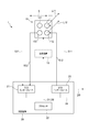
- FIG. 2 illustrates a functional configuration of the sensor system according to the first embodiment.
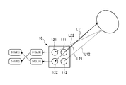
- FIG. 2 is a diagram for explaining an operation of the sensor system of FIG. 1.
- FIG. 2 is a diagram for explaining an operation of the sensor system of FIG. 1.
- 2 illustrates an operation flow of the sensor system of FIG. 2 shows another configuration example of the sensor system of FIG. 1.
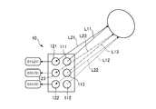
- FIG. 5 is a diagram for explaining an operation of the sensor system of FIG. 4.
- FIG. 5 is a diagram for explaining an operation of the sensor system of FIG. 4.
- 9 illustrates a functional configuration of a sensor system according to a second embodiment.
- FIG. 7 is a diagram for explaining an operation of the sensor system of FIG. 6.
- FIG. 7 is a diagram for explaining an operation of the sensor system of FIG. 6.
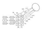
- FIG. 1 illustrates a functional configuration of the sensor system 1 according to the first embodiment.
- the sensor system 1 is mounted on a vehicle.
- the sensor system 1 includes the LiDAR sensor unit 10.
- the LiDAR sensor unit 10 includes a first light emitting element 111, a second light emitting element 112, a first light receiving element 121, and a second light receiving element 122.
- the first light emitting element 111 is configured to emit the first detection light L11 toward the outside of the vehicle.
- the first detection light L11 is invisible light.
- the invisible light for example, infrared light having a wavelength of 905 nm can be used.
- a semiconductor light emitting element such as a light emitting diode or a laser diode can be used.
- the second light emitting element 112 is configured to emit the second detection light L12 toward the outside of the vehicle.
- the second detection light L12 is invisible light.
- the invisible light for example, infrared light having a wavelength of 905 nm can be used.
- a semiconductor light emitting element such as a light emitting diode or a laser diode can be used.
- the first light receiving element 121 is configured to output a first light receiving signal S21 according to the amount of incident light.
- the first light receiving signal S21 is an example of a first signal.
- the first light receiving element 121 has sensitivity to at least the wavelength of the first detection light L11.
- a photodiode, a phototransistor, a photoresistor, or the like can be used as the first light receiving element 121.
- the second light receiving element 122 is configured to output the second light receiving signal S22 according to the amount of incident light.
- the second light receiving signal S22 is an example of a second signal.
- the second light receiving element 122 has sensitivity to at least the wavelength of the second detection light L12.
- a photodiode, a phototransistor, a photoresistor, or the like can be used as the second light receiving element 122.
- the sensor system 1 includes the control device 20.
- the control device 20 includes an input interface 21, a processor 22, an output interface 23, and a communication bus 24.
- the input interface 21, the processor 22, and the output interface 23 can exchange signals and data via a communication bus 24.
- the first light receiving signal S21 output from the first light receiving element 121 and the second light receiving signal S22 output from the second light receiving element 122 are input to the input interface 21.
- the processor 22 acquires the first data D1 and the second data D2 respectively corresponding to the first light receiving signal S21 and the second light receiving signal S22 input to the input interface 21.
- the first data D ⁇ b> 1 and the second data D ⁇ b> 2 are in a state where they can be used for information processing described later in the processor 22. That is, the input interface 21 has an appropriate circuit configuration for converting the first light receiving signal S21 and the second light receiving signal S22 into the first data D1 and the second data D2, respectively.
- the processor 22 controls the light emitting operation of the first light emitting element 111 by inputting the first control signal S11 to the first light emitting element 111 via the output interface 23. Specifically, the amount of the first detection light L11, light emission timing, light emission repetition frequency, and the like are controlled. By appropriately adjusting the light emission timing and performing the light modulation, identification information can be added to the first detection light L11.
- the processor 22 controls the light emitting operation of the second light emitting element 112 by inputting the second control signal S12 to the second light emitting element 112 via the output interface 23. Specifically, the light amount, light emission timing, light emission repetition frequency, and the like of the second detection light L12 are controlled. By appropriately adjusting the light emission timing and performing the light modulation, identification information can be added to the second detection light L12.
- the first detection light L11 emitted from the first light emitting element 111 is reflected by an object located outside the vehicle to generate first reflected light L21.
- the identification information given to the first detection light L11 is reflected on the first reflected light L21.
- the first reflected light L21 enters the first light receiving element 121.
- the first light receiving element 121 outputs a first light receiving signal S21 according to the amount of the first reflected light L21.
- first data D1 associated with the first reflected light L21 is obtained.
- the identification information given to the first detection light L11 is also reflected in the first data D1.
- the second detection light L12 emitted from the second light emitting element 112 is reflected by an object located outside the vehicle to generate a second reflected light L22.
- the identification information given to the second detection light L12 is reflected on the second reflected light L22.
- the second reflected light L22 enters the second light receiving element 122.
- the second light receiving element 122 outputs a second light receiving signal S22 corresponding to the amount of the second reflected light L22.
- the second data D2 associated with the second reflected light L22 is obtained.
- the identification information given to the second detection light L12 is also reflected on the second data D2.
- the processor 22 can obtain the distance to the object associated with the first reflected light L21 based on the time from when the first detection light L11 is emitted to when the first reflected light L21 is detected. In addition to or in place of this, information on attributes such as the material of the object associated with the first reflected light L21 can be acquired based on the difference between the waveforms of the first detected light L11 and the first reflected light L21.
- the processor 22 can acquire the distance to the object associated with the second reflected light L22 based on the time from when the second detection light L12 is emitted to when the second reflected light L22 is detected.
- information on attributes such as the material of the object associated with the second reflected light L22 can be acquired based on the difference between the waveforms of the second detection light L12 and the second reflected light L22.
- the LiDAR sensor unit 10 can include a scanning mechanism 13.
- the scanning mechanism 13 changes the emission direction of the first detection light L11 and the second detection light L12 along a direction S that intersects the arrangement direction of the first light emitting element 111 and the second light emitting element 112.
- the processor 22 can control the operation of the scanning mechanism 13 via the output interface 23.
- N N sets of first data D1 and second data D2 are obtained by repeating the light emitting operation and the light receiving operation N times during one scan. For example, by acquiring the distance information to the object described above for the N data sets, it is possible to acquire information on the shape of the object associated with the first reflected light L21 and the second reflected light L22.
- the processor 22 is configured to be able to output the data D0 including the information on the object located outside the vehicle acquired as described above to the outside via the output interface 23.
- the data D0 is used for further information processing by another processor.
- FIG. 3 illustrates the flow of processing performed by the processor 22.
- the processor 22 acquires the first data D1 and the second data D2 as described above (STEP 1).
- the processor 22 determines whether or not there is a light receiving inversion phenomenon (STEP 2). Specifically, it is determined whether the first data D1 is based on the first detection light L11. Similarly, it is determined whether the second data D2 is based on the second detection light L12.
- the first reflected light L21 generated by the first detection light L11 enters the first light receiving element 121, and the second reflection light generated by the second detection light L12.
- the light L22 is configured to enter the second light receiving element 122. Therefore, if the first data D1 is generated based on the first reflected light L21, the first data D1 reflects the identification information given to the first detection light L11. If the second data D2 is generated based on the second reflected light L22, the second data D2 reflects the identification information given to the first detection light L11.
- the processor 22 makes the above determination through detection of the identification information.
- the process returns to STEP1.
- the first reflected light L21 is incident on the second light receiving element 122
- the second reflected light L22 is incident on the first light receiving element.
- a situation in which the light enters the light source 121 may occur.
- the first data D1 generated based on the first light receiving signal S21 output from the first light receiving element 121 reflects the identification signal given to the second detection light L12.
- the second data D2 generated based on the second light receiving signal S22 output from the second light receiving element 122 the identification signal given to the first detection light L11 is reflected. If the first data D1 and the second data D2 are output as they are, the accuracy of the information on the object outside the vehicle obtained by the subsequent processing decreases.
- the processor 22 determines 2B, the first data D1 and the second data D2 are exchanged (STEP 4 in FIG. 3). Subsequently, the exchanged first data D1 and second data D2 are output (STEP 3 in FIG. 3). For example, when the first data D1 and the second data D2 are serially output, the output order of the first data D1 and the second data D2 is exchanged. For example, when the first data D1 and the second data D2 are output in parallel, the addresses of the output ports assigned to both data are exchanged.
- a data set of 2 rows ⁇ N columns (A set including N first data D1 and N second data D2).
- the exchange of the first data D1 and the second data D2 may be performed row by row. That is, the whole N first data D1 and the whole N second data D2 can be exchanged.
- the first light receiving element 121 and the second light receiving element 122 are arranged in a direction corresponding to the vertical direction of the vehicle.
- the vertical component of vehicle vibration is dominant. Therefore, the above-described reversal phenomenon of light reception is likely to occur between the first light receiving element 121 and the second light receiving element 122 arranged in a direction corresponding to the up-down direction of the vehicle.
- the processor 22 can exchange the first data D1 and the second data D2 described above, it is possible to effectively correct the influence of the reversal phenomenon of the light reception that occurs due to the vibration of the vehicle.
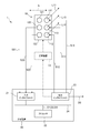
- FIG. 4 shows another configuration example of the sensor system 1.
- the LiDAR sensor unit 10 according to the present example further includes a third light emitting element 113 and a third light receiving element 123.
- the third light emitting element 113 is disposed between the first light emitting element 111 and the second light emitting element 112.
- the third light emitting element 113 is configured to emit the third detection light L13 toward the outside of the vehicle.
- the third detection light L13 is invisible light.
- the invisible light for example, infrared light having a wavelength of 905 nm can be used.
- a semiconductor light emitting element such as a light emitting diode or a laser diode can be used.
- the third light receiving element 123 is disposed between the first light receiving element 121 and the second light receiving element 122.
- the third light receiving element 123 is configured to output a third light receiving signal S23 according to the amount of incident light.
- the third light receiving signal S23 is an example of a third signal.
- the third light receiving element 123 has sensitivity to at least the wavelength of the third detection light L13.
- a photodiode, a phototransistor, a photoresistor, or the like can be used as the third light receiving element 123.
- the third light receiving signal S23 output from the third light receiving element 123 is input to the input interface 21 of the control device 20.
- the processor 22 acquires third data D3 corresponding to the third light receiving signal S23 input to the input interface 21.
- the third data D3 is in a state where it can be used for information processing described later in the processor 22. That is, the input interface 21 has an appropriate circuit configuration for converting the third light receiving signal S23 into the third data D3.
- the processor 22 controls the light emitting operation of the third light emitting element 113 by inputting the third control signal S13 to the third light emitting element 113 via the output interface 23. Specifically, the light amount, light emission timing, light emission repetition frequency, and the like of the third detection light L13 are controlled. By appropriately adjusting the light emission timing and performing light modulation, identification information can be added to the third detection light L13.
- the third detection light L13 emitted from the third light emitting element 113 is reflected by an object located outside the vehicle to generate third reflected light L23.
- the identification information given to the third detection light L13 is reflected on the third reflected light L23.
- the third reflected light L23 enters the third light receiving element 123.
- the third light receiving element 123 outputs a third light receiving signal S23 according to the amount of the third reflected light L23.
- third data D3 associated with the third reflected light L23 is obtained.
- the identification information given to the third detection light L13 is also reflected on the third data D3.
- the processor 22 can obtain the distance to the object associated with the third reflected light L23 based on the time from when the third detection light L13 is emitted to when the third reflected light L23 is detected. In addition to or instead of this, information on attributes such as the material of the object associated with the third reflected light L23 can be acquired based on the difference between the waveforms of the third detected light L13 and the third reflected light L23.
- the LiDAR sensor unit 10 can include a scanning mechanism 13.
- the scanning mechanism 13 includes a first detection light L11, a second detection light L12, and a third detection light along a direction S that intersects the arrangement direction of the first light emitting element 111, the second light emitting element 112, and the third light emitting element 113.
- the emission direction of the light L3 is changed.
- the processor 22 can control the operation of the scanning mechanism 13 via the output interface 23.
- N N sets of first data D1, second data D2, and third data D3 are obtained by repeating the light emitting operation and the light receiving operation N times during one scan. For example, by acquiring distance information to the object described above for the N sets of data sets, information on the shape of the object associated with the first reflected light L21, the second reflected light L22, and the third reflected light L23 is obtained. Can be obtained.
- the processor 22 is configured to be able to output the data D0 including the information on the object located outside the vehicle acquired as described above to the outside via the output interface 23.
- the data D0 is used for further information processing by another processor.
- the processor 22 acquires the first data D1, the second data D2, and the third data D3 as described above (STEP 1).
- the processor 22 determines whether or not there is a light receiving inversion phenomenon (STEP 2). The determination is made between the first data D1 and the third data D3 and between the third data D3 and the second data D2. For example, if it is determined that the first data D1 is based on the third detection light L13 and the third data D3 is based on the first detection light L11 (Y in STEP2), the first data D1 and the first data D1 are determined. The three data D3 are exchanged (STEP 4).
- the first reflected light L21 generated by the first detection light L11 is incident on the first light receiving element 121, and the second reflection light generated by the second detection light L12.
- the light L22 is incident on the second light receiving element 122, and the third reflected light L23 generated by the third detection light L13 is incident on the third light receiving element 123. Therefore, if the first data D1 is generated based on the first reflected light L21, the first data D1 reflects the identification information given to the first detection light L11. If the second data D2 is generated based on the second reflected light L22, the second data D2 reflects the identification information given to the first detection light L11. If the third data D3 is generated based on the third reflected light L23, the identification information given to the third detection light L13 is reflected in the third data D3.
- the processor 22 makes the above determination through detection of the identification information.
- the first data D1 is based on the first detection light L11
- the second data D2 is based on the second detection light L12
- the third data D3 is based on the third detection light L13. Then (N in STEP5 in FIG. 3), as illustrated in FIG. 5A, the first data D1, the second data D2, and the third data D3 are output as they are (STEP3 in FIG. 3). Thereafter, the process returns to STEP1.
- the LiDAR sensor unit 10 when the LiDAR sensor unit 10 is displaced due to, for example, vibration of the vehicle, a situation occurs in which the third reflected light L23 enters both the first light receiving element 121 and the third light receiving element 123. sell.
- the first data D1 generated based on the first light receiving signal S21 output from the first light receiving element 121 reflects the identification signal given to the third detection light L13.
- the identification signal given to the third detection light L13 is reflected in the third data D3 generated based on the third light receiving signal S23 output from the third light receiving element 123. If the first data D1 and the third data D3 are output as they are, the accuracy of the information on the object outside the vehicle obtained by the subsequent processing decreases.
- the processor 22 converts the third data D3 into the average data DA as illustrated in FIG. 5B. (Step 6 in FIG. 3).
- the average data DA is generated by averaging the first data D1 and the second data D2.
- the averaging process is a process of calculating a simple average of the first data D1 and the second data D2.
- the averaging process includes the calculation of the simple average, the calculation of the intermediate value, and the calculation of the mode. It can be any of the calculations.
- the first light receiving element 121, the second light receiving element 122, and the third light receiving element 123 are arranged in a direction corresponding to a vertical direction of the vehicle.
- the vertical component of vehicle vibration is dominant. Therefore, the above-described overlapping phenomenon of light reception is likely to occur between the first light receiving element 121, the second light receiving element 122, and the third light receiving element 123 arranged in a direction corresponding to the vertical direction of the vehicle.
- the processor 22 can perform the above-described averaging process, it is possible to effectively correct the influence of the inversion phenomenon of the light reception that occurs due to the vibration of the vehicle.
- processor 22 may be realized by a general-purpose microprocessor operating in cooperation with a memory, or may be realized by a dedicated integrated circuit such as a microcontroller, an FPGA, or an ASIC.
- Control device 20 can be arranged at any position in the vehicle.
- Control device 20 may be realized by a main ECU or the like that performs central control processing in the vehicle, or may be realized by a sub ECU interposed between main ECU and LiDAR sensor unit 10.
- the first light emitting element 111 and the second light emitting element 112 are arranged in a direction corresponding to the up and down direction of the vehicle.
- the first light receiving element 121 and the second light receiving element 122 are also arranged in a direction corresponding to the vertical direction of the vehicle.
- the first light emitting element 111 and the second light emitting element 112 may be arranged in a direction corresponding to the left-right direction or the front-back direction of the vehicle.
- the first light receiving element 121 and the second light receiving element 122 may also be arranged in a direction corresponding to the left-right direction or the front-back direction of the vehicle.
- the emission directions of the first detection light L11 and the second detection light L12 can be changed by the scanning mechanism 13 to directions corresponding to the up-down direction of the vehicle.
- the LiDAR sensor unit 10 can be replaced with an appropriate sensor unit that can detect information outside the vehicle using a light emitting element and a light receiving element.
- a sensor unit examples include a TOF camera unit and a millimeter-wave radar unit.
- a configuration using a plurality of types of measurement methods may be built in a single sensor unit. The wavelength of the detection light emitted by the light emitting element and the wavelength at which the light receiving element has sensitivity can be appropriately determined according to the measurement technique used.
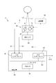
- FIG. 6 illustrates a functional configuration of the sensor system 2 according to the second embodiment.
- the sensor system 2 is mounted on a vehicle.
- the sensor system 2 includes the LiDAR sensor unit 30.
- the LiDAR sensor unit 30 includes a light emitting element 31 and a light receiving element 32.
- the light emitting element 31 is configured to emit the detection light L1 to the outside of the vehicle.
- the detection light L1 is invisible light.
- the invisible light for example, infrared light having a wavelength of 905 nm can be used.
- a semiconductor light emitting element such as a light emitting diode or a laser diode can be used.
- the light receiving element 32 is configured to output a light receiving signal S1 according to the amount of incident light.
- the light receiving element 32 has sensitivity to at least the wavelength of the detection light L1.
- a photodiode, a phototransistor, a photoresistor, or the like can be used as the light receiving element 32.
- the sensor system 2 includes the control device 40.
- the control device 40 includes an input interface 41, a processor 42, an output interface 43, and a communication bus 44.
- the input interface 41, the processor 42, and the output interface 43 can exchange signals and data via a communication bus 44.
- the light receiving signal S1 output from the light receiving element 32 is input to the input interface 41.
- the processor 42 acquires light reception data D11 corresponding to the light reception signal S1 input to the input interface 41.
- the light reception data D11 is in a state where it can be used for information processing described later in the processor 42. That is, the input interface 41 has an appropriate circuit configuration for converting the light receiving signal S1 into light receiving data D11.
- the processor 42 controls the light emitting operation of the light emitting element 31 by inputting the control signal S0 to the light emitting element 31 via the output interface 43. Specifically, the amount of the detection light L1, the light emission timing, the light emission repetition frequency, and the like are controlled.
- the detection light L1 emitted from the light emitting element 31 is reflected by an object located outside the vehicle to generate a reflected light L2.
- the reflected light L2 enters the light receiving element 32.
- the light receiving element 32 outputs a light receiving signal S1 corresponding to the amount of the reflected light L2.
- light reception data D11 associated with the reflected light L2 is obtained.
- the light reception data D11 is an example of data corresponding to information outside the vehicle.
- the processor 42 can acquire the distance to the object associated with the reflected light L2 based on the time from when the detection light L1 is emitted to when the reflected light L2 is detected. In addition to or instead of this, information on attributes such as the material of the object associated with the reflected light L2 can be obtained based on the difference between the waveforms of the detection light L1 and the reflected light L2.
- the LiDAR sensor unit 30 may include a scanning mechanism 33.
- the scanning mechanism 33 changes the emission direction of the detection light L1 along, for example, a direction S crossing the vertical direction of the vehicle.
- the processor 42 can control the operation of the scanning mechanism 33 via the output interface 43.
- NN first data D1 are acquired by repeating the light emitting operation and the light receiving operation N times during one scan. For example, by acquiring distance information to the object described above for the N data sets, it is possible to acquire information on the shape of the object associated with the reflected light L2.
- the processor 42 is configured to be able to output the data D10 including the information of the object located outside the vehicle acquired as described above to the outside via the output interface 43.
- the data D10 is used for further information processing by another processor.
- the sensor system 2 includes the displacement sensor 50.
- the displacement sensor 50 is configured to detect a displacement of the LiDAR sensor unit 30.
- the displacement sensor 50 can be realized by an acceleration sensor or a gyro sensor.
- the displacement sensor 50 is configured to output a displacement signal S2 corresponding to the detected LiDAR sensor unit 30.
- the displacement signal S2 output from the displacement sensor 50 is input to the input interface 41 of the control device 40.
- the processor 42 acquires displacement data D12 corresponding to the displacement signal S2 input to the input interface 41.
- the displacement data D12 is in a state where it can be used for information processing described later in the processor 42. That is, the input interface 41 has an appropriate circuit configuration for converting the displacement signal S2 into the displacement data D12.
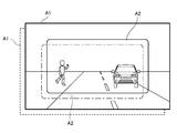
- the area A1 exemplified in FIG. 7A indicates an information detectable area of the LiDAR sensor unit 30.
- the area A2 indicates an area including information output as the data D10 described above.
- the processor 42 extracts a portion corresponding to the area A2 from the acquired light receiving data D11, and generates data D10.
- the LiDAR sensor unit 30 can be displaced from the initial position indicated by the broken line due to vibration of the vehicle or the like.
- the LiDAR sensor unit 30 is displaced in the upper right direction, and the area A1 is also displaced in the upper right direction.
- the position of the object to be detected has moved to the lower left in the area A2. If no countermeasures are taken, information such as the distance to the object may not be obtained accurately.
- the displacement of the LiDAR sensor unit 30 is detected by the displacement sensor 50.
- the processor 42 changes the area A2 to a position where the displacement of the LiDAR sensor unit 30 can be offset based on the displacement data D12 corresponding to the displacement.
- the area A2 has been moved from the initial position indicated by the solid line to the correction position indicated by the dashed line.
- Such a change process is an example of correction of the light reception data D11 based on the displacement data D12.
- Data D10 is generated from the received light data D11 corresponding to the area A2 whose position has been changed in this way, and is output through the output interface 43.
- processor 42 may be realized by a general-purpose microprocessor operating in cooperation with a memory, or may be realized by a dedicated integrated circuit such as a microcontroller, an FPGA, or an ASIC.
- Control device 40 can be arranged at any position in the vehicle.
- Control device 40 may be realized by a main ECU or the like which performs central control processing in the vehicle, or may be realized by a sub ECU interposed between main ECU and LiDAR sensor unit 30.
- the displacement direction of the LiDAR sensor unit 30 that can be detected by the displacement sensor 50 is appropriately determined so as to include the pitch direction, the yaw direction, the roll direction, the horizontal shift direction, and the vertical shift direction. Since the vertical component of the vibration of the vehicle is dominant, the displacement sensor 50 is preferably configured to be able to detect at least the displacement of the LiDAR sensor unit 30 along the vertical direction of the vehicle.
- the LiDAR sensor unit 30 can be replaced with an appropriate sensor unit that can detect information outside the vehicle using a light emitting element and a light receiving element.
- a sensor unit examples include a TOF camera unit and a millimeter-wave radar unit.
- a configuration using a plurality of types of measurement methods may be built in a single sensor unit. The wavelength of the detection light emitted by the light-emitting element and the wavelength at which the light-receiving element has sensitivity can be appropriately determined according to the measurement technique used.
Landscapes
- Engineering & Computer Science (AREA)
- Physics & Mathematics (AREA)
- General Physics & Mathematics (AREA)
- Radar, Positioning & Navigation (AREA)
- Remote Sensing (AREA)
- Computer Networks & Wireless Communication (AREA)
- Electromagnetism (AREA)
- Optical Radar Systems And Details Thereof (AREA)
- Traffic Control Systems (AREA)
Abstract
第一発光素子(111)は、車両の外部へ向けて第一検出光(L11)を出射する。第二発光素子(112)は、車両の外部へ向けて第二検出光(L12)を出射する。第一受光素子(121)は、入射光量に応じた第一受光信号(S21)を出力する。第二受光素子(122)は、入射光量に応じた第二受光信号(S22)を出力する。プロセッサ(42)は、第一受光信号(S21)に対応する第一データ(D1)と第二受光信号(S22)に対応する第二データ(D2)を取得する。第一データ(D1)が第二検出光(L12)に基づくものであり、第二データ(D2)が第一検出光(L11)に基づくものである場合、プロセッサ(42)は、第一データ(D1)と第二データ(D2)を交換する。
Description
本開示は、車両に搭載されるセンサシステムに関する。
車両の運転支援技術を実現するためには、当該車両の外部の情報を検出するためのセンサを車体に搭載する必要がある。そのようなセンサの例としては、LiDAR(Light Detection and Ranging)センサが挙げられる(例えば、特許文献1を参照)。
上記のようなセンサシステムにおいては、車両の振動などに伴う情報取得能力の低下を抑制することが求められている。
上記の要求に応えるための第一態様は、車両に搭載されるセンサシステムであって、
前記車両の外部へ向けて第一検出光を出射する第一発光素子と、
前記車両の外部へ向けて第二検出光を出射する第二発光素子と、
入射光量に応じた第一信号を出力する第一受光素子と、
入射光量に応じた第二信号を出力する第二受光素子と、
前記第一信号に対応する第一データと前記第二信号に対応する第二データを取得するプロセッサと、
を備えており、
前記第一データが前記第二検出光に基づくものであり、前記第二データが前記第一検出光に基づくものである場合、前記プロセッサは、前記第一データと前記第二データを交換する。
前記車両の外部へ向けて第一検出光を出射する第一発光素子と、
前記車両の外部へ向けて第二検出光を出射する第二発光素子と、
入射光量に応じた第一信号を出力する第一受光素子と、
入射光量に応じた第二信号を出力する第二受光素子と、
前記第一信号に対応する第一データと前記第二信号に対応する第二データを取得するプロセッサと、
を備えており、
前記第一データが前記第二検出光に基づくものであり、前記第二データが前記第一検出光に基づくものである場合、前記プロセッサは、前記第一データと前記第二データを交換する。
このような構成によれば、車両の振動などに起因して外部の物体からの反射光が正常に受光素子へ入射されなかった場合においても、正常な受光状態に対応するデータの出力が可能になる。したがって、少なくとも二組の発光素子と受光素子を備えるセンサシステムにおいて、車両の振動などに伴う情報処理能力の低下を抑制できる。
第一態様に係るセンサシステムは、以下のように構成されうる。
前記第一発光素子と前記第二発光素子の間に配置されており、前記車両の外部へ向けて第三検出光を出射する第三発光素子と、
前記第一受光素子と前記第二受光素子の間に配置されており、入射光量に応じた第三信号を出力する第三受光素子と、
を備えており、
前記プロセッサは、前記第三信号に対応する第三データを取得し、
前記第一データと前記第三データの双方が前記第一検出光または前記第三検出光に基づくものである場合、または前記第二データと前記第三データの双方が前記第二検出光または前記第三検出光に基づくものである場合、前記プロセッサは、前記第一データと前記第二データを平均化処理することにより平均データを生成し、前記第三データを当該平均データで置き換える。
前記第一発光素子と前記第二発光素子の間に配置されており、前記車両の外部へ向けて第三検出光を出射する第三発光素子と、
前記第一受光素子と前記第二受光素子の間に配置されており、入射光量に応じた第三信号を出力する第三受光素子と、
を備えており、
前記プロセッサは、前記第三信号に対応する第三データを取得し、
前記第一データと前記第三データの双方が前記第一検出光または前記第三検出光に基づくものである場合、または前記第二データと前記第三データの双方が前記第二検出光または前記第三検出光に基づくものである場合、前記プロセッサは、前記第一データと前記第二データを平均化処理することにより平均データを生成し、前記第三データを当該平均データで置き換える。
このような構成によれば、車両の振動などに起因して外部の物体からの反射光が正常に受光素子へ入射されなかった場合においても、正常な受光状態に近いデータの出力が可能になる。したがって、少なくとも三組の発光素子と受光素子を備えるセンサシステムにおいて、車両の振動などに伴う情報処理能力の低下を抑制できる。
第一態様に係るセンサシステムは、以下のように構成されうる。
前記第一受光素子と前記第二受光素子は、前記車両の上下方向に対応する方向に配列されている。
前記第一受光素子と前記第二受光素子は、前記車両の上下方向に対応する方向に配列されている。
車両の振動は、上下方向の成分が支配的である。したがって、前述した異常な受光は、車両の上下方向に対応する向きに配列された第一受光素子と第二受光素子の間で起こりやすい。しかしながら、プロセッサが上述した第一データと第二データの交換や平均化処理を行ないうるので、車両の振動に起因して発生する受光の反転現象の影響を効果的に補正できる。
第一態様に係るセンサシステムは、以下のように構成されうる。
前記第一発光素子、前記第二発光素子、前記第一受光素子、および前記第二受光素子は、LiDARセンサユニット、TOFカメラユニット、およびミリ波レーダユニットの少なくとも一つの一部である。
前記第一発光素子、前記第二発光素子、前記第一受光素子、および前記第二受光素子は、LiDARセンサユニット、TOFカメラユニット、およびミリ波レーダユニットの少なくとも一つの一部である。
上記の要求に応えるための第二態様は、車両に搭載されるセンサシステムであって、
前記車両の外部の情報を検出するセンサユニットと、
少なくとも前記車両の上下方向に沿う向きの前記センサユニットの変位を検出する変位センサと、
前記変位に対応するデータに基づいて、前記情報に対応するデータを補正するプロセッサと、
を備えている。
前記車両の外部の情報を検出するセンサユニットと、
少なくとも前記車両の上下方向に沿う向きの前記センサユニットの変位を検出する変位センサと、
前記変位に対応するデータに基づいて、前記情報に対応するデータを補正するプロセッサと、
を備えている。
上記のような構成によれば、車両の振動などに起因するセンサユニットの変位が情報検出に与える影響を抑制できる。したがって、車両の振動などに起因するセンサシステムの情報取得能力の低下を抑制できる。
第二態様に係るセンサシステムは、以下のように構成されうる。
前記センサユニットは、LiDARセンサユニット、TOFカメラユニット、およびミリ波レーダユニットの少なくとも一つである。
前記センサユニットは、LiDARセンサユニット、TOFカメラユニット、およびミリ波レーダユニットの少なくとも一つである。
本明細書で用いられる「センサユニット」という語は、所望の情報検出機能を備えつつ、それ自身が単体で流通可能な部品の構成単位を意味する。
本明細書で用いられる「運転支援」という語は、運転操作(ハンドル操作、加速、減速)、走行環境の監視、および運転操作のバックアップの少なくとも一つを少なくとも部分的に行なう制御処理を意味する。すなわち、衝突被害軽減ブレーキ機能やレーンキープアシスト機能のような部分的な運転支援から完全自動運転動作までを含む意味である。
添付の図面を参照しつつ、実施形態の例について以下詳細に説明する。以下の説明に用いる各図面では、各部材を認識可能な大きさとするために縮尺を適宜変更している。
図1は、第一実施形態に係るセンサシステム1の機能的構成を例示している。センサシステム1は、車両に搭載される。
センサシステム1は、LiDARセンサユニット10を備えている。LiDARセンサユニット10は、第一発光素子111、第二発光素子112、第一受光素子121、および第二受光素子122を備えている。
第一発光素子111は、車両の外部へ向けて第一検出光L11を出射可能に構成されている。第一検出光L11は、非可視光である。非可視光としては、例えば波長905nmの赤外光が使用されうる。第一発光素子111としては、発光ダイオードやレーザダイオードなどの半導体発光素子が使用されうる。
第二発光素子112は、車両の外部へ向けて第二検出光L12を出射可能に構成されている。第二検出光L12は、非可視光である。非可視光としては、例えば波長905nmの赤外光が使用されうる。第二発光素子112としては、発光ダイオードやレーザダイオードなどの半導体発光素子が使用されうる。
第一受光素子121は、入射光量に応じた第一受光信号S21を出力するように構成されている。第一受光信号S21は、第一信号の一例である。第一受光素子121は、少なくとも第一検出光L11の波長に感度を有する。第一受光素子121としては、フォトダイオード、フォトトランジスタ、フォトレジスタなどが使用されうる。
第二受光素子122は、入射光量に応じた第二受光信号S22を出力するように構成されている。第二受光信号S22は、第二信号の一例である。第二受光素子122は、少なくとも第二検出光L12の波長に感度を有する。第二受光素子122としては、フォトダイオード、フォトトランジスタ、フォトレジスタなどが使用されうる。
センサシステム1は、制御装置20を備えている。制御装置20は、入力インターフェース21、プロセッサ22、出力インターフェース23、および通信バス24を備えている。入力インターフェース21、プロセッサ22、および出力インターフェース23は、通信バス24を介して信号やデータのやり取りが可能とされている。
第一受光素子121から出力された第一受光信号S21と第二受光素子122から出力された第二受光信号S22は、入力インターフェース21に入力される。
プロセッサ22は、入力インターフェース21に入力された第一受光信号S21と第二受光信号S22にそれぞれ対応する第一データD1と第二データD2を取得する。第一データD1と第二データD2は、プロセッサ22における後述の情報処理に供されうる状態とされている。すなわち、入力インターフェース21は、第一受光信号S21と第二受光信号S22をそれぞれ第一データD1と第二データD2に変換する適宜の回路構成を備えている。
プロセッサ22は、出力インターフェース23を介して第一制御信号S11を第一発光素子111に入力することにより、第一発光素子111の発光動作を制御する。具体的には、第一検出光L11の光量、発光タイミング、発光繰り返し周波数などが制御される。発光タイミングの調節や光変調が適宜になされることにより、第一検出光L11には識別情報が付与されうる。
同様に、プロセッサ22は、出力インターフェース23を介して第二制御信号S12を第二発光素子112に入力することにより、第二発光素子112の発光動作を制御する。具体的には、第二検出光L12の光量、発光タイミング、発光繰り返し周波数などが制御される。発光タイミングの調節や光変調が適宜になされることにより、第二検出光L12には識別情報が付与されうる。
図2Aに示されるように、第一発光素子111から出射された第一検出光L11は、車両の外部に位置する物体により反射され、第一反射光L21が生じる。第一検出光L11に付与された識別情報は、第一反射光L21に反映される。第一反射光L21は、第一受光素子121に入射する。第一受光素子121は、第一反射光L21の光量に応じた第一受光信号S21を出力する。結果として、第一反射光L21に関連付けられた第一データD1が得られる。第一検出光L11に付与された識別情報は、第一データD1にも反映される。
同様に、第二発光素子112から出射された第二検出光L12は、車両の外部に位置する物体により反射され、第二反射光L22が生じる。第二検出光L12に付与された識別情報は、第二反射光L22に反映される。第二反射光L22は、第二受光素子122に入射する。第二受光素子122は、第二反射光L22の光量に応じた第二受光信号S22を出力する。結果として、第二反射光L22に関連付けられた第二データD2が得られる。第二検出光L12に付与された識別情報は、第二データD2にも反映される。
プロセッサ22は、第一検出光L11が出射されてから第一反射光L21が検出されるまでの時間に基づいて、第一反射光L21に関連付けられた物体までの距離を取得できる。これに加えてあるいは代えて、第一検出光L11と第一反射光L21の波形の相違に基づいて、第一反射光L21に関連付けられた物体の材質などの属性に係る情報を取得できる。
同様に、プロセッサ22は、第二検出光L12が出射されてから第二反射光L22が検出されるまでの時間に基づいて、第二反射光L22に関連付けられた物体までの距離を取得できる。これに加えてあるいは代えて、第二検出光L12と第二反射光L22の波形の相違に基づいて、第二反射光L22に関連付けられた物体の材質などの属性に係る情報を取得できる。
図1に例示されるように、LiDARセンサユニット10は、走査機構13を備えうる。走査機構13は、第一発光素子111と第二発光素子112の配列方向と交差する向きSに沿って第一検出光L11と第二検出光L12の出射方向を変化させる。プロセッサ22は、出力インターフェース23を介して走査機構13の動作を制御可能である。
一度の走査中にN回の発光動作と受光動作が繰り返されることにより、N組の第一データD1と第二データD2が取得される。例えば、N組のデータセットについて前述した物体までの距離情報を取得することにより、第一反射光L21と第二反射光L22に関連付けられた物体の形状に係る情報を取得できる。
プロセッサ22は、上記のようにして取得した車両の外部に位置する物体の情報を含むデータD0を、出力インターフェース23を介して外部へ出力可能に構成されている。データD0は、別のプロセッサによるさらなる情報処理に利用される。
図3は、プロセッサ22により行なわれる処理の流れを例示している。まず、プロセッサ22は、前述のようにして第一データD1と第二データD2を取得する(STEP1)。
続いてプロセッサ22は、受光の反転現象の有無を判断する(STEP2)。具体的には、第一データD1が第一検出光L11に基づくものであるかが判断される。同様に、第二データD2が第二検出光L12に基づくものであるかが判断される。
図2Aを参照して説明したように、通常状態においては、第一検出光L11により生じた第一反射光L21は第一受光素子121に入射し、第二検出光L12により生じた第二反射光L22は第二受光素子122に入射するように構成されている。したがって、第一データD1が第一反射光L21に基づいて生成されたものであれば、第一データD1には第一検出光L11に付与された識別情報が反映されている。第二データD2が第二反射光L22に基づいて生成されたものであれば、第二データD2には第一検出光L11に付与された識別情報が反映されている。プロセッサ22は、識別情報の検出を通じて、上記の判断を行なう。
第一データD1が第一検出光L11に基づくものであり、第二データD2が第二検出光L12に基づくものであると判断されると(図3のSTEP2においてN)、図2Aに示されるように、第一データD1と第二データD2がそのまま出力される(図3のSTEP3)。その後、処理はSTEP1に戻る。
図2Bに例示されるように、車両の振動などに起因してLiDARセンサユニット10が変位すると、第一反射光L21が第二受光素子122に入射し、第二反射光L22が第一受光素子121に入射する事態が起こりうる。この場合、第一受光素子121から出力された第一受光信号S21に基づいて生成された第一データD1には、第二検出光L12に付与された識別信号が反映されている。他方、第二受光素子122から出力された第二受光信号S22に基づいて生成された第二データD2には、第一検出光L11に付与された識別信号が反映されている。このまま第一データD1と第二データD2が出力されると、後続する処理によって得られる車両外部の物体に係る情報の正確性が低下する。
したがって、第一データD1が第二検出光L12に基づくものであり、第二データD2が第二検出光L12に基づくものであると判断されると(図3のSTEP2においてY)、プロセッサ22は、図2Bに例示されるように、第一データD1と第二データD2を交換する処理を行なう(図3におけるSTEP4)。続いて、交換がなされた第一データD1と第二データD2が出力される(図3におけるSTEP3)。例えば第一データD1と第二データD2がシリアル出力される場合、第一データD1と第二データD2の出力順序が交換される。例えば第一データD1と第二データD2がパラレル出力される場合、両データに割り当てられる出力ポートのアドレスが交換される。
第一検出光L11と第二検出光L12の出射方向が走査機構13により変更されつつ、一度の走査中にN回の発光動作と受光動作がなされる場合、2行×N列のデータセット(N個の第一データD1とN個の第二データD2からなる集合)が取得される。この場合、第一データD1と第二データD2の交換は、行単位でなされてもよい。すなわちN個の第一データD1全体とN個の第二データD2全体同士が交換されうる。
このような構成によれば、車両の振動などに起因して物体からの反射光が正常に受光素子へ入射されなかった場合においても、正常な受光状態に対応するデータの出力が可能になる。少なくとも二組の発光素子と受光素子を備えるセンサシステムにおいて、車両の振動などに伴う情報処理能力の低下を抑制できる。
本実施形態においては、第一受光素子121と第二受光素子122は、車両の上下方向に対応する向きに配列されている。
車両の振動は、上下方向の成分が支配的である。したがって、前述した受光の反転現象は、車両の上下方向に対応する向きに配列された第一受光素子121と第二受光素子122の間で起こりやすい。しかしながら、プロセッサ22が上述した第一データD1と第二データD2の交換を行ないうるので、車両の振動に起因して発生する受光の反転現象の影響を効果的に補正できる。
図4は、センサシステム1の別構成例を示している。本例に係るLiDARセンサユニット10は、第三発光素子113と第三受光素子123をさらに備えている。
第三発光素子113は、第一発光素子111と第二発光素子112の間に配置されている。第三発光素子113は、車両の外部へ向けて第三検出光L13を出射可能に構成されている。第三検出光L13は、非可視光である。非可視光としては、例えば波長905nmの赤外光が使用されうる。第三発光素子113としては、発光ダイオードやレーザダイオードなどの半導体発光素子が使用されうる。
第三受光素子123は、第一受光素子121と第二受光素子122の間に配置されている。第三受光素子123は、入射光量に応じた第三受光信号S23を出力するように構成されている。第三受光信号S23は、第三信号の一例である。第三受光素子123は、少なくとも第三検出光L13の波長に感度を有する。第三受光素子123としては、フォトダイオード、フォトトランジスタ、フォトレジスタなどが使用されうる。
第三受光素子123から出力された第三受光信号S23は、制御装置20の入力インターフェース21に入力される。プロセッサ22は、入力インターフェース21に入力された第三受光信号S23に対応する第三データD3を取得する。第三データD3は、プロセッサ22における後述の情報処理に供されうる状態とされている。すなわち、入力インターフェース21は、第三受光信号S23を第三データD3に変換する適宜の回路構成を備えている。
プロセッサ22は、出力インターフェース23を介して第三制御信号S13を第三発光素子113に入力することにより、第三発光素子113の発光動作を制御する。具体的には、第三検出光L13の光量、発光タイミング、発光繰り返し周波数などが制御される。発光タイミングの調節や光変調が適宜になされることにより、第三検出光L13には識別情報が付与されうる。
図5Aに例示されるように、第三発光素子113から出射された第三検出光L13は、車両の外部に位置する物体により反射され、第三反射光L23が生じる。第三検出光L13に付与された識別情報は、第三反射光L23に反映される。第三反射光L23は、第三受光素子123に入射する。第三受光素子123は、第三反射光L23の光量に応じた第三受光信号S23を出力する。結果として、第三反射光L23に関連付けられた第三データD3が得られる。第三検出光L13に付与された識別情報は、第三データD3にも反映される。
プロセッサ22は、第三検出光L13が出射されてから第三反射光L23が検出されるまでの時間に基づいて、第三反射光L23に関連付けられた物体までの距離を取得できる。これに加えてあるいは代えて、第三検出光L13と第三反射光L23の波形の相違に基づいて、第三反射光L23に関連付けられた物体の材質などの属性に係る情報を取得できる。
図4に例示されるように、LiDARセンサユニット10は、走査機構13を備えうる。走査機構13は、第一発光素子111、第二発光素子112、および第三発光素子113の配列方向と交差する向きSに沿って第一検出光L11、第二検出光L12、および第三検出光L3の出射方向を変化させる。プロセッサ22は、出力インターフェース23を介して走査機構13の動作を制御可能である。
一度の走査中にN回の発光動作と受光動作が繰り返されることにより、N組の第一データD1、第二データD2、および第三データD3が取得される。例えば、N組のデータセットについて前述した物体までの距離情報を取得することにより、第一反射光L21、第二反射光L22、および第三反射光L23に関連付けられた物体の形状に係る情報を取得できる。
プロセッサ22は、上記のようにして取得した車両の外部に位置する物体の情報を含むデータD0を、出力インターフェース23を介して外部へ出力可能に構成されている。データD0は、別のプロセッサによるさらなる情報処理に利用される。
本例に係るプロセッサ22により行なわれる動作もまた、図3に例示されるフローチャートで説明可能である。まず、プロセッサ22は、前述のようにして第一データD1、第二データD2、および第三データD3を取得する(STEP1)。
続いてプロセッサ22は、受光の反転現象の有無を判断する(STEP2)。当該判断は、第一データD1と第三データD3の間、および第三データD3と第二データD2の間で行なわれる。例えば、第一データD1が第三検出光L13に基づくものであり、第三データD3が第一検出光L11に基づくものであると判断されると(STEP2においてY)、第一データD1と第三データD3の交換がなされる(STEP4)。
本例においては、受光の反転現象がないと判断されると(STEP2においてN)、受光の重複現象の有無が判断される(STEP5)。具体的には、第一データD1と第三データD3の双方が第一検出光L11または第三検出光L13に基づくものであるかが判断される。同様に、第三データD3と第二データD2の双方が第三検出光L13または第二検出光L12に基づくものであるかが判断される。
図5Aを参照して説明したように、通常状態においては、第一検出光L11により生じた第一反射光L21は第一受光素子121に入射し、第二検出光L12により生じた第二反射光L22は第二受光素子122に入射し、第三検出光L13により生じた第三反射光L23は第三受光素子123に入射するように構成されている。したがって、第一データD1が第一反射光L21に基づいて生成されたものであれば、第一データD1には第一検出光L11に付与された識別情報が反映されている。第二データD2が第二反射光L22に基づいて生成されたものであれば、第二データD2には第一検出光L11に付与された識別情報が反映されている。第三データD3が第三反射光L23に基づいて生成されたものであれば、第三データD3には第三検出光L13に付与された識別情報が反映されている。プロセッサ22は、識別情報の検出を通じて、上記の判断を行なう。
第一データD1が第一検出光L11に基づくものであり、第二データD2が第二検出光L12に基づくものであり、第三データD3が第三検出光L13に基づくものであると判断されると(図3のSTEP5においてN)、図5Aに例示されるように、第一データD1、第二データD2、および第三データD3がそのまま出力される(図3のSTEP3)。その後、処理はSTEP1に戻る。
図5Bに例示されるように、車両の振動などに起因してLiDARセンサユニット10が変位すると、第三反射光L23が第一受光素子121と第三受光素子123の双方に入射する事態が起こりうる。この場合、第一受光素子121から出力された第一受光信号S21に基づいて生成された第一データD1には、第三検出光L13に付与された識別信号が反映されている。同様に、第三受光素子123から出力された第三受光信号S23に基づいて生成された第三データD3にも、第三検出光L13に付与された識別信号が反映されている。このまま第一データD1と第三データD3が出力されると、後続する処理によって得られる車両外部の物体に係る情報の正確性が低下する。
したがって、第一データD1と第三データD3の双方が第一検出光L11または第三検出光L13に基づくものであると判断されると、あるいは、第二データD2と第三データD3の双方が第二検出光L12第三検出光L13に基づくものであると判断されると(図3のSTEP5においてY)、プロセッサ22は、図5Bに例示されるように、第三データD3を平均データDAで置き換える処理を行なう(図3のSTEP6)。平均データDAは、第一データD1と第二データD2を平均化処理することによって生成される。
取得された第一データD1、第二データD2、および第三データD3が一組であれば、平均化処理は、第一データD1と第二データD2の単純平均を算出する処理である。走査機構13を用いることにより複数組の第一データD1、第二データD2、および第三データD3が取得される場合、平均化処理は、単純平均の算出、中間値の算出、最頻値の算出のいずれかとされうる。
続いて、置き換えがなされた第一データD1、第二データD2、および平均データDAが出力される(図3におけるSTEP3)。
このような構成によれば、車両の振動などに起因して物体からの反射光が正常に受光素子へ入射されなかった場合においても、正常な受光状態に近いデータの出力が可能になる。したがって、少なくとも三組の発光素子と受光素子を備えるセンサシステムにおいて、車両の振動などに伴う情報処理能力の低下を抑制できる。
本実施形態においては、第一受光素子121、第二受光素子122、および第三受光素子123は、車両の上下方向に対応する向きに配列されている。
車両の振動は、上下方向の成分が支配的である。したがって、前述した受光の重複現象は、車両の上下方向に対応する向きに配列された第一受光素子121、第二受光素子122、および第三受光素子123の間で起こりやすい。しかしながら、プロセッサ22が上述した平均化処理を行ないうるので、車両の振動に起因して発生する受光の反転現象の影響を効果的に補正できる。
これまで説明したプロセッサ22の機能は、メモリと協働して動作する汎用マイクロプロセッサにより実現されてもよいし、マイクロコントローラ、FPGA、ASICなどの専用集積回路によって実現されてもよい。
制御装置20は、車両における任意の位置に配置されうる。制御装置20は、車両における中央制御処理を担うメインECUなどによって実現されてもよいし、メインECUとLiDARセンサユニット10の間に介在するサブECUによって実現されてもよい。
上記の実施形態は、本開示の理解を容易にするための例示にすぎない。上記の実施形態に係る構成は、本開示の趣旨を逸脱しなければ、適宜に変更・改良されうる。
上記の実施形態においては、第一発光素子111と第二発光素子112は、車両の上下方向に対応する向きに配列されている。第一受光素子121と第二受光素子122もまた、車両の上下方向に対応する向きに配列されている。しかしながら、第一発光素子111と第二発光素子112は、車両の左右方向または前後方向に対応する向きに配列されてもよい。第一受光素子121と第二受光素子122もまた、車両の左右方向または前後方向に対応する向きに配列されてもよい。この場合、第一検出光L11と第二検出光L12の出射方向は、走査機構13によって車両の上下方向に対応する向きに変更されうる。
LiDARセンサユニット10は、発光素子と受光素子を用いて車両の外部の情報を検出しうる適宜のセンサユニットで置き換えられうる。そのようなセンサユニットとしては、TOFカメラユニットやミリ波レーダユニットが例示されうる。複数種の測定手法を用いる構成が単一のセンサユニットに内蔵されていてもよい。発光素子により出射される検出光の波長、および受光素子が感度を有する波長は、使用される測定手法に応じて適宜に定められうる。
図6は、第二実施形態に係るセンサシステム2の機能的構成を例示している。センサシステム2は、車両に搭載される。
センサシステム2は、LiDARセンサユニット30を備えている。LiDARセンサユニット30は、発光素子31と受光素子32を備えている。
発光素子31は、車両の外部へ向けて検出光L1を出射可能に構成されている。検出光L1は、非可視光である。非可視光としては、例えば波長905nmの赤外光が使用されうる。発光素子31としては、発光ダイオードやレーザダイオードなどの半導体発光素子が使用されうる。
受光素子32は、入射光量に応じた受光信号S1を出力するように構成されている。受光素子32は、少なくとも検出光L1の波長に感度を有する。受光素子32としては、フォトダイオード、フォトトランジスタ、フォトレジスタなどが使用されうる。
センサシステム2は、制御装置40を備えている。制御装置40は、入力インターフェース41、プロセッサ42、出力インターフェース43、および通信バス44を備えている。入力インターフェース41、プロセッサ42、および出力インターフェース43は、通信バス44を介して信号やデータのやり取りが可能とされている。
受光素子32から出力された受光信号S1は、入力インターフェース41に入力される。プロセッサ42は、入力インターフェース41に入力された受光信号S1に対応する受光データD11を取得する。受光データD11は、プロセッサ42における後述の情報処理に供されうる状態とされている。すなわち、入力インターフェース41は、受光信号S1を受光データD11に変換する適宜の回路構成を備えている。
プロセッサ42は、出力インターフェース43を介して制御信号S0を発光素子31に入力することにより、発光素子31の発光動作を制御する。具体的には、検出光L1の光量、発光タイミング、発光繰り返し周波数などが制御される。
発光素子31から出射された検出光L1は、車両の外部に位置する物体により反射され、反射光L2が生じる。反射光L2は、受光素子32に入射する。受光素子32は、反射光L2の光量に応じた受光信号S1を出力する。結果として、反射光L2に関連付けられた受光データD11が得られる。受光データD11は、車両の外部の情報に対応するデータの一例である。
プロセッサ42は、検出光L1が出射されてから反射光L2が検出されるまでの時間に基づいて、反射光L2に関連付けられた物体までの距離を取得できる。これに加えてあるいは代えて、検出光L1と反射光L2の波形の相違に基づいて、反射光L2に関連付けられた物体の材質などの属性に係る情報を取得できる。
LiDARセンサユニット30は、走査機構33を備えうる。走査機構33は、例えば車両の上下方向に交差する向きSに沿って検出光L1の出射方向を変化させる。プロセッサ42は、出力インターフェース43を介して走査機構33の動作を制御可能である。
一度の走査中にN回の発光動作と受光動作が繰り返されることによって、N個の第一データD1が取得される。例えば、N個のデータセットについて前述した物体までの距離情報を取得することにより、反射光L2に関連付けられた物体の形状に係る情報を取得できる。
プロセッサ42は、上記のようにして取得した車両の外部に位置する物体の情報を含むデータD10を、出力インターフェース43を介して外部へ出力可能に構成されている。データD10は、別のプロセッサによるさらなる情報処理に利用される。
センサシステム2は、変位センサ50を備えている。変位センサ50は、LiDARセンサユニット30の変位を検出するように構成されている。変位センサ50は、加速度センサやジャイロセンサによって実現されうる。変位センサ50は、検出されたLiDARセンサユニット30に応じた変位信号S2を出力するように構成されている。
変位センサ50から出力された変位信号S2は、制御装置40の入力インターフェース41に入力される。プロセッサ42は、入力インターフェース41に入力された変位信号S2に対応する変位データD12を取得する。変位データD12は、プロセッサ42における後述の情報処理に供されうる状態とされている。すなわち、入力インターフェース41は、変位信号S2を変位データD12に変換する適宜の回路構成を備えている。
図7Aに例示される領域A1は、LiDARセンサユニット30の情報検出可能領域を示している。領域A2は、前述したデータD10として出力される情報を含む領域を示している。プロセッサ42は、取得した受光データD11から領域A2に対応する部分を抽出し、データD10を生成する。
車両の振動などに起因して、LiDARセンサユニット30は破線で示される初期位置から変位しうる。図7Bに示される例においては、LiDARセンサユニット30が右上方向に変位し、領域A1もまた右上方向に変位している。その結果、検出に供される物体の位置が領域A2内で左下方向へ移動している。何らの対策もなされない場合、物体までの距離などの情報が正確に得られないおそれがある。
上記のLiDARセンサユニット30の変位は、変位センサ50によって検出される。プロセッサ42は、当該変位に対応する変位データD12に基づいて、LiDARセンサユニット30の変位を相殺しうる位置へ領域A2を変更する。図7Bに例示される例においては、領域A2は、実線で示される当初位置から一点鎖線で示される補正位置へ移動されている。このような変更処理は、変位データD12に基づく受光データD11の補正の一例である。このようにして位置が変更された領域A2に対応する受光データD11からデータD10が生成され、出力インターフェース43を通じて出力される。
上記のような構成によれば、車両の振動などに起因するLiDARセンサユニット30の変位が情報検出に与える影響を抑制できる。したがって、車両の振動などに起因するセンサシステム2の情報取得能力の低下を抑制できる。
これまで説明したプロセッサ42の機能は、メモリと協働して動作する汎用マイクロプロセッサにより実現されてもよいし、マイクロコントローラ、FPGA、ASICなどの専用集積回路によって実現されてもよい。
制御装置40は、車両における任意の位置に配置されうる。制御装置40は、車両における中央制御処理を担うメインECUなどによって実現されてもよいし、メインECUとLiDARセンサユニット30の間に介在するサブECUによって実現されてもよい。
上記の実施形態は、本開示の理解を容易にするための例示にすぎない。上記の実施形態に係る構成は、本開示の趣旨を逸脱しなければ、適宜に変更・改良されうる。
変位センサ50が検出可能なLiDARセンサユニット30の変位方向は、ピッチ方向、ヨー方向、ロール方向、水平シフト方向、垂直シフト方向を含むように適宜定められる。車両の振動は上下方向の成分が支配的であるので、変位センサ50は、少なくとも車両の上下方向に沿うLiDARセンサユニット30の変位を検出可能に構成されることが好ましい。
LiDARセンサユニット30は、発光素子と受光素子を用いて車両の外部の情報を検出しうる適宜のセンサユニットで置き換えられうる。そのようなセンサユニットとしては、TOFカメラユニットやミリ波レーダユニットが例示されうる。複数種の測定手法を用いる構成が単一のセンサユニットに内蔵されていてもよい。発光素子により出射される検出光の波長、および受光素子が感度を有する波長は、使用される測定手法に応じて適宜に定められうる。
本出願の記載の一部を構成するものとして、2018年7月25日に提出された日本国特許出願2018-139517号の内容が援用される。
Claims (6)
- 車両に搭載されるセンサシステムであって、
前記車両の外部へ向けて第一検出光を出射する第一発光素子と、
前記車両の外部へ向けて第二検出光を出射する第二発光素子と、
入射光量に応じた第一信号を出力する第一受光素子と、
入射光量に応じた第二信号を出力する第二受光素子と、
前記第一信号に対応する第一データと前記第二信号に対応する第二データを取得するプロセッサと、
を備えており、
前記第一データが前記第二検出光に基づくものであり、前記第二データが前記第一検出光に基づくものである場合、前記プロセッサは、前記第一データと前記第二データを交換する、
センサシステム。 - 前記第一発光素子と前記第二発光素子の間に配置されており、前記車両の外部へ向けて第三検出光を出射する第三発光素子と、
前記第一受光素子と前記第二受光素子の間に配置されており、入射光量に応じた第三信号を出力する第三受光素子と、
を備えており、
前記プロセッサは、前記第三信号に対応する第三データを取得し、
前記第一データと前記第三データの双方が前記第一検出光または前記第三検出光に基づくものである場合、または前記第二データと前記第三データの双方が前記第二検出光または前記第三検出光に基づくものである場合、前記プロセッサは、前記第一データと前記第二データを平均化処理することにより平均データを生成し、前記第三データを当該平均データで置き換える、
請求項1に記載のセンサシステム。 - 前記第一受光素子と前記第二受光素子は、前記車両の上下方向に対応する方向に配列されている、
請求項1または2に記載のセンサシステム。 - 前記第一発光素子、前記第二発光素子、前記第一受光素子、および前記第二受光素子は、LiDARセンサユニット、TOFカメラユニット、およびミリ波レーダユニットの少なくとも一つの一部である、
請求項1から3のいずれか一項に記載のセンサシステム。 - 車両に搭載されるセンサシステムであって、
前記車両の外部の情報を検出するセンサユニットと、
少なくとも前記車両の上下方向に沿う向きの前記センサユニットの変位を検出する変位センサと、
前記変位に対応するデータに基づいて、前記情報に対応するデータを補正するプロセッサと、
を備えている、
センサシステム。 - 前記センサユニットは、LiDARセンサユニット、TOFカメラユニット、およびミリ波レーダユニットの少なくとも一つである、
請求項5に記載のセンサシステム。
Priority Applications (3)
| Application Number | Priority Date | Filing Date | Title |
|---|---|---|---|
| US17/262,537 US12105204B2 (en) | 2018-07-25 | 2019-07-18 | Sensor system |
| CN201980049488.8A CN112470037B (zh) | 2018-07-25 | 2019-07-18 | 传感器系统 |
| JP2020532340A JP7316277B2 (ja) | 2018-07-25 | 2019-07-18 | センサシステム |
Applications Claiming Priority (2)
| Application Number | Priority Date | Filing Date | Title |
|---|---|---|---|
| JP2018139517 | 2018-07-25 | ||
| JP2018-139517 | 2018-07-25 |
Publications (1)
| Publication Number | Publication Date |
|---|---|
| WO2020022185A1 true WO2020022185A1 (ja) | 2020-01-30 |
Family
ID=69181671
Family Applications (1)
| Application Number | Title | Priority Date | Filing Date |
|---|---|---|---|
| PCT/JP2019/028292 Ceased WO2020022185A1 (ja) | 2018-07-25 | 2019-07-18 | センサシステム |
Country Status (4)
| Country | Link |
|---|---|
| US (1) | US12105204B2 (ja) |
| JP (1) | JP7316277B2 (ja) |
| CN (1) | CN112470037B (ja) |
| WO (1) | WO2020022185A1 (ja) |
Cited By (3)
| Publication number | Priority date | Publication date | Assignee | Title |
|---|---|---|---|---|
| WO2020189062A1 (ja) * | 2019-03-19 | 2020-09-24 | 株式会社デンソー | 測距装置および測距装置における異常判定方法 |
| JP2023534691A (ja) * | 2020-07-14 | 2023-08-10 | インターナショナル・ビジネス・マシーンズ・コーポレーション | ガイド付きマルチスペクトル検査 |
| JP2025534323A (ja) * | 2022-09-28 | 2025-10-15 | ヴァレオ・シャルター・ウント・ゼンゾーレン・ゲーエムベーハー | 超音波トランシーバおよび光学トランシーバ装置を備えるセンサ設備 |
Citations (7)
| Publication number | Priority date | Publication date | Assignee | Title |
|---|---|---|---|---|
| JPH08248133A (ja) * | 1995-03-07 | 1996-09-27 | Omron Corp | 位置情報検出装置、位置情報検出装置を用いた車両搭載用レーダ、および路上障害物認識方法 |
| JPH0996525A (ja) * | 1995-09-29 | 1997-04-08 | Suzuki Motor Corp | 車載用距離測定装置 |
| JPH10209838A (ja) * | 1997-01-22 | 1998-08-07 | Kanazawa Kogyo Univ | 監視システム、測定システムおよび測定装置 |
| JP2007101342A (ja) * | 2005-10-04 | 2007-04-19 | Omron Corp | 距離測定装置 |
| JP2014029317A (ja) * | 2012-07-03 | 2014-02-13 | Ricoh Co Ltd | レーザレーダ装置 |
| JP2016525802A (ja) * | 2013-08-02 | 2016-08-25 | コーニンクレッカ フィリップス エヌ ヴェKoninklijke Philips N.V. | 調節可能な偏光を有するレーザデバイス |
| JP2017166846A (ja) * | 2016-03-14 | 2017-09-21 | 株式会社デンソー | 物体認識装置 |
Family Cites Families (21)
| Publication number | Priority date | Publication date | Assignee | Title |
|---|---|---|---|---|
| JP3223528B2 (ja) * | 1991-07-05 | 2001-10-29 | オムロン株式会社 | 光電センサ |
| JP2697307B2 (ja) * | 1993-06-29 | 1998-01-14 | オムロン株式会社 | 路面判別装置およびその応用装置 |
| AU7082894A (en) | 1993-06-29 | 1995-01-24 | Omron Corporation | Road-surface examining device and device using it |
| JP2008071385A (ja) * | 2006-09-12 | 2008-03-27 | Nidec Sankyo Corp | 光ヘッド装置 |
| JP5151169B2 (ja) * | 2007-01-31 | 2013-02-27 | 株式会社デンソー | 計測装置及び車両制御装置並びに警報装置 |
| CN100573043C (zh) | 2008-03-21 | 2009-12-23 | 哈尔滨工业大学 | 路面平整度自动检测方法 |
| JP5470886B2 (ja) | 2009-02-12 | 2014-04-16 | トヨタ自動車株式会社 | 物体検出装置 |
| JP2013113698A (ja) * | 2011-11-29 | 2013-06-10 | Pioneer Electronic Corp | 赤外線センサ装置および赤外線センサの制御方法 |
| JP2014052347A (ja) * | 2012-09-10 | 2014-03-20 | Denso Corp | レーダ装置 |
| MX2016003587A (es) | 2013-09-24 | 2016-06-02 | Alpha Corp | Sensor optico reflexivo vehicular. |
| CN103983195B (zh) * | 2014-04-28 | 2016-03-23 | 广东工业大学 | 一种高精密光栅尺快速测量装置及其方法 |
| JP2015212647A (ja) * | 2014-05-02 | 2015-11-26 | 株式会社リコー | 物体検出装置及びセンシング装置 |
| WO2016002373A1 (ja) * | 2014-07-03 | 2016-01-07 | シャープ株式会社 | 光反射型センサおよび電子機器 |
| EP3358369A4 (en) | 2015-09-30 | 2019-05-08 | Sony Corporation | INFORMATION PROCESSING DEVICE, INFORMATION PROCESSING PROCESS AND PROGRAM |
| JP6580982B2 (ja) | 2015-12-25 | 2019-09-25 | 日立建機株式会社 | オフロードダンプトラック及び障害物判別装置 |
| JP2017150893A (ja) * | 2016-02-23 | 2017-08-31 | ソニー株式会社 | 測距モジュール、測距システム、および、測距モジュールの制御方法 |
| EP3214402B1 (en) | 2016-03-04 | 2018-11-28 | Yokogawa Electric Corporation | Measuring apparatus for measuring vibration or displacement and method for measuring vibration or displacement |
| JP6519505B2 (ja) * | 2016-03-15 | 2019-05-29 | オムロン株式会社 | 物体検出装置、物体検出方法、及びプログラム |
| KR20170138648A (ko) * | 2016-06-08 | 2017-12-18 | 엘지전자 주식회사 | 차량용 라이다 장치 및 차량 |
| US20180329064A1 (en) * | 2017-05-09 | 2018-11-15 | Stmicroelectronics (Grenoble 2) Sas | Method and apparatus for mapping column illumination to column detection in a time of flight (tof) system |
| CN113466882B (zh) * | 2017-07-05 | 2026-03-24 | 奥斯特公司 | 光测距装置 |
-
2019
- 2019-07-18 WO PCT/JP2019/028292 patent/WO2020022185A1/ja not_active Ceased
- 2019-07-18 US US17/262,537 patent/US12105204B2/en active Active
- 2019-07-18 CN CN201980049488.8A patent/CN112470037B/zh active Active
- 2019-07-18 JP JP2020532340A patent/JP7316277B2/ja active Active
Patent Citations (7)
| Publication number | Priority date | Publication date | Assignee | Title |
|---|---|---|---|---|
| JPH08248133A (ja) * | 1995-03-07 | 1996-09-27 | Omron Corp | 位置情報検出装置、位置情報検出装置を用いた車両搭載用レーダ、および路上障害物認識方法 |
| JPH0996525A (ja) * | 1995-09-29 | 1997-04-08 | Suzuki Motor Corp | 車載用距離測定装置 |
| JPH10209838A (ja) * | 1997-01-22 | 1998-08-07 | Kanazawa Kogyo Univ | 監視システム、測定システムおよび測定装置 |
| JP2007101342A (ja) * | 2005-10-04 | 2007-04-19 | Omron Corp | 距離測定装置 |
| JP2014029317A (ja) * | 2012-07-03 | 2014-02-13 | Ricoh Co Ltd | レーザレーダ装置 |
| JP2016525802A (ja) * | 2013-08-02 | 2016-08-25 | コーニンクレッカ フィリップス エヌ ヴェKoninklijke Philips N.V. | 調節可能な偏光を有するレーザデバイス |
| JP2017166846A (ja) * | 2016-03-14 | 2017-09-21 | 株式会社デンソー | 物体認識装置 |
Cited By (5)
| Publication number | Priority date | Publication date | Assignee | Title |
|---|---|---|---|---|
| WO2020189062A1 (ja) * | 2019-03-19 | 2020-09-24 | 株式会社デンソー | 測距装置および測距装置における異常判定方法 |
| JP2023534691A (ja) * | 2020-07-14 | 2023-08-10 | インターナショナル・ビジネス・マシーンズ・コーポレーション | ガイド付きマルチスペクトル検査 |
| US12430868B2 (en) | 2020-07-14 | 2025-09-30 | International Business Machines Corporation | Guided multi-spectral inspection |
| JP7764101B2 (ja) | 2020-07-14 | 2025-11-05 | インターナショナル・ビジネス・マシーンズ・コーポレーション | ガイド付きマルチスペクトル検査 |
| JP2025534323A (ja) * | 2022-09-28 | 2025-10-15 | ヴァレオ・シャルター・ウント・ゼンゾーレン・ゲーエムベーハー | 超音波トランシーバおよび光学トランシーバ装置を備えるセンサ設備 |
Also Published As
| Publication number | Publication date |
|---|---|
| CN112470037A (zh) | 2021-03-09 |
| US12105204B2 (en) | 2024-10-01 |
| JPWO2020022185A1 (ja) | 2021-08-05 |
| CN112470037B (zh) | 2024-10-25 |
| US20210341622A1 (en) | 2021-11-04 |
| JP7316277B2 (ja) | 2023-07-27 |
Similar Documents
| Publication | Publication Date | Title |
|---|---|---|
| US11125876B2 (en) | Lidar system and method for ascertaining a system state of a lidar system | |
| US10114110B2 (en) | Object detecting device, sensing device, and mobile object device | |
| EP3267227B1 (en) | Object detector, sensing device, and mobile apparatus | |
| US20200064475A1 (en) | Target detecting device and target detecting system | |
| KR20160111030A (ko) | 거리 측정 장치 및 시차 연산 시스템 | |
| JP7316277B2 (ja) | センサシステム | |
| US20240027191A1 (en) | Optical Triangulation Sensor | |
| JP2024072847A (ja) | 測定装置 | |
| JP6186863B2 (ja) | 測距装置及びプログラム | |
| US20060092004A1 (en) | Optical sensor | |
| JP6566198B2 (ja) | 物体検出装置、センシング装置、移動体装置及び物体検出方法 | |
| US20250377445A1 (en) | Lidar sensor | |
| JP2023075170A (ja) | センサ装置 | |
| JP2019090679A (ja) | 対象物検出装置 | |
| US20210262790A1 (en) | Optical Axis Deviation Detecting Device, Target Detection Device, and Movable Body | |
| CN109891264B (zh) | 用于机动车辆的检测装置,驾驶员辅助系统,机动车辆和方法 | |
| JP6390459B2 (ja) | 光軸ずれ検出装置 | |
| JP7329943B2 (ja) | 検出装置及び移動装置 | |
| KR20200106211A (ko) | 검출 장치 | |
| JP7081994B2 (ja) | 測距方法及び測距装置 | |
| JPH06317656A (ja) | 2次元受光回路素子及び光情報入力処理装置 | |
| JP7762089B2 (ja) | 測定装置 | |
| JP2019200649A (ja) | センサデータ生成装置 | |
| JP2019178966A (ja) | センサ装置 | |
| KR20210003878A (ko) | 센서 이미지의 주사점에 의해 광전자 센서의 정렬을 결정하기 위한 방법, 및 광전자 센서 |
Legal Events
| Date | Code | Title | Description |
|---|---|---|---|
| 121 | Ep: the epo has been informed by wipo that ep was designated in this application |
Ref document number: 19841511 Country of ref document: EP Kind code of ref document: A1 |
|
| ENP | Entry into the national phase |
Ref document number: 2020532340 Country of ref document: JP Kind code of ref document: A |
|
| NENP | Non-entry into the national phase |
Ref country code: DE |
|
| 122 | Ep: pct application non-entry in european phase |
Ref document number: 19841511 Country of ref document: EP Kind code of ref document: A1 |