WO2020022065A1 - 保温装置 - Google Patents
保温装置 Download PDFInfo
- Publication number
- WO2020022065A1 WO2020022065A1 PCT/JP2019/027362 JP2019027362W WO2020022065A1 WO 2020022065 A1 WO2020022065 A1 WO 2020022065A1 JP 2019027362 W JP2019027362 W JP 2019027362W WO 2020022065 A1 WO2020022065 A1 WO 2020022065A1
- Authority
- WO
- WIPO (PCT)
- Prior art keywords
- heat
- case
- battery
- heat source
- source body
- Prior art date
Links
Images


Classifications
-
- F—MECHANICAL ENGINEERING; LIGHTING; HEATING; WEAPONS; BLASTING
- F28—HEAT EXCHANGE IN GENERAL
- F28D—HEAT-EXCHANGE APPARATUS, NOT PROVIDED FOR IN ANOTHER SUBCLASS, IN WHICH THE HEAT-EXCHANGE MEDIA DO NOT COME INTO DIRECT CONTACT
- F28D20/00—Heat storage plants or apparatus in general; Regenerative heat-exchange apparatus not covered by groups F28D17/00 or F28D19/00
- F28D20/02—Heat storage plants or apparatus in general; Regenerative heat-exchange apparatus not covered by groups F28D17/00 or F28D19/00 using latent heat
-
- H—ELECTRICITY
- H01—ELECTRIC ELEMENTS
- H01M—PROCESSES OR MEANS, e.g. BATTERIES, FOR THE DIRECT CONVERSION OF CHEMICAL ENERGY INTO ELECTRICAL ENERGY
- H01M10/00—Secondary cells; Manufacture thereof
- H01M10/60—Heating or cooling; Temperature control
- H01M10/61—Types of temperature control
- H01M10/615—Heating or keeping warm
-
- H—ELECTRICITY
- H01—ELECTRIC ELEMENTS
- H01M—PROCESSES OR MEANS, e.g. BATTERIES, FOR THE DIRECT CONVERSION OF CHEMICAL ENERGY INTO ELECTRICAL ENERGY
- H01M10/00—Secondary cells; Manufacture thereof
- H01M10/60—Heating or cooling; Temperature control
- H01M10/65—Means for temperature control structurally associated with the cells
- H01M10/656—Means for temperature control structurally associated with the cells characterised by the type of heat-exchange fluid
- H01M10/6569—Fluids undergoing a liquid-gas phase change or transition, e.g. evaporation or condensation
-
- H—ELECTRICITY
- H01—ELECTRIC ELEMENTS
- H01M—PROCESSES OR MEANS, e.g. BATTERIES, FOR THE DIRECT CONVERSION OF CHEMICAL ENERGY INTO ELECTRICAL ENERGY
- H01M10/00—Secondary cells; Manufacture thereof
- H01M10/60—Heating or cooling; Temperature control
- H01M10/65—Means for temperature control structurally associated with the cells
- H01M10/658—Means for temperature control structurally associated with the cells by thermal insulation or shielding
-
- H—ELECTRICITY
- H01—ELECTRIC ELEMENTS
- H01M—PROCESSES OR MEANS, e.g. BATTERIES, FOR THE DIRECT CONVERSION OF CHEMICAL ENERGY INTO ELECTRICAL ENERGY
- H01M50/00—Constructional details or processes of manufacture of the non-active parts of electrochemical cells other than fuel cells, e.g. hybrid cells
- H01M50/20—Mountings; Secondary casings or frames; Racks, modules or packs; Suspension devices; Shock absorbers; Transport or carrying devices; Holders
- H01M50/204—Racks, modules or packs for multiple batteries or multiple cells
-
- H—ELECTRICITY
- H01—ELECTRIC ELEMENTS
- H01M—PROCESSES OR MEANS, e.g. BATTERIES, FOR THE DIRECT CONVERSION OF CHEMICAL ENERGY INTO ELECTRICAL ENERGY
- H01M50/00—Constructional details or processes of manufacture of the non-active parts of electrochemical cells other than fuel cells, e.g. hybrid cells
- H01M50/20—Mountings; Secondary casings or frames; Racks, modules or packs; Suspension devices; Shock absorbers; Transport or carrying devices; Holders
- H01M50/218—Mountings; Secondary casings or frames; Racks, modules or packs; Suspension devices; Shock absorbers; Transport or carrying devices; Holders characterised by the material
- H01M50/22—Mountings; Secondary casings or frames; Racks, modules or packs; Suspension devices; Shock absorbers; Transport or carrying devices; Holders characterised by the material of the casings or racks
- H01M50/222—Inorganic material
- H01M50/224—Metals
-
- H—ELECTRICITY
- H01—ELECTRIC ELEMENTS
- H01M—PROCESSES OR MEANS, e.g. BATTERIES, FOR THE DIRECT CONVERSION OF CHEMICAL ENERGY INTO ELECTRICAL ENERGY
- H01M50/00—Constructional details or processes of manufacture of the non-active parts of electrochemical cells other than fuel cells, e.g. hybrid cells
- H01M50/20—Mountings; Secondary casings or frames; Racks, modules or packs; Suspension devices; Shock absorbers; Transport or carrying devices; Holders
- H01M50/218—Mountings; Secondary casings or frames; Racks, modules or packs; Suspension devices; Shock absorbers; Transport or carrying devices; Holders characterised by the material
- H01M50/22—Mountings; Secondary casings or frames; Racks, modules or packs; Suspension devices; Shock absorbers; Transport or carrying devices; Holders characterised by the material of the casings or racks
- H01M50/227—Organic material
-
- H—ELECTRICITY
- H01—ELECTRIC ELEMENTS
- H01M—PROCESSES OR MEANS, e.g. BATTERIES, FOR THE DIRECT CONVERSION OF CHEMICAL ENERGY INTO ELECTRICAL ENERGY
- H01M50/00—Constructional details or processes of manufacture of the non-active parts of electrochemical cells other than fuel cells, e.g. hybrid cells
- H01M50/20—Mountings; Secondary casings or frames; Racks, modules or packs; Suspension devices; Shock absorbers; Transport or carrying devices; Holders
- H01M50/271—Lids or covers for the racks or secondary casings
-
- Y—GENERAL TAGGING OF NEW TECHNOLOGICAL DEVELOPMENTS; GENERAL TAGGING OF CROSS-SECTIONAL TECHNOLOGIES SPANNING OVER SEVERAL SECTIONS OF THE IPC; TECHNICAL SUBJECTS COVERED BY FORMER USPC CROSS-REFERENCE ART COLLECTIONS [XRACs] AND DIGESTS
- Y02—TECHNOLOGIES OR APPLICATIONS FOR MITIGATION OR ADAPTATION AGAINST CLIMATE CHANGE
- Y02E—REDUCTION OF GREENHOUSE GAS [GHG] EMISSIONS, RELATED TO ENERGY GENERATION, TRANSMISSION OR DISTRIBUTION
- Y02E60/00—Enabling technologies; Technologies with a potential or indirect contribution to GHG emissions mitigation
- Y02E60/10—Energy storage using batteries
-
- Y—GENERAL TAGGING OF NEW TECHNOLOGICAL DEVELOPMENTS; GENERAL TAGGING OF CROSS-SECTIONAL TECHNOLOGIES SPANNING OVER SEVERAL SECTIONS OF THE IPC; TECHNICAL SUBJECTS COVERED BY FORMER USPC CROSS-REFERENCE ART COLLECTIONS [XRACs] AND DIGESTS
- Y02—TECHNOLOGIES OR APPLICATIONS FOR MITIGATION OR ADAPTATION AGAINST CLIMATE CHANGE
- Y02E—REDUCTION OF GREENHOUSE GAS [GHG] EMISSIONS, RELATED TO ENERGY GENERATION, TRANSMISSION OR DISTRIBUTION
- Y02E60/00—Enabling technologies; Technologies with a potential or indirect contribution to GHG emissions mitigation
- Y02E60/14—Thermal energy storage
Definitions
- the present disclosure relates to a heat retention device that keeps a heat source body warm.
- Patent Literature 1 describes a battery heat insulating material for preventing battery cooling in winter.
- a base material in which heat storage particles are dispersed is formed into a shape that encloses a battery and used.
- the present disclosure has been made in view of the above circumstances, and aims to improve the heat retaining property of a heat source body.
- a heat retention device includes a heat source body, a case, and a heat radiation amount reducing unit.
- the case fixes and accommodates the heat source so that a space is formed between the case and the heat source.
- the heat radiation amount reducing unit reduces the amount of heat released from the heat source to the case via the space.
- the amount of heat released from the heat source body to the case via the space is reduced by providing the heat radiation amount reducing unit. For this reason, the heat insulation of the heat source can be enhanced, and the heat insulation of the heat source can be improved.
- FIG. 1 is an overall configuration diagram illustrating a vehicle battery temperature control device according to a first embodiment. It is a schematic sectional view showing the battery pack in a 1st embodiment. It is a graph which shows the relationship between the thickness in an air layer, and thermal resistance.
- FIG. 2 is a circuit diagram illustrating an electric circuit according to the first embodiment. It is a graph which shows the relationship between the elapsed time after vehicle stop and the battery average temperature in 1st Embodiment. 4 is a graph comparing the amount of heat required for warming up a battery between the first embodiment and a comparative example. 5 is a graph showing the relationship between battery temperature, battery output, and internal resistance in a lithium ion battery. It is an outline sectional view showing the battery pack in a 2nd embodiment.
- the vehicle battery temperature controller 1 shown in FIG. 1 is a battery temperature controller that adjusts the batteries 41 and 42 mounted on the vehicle to an appropriate temperature.
- the vehicle battery temperature controller 1 is also an air conditioner that adjusts the interior space of the vehicle to an appropriate temperature.
- the vehicle battery temperature control device 1 is mounted on an electric vehicle that obtains a driving force for driving the vehicle from an electric motor for driving.
- the vehicle battery temperature control device 1 may be mounted on a hybrid vehicle that obtains a driving force for driving the vehicle from an engine (in other words, an internal combustion engine) and a driving electric motor.
- the batteries 41 and 42 mounted on the vehicle can be charged with electric power supplied from an external power supply (in other words, a commercial power supply) when the vehicle stops.
- an external power supply in other words, a commercial power supply
- the batteries 41 and 42 for example, lithium ion batteries can be used.
- the electric power stored in the battery is supplied not only to the electric motor for traveling but also to various in-vehicle devices such as electric components constituting the battery temperature controller 1 for vehicles.
- the vehicle battery temperature controller 1 has a refrigeration cycle device 10.
- the refrigeration cycle apparatus 10 is a vapor compression refrigerator including a compressor 11, a condenser 12, an expansion valve 13, an air cooling evaporator 14, a constant pressure valve 15, and a cooling water cooling evaporator 16.
- a chlorofluorocarbon-based refrigerant is used as the refrigerant, and a subcritical refrigeration cycle in which the high-pressure side refrigerant pressure does not exceed the critical pressure of the refrigerant is configured.
- the compressor 11 is an electric compressor driven by electric power supplied from a battery, and sucks, compresses, and discharges the refrigerant of the refrigeration cycle device 10.
- the condenser 12 is a high-pressure heat exchanger that condenses the high-pressure refrigerant by exchanging heat between the high-pressure refrigerant discharged from the compressor 11 and the cooling water in the high-temperature cooling water circuit 20.
- the cooling water in the high-temperature cooling water circuit 20 is a fluid as a heat medium.
- the cooling water in the high-temperature cooling water circuit 20 is a high-temperature heat medium.
- a liquid containing at least ethylene glycol, dimethylpolysiloxane, or a nanofluid, or an antifreeze liquid is used as the cooling water of the high-temperature cooling water circuit 20.
- the high-temperature cooling water circuit 20 is a high-temperature heat medium circuit in which a high-temperature heat medium circulates.
- the expansion valve 13 is a decompression unit that decompresses and expands the liquid-phase refrigerant flowing out of the condenser 12.
- the expansion valve 13 is a mechanical temperature expansion valve.
- the mechanical expansion valve is a temperature-type expansion valve that has a temperature sensing part and drives a valve body by a mechanical mechanism such as a diaphragm.
- the air cooling evaporator 14 is a refrigerant air heat exchanger that exchanges heat between the refrigerant flowing out of the expansion valve 13 and the air blown into the vehicle interior to cool the air blown into the vehicle interior. In the air cooling evaporator 14, the refrigerant absorbs heat from the air blown into the vehicle interior.
- the constant pressure valve 15 is a pressure adjusting unit (in other words, a pressure adjusting pressure reducing unit) that maintains the pressure of the refrigerant at the outlet side of the air cooling evaporator 14 at a predetermined value.
- the constant pressure valve 15 is constituted by a mechanical variable throttle mechanism. Specifically, when the pressure of the refrigerant at the outlet side of the air cooling evaporator 14 falls below a predetermined value, the constant pressure valve 15 decreases the passage area of the refrigerant passage (that is, the throttle opening). When the pressure of the refrigerant at the outlet side of the air cooling evaporator 14 exceeds a predetermined value, the constant pressure valve 15 increases the passage area of the refrigerant passage (that is, the throttle opening).
- a fixed throttle composed of an orifice, a capillary tube, or the like may be used instead of the constant pressure valve 15.
- the cooling water cooling evaporator 16 is disposed in parallel with the air cooling evaporator 14 and the constant pressure valve 15 in the flow of the refrigerant.
- the cooling water cooling evaporator 16 is a low pressure side heat exchanger that evaporates the low pressure refrigerant by exchanging heat between the low pressure refrigerant flowing out of the expansion valve 13 and the cooling water of the low temperature cooling water circuit 30.
- the gas-phase refrigerant evaporated by the cooling water cooling evaporator 16 is drawn into the compressor 11 and compressed.
- the cooling water in the low-temperature cooling water circuit 30 is a fluid as a heat medium.
- the cooling water in the low-temperature cooling water circuit 30 is a low-temperature heat medium.
- a liquid containing at least ethylene glycol, dimethylpolysiloxane, or a nanofluid, or an antifreeze liquid is used as the cooling water of the low-temperature cooling water circuit 30.
- the low-temperature cooling water circuit 30 is a low-temperature heat medium circuit in which a low-temperature heat medium circulates.
- the high-temperature cooling water circuit 20 has a high-temperature side circulation flow path 20a.
- the high temperature side circulation channel 20a is a cooling water channel through which the high temperature side cooling water circulates.
- the high temperature side pump 21, the heater core 22, the condenser 12, and the high temperature side radiator 24 are arranged in the high temperature side circulation flow path 20a.
- the high temperature side pump 21 is a heat medium pump that sucks and discharges cooling water.
- the high temperature side pump 21 is an electric pump.
- the high-temperature side pump 21 is a high-temperature side flow rate adjustment unit that adjusts the flow rate of the cooling water circulating in the high-temperature cooling water circuit 20.
- the heater core 22 is an air heating heat exchanger that exchanges heat between the cooling water of the high-temperature cooling water circuit 20 and the air blown into the vehicle interior to heat the air blown into the vehicle interior.
- the cooling water radiates heat to the air blown into the vehicle interior.
- the air cooling evaporator 14 and the heater core 22 are housed in an air conditioning casing (not shown).
- the heater core 22 is disposed downstream of the air cooling evaporator 14 in the air passage in the air passage in the air conditioning casing.
- the inside air and the outside air are switched and introduced into the air conditioning casing.
- the inside air and outside air introduced into the air conditioning casing are blown to the air cooling evaporator 14 and the heater core 22 by a blower (not shown).
- An air mix door (not shown) is arranged between the air cooling evaporator 14 and the heater core 22 in the air passage in the air conditioning casing.
- the air mix door adjusts the ratio of the amount of cold air flowing into the heater core 22 and the amount of cold air flowing bypassing the heater core 22 among the cool air that has passed through the evaporator 14 for cooling air.
- the high-temperature radiator 24 is a high-temperature heat medium outside air heat exchanger that exchanges heat between the cooling water of the high-temperature cooling water circuit 20 and the outside air.
- the low-temperature cooling water circuit 30 has a low-temperature side circulation channel 30a.
- the low temperature side circulation channel 30a is a channel through which the low temperature side cooling water circulates.
- a low-temperature side pump 31, a cooling water cooling evaporator 16, a low-temperature side electric heater 32, an inverter 33, a motor generator 34, and a low-temperature side radiator 35 are arranged in the low-temperature side circulation channel 30a.
- the low temperature side pump 31 is a heat medium pump that sucks and discharges cooling water.
- the low temperature side pump 31 is an electric pump.
- the low-temperature electric heater 32 is an auxiliary heater that generates heat when supplied with electric power and heats the cooling water of the low-temperature cooling water circuit 30.
- the inverter 33 converts the DC power supplied from the first battery 41 and the second battery 42 into AC power and outputs the AC power to the motor generator 34.
- Each of the first battery 41 and the second battery 42 is an assembled battery including a plurality of battery cells.
- the motor generator 34 generates driving power for traveling by using the electric power output from the inverter 33, and generates regenerative electric power during deceleration or downhill.
- the temperature of the inverter 33 and the motor generator 34 is adjusted by the cooling water in the low-temperature cooling water circuit 30 to be within a proper temperature range in which sufficient performance can be exhibited.
- the low-temperature radiator 35 is a low-temperature heat medium outside air heat exchanger that exchanges heat between the cooling water in the low-temperature cooling water circuit 30 and the outside air.
- the low-temperature radiator 35 is a heat exchange unit in which the cooling water in the low-temperature cooling water circuit 30 exchanges heat.
- the first battery 41 is arranged in the low temperature side circulation channel 30a.
- the temperature of the first battery 41 is adjusted by the cooling water flowing through the low-temperature side circulation channel 30a.
- the low-temperature side circulation channel 30a is a temperature adjustment unit that adjusts the temperature of the first battery 41 with cooling water.
- the low temperature side circulation channel 30a is a cooling unit that cools the first battery 41 with cooling water.
- the second battery 42 is not arranged in the low temperature side circulation channel 30a.
- the first battery 41 includes a plurality of battery modules 50.
- Each battery module 50 is configured by a laminate in which a plurality of rectangular parallelepiped battery cells (not shown) are laminated.
- the battery module 50 is a heat source that generates heat as it is charged and discharged.
- Each battery cell of the battery module 50 is a chargeable / dischargeable secondary battery (in this embodiment, a lithium ion battery).
- a chargeable / dischargeable secondary battery in this embodiment, a lithium ion battery.
- the temperature of each battery cell needs to be adjusted within a proper temperature range (for example, 10 ° C. or more and 40 ° C. or less) in which sufficient performance can be exhibited.
- the battery module 50 is housed in the case 61 to form the battery pack 60.
- one battery module 50 is housed in one case 61.
- the battery pack 60 according to the present embodiment will be described with reference to FIG.
- the case 61 is an accommodating portion for fixing and accommodating the battery module 50 so that a space is formed between the case 61 and the battery module 50.
- resin aluminum, stainless steel, iron, copper, or the like is used.
- the material of the case 61 is most preferably an aluminum-plated resin.
- the case 61 is configured by combining the main body 611 and the lid member 612.
- the main body 611 is formed in a box shape having an opening on the upper side.
- the lid member 612 is formed so as to close the opening of the main body 611.
- a cooler 62 is provided outside the battery module 50.
- the cooler 62 is provided below the battery module 50.
- the cooler 62 is configured so that cooling water circulating in the low-temperature side circulation channel 30a flows.
- the cooler 62 is a cooling unit that cools the battery module 50 (that is, the first battery 41) with cooling water.
- a flat plate-shaped end plate 63 for holding the battery module 50 and the cooler 62 is provided on the left and right surfaces of the battery module 50 and the cooler 62, respectively.
- a heat storage material 64 is provided outside the battery module 50. More specifically, the heat storage material 64 is provided on the upper surface and front and rear surfaces of the battery module 50, the lower surface of the cooler 62, and the outer surface of the end plate 63 (that is, the surface opposite to the battery module 50 and the cooler 62). Have been.
- Each surface of the battery module 50 (that is, upper and lower surfaces, left and right surfaces, and front and rear surfaces) is covered with the heat storage material 64. In other words, the entire surface of the battery module 50 is covered with the heat storage material 64.
- the heat storage material 64 is a latent heat storage material that stores or radiates heat by utilizing the inflow and outflow of latent heat accompanying a phase change.
- a resin heat storage material containing a microcapsule latent heat storage material is used as the heat storage material 64.
- the microcapsule latent heat storage material is a heat storage material in which the latent heat storage material is enclosed in the microcapsule.
- a latent heat storage material having an entrance / exit temperature of the latent heat of 0 ° C. or less can be used.
- a latent heat storage material for example, a paraffin-based hydrocarbon, hydrate-based, metal-based, or water-based latent heat storage material can be used.
- a space is formed between each surface of the battery module 50 and the case 61. Specifically, a space is formed between the surface of the heat storage material 64 covering the entire surface of the battery module 50 and the inner wall surface of the case 61. In this space, air as gas exists. Note that a heat insulating material may be provided in a part of this space.
- the maximum distance between each surface of the battery module 50 and the case 61 is set to be equal to or less than a predetermined distance at which convection of air on the surface of the battery module 50 is suppressed.
- the maximum distance between each surface of the battery module 50 and the inner wall surface facing each surface of the battery module 50 in the case 61 is a predetermined distance at which the convection of air on the surface of the battery module 50 is suppressed. It is set to be less than the distance.
- the predetermined distance at which convection of air on the surface of the battery module 50 is suppressed is referred to as a convection suppression distance.
- the entire surface of the battery module 50 is covered with the heat storage material 64.
- the maximum distance Dm between the surface of each heat storage material 64 covering each surface of the battery module 50 and the inner wall surface of the case 61 facing the surface of the heat storage material 64 is equal to or less than the convection suppression distance. It is set as follows.
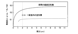
- the relationship between the thickness in the air layer and the thermal resistance is shown in FIG.
- the thermal resistance of the air layer is substantially constant. Therefore, for example, 1.5 cm can be adopted as the convection suppression distance.
- the maximum distance between each surface of the battery module 50 and the inner wall surface of the case 61 facing each surface of the battery module 50 is set to 1.5 cm or less.
- the maximum distance Dm between the surface of each heat storage material 64 covering each surface of the battery module 50 and the inner wall surface of the case 61 facing the surface of each heat storage material 64 is 1. It is set to 5 cm or less.
- the maximum distance Dm between the surface of the heat storage material 64 covering the upper surface of the battery module 50 and the inner wall surface of the case 61 facing the surface of the heat storage material 64 is referred to as the upper maximum distance Dma.
- the maximum distance Dm between the surface of the heat storage material 64 covering the lower surface of the cooler 62 and the inner wall surface of the case 61 facing the surface of the heat storage material 64 is referred to as a lower maximum distance Dmb.
- the surface of the end plate 63 opposite to the bonding surface with the battery module 50 is referred to as a side surface 63a.
- the maximum distance Dm between the side surface 63a of the end plate 63 and the surface of the case 61 facing the side surface 63a is referred to as a maximum lateral distance Dmc.
- the upper maximum distance Dma, the lower maximum distance Dmb, and the lateral maximum distance Dmc are set to the same length.
- connection portion 65 for fixing the battery module 50 covered with the heat storage material 64 at a distance from the inner wall surface on the lower side of the case 61 is provided in the case 61.
- the connection portion 65 of the present embodiment is formed in a rod shape extending from the inner wall surface on the lower side of the case 61 toward the battery module 50 side.
- the thickness of the heat storage material 64 is referred to as t ts .
- the gap between the heat storage material 64 and the case 61 facing the heat storage material 64 is referred to as t air .
- the thickness t ts of the heat storage material 64 is set to be not more than 3 of the gap size t air between the heat storage material 64 and the case 61. Further, the thickness dimension t ts of the heat storage material 64 may be 1 mm.
- the supply of power from the first battery 41 to the inverter 33 and the motor generator 34 is interrupted by a first switch 47a.
- the supply of power from the second battery 42 to the inverter 33 and the motor generator 34 is interrupted by a second switch 48a.
- the battery capacity of each battery cell of the second battery 42 is smaller than the battery capacity of each battery cell of the first battery 41.
- the number of each battery cell of the second battery 42 is the same as the number of each battery cell of the first battery 41. Therefore, the battery capacity of the second battery 42 is smaller than the battery capacity of the first battery 41.
- the electric circuit 70 including the first battery 41, the second battery 42, the inverter 33, and the motor generator 34 includes a DC inlet 71, a charger 72, a DCDC converter 73, and the like.
- the DC inlet 71 is connected to a plug of the DC charging stand 74 when the first battery 41 and the second battery 42 are charged by the DC charging stand 74.
- the plug of the charger 72 is connected to the household outlet 75 when the first battery 41 and the second battery 42 are charged with household power.
- the DCDC converter 73 converts the voltage of the power supplied from the first battery 41 and the second battery 42 to 12 V, and supplies the converted voltage to an auxiliary device 76 mounted on the vehicle.
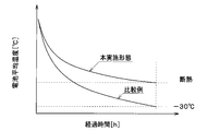
- FIG. 5 is a graph showing the relationship between the elapsed time after stopping the vehicle and the average battery temperature.
- the heat storage material was not provided in the battery, and no space was formed between each surface of the battery module 50 and the case 61.
- the amount of temperature decrease with respect to the elapsed time can be reduced as compared with the comparative example.
- FIG. 6 is a graph comparing the amount of heat required for warming up the battery between the embodiment and the comparative example.
- the amount of heat required for warming up the battery can be reduced as compared with the comparative example.
- FIG. 7 is a graph showing the relationship between battery temperature, battery output, and internal resistance in a lithium ion battery.
- a high output is obtained with a small capacity battery in a low temperature range, and a high output is obtained with a large capacity battery in an intermediate temperature range. In a high temperature range, the life of the battery is shortened.
- the battery in consideration of such characteristics of the lithium ion battery, the battery is operated according to the environmental temperature, the battery temperature, and the remaining battery level, so that the small capacity battery can be used all year without waste.
- a space is formed between each surface of the battery module 50 and the case 61. Then, air exists as a gas in the space formed between each surface of the battery module 50 and the case 61.
- the maximum distance Dm between each surface of the battery module 50 and the case 61 is set to be equal to or less than the convection suppression distance.
- the maximum distance Dm between the surface of the heat storage material 64 covering each surface of the battery module 50 and the inner wall surface of the case 61 facing the surface of the heat storage material 64 is defined as the convection suppression distance (for example, 1). .5 cm) or less.
- the space formed between each surface of the battery module 50 and the case 61 suppresses the convection of air on the surface of the battery module 50, and the amount of heat released from the battery module 50 to the case 61 via the space. Can be reduced. For this reason, since the heat insulation of the battery module 50 which is a heat source can be improved, the heat retention of the battery module 50 can be improved.
- the space formed between each surface of the battery module 50 and the case 61 in the present embodiment constitutes a convection suppressing portion and a heat radiation amount reducing portion.
- the case 61 that is a space forming part that forms the space is a member that forms the convection suppressing part and the heat radiation amount reducing part.
- the heat storage material 64 is provided outside the battery module 50. According to this, the heat generated in the battery module 50 can be stored in the heat storage material 64. When the outside air temperature (that is, the environmental temperature) decreases, the heat stored in the heat storage material 64 is released to the battery module 50, so that the temperature of the battery module 50 can be prevented from lowering. Thereby, the heat retention of the battery module 50 can be improved.
- a latent heat storage material is used as the heat storage material 64. According to this, when the environmental temperature is higher than the melting point of the latent heat storage material, heat is not stored in the heat storage material 64, so that the battery pack 60 of the present embodiment can be used as it is even at a high outside temperature such as summer. It becomes possible.
- the lower end of the end plate 63 projects downward from the lower end surface of the cooler 62.
- the lower end of the end plate 63 is connected to the inner wall surface on the lower side of the case 61.
- a space is formed between the lower surface of the cooler 62 and the case 61.
- the maximum distance between the upper surface of the battery module 50 and the inner wall surface of the case 61 facing the upper surface of the battery module 50 is referred to as an upper maximum distance Dma.
- the maximum distance between the lower surface of the cooler 62 and the inner wall surface of the case 61 facing the lower surface of the cooler 62 is referred to as a lower maximum distance Dmb.
- the maximum distance between the side surface 63a of the end plate 63 and the surface of the case 61 facing the side surface 63a of the end plate 63 is referred to as a maximum lateral distance Dmc.
- the upper maximum distance Dma, the lower maximum distance Dmb, and the lateral maximum distance Dmc are each set to be equal to or less than the convection suppression distance. Furthermore, in the present embodiment, the upper maximum distance Dma is set to be longer than the lateral maximum distance Dmc, and the lower maximum distance Dmb is set to be shorter than the lateral maximum distance Dmc.
- the configuration of the battery module 50 is changed from the first embodiment. Specifically, the heat storage material 64 that covers the outside of the battery module 50 is eliminated, and the insulating plate 53 that is a part of the constituent members of the battery module 50 is formed of the heat storage material.
- the battery module 50 includes a battery cell 51, a frame 52, an insulating plate 53, and the like.
- the battery cell 51 is a heat source that generates heat as it is charged and discharged.
- the plurality of battery cells 51 are stacked in the front-rear direction to form a stacked body 510.
- the frame 52 is made of metal.
- the frame body 52 is formed in a square tubular shape so as to cover the left and right surfaces and the front and rear surfaces of the stacked body 510 of the battery cells 51. Openings (not shown) are formed on the upper and lower surfaces of the frame 52.
- the frame body 52 is formed by combining two first metal members 521 and two second metal members 522.
- the first metal member 521 is a rectangular plate-shaped member.
- the first metal member 521 is formed so as to cover the front and rear surfaces of the stacked body 510 of the battery cell 51.
- the second metal member 522 has a U-shaped cross section perpendicular to the vertical direction (in other words, a bathtub shape).
- the second metal member 522 is formed to cover the stacked body 510 of the battery cell 51 from the left side and the right side.
- the first metal member 521 and the second metal member 522 are integrally connected by a fastening member such as a screw.
- the insulating plate 53 is an insulating member provided between the stacked body 510 of the battery cell 51 and the case 61.
- the insulating plate 53 is made of a resin heat storage material containing a microcapsule heat storage material. For this reason, the insulating plate 53 has a heat storage material at least partially. That is, the insulating plate 53 has a heat storage function.
- microcapsule heat storage material As the microcapsule heat storage material, the same microcapsule latent heat storage material as in the first embodiment can be employed.
- the insulating plate 53 is formed in a rectangular plate shape.
- the insulating plates 53 are arranged one by one so as to cover each surface (ie, upper and lower surfaces, left and right surfaces, and front and rear surfaces) of the stacked body 510 of the battery cells 51.
- first insulating plates 531 two first insulating plates 531, two second insulating plates 532, and two third insulating plates 533 are provided as the insulating plates 53.
- the first insulating plate 531 is arranged so as to cover the front surface and the rear surface of the stacked body 510 of the battery cell 51, respectively.
- the second insulating plate 532 is arranged so as to cover the left surface and the right surface of the stacked body 510 of the battery cell 51, respectively.
- the third insulating plate 533 is disposed so as to cover the upper surface and the lower surface of the stacked body 510 of the battery cell 51, respectively.
- the first insulating plate 531 and the second insulating plate 532 are arranged inside the frame 52. That is, the first insulating plate 531 and the second insulating plate 532 are arranged between the stacked body 510 of the battery cell 51 and the frame 52. Thereby, the battery cell 51 and the frame 52 are insulated from each other.
- the third insulating plate 533 is arranged so as to close the openings formed on the upper and lower surfaces of the frame 52.
- the insulating plate 53 which is a part of the components of the battery module 50, is formed of a heat storage material. According to this, since it is not necessary to separately provide a heat storage material outside the battery module 50, the number of components does not increase. Therefore, the heat retention of the battery module 50 can be improved while reducing the manufacturing cost.
- the lower end of the end plate 63 projects downward from the lower end surface of the cooler 62.
- the lower end of the end plate 63 is connected to the inner wall surface on the lower side of the case 61.
- a space is formed between the lower surface of the cooler 62 and the case 61.
- the maximum distance between the lower surface of the cooler 62 and the inner wall surface of the case 61 facing the lower surface of the cooler 62 is referred to as a maximum lower distance Dmb.
- the upper maximum distance Dma, the lower maximum distance Dmb, and the lateral maximum distance Dmc are each set to be equal to or less than the convection suppression distance. Further, in the present embodiment, the upper maximum distance Dma and the lateral maximum distance Dmc are set to be the same length, and the lower maximum distance Dmb is set shorter than the upper maximum distance Dma and the lateral maximum distance Dmc.
- a plurality of (eight in this example) battery modules 50 are housed in a case 61.
- the heat storage material 64 is arranged so as to cover all of the plurality of battery modules 50.
- the maximum distance Dm between each surface of the heat storage material 64 and the inner wall surface facing each surface of the heat storage material 64 in the case 61 is set to be equal to or less than the convection suppression distance.
- the heat storage material 64 is arranged so as to cover all of the plurality of battery modules 50 in one case 61. Therefore, the number of heat storage materials 64 can be reduced as compared with the case where heat storage materials 64 are arranged so as to cover each battery module 50 one by one. Therefore, the heat retention of the plurality of battery modules 50 can be improved while suppressing an increase in the number of components.
- a plurality of (two in this example) battery modules 50 are set as one set, and the heat storage material 64 is arranged so as to cover the set of battery modules 50 collectively.
- the case 61 a plurality of sets (four in this example) of one set of battery modules 50 covered with the heat storage material 64 are arranged. That is, a plurality of heat storage materials 64 configured to cover one set of battery modules 50 are arranged in the case 61.
- the maximum distance Dm between each surface of the plurality of heat storage materials 64 facing the case 61 and the inner wall surface of the case 61 is set to be equal to or less than the convection suppression distance.
- a plate member 67 facing at least the surface of the battery module 50 is provided in the space inside the case 61.
- the plate member 67 is arranged so as to cover the surface of the battery module 50.
- the plate-shaped member 67 is arranged with a space between the battery module 50 and the battery module 50 so as not to contact the battery module 50.
- the plate member 67 is made of metal (aluminum in this example). In the present embodiment, the plate member 67 is formed integrally with a part of the case 61.
- the plate-shaped member 67 has an upper surface portion 671 facing the upper surface of the battery module 50 and a side surface portion 672 facing the side surface 63a of the end plate 63.
- the maximum distance between the upper surface of the battery module 50 and the upper surface 671 of the plate member 67 is referred to as an upper first maximum distance Dma1.
- the maximum distance between the upper surface 671 of the plate member 67 and the cover member 612 of the case 61 is referred to as an upper second maximum distance Dma2.
- the maximum distance between the side surface 63a of the end plate 63 and the side surface portion 672 of the plate member 67 is referred to as a first lateral maximum distance Dmc1.
- the maximum distance between the side surface portion 672 of the plate member 67 and the inner wall surface of the case 61 facing the side surface portion 672 is referred to as a second maximum lateral distance Dmc2.
- the upper first maximum distance Dma1, the lower maximum distance Dmb, and the first lateral maximum distance Dmc1 are each set to be less than or equal to the convection suppression distance. Further, in the present embodiment, the upper first maximum distance Dma1 is set to be longer than the first lateral maximum distance Dmc1, and the lower maximum distance Dmb is set to be shorter than the first lateral maximum distance Dmc1.
- the upper first maximum distance Dma1 and the upper second maximum distance Dma2 are set to the same length.
- the first lateral maximum distance Dmc1 and the second lateral maximum distance Dmc2 are set to the same length.
- the plate member 67 facing at least the surface of the battery module 50 is provided in the space inside the case 61. According to this, the convection of air on the surface of the battery module 50 can be suppressed by the plate-shaped member 67. Therefore, the plate-shaped member 67 of the present embodiment corresponds to a convection suppressing portion.
- the plate-shaped member 67 in the space inside the case 61, heat radiation from the battery module 50 can be shielded. That is, the plate member 67 can suppress heat radiation from the battery module 50. Therefore, the plate-shaped member 67 of the present embodiment corresponds to a shielding plate and a heat radiation suppressing portion.
- the plate-shaped member 67 suppresses the heat radiation from the battery module 50 while suppressing the convection of the air on the surface of the battery module 50, and is released from the battery module 50 to the case 61 via the space. Can be reliably reduced. Thereby, the heat insulation of the battery module 50 can be further improved, and the heat insulation of the battery module 50 can be further improved. Therefore, the plate-shaped member 67 of the present embodiment corresponds to a heat radiation amount reducing unit.
- the gap between the battery module 50 and the case 61 is divided by the plate-shaped member 67 by providing the plate-shaped member 67 in the space inside the case 61. Accordingly, even in the battery pack 60 in which the gap between the battery module 50 and the case 61 is large, the maximum distance between the surface of the battery module 50 and the plate member 67 facing the surface of the battery module 50 is equal to or less than the convection suppression distance.
- the maximum distance between the surface of the battery module 50 and the plate member 67 facing the surface of the battery module 50 may be 0 mm. That is, the battery module 50 and the plate member 67 may be in close contact with each other.
- the distance between the plate member 67 and the inner wall surface of the case 61 facing the plate member 67 is set to be larger than 0 mm and equal to or less than the convection suppression distance (1.5 cm in this example). That is, the plate member 67 and the case 61 are not in close contact with each other.
- the plate-shaped member 67 of this embodiment is made of a resin heat storage material containing a microcapsule heat storage material. For this reason, the plate-shaped member 67 has a heat storage function.
- the microcapsule heat storage material the same microcapsule latent heat storage material as in the first embodiment can be used.
- the maximum distance between each surface of the battery module 50 and the plate member 67 is set shorter than the maximum distance between the plate member 67 and the case 61. That is, the upper first maximum distance Dma1 is set shorter than the upper second maximum distance Dma2. Further, the first lateral maximum distance Dmc1 is set shorter than the second lateral maximum distance Dmc2.
- the heat generation in the battery module 50 is easily stored in the plate member 67. Therefore, the heat storage of the battery pack 60 can be improved, and the heat retention of the battery module 50 can be improved.
- the upper first maximum distance Dma1, the lower maximum distance Dmb, and the first lateral maximum distance Dmc1 are set to the same length.
- the upper second maximum distance Dma2 is set to be longer than the second lateral maximum distance Dmc2, and the lower maximum distance Dmb is set to be shorter than the second lateral maximum distance Dmc2.
- a sealed portion 68 in which a gas containing a rare gas, such as argon gas, is sealed is provided in the case 61.
- the concentration of the argon gas in the gas sealed in the sealing portion 68 is higher than the concentration of the argon gas in the air.
- the enclosing portion 68 is disposed between the side surface 63 a of the end plate 63 and the case 61.
- the sealing portion 68 of the present embodiment corresponds to a heat conduction suppressing portion and a heat radiation amount reducing portion.
- a heat insulating structure using a vacuum heat insulating material instead of the sealing portion 68 of the present embodiment is referred to as a heat insulating structure of a comparative example.
- the manufacturing cost can be reduced as compared with the heat insulating structure of the comparative example.
- the material of the insulating plate 53 and the plate-shaped member 67 is not limited to the resin heat storage material.
- the insulating plate 53 and the plate-shaped member 67 may be made of a rubber heat storage material (in other words, a heat storage rubber material).
- the example in which the plate-shaped member 67 is made of metal has been described, but the material of the plate-shaped member 67 is not limited to this.
- the plate member 67 may be made of resin.
- argon gas was used as the rare gas sealed in the sealing portion 68, but the rare gas is not limited to this.
- neon gas, krypton gas, or xenon gas may be used as the rare gas sealed in the sealing portion 68.
- the performance of suppressing heat conduction from the battery module 50 to the case 61 in the sealing section 68 increases in the order of neon gas, argon gas, krypton gas, and xenon gas.
- the cooler 62 is provided below the battery module 50
- the configuration below the battery module 50 is not limited to this.
- a heater for heating the battery module 50 may be provided below the battery module 50, or both the cooler 62 and the heater may be provided. Further, the cooler 62 may be omitted.
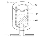
- the heat retention device may be applied to a hot water tank 501 that stores hot water W1.
- the hot water W1 stored in the hot water tank 501 corresponds to the heat source.
- the heat retention device may be applied to a catalyst device 503 supporting a catalyst 502.
- the catalyst device 503 is disposed in an exhaust pipe 504 through which exhaust gas from an internal combustion engine (not shown) flows.
- the catalyst 502 corresponds to a heat source.
- the enclosing portion 68 is arranged between the side surface 63a of the end plate 63 and the case 61 , but the arrangement of the enclosing portion 68 is not limited to this.
- the sealing section 68 may be arranged around the battery module 50.
- the sealed portion 68 in which a gas containing a rare gas is sealed is employed as the heat conduction suppressing portion, but the heat conduction suppressing portion is not limited to this.
- part or all of the enclosing portion 68 may be changed to a vacuum heat insulating material. Thereby, heat insulation performance (that is, heat conduction suppression performance) can be improved.
- a vacuum heat insulating material is provided in the gap, and the sealing portion 68 is provided in another wide gap. Is also good. That is, a vacuum heat insulating material is provided between the left and right side surfaces of the battery module 50 and the case 61 and between the lower surface of the battery module 50 and the case 61, and sealed between the upper surface of the battery module 50 and the case 61. A portion 68 may be provided. According to this, the manufacturing cost can be reduced as compared with the case where the vacuum heat insulating material is provided in all the gaps between the battery module 50 and the case 61.
- the heat source is not limited to these.
- an inverter, a motor, an ECU, or the like which is a device that generates heat by electric energy, may be employed as the heat source.
Abstract
保温装置は、熱源体(50、51)と、ケース(61)と、放熱量低減部(67、68)と、を備える。ケースは、熱源体との間に空間が形成されるように熱源体を固定し収容する。放熱量低減部は、熱源体から空間を介してケースに放出される熱量を低減する。これによれば、放熱量低減部を設けることで、熱源体から空間を介してケースに放出される熱量が低減される。このため、熱源体の断熱性を高めることができるので、熱源体の保温性を向上させることができる。
Description
本出願は、2018年7月26日に出願された日本特許出願2018-140227号に基づくもので、ここにその記載内容を援用する。
本開示は、熱源体を保温する保温装置に関する。
従来、特許文献1には、冬季のバッテリの冷却を防止するバッテリ用保温材が記載されている。特許文献1では、蓄熱性粒子を分散させた基材を、バッテリを包み込むような形状に成形して用いている。
しかしながら、上記特許文献1のバッテリ用保温材では、蓄熱性粒子を分散させた基材から熱が外部に逃げてしまうため、バッテリの保温性が悪くなる可能性がある。
本開示は上記点に鑑みて、熱源体の保温性を向上させることを目的とする。
上記目的を達成するため、本開示の一態様の保温装置は、熱源体と、ケースと、放熱量低減部と、を備える。ケースは、熱源体との間に空間が形成されるように熱源体を固定し収容する。放熱量低減部は、熱源体から空間を介してケースに放出される熱量を低減する。
これによれば、放熱量低減部を設けることで、熱源体から空間を介してケースに放出される熱量が低減される。このため、熱源体の断熱性を高めることができるので、熱源体の保温性を向上させることができる。
以下に、図面を参照しながら本開示を実施するための複数の形態を説明する。各実施形態において先行する実施形態で説明した事項に対応する部分には同一の参照符号を付して重複する説明を省略する場合がある。各実施形態において構成の一部のみを説明している場合は、構成の他の部分については先行して説明した他の実施形態を適用することができる。各実施形態で具体的に組合せが可能であることを明示している部分同士の組合せばかりではなく、特に組合せに支障が生じなければ、明示してなくとも実施形態同士を部分的に組み合せることも可能である。
(第1実施形態)
以下、本開示の保温装置を適用した最も好適な実施形態について図面に基づいて説明する。本実施形態は、車両用電池温調装置に搭載される電池パックに、本開示を適用したものである。
以下、本開示の保温装置を適用した最も好適な実施形態について図面に基づいて説明する。本実施形態は、車両用電池温調装置に搭載される電池パックに、本開示を適用したものである。
図1に示す車両用電池温調装置1は、車両に搭載された電池41、42を適切な温度に調整する電池温調装置である。車両用電池温調装置1は、車室内空間を適切な温度に調整する空調装置でもある。本実施形態では、車両用電池温調装置1は、走行用電動モータから車両走行用の駆動力を得る電気自動車に搭載されている。なお、車両用電池温調装置1は、エンジン(換言すれば内燃機関)および走行用電動モータから車両走行用の駆動力を得るハイブリッド自動車に搭載されていてもよい。
本実施形態の電気自動車は、車両停車時に外部電源(換言すれば商用電源)から供給された電力を、車両に搭載された電池41、42に充電可能となっている。電池41、42としては、例えばリチウムイオン電池を用いることができる。
電池に蓄えられた電力は、走行用電動モータのみならず、車両用電池温調装置1を構成する電動式構成機器をはじめとする各種車載機器に供給される。
車両用電池温調装置1は、冷凍サイクル装置10を有している。冷凍サイクル装置10は、圧縮機11、凝縮器12、膨張弁13、空気冷却用蒸発器14、定圧弁15および冷却水冷却用蒸発器16を備える蒸気圧縮式冷凍機である。本実施形態の冷凍サイクル装置10では、冷媒としてフロン系冷媒を用いており、高圧側冷媒圧力が冷媒の臨界圧力を超えない亜臨界冷凍サイクルを構成している。
圧縮機11は、電池から供給される電力によって駆動される電動圧縮機であり、冷凍サイクル装置10の冷媒を吸入して圧縮して吐出する。
凝縮器12は、圧縮機11から吐出された高圧側冷媒と高温冷却水回路20の冷却水とを熱交換させることによって高圧側冷媒を凝縮させる高圧側熱交換器である。
高温冷却水回路20の冷却水は、熱媒体としての流体である。高温冷却水回路20の冷却水は高温熱媒体である。本実施形態では、高温冷却水回路20の冷却水として、少なくともエチレングリコール、ジメチルポリシロキサンもしくはナノ流体を含む液体、または不凍液体が用いられている。高温冷却水回路20は、高温の熱媒体が循環する高温熱媒体回路である。
膨張弁13は、凝縮器12から流出した液相冷媒を減圧膨張させる減圧部である。膨張弁13は、機械式の温度式膨張弁である。機械式膨張弁は、感温部を有し、ダイヤフラム等の機械的機構によって弁体を駆動する温度式膨張弁である。
空気冷却用蒸発器14は、膨張弁13から流出した冷媒と車室内へ送風される空気とを熱交換させて車室内へ送風される空気を冷却する冷媒空気熱交換器である。空気冷却用蒸発器14では、冷媒が車室内へ送風される空気から吸熱する。
定圧弁15は、空気冷却用蒸発器14の出口側における冷媒の圧力を所定値に維持する圧力調整部(換言すれば圧力調整用減圧部)である。
定圧弁15は、機械式の可変絞り機構で構成されている。具体的には、定圧弁15は、空気冷却用蒸発器14の出口側における冷媒の圧力が所定値を下回ると、冷媒通路の通路面積(すなわち絞り開度)を減少させる。定圧弁15は、空気冷却用蒸発器14の出口側における冷媒の圧力が所定値を超えると、冷媒通路の通路面積(すなわち絞り開度)を増加させる。
サイクルを循環する循環冷媒流量の変動が少ない場合等には、定圧弁15に代えて、オリフィス、キャピラリチューブ等からなる固定絞りを採用してもよい。
冷却水冷却用蒸発器16は、冷媒の流れにおいて、空気冷却用蒸発器14および定圧弁15と並列に配置されている。
冷却水冷却用蒸発器16は、膨張弁13を流出した低圧冷媒と低温冷却水回路30の冷却水とを熱交換させることによって低圧冷媒を蒸発させる低圧側熱交換器である。冷却水冷却用蒸発器16で蒸発した気相冷媒は圧縮機11に吸入されて圧縮される。
低温冷却水回路30の冷却水は、熱媒体としての流体である。低温冷却水回路30の冷却水は低温熱媒体である。本実施形態では、低温冷却水回路30の冷却水として、少なくともエチレングリコール、ジメチルポリシロキサンもしくはナノ流体を含む液体、または不凍液体が用いられている。低温冷却水回路30は、低温の熱媒体が循環する低温熱媒体回路である。
高温冷却水回路20は、高温側循環流路20aを有している。高温側循環流路20aは、高温側冷却水が循環する冷却水流路である。
高温側循環流路20aには、高温側ポンプ21、ヒータコア22、凝縮器12および高温側ラジエータ24が配置されている。
高温側ポンプ21は、冷却水を吸入して吐出する熱媒体ポンプである。高温側ポンプ21は電動式のポンプである。高温側ポンプ21は、高温冷却水回路20を循環する冷却水の流量を調整する高温側流量調整部である。
ヒータコア22は、高温冷却水回路20の冷却水と車室内へ送風される空気とを熱交換させて車室内へ送風される空気を加熱する空気加熱用熱交換器である。ヒータコア22では、冷却水が車室内へ送風される空気に放熱する。
空気冷却用蒸発器14およびヒータコア22は、図示しない空調ケーシングに収容されている。ヒータコア22は、空調ケーシング内の空気通路において、空気冷却用蒸発器14の空気流れ下流側に配置されている。空調ケーシングには内気および外気が切り替え導入されるようになっている。空調ケーシングに導入された内気および外気は、図示しない送風機によって空気冷却用蒸発器14およびヒータコア22に送風される。
空調ケーシング内の空気通路において空気冷却用蒸発器14とヒータコア22との間には、図示しないエアミックスドアが配置されている。エアミックスドアは、空気冷却用蒸発器14を通過した冷風のうちヒータコア22に流入する冷風と、ヒータコア22をバイパスして流れる冷風との風量割合を調整する。
エアミックスドアによって温度調整された空調風は、空調ケーシングに形成された図示しない吹出口から車室内へ吹き出される。
高温側ラジエータ24は、高温冷却水回路20の冷却水と外気とを熱交換させる高温熱媒体外気熱交換器である。
低温冷却水回路30は、低温側循環流路30aを有している。低温側循環流路30aは、低温側冷却水が循環する流路である。
低温側循環流路30aには、低温側ポンプ31、冷却水冷却用蒸発器16、低温側電気ヒータ32、インバータ33、モータジェネレータ34および低温側ラジエータ35が配置されている。
低温側ポンプ31は、冷却水を吸入して吐出する熱媒体ポンプである。低温側ポンプ31は電動式のポンプである。
低温側電気ヒータ32は、電力が供給されることによって発熱し、低温冷却水回路30の冷却水を加熱する補助加熱器である。
インバータ33は、第1電池41および第2電池42から供給された直流電力を交流電力に変換してモータジェネレータ34に出力する。第1電池41および第2電池42はそれぞれ、複数個の電池セルで構成されている組電池である。
モータジェネレータ34は、インバータ33から出力された電力を利用して走行用駆動力を発生するとともに、減速中や降坂中に回生電力を発生させる。インバータ33およびモータジェネレータ34は、低温冷却水回路30の冷却水によって、充分な性能を発揮できる適正な温度帯の範囲内に温度調整される。
低温側ラジエータ35は、低温冷却水回路30の冷却水と外気とを熱交換させる低温熱媒体外気熱交換器である。低温側ラジエータ35は、低温冷却水回路30の冷却水が熱交換する熱交換部である。
高温側ラジエータ24および低温側ラジエータ35には、図示しない室外送風機によって外気が送風される。
第1電池41は、低温側循環流路30aに配置されている。低温側循環流路30aを流れる冷却水によって第1電池41の温度が調整される。低温側循環流路30aは、第1電池41を冷却水によって温度調整する温度調整部である。低温側循環流路30aは、第1電池41を冷却水によって冷却する冷却部である。第2電池42は、低温側循環流路30aに配置されていない。
第1電池41は、複数の電池モジュール50を備えている。各電池モジュール50は、直方体状の電池セル(図示せず)を複数積層した積層体で構成されている。電池モジュール50は、充放電に伴い熱を発生させる熱源体である。
電池モジュール50の各電池セルは、充放電可能な二次電池(本実施形態ではリチウムイオン電池)である。この種の電池は、低温になると化学反応が進みにくく充放電に関して充分な性能を発揮することができない。一方、この種の電池は、高温になると劣化が進行しやすい。したがって、各電池セルの温度は、充分な性能を発揮できる適正な温度帯(例えば、10℃以上かつ40℃以下)の範囲内に温度調整されている必要がある。
電池モジュール50は、ケース61に収容されて電池パック60を構成している。本実施形態では、1つのケース61内に1つの電池モジュール50が収容されている。以下、本実施形態における電池パック60を図2に基づいて説明する。
なお、以下の各図における上下、左右、前後を示す矢印は、実施形態における各構成の位置関係の理解を容易にするために、三次元空間の直交座標系(例えば、X軸、Y軸、Z軸)に対応する基準として例示したものである。したがって、本開示に係る電池パック60および電池モジュール50の姿勢等は、各図に示す状態に限定されるものではなく、適宜変更可能である。
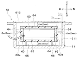
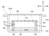
図2に示すように、ケース61は、電池モジュール50との間に空間が形成されるように電池モジュール50を固定し収容する収容部である。ケース61の具体的材質としては、樹脂、アルミニウム、ステンレス、鉄、銅等が用いられる。また、輻射を考慮すると、ケース61の材質としては、アルミニウムメッキを施した樹脂が最も好適である。
ケース61は、本体部611および蓋部材612を組み合わせることにより構成されている。本体部611は、上方側に開口部を有する箱状に形成されている。蓋部材612は、本体部611の開口部を閉塞するように形成されている。
電池モジュール50の外側には、冷却器62が設けられている。本実施形態では、冷却器62は、電池モジュール50の下方側に設けられている。冷却器62は、低温側循環流路30aを循環する冷却水が流れるように構成されている。冷却器62は、冷却水により電池モジュール50(すなわち第1電池41)を冷却する冷却部である。
電池モジュール50および冷却器62の左右面には、それぞれ、電池モジュール50および冷却器62を保持する平板状のエンドプレート63が設けられている。
電池モジュール50の外側には、蓄熱材64が設けられている。より詳細には、電池モジュール50の上面および前後面、冷却器62の下面、およびエンドプレート63の外面(すなわち、電池モジュール50および冷却器62と反対側の面)には、蓄熱材64が設けられている。
電池モジュール50の各面(すなわち、上下面、左右面および前後面)は、蓄熱材64に覆われている。換言すると、電池モジュール50の全面は、蓄熱材64に覆われている。
蓄熱材64は、相変化に伴う潜熱の出入りを利用して蓄熱または放熱を行う潜熱蓄熱材である。本実施形態では、蓄熱材64として、マイクロカプセル潜熱蓄熱材を含有した樹脂蓄熱材を用いている。なお、マイクロカプセル潜熱蓄熱材は、潜熱蓄熱材がマイクロカプセル内に封入された蓄熱材である。
潜熱蓄熱材としては、潜熱の出入り温度が0℃以下の潜熱蓄熱材を採用することができる。具体的には、潜熱蓄熱材として、例えば、パラフィン系炭化水素、水和物系、金属系、水系の潜熱蓄熱材を採用することができる。
ところで、電池モジュール50の各面とケース61との間には、空間が形成されている。具体的には、電池モジュール50の全面を覆っている蓄熱材64の表面とケース61の内壁面との間には、空間が形成されている。この空間には、気体としての空気が存在している。なお、この空間の一部に、断熱材が設けられてもよい。
電池モジュール50の各面とケース61との間の最大距離は、電池モジュール50の表面における空気の対流が抑制される所定の距離以下となるように設定されている。換言すると、電池モジュール50の各面と、ケース61における電池モジュール50の各面に対向する内壁面との間の最大距離は、それぞれ、電池モジュール50の表面における空気の対流が抑制される所定の距離以下となるように設定されている。
以下、電池モジュール50の表面における空気の対流が抑制される所定の距離を、対流抑制距離という。
本実施形態では、電池モジュール50の全面が蓄熱材64に覆われている。このため、電池モジュール50の各面を覆っている各蓄熱材64の表面と、ケース61のうち蓄熱材64の表面に対向する内壁面との間の最大距離Dmが、対流抑制距離以下となるように設定されている。
ここで、空気層における厚さと熱抵抗との関係を図3に示す。図3に示すように、密閉されていない一般室内では、空気層の厚さが2cm以上の場合、空気層の熱抵抗はほぼ一定となる。このため、上述の対流抑制距離として、例えば1.5cmを採用することができる。
したがって、電池モジュール50の各面と、ケース61における電池モジュール50の各面に対向する内壁面との間の最大距離は、それぞれ、1.5cm以下に設定されている。本実施形態では、電池モジュール50の各面を覆っている各蓄熱材64の表面と、ケース61における各蓄熱材64の表面に対向する内壁面との間の最大距離Dmが、それぞれ、1.5cm以下に設定されている。
以下、電池モジュール50の上面を覆う蓄熱材64の表面と、ケース61における蓄熱材64の表面と対向する内壁面との最大距離Dmを、上方最大距離Dmaという。冷却器62の下面を覆う蓄熱材64の表面と、ケース61における蓄熱材64の表面と対向する内壁面との最大距離Dmを、下方最大距離Dmbという。
また、エンドプレート63における、電池モジュール50との接合面と反対側の面を側面63aという。そして、エンドプレート63の側面63aから、ケース61における側面63aに対向する面との最大距離Dmを、側方最大距離Dmcという。
本実施形態では、上方最大距離Dma、下方最大距離Dmbおよび側方最大距離Dmcは、互いに同じ長さに設定されている。
図2に戻り、ケース61内には、蓄熱材64に覆われた電池モジュール50をケース61の下方側の内壁面から間隔を空けた状態で固定するための接続部65が設けられている。本実施形態の接続部65は、ケース61の下方側の内壁面から電池モジュール50側に向かって延びる棒状に形成されている。
ここで、蓄熱材64の厚み寸法をttsという。また、蓄熱材64と、蓄熱材64に対向するケース61との隙間寸法をtairという。本実施形態では、蓄熱材64の厚み寸法ttsを、蓄熱材64とケース61との隙間寸法tairの1/3以下としている。また、蓄熱材64の厚み寸法ttsを1mmとしてもよい。
図4に示すように、第1電池41からインバータ33およびモータジェネレータ34への電力の供給は、第1スイッチ47aによって断続されるようになっている。第2電池42からインバータ33およびモータジェネレータ34への電力の供給は、第2スイッチ48aによって断続されるようになっている。第1スイッチ47aおよび第2スイッチ48aの切り替えにより、第1電池41および第2電池42を任意に放電させることができる。
第2電池42の各電池セルの電池容量は、第1電池41の各電池セルの電池容量よりも小さくなっている。第2電池42の各電池セルの個数は、第1電池41の各電池セルの個数と同じになっている。したがって、第2電池42の電池容量は、第1電池41の電池容量よりも小さくなっている。
第1電池41、第2電池42、インバータ33およびモータジェネレータ34を有する電気回路70には、DCインレット71、充電器72およびDCDCコンバータ73等が設けられている。
DCインレット71は、DC充電スタンド74で第1電池41、第2電池42を充電する際に、DC充電スタンド74のプラグに接続される。充電器72のプラグは、家庭用電力で第1電池41、第2電池42を充電する際に、家庭用コンセント75に接続される。DCDCコンバータ73は、第1電池41および第2電池42から供給される電力の電圧を12Vに変換して、車両に搭載された補機76に供給する。
図5は、車両停止後の経過時間と電池平均温度との関係を示すグラフである。比較例では、電池に蓄熱材が設けられておらず、電池モジュール50の各面とケース61との間に空間が形成されていない。本実施形態では、比較例と比較して、経過時間に対する温度低下量を小さく抑えることができる。
図6は、本実施形態と比較例とで、電池の暖機に必要な熱量を比較したグラフである。本実施形態では、比較例と比較して、電池の暖機に必要な熱量を小さく抑えることができる。
図7は、リチウムイオン電池における電池温度と電池出力および内部抵抗との関係を示すグラフである。リチウムイオン電池の特性として、低温域では小容量電池にて高出力が得られ、中間温度域では大容量電池にて高出力が得られる。高温域では電池の寿命が低下してしまう。
本実施形態では、このようなリチウムイオン電池の特性に鑑みて、環境温度、電池温度および電池残量に応じた電池作動を行うので、小容量電池を無駄なく年中使用可能となる。
以上説明したように、本実施形態では、電池モジュール50の各面とケース61との間に空間を形成する。そして、電池モジュール50の各面とケース61との間に形成された空間に、気体として空気を存在させている。
さらに、電池モジュール50の各面とケース61との間の最大距離Dmを、対流抑制距離以下となるように設定している。具体的には、電池モジュール50の各面を覆っている蓄熱材64の表面と、ケース61における蓄熱材64の表面と対向する内壁面との間の最大距離Dmを、対流抑制距離(例えば1.5cm)以下となるように設定している。
これにより、電池モジュール50の各面とケース61との間に形成された空間によって、電池モジュール50の表面における空気の対流を抑制し、電池モジュール50から空間を介してケース61に放出される熱量を低減することができる。このため、熱源体である電池モジュール50の断熱性を高めることができるので、電池モジュール50の保温性を向上させることが可能となる。
したがって、本実施形態における電池モジュール50の各面とケース61との間に形成された空間が、対流抑制部および放熱量低減部を構成している。そして、当該空間を形成する空間形成部であるケース61は、対流抑制部および放熱量低減部を形成する部材である。
上述したように、本実施形態では、電池モジュール50の外側に、蓄熱材64を設けている。これによれば、電池モジュール50で発生した熱を蓄熱材64に蓄えることができる。そして、外気温(すなわち環境温度)が低下した際には、電池モジュール50に対して蓄熱材64に蓄えた熱を放出することにより、電池モジュール50の温度低下を抑制することができる。これにより、電池モジュール50の保温性を向上させることができる。
さらに、本実施形態では、蓄熱材64として潜熱蓄熱材を用いている。これによれば、環境温度が潜熱蓄熱材の融点より高い場合、蓄熱材64において蓄熱は行われないため、夏季等の高外気温時においても本実施形態の電池パック60をそのまま使用することが可能となる。
(第2実施形態)
次に、本開示の第2実施形態について図8に基づいて説明する。本第2実施形態では、上記第1実施形態に対して、電池モジュール50周辺の構成を変更している。具体的には、蓄熱材64および接続部65を廃止して、電池モジュール50をケース61の下方面に配置している。
次に、本開示の第2実施形態について図8に基づいて説明する。本第2実施形態では、上記第1実施形態に対して、電池モジュール50周辺の構成を変更している。具体的には、蓄熱材64および接続部65を廃止して、電池モジュール50をケース61の下方面に配置している。
図8に示すように、エンドプレート63の下端部は、冷却器62の下端面より下方側に突出している。エンドプレート63の下端部は、ケース61の下方側の内壁面に接続されている。そして、冷却器62の下面とケース61との間には、空間が形成されている。
本実施形態において、電池モジュール50の上面と、ケース61における電池モジュール50の上面に対向する内壁面との最大距離を、上方最大距離Dmaという。冷却器62の下面と、ケース61における冷却器62の下面に対向する内壁面との最大距離を、下方最大距離Dmbという。エンドプレート63の側面63aから、ケース61におけるエンドプレート63の側面63aに対向する面との最大距離を、側方最大距離Dmcという。
上方最大距離Dma、下方最大距離Dmb、側方最大距離Dmcは、それぞれ、対流抑制距離以下となるように設定されている。さらに、本実施形態では、上方最大距離Dmaは側方最大距離Dmcより長く、かつ、下方最大距離Dmbは側方最大距離Dmcより短く設定されている。
その他の電池パック60の構成は、第1実施形態と同様である。したがって、本実施形態の電池パック60においても、第1実施形態と同様の効果を得ることができる。
(第3実施形態)
次に、本開示の第3実施形態について図9および図10に基づいて説明する。本第3実施形態では、上記第1実施形態に対して、電池モジュール50の構成を変更している。具体的には、電池モジュール50の外側を覆う蓄熱材64を廃止して、電池モジュール50の構成部材の一部である絶縁板53を蓄熱材で構成している。
次に、本開示の第3実施形態について図9および図10に基づいて説明する。本第3実施形態では、上記第1実施形態に対して、電池モジュール50の構成を変更している。具体的には、電池モジュール50の外側を覆う蓄熱材64を廃止して、電池モジュール50の構成部材の一部である絶縁板53を蓄熱材で構成している。
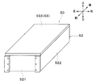
図9および図10に示すように、電池モジュール50は、電池セル51、枠体52および絶縁板53等を備えている。
電池セル51は、充放電に伴い熱を発生させる熱源体である。電池セル51は、前後方向に複数積層されて積層体510を構成している。
枠体52は、金属により構成されている。枠体52は、電池セル51の積層体510における左右面および前後面を覆うような四角筒状に形成されている。枠体52の上面および下面には、開口部(図示せず)が形成されている。
より詳細には、枠体52は、2つの第1金属部材521、および2つの第2金属部材522を組み合わせて形成されている。
第1金属部材521は、長方形状の板状部材である。第1金属部材521は、電池セル51の積層体510における前面および後面を覆うように形成されている。
第2金属部材522は、上下方向に垂直な断面がコの字状(換言すると、バスタブ状)に形成されている。第2金属部材522は、電池セル51の積層体510を左側面および右側面から覆うように形成されている。
第1金属部材521および第2金属部材522は、ネジ等の締結部材で一体に結合されている。
絶縁板53は、電池セル51の積層体510とケース61との間に設けられた絶縁部材である。本実施形態では、絶縁板53は、マイクロカプセル蓄熱材を含有した樹脂蓄熱材で構成されている。このため、絶縁板53は、少なくとも一部に蓄熱材を有している。つまり、絶縁板53は、蓄熱機能を有している。
マイクロカプセル蓄熱材としては、上記第1実施形態と同様のマイクロカプセル潜熱蓄熱材を採用することができる。
より詳細には、絶縁板53は、長方形の板状に形成されている。絶縁板53は、電池セル51の積層体510における各面(すなわち、上下面、左右面および前後面)を覆うように1枚ずつ配置されている。
本実施形態では、絶縁板53として、2枚の第1絶縁板531、2枚の第2絶縁板532、および2枚の第3絶縁板533が設けられている。第1絶縁板531は、電池セル51の積層体510における前面および後面をそれぞれ覆うように配置されている。第2絶縁板532は、電池セル51の積層体510における左面および右面をそれぞれ覆うように配置されている。第3絶縁板533は、電池セル51の積層体510における上面および下面をそれぞれ覆うように配置されている。
第1絶縁板531および第2絶縁板532は、枠体52の内側に配置されている。すなわち、第1絶縁板531および第2絶縁板532は、電池セル51の積層体510と枠体52との間に配置されている。これにより、電池セル51と枠体52との間が絶縁されている。
第3絶縁板533は、枠体52の上面および下面に形成された開口部を塞ぐように配置されている。
上述したように、本実施形態では、電池モジュール50の構成部材の一部である絶縁板53を蓄熱材で構成している。これによれば、電池モジュール50の外側に蓄熱材を別途設ける必要がないため、部品点数の増加を招くことがない。したがって、製造コストを低減しつつ、電池モジュール50の保温性を向上させることができる。
(第4実施形態)
次に、本開示の第4実施形態について図11に基づいて説明する。本第4実施形態では、上記第1実施形態に対して、電池モジュール50周辺の構成を変更している。具体的には、電池モジュール50の下方側の蓄熱材64および接続部65を廃止して、電池モジュール50をケース61の下方面に配置している。
次に、本開示の第4実施形態について図11に基づいて説明する。本第4実施形態では、上記第1実施形態に対して、電池モジュール50周辺の構成を変更している。具体的には、電池モジュール50の下方側の蓄熱材64および接続部65を廃止して、電池モジュール50をケース61の下方面に配置している。
図8に示すように、エンドプレート63の下端部は、冷却器62の下端面より下方側に突出している。エンドプレート63の下端部は、ケース61の下方側の内壁面に接続されている。そして、冷却器62の下面とケース61との間には、空間が形成されている。
本実施形態において、冷却器62の下面と、ケース61における冷却器62の下面に対向する内壁面との最大距離を、下方最大距離Dmbという。そして、上方最大距離Dma、下方最大距離Dmb、側方最大距離Dmcは、それぞれ、対流抑制距離以下となるように設定されている。さらに、本実施形態では、上方最大距離Dmaおよび側方最大距離Dmcは互いに同じ長さ、かつ、下方最大距離Dmbは上方最大距離Dmaおよび側方最大距離Dmcより短く設定されている。
その他の電池パック60の構成は、第1実施形態と同様である。したがって、本実施形態の電池パック60においても、第1実施形態と同様の効果を得ることができる。
(第5実施形態)
次に、本開示の第5実施形態について図12に基づいて説明する。本第5実施形態では、上記第1実施形態に対して、ケース61内の構成を変更している。
次に、本開示の第5実施形態について図12に基づいて説明する。本第5実施形態では、上記第1実施形態に対して、ケース61内の構成を変更している。
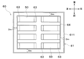
図12に示すように、本実施形態では、ケース61内に、複数(本例では8個)の電池モジュール50が収容されている。複数の電池モジュール50の全てを覆うように、蓄熱材64が配置されている。また、蓄熱材64の各面と、ケース61における蓄熱材64の各面に対向する内壁面との最大距離Dmは、それぞれ、対流抑制距離以下となるように設定されている。
その他の電池パック60の構成は、第1実施形態と同様である。したがって、本実施形態の電池パック60においても、第1実施形態と同様の効果を得ることができる。
また、上述のように、本実施形態では、1つのケース61において、複数の電池モジュール50の全てを覆うように蓄熱材64を配置している。このため、各電池モジュール50を1つずつ覆うように蓄熱材64を配置する場合と比較して、蓄熱材64の点数を削減することができる。したがって、部品点数の増加を抑制しつつ、複数の電池モジュール50の保温性を向上させることができる。
(第6実施形態)
次に、本開示の第6実施形態について図13に基づいて説明する。本第6実施形態では、上記第5実施形態に対して、蓄熱材64の配置を変更している。
次に、本開示の第6実施形態について図13に基づいて説明する。本第6実施形態では、上記第5実施形態に対して、蓄熱材64の配置を変更している。
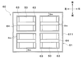
図13に示すように、本実施形態では、複数(本例では2つ)の電池モジュール50を一組として、一組の電池モジュール50をまとめて覆うように蓄熱材64が配置されている。このため、ケース61内には、蓄熱材64で覆われた一組の電池モジュール50が、複数組(本例では4組)配置されている。すなわち、ケース内61には、一組の電池モジュール50を覆うように構成された蓄熱材64が複数配置されている。
複数配置された蓄熱材64のうち、ケース61と対向する各面と、ケース61の内壁面との最大距離Dmは、それぞれ、対流抑制距離以下となるように設定されている。
その他の電池パック60の構成は、第5実施形態と同様である。したがって、本実施形態の電池パック60においても、第5実施形態と同様の効果を得ることができる。
(第7実施形態)
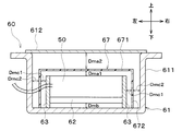
次に、本開示の第7実施形態について図14に基づいて説明する。本第7実施形態では、上記第2実施形態に対して、ケース61内の構成を変更している。具体的には、ケース61内に板状部材67を配置している。
次に、本開示の第7実施形態について図14に基づいて説明する。本第7実施形態では、上記第2実施形態に対して、ケース61内の構成を変更している。具体的には、ケース61内に板状部材67を配置している。
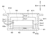
図14に示すように、ケース61内の空間には、少なくとも電池モジュール50の表面と対向する板状部材67が設けられている。板状部材67は、電池モジュール50の表面を覆うように配置されている。板状部材67は、電池モジュール50と接触しないように、電池モジュール50との間に間隔を空けて配置されている。
板状部材67は、金属(本例ではアルミニウム)により構成されている。本実施形態では、板状部材67は、ケース61の一部と一体に形成されている。
具体的には、板状部材67は、電池モジュール50の上方の表面と対向する上面部671と、エンドプレート63の側面63aと対向する側面部672とを有している。
本実施形態において、電池モジュール50の上方の表面と板状部材67の上面部671との最大距離を、上方第1最大距離Dma1という。板状部材67の上面部671とケース61の蓋部材612との最大距離を、上方第2最大距離Dma2という。
エンドプレート63の側面63aと板状部材67の側面部672との最大距離を、第1側方最大距離Dmc1という。板状部材67の側面部672と、側面部672に対向するケース61の内壁面との最大距離を第2側方最大距離Dmc2という。
上方第1最大距離Dma1、下方最大距離Dmb、第1側方最大距離Dmc1は、それぞれ、対流抑制距離以下となるように設定されている。さらに、本実施形態では、上方第1最大距離Dma1は第1側方最大距離Dmc1より長く、かつ、下方最大距離Dmbは第1側方最大距離Dmc1より短く設定されている。
上方第1最大距離Dma1および上方第2最大距離Dma2は、互いに同じ長さに設定されている。第1側方最大距離Dmc1および第2側方最大距離Dmc2は、互いに同じ長さに設定されている。
上述のように、本実施形態では、ケース61内の空間に、少なくとも電池モジュール50の表面と対向する板状部材67を設けている。これによれば、板状部材67によって、電池モジュール50の表面における空気の対流を抑制することができる。したがって、本実施形態の板状部材67は、対流抑制部に相当している。
さらに、ケース61内の空間に板状部材67を設けることにより、電池モジュール50からの熱輻射を遮蔽することができる。すなわち、板状部材67により、電池モジュール50からの熱輻射を抑制することができる。したがって、本実施形態の板状部材67は、遮蔽板および熱輻射抑制部に相当している。
このように、板状部材67により、電池モジュール50の表面における空気の対流を抑制しつつ、電池モジュール50からの熱輻射を抑制することで、電池モジュール50から空間を介してケース61に放出される熱量を確実に低減することができる。これにより、電池モジュール50の断熱性をより高めることができるので、電池モジュール50の保温性をより向上させることが可能となる。したがって、本実施形態の板状部材67は、放熱量低減部に相当している。
さらに、本実施形態では、ケース61内の空間に板状部材67を設けることにより、電池モジュール50とケース61との隙間を、板状部材67により分断している。これにより、電池モジュール50とケース61との隙間が大きい電池パック60においても、電池モジュール50の表面と、電池モジュール50の表面に対向する板状部材67との最大距離を対流抑制距離以下となるように設定することが可能となる。
なお、電池モジュール50の表面と、電池モジュール50の表面に対向する板状部材67との最大距離を、0mmとしてもよい。すなわち、電池モジュール50と板状部材67とが密着していてもよい。
一方、板状部材67と、ケース61のうち板状部材67に対向する内壁面との距離は、0mmより大きく、対流抑制距離(本例では1.5cm)以下に設定されている。すなわち、板状部材67とケース61とは密着していない。
(第8実施形態)
次に、本開示の第8実施形態について図15に基づいて説明する。本第8実施形態では、上記第7実施形態に対して、板状部材67の材質を変更している。
次に、本開示の第8実施形態について図15に基づいて説明する。本第8実施形態では、上記第7実施形態に対して、板状部材67の材質を変更している。
図14に示すように、本実施形態の板状部材67は、マイクロカプセル蓄熱材を含有した樹脂蓄熱材で構成されている。このため、板状部材67は、蓄熱機能を有している。マイクロカプセル蓄熱材としては、上記第1実施形態と同様のマイクロカプセル潜熱蓄熱材を採用することができる。
本実施形態では、電池モジュール50の各面と板状部材67との間の最大距離が、板状部材67とケース61との間の最大距離よりも短く設定されている。すなわち、上方第1最大距離Dma1は、上方第2最大距離Dma2より短く設定されている。また、第1側方最大距離Dmc1は、第2側方最大距離Dmc2より短く設定されている。
これによれば、蓄熱機能を有する板状部材67と電池モジュール50との距離が短くなるので、電池モジュール50で発生した熱が板状部材67に蓄熱しやすくなる。このため、電池パック60における蓄熱性を向上させて、電池モジュール50の保温性を向上させることができる。
さらに、本実施形態では、上方第1最大距離Dma1、下方最大距離Dmbおよび第1側方最大距離Dmc1は、互いに同じ長さに設定されている。また、上方第2最大距離Dma2は第2側方最大距離Dmc2より長く、かつ、下方最大距離Dmbは第2側方最大距離Dmc2より短く設定されている。
その他の電池パック60の構成は、第7実施形態と同様である。したがって、本実施形態の電池パック60においても、第7実施形態と同様の効果を得ることができる。
(第9実施形態)
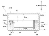
次に、本開示の第9実施形態について図16に基づいて説明する。本第9実施形態では、上記第2実施形態に対して、ケース61内の構成を変更している。具体的には、ケース61内に封入部68を配置している。
次に、本開示の第9実施形態について図16に基づいて説明する。本第9実施形態では、上記第2実施形態に対して、ケース61内の構成を変更している。具体的には、ケース61内に封入部68を配置している。
図16に示すように、ケース61内には、希ガスであるアルゴンガスを含む気体が封入された封入部68が設けられている。封入部68に封入された気体中のアルゴンガスの濃度は、空気中のアルゴンガスの濃度よりも高い。本実施形態では、封入部68は、エンドプレート63の側面63aとケース61との間に配置されている。
上述のように、ケース61内に、希ガスであるアルゴンガスを含む気体が封入された封入部68を設けることで、電池モジュール50からケース61への熱伝導を抑制することができる。これにより、電池モジュール50から空間を介してケース61に放出される熱量を低減することができるので、電池モジュール50の断熱性を高めて、電池モジュール50の保温性を向上させることが可能となる。したがって、本実施形態の封入部68は、熱伝導抑制部および放熱量低減部に相当している。
ここで、本実施形態の封入部68に代えて真空断熱材を用いた断熱構造を比較例の断熱構造という。本実施形態では、比較例の断熱構造と比較して、製造コストを低減することができる。
本開示は上述の実施形態に限定されることなく、本開示の趣旨を逸脱しない範囲内で、例えば以下のように種々変形可能である。また、上記各実施形態に開示された手段は、実施可能な範囲で適宜組み合わせてもよい。
(1)上記第3実施形態では、絶縁板53を、マイクロカプセル蓄熱材を含有した樹脂蓄熱材で構成した例について説明した。同様に、上記第8実施形態では、板状部材67を、マイクロカプセル蓄熱材を含有した樹脂蓄熱材で構成した例について説明した。
しかしながら、絶縁板53および板状部材67の材質は、樹脂蓄熱材に限定されない。例えば、絶縁板53および板状部材67を、ゴム蓄熱材(換言すると蓄熱性ゴム材料)で構成してもよい。
(2)上記第7実施形態では、板状部材67を金属により構成した例について説明したが、板状部材67の材質はこれに限定されない。例えば、板状部材67を、樹脂により構成してもよい。
(3)上記第9実施形態では、封入部68に封入される希ガスとして、アルゴンガスを採用した例について説明したが、希ガスはこれに限定されない。例えば、封入部68に封入される希ガスとして、ネオンガス、クリプトンガス、キセノンガスを採用してもよい。なお、封入部68における電池モジュール50からケース61への熱伝導抑制性能は、ネオンガス、アルゴンガス、クリプトンガス、キセノンガスの順に高くなる。
(4)上記実施形態では、電池モジュール50の下方側に、冷却器62を設けた例について説明したが、電池モジュール50の下方側の構成はこれに限定されない。例えば、電池モジュール50の下方に、電池モジュール50を加熱するヒータを設けてもよいし、冷却器62およびヒータの双方を設けてもよい。また、冷却器62を廃止してもよい。
(5)上記実施形態では、本開示に係る保温装置を、車両用電池温調装置1に搭載される電池パック60に適用した例について説明したが、保温装置の適用はこれに限定されない。
例えば、図17に示すように、本開示に係る保温装置を、温水W1を貯留する温水タンク501に適用してもよい。この場合、温水タンク501に貯留される温水W1が、熱源体に相当している。
また、図18に示すように、本開示に係る保温装置を、触媒502が担持された触媒装置503に適用してもよい。具体的には、触媒装置503は、内燃機関(図示せず)の排気が流通する排気配管504に配置されている。この場合、触媒502が、熱源体に相当している。
(6)上記第9実施形態では、封入部68を、エンドプレート63の側面63aとケース61との間に配置した例について説明したが、封入部68の配置はこれに限定されない。例えば、封入部68を、電池モジュール50の周囲に配置してもよい。
(7)上記第9実施形態では、熱伝導抑制部として、希ガスを含む気体が封入された封入部68を採用した例について説明したが、熱伝導抑制部はこれに限定されない。例えば、封入部68の一部または全部を、真空断熱材に変更してもよい。これにより、断熱性能(すなわち熱伝導抑制性能)を向上させることができる。
また、上記第9実施形態の封入部68と真空断熱材とを併用することで、製造コストを低減しつつ、断熱性能を向上させることができる。
例えば、電池モジュール50の左右方向側面および下方面において、ケース61との間の隙間を十分に確保することができない場合、隙間に真空断熱材を設け、他の広い隙間に封入部68を設けてもよい。すなわち、電池モジュール50の左右方向側面とケース61との間、および電池モジュール50の下方面とケース61との間に真空断熱材を設け、電池モジュール50の上方面とケース61との間に封入部68を設けてもよい。これによれば、電池モジュール50とケース61との隙間の全てに真空断熱材を設けた場合と比較して、製造コストを低減することができる。
(8)上記実施形態では、熱源体として、電池モジュール50または電池セル51を採用した例について説明したが、熱源体はこれらに限定されない。例えば、熱源体として、電気エネルギによって発熱する機器であるインバータ、モータ、ECU等を採用してもよい。
本開示は、実施例に準拠して記述されたが、本開示は当該実施例や構造に限定されるものではないと理解される。本開示は、様々な変形例や均等範囲内の変形をも包含する。加えて、様々な組み合わせや形態、さらには、それらに一要素のみ、それ以上、あるいはそれ以下、を含む他の組み合わせや形態をも、本開示の範疇や思想範囲に入るものである。
Claims (15)
- 熱源体(50、51)と、
前記熱源体との間に空間が形成されるように前記熱源体を固定し収容するケース(61)と、
前記熱源体から前記空間を介して前記ケースに放出される熱量を低減する放熱量低減部(67、68)と、を備える保温装置。 - 前記熱源体(50)の外側には、相変化に伴う潜熱の出入りを利用して蓄熱または放熱を行う潜熱蓄熱材(64)が設けられている請求項1に記載の保温装置。
- 前記熱源体(51)と前記ケースとの間には、絶縁部材(53)が設けられており、
前記絶縁部材は、少なくとも一部に蓄熱材を有している請求項1に記載の保温装置。 - 前記空間には、気体が存在しており、
前記放熱量低減部は、前記熱源体の表面における前記気体の対流を抑制する対流抑制部(67)を含む請求項1ないし3のいずれか1つに記載の保温装置。 - 前記熱源体の各面と前記ケースとの間に、空間が形成されており、
前記熱源体の各面と前記ケースとの間の最大距離は、前記熱源体の表面における前記気体の対流が抑制される所定の距離以下となるように設定されている請求項4に記載の保温装置。 - 前記空間には、少なくとも前記熱源体の表面と対向する板状部材(67)が設けられており、
前記対流抑制部は、前記板状部材を含む請求項4に記載の保温装置。 - 前記板状部材は、蓄熱機能を有している請求項6に記載の保温装置。
- 前記板状部材は、少なくとも一部に、相変化に伴う潜熱の出入りを利用して蓄熱または放熱を行う潜熱蓄熱材を有しており、
前記潜熱の出入り温度が0℃以下である請求項7に記載の保温装置。 - 前記板状部材は、前記熱源体の各面と前記板状部材との間の最大距離(Dm)が前記熱源体の表面における前記気体の対流が抑制される所定の距離以下となるように設けられている請求項6ないし8のいずれか1つに記載の保温装置。
- 前記熱源体の各面と前記板状部材との間の最大距離(Dma1、Dmc1)が、前記板状部材と前記ケースとの間の最大距離(Dma2、Dmc2)よりも短い請求項7または8に記載の保温装置。
- 前記放熱量低減部は、前記空間における熱の輻射を抑制する熱輻射抑制部(67)を含む請求項1ないし10のいずれか1つに記載の保温装置。
- 前記熱源体と前記ケースとの間には、前記熱源体からの熱輻射を遮蔽する遮蔽板(67)が設けられており、
前記熱輻射抑制部は、前記遮蔽板を含む請求項11に記載の保温装置。 - 前記放熱量低減部は、前記熱源体から前記ケースへの熱伝導を抑制する熱伝導抑制部(68)を含む請求項1ないし12のいずれか1つに記載の保温装置。
- 前記空間には、希ガスを含む気体が封入された封入部(68)が設けられており、
前記封入部に封入された前記気体中の前記希ガスの濃度は、空気中の前記希ガスの濃度よりも高く、
前記熱伝導抑制部は、前記封入部を含む請求項13に記載の保温装置。 - 前記熱源体の外側には、前記熱源体を冷却する冷却部(62)が設けられている請求項1ないし14のいずれか1つに記載の保温装置。
Applications Claiming Priority (2)
| Application Number | Priority Date | Filing Date | Title |
|---|---|---|---|
| JP2018-140227 | 2018-07-26 | ||
| JP2018140227A JP7070200B2 (ja) | 2018-07-26 | 2018-07-26 | 保温装置 |
Publications (1)
| Publication Number | Publication Date |
|---|---|
| WO2020022065A1 true WO2020022065A1 (ja) | 2020-01-30 |
Family
ID=69180983
Family Applications (1)
| Application Number | Title | Priority Date | Filing Date |
|---|---|---|---|
| PCT/JP2019/027362 WO2020022065A1 (ja) | 2018-07-26 | 2019-07-10 | 保温装置 |
Country Status (2)
| Country | Link |
|---|---|
| JP (1) | JP7070200B2 (ja) |
| WO (1) | WO2020022065A1 (ja) |
Cited By (2)
| Publication number | Priority date | Publication date | Assignee | Title |
|---|---|---|---|---|
| CN111540920A (zh) * | 2020-05-09 | 2020-08-14 | 中国工程物理研究院电子工程研究所 | 一种热电池真空全覆盖式保温结构及其应用 |
| CN113285146A (zh) * | 2021-07-22 | 2021-08-20 | 华东交通大学 | 一种电动汽车电池保温装置及方法 |
Citations (4)
| Publication number | Priority date | Publication date | Assignee | Title |
|---|---|---|---|---|
| JPS6273579A (ja) * | 1985-09-26 | 1987-04-04 | Kawasaki Heavy Ind Ltd | ナトリウム−イオウ電池 |
| JPH1032021A (ja) * | 1996-05-17 | 1998-02-03 | Daihatsu Motor Co Ltd | バッテリ保温カバー |
| JP2015002108A (ja) * | 2013-06-17 | 2015-01-05 | 住友電気工業株式会社 | 二次電池システム |
| JP2016105365A (ja) * | 2014-12-01 | 2016-06-09 | マツダ株式会社 | 自動車のバッテリー保護装置 |
-
2018
- 2018-07-26 JP JP2018140227A patent/JP7070200B2/ja active Active
-
2019
- 2019-07-10 WO PCT/JP2019/027362 patent/WO2020022065A1/ja active Application Filing
Patent Citations (4)
| Publication number | Priority date | Publication date | Assignee | Title |
|---|---|---|---|---|
| JPS6273579A (ja) * | 1985-09-26 | 1987-04-04 | Kawasaki Heavy Ind Ltd | ナトリウム−イオウ電池 |
| JPH1032021A (ja) * | 1996-05-17 | 1998-02-03 | Daihatsu Motor Co Ltd | バッテリ保温カバー |
| JP2015002108A (ja) * | 2013-06-17 | 2015-01-05 | 住友電気工業株式会社 | 二次電池システム |
| JP2016105365A (ja) * | 2014-12-01 | 2016-06-09 | マツダ株式会社 | 自動車のバッテリー保護装置 |
Cited By (2)
| Publication number | Priority date | Publication date | Assignee | Title |
|---|---|---|---|---|
| CN111540920A (zh) * | 2020-05-09 | 2020-08-14 | 中国工程物理研究院电子工程研究所 | 一种热电池真空全覆盖式保温结构及其应用 |
| CN113285146A (zh) * | 2021-07-22 | 2021-08-20 | 华东交通大学 | 一种电动汽车电池保温装置及方法 |
Also Published As
| Publication number | Publication date |
|---|---|
| JP2020017426A (ja) | 2020-01-30 |
| JP7070200B2 (ja) | 2022-05-18 |
Similar Documents
| Publication | Publication Date | Title |
|---|---|---|
| JP5949522B2 (ja) | 温調装置 | |
| US8448696B2 (en) | Coolant de-aeration reservoir | |
| EP2502767B1 (en) | Air conditioning system for vehicle | |
| JP5757502B2 (ja) | バッテリ温度調節ユニット及びバッテリ温度調節装置 | |
| RU2708148C1 (ru) | Аккумуляторный блок | |
| WO2018047539A1 (ja) | 機器温調装置 | |
| EP2501573B1 (en) | Cooling arrangement for at least one battery in a vehicle | |
| WO2018168276A1 (ja) | 機器温調装置 | |
| CN109690222B (zh) | 设备温度调节装置 | |
| JP2006216303A (ja) | 発熱機器の冷却構造 | |
| CN109690220B (zh) | 设备温度调节装置的制造方法以及工作流体的填充方法 | |
| WO2018235473A1 (ja) | 端子冷却装置 | |
| JP2009259785A (ja) | バッテリ装置 | |
| JPH11307139A (ja) | 電池冷却装置 | |
| WO2018047533A1 (ja) | 機器温調装置 | |
| WO2012114439A1 (ja) | 車載用バッテリの温度制御システム | |
| WO2013111529A1 (ja) | 電池温調装置 | |
| WO2020022065A1 (ja) | 保温装置 | |
| WO2018047538A1 (ja) | 機器温調システム | |
| US20210206292A1 (en) | Temperature-control element with sorption material, in particular for controlling the temperature of a battery cell unit of a motor vehicle | |
| JP7263713B2 (ja) | 保温装置 | |
| JP2014144668A (ja) | 車両用空調装置 | |
| KR20080019952A (ko) | 축냉 열교환기 | |
| JP5796532B2 (ja) | 温調装置 | |
| WO2020100846A1 (ja) | 熱管理システム |
Legal Events
| Date | Code | Title | Description |
|---|---|---|---|
| 121 | Ep: the epo has been informed by wipo that ep was designated in this application |
Ref document number: 19842091 Country of ref document: EP Kind code of ref document: A1 |
|
| NENP | Non-entry into the national phase |
Ref country code: DE |
|
| 122 | Ep: pct application non-entry in european phase |
Ref document number: 19842091 Country of ref document: EP Kind code of ref document: A1 |