WO2020022065A1 - 保温装置 - Google Patents
保温装置 Download PDFInfo
- Publication number
- WO2020022065A1 WO2020022065A1 PCT/JP2019/027362 JP2019027362W WO2020022065A1 WO 2020022065 A1 WO2020022065 A1 WO 2020022065A1 JP 2019027362 W JP2019027362 W JP 2019027362W WO 2020022065 A1 WO2020022065 A1 WO 2020022065A1
- Authority
- WO
- WIPO (PCT)
- Prior art keywords
- heat
- case
- battery
- heat source
- source body
- Prior art date
- Legal status (The legal status is an assumption and is not a legal conclusion. Google has not performed a legal analysis and makes no representation as to the accuracy of the status listed.)
- Ceased
Links
Images


Classifications
-
- F—MECHANICAL ENGINEERING; LIGHTING; HEATING; WEAPONS; BLASTING
- F28—HEAT EXCHANGE IN GENERAL
- F28D—HEAT-EXCHANGE APPARATUS, NOT PROVIDED FOR IN ANOTHER SUBCLASS, IN WHICH THE HEAT-EXCHANGE MEDIA DO NOT COME INTO DIRECT CONTACT
- F28D20/00—Heat storage plants or apparatus in general; Regenerative heat-exchange apparatus not covered by groups F28D17/00 or F28D19/00
- F28D20/02—Heat storage plants or apparatus in general; Regenerative heat-exchange apparatus not covered by groups F28D17/00 or F28D19/00 using latent heat
-
- H—ELECTRICITY
- H01—ELECTRIC ELEMENTS
- H01M—PROCESSES OR MEANS, e.g. BATTERIES, FOR THE DIRECT CONVERSION OF CHEMICAL ENERGY INTO ELECTRICAL ENERGY
- H01M10/00—Secondary cells; Manufacture thereof
- H01M10/60—Heating or cooling; Temperature control
- H01M10/61—Types of temperature control
- H01M10/615—Heating or keeping warm
-
- H—ELECTRICITY
- H01—ELECTRIC ELEMENTS
- H01M—PROCESSES OR MEANS, e.g. BATTERIES, FOR THE DIRECT CONVERSION OF CHEMICAL ENERGY INTO ELECTRICAL ENERGY
- H01M10/00—Secondary cells; Manufacture thereof
- H01M10/60—Heating or cooling; Temperature control
- H01M10/65—Means for temperature control structurally associated with the cells
- H01M10/656—Means for temperature control structurally associated with the cells characterised by the type of heat-exchange fluid
- H01M10/6569—Fluids undergoing a liquid-gas phase change or transition, e.g. evaporation or condensation
-
- H—ELECTRICITY
- H01—ELECTRIC ELEMENTS
- H01M—PROCESSES OR MEANS, e.g. BATTERIES, FOR THE DIRECT CONVERSION OF CHEMICAL ENERGY INTO ELECTRICAL ENERGY
- H01M10/00—Secondary cells; Manufacture thereof
- H01M10/60—Heating or cooling; Temperature control
- H01M10/65—Means for temperature control structurally associated with the cells
- H01M10/658—Means for temperature control structurally associated with the cells by thermal insulation or shielding
-
- H—ELECTRICITY
- H01—ELECTRIC ELEMENTS
- H01M—PROCESSES OR MEANS, e.g. BATTERIES, FOR THE DIRECT CONVERSION OF CHEMICAL ENERGY INTO ELECTRICAL ENERGY
- H01M50/00—Constructional details or processes of manufacture of the non-active parts of electrochemical cells other than fuel cells, e.g. hybrid cells
- H01M50/20—Mountings; Secondary casings or frames; Racks, modules or packs; Suspension devices; Shock absorbers; Transport or carrying devices; Holders
- H01M50/204—Racks, modules or packs for multiple batteries or multiple cells
-
- H—ELECTRICITY
- H01—ELECTRIC ELEMENTS
- H01M—PROCESSES OR MEANS, e.g. BATTERIES, FOR THE DIRECT CONVERSION OF CHEMICAL ENERGY INTO ELECTRICAL ENERGY
- H01M50/00—Constructional details or processes of manufacture of the non-active parts of electrochemical cells other than fuel cells, e.g. hybrid cells
- H01M50/20—Mountings; Secondary casings or frames; Racks, modules or packs; Suspension devices; Shock absorbers; Transport or carrying devices; Holders
- H01M50/218—Mountings; Secondary casings or frames; Racks, modules or packs; Suspension devices; Shock absorbers; Transport or carrying devices; Holders characterised by the material
- H01M50/22—Mountings; Secondary casings or frames; Racks, modules or packs; Suspension devices; Shock absorbers; Transport or carrying devices; Holders characterised by the material of the casings or racks
- H01M50/222—Inorganic material
- H01M50/224—Metals
-
- H—ELECTRICITY
- H01—ELECTRIC ELEMENTS
- H01M—PROCESSES OR MEANS, e.g. BATTERIES, FOR THE DIRECT CONVERSION OF CHEMICAL ENERGY INTO ELECTRICAL ENERGY
- H01M50/00—Constructional details or processes of manufacture of the non-active parts of electrochemical cells other than fuel cells, e.g. hybrid cells
- H01M50/20—Mountings; Secondary casings or frames; Racks, modules or packs; Suspension devices; Shock absorbers; Transport or carrying devices; Holders
- H01M50/218—Mountings; Secondary casings or frames; Racks, modules or packs; Suspension devices; Shock absorbers; Transport or carrying devices; Holders characterised by the material
- H01M50/22—Mountings; Secondary casings or frames; Racks, modules or packs; Suspension devices; Shock absorbers; Transport or carrying devices; Holders characterised by the material of the casings or racks
- H01M50/227—Organic material
-
- H—ELECTRICITY
- H01—ELECTRIC ELEMENTS
- H01M—PROCESSES OR MEANS, e.g. BATTERIES, FOR THE DIRECT CONVERSION OF CHEMICAL ENERGY INTO ELECTRICAL ENERGY
- H01M50/00—Constructional details or processes of manufacture of the non-active parts of electrochemical cells other than fuel cells, e.g. hybrid cells
- H01M50/20—Mountings; Secondary casings or frames; Racks, modules or packs; Suspension devices; Shock absorbers; Transport or carrying devices; Holders
- H01M50/271—Lids or covers for the racks or secondary casings
-
- Y—GENERAL TAGGING OF NEW TECHNOLOGICAL DEVELOPMENTS; GENERAL TAGGING OF CROSS-SECTIONAL TECHNOLOGIES SPANNING OVER SEVERAL SECTIONS OF THE IPC; TECHNICAL SUBJECTS COVERED BY FORMER USPC CROSS-REFERENCE ART COLLECTIONS [XRACs] AND DIGESTS
- Y02—TECHNOLOGIES OR APPLICATIONS FOR MITIGATION OR ADAPTATION AGAINST CLIMATE CHANGE
- Y02E—REDUCTION OF GREENHOUSE GAS [GHG] EMISSIONS, RELATED TO ENERGY GENERATION, TRANSMISSION OR DISTRIBUTION
- Y02E60/00—Enabling technologies; Technologies with a potential or indirect contribution to GHG emissions mitigation
- Y02E60/10—Energy storage using batteries
-
- Y—GENERAL TAGGING OF NEW TECHNOLOGICAL DEVELOPMENTS; GENERAL TAGGING OF CROSS-SECTIONAL TECHNOLOGIES SPANNING OVER SEVERAL SECTIONS OF THE IPC; TECHNICAL SUBJECTS COVERED BY FORMER USPC CROSS-REFERENCE ART COLLECTIONS [XRACs] AND DIGESTS
- Y02—TECHNOLOGIES OR APPLICATIONS FOR MITIGATION OR ADAPTATION AGAINST CLIMATE CHANGE
- Y02E—REDUCTION OF GREENHOUSE GAS [GHG] EMISSIONS, RELATED TO ENERGY GENERATION, TRANSMISSION OR DISTRIBUTION
- Y02E60/00—Enabling technologies; Technologies with a potential or indirect contribution to GHG emissions mitigation
- Y02E60/14—Thermal energy storage
Definitions
- the present disclosure relates to a heat retention device that keeps a heat source body warm.
- Patent Literature 1 describes a battery heat insulating material for preventing battery cooling in winter.
- a base material in which heat storage particles are dispersed is formed into a shape that encloses a battery and used.
- the present disclosure has been made in view of the above circumstances, and aims to improve the heat retaining property of a heat source body.
- a heat retention device includes a heat source body, a case, and a heat radiation amount reducing unit.
- the case fixes and accommodates the heat source so that a space is formed between the case and the heat source.
- the heat radiation amount reducing unit reduces the amount of heat released from the heat source to the case via the space.
- the amount of heat released from the heat source body to the case via the space is reduced by providing the heat radiation amount reducing unit. For this reason, the heat insulation of the heat source can be enhanced, and the heat insulation of the heat source can be improved.
- FIG. 1 is an overall configuration diagram illustrating a vehicle battery temperature control device according to a first embodiment. It is a schematic sectional view showing the battery pack in a 1st embodiment. It is a graph which shows the relationship between the thickness in an air layer, and thermal resistance.
- FIG. 2 is a circuit diagram illustrating an electric circuit according to the first embodiment. It is a graph which shows the relationship between the elapsed time after vehicle stop and the battery average temperature in 1st Embodiment. 4 is a graph comparing the amount of heat required for warming up a battery between the first embodiment and a comparative example. 5 is a graph showing the relationship between battery temperature, battery output, and internal resistance in a lithium ion battery. It is an outline sectional view showing the battery pack in a 2nd embodiment.
- the vehicle battery temperature controller 1 shown in FIG. 1 is a battery temperature controller that adjusts the batteries 41 and 42 mounted on the vehicle to an appropriate temperature.
- the vehicle battery temperature controller 1 is also an air conditioner that adjusts the interior space of the vehicle to an appropriate temperature.
- the vehicle battery temperature control device 1 is mounted on an electric vehicle that obtains a driving force for driving the vehicle from an electric motor for driving.
- the vehicle battery temperature control device 1 may be mounted on a hybrid vehicle that obtains a driving force for driving the vehicle from an engine (in other words, an internal combustion engine) and a driving electric motor.
- the batteries 41 and 42 mounted on the vehicle can be charged with electric power supplied from an external power supply (in other words, a commercial power supply) when the vehicle stops.
- an external power supply in other words, a commercial power supply
- the batteries 41 and 42 for example, lithium ion batteries can be used.
- the electric power stored in the battery is supplied not only to the electric motor for traveling but also to various in-vehicle devices such as electric components constituting the battery temperature controller 1 for vehicles.
- the vehicle battery temperature controller 1 has a refrigeration cycle device 10.
- the refrigeration cycle apparatus 10 is a vapor compression refrigerator including a compressor 11, a condenser 12, an expansion valve 13, an air cooling evaporator 14, a constant pressure valve 15, and a cooling water cooling evaporator 16.
- a chlorofluorocarbon-based refrigerant is used as the refrigerant, and a subcritical refrigeration cycle in which the high-pressure side refrigerant pressure does not exceed the critical pressure of the refrigerant is configured.
- the compressor 11 is an electric compressor driven by electric power supplied from a battery, and sucks, compresses, and discharges the refrigerant of the refrigeration cycle device 10.
- the condenser 12 is a high-pressure heat exchanger that condenses the high-pressure refrigerant by exchanging heat between the high-pressure refrigerant discharged from the compressor 11 and the cooling water in the high-temperature cooling water circuit 20.
- the cooling water in the high-temperature cooling water circuit 20 is a fluid as a heat medium.
- the cooling water in the high-temperature cooling water circuit 20 is a high-temperature heat medium.
- a liquid containing at least ethylene glycol, dimethylpolysiloxane, or a nanofluid, or an antifreeze liquid is used as the cooling water of the high-temperature cooling water circuit 20.
- the high-temperature cooling water circuit 20 is a high-temperature heat medium circuit in which a high-temperature heat medium circulates.
- the expansion valve 13 is a decompression unit that decompresses and expands the liquid-phase refrigerant flowing out of the condenser 12.
- the expansion valve 13 is a mechanical temperature expansion valve.
- the mechanical expansion valve is a temperature-type expansion valve that has a temperature sensing part and drives a valve body by a mechanical mechanism such as a diaphragm.
- the air cooling evaporator 14 is a refrigerant air heat exchanger that exchanges heat between the refrigerant flowing out of the expansion valve 13 and the air blown into the vehicle interior to cool the air blown into the vehicle interior. In the air cooling evaporator 14, the refrigerant absorbs heat from the air blown into the vehicle interior.
- the constant pressure valve 15 is a pressure adjusting unit (in other words, a pressure adjusting pressure reducing unit) that maintains the pressure of the refrigerant at the outlet side of the air cooling evaporator 14 at a predetermined value.
- the constant pressure valve 15 is constituted by a mechanical variable throttle mechanism. Specifically, when the pressure of the refrigerant at the outlet side of the air cooling evaporator 14 falls below a predetermined value, the constant pressure valve 15 decreases the passage area of the refrigerant passage (that is, the throttle opening). When the pressure of the refrigerant at the outlet side of the air cooling evaporator 14 exceeds a predetermined value, the constant pressure valve 15 increases the passage area of the refrigerant passage (that is, the throttle opening).
- a fixed throttle composed of an orifice, a capillary tube, or the like may be used instead of the constant pressure valve 15.
- the cooling water cooling evaporator 16 is disposed in parallel with the air cooling evaporator 14 and the constant pressure valve 15 in the flow of the refrigerant.
- the cooling water cooling evaporator 16 is a low pressure side heat exchanger that evaporates the low pressure refrigerant by exchanging heat between the low pressure refrigerant flowing out of the expansion valve 13 and the cooling water of the low temperature cooling water circuit 30.
- the gas-phase refrigerant evaporated by the cooling water cooling evaporator 16 is drawn into the compressor 11 and compressed.
- the cooling water in the low-temperature cooling water circuit 30 is a fluid as a heat medium.
- the cooling water in the low-temperature cooling water circuit 30 is a low-temperature heat medium.
- a liquid containing at least ethylene glycol, dimethylpolysiloxane, or a nanofluid, or an antifreeze liquid is used as the cooling water of the low-temperature cooling water circuit 30.
- the low-temperature cooling water circuit 30 is a low-temperature heat medium circuit in which a low-temperature heat medium circulates.
- the high-temperature cooling water circuit 20 has a high-temperature side circulation flow path 20a.
- the high temperature side circulation channel 20a is a cooling water channel through which the high temperature side cooling water circulates.
- the high temperature side pump 21, the heater core 22, the condenser 12, and the high temperature side radiator 24 are arranged in the high temperature side circulation flow path 20a.
- the high temperature side pump 21 is a heat medium pump that sucks and discharges cooling water.
- the high temperature side pump 21 is an electric pump.
- the high-temperature side pump 21 is a high-temperature side flow rate adjustment unit that adjusts the flow rate of the cooling water circulating in the high-temperature cooling water circuit 20.
- the heater core 22 is an air heating heat exchanger that exchanges heat between the cooling water of the high-temperature cooling water circuit 20 and the air blown into the vehicle interior to heat the air blown into the vehicle interior.
- the cooling water radiates heat to the air blown into the vehicle interior.
- the air cooling evaporator 14 and the heater core 22 are housed in an air conditioning casing (not shown).
- the heater core 22 is disposed downstream of the air cooling evaporator 14 in the air passage in the air passage in the air conditioning casing.
- the inside air and the outside air are switched and introduced into the air conditioning casing.
- the inside air and outside air introduced into the air conditioning casing are blown to the air cooling evaporator 14 and the heater core 22 by a blower (not shown).
- An air mix door (not shown) is arranged between the air cooling evaporator 14 and the heater core 22 in the air passage in the air conditioning casing.
- the air mix door adjusts the ratio of the amount of cold air flowing into the heater core 22 and the amount of cold air flowing bypassing the heater core 22 among the cool air that has passed through the evaporator 14 for cooling air.
- the high-temperature radiator 24 is a high-temperature heat medium outside air heat exchanger that exchanges heat between the cooling water of the high-temperature cooling water circuit 20 and the outside air.
- the low-temperature cooling water circuit 30 has a low-temperature side circulation channel 30a.
- the low temperature side circulation channel 30a is a channel through which the low temperature side cooling water circulates.
- a low-temperature side pump 31, a cooling water cooling evaporator 16, a low-temperature side electric heater 32, an inverter 33, a motor generator 34, and a low-temperature side radiator 35 are arranged in the low-temperature side circulation channel 30a.
- the low temperature side pump 31 is a heat medium pump that sucks and discharges cooling water.
- the low temperature side pump 31 is an electric pump.
- the low-temperature electric heater 32 is an auxiliary heater that generates heat when supplied with electric power and heats the cooling water of the low-temperature cooling water circuit 30.
- the inverter 33 converts the DC power supplied from the first battery 41 and the second battery 42 into AC power and outputs the AC power to the motor generator 34.
- Each of the first battery 41 and the second battery 42 is an assembled battery including a plurality of battery cells.
- the motor generator 34 generates driving power for traveling by using the electric power output from the inverter 33, and generates regenerative electric power during deceleration or downhill.
- the temperature of the inverter 33 and the motor generator 34 is adjusted by the cooling water in the low-temperature cooling water circuit 30 to be within a proper temperature range in which sufficient performance can be exhibited.
- the low-temperature radiator 35 is a low-temperature heat medium outside air heat exchanger that exchanges heat between the cooling water in the low-temperature cooling water circuit 30 and the outside air.
- the low-temperature radiator 35 is a heat exchange unit in which the cooling water in the low-temperature cooling water circuit 30 exchanges heat.
- the first battery 41 is arranged in the low temperature side circulation channel 30a.
- the temperature of the first battery 41 is adjusted by the cooling water flowing through the low-temperature side circulation channel 30a.
- the low-temperature side circulation channel 30a is a temperature adjustment unit that adjusts the temperature of the first battery 41 with cooling water.
- the low temperature side circulation channel 30a is a cooling unit that cools the first battery 41 with cooling water.
- the second battery 42 is not arranged in the low temperature side circulation channel 30a.
- the first battery 41 includes a plurality of battery modules 50.
- Each battery module 50 is configured by a laminate in which a plurality of rectangular parallelepiped battery cells (not shown) are laminated.
- the battery module 50 is a heat source that generates heat as it is charged and discharged.
- Each battery cell of the battery module 50 is a chargeable / dischargeable secondary battery (in this embodiment, a lithium ion battery).
- a chargeable / dischargeable secondary battery in this embodiment, a lithium ion battery.
- the temperature of each battery cell needs to be adjusted within a proper temperature range (for example, 10 ° C. or more and 40 ° C. or less) in which sufficient performance can be exhibited.
- the battery module 50 is housed in the case 61 to form the battery pack 60.
- one battery module 50 is housed in one case 61.
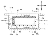
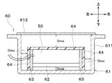
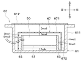
- the battery pack 60 according to the present embodiment will be described with reference to FIG.
- the case 61 is an accommodating portion for fixing and accommodating the battery module 50 so that a space is formed between the case 61 and the battery module 50.
- resin aluminum, stainless steel, iron, copper, or the like is used.
- the material of the case 61 is most preferably an aluminum-plated resin.
- the case 61 is configured by combining the main body 611 and the lid member 612.
- the main body 611 is formed in a box shape having an opening on the upper side.
- the lid member 612 is formed so as to close the opening of the main body 611.
- a cooler 62 is provided outside the battery module 50.
- the cooler 62 is provided below the battery module 50.
- the cooler 62 is configured so that cooling water circulating in the low-temperature side circulation channel 30a flows.
- the cooler 62 is a cooling unit that cools the battery module 50 (that is, the first battery 41) with cooling water.
- a flat plate-shaped end plate 63 for holding the battery module 50 and the cooler 62 is provided on the left and right surfaces of the battery module 50 and the cooler 62, respectively.
- a heat storage material 64 is provided outside the battery module 50. More specifically, the heat storage material 64 is provided on the upper surface and front and rear surfaces of the battery module 50, the lower surface of the cooler 62, and the outer surface of the end plate 63 (that is, the surface opposite to the battery module 50 and the cooler 62). Have been.
- Each surface of the battery module 50 (that is, upper and lower surfaces, left and right surfaces, and front and rear surfaces) is covered with the heat storage material 64. In other words, the entire surface of the battery module 50 is covered with the heat storage material 64.
- the heat storage material 64 is a latent heat storage material that stores or radiates heat by utilizing the inflow and outflow of latent heat accompanying a phase change.
- a resin heat storage material containing a microcapsule latent heat storage material is used as the heat storage material 64.
- the microcapsule latent heat storage material is a heat storage material in which the latent heat storage material is enclosed in the microcapsule.
- a latent heat storage material having an entrance / exit temperature of the latent heat of 0 ° C. or less can be used.
- a latent heat storage material for example, a paraffin-based hydrocarbon, hydrate-based, metal-based, or water-based latent heat storage material can be used.
- a space is formed between each surface of the battery module 50 and the case 61. Specifically, a space is formed between the surface of the heat storage material 64 covering the entire surface of the battery module 50 and the inner wall surface of the case 61. In this space, air as gas exists. Note that a heat insulating material may be provided in a part of this space.
- the maximum distance between each surface of the battery module 50 and the case 61 is set to be equal to or less than a predetermined distance at which convection of air on the surface of the battery module 50 is suppressed.
- the maximum distance between each surface of the battery module 50 and the inner wall surface facing each surface of the battery module 50 in the case 61 is a predetermined distance at which the convection of air on the surface of the battery module 50 is suppressed. It is set to be less than the distance.
- the predetermined distance at which convection of air on the surface of the battery module 50 is suppressed is referred to as a convection suppression distance.
- the entire surface of the battery module 50 is covered with the heat storage material 64.
- the maximum distance Dm between the surface of each heat storage material 64 covering each surface of the battery module 50 and the inner wall surface of the case 61 facing the surface of the heat storage material 64 is equal to or less than the convection suppression distance. It is set as follows.
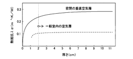
- the relationship between the thickness in the air layer and the thermal resistance is shown in FIG.
- the thermal resistance of the air layer is substantially constant. Therefore, for example, 1.5 cm can be adopted as the convection suppression distance.
- the maximum distance between each surface of the battery module 50 and the inner wall surface of the case 61 facing each surface of the battery module 50 is set to 1.5 cm or less.
- the maximum distance Dm between the surface of each heat storage material 64 covering each surface of the battery module 50 and the inner wall surface of the case 61 facing the surface of each heat storage material 64 is 1. It is set to 5 cm or less.
- the maximum distance Dm between the surface of the heat storage material 64 covering the upper surface of the battery module 50 and the inner wall surface of the case 61 facing the surface of the heat storage material 64 is referred to as the upper maximum distance Dma.
- the maximum distance Dm between the surface of the heat storage material 64 covering the lower surface of the cooler 62 and the inner wall surface of the case 61 facing the surface of the heat storage material 64 is referred to as a lower maximum distance Dmb.
- the surface of the end plate 63 opposite to the bonding surface with the battery module 50 is referred to as a side surface 63a.
- the maximum distance Dm between the side surface 63a of the end plate 63 and the surface of the case 61 facing the side surface 63a is referred to as a maximum lateral distance Dmc.
- the upper maximum distance Dma, the lower maximum distance Dmb, and the lateral maximum distance Dmc are set to the same length.
- connection portion 65 for fixing the battery module 50 covered with the heat storage material 64 at a distance from the inner wall surface on the lower side of the case 61 is provided in the case 61.
- the connection portion 65 of the present embodiment is formed in a rod shape extending from the inner wall surface on the lower side of the case 61 toward the battery module 50 side.
- the thickness of the heat storage material 64 is referred to as t ts .
- the gap between the heat storage material 64 and the case 61 facing the heat storage material 64 is referred to as t air .
- the thickness t ts of the heat storage material 64 is set to be not more than 3 of the gap size t air between the heat storage material 64 and the case 61. Further, the thickness dimension t ts of the heat storage material 64 may be 1 mm.
- the supply of power from the first battery 41 to the inverter 33 and the motor generator 34 is interrupted by a first switch 47a.
- the supply of power from the second battery 42 to the inverter 33 and the motor generator 34 is interrupted by a second switch 48a.
- the battery capacity of each battery cell of the second battery 42 is smaller than the battery capacity of each battery cell of the first battery 41.
- the number of each battery cell of the second battery 42 is the same as the number of each battery cell of the first battery 41. Therefore, the battery capacity of the second battery 42 is smaller than the battery capacity of the first battery 41.
- the electric circuit 70 including the first battery 41, the second battery 42, the inverter 33, and the motor generator 34 includes a DC inlet 71, a charger 72, a DCDC converter 73, and the like.
- the DC inlet 71 is connected to a plug of the DC charging stand 74 when the first battery 41 and the second battery 42 are charged by the DC charging stand 74.
- the plug of the charger 72 is connected to the household outlet 75 when the first battery 41 and the second battery 42 are charged with household power.
- the DCDC converter 73 converts the voltage of the power supplied from the first battery 41 and the second battery 42 to 12 V, and supplies the converted voltage to an auxiliary device 76 mounted on the vehicle.
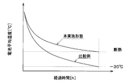
- FIG. 5 is a graph showing the relationship between the elapsed time after stopping the vehicle and the average battery temperature.
- the heat storage material was not provided in the battery, and no space was formed between each surface of the battery module 50 and the case 61.
- the amount of temperature decrease with respect to the elapsed time can be reduced as compared with the comparative example.
- FIG. 6 is a graph comparing the amount of heat required for warming up the battery between the embodiment and the comparative example.
- the amount of heat required for warming up the battery can be reduced as compared with the comparative example.
- FIG. 7 is a graph showing the relationship between battery temperature, battery output, and internal resistance in a lithium ion battery.
- a high output is obtained with a small capacity battery in a low temperature range, and a high output is obtained with a large capacity battery in an intermediate temperature range. In a high temperature range, the life of the battery is shortened.
- the battery in consideration of such characteristics of the lithium ion battery, the battery is operated according to the environmental temperature, the battery temperature, and the remaining battery level, so that the small capacity battery can be used all year without waste.
- a space is formed between each surface of the battery module 50 and the case 61. Then, air exists as a gas in the space formed between each surface of the battery module 50 and the case 61.
- the maximum distance Dm between each surface of the battery module 50 and the case 61 is set to be equal to or less than the convection suppression distance.
- the maximum distance Dm between the surface of the heat storage material 64 covering each surface of the battery module 50 and the inner wall surface of the case 61 facing the surface of the heat storage material 64 is defined as the convection suppression distance (for example, 1). .5 cm) or less.
- the space formed between each surface of the battery module 50 and the case 61 suppresses the convection of air on the surface of the battery module 50, and the amount of heat released from the battery module 50 to the case 61 via the space. Can be reduced. For this reason, since the heat insulation of the battery module 50 which is a heat source can be improved, the heat retention of the battery module 50 can be improved.
- the space formed between each surface of the battery module 50 and the case 61 in the present embodiment constitutes a convection suppressing portion and a heat radiation amount reducing portion.
- the case 61 that is a space forming part that forms the space is a member that forms the convection suppressing part and the heat radiation amount reducing part.
- the heat storage material 64 is provided outside the battery module 50. According to this, the heat generated in the battery module 50 can be stored in the heat storage material 64. When the outside air temperature (that is, the environmental temperature) decreases, the heat stored in the heat storage material 64 is released to the battery module 50, so that the temperature of the battery module 50 can be prevented from lowering. Thereby, the heat retention of the battery module 50 can be improved.
- a latent heat storage material is used as the heat storage material 64. According to this, when the environmental temperature is higher than the melting point of the latent heat storage material, heat is not stored in the heat storage material 64, so that the battery pack 60 of the present embodiment can be used as it is even at a high outside temperature such as summer. It becomes possible.
- the lower end of the end plate 63 projects downward from the lower end surface of the cooler 62.
- the lower end of the end plate 63 is connected to the inner wall surface on the lower side of the case 61.
- a space is formed between the lower surface of the cooler 62 and the case 61.
- the maximum distance between the upper surface of the battery module 50 and the inner wall surface of the case 61 facing the upper surface of the battery module 50 is referred to as an upper maximum distance Dma.
- the maximum distance between the lower surface of the cooler 62 and the inner wall surface of the case 61 facing the lower surface of the cooler 62 is referred to as a lower maximum distance Dmb.
- the maximum distance between the side surface 63a of the end plate 63 and the surface of the case 61 facing the side surface 63a of the end plate 63 is referred to as a maximum lateral distance Dmc.
- the upper maximum distance Dma, the lower maximum distance Dmb, and the lateral maximum distance Dmc are each set to be equal to or less than the convection suppression distance. Furthermore, in the present embodiment, the upper maximum distance Dma is set to be longer than the lateral maximum distance Dmc, and the lower maximum distance Dmb is set to be shorter than the lateral maximum distance Dmc.
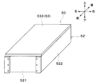
- the configuration of the battery module 50 is changed from the first embodiment. Specifically, the heat storage material 64 that covers the outside of the battery module 50 is eliminated, and the insulating plate 53 that is a part of the constituent members of the battery module 50 is formed of the heat storage material.
- the battery module 50 includes a battery cell 51, a frame 52, an insulating plate 53, and the like.
- the battery cell 51 is a heat source that generates heat as it is charged and discharged.
- the plurality of battery cells 51 are stacked in the front-rear direction to form a stacked body 510.
- the frame 52 is made of metal.
- the frame body 52 is formed in a square tubular shape so as to cover the left and right surfaces and the front and rear surfaces of the stacked body 510 of the battery cells 51. Openings (not shown) are formed on the upper and lower surfaces of the frame 52.
- the frame body 52 is formed by combining two first metal members 521 and two second metal members 522.
- the first metal member 521 is a rectangular plate-shaped member.
- the first metal member 521 is formed so as to cover the front and rear surfaces of the stacked body 510 of the battery cell 51.
- the second metal member 522 has a U-shaped cross section perpendicular to the vertical direction (in other words, a bathtub shape).
- the second metal member 522 is formed to cover the stacked body 510 of the battery cell 51 from the left side and the right side.
- the first metal member 521 and the second metal member 522 are integrally connected by a fastening member such as a screw.
- the insulating plate 53 is an insulating member provided between the stacked body 510 of the battery cell 51 and the case 61.
- the insulating plate 53 is made of a resin heat storage material containing a microcapsule heat storage material. For this reason, the insulating plate 53 has a heat storage material at least partially. That is, the insulating plate 53 has a heat storage function.
- microcapsule heat storage material As the microcapsule heat storage material, the same microcapsule latent heat storage material as in the first embodiment can be employed.
- the insulating plate 53 is formed in a rectangular plate shape.
- the insulating plates 53 are arranged one by one so as to cover each surface (ie, upper and lower surfaces, left and right surfaces, and front and rear surfaces) of the stacked body 510 of the battery cells 51.
- first insulating plates 531 two first insulating plates 531, two second insulating plates 532, and two third insulating plates 533 are provided as the insulating plates 53.
- the first insulating plate 531 is arranged so as to cover the front surface and the rear surface of the stacked body 510 of the battery cell 51, respectively.
- the second insulating plate 532 is arranged so as to cover the left surface and the right surface of the stacked body 510 of the battery cell 51, respectively.
- the third insulating plate 533 is disposed so as to cover the upper surface and the lower surface of the stacked body 510 of the battery cell 51, respectively.
- the first insulating plate 531 and the second insulating plate 532 are arranged inside the frame 52. That is, the first insulating plate 531 and the second insulating plate 532 are arranged between the stacked body 510 of the battery cell 51 and the frame 52. Thereby, the battery cell 51 and the frame 52 are insulated from each other.
- the third insulating plate 533 is arranged so as to close the openings formed on the upper and lower surfaces of the frame 52.
- the insulating plate 53 which is a part of the components of the battery module 50, is formed of a heat storage material. According to this, since it is not necessary to separately provide a heat storage material outside the battery module 50, the number of components does not increase. Therefore, the heat retention of the battery module 50 can be improved while reducing the manufacturing cost.
- the lower end of the end plate 63 projects downward from the lower end surface of the cooler 62.
- the lower end of the end plate 63 is connected to the inner wall surface on the lower side of the case 61.
- a space is formed between the lower surface of the cooler 62 and the case 61.
- the maximum distance between the lower surface of the cooler 62 and the inner wall surface of the case 61 facing the lower surface of the cooler 62 is referred to as a maximum lower distance Dmb.
- the upper maximum distance Dma, the lower maximum distance Dmb, and the lateral maximum distance Dmc are each set to be equal to or less than the convection suppression distance. Further, in the present embodiment, the upper maximum distance Dma and the lateral maximum distance Dmc are set to be the same length, and the lower maximum distance Dmb is set shorter than the upper maximum distance Dma and the lateral maximum distance Dmc.
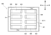
- a plurality of (eight in this example) battery modules 50 are housed in a case 61.
- the heat storage material 64 is arranged so as to cover all of the plurality of battery modules 50.
- the maximum distance Dm between each surface of the heat storage material 64 and the inner wall surface facing each surface of the heat storage material 64 in the case 61 is set to be equal to or less than the convection suppression distance.
- the heat storage material 64 is arranged so as to cover all of the plurality of battery modules 50 in one case 61. Therefore, the number of heat storage materials 64 can be reduced as compared with the case where heat storage materials 64 are arranged so as to cover each battery module 50 one by one. Therefore, the heat retention of the plurality of battery modules 50 can be improved while suppressing an increase in the number of components.
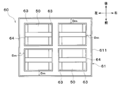
- a plurality of (two in this example) battery modules 50 are set as one set, and the heat storage material 64 is arranged so as to cover the set of battery modules 50 collectively.
- the case 61 a plurality of sets (four in this example) of one set of battery modules 50 covered with the heat storage material 64 are arranged. That is, a plurality of heat storage materials 64 configured to cover one set of battery modules 50 are arranged in the case 61.
- the maximum distance Dm between each surface of the plurality of heat storage materials 64 facing the case 61 and the inner wall surface of the case 61 is set to be equal to or less than the convection suppression distance.
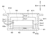
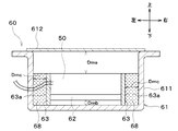
- a plate member 67 facing at least the surface of the battery module 50 is provided in the space inside the case 61.
- the plate member 67 is arranged so as to cover the surface of the battery module 50.
- the plate-shaped member 67 is arranged with a space between the battery module 50 and the battery module 50 so as not to contact the battery module 50.
- the plate member 67 is made of metal (aluminum in this example). In the present embodiment, the plate member 67 is formed integrally with a part of the case 61.
- the plate-shaped member 67 has an upper surface portion 671 facing the upper surface of the battery module 50 and a side surface portion 672 facing the side surface 63a of the end plate 63.
- the maximum distance between the upper surface of the battery module 50 and the upper surface 671 of the plate member 67 is referred to as an upper first maximum distance Dma1.
- the maximum distance between the upper surface 671 of the plate member 67 and the cover member 612 of the case 61 is referred to as an upper second maximum distance Dma2.
- the maximum distance between the side surface 63a of the end plate 63 and the side surface portion 672 of the plate member 67 is referred to as a first lateral maximum distance Dmc1.
- the maximum distance between the side surface portion 672 of the plate member 67 and the inner wall surface of the case 61 facing the side surface portion 672 is referred to as a second maximum lateral distance Dmc2.
- the upper first maximum distance Dma1, the lower maximum distance Dmb, and the first lateral maximum distance Dmc1 are each set to be less than or equal to the convection suppression distance. Further, in the present embodiment, the upper first maximum distance Dma1 is set to be longer than the first lateral maximum distance Dmc1, and the lower maximum distance Dmb is set to be shorter than the first lateral maximum distance Dmc1.
- the upper first maximum distance Dma1 and the upper second maximum distance Dma2 are set to the same length.
- the first lateral maximum distance Dmc1 and the second lateral maximum distance Dmc2 are set to the same length.
- the plate member 67 facing at least the surface of the battery module 50 is provided in the space inside the case 61. According to this, the convection of air on the surface of the battery module 50 can be suppressed by the plate-shaped member 67. Therefore, the plate-shaped member 67 of the present embodiment corresponds to a convection suppressing portion.
- the plate-shaped member 67 in the space inside the case 61, heat radiation from the battery module 50 can be shielded. That is, the plate member 67 can suppress heat radiation from the battery module 50. Therefore, the plate-shaped member 67 of the present embodiment corresponds to a shielding plate and a heat radiation suppressing portion.
- the plate-shaped member 67 suppresses the heat radiation from the battery module 50 while suppressing the convection of the air on the surface of the battery module 50, and is released from the battery module 50 to the case 61 via the space. Can be reliably reduced. Thereby, the heat insulation of the battery module 50 can be further improved, and the heat insulation of the battery module 50 can be further improved. Therefore, the plate-shaped member 67 of the present embodiment corresponds to a heat radiation amount reducing unit.
- the gap between the battery module 50 and the case 61 is divided by the plate-shaped member 67 by providing the plate-shaped member 67 in the space inside the case 61. Accordingly, even in the battery pack 60 in which the gap between the battery module 50 and the case 61 is large, the maximum distance between the surface of the battery module 50 and the plate member 67 facing the surface of the battery module 50 is equal to or less than the convection suppression distance.
- the maximum distance between the surface of the battery module 50 and the plate member 67 facing the surface of the battery module 50 may be 0 mm. That is, the battery module 50 and the plate member 67 may be in close contact with each other.
- the distance between the plate member 67 and the inner wall surface of the case 61 facing the plate member 67 is set to be larger than 0 mm and equal to or less than the convection suppression distance (1.5 cm in this example). That is, the plate member 67 and the case 61 are not in close contact with each other.
- the plate-shaped member 67 of this embodiment is made of a resin heat storage material containing a microcapsule heat storage material. For this reason, the plate-shaped member 67 has a heat storage function.
- the microcapsule heat storage material the same microcapsule latent heat storage material as in the first embodiment can be used.
- the maximum distance between each surface of the battery module 50 and the plate member 67 is set shorter than the maximum distance between the plate member 67 and the case 61. That is, the upper first maximum distance Dma1 is set shorter than the upper second maximum distance Dma2. Further, the first lateral maximum distance Dmc1 is set shorter than the second lateral maximum distance Dmc2.
- the heat generation in the battery module 50 is easily stored in the plate member 67. Therefore, the heat storage of the battery pack 60 can be improved, and the heat retention of the battery module 50 can be improved.
- the upper first maximum distance Dma1, the lower maximum distance Dmb, and the first lateral maximum distance Dmc1 are set to the same length.
- the upper second maximum distance Dma2 is set to be longer than the second lateral maximum distance Dmc2, and the lower maximum distance Dmb is set to be shorter than the second lateral maximum distance Dmc2.
- a sealed portion 68 in which a gas containing a rare gas, such as argon gas, is sealed is provided in the case 61.
- the concentration of the argon gas in the gas sealed in the sealing portion 68 is higher than the concentration of the argon gas in the air.
- the enclosing portion 68 is disposed between the side surface 63 a of the end plate 63 and the case 61.
- the sealing portion 68 of the present embodiment corresponds to a heat conduction suppressing portion and a heat radiation amount reducing portion.
- a heat insulating structure using a vacuum heat insulating material instead of the sealing portion 68 of the present embodiment is referred to as a heat insulating structure of a comparative example.
- the manufacturing cost can be reduced as compared with the heat insulating structure of the comparative example.
- the material of the insulating plate 53 and the plate-shaped member 67 is not limited to the resin heat storage material.
- the insulating plate 53 and the plate-shaped member 67 may be made of a rubber heat storage material (in other words, a heat storage rubber material).
- the example in which the plate-shaped member 67 is made of metal has been described, but the material of the plate-shaped member 67 is not limited to this.
- the plate member 67 may be made of resin.
- argon gas was used as the rare gas sealed in the sealing portion 68, but the rare gas is not limited to this.
- neon gas, krypton gas, or xenon gas may be used as the rare gas sealed in the sealing portion 68.
- the performance of suppressing heat conduction from the battery module 50 to the case 61 in the sealing section 68 increases in the order of neon gas, argon gas, krypton gas, and xenon gas.
- the cooler 62 is provided below the battery module 50
- the configuration below the battery module 50 is not limited to this.
- a heater for heating the battery module 50 may be provided below the battery module 50, or both the cooler 62 and the heater may be provided. Further, the cooler 62 may be omitted.
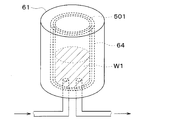
- the heat retention device may be applied to a hot water tank 501 that stores hot water W1.
- the hot water W1 stored in the hot water tank 501 corresponds to the heat source.
- the heat retention device may be applied to a catalyst device 503 supporting a catalyst 502.
- the catalyst device 503 is disposed in an exhaust pipe 504 through which exhaust gas from an internal combustion engine (not shown) flows.
- the catalyst 502 corresponds to a heat source.
- the enclosing portion 68 is arranged between the side surface 63a of the end plate 63 and the case 61 , but the arrangement of the enclosing portion 68 is not limited to this.
- the sealing section 68 may be arranged around the battery module 50.
- the sealed portion 68 in which a gas containing a rare gas is sealed is employed as the heat conduction suppressing portion, but the heat conduction suppressing portion is not limited to this.
- part or all of the enclosing portion 68 may be changed to a vacuum heat insulating material. Thereby, heat insulation performance (that is, heat conduction suppression performance) can be improved.
- a vacuum heat insulating material is provided in the gap, and the sealing portion 68 is provided in another wide gap. Is also good. That is, a vacuum heat insulating material is provided between the left and right side surfaces of the battery module 50 and the case 61 and between the lower surface of the battery module 50 and the case 61, and sealed between the upper surface of the battery module 50 and the case 61. A portion 68 may be provided. According to this, the manufacturing cost can be reduced as compared with the case where the vacuum heat insulating material is provided in all the gaps between the battery module 50 and the case 61.
- the heat source is not limited to these.
- an inverter, a motor, an ECU, or the like which is a device that generates heat by electric energy, may be employed as the heat source.
Landscapes
- Engineering & Computer Science (AREA)
- Manufacturing & Machinery (AREA)
- Chemical & Material Sciences (AREA)
- Chemical Kinetics & Catalysis (AREA)
- Electrochemistry (AREA)
- General Chemical & Material Sciences (AREA)
- Physics & Mathematics (AREA)
- Thermal Sciences (AREA)
- Mechanical Engineering (AREA)
- General Engineering & Computer Science (AREA)
- Secondary Cells (AREA)
- Battery Mounting, Suspending (AREA)
Applications Claiming Priority (2)
| Application Number | Priority Date | Filing Date | Title |
|---|---|---|---|
| JP2018-140227 | 2018-07-26 | ||
| JP2018140227A JP7070200B2 (ja) | 2018-07-26 | 2018-07-26 | 保温装置 |
Publications (1)
| Publication Number | Publication Date |
|---|---|
| WO2020022065A1 true WO2020022065A1 (ja) | 2020-01-30 |
Family
ID=69180983
Family Applications (1)
| Application Number | Title | Priority Date | Filing Date |
|---|---|---|---|
| PCT/JP2019/027362 Ceased WO2020022065A1 (ja) | 2018-07-26 | 2019-07-10 | 保温装置 |
Country Status (2)
| Country | Link |
|---|---|
| JP (1) | JP7070200B2 (enExample) |
| WO (1) | WO2020022065A1 (enExample) |
Cited By (2)
| Publication number | Priority date | Publication date | Assignee | Title |
|---|---|---|---|---|
| CN111540920A (zh) * | 2020-05-09 | 2020-08-14 | 中国工程物理研究院电子工程研究所 | 一种热电池真空全覆盖式保温结构及其应用 |
| CN113285146A (zh) * | 2021-07-22 | 2021-08-20 | 华东交通大学 | 一种电动汽车电池保温装置及方法 |
Families Citing this family (1)
| Publication number | Priority date | Publication date | Assignee | Title |
|---|---|---|---|---|
| JP2024058366A (ja) * | 2022-10-14 | 2024-04-25 | 豊田合成株式会社 | 車両用電池ケースおよび車両用電池ケースのアッパケース |
Citations (4)
| Publication number | Priority date | Publication date | Assignee | Title |
|---|---|---|---|---|
| JPS6273579A (ja) * | 1985-09-26 | 1987-04-04 | Kawasaki Heavy Ind Ltd | ナトリウム−イオウ電池 |
| JPH1032021A (ja) * | 1996-05-17 | 1998-02-03 | Daihatsu Motor Co Ltd | バッテリ保温カバー |
| JP2015002108A (ja) * | 2013-06-17 | 2015-01-05 | 住友電気工業株式会社 | 二次電池システム |
| JP2016105365A (ja) * | 2014-12-01 | 2016-06-09 | マツダ株式会社 | 自動車のバッテリー保護装置 |
-
2018
- 2018-07-26 JP JP2018140227A patent/JP7070200B2/ja active Active
-
2019
- 2019-07-10 WO PCT/JP2019/027362 patent/WO2020022065A1/ja not_active Ceased
Patent Citations (4)
| Publication number | Priority date | Publication date | Assignee | Title |
|---|---|---|---|---|
| JPS6273579A (ja) * | 1985-09-26 | 1987-04-04 | Kawasaki Heavy Ind Ltd | ナトリウム−イオウ電池 |
| JPH1032021A (ja) * | 1996-05-17 | 1998-02-03 | Daihatsu Motor Co Ltd | バッテリ保温カバー |
| JP2015002108A (ja) * | 2013-06-17 | 2015-01-05 | 住友電気工業株式会社 | 二次電池システム |
| JP2016105365A (ja) * | 2014-12-01 | 2016-06-09 | マツダ株式会社 | 自動車のバッテリー保護装置 |
Cited By (2)
| Publication number | Priority date | Publication date | Assignee | Title |
|---|---|---|---|---|
| CN111540920A (zh) * | 2020-05-09 | 2020-08-14 | 中国工程物理研究院电子工程研究所 | 一种热电池真空全覆盖式保温结构及其应用 |
| CN113285146A (zh) * | 2021-07-22 | 2021-08-20 | 华东交通大学 | 一种电动汽车电池保温装置及方法 |
Also Published As
| Publication number | Publication date |
|---|---|
| JP7070200B2 (ja) | 2022-05-18 |
| JP2020017426A (ja) | 2020-01-30 |
Similar Documents
| Publication | Publication Date | Title |
|---|---|---|
| JP5949522B2 (ja) | 温調装置 | |
| RU2708148C1 (ru) | Аккумуляторный блок | |
| CN102470724B (zh) | 车辆用空调系统 | |
| EP4215386A1 (en) | Vehicle thermal management system and electric vehicle | |
| US8584780B2 (en) | Device for cooling the batteries of an especially electric vehicle and vehicle comprising such a device | |
| JP5757502B2 (ja) | バッテリ温度調節ユニット及びバッテリ温度調節装置 | |
| EP2501573B1 (en) | Cooling arrangement for at least one battery in a vehicle | |
| WO2018047539A1 (ja) | 機器温調装置 | |
| JPH11307139A (ja) | 電池冷却装置 | |
| WO2018235473A1 (ja) | 端子冷却装置 | |
| US10906141B2 (en) | Method for manufacturing device temperature control device and method for filling working fluid | |
| JPWO2012114439A1 (ja) | 車載用バッテリの温度制御システム | |
| WO2018047538A1 (ja) | 機器温調システム | |
| US20210206292A1 (en) | Temperature-control element with sorption material, in particular for controlling the temperature of a battery cell unit of a motor vehicle | |
| WO2018047533A1 (ja) | 機器温調装置 | |
| WO2013111529A1 (ja) | 電池温調装置 | |
| WO2020022065A1 (ja) | 保温装置 | |
| CN110571494A (zh) | 车辆用电池的冷却构造 | |
| JP7263713B2 (ja) | 保温装置 | |
| JP2024001400A (ja) | 車両用熱マネジメントシステム | |
| WO2020100846A1 (ja) | 熱管理システム | |
| US10483602B2 (en) | Battery housing for a lithium-ion battery | |
| JP2014144668A (ja) | 車両用空調装置 | |
| KR102574693B1 (ko) | 전기차량의 하이브리드형 배터리 열관리 시스템 | |
| JP5796532B2 (ja) | 温調装置 |
Legal Events
| Date | Code | Title | Description |
|---|---|---|---|
| 121 | Ep: the epo has been informed by wipo that ep was designated in this application |
Ref document number: 19842091 Country of ref document: EP Kind code of ref document: A1 |
|
| NENP | Non-entry into the national phase |
Ref country code: DE |
|
| 122 | Ep: pct application non-entry in european phase |
Ref document number: 19842091 Country of ref document: EP Kind code of ref document: A1 |