WO2020021946A1 - 定着装置および画像形成装置 - Google Patents
定着装置および画像形成装置 Download PDFInfo
- Publication number
- WO2020021946A1 WO2020021946A1 PCT/JP2019/025373 JP2019025373W WO2020021946A1 WO 2020021946 A1 WO2020021946 A1 WO 2020021946A1 JP 2019025373 W JP2019025373 W JP 2019025373W WO 2020021946 A1 WO2020021946 A1 WO 2020021946A1
- Authority
- WO
- WIPO (PCT)
- Prior art keywords
- curved surface
- pressing
- fixing belt
- fixing
- nip
- Prior art date
- Legal status (The legal status is an assumption and is not a legal conclusion. Google has not performed a legal analysis and makes no representation as to the accuracy of the status listed.)
- Ceased
Links
Images




Classifications
-
- G—PHYSICS
- G03—PHOTOGRAPHY; CINEMATOGRAPHY; ANALOGOUS TECHNIQUES USING WAVES OTHER THAN OPTICAL WAVES; ELECTROGRAPHY; HOLOGRAPHY
- G03G—ELECTROGRAPHY; ELECTROPHOTOGRAPHY; MAGNETOGRAPHY
- G03G15/00—Apparatus for electrographic processes using a charge pattern
- G03G15/20—Apparatus for electrographic processes using a charge pattern for fixing, e.g. by using heat
- G03G15/2003—Apparatus for electrographic processes using a charge pattern for fixing, e.g. by using heat using heat
- G03G15/2014—Apparatus for electrographic processes using a charge pattern for fixing, e.g. by using heat using heat using contact heat
- G03G15/2053—Structural details of heat elements, e.g. structure of roller or belt, eddy current, induction heating
-
- G—PHYSICS
- G03—PHOTOGRAPHY; CINEMATOGRAPHY; ANALOGOUS TECHNIQUES USING WAVES OTHER THAN OPTICAL WAVES; ELECTROGRAPHY; HOLOGRAPHY
- G03G—ELECTROGRAPHY; ELECTROPHOTOGRAPHY; MAGNETOGRAPHY
- G03G15/00—Apparatus for electrographic processes using a charge pattern
- G03G15/20—Apparatus for electrographic processes using a charge pattern for fixing, e.g. by using heat
Definitions
- the present invention relates to a fixing device for fixing a toner image on a sheet, and an image forming apparatus provided with the fixing device.
- the image forming apparatus includes a fixing device that fixes the toner image formed on the sheet.
- the fixing device includes a fixing member that heats the toner image formed on the sheet and a pressing member that presses the toner image against the sheet.
- the fixing device employs, for example, a fixing belt as a fixing member in order to reduce the heat capacity of the fixing member and shorten the warm-up time, and the fixing belt is heated by a heat source such as an IH unit.
- a nip forming member such as a pad that sandwiches the fixing belt together with the pressing member and forms a fixing nip between the fixing belt and the pressing member is provided inside the fixing belt.
- the fixing device disclosed in Patent Document 1 is fixed to the inner peripheral surface side of the fixing belt, supports the fixing belt, heats the fixing belt by heating with a heat source, and faces the pressing roller (pressing member).
- a heat transfer member having an opening at a position; and a fixing member (nip forming member) provided at the opening of the heat transfer member and pressed against a pressure roller via a fixing belt.
- the fixing device of Patent Document 2 includes an endless rotatable fixing belt, a heating element (heat source) disposed inside the fixing belt, and a nip member (nip formation) disposed at a distance from the heating element. And a backup member (pressing member) for forming a nip portion between the fixing belt and the fixing belt by sandwiching the fixing belt between the fixing belt and the nip member.
- the nip member has a protruding portion that protrudes toward the backup member on the downstream side or the upstream side in the rotation direction of the fixing belt.
- the fixing surface of the fixing belt facing the pressing member is formed based on the shape of the pressing surface of the nip forming member on the fixing belt side.
- the pressing surface of the nip forming member is formed parallel to the paper conveyance direction when entering the fixing device, and the fixing surface of the fixing belt is planar. May be molded.
- the pressure member is formed in a cylindrical shape, the contact area of the pressure member with the fixing surface of the flat fixing belt is small, and the nip width is short. Since the fixing surface of the flat fixing belt linearly retreats the sheet after fixing, the sheet hardly separates from the fixing belt.
- the nip forming member may form a curved surface on the fixing surface of the fixing belt by providing a protruding portion or the like on the downstream side or the upstream side in the rotation direction of the fixing belt as in Patent Document 2.
- the inflection point of the curved surface of the fixing surface is more concave than the surroundings, the pressure applied by the pressing member does not sufficiently reach the inflection point, and pressure is released in the fixing nip.
- the sheet on which the toner image is formed is conveyed on the fixing surface, there is a possibility that the sheet slightly slips at the position where the pressure loss occurs, resulting in image quality deterioration such as image shift.
- the toner on the paper is not sufficiently melted and exists in a granular state. For this reason, when the inflection point is on the upstream side in the rotation direction of the fixing belt, if pressure loss occurs, the toner particles easily move, so that a minute image shift easily occurs.
- the nip forming member may be formed in a single curved arc shape having a single radius of curvature along the outer peripheral surface of the pressing member, and in this case, the fixing belt may be formed in a single curved arc shape.
- the fixing nip is also formed in a single curved arc shape. Plain paper easily deforms along the fixing belt with respect to the fixing nip having a single curve, but strong paper such as thick paper does not easily deform along the fixing belt. Depending on the position in the transport direction, a sufficient nip pressure may not be obtained.
- the paper S0 having a strong stiffness is formed at a position on an extension line parallel to the pressing direction of the pressing member 101 and passing through the center of the pressing member 101 (that is, the pressing center P0). Also, a load for pressing the sheet S0 toward the fixing belt 101 (the nip forming member 102 having a single curve) is easily applied by the pressing member 101, and a sufficient nip pressure is obtained as shown in FIG.
- the vicinity of the entrance N0a and the vicinity of the exit N0b of the fixing nip N0 in the transport direction of the paper S0 that is, the vicinity of the edges 102a and 102b of the nip forming member 102 are fulcrums when the paper S0 having a strong stiffness is pushed in the pressing direction. Since the sheet S0 comes into close contact with the fixing belt 101, a load is easily applied, and a sufficient nip pressure can be obtained.
- the inflection point due to the shape of the nip forming member is provided at a position where a load is hardly applied between the vicinity of the entrance or the exit of the arc-shaped fixing nip and the center of pressure as described above. In this case, pressure drop occurs more remarkably.
- the object of the present invention is to increase the nip width of the fixing nip, improve the sheet separation property, and suppress the pressure drop.
- the fixing device of the present invention includes a rotatable fixing belt, a rotatable pressure member, and a nip forming member.
- the fixing belt is heated by the heat source and heats the toner image formed on the sheet.
- the pressing member is pressed against the fixing belt, and presses the sheet passing between the fixing belt and the fixing belt.
- the nip forming member is provided inside the fixing belt, and forms a fixing nip between the fixing belt and the pressing member by sandwiching the fixing belt together with the pressing member.
- the nip forming member extends in a nip width direction that intersects a pressing direction of the pressing member and a rotation axis direction, and a pressing surface of the nip forming member on a side of the pressing member is in a conveying direction of the sheet.
- the first curved surface is formed in an arc shape curved toward the pressure member toward the upstream side in the transport direction
- the second curved surface is formed on the pressure member toward the downstream side in the transport direction. It is formed in an arc shape curved to the side.
- the first curved surface and the second curved surface are continuous by providing an inflection point near an intersection on the pressing surface of an extension line that is parallel to the pressing direction and passes through the rotation center of the pressing member,
- One curved surface has a larger radius of curvature than the second curved surface.
- the image forming apparatus of the present invention includes the above-described fixing device.
- the present invention it is possible to increase the nip width of the fixing nip, improve the sheet separating property, and further suppress the pressure drop.
- FIG. 1 is a cross-sectional view illustrating a printer according to an embodiment of the invention.
- FIG. 1 is a cross-sectional view illustrating a fixing device according to an embodiment of the present disclosure.
- FIG. 2 is a cross-sectional view illustrating a pad of a fixing device according to an embodiment of the present invention and a peripheral portion thereof.
- 5 is a graph illustrating a nip pressure according to a position in a transport direction when a sheet is passed through a fixing nip in a fixing device according to an embodiment of the present disclosure.
- FIG. 9 is a cross-sectional view illustrating a nip forming member of a conventional fixing device and its peripheral portion. 9 is a graph illustrating a nip pressure according to a position in a conveyance direction when thick paper is passed through a fixing nip in a conventional fixing device.
- the printer 1 image forming apparatus
- FIG. 1 the front side of the paper surface in FIG. Arrows L, R, U, and Lo attached to the drawings as appropriate indicate the left side, right side, upper side, and lower side of the printer 1, respectively.
- the printer 1 includes a substantially box-shaped printer main body 2, a paper feed cassette for storing paper is provided at a lower portion of the printer main body 2, and a paper discharge tray is provided at an upper portion of the printer main body 2.
- the printer 1 may be provided with one paper feed cassette so as to store a single size and a single type of paper, but may be different in size (for example, A4 size or A3 size) or different type (plain paper, A plurality of paper feed cassettes may be provided so as to store paper such as thick paper.
- an exposure device composed of a laser scanning unit (LSU) is arranged below the paper discharge tray.
- An image forming unit 5 is provided below the exposure device in the printer main body 2.
- a photosensitive drum 6 as an image carrier is rotatably provided.
- a charging device, a developing device connected to a toner container, a transfer roller, The cleaning device is disposed along the rotation direction of the photosensitive drum 6.
- a paper transport path 10 is provided inside the printer main body 2.
- a paper feed unit 11 is provided near the paper feed cassette at an upstream end of the transport path 10, and a transfer unit 12 including the photosensitive drum 6 and a transfer roller is provided at a middle part of the transport path 10.
- a fixing device 13 is provided at a downstream portion of the transport path 10, and a paper discharge section 14 is provided at a downstream end of the transport path 10 near the paper discharge tray.
- a control device 15 for controlling the fixing device 13 is provided inside the printer main body 2.
- the control device 15 includes, for example, a control circuit such as a CPU and a storage device such as a ROM and a RAM.
- the printer 1 starts an image forming operation. At this time, the size and type of paper to be printed are specified.
- the image forming operation first, after the surface of the photosensitive drum 6 is charged by the charging device of the image forming unit 5, exposure corresponding to the image data is performed on the photosensitive drum 6 by laser light from the exposure device. Then, an electrostatic latent image is formed on the surface of the photosensitive drum 6. Next, the developing device of the image forming unit 5 develops the electrostatic latent image into a toner image using toner.
- sheets of a specified size and type are taken out by the sheet feeding unit 11 and conveyed on the conveyance path 10.
- the paper on the transport path 10 is transported to the transfer unit 12 at a predetermined timing, and the transfer unit 12 transfers the toner image on the photosensitive drum 6 to the paper.
- the sheet on which the toner image has been transferred is conveyed to the fixing device 13, and the fixing device 13 fixes the toner image on the sheet.
- the paper on which the toner image has been fixed is discharged from the paper discharge unit 14 to a paper discharge tray.
- the fixing device 13 includes a fixing belt 20, a pressure roller 21 (pressure member), a heat source 22, a support member 23, a pad 24 (nip forming member), and a sliding sheet 25. , A belt guide 26, and an electric component holder 27.
- the support member 23 and the sliding sheet 25 are omitted for convenience of explanation.
- the fixing belt 20 and the pressure roller 21 are respectively disposed on the upper side and the lower side of the substantially box-shaped fixing frame (not shown) with the transport path 10 interposed therebetween, and are disposed so as to be opposed to and in contact with each other. You.
- the fixing frame is attached to the printer main body 2 so that the conveyance path 10 penetrates the fixing frame in the sheet conveyance direction (left-right direction).
- a fixing nip N in a predetermined pressure area is formed between the fixing belt 20 and the pressure roller 21.
- the pressure area is an area where the fixing belt 20 and the pressure roller 21 are in contact with each other, and is a position on the upstream side in the transport direction where the pressure on the sheet by the fixing belt 20 and the pressure roller 21 is 0 Pa. To the downstream position in the transport direction where the pressure becomes 0 Pa again through the position in the transport direction where the pressure becomes maximum.
- the fixing belt 20 is a flexible endless belt, is formed in a cylindrical shape having a length of 30 mm in outer diameter, which is long in the width direction (front-back direction) of the paper orthogonal (intersecting) with the transport direction of the paper.
- the fixing belt 20 includes, for example, a heating layer, an elastic layer provided around the heating layer, and a release layer covering the elastic layer.
- the heating layer is formed of a metal material such as nickel electrocast having a thickness of about 30 to 50 ⁇ m
- the elastic layer is formed of an elastic material such as silicon rubber having a thickness of about 200 to 500 ⁇ m
- the release layer is formed of It is formed of a fluorine-based resin material such as PFA.
- the inner peripheral surface of the fixing belt 20 is coated with a heat-resistant resin such as PTFE.
- the fixing belt 20 is rotatably attached to the fixing frame with the front-rear direction being the rotation axis direction, and is rotated by the rotation of the pressure roller 21.
- the lower side (the pad 24 side) of the fixing belt 20 is formed along the shape of the pad 24.
- the fixing belt 20 is heated by the heat source 22.
- the heating layer of the fixing belt 20 is induction-heated by the magnetic flux generated by the heat source 22, and contacts the paper on which the toner image is formed to heat the toner image.
- the pressure roller 21 is formed in a columnar shape having a length of 30 mm in outer diameter and being long in the width direction of the sheet.
- the pressure roller 21 is composed of, for example, a columnar metal core material and a resin elastic layer of silicon rubber or the like having a thickness of about 5 mm provided around the core material, and the elastic layer is made of PFA or the like. It is covered with a release layer of a fluororesin.
- the pressure roller 21 is rotatably attached to the fixing frame with the front-rear direction being the rotation axis direction.
- the core of the pressure roller 21 is connected to a drive source (not shown) such as a motor, and is rotated by a rotational driving force transmitted from the drive source, whereby the pressure roller 21 rotates.
- the pressure roller 21 is pressed toward the fixing belt 20 to form a fixing nip N between the fixing belt 20 and the pressure roller 21, and the sheet passing through the fixing nip N together with the fixing belt 20 is removed. Apply pressure.
- the pressure roller 21 is configured to apply a pressing force of, for example, 300 to 400 N toward the fixing belt 20.
- the heat source 22 is long in the rotation axis direction of the fixing belt 20, has an arc-shaped cross section, is formed so as to cover the fixing belt 20, and is disposed outside (upper side) of the fixing belt 20. In other words, the heat source 22 is disposed on the opposite side of the fixing belt 20 from the pressing roller 21 at a predetermined interval from the fixing belt 20.
- the heat source 22 is, for example, an IH unit that causes the fixing belt 20 to perform induction heating (IH).
- the IH unit includes a bobbin 30, a coil 31, a center core 32, an arch core 33, and two rows of side cores.
- the IH unit generates a magnetic flux by passing an electric current through the coil 31, and causes the magnetic flux to act on the fixing belt 20, thereby causing the fixing belt 20 to perform induction heating (IH).
- a current flows through the coil 31 by being controlled by the control device 15 and supplied with power from a power supply (not shown).
- the control device 15 controls power supply to the heat source 22 so that the surface temperature of the fixing belt 20 detected by a temperature sensor (not shown) becomes a predetermined fixing temperature.
- the bobbin 30 is a plate member having an arc-shaped cross section along the curved surface (upper outer peripheral surface) of the fixing belt 20, and is disposed above the fixing belt 20.
- the coil 31 is wound on the outer peripheral surface of the bobbin 30 while reciprocating in the rotation axis direction of the fixing belt 20, and is formed along the outer peripheral surface of the fixing belt 20. Further, as described above, the coil 31 is an IH coil that generates a magnetic flux by flowing a current.
- the center core 32, the arch core 33, and the two rows of side cores 34 constitute a ferrite member for guiding the magnetic flux generated by the coil 31 to the fixing belt 20.
- the bobbin 30, the center core 32, the arch core 33, and the two rows of side cores 34 also serve as a case for storing the coil 31.
- the center core 32 is formed in a prismatic shape, and is disposed at the center in the left-right direction on the outer peripheral surface of the bobbin 30.
- the arch core 33 is a plate member having an arc-shaped cross section having a larger outer diameter than the bobbin 30, and is arranged on the opposite side of the bobbin 30 with the coil 31 interposed therebetween. Note that the bobbin 30 and the arch core 33 are arranged so as to be coaxial with the fixing belt 20.
- the two rows of side cores 34 are formed in a plate shape, and are arranged at both circumferential ends of the bobbin 30 and the arch core 33 so as to close a gap between the bobbin 30 and the arch core 33.
- the support member 23 is formed of, for example, a metal material in a rectangular tube shape longer in the front-rear direction than the fixing belt 20, and is disposed substantially at the center inside the fixing belt 20. Both ends in the front-rear direction of the support member 23 are supported by the fixing frame.
- the support member 23 is formed of a material and a shape having high mechanical strength to support the fixing belt 20 and components inside the fixing belt 20 and receive a pressing force from the pressure roller 21.
- the pad 24 is, for example, a heat-resistant resin such as LCP, and is a long member having the rotation axis direction of the fixing belt 20 as a longitudinal direction and a nip width direction orthogonal (intersecting) to the rotation axis direction as a short direction.
- the fixing nip N is extended in the lateral direction.
- the pad 24 is attached to the support member 23 on the pressure roller 21 side (lower side) of the support member 23 inside the fixing belt 20.
- the pad 24 is arranged such that the surface on the pressure roller 21 side (lower side), that is, the pressing surface 40 contacts the inner peripheral surface of the fixing belt 20 via the sliding sheet 25.
- the pad 24 receives a pressing force from the pressing roller 21 via the fixing belt 20, and presses the pressing roller 21 via the fixing belt 20 against the pressing force. As a result, the pad 24 sandwiches the fixing belt 20 with the pressing roller 21 to form a fixing nip N between the fixing belt 20 and the pressing roller 21.
- the pressing direction of the pressing roller 21 against the pad 24 is a direction from the rotation center of the pressing roller 21 to the rotation center of the fixing belt 20, that is, upward.
- the direction in which the fixing nip N extends along the pad 24 (nip width direction) is a direction orthogonal (intersecting) to the pressing direction and the rotation axis direction of the pressing roller 21, that is, the left-right direction.
- the pad 24 is arranged such that the center of the pad 24 in the nip width direction is located on an extension line A passing through the rotation center of the pressure roller 21 in parallel with the pressure direction of the pressure roller 21.
- the fixing nip N actually extends in the left-right direction since the contact area between the fixing belt 20 and the pressure roller 21 deformed along the pad 24 has a shape deformed along the pad 24. It does not have to be parallel to the left-right direction.
- the pressing surface 40 of the pad 24 on the pressure roller 21 side has a first curved surface 41 on the upstream side (the entrance side of the fixing nip N) and a second curved surface 42 on the downstream side (the exit side of the fixing nip N) in the sheet conveying direction.
- the first curved surface 41 is formed in an arc-shaped cross section curved toward the pressure roller 21 toward the upstream side in the transport direction
- the second curved surface 42 is curved toward the pressure roller 21 toward the downstream side in the transport direction. It is formed in a circular arc shape.
- the first curved surface 41 and the second curved surface 42 are continuous with an inflection point B provided near the intersection of the extension line A on the pressing surface 40, and the pad 24 has an upwardly concave cross-sectional shape.
- the cross-sectional shape of the pad 24 is a compound curved shape in which the pressing surface 40 with respect to the fixing nip N is constituted by a plurality of curves.
- the inflection point B of the first curved surface 41 and the second curved surface 42 may be provided at the center of pressure where the pressing surface 40 and the extension line A intersect, or from the extension line A in the sheet conveyance direction. It may be provided within a range of about ⁇ 1 mm. For example, it is preferable to provide the sheet at a position shifted by about 0.5 mm on the downstream side in the transport direction from the viewpoint of nip pressure distribution and image quality.
- the first radius of curvature Ra (radius of curvature) of the first curved surface 41 and the second radius of curvature Rb of the second curved surface 42 are larger than the radius Rp of the pressure roller 21.
- the first curvature radius Ra of the first curved surface 41 is formed to be larger than the second curvature radius Rb of the second curved surface 42.
- the center point of the second curved surface 42 forming the arc shape is provided below the center point of the pressure roller 21, and the center point of the first curved surface 41 forming the arc shape is the second curved surface 42 will be provided below the arc-shaped center point.
- the first curved surface 41 is formed with a first radius of curvature Ra of 80 mm or more
- the second curved surface 42 is formed of a first curved radius Ra of 40 mm or more. It may be formed with two curvature radii Rb.
- the pressing surface 40 of the pad 24 may be formed such that the second radius of curvature Rb of the second curved surface 42 is larger than twice the radius Rp of the pressure roller 21.
- the first radius of curvature Ra is about twice the second radius of curvature Rb, but the first radius of curvature Ra may be slightly larger than the second radius of curvature Rb.
- the first curved surface 41 may be formed by a straight line parallel to the nip width direction. In this case, the first curvature radius Ra of the first curved surface 41 is infinite.
- the sliding sheet 25 is formed of a material having flexibility, heat resistance, slidability, durability, and the like, is attached to the support member 23, and is interposed between the inner peripheral surface of the fixing belt 20 and the pad 24. Be mounted.
- the sliding sheet 25 is formed according to the shape of the pad 24.
- the sliding sheet 25 is in direct contact with the inner peripheral surface of the fixing belt 20 to reduce the sliding resistance between the fixing belt 20 and the pad 24 and secure the sliding performance of the fixing belt 20.
- a lubricant such as oil is applied to the sliding sheet 25 in order to improve the slidability.
- the sliding sheet 25 also suppresses abrasion between the fixing belt 20 and the pad 24.
- the belt guide 26 is formed of a magnetic SUS plate or the like having a thickness of about 0.2 to 0.3 mm and has an arc-shaped cross section along the upper side of the inner peripheral surface of the fixing belt 20.
- the belt guide 26 is disposed at a position facing the heat source 22 so that the arc-shaped outer peripheral surface is along the inner peripheral surface of the fixing belt 20, and is attached to the support member 23.
- the belt guide 26 contacts the inner peripheral surface of the fixing belt 20 and assists and stabilizes the rotation trajectory of the fixing belt 20. Further, the belt guide 26 absorbs the leakage magnetic flux transmitted through the fixing belt 20 to assist heat generation and reduces the leakage magnetic flux to the inside of the fixing belt 20.
- the electric component holder 27 is a member for mounting an electric component such as a temperature sensor disposed inside the fixing belt 20, and is attached to the support member 23 inside the belt guide 26.
- the fixing device 13 of the printer 1 is heated by the heat source 22 and the rotatable fixing belt 20 that heats the toner image formed on the sheet,
- a rotatable pressure roller 21 pressing member
- a pad 24 nip forming member
- the pad 24 extends in the nip width direction intersecting the pressing direction of the pressing roller 21 and the rotation axis direction, and the pressing surface 40 of the pad 24 on the pressing roller 21 side is located on the upstream side in the sheet conveying direction. It has one curved surface 41 and a second curved surface 42 on the downstream side.
- the first curved surface 41 is formed in an arc shape curved toward the pressure roller 21 toward the upstream side in the transport direction, and the second curved surface 42 is curved toward the pressure roller 21 toward the downstream side in the transport direction. It is formed in an arc shape.
- the first curved surface 41 and the second curved surface 42 are provided with an inflection point B near an intersection on the pressing surface 40 of an extension line A parallel to the pressing direction of the pressing roller 21 and passing through the rotation center of the pressing roller 21. It is continuous.
- the first curved surface 41 is formed with a first radius of curvature Ra larger than the second curved surface 42.
- the fixing device 13 employs the fixing belt 20 as a fixing member, the heat capacity can be reduced and the warm-up time can be reduced.
- the pad 24 extends in the nip width direction, and the pressing surface 40 of the pad 24 is convex in the pressing direction, and is curved toward the pressing roller 21 on the upstream side and the downstream side in the sheet conveying direction. It is formed. Therefore, the fixing nip N can be formed large (wide), and the separability of the sheet exiting from the fixing nip N from the fixing belt 20 can be improved.
- the inflection point B of the first curved surface 41 and the second curved surface 42 of the pressing surface 40 is provided near the pressing center of the pressing roller 21 in the pad 24. For this reason, a problem that occurs when the inflection point B is provided on the upstream side or the downstream side of the pressing center of the pressing roller 21 and a pressure drop occurs, for example, due to a minute slip of the paper due to the pressure drop. It is possible to suppress the deterioration of the image quality such as the image shift and the minute image shift caused by the movement of the granular toner due to the pressure loss.
- FIG. 4 is a graph showing a nip pressure obtained according to a position in the conveyance direction of a sheet in a pressure region of a fixing nip N when a fixing process is performed on a sheet by the fixing device 13 of the present embodiment. It is. As shown in FIG. 4, in the vicinity of the pressing center of the pressing roller 21, a load for pressing the sheet toward the fixing belt 20 (pad 24) is easily applied by the pressing roller 21, and a sufficient nip pressure is obtained. The occurrence of omission can be suppressed.
- the first curved surface 41 is formed with a first radius of curvature Ra larger than the second curved surface 42. For this reason, it is possible to suppress the deviation of the sheet into the fixing nip N in the direction in which the sheet is conveyed to the fixing device 13, and to suppress the stress received from the fixing belt 20 when the sheet enters the fixing nip N. The behavior of the paper at the time can be stabilized. In addition, by increasing the first curvature radius Ra of the first curved surface 41, the contact property of the sheet at the inflection point B with the fixing belt 20 can be improved, and the pressure drop can be further suppressed.
- the first curvature radius Ra of the first curved surface 41 is relatively large, when a paper such as a thick paper having a strong stiffness is passed through the fixing nip N, even between the vicinity of the entrance of the fixing nip N and the pressing center. A sufficient nip pressure can be obtained by applying a load from the pressure roller 21, and pressure loss can be suppressed. Further, between the vicinity of the exit of the fixing nip N and the pressing center, the second radius of curvature Rb of the second curved surface 42 is relatively small, but the first radius of curvature Ra of the first curved surface 41 on the upstream side in the transport direction is small.
- the entering angle of the sheet with respect to the second curved surface 42 becomes gentle, and the sheet is easily made to follow the second curved surface 42. Therefore, even when a strong stiff sheet is passed through the fixing nip N, the pressure from the pressure roller 21 is increased.
- the nip pressure can be obtained by applying a load, and the pressure drop can be reduced. Note that, since the toner is heated and melted from the granularity downstream of the pressing center of the fixing nip N, if the nip pressure is half or more of the peak near the pressing center, a small pressure drop occurs. Can also suppress image shift.
- the pad 24 may be configured such that the second radius of curvature Rb of the second curved surface 42 is larger than twice the radius Rp of the pressure roller 21. Thereby, the pressure drop at the inflection point B and the second curved surface 42 can be further suppressed, and the separability of the sheet exiting from the fixing nip N from the fixing belt 20 can be further improved.
- the heat source 22 may be configured by a halogen heater, a ceramic heater, or the like, and may be provided outside or inside the fixing belt 20.
- the present invention is applied to the monochrome printer 1 in the present embodiment.
- the present invention is applied to another image forming apparatus such as a color printer, a copying machine, a facsimile, and a multifunction peripheral. It is also possible to apply the configuration of FIG.
Landscapes
- Physics & Mathematics (AREA)
- General Physics & Mathematics (AREA)
- Fixing For Electrophotography (AREA)
Abstract
定着装置(13)は、定着ベルト(20)と、加圧ローラー(21)と、パッド(24)とを備える。パッド(24)は、定着ベルト(20)の内側で加圧ローラー(21)と共に定着ベルト(20)を挟持して定着ニップを形成する。パッド(24)は、ニップ幅方向に延びていて、パッド(24)の押圧面(40)は、用紙の搬送方向の上流側の第1曲面(41)と下流側の第2曲面(42)とを有する。第1曲面(41)及び第2曲面(42)は、搬送方向の上流側及び下流側にそれぞれに向かって加圧ローラー(21)側に湾曲した円弧状に形成される。第1曲面(41)及び第2曲面(42)は、加圧ローラー(21)の加圧方向に平行で加圧ローラー(21)の回転中心を通る延長線(A)の、押圧面(40)上の交点付近に変曲点(B)を設けて連続している。第1曲面(41)は、第2曲面(42)よりも大きい第1曲率半径(Ra)で形成される。
Description
本発明は、用紙にトナー像を定着させる定着装置と、この定着装置を備えた画像形成装置に関する。
画像形成装置は、用紙上に形成されたトナー像を定着させる定着装置を備える。定着装置は、用紙に形成されたトナー像を加熱する定着部材と、用紙に対してトナー像を加圧する加圧部材とを備える。定着装置は、定着部材の熱容量を小さくしてウォームアップ時間を短縮するために、例えば、定着部材として定着ベルトを適用し、定着ベルトは、IHユニット等の熱源によって加熱される。定着ベルトの内側には、加圧部材と共に定着ベルトを挟持して定着ベルト及び加圧部材の間に定着ニップを形成するパッド等のニップ形成部材が設けられる。
例えば、特許文献1の定着装置は、定着ベルトの内周面側に固設されて定着ベルトを支持し、熱源による加熱により定着ベルトを加熱するとともに、加圧ローラー(加圧部材)に対向する位置に開口部を有する伝熱部材と、伝熱部材の開口部に設けられ、定着ベルトを介して加圧ローラーに圧接する固定部材(ニップ形成部材)とを備える。
また、特許文献2の定着装置は、無端状の回転可能な定着ベルトと、定着ベルトの内側に配置される発熱体(熱源)と、発熱体と間隔を隔てて配置されるニップ部材(ニップ形成部材)と、ニップ部材との間で定着ベルトを挟むことで定着ベルトとの間にニップ部を形成するためのバックアップ部材(加圧部材)とを備える。ニップ部材は、定着ベルトの回転方向において下流側や上流側に、バックアップ部材側に突出する突出部を有する。
定着装置では、ニップ形成部材の定着ベルト側の押圧面の形状に基づいて、加圧部材に対向する定着ベルトの定着面が形成される。用紙の搬送を妨げないために、例えば、特許文献1のように、ニップ形成部材の押圧面が定着装置に進入時の用紙の搬送方向に平行に形成され、定着ベルトの定着面が平面状に成形されることがある。しかしながら、加圧部材は円筒状に形成されるので、平面状の定着ベルトの定着面に対する加圧部材の接触面積は小さく、ニップ幅は短くなる。なお、平面状の定着ベルトの定着面は、定着後の用紙を直線的に退出させるので、用紙が定着ベルトから分離し難い。
また、ニップ形成部材は、特許文献2のように、定着ベルトの回転方向の下流側や上流側に突出部等を設けることで、定着ベルトの定着面に曲面を成形することがある。しかしながら、この場合、定着面の曲面の変曲点が周囲よりも凹んでいるので、加圧部材による加圧力が変曲点に十分に至らず、定着ニップに圧抜けが生じてしまう。トナー像の形成された用紙が定着面上を搬送されるとき、圧抜けが生じた位置では、用紙が微小スリップして画像ずれ等の画質低下を招くおそれがある。また、定着面において、定着ベルトの回転方向の上流側では、用紙上のトナーが十分に溶融しておらず、粒の状態で存在している。そのため、変曲点が定着ベルトの回転方向の上流側にある場合、圧抜けが生じると、粒のトナーが動き易くなるので、微小な画像ずれが発生し易い。
更に、ニップ形成部材は、加圧部材の外周面に沿って単一の曲率半径で湾曲した単一曲線の円弧状に形成されることがあり、この場合、定着ベルトが単一曲線の円弧状に成形され、定着ニップも単一曲線の円弧状に形成される。単一曲線の定着ニップに対して、普通紙は、定着ベルトに沿って変形し易いが、厚紙等のコシの強い用紙は、定着ベルトに沿って変形し難く、定着ニップの領域では、用紙の搬送方向の位置によっては十分なニップ圧が得られないことがある。
例えば、図5に示すように、加圧部材101の加圧方向に平行で加圧部材101の中心を通る延長線上の位置(即ち、加圧中心P0)では、コシの強い用紙S0であっても、加圧部材101によって用紙S0を定着ベルト101(単一曲線のニップ形成部材102)側に押し付ける荷重が掛かり易く、図6に示すように、十分なニップ圧が得られる。また、用紙S0の搬送方向において定着ニップN0の入口N0a付近や出口N0b付近、即ち、ニップ形成部材102のエッジ102a、102b付近は、コシの強い用紙S0が加圧方向に押される場合の支点となり、用紙S0が定着ベルト101に密着するので荷重が掛かり易く、十分なニップ圧が得られる。しかしながら、定着ニップN0の入口N0a付近や出口N0b付近と加圧中心P0との間の位置では、コシの強い用紙S0が定着ベルト101に沿って変形し難く、定着ベルト101に密着しないので荷重が掛かり難く、十分なニップ圧が得られなくなる。そのため、このような位置では、圧抜けが生じてしまう。
また、円弧状の定着ニップの入口付近や出口付近と加圧中心との間で、荷重が掛かり難くなる位置に、上記のようにニップ形成部材の形状に起因する変曲点が設けられた場合には、圧抜けがより顕著に生じてしまう。
本発明は、定着ニップのニップ幅を長くすると共に用紙の分離性を向上し、更に圧抜けを抑制することを目的とする。
本発明の定着装置は、回転可能な定着ベルトと、回転可能な加圧部材と、ニップ形成部材と、を備える。定着ベルトは、熱源によって加熱され、用紙に形成されたトナー像を加熱する。加圧部材は、前記定着ベルトに対して加圧され、前記定着ベルトとの間を通過する前記用紙を加圧する。ニップ形成部材は、前記定着ベルトの内側に設けられ、前記加圧部材と共に前記定着ベルトを挟持して前記定着ベルト及び前記加圧部材の間に定着ニップを形成する。前記ニップ形成部材は、前記加圧部材の加圧方向及び回転軸方向に交差するニップ幅方向に延びていて、前記ニップ形成部材の前記加圧部材の側の押圧面は、前記用紙の搬送方向の上流側の第1曲面と下流側の第2曲面とを有する。前記第1曲面は、前記搬送方向の上流側に向かって前記加圧部材の側に湾曲した円弧状に形成され、前記第2曲面は、前記搬送方向の下流側に向かって前記加圧部材の側に湾曲した円弧状に形成される。前記第1曲面及び前記第2曲面は、前記加圧方向に平行で前記加圧部材の回転中心を通る延長線の、前記押圧面上の交点付近に変曲点を設けて連続し、前記第1曲面は、前記第2曲面よりも大きい曲率半径で形成される。
本発明の画像形成装置は、上記した定着装置を備えている。
本発明によれば、定着ニップのニップ幅を長くすると共に用紙の分離性を向上し、更に圧抜けを抑制することが可能となる。
先ず、本発明の実施形態に係るプリンター1(画像形成装置)の全体の構成について図1を参照しながら説明する。以下、説明の便宜上、図1における紙面手前側をプリンター1の前側とする。各図に適宜付される矢印L、R、U、Loは、それぞれプリンター1の左側、右側、上側、下側を示している。
プリンター1は、略箱型形状のプリンター本体2を備え、プリンター本体2の下部には用紙を収納する給紙カセットが設けられ、プリンター本体2の上部には排紙トレイが設けられる。プリンター1は、単一のサイズ及び単一の種類の用紙を収容するように1つの給紙カセットを備えてよいが、異なるサイズ(例えば、A4サイズやA3サイズ等)や異なる種類(普通紙、厚紙等)の用紙を収容するように複数の給紙カセットを備えてもよい。
プリンター本体2内の上部には、レーザー・スキャニング・ユニット(LSU)で構成される露光装置が排紙トレイの下方に配置される。プリンター本体2内の露光装置の下方には、画像形成部5が設けられる。画像形成部5には、像担持体である感光体ドラム6が回転可能に設けられ、感光体ドラム6の周囲には、帯電装置と、トナーコンテナに接続された現像装置と、転写ローラーと、クリーニング装置とが、感光体ドラム6の回転方向に沿って配置される。
また、プリンター本体2の内側には、用紙の搬送経路10が設けられる。搬送経路10の上流端には給紙部11が給紙カセットの近傍に設けられ、搬送経路10の中流部には、感光体ドラム6と転写ローラーによって構成される転写部12が設けられる。搬送経路10の下流部には定着装置13が設けられ、搬送経路10の下流端には排紙部14が排紙トレイの近傍に設けられる。また、プリンター本体2の内側には、定着装置13を制御する制御装置15が備えられる。制御装置15は、例えば、CPU等の制御回路とROMやRAM等の記憶装置から構成される。
次に、プリンター1の画像形成動作について説明する。プリンター1は、外部のコンピューター等から画像データが入力され、印刷開始の指示がなされると、画像形成動作を開始する。このとき、印刷対象の用紙のサイズや種類が指定される。画像形成動作では、先ず、画像形成部5の帯電装置によって感光体ドラム6の表面が帯電された後、露光装置からのレーザー光により感光体ドラム6に対して画像データに対応した露光が行われ、感光体ドラム6の表面に静電潜像が形成される。次に、この静電潜像を、画像形成部5の現像装置がトナーを用いてトナー像に現像する。
一方、給紙カセットに収納された用紙の内、指定されたサイズや種類の用紙が、給紙部11によって取り出されて搬送経路10上を搬送される。搬送経路10上の用紙は、所定のタイミングで転写部12へと搬送され、転写部12によって感光体ドラム6上のトナー像が用紙に転写される。トナー像を転写された用紙は、定着装置13へと搬送され、定着装置13によって用紙にトナー像が定着される。トナー像が定着された用紙は、排紙部14から排紙トレイに排出される。
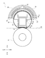
次に、定着装置13の構成について、図2~図4を参照しながら説明する。図2に示すように、定着装置13は、定着ベルト20と、加圧ローラー21(加圧部材)と、熱源22と、支持部材23と、パッド24(ニップ形成部材)と、摺動シート25と、ベルトガイド26と、電気部品ホルダー27とを備える。なお、図3では、説明の便宜上、支持部材23や摺動シート25を省略する。
定着ベルト20及び加圧ローラー21は、略箱型状の定着フレーム(図示せず)の内側で、搬送経路10を挟んで上側及び下側にそれぞれ配置され、互いに対向すると共に接触して配置される。定着フレームは、搬送経路10が用紙の搬送方向(左右方向)において定着フレームを貫通するように、プリンター本体2に取り付けられる。搬送経路10には、定着ベルト20及び加圧ローラー21の間に所定の加圧領域の定着ニップNが形成される。
なお、加圧領域とは、定着ベルト20と加圧ローラー21とが接触している領域であって、定着ベルト20及び加圧ローラー21による用紙への圧力が0Paである搬送方向上流側の位置から、その圧力が最大となる搬送方向の位置を経由して再びその圧力が0Paとなる搬送方向下流側の位置までの領域を示す。
定着ベルト20は、可撓性を有する無端状のベルトであり、用紙の搬送方向と直交(交差)する用紙の幅方向(前後方向)に長く、外径30mmの円筒状に形成される。定着ベルト20は、例えば、加熱層と、加熱層に周設される弾性層と、弾性層を被覆する離型層とから構成される。例えば、加熱層は、30~50μm程度の厚みのニッケル電鋳等の金属材料で形成され、弾性層は、200~500μm程度の厚みのシリコンゴム等の弾性材料で形成され、離型層は、PFA等のフッ素系樹脂材料で形成される。なお、定着ベルト20の内周面には、PTFE等の耐熱性樹脂コートが施される。
定着ベルト20は、前後方向を回転軸方向として、定着フレームに対して回転可能に取り付けられ、加圧ローラー21の回転に従動して回転する。定着ベルト20の下側(パッド24側)は、パッド24の形状に沿って成形される。定着ベルト20は、熱源22によって加熱され、例えば、定着ベルト20の加熱層が、熱源22が発生させる磁束によって誘導加熱されて、トナー像が形成された用紙に接触してトナー像を加熱する。
加圧ローラー21は、用紙の幅方向に長く、外径30mmの円柱状に形成される。加圧ローラー21は、例えば、円柱状の金属製の芯材と、芯材に周設された5mm程度の厚みのシリコンゴム等の樹脂製の弾性層とから構成され、弾性層はPFA等のフッ素系樹脂の離型層によって被覆される。
加圧ローラー21は、前後方向を回転軸方向として、定着フレームに対して回転可能に取り付けられる。例えば、加圧ローラー21の芯材が、モーター等の駆動源(図示せず)に接続され、駆動源から伝達される回転駆動力によって回転することで、加圧ローラー21が回転する。また、加圧ローラー21は、定着ベルト20側に加圧されて、定着ベルト20と加圧ローラー21との間に定着ニップNが形成され、定着ベルト20と共に、定着ニップNを通過する用紙を加圧する。加圧ローラー21は、例えば、300~400Nの加圧力を定着ベルト20に向けて作用するように構成される。
熱源22は、定着ベルト20の回転軸方向に長く、断面円弧状を有して定着ベルト20を覆うように形成され、定着ベルト20の外側(上側)に配置される。換言すれば、熱源22は、定着ベルト20を挟んで加圧ローラー21とは反対側で、定着ベルト20から所定間隔を空けて配置される。
熱源22は、一例として、定着ベルト20を誘導加熱(IH:Induction Heating)させるIHユニットである。IHユニットは、ボビン30と、コイル31と、センターコア32と、アーチコア33と、2列のサイドコア34とを備える。IHユニットは、コイル31に電流を流すことで磁束を生成し、この磁束を定着ベルト20に作用させることで定着ベルト20を誘導加熱(IH:Induction Heating)させる。IHユニットでは、制御装置15によって制御されて電源(図示せず)から電力が供給されることで、コイル31に電流が流れる。なお、制御装置15は、温度センサー(図示せず)によって検知された定着ベルト20の表面温度が所定の定着温度になるように、熱源22への電力供給を制御する。
ボビン30は、定着ベルト20の曲面(外周面上側)形状に沿った断面円弧状を有する板部材であり、定着ベルト20の上側に配置される。コイル31は、定着ベルト20の回転軸方向を往復しつつボビン30の外周面上に巻き回され、定着ベルト20の外周面に沿うように成形される。また、コイル31は、上記したように、電流を流すことで磁束を生成するIH用コイルである。
センターコア32、アーチコア33及び2列のサイドコア34は、コイル31で発生した磁束を定着ベルト20へと案内するフェライト部材を構成する。なお、ボビン30、センターコア32、アーチコア33及び2列のサイドコア34は、コイル31を収納するケースも兼ねる。
センターコア32は、角柱状に形成され、ボビン30の外周面上で左右方向の中央に配置される。アーチコア33は、ボビン30よりも外径が大きい断面円弧状を有する板部材であり、コイル31を挟んでボビン30の反対側に配置される。なお、ボビン30及びアーチコア33は、定着ベルト20と同軸となるように配置される。2列のサイドコア34は、板状に形成され、ボビン30及びアーチコア33の周方向の両端において、ボビン30とアーチコア33との間の隙間を塞ぐように配置される。
支持部材23は、例えば、金属材料によって、定着ベルト20よりも前後方向に長い角筒状に形成され、定着ベルト20の内側で略中央に配置される。支持部材23の前後方向の両端は、定着フレームに支持される。支持部材23は、定着ベルト20やその内側の部品を支持すると共に、加圧ローラー21からの加圧力を受けるために、機械的強度が強い材料及び形状で形成される。
パッド24は、例えば、LCP等の耐熱性樹脂によって、定着ベルト20の回転軸方向を長手方向とし、回転軸方向と直交(交差)するニップ幅方向を短手方向とする長形の部材であり、また、定着ニップNを大きくとるために短手方向にも延ばされる。パッド24は、定着ベルト20の内側において支持部材23よりも加圧ローラー21側(下側)で支持部材23に取り付けられる。
また、パッド24は、加圧ローラー21側(下側)の面、即ち、押圧面40が、摺動シート25を介して定着ベルト20の内周面に接触するように配置される。そして、パッド24は、定着ベルト20を介して加圧ローラー21からの加圧力を受け、この加圧力に対して定着ベルト20を介して加圧ローラー21を押圧する。これにより、パッド24は、加圧ローラー21と共に定着ベルト20を挟持して定着ベルト20及び加圧ローラー21の間に定着ニップNを形成する。
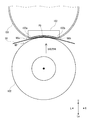
図3に示すように、本実施形態において、パッド24に対する加圧ローラー21の加圧方向は、加圧ローラー21の回転中心から定着ベルト20の回転中心へ向かう方向、即ち、上方である。また、パッド24に沿う定着ニップNが延びる方向(ニップ幅方向)は、加圧方向及び加圧ローラー21の回転軸方向と直交(交差)する方向、即ち、左右方向である。例えば、パッド24のニップ幅方向の中央が、加圧ローラー21の加圧方向に平行で加圧ローラー21の回転中心を通る延長線A上に位置するように、パッド24が配置される。なお、定着ニップNは、実際には、パッド24に沿って変形した定着ベルト20及び加圧ローラー21の接触領域がパッド24に沿って変形した形状になるので、左右方向に延びているが、左右方向と平行でなくてよい。
パッド24の加圧ローラー21側の押圧面40は、用紙の搬送方向の上流側(定着ニップNの入口側)の第1曲面41と下流側(定着ニップNの出口側)の第2曲面42とを有する。第1曲面41は、搬送方向の上流側に向かって加圧ローラー21側に湾曲した断面円弧状に形成され、第2曲面42は、搬送方向の下流側に向かって加圧ローラー21側に湾曲した円弧状に形成される。
第1曲面41及び第2曲面42は、上記した延長線Aの押圧面40上の交点付近に変曲点Bを設けて連続していて、パッド24は、上方に凹んだ断面形状を有する。換言すれば、パッド24の断面形状は、定着ニップNに対する押圧面40が複数の曲線で構成された複合曲線形状である。なお、第1曲面41及び第2曲面42の変曲点Bは、押圧面40と延長線Aとが交差する加圧中心に設けられてもよく、あるいは、延長線Aから用紙の搬送方向に±1mm程度の範囲内に設けられればよく、例えば、搬送方向の下流側に0.5mm程度ずらして設けることがニップ圧の分布や画質面から好ましい。
また、パッド24の押圧面40は、第1曲面41の第1曲率半径Ra(曲率半径)及び第2曲面42の第2曲率半径Rbが加圧ローラー21の半径Rpよりも大きく、第1曲面41の第1曲率半径Raが第2曲面42の第2曲率半径Rbよりも大きくなるように形成される。換言すれば、第2曲面42の円弧状を構成する中心点は、加圧ローラー21の中心点よりも下側に設けられ、第1曲面41の円弧状を構成する中心点は、第2曲面42の円弧状の中心点よりも下側に設けられることになる。
例えば、外径30mmの定着ベルト20及び外径30mmの加圧ローラー21に対して、第1曲面41は、80mm以上の第1曲率半径Raで形成され、第2曲面42は、40mm以上の第2曲率半径Rbで形成されるとよい。更に、パッド24の押圧面40は、第2曲面42の第2曲率半径Rbが加圧ローラー21の半径Rpの2倍よりも大きくなるように形成されるとよい。なお、本実施形態では、第1曲率半径Raが第2曲率半径Rbの2倍程度である例を説明するが、第1曲率半径Raは第2曲率半径Rbより僅かでも大きければよい。また、第1曲面41は、ニップ幅方向に平行な直線で形成されてもよく、この場合、第1曲面41の第1曲率半径Raは、無限大となる。
摺動シート25は、可撓性、耐熱性、摺動性、耐久性等を有する材料で形成され、支持部材23に取り付けられると共に、定着ベルト20の内周面とパッド24との間に介装される。摺動シート25は、パッド24の形状に沿って成形される。摺動シート25は、定着ベルト20の内周面と直接接触して、定着ベルト20とパッド24との摺動抵抗を低減し、定着ベルト20の摺動性能を確保する。摺動性を向上するために、摺動シート25には、オイル等の潤滑剤が塗布される。摺動シート25は、定着ベルト20とパッド24との磨耗も抑制する。
ベルトガイド26は、0.2~0.3mm程度の厚みの磁性SUS板等で、定着ベルト20の内周面の上側に沿う断面円弧状を有して形成される。ベルトガイド26は、円弧状の外周面が定着ベルト20の内周面に沿うように熱源22に対向する位置に配置され、支持部材23に取り付けられる。ベルトガイド26は、定着ベルト20の内周面に接触して、定着ベルト20の回転軌道を補助すると共に安定させる。また、ベルトガイド26は、定着ベルト20を透過した漏洩磁束を吸収して発熱を補助すると共に、定着ベルト20の内側への漏洩磁束を低減する。
電気部品ホルダー27は、定着ベルト20の内側に配置される温度センサー等の電気部品を取り付けるための部材であって、ベルトガイド26の内側で支持部材23に取り付けられる。
本実施形態によれば、上述のように、プリンター1(画像形成装置)の定着装置13は、熱源22によって加熱され、用紙に形成されたトナー像を加熱する回転可能な定着ベルト20と、定着ベルト20に対して加圧され、定着ベルト20との間を通過する用紙を加圧する回転可能な加圧ローラー21(加圧部材)と、定着ベルト20の内側に設けられ、加圧ローラー21と共に定着ベルト20を挟持して定着ベルト20及び加圧ローラー21の間に定着ニップNを形成するパッド24(ニップ形成部材)と、を備える。パッド24は、加圧ローラー21の加圧方向及び回転軸方向に交差するニップ幅方向に延びていて、パッド24の加圧ローラー21側の押圧面40は、用紙の搬送方向の上流側の第1曲面41と下流側の第2曲面42とを有する。第1曲面41は、搬送方向の上流側に向かって加圧ローラー21側に湾曲した円弧状に形成され、第2曲面42は、搬送方向の下流側に向かって加圧ローラー21側に湾曲した円弧状に形成される。第1曲面41及び第2曲面42は、加圧ローラー21の加圧方向に平行で加圧ローラー21の回転中心を通る延長線Aの、押圧面40上の交点付近に変曲点Bを設けて連続している。第1曲面41は、第2曲面42よりも大きい第1曲率半径Raで形成される。
定着装置13では、定着部材として定着ベルト20を採用しているので、熱容量を小さくしてウォームアップ時間を短縮することができる。また、パッド24が、ニップ幅方向に延びていて、パッド24の押圧面40は、加圧方向に凸型で、用紙の搬送方向の上流側及び下流側で加圧ローラー21側に湾曲して形成される。そのため、定着ニップNを大きく(ワイドに)形成することができ、定着ニップNから退出する用紙の定着ベルト20からの分離性を向上することができる。
更に、パッド24は、押圧面40の第1曲面41及び第2曲面42の変曲点Bを、加圧ローラー21の加圧中心付近に設けている。そのため、加圧ローラー21の加圧中心よりも上流側や下流側に変曲点Bが設けられて圧抜けが生じた場合に発生する不具合、例えば、圧抜けで用紙が微小スリップすることに起因する画像ずれ等の画質低下や、圧抜けで粒状のトナーが動くことに起因する微小な画像ずれを抑制することができる。
例えば、図4は、本実施形態の定着装置13によって用紙に定着処理を行った場合に、定着ニップNの加圧領域において、用紙の搬送方向の位置に応じて得られるニップ圧を示したグラフである。図4に示すように、加圧ローラー21の加圧中心付近では、加圧ローラー21によって用紙を定着ベルト20(パッド24)側に押し付ける荷重が掛かり易く、十分なニップ圧が得られるので、圧抜けの発生を抑制することができる。
また、パッド24の押圧面40において、第1曲面41は、第2曲面42よりも大きい第1曲率半径Raで形成される。そのため、用紙の定着装置13への搬送方向に対する、定着ニップNへの進入方向のずれを抑制し、用紙が定着ニップNに進入する際に定着ベルト20から受けるストレスを抑制することができ、進入時の用紙の挙動を安定化することができる。また、第1曲面41の第1曲率半径Raを大きくすることで、変曲点Bにおける用紙の定着ベルト20への接触性を向上し、圧抜けを更に抑制することができる。
更に、第1曲面41の第1曲率半径Raが比較的大きいため、厚紙等のコシの強い用紙が定着ニップNを通される場合、定着ニップNの入口付近と加圧中心との間でも、加圧ローラー21からの荷重を掛けて十分にニップ圧を得ることができ、圧抜けを抑制することができる。また、定着ニップNの出口付近と加圧中心との間では、第2曲面42の第2曲率半径Rbが比較的小さいが、搬送方向において上流側の第1曲面41の第1曲率半径Raが大きいので第2曲面42に対する用紙の進入角度が緩やかになり、用紙を第2曲面42に沿わせ易くなるため、コシの強い用紙が定着ニップNを通される場合でも、加圧ローラー21からの荷重を掛けてニップ圧を得ることができ、圧抜けを小さくすることができる。なお、定着ニップNの加圧中心よりも下流側では、トナーが加熱されて粒状から溶融されているので、ニップ圧が、加圧中心付近のピークの半分以上あれば、小さい圧抜けが生じても画像ずれを抑制することができる。
また、本実施形態の定着装置13では、パッド24は、第2曲面42の第2曲率半径Rbが加圧ローラー21の半径Rpの2倍よりも大きく構成されるとよい。これにより、変曲点Bや第2曲面42での圧抜けを更に抑制することができ、定着ニップNから退出する用紙の定着ベルト20からの分離性を更に向上することができる。
なお、上記した実施形態では、熱源22がIHユニットで構成されて定着ベルト20の外部に設けられる例を説明したが、本発明は、この例に限定されず、例えば、他の実施形態では、熱源22は、ハロゲンヒーターやセラミックヒーター等によって構成されて定着ベルト20の外部又は内部に設けられてもよい。
本実施形態では、モノクロのプリンター1に本発明の構成を適用する場合について説明したが、他の異なる実施形態では、カラープリンター、複写機、ファクシミリ、複合機等の他の画像形成装置に本発明の構成を適用することも可能である。
なお、上記実施形態の説明は、本発明に係る定着装置および画像形成装置における一態様を示すものであって、本発明の技術範囲は、上記実施形態に限定されるものではない。
Claims (7)
- 熱源によって加熱され、用紙に形成されたトナー像を加熱する回転可能な定着ベルトと、
前記定着ベルトに対して加圧され、前記定着ベルトとの間を通過する前記用紙を加圧する回転可能な加圧部材と、
前記定着ベルトの内側に設けられ、前記加圧部材と共に前記定着ベルトを挟持して前記定着ベルト及び前記加圧部材の間に定着ニップを形成するニップ形成部材と、を備え、
前記ニップ形成部材は、前記加圧部材の加圧方向及び回転軸方向に交差するニップ幅方向に延びていて、前記ニップ形成部材の前記加圧部材の側の押圧面は、前記用紙の搬送方向の上流側の第1曲面と下流側の第2曲面とを有し、
前記第1曲面は、前記搬送方向の上流側に向かって前記加圧部材の側に湾曲した円弧状に形成され、前記第2曲面は、前記搬送方向の下流側に向かって前記加圧部材の側に湾曲した円弧状に形成され、
前記第1曲面及び前記第2曲面は、前記加圧方向に平行で前記加圧部材の回転中心を通る延長線の、前記押圧面上の交点付近に変曲点を設けて連続し、
前記第1曲面は、前記第2曲面よりも大きい曲率半径で形成される定着装置。
- 前記ニップ形成部材は、前記第2曲面の曲率半径が前記加圧部材の半径の2倍よりも大きく構成される請求項1に記載の定着装置。
- 前記第1曲面及び前記第2曲面の前記変曲点は、前記押圧面と前記延長線とが交差する加圧中心に設けられる請求項1に記載の定着装置。
- 前記第1曲面及び前記第2曲面の前記変曲点は、前記押圧面と前記延長線とが交差する加圧中心から前記搬送方向の下流側にずらして設けられる請求項1に記載の定着装置。
- 前記第1曲面の第1曲率半径が前記第2曲面の第2曲率半径の2倍程度である請求項1に記載の定着装置。
- 前記第1曲面は、前記ニップ幅方向に平行な直線で形成され、前記第1曲面の第1曲率半径は無限大となる請求項1に記載の定着装置。
- 請求項1に記載の定着装置を備えている画像形成装置。
Priority Applications (2)
| Application Number | Priority Date | Filing Date | Title |
|---|---|---|---|
| US17/262,089 US11366415B2 (en) | 2018-07-25 | 2019-06-26 | Fixing device and image forming apparatus |
| JP2020532233A JP7070682B2 (ja) | 2018-07-25 | 2019-06-26 | 定着装置および画像形成装置 |
Applications Claiming Priority (2)
| Application Number | Priority Date | Filing Date | Title |
|---|---|---|---|
| JP2018139444 | 2018-07-25 | ||
| JP2018-139444 | 2018-07-25 |
Publications (1)
| Publication Number | Publication Date |
|---|---|
| WO2020021946A1 true WO2020021946A1 (ja) | 2020-01-30 |
Family
ID=69180990
Family Applications (1)
| Application Number | Title | Priority Date | Filing Date |
|---|---|---|---|
| PCT/JP2019/025373 Ceased WO2020021946A1 (ja) | 2018-07-25 | 2019-06-26 | 定着装置および画像形成装置 |
Country Status (3)
| Country | Link |
|---|---|
| US (1) | US11366415B2 (ja) |
| JP (1) | JP7070682B2 (ja) |
| WO (1) | WO2020021946A1 (ja) |
Citations (3)
| Publication number | Priority date | Publication date | Assignee | Title |
|---|---|---|---|---|
| JP2013156399A (ja) * | 2012-01-30 | 2013-08-15 | Kyocera Document Solutions Inc | 定着装置及びそれを備えた画像形成装置 |
| US20160357134A1 (en) * | 2015-06-03 | 2016-12-08 | Kabushiki Kaisha Toshiba | Image forming apparatus that controls an image forming section and a fixing device |
| JP2017151465A (ja) * | 2017-05-01 | 2017-08-31 | 株式会社リコー | 定着装置および画像形成装置 |
Family Cites Families (3)
| Publication number | Priority date | Publication date | Assignee | Title |
|---|---|---|---|---|
| JP6069950B2 (ja) | 2012-08-21 | 2017-02-01 | 株式会社リコー | 定着装置および画像形成装置 |
| JP6270106B2 (ja) | 2013-09-30 | 2018-01-31 | ブラザー工業株式会社 | 定着装置 |
| JP2016142987A (ja) * | 2015-02-04 | 2016-08-08 | 株式会社リコー | 定着装置及び画像形成装置 |
-
2019
- 2019-06-26 US US17/262,089 patent/US11366415B2/en active Active
- 2019-06-26 JP JP2020532233A patent/JP7070682B2/ja active Active
- 2019-06-26 WO PCT/JP2019/025373 patent/WO2020021946A1/ja not_active Ceased
Patent Citations (3)
| Publication number | Priority date | Publication date | Assignee | Title |
|---|---|---|---|---|
| JP2013156399A (ja) * | 2012-01-30 | 2013-08-15 | Kyocera Document Solutions Inc | 定着装置及びそれを備えた画像形成装置 |
| US20160357134A1 (en) * | 2015-06-03 | 2016-12-08 | Kabushiki Kaisha Toshiba | Image forming apparatus that controls an image forming section and a fixing device |
| JP2017151465A (ja) * | 2017-05-01 | 2017-08-31 | 株式会社リコー | 定着装置および画像形成装置 |
Also Published As
| Publication number | Publication date |
|---|---|
| JP7070682B2 (ja) | 2022-05-18 |
| US20210294252A1 (en) | 2021-09-23 |
| US11366415B2 (en) | 2022-06-21 |
| JPWO2020021946A1 (ja) | 2021-08-02 |
Similar Documents
| Publication | Publication Date | Title |
|---|---|---|
| JP5582655B2 (ja) | 定着装置及びそれを備えた画像形成装置 | |
| US10001736B2 (en) | Fixing device and image forming apparatus | |
| US9026023B2 (en) | Fixing device and image forming apparatus having the same | |
| JP2012008377A (ja) | 画像加熱装置 | |
| JP4673050B2 (ja) | 定着装置および画像形成装置 | |
| JP6828616B2 (ja) | 定着装置及び画像形成装置 | |
| JP5618975B2 (ja) | 定着装置及びそれを備えた画像形成装置 | |
| JP7070682B2 (ja) | 定着装置および画像形成装置 | |
| JP6314901B2 (ja) | 定着装置及び画像形成装置 | |
| US9164446B2 (en) | Fixing device and image forming apparatus | |
| US9588469B2 (en) | Fixing device and image forming apparatus | |
| CN110837217B (zh) | 定影装置和图像形成装置 | |
| JP7596125B2 (ja) | 画像形成装置、定着器 | |
| US10642200B2 (en) | Fixing device with tiltable spacer between heater and safety | |
| JP7139935B2 (ja) | 定着装置及び画像形成装置 | |
| JP2004234951A (ja) | 加熱装置 | |
| JP2019020482A (ja) | 定着装置及び画像形成装置 | |
| JP5698919B2 (ja) | 定着装置及びこれを搭載した画像形成装置 | |
| JP6118742B2 (ja) | 定着装置及び画像形成装置 | |
| JP6573393B2 (ja) | 画像形成装置 | |
| JP2007240623A (ja) | 画像加熱装置 | |
| JP2020194134A (ja) | 定着装置及び画像形成装置 | |
| US20160170349A1 (en) | Fixing device and image forming apparatus | |
| JP2020067621A (ja) | 定着装置及び画像形成装置 | |
| JP2019203995A (ja) | 定着装置および定着部材 |
Legal Events
| Date | Code | Title | Description |
|---|---|---|---|
| 121 | Ep: the epo has been informed by wipo that ep was designated in this application |
Ref document number: 19841503 Country of ref document: EP Kind code of ref document: A1 |
|
| ENP | Entry into the national phase |
Ref document number: 2020532233 Country of ref document: JP Kind code of ref document: A |
|
| NENP | Non-entry into the national phase |
Ref country code: DE |
|
| 122 | Ep: pct application non-entry in european phase |
Ref document number: 19841503 Country of ref document: EP Kind code of ref document: A1 |