WO2020021785A1 - ガス検出装置、ガス検出方法、表示制御方法、およびプログラム - Google Patents
ガス検出装置、ガス検出方法、表示制御方法、およびプログラム Download PDFInfo
- Publication number
- WO2020021785A1 WO2020021785A1 PCT/JP2019/015889 JP2019015889W WO2020021785A1 WO 2020021785 A1 WO2020021785 A1 WO 2020021785A1 JP 2019015889 W JP2019015889 W JP 2019015889W WO 2020021785 A1 WO2020021785 A1 WO 2020021785A1
- Authority
- WO
- WIPO (PCT)
- Prior art keywords
- unit
- image
- input
- display
- information
- Prior art date
- Legal status (The legal status is an assumption and is not a legal conclusion. Google has not performed a legal analysis and makes no representation as to the accuracy of the status listed.)
- Ceased
Links
Images







Classifications
-
- H—ELECTRICITY
- H04—ELECTRIC COMMUNICATION TECHNIQUE
- H04N—PICTORIAL COMMUNICATION, e.g. TELEVISION
- H04N5/00—Details of television systems
- H04N5/76—Television signal recording
- H04N5/765—Interface circuits between an apparatus for recording and another apparatus
- H04N5/77—Interface circuits between an apparatus for recording and another apparatus between a recording apparatus and a television camera
-
- G—PHYSICS
- G06—COMPUTING OR CALCULATING; COUNTING
- G06T—IMAGE DATA PROCESSING OR GENERATION, IN GENERAL
- G06T7/00—Image analysis
- G06T7/0002—Inspection of images, e.g. flaw detection
-
- G—PHYSICS
- G01—MEASURING; TESTING
- G01M—TESTING STATIC OR DYNAMIC BALANCE OF MACHINES OR STRUCTURES; TESTING OF STRUCTURES OR APPARATUS, NOT OTHERWISE PROVIDED FOR
- G01M3/00—Investigating fluid-tightness of structures
- G01M3/02—Investigating fluid-tightness of structures by using fluid or vacuum
-
- G—PHYSICS
- G01—MEASURING; TESTING
- G01M—TESTING STATIC OR DYNAMIC BALANCE OF MACHINES OR STRUCTURES; TESTING OF STRUCTURES OR APPARATUS, NOT OTHERWISE PROVIDED FOR
- G01M3/00—Investigating fluid-tightness of structures
- G01M3/38—Investigating fluid-tightness of structures by using light
-
- G—PHYSICS
- G06—COMPUTING OR CALCULATING; COUNTING
- G06F—ELECTRIC DIGITAL DATA PROCESSING
- G06F3/00—Input arrangements for transferring data to be processed into a form capable of being handled by the computer; Output arrangements for transferring data from processing unit to output unit, e.g. interface arrangements
- G06F3/01—Input arrangements or combined input and output arrangements for interaction between user and computer
- G06F3/048—Interaction techniques based on graphical user interfaces [GUI]
- G06F3/0481—Interaction techniques based on graphical user interfaces [GUI] based on specific properties of the displayed interaction object or a metaphor-based environment, e.g. interaction with desktop elements like windows or icons, or assisted by a cursor's changing behaviour or appearance
- G06F3/0482—Interaction with lists of selectable items, e.g. menus
-
- G—PHYSICS
- G06—COMPUTING OR CALCULATING; COUNTING
- G06F—ELECTRIC DIGITAL DATA PROCESSING
- G06F3/00—Input arrangements for transferring data to be processed into a form capable of being handled by the computer; Output arrangements for transferring data from processing unit to output unit, e.g. interface arrangements
- G06F3/01—Input arrangements or combined input and output arrangements for interaction between user and computer
- G06F3/048—Interaction techniques based on graphical user interfaces [GUI]
- G06F3/0484—Interaction techniques based on graphical user interfaces [GUI] for the control of specific functions or operations, e.g. selecting or manipulating an object, an image or a displayed text element, setting a parameter value or selecting a range
- G06F3/04847—Interaction techniques to control parameter settings, e.g. interaction with sliders or dials
-
- G—PHYSICS
- G06—COMPUTING OR CALCULATING; COUNTING
- G06T—IMAGE DATA PROCESSING OR GENERATION, IN GENERAL
- G06T11/00—Two-dimensional [2D] image generation
-
- G—PHYSICS
- G06—COMPUTING OR CALCULATING; COUNTING
- G06T—IMAGE DATA PROCESSING OR GENERATION, IN GENERAL
- G06T11/00—Two-dimensional [2D] image generation
- G06T11/10—Texturing; Colouring; Generation of textures or colours
-
- G—PHYSICS
- G06—COMPUTING OR CALCULATING; COUNTING
- G06T—IMAGE DATA PROCESSING OR GENERATION, IN GENERAL
- G06T11/00—Two-dimensional [2D] image generation
- G06T11/20—Drawing from basic elements
- G06T11/26—Drawing of charts or graphs
-
- G—PHYSICS
- G06—COMPUTING OR CALCULATING; COUNTING
- G06T—IMAGE DATA PROCESSING OR GENERATION, IN GENERAL
- G06T7/00—Image analysis
- G06T7/0002—Inspection of images, e.g. flaw detection
- G06T7/0004—Industrial image inspection
-
- G—PHYSICS
- G11—INFORMATION STORAGE
- G11B—INFORMATION STORAGE BASED ON RELATIVE MOVEMENT BETWEEN RECORD CARRIER AND TRANSDUCER
- G11B27/00—Editing; Indexing; Addressing; Timing or synchronising; Monitoring; Measuring tape travel
- G11B27/10—Indexing; Addressing; Timing or synchronising; Measuring tape travel
- G11B27/11—Indexing; Addressing; Timing or synchronising; Measuring tape travel by using information not detectable on the record carrier
-
- G—PHYSICS
- G11—INFORMATION STORAGE
- G11B—INFORMATION STORAGE BASED ON RELATIVE MOVEMENT BETWEEN RECORD CARRIER AND TRANSDUCER
- G11B27/00—Editing; Indexing; Addressing; Timing or synchronising; Monitoring; Measuring tape travel
- G11B27/10—Indexing; Addressing; Timing or synchronising; Measuring tape travel
- G11B27/19—Indexing; Addressing; Timing or synchronising; Measuring tape travel by using information detectable on the record carrier
- G11B27/28—Indexing; Addressing; Timing or synchronising; Measuring tape travel by using information detectable on the record carrier by using information signals recorded by the same method as the main recording
-
- H—ELECTRICITY
- H04—ELECTRIC COMMUNICATION TECHNIQUE
- H04N—PICTORIAL COMMUNICATION, e.g. TELEVISION
- H04N5/00—Details of television systems
- H04N5/76—Television signal recording
- H04N5/91—Television signal processing therefor
- H04N5/92—Transformation of the television signal for recording, e.g. modulation, frequency changing; Inverse transformation for playback
- H04N5/9201—Transformation of the television signal for recording, e.g. modulation, frequency changing; Inverse transformation for playback involving the multiplexing of an additional signal and the video signal
- H04N5/9206—Transformation of the television signal for recording, e.g. modulation, frequency changing; Inverse transformation for playback involving the multiplexing of an additional signal and the video signal the additional signal being a character code signal
-
- H—ELECTRICITY
- H04—ELECTRIC COMMUNICATION TECHNIQUE
- H04N—PICTORIAL COMMUNICATION, e.g. TELEVISION
- H04N9/00—Details of colour television systems
- H04N9/79—Processing of colour television signals in connection with recording
- H04N9/80—Transformation of the television signal for recording, e.g. modulation, frequency changing; Inverse transformation for playback
- H04N9/82—Transformation of the television signal for recording, e.g. modulation, frequency changing; Inverse transformation for playback the individual colour picture signal components being recorded simultaneously only
- H04N9/8205—Transformation of the television signal for recording, e.g. modulation, frequency changing; Inverse transformation for playback the individual colour picture signal components being recorded simultaneously only involving the multiplexing of an additional signal and the colour video signal
-
- G—PHYSICS
- G06—COMPUTING OR CALCULATING; COUNTING
- G06T—IMAGE DATA PROCESSING OR GENERATION, IN GENERAL
- G06T2200/00—Indexing scheme for image data processing or generation, in general
- G06T2200/24—Indexing scheme for image data processing or generation, in general involving graphical user interfaces [GUIs]
-
- G—PHYSICS
- G06—COMPUTING OR CALCULATING; COUNTING
- G06T—IMAGE DATA PROCESSING OR GENERATION, IN GENERAL
- G06T2207/00—Indexing scheme for image analysis or image enhancement
- G06T2207/10—Image acquisition modality
- G06T2207/10024—Color image
-
- G—PHYSICS
- G06—COMPUTING OR CALCULATING; COUNTING
- G06T—IMAGE DATA PROCESSING OR GENERATION, IN GENERAL
- G06T2207/00—Indexing scheme for image analysis or image enhancement
- G06T2207/10—Image acquisition modality
- G06T2207/10048—Infrared image
Definitions
- the present invention relates to a gas detection device, a gas detection method, a display control method, and a program.
- Patent Document 1 Japanese Patent Document 1
- Patent Literature 1 discloses an infrared camera and a visible light camera for capturing an image (moving image) of an inspection area including an inspection target, an image processing unit for processing infrared image data captured by the infrared camera, and a display. And a gas leak detection device having the same.
- the image processing unit extracts an image of fluctuation caused by gas leakage from the image data of the inspection area.
- the display unit displays an inspection image in which the fluctuation image data is superimposed on the image data of the inspection area captured by the visible light camera.
- the inspector visually and easily identifies the location of the gas leak in the inspection area by visually checking the inspection image displayed on the display unit. it can.
- the importance of the image differs between the normal image of the inspection target and the emergency image in which gas leakage occurs in the inspection target.
- inspection images may require images of a predetermined time including a normal image and an emergency image, for example, a specific image (for example, only an emergency image) is required. In some cases. If the user can add supplementary information to a specific image in the inspection image, the specific image can be efficiently extracted from the inspection image.
- the gas detection device disclosed in Patent Document 1 does not have such a configuration.
- An object of the present invention is to provide a gas detection device, a gas detection method, a display control method, and a program that can add supplementary information to a specific image in an inspection image.
- One aspect of the gas detection device is an image processing unit that performs image processing on infrared image data of an inspection area imaged by an imaging unit to visualize gas, and an inspection image that reflects the result of the image processing.
- the display device includes a display processing unit to be displayed on the display unit, and an input unit to receive input of supplementary information on the inspection image displayed on the display unit.
- One aspect of the gas detection device is an image processing unit that performs image processing on infrared image data of an inspection region imaged by an imaging unit to visualize the gas, and detects the gas based on a result of the image processing.
- One aspect of the gas detection method according to the present invention is a gas detection method executed in a gas detection device, in which the gas is visualized by performing image processing on infrared image data of an inspection region captured by an imaging unit, The inspection image reflecting the result of the image processing is displayed on the display unit, and input of supplementary information on the inspection image displayed on the display unit is received.
- One aspect of the program according to the present invention is to provide a computer of a gas detection device that displays an inspection image in which a gas is visualized on a display unit, by performing image processing on infrared image data of an inspection region imaged by an imaging unit and extracting the gas.
- a process of visualizing, a process of displaying an inspection image reflecting the result of the image processing on the display unit, and a process of receiving input of supplementary information on the inspection image displayed on the display unit are executed.
- a gas detection device it is possible to provide a gas detection device, a gas detection method, a display control method, and a program that can add supplementary information to a specific image in an inspection image.
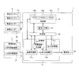
- FIG. 1 is a block diagram illustrating a configuration example of a gas detection device according to an embodiment of the present invention.
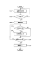
- FIG. 2 is a flowchart for explaining a flow when supplementary information is input during imaging.
- FIG. 3 is a flowchart for explaining a flow when inputting supplementary information during reproduction.
- FIG. 4 is a flowchart for explaining a flow when generating and outputting output information.
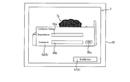
- FIG. 5A is a diagram illustrating an example of an inspection image displayed on a display unit during imaging.
- FIG. 5B is a diagram illustrating an example of the inspection image of the display unit changed from the state illustrated in FIG. 5A.
- FIG. 6A is a diagram illustrating a first modification of the second input screen.
- FIG. 5A is a diagram illustrating an example of an inspection image displayed on a display unit during imaging.
- FIG. 5B is a diagram illustrating an example of the inspection image of the display unit changed from the state illustrated in FIG. 5A.
- FIG. 6A is
- FIG. 6B is a diagram illustrating a first modification of the second input screen in a state different from that of FIG. 6A.
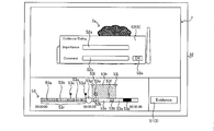
- FIG. 7A is a diagram illustrating an example of an inspection image displayed on the display unit during reproduction.
- FIG. 7B is a diagram illustrating an example of the inspection image of the display unit changed from the state illustrated in FIG. 7A.
- FIG. 8 is a block diagram illustrating a configuration example of a gas detection device according to another embodiment of the present invention.
- FIG. 9A is a diagram illustrating an example of an inspection image displayed on a display unit during imaging.
- FIG. 9B is a diagram illustrating an example of the inspection image of the display unit changed from the state illustrated in FIG. 9A.
- FIG. 10A is a diagram illustrating a modification of the second input image.
- FIG. 10A is a diagram illustrating a modification of the second input image.
- FIG. 10B is a diagram illustrating a modified example of the second input image in a state different from FIG. 10A.
- FIG. 11A is a diagram illustrating an example of an inspection image displayed on the display unit during reproduction.
- FIG. 11B is a diagram illustrating an example of the inspection image of the display unit changed from the state illustrated in FIG. 11A.
- FIG. 12 is a flowchart illustrating an example of the operation of the gas detection device.
- FIG. 1 is a block diagram of the gas detection device 1.
- the gas detection device 1 captures, for example, an inspection area including an inspection target (a plant or the like) in a gas field, and generates infrared image data of the inspection area. Then, the gas detection device 1 performs image processing on the infrared image data to generate an inspection image in which the gas is visualized. Further, in the case of the gas detection device 1 according to the present embodiment, the user can add supplementary information to the inspection image at an arbitrary timing while visually recognizing the inspection image displayed on the display unit. In the following description, images include not only still images but also moving images.
- the gas detection device 1 includes an imaging device 2 and a gas detection device main body 3.
- the imaging device 2 and the gas detection device main body 3 are connected via a cable 4.
- the imaging device 2 may be connected to the gas detection device main body 3 via wireless communication.
- the imaging device 2 may be connected to the gas detection device main body 3 via a network such as the Internet.
- the imaging device 2 is, for example, a portable camera device. Note that the imaging device 2 may be a camera device fixed at a predetermined position. The imaging device 2 may be controlled by, for example, a control unit 35 of the gas detection device main body 3 described later, a control unit (not shown) included in the imaging device 2, and the like.
- the imaging device 2 starts imaging, for example, when an instruction to start imaging (hereinafter, referred to as “imaging start instruction”) is input from the user via the operation input unit 33 of the gas detection device main body 3.
- imaging start instruction an instruction to start imaging
- the imaging device 2 does not need to start imaging if imaging information described below has not been input by the user.
- the imaging device 2 includes a visible light imaging unit 21 and an infrared imaging unit 22.
- the visible light imaging unit 21 includes a first optical system (not shown), a first optical filter (not shown), a visible light sensor (not shown), and the like.
- the first optical system forms an image of visible light incident from the inspection area serving as a subject on the visible light sensor.
- the first optical filter is an infrared cut filter or the like, which is arranged on the optical path connecting the optical system and the visible light sensor.
- the infrared cut filter cuts infrared rays from light that has passed through the optical system.
- the visible light sensor is, for example, a CMOS image sensor and receives visible light of black and white BW or visible light of color RGB to generate visible image data.
- Such a visible light imaging unit 21 captures, for example, an inspection area including an inspection target of a gas field (for example, the plant 6a in FIG. 5A), and processes the visible image data into a processing unit 31 (specifically, an image processing unit). 31a).
- the visible image data generated by the visible light imaging unit 21 is a still image or a moving image.
- the inspection image 7 (see FIG. 5A) displayed on the display unit 32 described later is infrared image data described later, the visible light imaging unit 21 may be omitted.
- the infrared imaging unit 22 includes a second optical system (not shown), a second optical filter (not shown), an infrared sensor (not shown), and the like.
- the second optical system forms an infrared ray incident from the inspection area, which is the subject, on the infrared sensor.
- the second optical filter is a bandpass filter or the like disposed on the optical path connecting the second optical system and the infrared sensor.
- the second optical filter passes only infrared light included in a predetermined wavelength band among infrared light that has passed through the optical system.
- the pass wavelength band of the second optical filter is substantially set to the absorption wavelength band of the gas to be detected. For example, when the pass wavelength band is set to a middle wavelength range of 3.2 to 3.4 ⁇ m, methane gas and the like can be detected.
- the infrared sensor is, for example, a quantum-type indium antimony (INSb) image sensor, a thermal-type thermopile array sensor, a microbolometer, or the like, and receives infrared rays to generate infrared image data.
- the infrared imaging unit 22 captures an image of the inspection area in synchronization with the visible light imaging unit 21 and sequentially outputs infrared image data to the processing unit 31 (specifically, the image processing unit 31a).
- the infrared image data generated by the infrared imaging unit 22 is a still image or a moving image. Such infrared image data indicates the temperature distribution of the inspection area.
- the gas detection device main body 3 uses the information received from the imaging device 2 to visualize the gas generated in the inspection area.
- a gas detection device main body 3 is a mobile terminal such as a tablet terminal, a smartphone, a laptop terminal, or a wearable terminal, which is communicatively connected to the imaging device 2.
- the gas detection device main body 3 includes a processing unit 31, a display unit 32, an operation input unit 33, a storage unit 34, a control unit 35, and the like.
- the processing unit 31 includes at least one dedicated hardware (electronic circuit) corresponding to each processing, such as a DSP (Digital Signal Processor), an ASIC (Application Specific Integrated Circuit), or a PLD (Programmable Logic Device).
- the processing unit 31 has, as functional blocks, an image processing unit 31a, a display processing unit 31b, an output processing unit 31c, and the like. Each function of the processing unit 31 described later is realized under the control of the control unit 35.
- Image processing unit 31a ⁇ Image processing unit>
- the function of the image processing unit 31a is realized under the control of the control unit 35.
- the image processing unit 31a receives the infrared image data of the inspection area (hereinafter, referred to as “infrared image data before image processing”) from the infrared imaging unit 22. Then, the image processing unit 31a performs predetermined image processing on the infrared image data of the inspection area, detects a portion where gas is present in the infrared image data, and visualizes the detected portion (hereinafter, “gas”). Visualization processing ”). The image processing unit 31a assigns a specific color (such as red) to a portion where gas exists in the infrared image data before the image processing.
- the infrared image data that has been subjected to the gas visualization processing is referred to as image-processed infrared image data.
- a method for detecting gas from infrared image data of an inspection area will be briefly described.
- a temperature change that is, a change in luminance in the infrared image data of the inspection area
- the image processing unit 31a detects a portion where gas exists based on such a temperature change. Since the gas detection method is a known image processing method, a detailed description is omitted.
- the image processing unit 31a receives visible image data (hereinafter, referred to as “visible image data before image processing”) from the visible light imaging unit 21. Then, the image processing unit 31a generates inspection image data in which the visible image data before the image processing is combined with the infrared image data after the image processing.
- the inspection image data is displayed on the display unit as the inspection image 7 (see FIG. 5A).
- the gas image 7a (see FIG. 5A) corresponding to the gas in the inspection image 7 is given the specific color. Note that the infrared image data after the image processing described above may be used as inspection image data without being combined with visible image data.
- the image processing unit 31a outputs the inspection image data to the display processing unit 31b.
- the image processing unit 31a outputs the inspection image data to the storage unit 34. Further, the image processing section 31a may output the infrared image data after the image processing to the storage section 34. The image processing unit 31a may output the visible image data before the image processing to the storage unit 34.
- ⁇ Display processing unit> the function of the display processing unit 31b will be described.
- the function of the display processing unit 31b is realized under the control of the control unit 35.
- Such a display processing unit 31b controls display on a display unit 32 described later.
- the display processing unit 31b causes the display unit 32 to display an imaging information input image (not shown) for inputting imaging information.
- the image data serving as the basis of the imaging information input image is stored in the storage unit 34 in advance.
- the display processing unit 31b converts the inspection image data received from the image processing unit 31a into a display signal corresponding to the display unit 32 and outputs the display signal, and causes the display unit 32 to display the inspection image 7 (see FIG. 5A).
- the display processing unit 31b causes the display unit 32 to display the supplementary information input image 5 (see FIG. 5A) for inputting the supplementary information together with the inspection image 7.
- FIG. 5A is a diagram showing an example of the inspection image 7 and the supplementary information input image 5 displayed on the display unit 32.
- the supplementary information input image 5 is, for example, an icon.
- the image data serving as the basis of the supplementary information input image 5 is stored in the storage unit 34 in advance.
- the supplementary information input image 5 may be composed of, for example, a plurality of images that are gradually displayed in a pop-up manner by a user's touch operation.
- the supplementary information input image 5 includes a first input image 51 (see FIG. 5A) that is always displayed on the display unit 32 together with the inspection image 7, and a user operates the first input image 51 (for example, touches 2), and a second input image 52 (see FIG. 5B) displayed on the display unit 32 when the operation is performed.
- the display processing unit 31b causes the display unit 32 to display the second input image 52 when the user operates the first input image 51.
- the display processing unit 31b deletes the second input image 52 from the display unit 32.
- the display processing unit 31b may delete the second input image 52 after a predetermined period of time has elapsed since the display of the second input image 52. That is, the screen displayed as a pop-up, such as the second input image 52, may automatically disappear after a predetermined time has elapsed since the display.
- the display processing unit 31b converts the inspection image data stored in the storage unit 34 into a display unit when a reproduction start instruction (hereinafter, referred to as a “reproduction start instruction”) is input via the operation input unit 33.
- the inspection image 7 is displayed on the display unit 32 after being converted into a display signal corresponding to 32 and output.
- the display processing unit 31b causes the display unit 32 to display the supplementary information input image 5 together with the inspection image 7.
- the display processing unit 31b causes the display unit 32 to display a seek bar image 53 (see FIGS. 7A and 7B).
- Image data serving as the basis of the seek bar image 53 is stored in the storage unit 34 in advance. The user can check the reproduction status of the inspection image data by using the seek bar image 53. Further, the user can adjust the reproduction position of the inspection image data by operating the seek bar image 53.
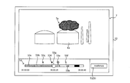
- the seek bar image 53 will be described with reference to FIG. 7A.
- a first bar element 53a (a portion with a diagonal grid) means a portion that has already been reproduced in the inspection image data.
- the second bar element 53b (hatched portion) means, for example, a portion where the occurrence of gas leakage is mechanically detected based on the detection result of the image processing unit 31a. .
- the first mark 53c indicates a portion checked by the user.
- the second mark 53d indicates unnecessary image data.
- the third mark 53e and the fourth mark 53f indicate portions where supplementary information is added by the user.
- the third mark 53e means supplementary information (evidence) closest to the reproduction position mark 53g indicating the reproduction position.
- a white portion means an unreproduced portion.
- a black portion indicates a portion from which data has been deleted.
- the output processing unit 31c generates output information including imaging information and inspection image data under the control of the control unit 35.
- the output processing unit 31c generates output information when an output instruction is input from the operation input unit 33.
- the output processing unit 31c extracts the inspection image data in the range and generates the extracted information as output information.
- the output information may include, for example, inspection image data associated with the supplementary information.
- the output processing unit 31c outputs the output information to an output device such as a printer, for example.
- the output device may be connected to the gas detection device main body 3 by wire or wirelessly.
- the output device may be connected to the gas detection device main body 3 via a network such as the Internet.
- the output processing unit 31c may output the output information to a portable storage medium such as an optical disk, a magneto-optical disk, and a memory card.
- the output processing unit 31c may output the output information to the server.
- the display unit 32 is, for example, a display of a portable terminal included in the gas detection device main body 3.
- a liquid crystal display, an organic EL display, or the like can be used.
- the display is a flat panel display with a touch panel.
- the display unit 32 displays various images under the control of the control unit 35 based on a display signal from the display processing unit 31b.
- the display unit 32 includes an inspection image 7 for the user to detect gas by visual recognition, an auxiliary information input image 5 for the user to input additional information, and a seek bar for the user to check the reproduction status of the inspection image data.
- the image 53 and the like are displayed (see FIGS. 5A to 7A).
- the operation input unit 33 is an input unit and receives, for example, an input of imaging information and an input of supplementary information. In addition, the operation input unit 33 receives an operation related to reproduction of inspection image data and an operation related to imaging of the imaging device 2. Note that the imaging information includes various information necessary for starting imaging by the imaging device 2. The imaging information will be described later.
- the operation input unit 33 receives an output instruction.
- the operation input unit 33 may receive, for example, designation of an item included in the output information together with the output instruction.
- the items of the output information include imaging information described later and other arbitrary information (for example, climate information at the time of imaging).
- the operation input unit 33 may receive designation of a range of inspection image data to be output as output information.
- the user specifies, for example, a range of inspection image data to be output from the seek bar image 53 (see FIG. 7A) displayed on the display unit 32.
- the operation input unit 33 may allow the input of the output instruction only when the imaging information corresponding to the examination region to be imaged is input (when the imaging information is not stored in the storage unit 34). .
- the operation input unit 33 receives the input of the output instruction. It may be prohibited.
- the operation input unit 33 permits the input of the output instruction only when the supplementary information associated with the inspection image data is input (when the supplementary information is not stored in the storage unit 34). You may.
- the operation input unit 33 receives the input of the output instruction. May be prohibited.
- the operation input unit 33 may allow the input of the output instruction only when the imaging information corresponding to the inspection area and the supplementary information corresponding to the inspection image data are input.
- the operation input unit 33 is configured by a flat panel display with a touch panel provided integrally with the display unit 32. Through the operation input unit 33, the user can perform input of imaging information, input of supplementary information, operation of the imaging device 2, and reproduction of inspection image data.
- the operation input unit 33 is not limited to a flat panel display with a touch panel, but may be an input device such as a keyboard, a mouse, or a microphone.
- the control unit 35 includes a CPU 35a (Central Processing Unit) as an arithmetic / control device, a RAM 35b (Random Access Memory), and a ROM 35c (Read Only Memory) as a main storage device.
- the ROM 35c stores basic programs and basic setting data.
- the CPU 35a reads out a program corresponding to the processing content from the ROM 35c or the storage unit 34, develops the program on the RAM 35b, and executes the developed program to centrally control the operation of each block of the gas detection device 1.
- the control unit 35 controls the entire gas detection device 1 by controlling the imaging device 2, the display unit 32, the operation input unit 33, and the storage unit 34 according to their respective functions.
- each functional block is realized by the cooperation of the hardware constituting each functional block and the control unit 35. Note that a part or all of the functions of each functional block may be realized by the control unit 35 executing the program.
- the storage unit 34 is, for example, an auxiliary storage device such as a nonvolatile semiconductor memory (a so-called flash memory) or a hard disk drive.
- the storage unit 34 may be a disk drive that reads and writes information by driving an optical disk such as a CD (Compact Disc) and a DVD (Digital Versatile Disc) and a magneto-optical disk such as an MO (Magneto-Optical disk).
- the storage unit 34 may be a memory card such as a USB memory and an SD card.
- the storage unit 34 stores the imaging information input from the operation input unit 33. Writing of data to the storage unit 34 and reading of data from the storage unit 34 are controlled by the control unit 35.
- the storage unit 34 stores the inspection image data received from the image processing unit 31a.
- the storage unit 34 stores the inspection image data in association with the imaging information.
- the storage unit 34 may store the infrared image data after the image processing received from the image processing unit 31a.
- the storage unit 34 may store the infrared image data after the image processing in association with the imaging information.
- the storage unit 34 may store infrared image data before image processing generated by the infrared imaging unit 22.
- the storage unit 34 may store the infrared image data before the image processing in association with the imaging information.
- the storage unit 34 may store the visible image data generated by the visible light imaging unit 21.
- the storage unit 34 may store the visible image data in association with the imaging information.
- the storage unit 34 stores various information input from the operation input unit 33. Specifically, the storage unit 34 stores the supplementary information input from the operation input unit 33. The storage unit 34 stores the supplementary information in association with the inspection image 7 (see FIG. 5A) displayed on the display unit 32 when the supplementary information is input. When the inspection image 7 is a moving image, the storage unit 34 stores the supplementary information in association with the frame constituting the inspection image 7 displayed on the display unit 32 when the supplementary information is input.
- the storage unit 34 stores image data relating to the supplementary information input image 5. Further, the storage unit 34 stores image data relating to the seek bar image 53.
- the image data relating to the seek bar image 53 includes the above-described image data relating to the first bar element 53a, the second bar element 53b, and the first mark 53c to the fourth mark 53f.
- FIG. 2 is a flowchart illustrating an example of an imaging flow of the gas detection device 1.
- FIG. 3 is a flowchart illustrating an example of a regeneration flow of the gas detection device 1.
- FIG. 4 is a flowchart illustrating an example of an output flow of the gas detection device 1.
- FIGS. 1, 2, 5A, and 5B an operation of the gas detection device 1 when a user inputs supplementary information at an arbitrary timing during imaging by the gas detection device 1 will be described.
- the imaging by the gas detection device 1 is performed in a state where the gas detection device 1 is arranged at a predetermined position where the inspection area including the inspection target can be imaged.
- the gas detection device 1 is disposed at the predetermined position while being supported by a tripod, for example.
- the gas detection device 1 When an instruction to start imaging is input from the operation input unit 33, the gas detection device 1 starts the imaging flow shown in FIG.
- the following processing is realized, for example, by the CPU 35a executing a predetermined program stored in the ROM 35c (see FIG. 1) in response to an input of an instruction to start imaging in the gas detection device 1.
- step S101 in FIG. 2 the display processing unit 31b causes the display unit 32 to display an imaging information input image (not shown) for inputting imaging information under the control of the control unit 35.
- the gas detection device 1 requests the user to input imaging information in step S101 in FIG.
- the imaging information requested by the gas detection device 1 to the user is, for example, information shown in Table 1 below.
- control unit 35 may acquire the imaging information from the imaging history when the inspection area to be imaged is imaged in the past.
- the imaging history is stored in the storage unit 34.
- Such an imaging history is stored in the storage unit 34 in association with the inspection area.
- step S102 of FIG. 2 the control unit 35 determines whether or not imaging information (including imaging information acquired from the imaging history) has been input.
- step S102 If it is determined in step S102 that no imaging information has been input ("NO” in step S102), the control process proceeds to step S101. On the other hand, when it is determined in step S102 that imaging information has been input (“YES” in step S102), the control process proceeds to step S103. Note that as a modification of the flowchart shown in FIG. 2, the determination in step S102 may be omitted. That is, the control process may transit to step S103 regardless of whether or not the imaging information is input in step S101.
- Step S103 of FIG. 2 the imaging device 2 starts imaging the inspection area under the control of the control unit 35.
- the imaging device 2 sequentially outputs visible image data to the processing unit 31 (specifically, the image processing unit 31a) during imaging.
- the imaging device 2 sequentially outputs the infrared image data to the processing unit 31 (specifically, the image processing unit 31a) during imaging.
- the visible image data and the infrared image data generated by the imaging device 2 may be sequentially stored in the storage unit 34.
- the image processing unit 31a receives the infrared image data from the infrared imaging unit 22. Then, the image processing unit 31a performs the above-described gas visualization processing on the received infrared image data to generate infrared image data after image processing.
- the image processing unit 31a receives visible image data from the visible light imaging unit 21 while the imaging device 2 is imaging. Then, the image processing unit 31a generates inspection image data in which the received visible image data is combined with the infrared image data after the image processing.
- the image processing unit 31a sequentially outputs the generated inspection image data to the display processing unit 31b during the imaging by the imaging device 2.
- the display processing unit 31b converts the received inspection image data into a display signal corresponding to the display unit 32 and outputs the display signal, and causes the display unit 32 to display the inspection image 7 (see FIG. 5A). As described above, the inspection image 7 of the inspection area is displayed on the display unit 32 in real time during imaging by the imaging device 2.
- the output processing unit 31c may transmit the inspection image 7 to the server.
- the inspection image 7 received by the server may be displayed on a display unit (such as a display) connected to the server (including connection via a network). According to such a configuration, a person different from the photographer can visually check the inspection image 7 in the inspection area from a remote place in real time. Further, the gas detection device 1 may be configured so that the other person can input supplementary information described later from a remote place.
- the display processing unit 31b always displays the supplementary information input image 5 (specifically, the first input image 51) for inputting supplementary information on the display unit 32 during imaging by the imaging device 2.
- step S104 of FIG. 2 the control unit 35 determines whether there is an instruction to input supplementary information.
- the presence or absence of the input instruction is determined based on, for example, whether or not the user has performed a touch operation on the first input image 51.
- step S104 If it is determined in step S104 that there is no instruction to input supplementary information ("NO” in step S104), the control process proceeds to step S106. On the other hand, if it is determined in step S104 that there is an instruction to input supplementary information ("YES" in step S104), the control process proceeds to step S105.
- step S105 in FIG. 2 the display processing unit 31b causes the display unit 32 to display the second input image 52 under the control of the control unit 35 (see FIG. 5B).
- the user inputs supplementary information from the second input image 52 displayed on the display unit 32 in step S105.
- the user inputs supplementary information on the displayed inspection image 7 from the second input image 52 while the inspection image 7 is displayed on the display unit 32 in step S105.
- the processing of the gas detection device 1 in step S105 is also referred to as supplementary information input processing.
- FIG. 5B is a diagram showing a screen of the display unit 32 on which the second input image 52 is displayed.
- the second input image 52 has an importance input section 52a and a comment input section 52b.
- the user can arbitrarily input information on the importance of the inspection image 7 displayed on the display unit 32 into the importance input unit 52a. Examples of the information regarding the importance include “important”, “normal”, and “unnecessary”.
- the user can input an arbitrary comment on the inspection image 7 displayed on the display unit 32 into the comment input unit 52b.
- a comment on a gas leak such as "gas leak is occurring" can be given.
- the information on the importance and the comment described above are supplementary information.
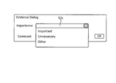
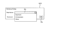
- the importance input section 52a may be a selection-type input section such as the importance input section 52c shown in FIG. 6A.
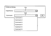
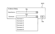
- the comment input section 52b may be a selectable input section such as the comment input section 52d shown in FIG. 6B.
- the display processing unit 31b acquires comment options (also referred to as supplementary information candidates) from the storage unit 34 and causes the comment input unit 52b of the display unit 32 to display the options.
- the option of the comment may be, for example, information on a gas leak state or information on regulation stored in the storage unit 34 in advance.
- the comment option may be, for example, a comment previously input by the user. Further, the comment options may change according to the inspection image 7 displayed on the display unit 32. For example, as a comment option, the relationship between the comment input by the user in the past and the inspection image 7 to which the comment is attached is learned by artificial intelligence (Artificial Intelligence: AI), and based on the learning result. It may be determined.
- AI Artificial Intelligence
- step S105 when the supplementary information is input, the control unit 35 associates the inspection image data (specifically, the frame configuring the inspection image data) displayed on the display unit 32 with the supplementary information. Then, it is stored in the storage unit 34.
- the inspection image data associated with the supplementary information is the inspection image data displayed on the display unit 32 while the second input image 52 is displayed on the display unit 32.
- the inspection image data associated with the supplementary information is displayed at the timing when the second input image 52 is displayed on the display unit 32 (when the first input image 51 of the display unit 32 shown in FIG. 5A is operated). Only the inspection image data (frames constituting the inspection image data) displayed at 32 may be used.
- the range of the inspection image data associated with the supplementary information may be specified by a user's selection operation.
- step S106 of FIG. 2 the control unit 35 determines whether or not there is an instruction to end imaging.
- An instruction to end imaging is input by the user from the operation input unit 33.
- step S106 If it is determined in step S106 that there is no instruction to end imaging (“NO” in step S106), the control process proceeds to step S104. On the other hand, if it is determined in step S106 that an instruction to end imaging has been given (“YES” in step S106), the control process proceeds to step S107.
- step S107 the control unit 35 ends the imaging by the imaging device 2. Then, the control process ends.
- the gas detection device 1 starts the regeneration flow shown in FIG.
- the following processing is realized, for example, by the CPU 35a executing a predetermined program stored in the ROM 35c in response to an instruction to start regeneration in the gas detection device 1.
- step S201 of FIG. 3 the display processing unit 31b acquires inspection image data from the storage unit 34 under the control of the control unit 35.
- the display processing unit 31b converts the acquired inspection image data into a display signal corresponding to the display unit 32 and outputs the display signal, and causes the display unit 32 to display the inspection image 7. In this way, the inspection image data stored in the storage unit 34 is reproduced on the display unit 32.
- the display processing unit 31b constantly displays the supplementary information input image 5 (specifically, the first input image 51) for inputting supplementary information on the display unit 32 during the reproduction of the inspection image data (FIG. 7A).
- the display processing unit 31b always displays the seek bar image 53 (see FIG. 7A) on the display unit 32 during the reproduction of the inspection image data.
- step S202 of FIG. 3 the control unit 35 determines whether or not there is an instruction to input supplementary information.
- the presence or absence of the input instruction is determined based on, for example, whether or not the user has performed a touch operation on the first input image 51.
- step S202 If it is determined in step S202 that there is no instruction to input supplementary information ("NO” in step S202), the control process proceeds to step S204. On the other hand, when it is determined in step S202 that there is an instruction to input supplementary information (“YES” in step S202), the control process proceeds to step S203.
- step S203 of FIG. 3 the display processing unit 31b causes the display unit 32 to display the second input image 52 under the control of the control unit 35 (see FIG. 7B).
- the user inputs supplementary information from the second input image 52 displayed on the display unit 32 in step S203.
- step S203 the user inputs, from the second input image 52, supplementary information on the reproduced and displayed inspection image 7 while the inspection image 7 is being reproduced and displayed on the display unit 32.
- the processing of the gas detection device 1 in step S203 is also referred to as supplementary information input processing.
- the supplementary information input processing is the same as in the above-described imaging flow, and thus the description is omitted.
- step S203 when the supplementary information is input, the control unit 35 associates the inspection image data reproduced on the display unit 32 (specifically, a frame forming the inspection image data) with the supplementary information. Then, it is stored in the storage unit 34.
- the inspection image data associated with the supplementary information is the inspection image data displayed on the display unit 32 while the second input image 52 is displayed on the display unit 32.
- the display processing unit 31b controls the display unit 32 so as to additionally display the third mark 53e indicating the position where the supplementary information is added in the inspection image data on the seek bar image 53. .
- the reproduction position in the seek bar image 53 that is, the reproduction position mark 53g
- the position of the already input supplementary information for example, the third mark 53e
- the display processing unit 31b may cause the display unit 32 to display the content of the supplementary information.
- the reproduction position in the seek bar image 53 (that is, the position of the reproduction position mark 53g in the seek bar image 53) is separated from the third mark 53e by a predetermined distance. Then, the display processing unit 31b controls the display unit 32 so as to end the display of the content of the supplementary information.
- step S204 of FIG. 3 the control unit 35 determines whether or not there is an instruction to end the reproduction.
- An instruction to end imaging is input by the user from the operation input unit 33.
- step S204 If it is determined in step S204 that there is no instruction to end the reproduction ("NO” in step S204), the control process proceeds to step S202. On the other hand, if it is determined in step S204 that there is an instruction to end the reproduction ("YES" in step S204), the control process proceeds to step S205.
- step S205 the control unit 35 ends the reproduction. Then, the control process ends.
- the gas detection device 1 When the output instruction is input from the operation input unit 33, the gas detection device 1 starts the output flow shown in FIG. The following processing is realized, for example, by the CPU 35a executing a predetermined program stored in the ROM 35c in response to an input of an output instruction in the gas detection device 1.
- step S301 of FIG. 4 the control unit 35 determines whether or not there is imaging information.
- step S301 If it is determined in step S301 that there is no imaging information ("NO" in step S301), the control process ends. That is, even when the output instruction is input, the gas detection device 1 prohibits the generation of the output information when the imaging information has not been input.
- step S301 determines whether there is imaging information ("YES" in step S301). If it is determined in step S301 that there is imaging information ("YES" in step S301), the control process proceeds to step S302.
- step S302 in FIG. 4 the output processing unit 31c generates output information including imaging information and inspection image data under the control of the control unit 35.
- the output information may include information other than the imaging information and the image data.
- the user can specify information included in the output information from the operation input unit 33.
- the output processing unit 31c may extract the inspection image data associated with the supplementary information from the inspection image data and generate the output information.
- the output information may include inspection image data associated with supplementary information of the inspection image data.
- the user may specify the range of the inspection image data to be extracted as the output information from the operation input unit 33.
- the output information includes the inspection image data corresponding to the range in the inspection image data.
- the imaging information of the output information generated in step S302 may include, for example, at least the items described in Table 1 above.
- step S303 in FIG. 4 under the control of the control unit 35, the output processing unit 31c outputs the output information to an output terminal (such as a printer) or a storage medium (such as an optical disk, a magneto-optical disk, or a memory card) specified by the user. To a portable storage medium). Note that the output processing unit 31c may automatically attach the output information to a certificate (certification file) relating to the inspection target. Then, the output flow control process ends.
- an output terminal such as a printer
- a storage medium such as an optical disk, a magneto-optical disk, or a memory card
- Supplementary information of any content can be input at any timing.
- Such supplementary information is stored in the storage unit 34 in association with the inspection image 7 displayed on the display unit 32 when the supplementary information is input.
- the user can distinguish between a portion having a high importance in the inspection image 7 and a portion which is not so important.
- the user can distinguish a portion having a high degree of importance from a portion of the inspection image 7 to which the supplementary information is attached and a portion not having the importance.
- the inspection image 7 when the inspection image 7 is stored, a portion having low importance is deleted from the inspection image data, so that the data capacity can be reduced.
- the user checks the inspection image 7 later if the user checks mainly the portion of the inspection image 7 to which supplementary information is added, the efficiency of the checking operation can be improved.
- extracting only inspection image data with supplementary information as output information can reduce the data volume of output information and improve the efficiency of output information confirmation work. it can.
- a gas detection device 1 according to another embodiment of the present invention will be described with reference to the drawings.
- the inspector can visually and easily specify the location of the gas leak in the inspection area by visually checking the inspection image displayed on the display unit.
- the importance of the inspection image for the inspector is completely different between the normal inspection image in which gas leakage does not occur in the inspection target and the emergency inspection image in which gas leakage occurs in the inspection target.
- an inspector may want to continuously view inspection images for a predetermined time including a normal inspection image and an emergency inspection image, but want to partially view only an emergency inspection image.
- the gas leak detection device disclosed in Patent Literature 1 does not have a configuration for responding to such a request.
- FIG. 8 is a block diagram of a gas detection device 1 according to another embodiment of the present invention.
- the gas detection device 1 captures an image of an inspection area including an inspection target (a plant or the like) of a gas production facility, for example. Then, the gas detection device 1 performs image processing for detecting gas on the captured image.
- a gas detection device 1 As shown in FIG. 8, a gas detection device 1 according to another embodiment of the present invention includes an imaging device 2 and a gas detection device main body 3.
- an imaging device 2 and a gas detection device main body 3 in the gas detection device 1 according to the above-described embodiment will be mainly described, and the same components will be denoted by the same reference numerals and description thereof will be omitted. I do.
- the infrared sensor used for the second optical system of the imaging device 2 is, for example, a quantum-type indium antimony (InSb) image sensor, a thermal-type thermopile array sensor, a microbolometer, or the like. Generate image data.
- the infrared imaging unit 22 captures an inspection area including an inspection target of the gas production facility (for example, the plant 6a in FIG. 9A), and converts the infrared image data into the processing unit 31 (specifically, image processing). The data is sequentially output to the section 31a).
- the gas detection device main body 3 includes a processing unit 31, a display unit 32, an operation input unit 33, a storage unit 34, a control unit 35, and the like.
- the processing unit 31 includes at least one dedicated hardware (electronic circuit) corresponding to each processing, such as a DSP (Digital Signal Processor), an ASIC (Application Specific Integrated Circuit), or a PLD (Programmable Logic Device).
- the processing unit 31 includes, as functional blocks, an image processing unit 31a, a display processing unit 31b, an output processing unit 31c, a time information generation unit 31d, and the like. Each function of the processing unit 31 described later is realized under the control of the control unit 35.
- the image processing unit 31a receives the infrared image data of the inspection area from the infrared imaging unit 22.
- the image processing unit 31a performs predetermined image processing for detecting gas on the infrared image data of the inspection area.
- the image processing unit 31a detects, for example, a portion where gas exists in the infrared image data, and visualizes the detected portion to generate gas image data.
- a known method can be used to detect the portion where the gas exists.
- the image processing unit 31a gives a specific color (such as red) to a portion where a gas exists in the infrared image data.
- the image processing section 31a corresponds to the "gas detection section" of the present invention.
- the image processing unit 31a receives the visible image data from the visible light imaging unit 21. Then, the image processing unit 31a generates inspection image data obtained by combining gas image data with visible image data. Further, the image processing unit 31a generates temperature image data from the infrared image data. The image processing unit 31a may generate inspection image data obtained by combining gas image data with infrared image data.
- the image processing unit 31a outputs the inspection image data to the display processing unit 31b and the storage unit 34.
- the storage unit 34 stores the inspection image data in association with the time at which the infrared image data serving as the basis of the inspection image data was captured. More specifically, the storage unit 34 stores the inspection image data in association with detection time information indicating a time at which gas is detected by the image processing unit 31a. The details of the detection time information will be described later.
- the inspection image data is displayed on the display unit 32 as the inspection image 7 (see FIG. 9A).
- the gas image 7a (see FIG. 9A) corresponding to the gas in the inspection image 7 is given the specific color.
- ⁇ Display processing unit> the function of the display processing unit 31b will be described.
- the function of the display processing unit 31b is realized under the control of the control unit 35.
- Such a display processing unit 31b controls display on a display unit 32 described later.
- the display processing unit 31b causes the display unit 32 to display an imaging information input image (not shown) for inputting imaging information.
- the imaging information includes various information necessary for starting imaging by the imaging device 2.
- the imaging information includes a customer ID (Identification), a user ID, an inspector name, an inspection company name, an inspection date and time, an inspection type, a site name, a facility name, a facility ID, and a GPS (Global Positioning System). Includes the latitude and longitude of the located facility.
- the image data serving as the basis of the imaging information input image is stored in the storage unit 34 in advance.
- the display processing unit 31b converts the inspection image data received from the image processing unit 31a into a display signal corresponding to the display unit 32 and outputs the display signal, and causes the display unit 32 to display the inspection image 7 (see FIG. 9A).
- the display processing unit 31b causes the display unit 32 to display the supplementary information input image 5 (see FIG. 9A) for inputting supplementary information for the examination image 7 together with the examination image 7.
- the supplementary information includes information regarding the importance of the inspection image 7 displayed on the display unit 32 and a comment. Examples of the information on the degree of importance include “important”, “normal”, and “unnecessary”.
- the comment for example, a comment on a gas leak such as "gas leak is occurring" can be given.
- FIG. 9A is a diagram illustrating an example of the inspection image 7 and the supplementary information input image 5 displayed on the display unit 32.
- the supplementary information input image 5 is, for example, an icon.
- the image data serving as the basis of the supplementary information input image 5 is stored in the storage unit 34 in advance.
- the supplementary information input image 5 may be composed of, for example, a plurality of images that are sequentially displayed in a pop-up manner for each input item by a user's touch operation.
- the supplementary information input image 5 includes a first input image 51 (see FIG. 9A) that is always displayed on the display unit 32 together with the inspection image 7, and a user operates the first input image 51 (for example, , A touch operation), and a second input image 52 (FIG. 9B) displayed on the display unit 32.
- the display processing unit 31b causes the display unit 32 to display the second input image 52 when the user operates the first input image 51.
- the second input image 52 has an importance input section 52a and a comment input section 52b.
- the user can arbitrarily input information on the importance of the inspection image 7 displayed on the display unit 32 into the importance input unit 52a. Further, the user can input a comment on the inspection image 7 displayed on the display unit 32 into the comment input unit 52b.
- the importance input section 52a may be an input section in which input items are selectively displayed by pull-down, like the importance input section 52c shown in FIG. 10A.
- the comment input section 52b may be an input section in which input items are selectively displayed by pull-down, like the comment input section 52d shown in FIG. 10B.
- the time at which the first input image 51 is operated is stored in the storage unit 34 in association with the time information of the captured image captured by the imaging device 2 and the time information of the inspection image 7 as the time at which the input is received.
- the supplementary information can be stored not only at the time of recording but also at the time of reproduction.
- the display processing unit 31b deletes the second input image 52 from the display unit 32. Note that the display processing unit 31b may automatically delete the second input image 52 after a predetermined period of time has elapsed since the second input image 52 was pop-up displayed.
- the display processing unit 31b converts the inspection image data stored in the storage unit 34 into the display unit 32 when a reproduction start instruction (hereinafter, referred to as a “reproduction start instruction”) is input through the operation input unit 33. Is converted into a display signal corresponding to and output, and the inspection image 7 is displayed on the display unit 32. At this time, the display processing unit 31b causes the display unit 32 to display the supplementary information input image 5 together with the inspection image 7.
- a reproduction start instruction hereinafter, referred to as a “reproduction start instruction”
- the output processing unit 31c generates output information including inspection image data under the control of the control unit 35.
- the output processing unit 31c generates output information when an output instruction is input from the operation input unit 33.
- the output processing unit 31c outputs the output information to an output device such as a printer, for example.
- the output device may be connected to the gas detection device main body 3 by wire or wirelessly.
- the output device may be connected to the gas detection device main body 3 via a network such as the Internet.
- the output processing unit 31c may output the output information to a portable storage medium such as an optical disk, a magneto-optical disk, and a memory card.
- the output processing unit 31c may output the output information to the server.
- the control unit 35 includes a CPU 35a (Central Processing Unit) as an arithmetic / control device, a RAM 35b (Random Access Memory), and a ROM 35c (Read Only Memory) as a main storage device.
- the ROM 35c stores basic programs and basic setting data.
- the CPU 35a reads out a program corresponding to the processing content from the ROM 35c or the storage unit 34, develops the program on the RAM 35b, and executes the developed program to centrally control the operation of each block of the gas detection device 1.
- the control unit 35 controls the entire gas detection device 1 by controlling the imaging device 2, the display unit 32, the operation input unit 33, and the storage unit 34 according to their respective functions.
- each functional block is realized by the cooperation of the hardware constituting each functional block and the control unit 35. Note that a part or all of the functions of each functional block may be realized by the control unit 35 executing the program.
- the control unit 35 determines the reliability of gas detection based on signals from the peripheral sensors 8 of the temperature sensor 81, the wind speed sensor 82, and the vibration sensor 83.
- the temperature sensor 81 measures the ambient temperature around the gas detection device 1.
- the wind speed sensor 82 measures the wind speed around the gas detection device 1 or around the inspection object. For the wind speed, wind speed information of the shooting location may be obtained using a network.
- the vibration sensor 83 measures a vibration state of the imaging device 2. When the temperature difference between the temperature indicated by the image of the inspection area imaged by the infrared imaging unit 22 and the temperature indicated by the temperature sensor 81 is equal to or lower than a predetermined temperature, the control unit 35 sets the wind speed indicated by the wind speed sensor 82 to a predetermined value or higher.
- control unit 35 stores the time information of the inspection image 7 and the invalid information in the storage unit 34 in association with each other.
- the storage unit 34 is, for example, an auxiliary storage device such as a nonvolatile semiconductor memory (a so-called flash memory) or a hard disk drive.
- the storage unit 34 may be a disk drive that reads and writes information by driving an optical disk such as a CD (Compact Disc) and a DVD (Digital Versatile Disc) and a magneto-optical disk such as an MO (Magneto-Optical disk).
- the storage unit 34 may be a memory card such as a USB memory and an SD card.
- the storage unit 34 stores the imaging information input from the operation input unit 33. Writing of data to the storage unit 34 and reading of data from the storage unit 34 are controlled by the control unit 35.
- the storage unit 34 stores the inspection image data received from the image processing unit 31a.
- the storage unit 34 stores the inspection image data in association with the imaging information.
- the storage unit 34 stores the inspection image data in association with detection time information indicating a time at which gas is detected by the image processing unit 31a.
- the storage unit 34 may store the infrared image data after the image processing received from the image processing unit 31a.
- the storage unit 34 may store the infrared image data after the image processing in association with the imaging information.
- the storage unit 34 may store the detection time information in association with the infrared image data after the image processing.
- the storage unit 34 may store infrared image data before image processing generated by the infrared imaging unit 22.
- the storage unit 34 may store the infrared image data before the image processing in association with the imaging information.
- the storage unit 34 may store the detection time information in association with the infrared image data before image processing.
- the storage unit 34 may store the visible image data generated by the visible light imaging unit 21.
- the storage unit 34 may store the visible image data in association with the imaging information.
- the storage unit 34 may store the detection time information in association with the visible image data.
- the storage unit 34 may store temperature image data.
- the storage unit 34 may store the detection time information in association with the temperature image data.
- the storage unit 34 stores various information input from the operation input unit 33. Specifically, the storage unit 34 stores the supplementary information input from the operation input unit 33. The storage unit 34 stores the supplementary information in association with the inspection image 7 (see FIG. 11A) displayed on the display unit 32 when the supplementary information is input. When the inspection image 7 is a moving image, the storage unit 34 stores the supplementary information in association with the frame constituting the inspection image 7 displayed on the display unit 32 when the supplementary information is input. The supplementary information may be stored in association with each of the infrared image data after the image processing, the infrared image data before the image processing, the visible image data, and the temperature image data.
- information on the reliability of gas detection is stored in association with the inspection image.
- the information relating to the reliability of gas detection may be stored in association with each of the infrared image data after the image processing, the infrared image data before the image processing, the visible image data, and the temperature image data.
- the storage unit 34 stores image data relating to the supplementary information input image 5.
- the display unit 32 is, for example, a display of a portable terminal included in the gas detection device main body 3.
- a liquid crystal display, an organic EL display, or the like can be used.
- the display is a flat panel display with a touch panel.
- the display unit 32 displays a plurality of types of images based on display signals from the display processing unit 31b (see FIG. 8) under the control of the control unit 35. Specifically, the display unit 32 displays an inspection image 7 or the like for the user to visually detect the gas (see FIG. 9A).
- the operation input unit 33 is an input unit and receives, for example, input of imaging information. In addition, the operation input unit 33 receives an operation related to reproduction of inspection image data and an operation related to imaging of the imaging device 2.
- the operation input unit 33 receives an instruction to output information related to imaging.
- the operation input unit 33 may receive, for example, designation of an item included in the output information together with the output instruction.
- the items of the output information include imaging information and other arbitrary information (for example, climate information at the time of imaging).
- the operation input unit 33 is configured by a flat panel display with a touch panel provided integrally with the display unit 32. The user can perform input of imaging information, operation of the imaging device 2, and reproduction operation of inspection image data via the operation input unit 33.
- the operation input unit 33 is not limited to a flat panel display with a touch panel, but may be an input device such as a keyboard, a mouse, or a microphone.
- the gas detection device 1 when gas is detected in the inspection area, a report on gas detection is created and submitted to the client (client). In preparing a report or the like, inspection image data is reproduced to check the inspection image.
- the display processing unit 31b converts the inspection image data read from the storage unit 34 into a display signal corresponding to the display unit 32 and outputs the signal. Display the inspection image 7 (see FIG. 9A).
- the user By visually recognizing the inspection image 7, the user (inspector) specifies information such as the location of the gas leak in the inspection area, the time when the gas leak occurred, and the situation after the gas leak occurred.
- the importance of the inspection image for the user is completely different between a normal inspection image in which gas leakage does not occur in the inspection region and an emergency inspection image in which gas leakage occurs in the inspection region.
- a user may want to continuously view inspection images for a predetermined period of time including a normal inspection image and an emergency inspection image, while partially viewing only an emergency inspection image. is there.
- the display processing unit 31b converts the inspection image data stored in the storage unit 34 into a display signal corresponding to the display unit 32 and outputs the display signal. Then, the inspection image 7 is displayed on the display unit 32. At this time, the display processing unit 31b causes the display unit 32 to display a seek bar image 53 (see FIG. 11A) for visualizing the display position on the time axis together with the inspection image 7.
- the image data serving as the base of the seek bar image 53 is stored in the storage unit 34 in advance.
- the first bar element 53a indicates the time during which no gas was detected.
- the second bar element 53b indicates a time when gas is detected by the image processing unit 31a.
- the third bar element 53p indicates a portion where inspection image data is not present or has been deleted.
- the fourth bar element 53q indicates an invalid part of the inspection image data.
- the fifth bar element 53r indicates a portion where the inspection image 7 has already been reproduced.
- the sixth bar element 53s means an unplayed portion of the inspection image 7.
- the second bar element 53b corresponds to “detection time information” of the present invention.
- the function of the time information generation unit 31d is realized under the control of the control unit 35.
- the time information generating unit 31d generates image data serving as the first bar element 53a and the second bar element 53b based on the time at which the infrared image data serving as the base of the inspection image data was captured.
- the time information generation unit 31d generates image data serving as the basis of the fourth bar element 53q based on the information on reliability stored in the storage unit.
- the time information generation unit 31d generates the fifth bar element 53r and the sixth bar element 53s according to the reproduced part of the inspection image 7.
- the display processing unit 31b displays the first bar element 53a, the second bar element 53b, the third bar element 53p, the fourth bar element 53q, the fifth bar element 53r, and the sixth bar element 53s on the display unit 32 by using a seek bar image. 53 and displayed.
- each of the first mark 53c to the fourth mark 53f shown in FIGS. 11A and 11B is referred to as an evidence mark.
- the evidence mark is displayed on the seek bar image 53.
- the position where the evidence mark is displayed indicates the time when the input of the supplementary information was received (reception time information).
- the evidence mark is a part indicating what supplementary information is added by the user.
- the display processing unit 31b is a third mark 53e that is located after the reproduction position mark 53g (see FIG. 11A, also referred to as a slider) indicating the position where the inspection image is reproduced, and is the mark closest to the reproduction position mark 53g. (For example, display with bold font, highlight display).
- the time information generation unit 31d When the third mark 53e is highlighted and displayed, the time information generation unit 31d generates selection range information 53h indicating a time zone selected corresponding to the third mark 53e.
- the time information generation unit 31d sets a certain time (time zone) between a predetermined time before the position of the third mark 53e and a predetermined time after the position of the third mark 53e as the selection range information. Generated as 53h.
- the fifth mark 53i indicates the front end of the selection range information 53h.
- the sixth mark 53j indicates the rear end of the selection range information 53h. The user can arbitrarily change the selection range information 53h by moving the position of the fifth mark 53i or the sixth mark 53j via the operation input unit 33.
- the first mark 53c reflected and displayed on the seek bar image 53 means a portion to which supplementary information with high importance is added.
- the second mark 53d indicates a portion to which supplemental information with low importance is added.
- the third mark 53e and the fourth mark 53f mean portions to which other supplementary information is added.
- the selection range information 53h includes a third mark 53e.
- the third mark 53e is selected, and selection range information 53h corresponding to the third mark 53e is displayed.
- selection range information (not shown) corresponding to the fourth mark 53f is displayed.
- the output processing unit 31c uses the supplementary information related to the third mark 53e (or the fourth mark 53f) as the output information. Generate and output to another device.
- the gas detection device 1 is connected to a personal computer (PC) via a network
- the other devices include a local folder of the PC, a flash memory such as an SD card, and a gas detection device.
- the server 1 includes an output device such as a printer, and a portable storage medium such as an optical disk.
- the output processing unit 31c When outputting the supplementary information, the output processing unit 31c reads out the inspection image data associated with the third mark 53e (or the fourth mark 53f) from the storage unit 34 and outputs it to another device.
- FIG. 12 is a flowchart illustrating an example of the operation of the gas detection device 1.
- step S400 shown in FIG. 12 the image processing unit 31a acquires infrared image data from the infrared imaging unit 22 and visible light image data from the visible light imaging unit 21.
- step S410 the image processing section 31a generates inspection image data based on the infrared image data and the visible light image data.
- step S420 the control unit 35 causes the storage unit 34 to store the inspection image data.
- step S430 the control unit 35 determines whether or not an instruction to reproduce the inspection image 7 has been input via the operation input unit 33. If a reproduction instruction has been input ("YES” in step S430), the process proceeds to step S440. If a reproduction instruction has not been input (“NO” in step S430), the process returns to a step before step S430.
- step S440 the processing unit 31 generates a playback screen. Specifically, the time information generation unit 31d generates image data of the first bar element 53a, the second bar element 53b, the third bar element 53p, and the fourth bar element 53q.
- step S450 the display processing unit 31b causes the display unit 32 to display a playback screen.
- the seek bar image 53 is displayed in the first area of the playback screen.
- a seek bar image 53 is displayed in the second area of the playback screen.
- the supplementary information input image 5 is displayed in the third area of the reproduced image.
- image processing is performed on the infrared image data of the inspection region imaged by the infrared imaging unit 22 to visualize the gas in the inspection region.
- the inspection image 7 can be visually recognized efficiently based on the second bar element 53b.
- the user can easily select the inspection image 7 corresponding to the second bar element 53b from the inspection images 7, attach the selected inspection image 7 to the report, and send the requester (client). Can be submitted to
- the display processing unit 31b emphasizes and displays the evidence mark according to the position of the reproduction position mark 53g (slider). For example, when the position of the slider is within the predetermined time of the evidence mark, the display processing unit 31b highlights and displays the next evidence mark within the same predetermined time. Thereby, the inspection image 7 can be visually recognized efficiently based on the importance of the highlighted evidence mark.
- the display processing unit 31b designates the reproduction position mark 53g (slider).
- the mark may be returned to a position corresponding to the first frame of the offset value (for example, the number of data for a predetermined number of seconds) and displayed.
- the display processing unit 31b may move the slider to the tap position and display the slider.
- the reproduction of the inspection image 7 is continued from the tap position.
- the display processing unit 31b may hold and display the slider at that position.
- the display processing unit 31b may display the slider in a released state. Thereby, the reproduction of the inspection image 7 is restarted.
- evidence of high importance may be placed in a higher layer.
- less important or unnecessary evidence may be placed in lower layers.
- more updated evidence may be placed on higher layers. If the evidence mark is highlighted, the evidence may be moved to that layer to make it easier to select. Since the position of the layer changes according to the importance of the evidence, the handling of the evidence can be performed easily.
- the time information generating unit 31d generates the selection range information 53h such that the selection range information 53h does not include the fourth bar element 53q indicating an invalid portion of the inspection image data.
- the display processing unit 31b may display the second bar element 53b indicating the time at which gas is detected by changing the color density according to the gas leakage amount. This makes it easier for the user to understand the degree of danger.
- the display processing unit 31b may further display the second bar element 53b in a more emphasized manner. In this case, for example, the display processing unit 31b may display the screen of the inspection image 7 so as to surround the screen with a red frame.
- the display processing unit 31b may cause the seek bar image 53 to reflect the mark indicating the break position of the data at predetermined time intervals.
- the display processing unit 31b displays the seek bar image 53 when the inspection image 7 is reproduced.
- the present invention is not limited to this, and the display may be performed during imaging.
- the display processing unit 31b displays the seek bar image 53 on the inspection image 7, but the infrared image after image processing, the infrared image before image processing, the visible image, or the temperature image May be displayed.
Landscapes
- Engineering & Computer Science (AREA)
- Theoretical Computer Science (AREA)
- Physics & Mathematics (AREA)
- General Physics & Mathematics (AREA)
- General Engineering & Computer Science (AREA)
- Human Computer Interaction (AREA)
- Multimedia (AREA)
- Signal Processing (AREA)
- Quality & Reliability (AREA)
- Computer Vision & Pattern Recognition (AREA)
- Investigating Or Analysing Materials By Optical Means (AREA)
- Examining Or Testing Airtightness (AREA)
Abstract
ガス検出装置は、検査画像における特定の画像に対して、任意の情報を付すことができる。ガス検出装置は、撮像部により撮像される検査領域の赤外画像データに画像処理を施してガスを可視化する画像処理部と、画像処理の結果を反映した検査画像を表示部に表示させる表示処理部と、表示部に表示された検査画像に関する補足情報の入力を受け付ける入力部と、検査画像と補足情報とを対応付けて記憶する記憶部と、を備える。
Description
本発明は、ガス検出装置、ガス検出方法、表示制御方法、およびプログラムに関する。
従来から、ガスの赤外吸光特性を利用して、検査領域におけるガス漏れを検出するガス漏れ検出装置が知られている(特許文献1参照)。
このような特許文献1には、検査対象を含む検査領域の画像(動画)を撮像する赤外線カメラおよび可視光カメラと、赤外線カメラにより撮像された赤外画像データを処理する画像処理部と、表示部と、を有するガス漏れ検出装置が開示されている。画像処理部は、検査領域の画像データからガス漏れによるゆらぎの画像を抽出する。そして、表示部は、可視光カメラにより撮像された検査領域の画像データにゆらぎの画像データを重ね合わせた検査画像を表示する。
上述のような特許文献1に開示されたガス検出装置によれば、検査員は、表示部に表示された検査画像を視認することにより、検査領域におけるガス漏れの場所を視覚的に容易に特定できる。
ところで、検査画像において、たとえば、検査対象の通常時の画像と、検査対象にガス漏れが生じている非常時の画像とでは、画像の重要度が異なる。
このような検査画像は、通常時の画像および非常時の画像を含めた所定時間の画像が必要になることもある一方で、たとえば、特定の画像(たとえば、非常時の画像のみ)が必要となる場合もある。検査画像における特定の画像に対して、ユーザーが補足情報を付すことができれば、検査画像から効率よく当該特定の画像を抽出できる。ただし、特許文献1に開示されたガス検出装置は、このような構成を備えていない。
本発明の目的は、検査画像における特定の画像に対して、補足情報を付すことができるガス検出装置、ガス検出方法、表示制御方法、およびプログラムを提供することである。
本発明に係るガス検出装置の一態様は、撮像部により撮像される検査領域の赤外画像データに画像処理を施してガスを可視化する画像処理部と、画像処理の結果を反映した検査画像を表示部に表示させる表示処理部と、表示部に表示された検査画像に関する補足情報の入力を受け付ける入力部と、を備える。
本発明に係るガス検出装置の一態様は、撮像部により撮像される検査領域の赤外画像データに画像処理を施してガスを可視化する画像処理部と、画像処理の結果に基づいて、ガスを検知するガス検知部と、画像処理の結果を反映した検査画像を表示させるとともに、ガス検知部によりガスが検知された時間を示す検知時間情報を表示させる表示制御を行う表示制御部と、を備える。
本発明に係るガス検出方法の一態様は、ガス検出装置において実行されるガス検出方法であって、撮像部により撮像される検査領域の赤外画像データに画像処理を施してガスを可視化し、画像処理の結果を反映した検査画像を表示部に表示させ、表示部に表示された検査画像に関する補足情報の入力を受け付ける。
本発明に係るガス検出方法の一態様は、ガス検出装置において実行されるガス検出方法であって、撮像部により撮像される検査領域の赤外画像データに画像処理を施してガスを可視化し、画像処理の結果を反映した検査画像を表示部に表示させ、表示部に表示された検査画像に関する補足情報の入力を受け付ける。
本発明に係るプログラムの一態様は、ガスを可視化した検査画像を表示部に表示させるガス検出装置のコンピューターに、撮像部により撮像される検査領域の赤外画像データに画像処理を施してガスを可視化する処理と、画像処理の結果を反映した検査画像を表示部に表示させる処理と、表示部に表示された検査画像に関する補足情報の入力を受け付ける処理と、を実行させる。
本発明によれば、検査画像における特定の画像に対して、補足情報を付すことができるガス検出装置、ガス検出方法、表示制御方法、およびプログラムを提供できる。
以下、本発明に係る実施形態の一例を図面に基づいて詳細に説明する。なお、本発明は、以下の実施形態の構造に限定されるものではない。
図1~図7Bを参照して、本発明の一実施の形態に係るガス検出装置1について説明する。図1は、ガス検出装置1のブロック図である。ガス検出装置1は、たとえば、ガス田の検査対象(プラントなど)を含む検査領域を撮像し、検査領域の赤外線画像データを生成する。そして、ガス検出装置1は、当該赤外線画像データに画像処理を施してガスを可視化した検査画像を生成する。また、本実施形態に係るガス検出装置1の場合、ユーザーは、表示部に表示された検査画像を視認しつつ、当該検査画像に対して任意のタイミングで補足情報を付与できる。以下の説明において、画像には、静止画に限らず動画も含まれる。
[ガス検出装置]
図1に示されるように、ガス検出装置1は、撮像装置2と、ガス検出装置本体3と、を備える。撮像装置2とガス検出装置本体3とは、ケーブル4を介して接続されている。なお、撮像装置2は、ガス検出装置本体3と無線通信を介して接続されてもよい。また、撮像装置2は、ガス検出装置本体3とインターネットなどのネットワークを介して接続されてもよい。
図1に示されるように、ガス検出装置1は、撮像装置2と、ガス検出装置本体3と、を備える。撮像装置2とガス検出装置本体3とは、ケーブル4を介して接続されている。なお、撮像装置2は、ガス検出装置本体3と無線通信を介して接続されてもよい。また、撮像装置2は、ガス検出装置本体3とインターネットなどのネットワークを介して接続されてもよい。
<撮像装置>
撮像装置2は、たとえば、携帯可能なカメラ装置である。なお、撮像装置2は、所定位置に固定されたカメラ装置であってもよい。撮像装置2は、たとえば、後述のガス検出装置本体3の制御部35および撮像装置2が有する制御部(不図示)などにより制御されてよい。
撮像装置2は、たとえば、携帯可能なカメラ装置である。なお、撮像装置2は、所定位置に固定されたカメラ装置であってもよい。撮像装置2は、たとえば、後述のガス検出装置本体3の制御部35および撮像装置2が有する制御部(不図示)などにより制御されてよい。
撮像装置2は、たとえば、ガス検出装置本体3の操作入力部33を介して、ユーザーから撮像開始の指示(以下、「撮像開始指示」という。)が入力された場合に、撮像を開始する。ただし、撮像装置2は、撮像開始指示が入力された場合であっても、ユーザーから後述の撮像情報が入力されていない場合には、撮像を開始しなくてもよい。
具体的には、撮像装置2は、可視光撮像部21および赤外線撮像部22を有する。
<可視光撮像部>
可視光撮像部21は、第一光学系(不図示)、第一光学フィルター(不図示)、および可視光センサー(不図示)などを備える。
可視光撮像部21は、第一光学系(不図示)、第一光学フィルター(不図示)、および可視光センサー(不図示)などを備える。
第一光学系は、被写体となる検査領域から入射した可視光を、可視光センサーに結像させる。
第一光学フィルターは、光学系と可視光センサーを結ぶ光路上に配置された、赤外線カットフィルターなどである。赤外線カットフィルターは、光学系を通過した光から赤外線をカットする。
可視光センサーは、たとえば、CMOSイメージセンサーであって、白黒BWの可視光、または、カラーRGBの可視光をそれぞれ受光して可視画像データを生成する。
このような可視光撮像部21は、たとえば、ガス田の検査対象(たとえば、図5Aのプラント6a)を含む検査領域を撮像し、可視画像データを処理部31(具体的には、画像処理部31a)に順次出力する。
可視光撮像部21により生成される可視画像データは、静止画または動画である。なお、後述の表示部32に表示される検査画像7(図5A参照)が後述の赤外画像データの場合には、可視光撮像部21は省略されてもよい。
<赤外線撮像部>
赤外線撮像部22は、第二光学系(不図示)、第二光学フィルター(不図示)、および赤外線センサー(不図示)などを備える。
赤外線撮像部22は、第二光学系(不図示)、第二光学フィルター(不図示)、および赤外線センサー(不図示)などを備える。
第二光学系は、被写体となる検査領域から入射した赤外線を、赤外線センサーに結像させる。
第二光学フィルターは、第二光学系と赤外線センサーを結ぶ光路上に配置された、バンドパスフィルターなどである。第二光学フィルターは、光学系を通過した赤外線うち、所定波長帯に含まれる赤外線のみを通過させる。第二光学フィルターの通過波長帯は、実質的に、被検出ガスの吸収波長帯域に設定される。たとえば、通過波長帯を3.2~3.4μmの中波長域にした場合、メタンガスなどを検出することができる。
赤外線センサーは、たとえば、量子型のインジウムアンチモン(INSb)イメージセンサー、熱型のサーモパイルアレイセンサー、マイクロボロメーター等であって、赤外線を受光して赤外画像データを生成する。このような赤外線撮像部22は、可視光撮像部21と同期した状態で、検査領域を撮像し、赤外画像データを処理部31(具体的には、画像処理部31a)に順次出力する。
赤外線撮像部22により生成される赤外画像データは、静止画または動画である。このような赤外画像データは、検査領域の温度分布を示す。
<ガス検出装置本体>
ガス検出装置本体3は、撮像装置2からの受信情報を用いて、検査領域に発生したガスを可視化する。このようなガス検出装置本体3は、撮像装置2に通信接続された、タブレット端末、スマートフォン、ラップトップ型端末、またはウェアラブル端末などの携帯端末である。
ガス検出装置本体3は、撮像装置2からの受信情報を用いて、検査領域に発生したガスを可視化する。このようなガス検出装置本体3は、撮像装置2に通信接続された、タブレット端末、スマートフォン、ラップトップ型端末、またはウェアラブル端末などの携帯端末である。
ガス検出装置本体3は、処理部31、表示部32、操作入力部33、記憶部34、および制御部35などを備える。
<処理部>
処理部31は、DSP(Digital Signal Processor)、ASIC(Application Specific Integrated Circuit)、またはPLD(Programmable Logic Device)などの、各処理に応じた少なくとも一つの専用ハードウェア(電子回路)で構成される。処理部31は、機能ブロックとして、画像処理部31a、表示処理部31b、および出力処理部31cなどを有する。後述する処理部31の各機能は、制御部35の制御下で実現される。
処理部31は、DSP(Digital Signal Processor)、ASIC(Application Specific Integrated Circuit)、またはPLD(Programmable Logic Device)などの、各処理に応じた少なくとも一つの専用ハードウェア(電子回路)で構成される。処理部31は、機能ブロックとして、画像処理部31a、表示処理部31b、および出力処理部31cなどを有する。後述する処理部31の各機能は、制御部35の制御下で実現される。
<画像処理部>
以下、画像処理部31aの機能について説明する。画像処理部31aの機能は、制御部35の制御下で実現される。
以下、画像処理部31aの機能について説明する。画像処理部31aの機能は、制御部35の制御下で実現される。
画像処理部31aは、赤外線撮像部22から検査領域の赤外画像データ(以下、「画像処理前の赤外画像データ」という。)を受け取る。そして、画像処理部31aは、検査領域の赤外画像データに所定の画像処理を施して、当該赤外画像データにおいてガスが存在する部分を検出し、検出した部分を可視化する(以下、「ガスの可視化処理」という)。画像処理部31aは、画像処理前の赤外画像データにおいてガスが存在する部分に、特定の色(赤など)を付す。ガスの可視化処理が施された後の赤外画像データを、画像処理後の赤外画像データと呼ぶ。
検査領域の赤外画像データからガスを検出する方法について簡単に説明する。検査領域においてガス漏れが発生すると、検査領域の赤外画像データにおいてガスが存在する部分に、温度変化(つまり、検査領域の赤外画像データにおいて輝度の変化)が生じる。画像処理部31aは、このような温度変化に基づいて、ガスが存在する部分を検出する。なお、ガスの検出方法は、公知の画像処理方法であるため、詳細な説明は省略する。
また、画像処理部31aは、可視光撮像部21から可視画像データ(以下、「画像処理前の可視画像データ」という。)を受け取る。そして、画像処理部31aは、画像処理前の可視画像データに、画像処理後の赤外画像データを合成した検査画像データを生成する。検査画像データは、検査画像7(図5A参照)として表示部に表示される。検査画像7においてガスに対応するガス画像7a(図5A参照)は、上記特定の色が付されている。なお、上述の画像処理後の赤外画像データを、可視画像データと合成することなく、検査画像データとしてもよい。
画像処理部31aは、検査画像データを表示処理部31bに出力する。
画像処理部31aは、検査画像データを記憶部34に出力する。また、画像処理部31aは、画像処理後の赤外画像データを記憶部34に出力してもよい。画像処理部31aは、画像処理前の可視画像データを記憶部34に出力してもよい。
<表示処理部>
以下、表示処理部31bの機能について説明する。表示処理部31bの機能は、制御部35の制御下で実現される。このような表示処理部31bは、後述の表示部32の表示を制御する。
以下、表示処理部31bの機能について説明する。表示処理部31bの機能は、制御部35の制御下で実現される。このような表示処理部31bは、後述の表示部32の表示を制御する。
表示処理部31bは、表示部32に、撮像情報を入力するための撮像情報入力画像(不図示)を表示させる。撮像情報入力画像の基となる画像データは、予め記憶部34に記憶されている。
表示処理部31bは、画像処理部31aから受け取った検査画像データを表示部32に対応する表示信号に変換して出力し、表示部32に、検査画像7(図5A参照)を表示させる。
表示処理部31bは、検査画像7とともに、補足情報を入力するための補足情報入力画像5(図5A参照)を、表示部32に表示させる。
図5Aは、表示部32に表示された検査画像7および補足情報入力画像5の一例を示す図である。補足情報入力画像5は、たとえば、アイコンである。補足情報入力画像5の基となる画像データは、予め記憶部34に記憶されている。補足情報入力画像5は、たとえば、ユーザーのタッチ操作により段階的にポップアップ表示される複数の画像により構成されていてもよい。
本実施形態の場合、補足情報入力画像5は、検査画像7とともに表示部32に常時表示される第一入力画像51(図5A参照)と、ユーザーが第一入力画像51を操作(たとえば、タッチ操作)した場合に表示部32に表示される第二入力画像52(図5B参照)と、により構成されている。
表示処理部31bは、ユーザーにより第一入力画像51が操作された場合、表示部32に、第二入力画像52を表示させる。表示部32に第二入力画像52が表示された状態で、操作入力部33を介して終了指示が入力された場合に、表示処理部31bは、表示部32から第二入力画像52を消す。なお、表示処理部31bは、第二入力画像52の表示から予め決められた所定時間が経過した後、第二入力画像52を消してもよい。つまり、第二入力画像52のようにポップアップ表示された画面は、表示されてから所定時間が経過した後、自動的に消えてもよい。
表示処理部31bは、操作入力部33を介して再生開始の指示(以下、「再生開始指示」という。)が入力された場合に、記憶部34に記憶されている検査画像データを、表示部32に対応する表示信号に変換して出力し、表示部32に検査画像7を表示させる。この際、表示処理部31bは、表示部32に、検査画像7とともに補足情報入力画像5を表示させる。
表示処理部31bは、再生開始指示が入力された場合、表示部32に、シークバー画像53(図7Aおよび図7B参照)を表示させる。シークバー画像53の基となる画像データは、予め記憶部34に記憶されている。ユーザーは、シークバー画像53により、検査画像データの再生状況を確認できる。また、ユーザーは、シークバー画像53を操作することで、検査画像データの再生位置を調整できる。
図7Aを参照して、シークバー画像53について説明する。シークバー画像53において、第一バー要素53a(斜格子が付された部分)は、検査画像データにおいてすでに再生された部分を意味する。また、シークバー画像53において、第二バー要素53b(ハッチングが付された部分)は、たとえば、画像処理部31aの検出結果に基づいて、ガス漏れの発生が機械的に検出された部分を意味する。
シークバー画像53において、第一マーク53cは、ユーザーがチェックした部分を意味する。シークバー画像53において、第二マーク53dは、不要な画像データを意味する。また、シークバー画像53において、第三マーク53eおよび第四マーク53fは、ユーザーにより補足情報が付された部分を意味する。このうちの第三マーク53eは、再生されている位置を示す再生位置マーク53gから、最も近い補足情報(エビデンス)を意味する。また、シークバー画像53において、白塗りの部分は、未再生の部分を意味する。さらに、シークバー画像53において、黒塗りの部分は、データが削除された部分を意味する。
<出力処理部>
出力処理部31cは、制御部35の制御下で、撮像情報および検査画像データを含む出力情報を生成する。出力処理部31cは、操作入力部33から出力指示が入力された場合に、出力情報を生成する。
出力処理部31cは、制御部35の制御下で、撮像情報および検査画像データを含む出力情報を生成する。出力処理部31cは、操作入力部33から出力指示が入力された場合に、出力情報を生成する。
出力処理部31cは、操作入力部33から、検査画像データの範囲が入力された場合に、当該範囲の検査画像データを抽出し出力情報として生成する。なお、出力情報には、たとえば、補足情報と対応付けられた検査画像データを含んでよい。
出力処理部31cは、出力情報を、たとえば、プリンターなどの出力装置に出力する。なお、出力装置は、ガス検出装置本体3と有線接続されていてもよいし、無線接続されていてもよい。また、出力装置は、ガス検出装置本体3とインターネットなどのネットワークを介して接続されていてもよい。出力処理部31cは、出力情報を、光ディスク、光磁気ディスク、およびメモリカードなどの可搬型記憶媒体に出力してもよい。
また、ガス検出装置1が、ネットワークを介してサーバーに接続されている場合には、出力処理部31cは、出力情報を、サーバーに出力してもよい。
<表示部>
表示部32は、たとえば、ガス検出装置本体3を構成する携帯端末のディスプレイである。ディスプレイとしては、液晶ディスプレイ、有機ELディスプレイなどを用いることができる。本実施形態の場合、ディスプレイは、タッチパネル付きのフラットパネルディスプレイである。
表示部32は、たとえば、ガス検出装置本体3を構成する携帯端末のディスプレイである。ディスプレイとしては、液晶ディスプレイ、有機ELディスプレイなどを用いることができる。本実施形態の場合、ディスプレイは、タッチパネル付きのフラットパネルディスプレイである。
表示部32は、制御部35の制御下で、表示処理部31bからの表示信号に基づいて各種画像を表示する。表示部32には、ユーザーが視認によりガスを検出するための検査画像7、ユーザーが補足情報を入力するための補足情報入力画像5、およびユーザーが検査画像データの再生状況を確認するためのシークバー画像53などが表示される(図5A~図7A参照)。
<操作入力部>
操作入力部33は、入力部であって、たとえば、撮像情報の入力および補足情報の入力を受け付ける。また、操作入力部33は、検査画像データの再生に関する操作、および撮像装置2の撮像に関する操作を受け付ける。なお、撮像情報は、撮像装置2による撮像を開始するために必要な種々の情報を含む。撮像情報については、後述する。
操作入力部33は、入力部であって、たとえば、撮像情報の入力および補足情報の入力を受け付ける。また、操作入力部33は、検査画像データの再生に関する操作、および撮像装置2の撮像に関する操作を受け付ける。なお、撮像情報は、撮像装置2による撮像を開始するために必要な種々の情報を含む。撮像情報については、後述する。
操作入力部33は、出力指示を受け付ける。操作入力部33は、出力指示とともに、たとえば、出力情報に含まれる項目の指定を受け付けてもよい。出力情報の項目には、後述の撮像情報やその他の任意情報(たとえば、撮像時の気候情報)が含まれる。
操作入力部33は、出力情報として出力する検査画像データの範囲の指定を受け付けてもよい。ユーザーは、たとえば、表示部32に表示されたシークバー画像53(図7A参照)から、出力する検査画像データの範囲を指定する。
操作入力部33は、撮像する検査領域に対応する撮像情報が入力されている場合(記憶部34に当該撮像情報が記憶されていない場合)のみ、出力指示の入力の受け付けを許可してもよい。
逆に言えば、操作入力部33は、撮像する検査領域に対応する撮像情報が入力されていない場合(記憶部34に当該撮像情報が記憶されていない場合)に、出力指示の入力の受け付けを禁止してもよい。
また、操作入力部33は、検査画像データに対応付けられた補足情報が入力されている場合(記憶部34に当該補足情報が記憶されていない場合)のみ、出力指示の入力の受け付けを許可してもよい。
逆に言えば、操作入力部33は、検査画像データに対応付けられた補足情報が入力されていない場合(記憶部34に当該補足情報が記憶されていない場合)に、出力指示の入力の受け付けを禁止してもよい。
また、操作入力部33は、検査領域に対応する撮像情報、および、検査画像データに対応する補足情報が入力されている場合のみ、出力指示の入力の受け付けを許可してもよい。
本実施形態の場合、操作入力部33は、表示部32と一体的に設けられたタッチパネル付きのフラットパネルディスプレイで構成される。ユーザーは、操作入力部33を介して、撮像情報の入力、補足情報の入力、撮像装置2の操作、および検査画像データの再生操作を行うことができる。
なお、操作入力部33は、タッチパネル付きのフラットパネルディスプレイに限らず、たとえば、キーボード、マウス、またはマイクなどの入力デバイスであってもよい。
<制御部>
制御部35は、演算/制御装置としてのCPU35a(Central Processing Unit)、RAM35b(Random Access Memory)、および主記憶装置としてのROM35c(Read Only Memory)などを有する。ROM35cには、基本プログラムや基本的な設定データが記憶される。CPU35aは、ROM35cまたは記憶部34から処理内容に応じたプログラムを読み出してRAM35bに展開し、展開したプログラムを実行することにより、ガス検出装置1の各ブロックの動作を集中制御する。このような制御部35は、撮像装置2、表示部32、操作入力部33、および記憶部34を、それぞれの機能に応じて制御することによって、ガス検出装置1の全体制御を行う。
制御部35は、演算/制御装置としてのCPU35a(Central Processing Unit)、RAM35b(Random Access Memory)、および主記憶装置としてのROM35c(Read Only Memory)などを有する。ROM35cには、基本プログラムや基本的な設定データが記憶される。CPU35aは、ROM35cまたは記憶部34から処理内容に応じたプログラムを読み出してRAM35bに展開し、展開したプログラムを実行することにより、ガス検出装置1の各ブロックの動作を集中制御する。このような制御部35は、撮像装置2、表示部32、操作入力部33、および記憶部34を、それぞれの機能に応じて制御することによって、ガス検出装置1の全体制御を行う。
本実施形態では、機能ブロックを構成する各ハードウェアと制御部35とが協働することにより、各機能ブロックの機能が実現される。なお、制御部35がプログラムを実行することにより、各機能ブロックの一部又は全部の機能が実現されるようにしてもよい。
<記憶部>
記憶部34は、たとえば、不揮発性の半導体メモリ(いわゆるフラッシュメモリ)やハードディスクドライブなどの補助記憶装置である。記憶部34は、CD(Compact Disc)、DVD(Digital Versatile Disc)などの光ディスク、MO(Magneto-Optical disk)などの光磁気ディスクを駆動して情報を読み書きするディスクドライブであってもよい。また、たとえば、記憶部34は、USBメモリ、SDカードなどのメモリカードであってもよい。
記憶部34は、たとえば、不揮発性の半導体メモリ(いわゆるフラッシュメモリ)やハードディスクドライブなどの補助記憶装置である。記憶部34は、CD(Compact Disc)、DVD(Digital Versatile Disc)などの光ディスク、MO(Magneto-Optical disk)などの光磁気ディスクを駆動して情報を読み書きするディスクドライブであってもよい。また、たとえば、記憶部34は、USBメモリ、SDカードなどのメモリカードであってもよい。
記憶部34は、操作入力部33から入力された撮像情報を記憶する。記憶部34へのデータの書き込み、記憶部34からのデータの読み出しは、制御部35により制御される。
記憶部34は、画像処理部31aから受け取った検査画像データを記憶する。記憶部34は、検査画像データを、撮像情報と対応付けて記憶する。
記憶部34は、画像処理部31aから受け取った画像処理後の赤外画像データを記憶してもよい。記憶部34は、画像処理後の赤外画像データを、撮像情報と対応付けて記憶してもよい。
記憶部34は、赤外線撮像部22が生成した画像処理前の赤外画像データを記憶してもよい。記憶部34は、画像処理前の赤外画像データを、撮像情報と対応付けて記憶してもよい。
記憶部34は、可視光撮像部21が生成した可視画像データを記憶してもよい。記憶部34は、可視画像データを、撮像情報と対応付けて記憶してもよい。
記憶部34は、操作入力部33から入力された各種情報を記憶する。具体的には、記憶部34は、操作入力部33から入力された補足情報を記憶する。記憶部34は、補足情報を、当該補足情報が入力された際に表示部32に表示されていた検査画像7(図5A参照)と対応付けて記憶する。検査画像7が動画の場合には、記憶部34は、補足情報を、当該補足情報が入力された際に表示部32に表示されていた検査画像7を構成するフレームと対応付けて記憶する。
記憶部34は、補足情報入力画像5に関する画像データを記憶する。また、記憶部34は、シークバー画像53に関する画像データを記憶する。シークバー画像53に関する画像データには、上述の第一バー要素53a、第二バー要素53b、および第一マーク53c~第四マーク53fに関する画像データが含まれる。
<動作例>
つぎに、図2~図4を参照して、本発明の一実施の形態に係るガス検出装置1の動作例を説明する。図2は、ガス検出装置1の撮像フローの一例を示すフローチャートである。図3は、ガス検出装置1の再生フローの一例を示すフローチャートである。図4は、ガス検出装置1の出力フローの一例を示すフローチャートである。
つぎに、図2~図4を参照して、本発明の一実施の形態に係るガス検出装置1の動作例を説明する。図2は、ガス検出装置1の撮像フローの一例を示すフローチャートである。図3は、ガス検出装置1の再生フローの一例を示すフローチャートである。図4は、ガス検出装置1の出力フローの一例を示すフローチャートである。
<撮像フロー>
図1、図2、図5A、および図5Bを参照して、ガス検出装置1の撮像中、ユーザーが任意のタイミングで補足情報を入力する際のガス検出装置1の動作について説明する。ガス検出装置1による撮像は、検査対象を含む検査領域を撮像できる所定位置にガス検出装置1が配置された状態で行われる。ガス検出装置1は、たとえば、三脚に支持された状態で当該所定位置に配置される。
図1、図2、図5A、および図5Bを参照して、ガス検出装置1の撮像中、ユーザーが任意のタイミングで補足情報を入力する際のガス検出装置1の動作について説明する。ガス検出装置1による撮像は、検査対象を含む検査領域を撮像できる所定位置にガス検出装置1が配置された状態で行われる。ガス検出装置1は、たとえば、三脚に支持された状態で当該所定位置に配置される。
操作入力部33から撮像開始の指示が入力されると、ガス検出装置1は、図2に示される撮像フローを開始する。以下の処理は、たとえば、ガス検出装置1において、撮像開始の指示が入力されることに伴い、CPU35aがROM35c(図1参照)に格納されている所定のプログラムを実行することにより実現される。
図2のステップS101において、表示処理部31bは、制御部35の制御下で、表示部32に、撮像情報を入力するための撮像情報入力画像(不図示)を表示させる。換言すれば、ガス検出装置1は、図2のステップS101において、ユーザーに対して、撮像情報の入力を要求する。
図2のステップS101において、ガス検出装置1がユーザーに要求する撮像情報は、たとえば、以下の表1に示される情報である。

図2のステップS101において、制御部35は、これから撮像する検査領域を過去に撮像している場合には、撮像履歴から撮像情報を取得してもよい。撮像履歴は、記憶部34に記憶されている。このような撮像履歴は、検査領域と対応付けられて記憶部34に記憶されている。
図2のステップS102において、制御部35は、撮像情報(撮像履歴から取得した撮像情報も含む。)の入力の有無を判定する。
ステップS102において、撮像情報の入力なしと判定した場合(ステップS102で“NO”)、制御処理は、ステップS101に遷移する。一方、ステップS102において、撮像情報の入力ありと判定した場合(ステップS102で“YES”)、制御処理は、ステップS103に遷移する。なお、図2に示されるフローチャートの変形例として、ステップS102の判定は省略されてもよい。すなわち、ステップS101における撮像情報の入力の有無にかかわらず、制御処理は、ステップS103に遷移してもよい。
図2のステップS103において、撮像装置2は、制御部35の制御下で、検査領域の撮像を開始する。撮像装置2は、撮像中において、可視画像データを処理部31(具体的には、画像処理部31a)に順次出力する。また、撮像装置2は、撮像中において、赤外画像データを処理部31(具体的には、画像処理部31a)に順次出力する。撮像装置2が生成する可視画像データおよび赤外画像データは、順次記憶部34に記憶されてもよい。
また、撮像装置2の撮像中、画像処理部31aは、赤外線撮像部22から赤外画像データを受け取る。そして、画像処理部31aは、受け取った赤外画像データに対して上述のガス可視化処理を施して、画像処理後の赤外画像データを生成する。
また、画像処理部31aは、撮像装置2の撮像中、可視光撮像部21から可視画像データを受け取る。そして、画像処理部31aは、受け取った可視画像データに、画像処理後の赤外画像データを合成した検査画像データを生成する。
画像処理部31aは、撮像装置2の撮像中、生成した検査画像データを表示処理部31bに順次出力する。表示処理部31bは、受け取った検査画像データを表示部32に対応する表示信号に変換して出力し、表示部32に、検査画像7(図5A参照)を表示させる。このように、撮像装置2の撮像中、表示部32には、検査領域の検査画像7がリアルタイムで表示される。
なお、ガス検出装置1が、ネットワークを介してサーバーに接続されている場合には、出力処理部31cは、検査画像7を、サーバーに送信してもよい。サーバーで受信された検査画像7は、サーバーに接続(ネットワークを介した接続を含む。)された表示部(ディスプレイなど)に表示されてもよい。このような構成によれば、撮像者とは別の者が、遠隔地からリアルタイムで、検査領域の検査画像7を視認できる。また、ガス検出装置1は、当該他の者が、遠隔地から後述の補足情報を入力できるように構成されてもよい。
また、表示処理部31bは、撮像装置2の撮像中、補足情報を入力するための補足情報入力画像5(具体的には、第一入力画像51)を、表示部32に常時表示させる。
図2のステップS104において、制御部35は、補足情報の入力指示の有無を判定する。入力指示の有無は、たとえば、ユーザーにより第一入力画像51がタッチ操作されたか否かにより判定される。
ステップS104において、補足情報の入力指示なしと判定された場合(ステップS104で“NO”)、制御処理は、ステップS106に遷移する。一方、ステップS104において、補足情報の入力指示ありと判定された場合(ステップS104で“YES”)、制御処理は、ステップS105に遷移する。
図2のステップS105において、表示処理部31bは、制御部35の制御下で、表示部32に、第二入力画像52を表示させる(図5B参照)。ユーザーは、ステップS105において、表示部32に表示された第二入力画像52から補足情報を入力する。具体的には、ユーザーは、ステップS105において、検査画像7が表示部32に表示された状態で、表示された検査画像7に関する補足情報を、第二入力画像52から入力する。ステップS105におけるガス検出装置1の処理は、補足情報入力処理とも呼ばれる。
図5Bは、第二入力画像52が表示された表示部32の画面を示す図である。第二入力画像52は、重要度入力部52aと、コメント入力部52bと、を有する。ユーザーは、重要度入力部52aに、表示部32に表示された検査画像7の重要度に関する情報を任意で入力できる。重要度に関する情報として、たとえば、「重要」、「普通」、および「不要」などが挙げられる。
また、ユーザーは、コメント入力部52bに、表示部32に表示されている検査画像7に関する任意のコメントを入力できる。コメントとして、たとえば、「ガス漏れ発生中」などガス漏れに関するコメントが挙げられる。上述の重要度に関する情報およびコメントが、補足情報である。
なお、重要度入力部52aは、図6Aに示される重要度入力部52cのような選択式の入力部であってもよい。また、コメント入力部52bは、図6Bに示されるコメント入力部52dのような選択式の入力部であってもよい。
図6Bに示されるコメント入力部52dの場合、表示処理部31bは、記憶部34からコメントの選択肢(補足情報候補ともいう。)を取得して、表示部32のコメント入力部52bに表示させる。コメントの選択肢は、たとえば、予め記憶部34に記憶された、ガスの漏洩状態に関する情報や規制などに関する情報であってもよい。
また、コメントの選択肢は、たとえば、ユーザーが過去に入力したコメントであってもよい。また、コメントの選択肢は、表示部32に表示された検査画像7に応じて変わってもよい。たとえば、コメントの選択肢は、人口知能(Artificial Intelligence : AI)により、過去にユーザーから入力されたコメントと、当該コメントが付された検査画像7との関係を学習しておき、学習結果に基づいて決定されてもよい。
ステップS105において、補足情報が入力されると、制御部35は、表示部32に表示されていた検査画像データ(具体的には、検査画像データを構成するフレーム)と、補足情報とを対応付けて、記憶部34に記憶させる。補足情報と対応付けられる検査画像データは、第二入力画像52が表示部32に表示されている間、表示部32に表示されていた検査画像データである。
補足情報と対応付けられる検査画像データは、第二入力画像52が表示部32に表示されたタイミング(図5Aに示される表示部32の第一入力画像51が操作されたタイミング)で、表示部32に表示されていた検査画像データ(検査画像データを構成するフレーム)のみであってもよい。
なお、ステップS105の補足情報入力処理において、補足情報と対応付けられる検査画像データの範囲は、ユーザーの選択操作により指定されてもよい。
図2のステップS106において、制御部35は、撮像終了の指示の有無を判定する。撮像終了の指示は、操作入力部33からユーザーにより入力される。
ステップS106において、撮像終了の指示なしと判定した場合(ステップS106で“NO”)、制御処理は、ステップS104に遷移する。一方、ステップS106において、撮像終了の指示ありと判定した場合(ステップS106で“YES”)、制御処理は、ステップS107に遷移する。
ステップS107において、制御部35は、撮像装置2による撮像を終了する。そして、制御処理は終了する。
<再生フロー>
図1、図3、図7A、および図7Bを参照して、記憶部34に記憶された検査画像データの再生中、ユーザーが任意にタイミングで補足情報を入力する際のガス検出装置1の動作について説明する。
図1、図3、図7A、および図7Bを参照して、記憶部34に記憶された検査画像データの再生中、ユーザーが任意にタイミングで補足情報を入力する際のガス検出装置1の動作について説明する。
操作入力部33から再生開始の指示が入力されると、ガス検出装置1は、図3に示される再生フローを開始する。以下の処理は、たとえば、ガス検出装置1において、再生開始の指示が入力されることに伴い、CPU35aがROM35cに格納されている所定のプログラムを実行することにより実現される。
図3のステップS201において、表示処理部31bは、制御部35の制御下で、記憶部34から検査画像データを取得する。表示処理部31bは、取得した検査画像データを表示部32に対応する表示信号に変換して出力し、表示部32に、検査画像7を表示させる。このようにして、記憶部34に記憶された検査画像データが、表示部32で再生される。
また、表示処理部31bは、検査画像データの再生中、補足情報を入力するための補足情報入力画像5(具体的には、第一入力画像51)を、表示部32に常時表示させる(図7A参照)。
また、表示処理部31bは、検査画像データの再生中、シークバー画像53(図7A参照)を表示部32に常時表示させる。
図3のステップS202において、制御部35は、補足情報の入力指示の有無を判定する。入力指示の有無は、たとえば、ユーザーにより第一入力画像51がタッチ操作されたか否かにより判定される。
ステップS202において、補足情報の入力指示なしと判定した場合(ステップS202で“NO”)、制御処理は、ステップS204に遷移する。一方、ステップS202において、補足情報の入力指示ありと判定した場合(ステップS202で“YES”)、制御処理は、ステップS203に遷移する。
図3のステップS203において、表示処理部31bは、制御部35の制御下で、表示部32に、第二入力画像52を表示させる(図7B参照)。ユーザーは、ステップS203において、表示部32に表示された第二入力画像52から補足情報を入力する。具体的には、ユーザーは、ステップS203において、検査画像7が表示部32に再生表示された状態で、再生表示された検査画像7に関する補足情報を、第二入力画像52から入力する。ステップS203におけるガス検出装置1の処理は、補足情報入力処理とも呼ばれる。補足情報入力処理については、上述の撮像フローの場合と同様であるため、説明を省略する。
ステップS203において、補足情報が入力されると、制御部35は、表示部32に再生されていた検査画像データ(具体的には、検査画像データを構成するフレーム)と、補足情報とを対応付けて、記憶部34に記憶させる。補足情報と対応付けられる検査画像データは、第二入力画像52が表示部32に表示されている間、表示部32に表示されていた検査画像データである。
また、補足情報が入力されると、表示処理部31bは、検査画像データにおいて補足情報が付された位置を示す第三マーク53eをシークバー画像53に追加表示するように、表示部32を制御する。
なお、検査画像データの再生中、シークバー画像53における再生位置(つまり、再生位置マーク53g)と、すでに入力された補足情報の位置(たとえば、第三マーク53e)とが、所定範囲内に近づいた場合、表示処理部31bは、補足情報の内容を表示部32に表示させてもよい。
また、補足情報の内容が表示部32に表示された状態において、シークバー画像53における再生位置(つまり、シークバー画像53における再生位置マーク53gの位置)が、第三マーク53eから所定距離だけ離れた場合には、表示処理部31bは、補足情報の内容の表示を終了するように表示部32を制御する。
図3のステップS204において、制御部35は、再生終了の指示の有無を判定する。撮像終了の指示は、操作入力部33からユーザーにより入力される。
ステップS204において、再生終了の指示なしと判定した場合(ステップS204で“NO”)、制御処理は、ステップS202に遷移する。一方、ステップS204において、再生終了の指示ありと判定した場合(ステップS204で“YES”)、制御処理は、ステップS205に遷移する。
ステップS205において、制御部35は、再生を終了する。そして、制御処理は終了する。
<出力フロー>
図4を参照して、ガス検出装置1が出力情報を生成し出力する際の動作について説明する。
図4を参照して、ガス検出装置1が出力情報を生成し出力する際の動作について説明する。
操作入力部33から出力指示が入力されると、ガス検出装置1は、図4に示される出力フローを開始する。以下の処理は、たとえば、ガス検出装置1において、出力指示が入力されることに伴い、CPU35aがROM35cに格納されている所定のプログラムを実行することにより実現される。
図4のステップS301において、制御部35は、撮像情報の有無を判定する。
ステップS301において、撮像情報なしと判定した場合(ステップS301で“NO”)、制御処理は、終了する。つまり、ガス検出装置1は、出力指示が入力された場合でも、撮像情報が未入力である場合には、出力情報の生成を禁止する。
一方、ステップS301において、撮像情報ありと判定した場合(ステップS301で“YES”)、制御処理は、ステップS302に遷移する。
図4のステップS302において、出力処理部31cは、制御部35の制御下で、撮像情報および検査画像データを含む出力情報を生成する。なお、出力情報は、撮像情報および画像データ以外の情報を含んでもよい。ユーザーは、出力情報に含まれる情報を、操作入力部33から指定できる。
なお、ステップS302において、出力処理部31cは、検査画像データのうちの補足情報と対応付けられた検査画像データを抽出し、出力情報を生成してもよい。換言すれば、出力情報は、検査画像データのうちの補足情報と対応付けられた検査画像データを含んでもよい。
また、ステップS302において、ユーザーは、出力情報として抽出する検査画像データの範囲を、操作入力部33から指定してもよい。この場合には、出力情報は、検査画像データのうちの当該範囲に該当する検査画像データを含む。
なお、ステップS302において生成される出力情報の撮像情報は、たとえば、少なくとも上記表1に記載の項目を含んでよい。
図4のステップS303において、出力処理部31cは、制御部35の制御下で、出力情報を、ユーザーから指定された出力端末(プリンターなど)または記憶媒体(光ディスク、光磁気ディスク、またはメモリカードなどの可搬型記憶媒体)に出力する。なお、出力処理部31cは、出力情報を、検査対象に関する証明書(証明ファイル)に自動添付してもよい。そして、出力フローの制御処理は終了する。
<作用・効果>
上述のような本発明の一実施の形態に係るガス検出装置1の場合、ガス検出装置1の撮像中および再生中、ユーザーは、表示部32に表示されている検査画像7を視認しつつ、任意のタイミングで任意の内容の補足情報を入力できる。このような補足情報は、当該補足情報が入力された際に表示部32に表示されていた検査画像7と対応付けられて記憶部34に記憶される。ユーザーは、補足情報を付すことにより、検査画像7において重要度が高い部分と、そうでない部分とを区別できる。また、ユーザーは、補足情報により検査画像7に意味付けすることで、補足情報を付した検査画像7において重要度が高い部分とそうでない部分とを区別できる。この結果、たとえば、検査画像7を保管する際、重要度が低い部分を検査画像データから削除することにより、データ容量の削減を図れる。また、ユーザーが、後から検査画像7を確認する場合に、検査画像7において補足情報が付された部分を中心に確認すれば、確認作業の効率を向上できる。さらに、出力情報を生成し出力する際、出力情報として、補足情報が付された検査画像データのみを抽出すれば、出力情報のデータ容量の低減を図れるとともに、出力情報の確認作業の効率を向上できる。
上述のような本発明の一実施の形態に係るガス検出装置1の場合、ガス検出装置1の撮像中および再生中、ユーザーは、表示部32に表示されている検査画像7を視認しつつ、任意のタイミングで任意の内容の補足情報を入力できる。このような補足情報は、当該補足情報が入力された際に表示部32に表示されていた検査画像7と対応付けられて記憶部34に記憶される。ユーザーは、補足情報を付すことにより、検査画像7において重要度が高い部分と、そうでない部分とを区別できる。また、ユーザーは、補足情報により検査画像7に意味付けすることで、補足情報を付した検査画像7において重要度が高い部分とそうでない部分とを区別できる。この結果、たとえば、検査画像7を保管する際、重要度が低い部分を検査画像データから削除することにより、データ容量の削減を図れる。また、ユーザーが、後から検査画像7を確認する場合に、検査画像7において補足情報が付された部分を中心に確認すれば、確認作業の効率を向上できる。さらに、出力情報を生成し出力する際、出力情報として、補足情報が付された検査画像データのみを抽出すれば、出力情報のデータ容量の低減を図れるとともに、出力情報の確認作業の効率を向上できる。
<他の実施の形態>
次に、本発明の他の実施の形態に係るガス検出装置1ついて、図面を参照しながら説明する。
特許文献1に開示されたガス漏れ検出装置1によれば、検査員は、表示部に表示された検査画像を視認することにより、検査領域におけるガス漏れの場所を視覚的に容易に特定できる。ところで、検査対象にガス漏れが生じていない通常時の検査画像と、検査対象にガス漏れが生じている非常時の検査画像とでは、検査員にとっての検査画像の重要度が全く異なる。たとえば、検査員は、通常時の検査画像および非常時の検査画像を含めた所定時間の検査画像を連続的に視認したい場合がある一方で、非常時の検査画像のみを部分的に視認したいという要請がある。しかしながら、特許文献1に開示されたガス漏れ検出装置には、そのような要請に応えるための構成を備えていない。
次に、本発明の他の実施の形態に係るガス検出装置1ついて、図面を参照しながら説明する。
特許文献1に開示されたガス漏れ検出装置1によれば、検査員は、表示部に表示された検査画像を視認することにより、検査領域におけるガス漏れの場所を視覚的に容易に特定できる。ところで、検査対象にガス漏れが生じていない通常時の検査画像と、検査対象にガス漏れが生じている非常時の検査画像とでは、検査員にとっての検査画像の重要度が全く異なる。たとえば、検査員は、通常時の検査画像および非常時の検査画像を含めた所定時間の検査画像を連続的に視認したい場合がある一方で、非常時の検査画像のみを部分的に視認したいという要請がある。しかしながら、特許文献1に開示されたガス漏れ検出装置には、そのような要請に応えるための構成を備えていない。
図8は、本発明の他の実施の形態に係るガス検出装置1のブロック図である。ガス検出装置1は、たとえば、ガス生産施設の検査対象(プラントなど)を含む検査領域を撮像する。そして、ガス検出装置1は、撮像した画像に対してガスを検出するための画像処理を行う。
[ガス検出装置]
図8に示すように、本発明の他の実施の形態に係るガス検出装置1は、撮像装置2と、ガス検出装置本体3と、を備える。以下の説明においては、上記実施の形態に係るガス検出装置1における撮像装置2およびガス検出装置本体3と異なる構成について主に説明し、同じ構成については、同一符号を付してその説明を省略する。
図8に示すように、本発明の他の実施の形態に係るガス検出装置1は、撮像装置2と、ガス検出装置本体3と、を備える。以下の説明においては、上記実施の形態に係るガス検出装置1における撮像装置2およびガス検出装置本体3と異なる構成について主に説明し、同じ構成については、同一符号を付してその説明を省略する。
撮像装置2の第二光学系に用いられる赤外線センサーは、たとえば、量子型のインジウムアンチモン(InSb)イメージセンサー、熱型のサーモパイルアレイセンサー、マイクロボロメーター等であって、赤外線を受光して赤外画像データを生成する。このような赤外線撮像部22は、たとえば、ガス生産施設の検査対象(たとえば、図9Aのプラント6a)を含む検査領域を撮像し、赤外画像データを処理部31(具体的には、画像処理部31a)に順次出力する。
<ガス検出装置本体>
ガス検出装置本体3は、処理部31、表示部32、操作入力部33、記憶部34、および制御部35などを備える。
ガス検出装置本体3は、処理部31、表示部32、操作入力部33、記憶部34、および制御部35などを備える。
<処理部>
処理部31は、DSP(Digital Signal Processor)、ASIC(Application Specific Integrated Circuit)、またはPLD(Programmable Logic Device)などの、各処理に応じた少なくとも一つの専用ハードウェア(電子回路)で構成される。処理部31は、機能ブロックとして、画像処理部31a、表示処理部31b、出力処理部31c、および、時間情報生成部31dなどを有する。後述する処理部31の各機能は、制御部35の制御下で実現される。
処理部31は、DSP(Digital Signal Processor)、ASIC(Application Specific Integrated Circuit)、またはPLD(Programmable Logic Device)などの、各処理に応じた少なくとも一つの専用ハードウェア(電子回路)で構成される。処理部31は、機能ブロックとして、画像処理部31a、表示処理部31b、出力処理部31c、および、時間情報生成部31dなどを有する。後述する処理部31の各機能は、制御部35の制御下で実現される。
<画像処理部>
以下、画像処理部31aの機能について説明する。
以下、画像処理部31aの機能について説明する。
画像処理部31aは、赤外線撮像部22から検査領域の赤外画像データを受け取る。
画像処理部31aは、検査領域の赤外画像データにガスを検出するための所定の画像処理を施す。
画像処理部31aは、たとえば、赤外画像データにおいてガスが存在する部分を検出し、検出した部分を可視化してガス画像データを生成する。ガスが存在する部分の検出は公知の方法が利用できる。画像処理部31aは、赤外画像データにおいてガスが存在する部分に、特定の色(赤など)を付す。画像処理部31aは、本発明の「ガス検知部」に対応する。
画像処理部31aは、可視光撮像部21から可視画像データを受け取る。そして、画像処理部31aは、可視画像データに、ガス画像データを合成した検査画像データを生成する。また、画像処理部31aは赤外画像データから温度画像データを生成する。画像処理部31aは、赤外画像データにガス画像データを合成した検査画像データを生成してもよい。
画像処理部31aは、検査画像データを表示処理部31bおよび記憶部34に出力する。記憶部34は、検査画像データを、その検査画像データの基となる赤外画像データが撮像された時間と対応付けて記憶する。さらに言えば、記憶部34は、検査画像データを、画像処理部31aによりガスが検知された時間を示す検知時間情報と対応付けて記憶する。なお、検知時間情報の詳細については後述する。
検査画像データは、検査画像7(図9Aを参照)として表示部32に表示される。検査画像7においてガスに対応するガス画像7a(図9Aを参照)は、上記特定の色が付されている。
<表示処理部>
以下、表示処理部31bの機能について説明する。表示処理部31bの機能は、制御部35の制御下で実現される。このような表示処理部31bは、後述の表示部32の表示を制御する。
以下、表示処理部31bの機能について説明する。表示処理部31bの機能は、制御部35の制御下で実現される。このような表示処理部31bは、後述の表示部32の表示を制御する。
表示処理部31bは、表示部32に、撮像情報を入力するための撮像情報入力画像(不図示)を表示させる。ここで、撮像情報には、撮像装置2による撮像を開始するために必要な種々の情報が含まれる。たとえば、撮像情報には、顧客ID(Identification)、ユーザーID、検査員の名前、検査会社の名称、検査の日時、検査タイプ、サイト名、施設の名称、施設ID、GPS(Global Positioning System)により測位された施設の緯度、経度などが含まれる。撮像情報入力画像の基となる画像データは、予め記憶部34に記憶されている。
表示処理部31bは、画像処理部31aから受け取った検査画像データを表示部32に対応する表示信号に変換して出力し、表示部32に、検査画像7(図9Aを参照)を表示させる。
表示処理部31bは、検査画像7とともに、検査画像7に対する補足情報を入力するための補足情報入力画像5(図9Aを参照)を表示部32に表示させる。ここで、補足情報には、表示部32に表示された検査画像7の重要度に関する情報およびコメントが含まれる。重要度に関する情報として、たとえば、「重要」、「普通」および「不要」などが挙げられる。コメントとして、たとえば、「ガス漏れ発生中」などのガス漏れに関するコメントが挙げられる。
図9Aは、表示部32に表示された検査画像7および補足情報入力画像5の一例を示す図である。補足情報入力画像5は、たとえば、アイコンである。補足情報入力画像5の基となる画像データは、予め記憶部34に記憶されている。補足情報入力画像5は、たとえば、ユーザーのタッチ操作により入力項目毎に順次ポップアップ表示される複数の画像により構成されていてもよい。
本実施の形態の場合、補足情報入力画像5は、検査画像7とともに表示部32に常時表示される第一入力画像51(図9Aを参照)と、ユーザーが第一入力画像51を操作(たとえば、タッチ操作)した場合に表示部32に表示される第二入力画像52(図9B)と、により構成されている。
表示処理部31bは、ユーザーにより第一入力画像51が操作された場合、表示部32に、第二入力画像52を表示させる。第二入力画像52は、重要度入力部52aと、コメント入力部52bと、を有する。ユーザーは、重要度入力部52aに、表示部32に表示された検査画像7の重要度に関する情報を任意で入力できる。また、ユーザーは、コメント入力部52bに、表示部32に表示された検査画像7に関するコメントを入力できる。なお、重要度入力部52aは、図10Aに示される重要度入力部52cのようなプルダウンで入力項目が選択的に表示される入力部であってもよい。また、コメント入力部52bは、図10Bに示されるコメント入力部52dのようなプルダウンで入力項目が選択的に表示される入力部であってもよい。
第一入力画像51が操作された時間は、入力が受け付けられた時間として、撮像装置2により撮像された撮像画像および検査画像7の時間情報と対応づけられて記憶部34に記憶される。また、補足情報は、録画時だけでなく、再生時にも記憶可能である。
表示部32に第二入力画像52が表示された状態で、操作入力部33を介してOKボタン52eが押下された場合、表示処理部31bは、表示部32から第二入力画像52を消す。なお、表示処理部31bは、第二入力画像52がポップアップ表示されてから予め決められた所定時間が経過した後、第二入力画像52を自動的に消してもよい。
表示処理部31bは、操作入力部33を介して再生開始の指示(以下、「再生開始指示」という)が入力された場合に、記憶部34に記憶されている検査画像データを、表示部32に対応する表示信号に変換して出力し、表示部32に検査画像7を表示させる。この際、表示処理部31bは、表示部32に、検査画像7とともに補足情報入力画像5を表示させる。
<出力処理部>
出力処理部31cは、制御部35の制御下で、検査画像データを含む出力情報を生成する。出力処理部31cは、操作入力部33から出力指示が入力された場合に、出力情報を生成する。
出力処理部31cは、制御部35の制御下で、検査画像データを含む出力情報を生成する。出力処理部31cは、操作入力部33から出力指示が入力された場合に、出力情報を生成する。
出力処理部31cは、出力情報を、たとえば、プリンターなどの出力装置に出力する。なお、出力装置は、ガス検出装置本体3と有線接続されていてもよいし、無線接続されていてもよい。また、出力装置は、ガス検出装置本体3とインターネットなどのネットワークを介して接続されていてもよい。出力処理部31cは、出力情報を、光ディスク、光磁気ディスク、およびメモリカードなどの可搬型記憶媒体に出力してもよい。
また、ガス検出装置1が、ネットワークを介してサーバーに接続されている場合には、出力処理部31cは、出力情報を、サーバーに出力してもよい。
<制御部>
制御部35は、演算/制御装置としてのCPU35a(Central Processing Unit)、RAM35b(Random Access Memory)、および主記憶装置としてのROM35c(Read Only Memory)などを有する。ROM35cには、基本プログラムや基本的な設定データが記憶される。CPU35aは、ROM35cまたは記憶部34から処理内容に応じたプログラムを読み出してRAM35bに展開し、展開したプログラムを実行することにより、ガス検出装置1の各ブロックの動作を集中制御する。このような制御部35は、撮像装置2、表示部32、操作入力部33、および記憶部34を、それぞれの機能に応じて制御することによって、ガス検出装置1の全体制御を行う。
制御部35は、演算/制御装置としてのCPU35a(Central Processing Unit)、RAM35b(Random Access Memory)、および主記憶装置としてのROM35c(Read Only Memory)などを有する。ROM35cには、基本プログラムや基本的な設定データが記憶される。CPU35aは、ROM35cまたは記憶部34から処理内容に応じたプログラムを読み出してRAM35bに展開し、展開したプログラムを実行することにより、ガス検出装置1の各ブロックの動作を集中制御する。このような制御部35は、撮像装置2、表示部32、操作入力部33、および記憶部34を、それぞれの機能に応じて制御することによって、ガス検出装置1の全体制御を行う。
本実施形態では、機能ブロックを構成する各ハードウェアと制御部35とが協働することにより、各機能ブロックの機能が実現される。なお、制御部35がプログラムを実行することにより、各機能ブロックの一部又は全部の機能が実現されるようにしてもよい。
制御部35は、温度センサー81、風速センサー82、振動センサー83の周辺センサー8からの信号に基づいて、ガス検知の信頼性を判断する。温度センサー81はガス検出装置1の周辺気温を測定する。風速センサー82はガス検出装置1の周囲あるいは検査対象周囲の風速を測定する。風速はネットワークを利用して撮影地の風速情報を取得してもよい。振動センサー83は撮像装置2の振動状態を測定する。制御部35は、赤外線撮像部22で撮像された検査領域の画像が示す温度と温度センサー81が示す温度との温度差が所定の温度以下の場合、風速センサー82が示す風速が所定の値以上の場合、あるいは振動センサー83が示す値が所定以上の場合、ガス検知の信頼性が低いと判断し、この時間帯の画像処理によるガス検知の情報は無効と判断する。制御部35は、検査画像7の時間情報と無効の情報とを対応付けて、記憶部34に記憶させる。
<記憶部>
記憶部34は、たとえば、不揮発性の半導体メモリ(いわゆるフラッシュメモリ)やハードディスクドライブなどの補助記憶装置である。記憶部34は、CD(Compact Disc)、DVD(Digital Versatile Disc)などの光ディスク、MO(Magneto-Optical disk)などの光磁気ディスクを駆動して情報を読み書きするディスクドライブであってもよい。また、たとえば、記憶部34は、USBメモリ、SDカードなどのメモリカードであってもよい。
記憶部34は、たとえば、不揮発性の半導体メモリ(いわゆるフラッシュメモリ)やハードディスクドライブなどの補助記憶装置である。記憶部34は、CD(Compact Disc)、DVD(Digital Versatile Disc)などの光ディスク、MO(Magneto-Optical disk)などの光磁気ディスクを駆動して情報を読み書きするディスクドライブであってもよい。また、たとえば、記憶部34は、USBメモリ、SDカードなどのメモリカードであってもよい。
記憶部34は、操作入力部33から入力された撮像情報を記憶する。記憶部34へのデータの書き込み、記憶部34からのデータの読み出しは、制御部35により制御される。
記憶部34は、画像処理部31aから受け取った検査画像データを記憶する。記憶部34は、検査画像データを、撮像情報と対応付けて記憶する。記憶部34は、検査画像データと、画像処理部31aによりガスが検知された時間を示す検知時間情報と対応付けて記憶する。
記憶部34は、画像処理部31aから受け取った画像処理後の赤外画像データを記憶してもよい。記憶部34は、画像処理後の赤外画像データを、撮像情報と対応付けて記憶してもよい。記憶部34は、検知時間情報と画像処理後の赤外画像データと対応付けて記憶してもよい。
記憶部34は、赤外線撮像部22が生成した画像処理前の赤外画像データを記憶してもよい。記憶部34は、画像処理前の赤外画像データを、撮像情報と対応付けて記憶してもよい。記憶部34は、検知時間情報と画像処理前の赤外画像データと対応付けて記憶してもよい。
記憶部34は、可視光撮像部21が生成した可視画像データを記憶してもよい。記憶部34は、可視画像データを、撮像情報と対応付けて記憶してもよい。記憶部34は、検知時間情報と可視画像データと対応付けて記憶してもよい。
記憶部34は温度画像データを記憶してもよい。記憶部34は、検知時間情報と温度画像データと対応付けて記憶してもよい。
記憶部34は、操作入力部33から入力された各種情報を記憶する。具体的には、記憶部34は、操作入力部33から入力された補足情報を記憶する。記憶部34は、補足情報を、当該補足情報が入力された際に表示部32に表示されていた検査画像7(図11A参照)と対応付けて記憶する。検査画像7が動画の場合には、記憶部34は、補足情報を、当該補足情報が入力された際に表示部32に表示されていた検査画像7を構成するフレームと対応付けて記憶する。補足情報は、画像処理後の赤外画像データ、画像処理前の赤外画像データ、可視画像データ、温度画像データのそれぞれと対応付けて記憶してもよい。
また、ガス検知の信頼性に関する情報を、検査画像と対応づけて記憶する。ガス検知の信頼性に関する情報は、画像処理後の赤外画像データ、画像処理前の赤外画像データ、可視画像データ、温度画像データのそれぞれと対応付けて記憶してもよい。
記憶部34は、補足情報入力画像5に関する画像データを記憶する。
<表示部>
表示部32は、たとえば、ガス検出装置本体3を構成する携帯端末のディスプレイである。ディスプレイとしては、液晶ディスプレイ、有機ELディスプレイなどを用いることができる。本実施形態の場合、ディスプレイは、タッチパネル付きのフラットパネルディスプレイである。
表示部32は、たとえば、ガス検出装置本体3を構成する携帯端末のディスプレイである。ディスプレイとしては、液晶ディスプレイ、有機ELディスプレイなどを用いることができる。本実施形態の場合、ディスプレイは、タッチパネル付きのフラットパネルディスプレイである。
表示部32は、制御部35の制御下で、表示処理部31b(図8を参照)からの表示信号に基づいて複数種類の画像を表示する。具体的には、表示部32には、ユーザーが視認によりガスを検出するための検査画像7などが表示される(図9Aを参照)。
<操作入力部>
操作入力部33は、入力部であって、たとえば、撮像情報の入力を受け付ける。また、操作入力部33は、検査画像データの再生に関する操作、および撮像装置2の撮像に関する操作を受け付ける。
操作入力部33は、入力部であって、たとえば、撮像情報の入力を受け付ける。また、操作入力部33は、検査画像データの再生に関する操作、および撮像装置2の撮像に関する操作を受け付ける。
操作入力部33は、撮像に関する情報の出力指示を受け付ける。操作入力部33は、出力指示とともに、たとえば、出力情報に含まれる項目の指定を受け付けてもよい。出力情報の項目には、撮像情報やその他の任意情報(たとえば、撮像時の気候情報)が含まれる。
本実施形態の場合、操作入力部33は、表示部32と一体的に設けられたタッチパネル付きのフラットパネルディスプレイで構成される。ユーザーは、操作入力部33を介して、撮像情報の入力、撮像装置2の操作、および検査画像データの再生操作を行うことができる。
なお、操作入力部33は、タッチパネル付きのフラットパネルディスプレイに限らず、たとえば、キーボード、マウス、またはマイクなどの入力デバイスであってもよい。
以上に説明したガス検出装置1によれば、検査領域についてガスの検出が行われた場合、ガス検出についての報告書が作成されて、依頼者(クライアント)へ提出される。報告書の作成等においては、検査画像を確認するために検査画像データの再生が行われる。操作入力部33を介して再生開始の指示がされた場合、表示処理部31bは、記憶部34から読み出した検査画像データを表示部32に対応する表示信号に変換して出力し、表示部32に検査画像7(図9Aを参照)を表示させる。ユーザー(検査員)は、検査画像7を視認することにより、検査領域におけるガス漏れが生じた箇所、ガス漏れが生じた時間、ガス漏れが生じた後の状況などの情報を特定する。
ところで、検査領域にガス漏れが生じていない通常時の検査画像と、検査領域にガス漏れが生じている非常時の検査画像とでは、ユーザーにとっての検査画像の重要度が全く異なる。たとえば、ユーザーは、通常時の検査画像および非常時の検査画像を含めた所定時間の検査画像を連続的に視認したい場合がある一方で、非常時の検査画像のみを部分的に視認したい場合がある。つまり、ユーザーには、自身の希望に添って検査画像7を効率良く視認したいという要請がある。
そこで、本実施の形態において、表示処理部31bは、再生開始指示が入力された場合、記憶部34に記憶されている検査画像データを、表示部32に対応する表示信号に変換して出力し、表示部32に検査画像7を表示させる。この際、表示処理部31bは、表示部32に、検査画像7とともに、時間軸上での表示位置を可視化するシークバー画像53(図11Aを参照)を表示させる。
シークバー画像53の基となる画像データは、予め記憶部34に記憶されている。図11Aおよび図11Bに、シークバー画像53の構成要素として、第一バー要素53a、第二バー要素53b、第三バー要素53p、第四バー要素53q、第五バー要素53r、および、第六バー要素53sを示す。第一バー要素53aは、ガスが検知されなかった時間を意味する。第二バー要素53bは、画像処理部31aによりガスが検知された時間を意味する。第三バー要素53pは、検査画像データがないか又は削除された部分を意味する。第四バー要素53qは、検査画像データの無効部分を意味する。第五バー要素53rは、検査画像7が既に再生された部分を意味する。第六バー要素53sは、検査画像7の未再生部分を意味する。なお、第二バー要素53bが本発明の「検知時間情報」に対応する。
以下、時間情報生成部31dの機能について説明する。時間情報生成部31dの機能は、制御部35の制御下で実現される。
時間情報生成部31dは、検査画像データの基となる赤外画像データが撮像された時間に基づいて、第一バー要素53aおよび第二バー要素53bの基となる画像データを生成する。時間情報生成部31dは、記憶部34に記憶されている信頼性に関する情報に基づいて、第四バー要素53qの基となる画像データを生成する。
時間情報生成部31dは、検査画像7の再生された部分に応じて、第五バー要素53rおよび第六バー要素53sを生成する。
表示処理部31bは、表示部32に、第一バー要素53a、第二バー要素53b、第三バー要素53p、第四バー要素53q、第五バー要素53rおよび第六バー要素53sを、シークバー画像53に反映して表示させる。
図11Aおよび図11Bを参照して、シークバー画像53に反映して表示されるその他の要素について説明する。以下の説明で、図11Aおよび図11Bに示す第一マーク53cから第四マーク53fのそれぞれのマークを、エビデンスマークを呼ぶ。エビデンスマークは、シークバー画像53上に表示される。エビデンスマークが表示された位置は、補足情報の入力が受け付けられた時間(受付時間情報)を示す。エビデンスマークは、ユーザーによりどのような補足情報が付されているかを示す部分である。
表示処理部31bは、検査画像が再生されている位置を示す再生位置マーク53g(図11Aを参照、スライダーとも呼ばれる)より後であって、再生位置マーク53gから最も近いマークである第三マーク53eを強調して表示(たとえば、環太字のフォント付き表示、ハイライト表示)させる。時間情報生成部31dは、第三マーク53eが強調されて表示されている場合、第三マーク53eに対応して選択された時間帯を示す選択範囲情報53hを生成する。
時間情報生成部31dは、具体的には、第三マーク53eの位置より所定時間前と第三マーク53eの位置より所定時間後とで挟まれた一定の時間(時間帯)を、選択範囲情報53hとして生成する。
図11Aおよび図11Bにおいて、第五マーク53iは、選択範囲情報53hの前端を意味する。また、第六マーク53jは、選択範囲情報53hの後端を意味する。ユーザーは、操作入力部33を介して第五マーク53iまたは第六マーク53jの位置を移動させることにより、選択範囲情報53hを任意に変更できる。
図11Aを参照して、シークバー画像53に反映して表示されるその他の要素について説明する。シークバー画像53に反映して表示される第一マーク53cは、重要度が高い補足情報が付された部分を意味する。第二マーク53dは、重要度が低い補足情報が付された部分を意味する。第三マーク53eおよび第四マーク53fは、これら以外の補足情報が付された部分を意味する。
図11Aおよび図11Bに示すように、選択範囲情報53hには、第三マーク53eが含まれている。図11Aおよび図11Bでは第三マーク53eが選択されており、第三マーク53eに対応する選択範囲情報53hが表示されている。第四マーク53fが選択されると、第四マーク53fに対応する選択範囲情報(不図示)が表示される。
出力処理部31cは、操作入力部33から第三マーク53e(または第四マーク53f)の指定が入力された場合に、第三マーク53e(または第四マーク53f)に係る補足情報を出力情報として生成して、別の機器へ出力する。ここで、別の機器には、たとえば、ガス検出装置1がネットワークを介してパーソナルコンピュータ(PC)に接続されている場合には、PCのローカルフォルダ、SDカードなどのフラッシュメモリー、また、ガス検出装置1がネットワークを介してサーバーに接続されている場合にはそのサーバー、プリンターなどの出力装置、光ディスクなどの可搬型記憶媒体が含まれる。
出力処理部31cは、補足情報を出力する際に、第三マーク53e(または第四マーク53f)と対応付けられた検査画像データを、記憶部34から読み出して、別の機器へ出力する。
次に、ガス検出装置1の動作の一例について図12を参照して説明する。図12は、ガス検出装置1の動作の一例を示すフローチャートである。
先ず、図12に示すステップS400において、画像処理部31aは、赤外線撮像部22から赤外画像データおよび可視光撮像部21から可視光画像データを取得する。
次に、ステップS410において、画像処理部31aは、赤外画像データおよび可視光画像データに基づいて検査画像データを生成する。
次に、ステップS420において、制御部35は、検査画像データを記憶部34に記憶させる。
次に、ステップS430において、制御部35は、操作入力部33を介して検査画像7の再生の指示が入力されたか否かについて判断する。再生の指示が入力された場合(ステップS430で“YES” )、処理は、ステップS440に遷移する。再生の指示が入力されない場合(ステップS430で“NO” )、処理は、ステップS430の前に戻る。
次に、ステップS440において、処理部31は再生画面を生成する。具体的には、時間情報生成部31dは、第一バー要素53a、第二バー要素53b、第三バー要素53p、および、第四バー要素53qの画像データを生成する。
次に、ステップS450において、表示処理部31bは、表示部32に再生画面を表示させる。これにより、再生画面の第一の領域にはシークバー画像53が表示される。再生画面の第二の領域にシークバー画像53が表示される。再生画像の第三の領域には、補足情報入力画像5が表示される。
上記本発明の他の実施の形態に係るガス検出装置1によれば、赤外線撮像部22により撮像される検査領域の赤外画像データに画像処理を施して、検査領域におけるガスを可視化する画像処理部31aと、画像処理の結果に基づいて、ガスを検知するガス検知部(画像処理部31a)と、画像処理の結果を反映した検査画像7を表示させるとともに、画像処理部31aによりガスが検知された時間を示す第二バー要素53b(検知時間情報)を表示させる表示処理部31bと、を備える。これにより、第二バー要素53bに基づいて、検査画像7を効率良く視認することができる。その結果、ユーザーは、検査画像7の中から容易に第二バー要素53bに対応する検査画像7を選択することができ、選択した検査画像7を報告書に添付して、依頼者(クライアント)に提出することができる。
また、上記実施の形態によれば、表示処理部31bは、再生位置マーク53g(スライダー)の位置に応じてエビデンスマークを強調して表示させる。たとえば、表示処理部31bは、スライダーの位置がエビデンスマークの所定時間内にある場合、同じ所定時間内の次のエビデンスマークを強調して表示させる。これにより、強調表示されたエビデンスマークの重要度に基づいて、効率よく検査画像7を視認することができる。
なお、上記実施の形態では、表示処理部31bは、操作入力部33を介して第一マーク53cから第四マーク53fのいずれかが指定された場合、再生位置マーク53g(スライダー)を、指定されたマークからオフセット値(たとえば、所定の秒数間のデータ数)の最初のフレームに相当する位置に戻して表示させてもよい。
また、上記実施の形態では、表示処理部31bは、操作入力部33を介してシークバー画像53におけるスライダー以外の位置がタップされた場合、スライダーを、タップ位置に移動して表示させてもよい。これにより、検査画像7の再生は、タップ位置から継続される。また、表示処理部31bは、操作入力部33を介してスライダーが保持された場合、スライダーをその位置に保持して表示させてもよい。これにより、検査画像7が再生している場合、検査画像7の再生が停止される。また、表示処理部31bは、操作入力部33を介してスライダーがリリースされた場合、スライダーをリリース状態で表示させてもよい。これにより、検査画像7の再生が再開される。
また、上記実施の形態では、重要度の高いエビデンス(補足情報)は、上位のレイヤーに置かれてもよい。これに対し、重要度の低いエビデンス又は不必要なエビデンスは、下位のレイヤーに置かれてもよい。同じ重要度のエビデンスの場合、より更新されたエビデンスが上位のレイヤーに置かれてもよい。エビデンスマークが強調されて表示された場合、そのエビデンスは、そのレイヤーに移動されて、選択され易くしてもよい。エビデンスの重要度に応じて、レイヤーの位置が変わるので、エビデンスの取り扱いを簡便に行うことができる。
また、上記実施の形態においては、時間情報生成部31dは、選択範囲情報53hに検査画像データの無効部分を意味する第四バー要素53qが含まれないように、選択範囲情報53hを生成する。
また、上記実施の形態では、表示処理部31bは、ガスが検知された時間を意味する第二バー要素53bを、ガス漏れ量に応じて色の濃さを変えて表示させてもよい。これにより、ユーザーに危険度がわかり易くなる。表示処理部31bは、ガス漏れ量が所定値を超えた場合、第二バー要素53bをさらに強調して表示させてもよい。この場合、表示処理部31bは、たとえば、検査画像7の画面を赤枠で囲うように表示させてもよい。
また、上記実施の形態では、表示処理部31bは、シークバー画像53に、データの所定時間毎の区切り位置を示すマークを反映して表示させてもよい。
また、上記実施の形態では、表示処理部31bは、シークバー画像53を検査画像7の再生時に表示させたが、本発明は、これに限らず、撮像中に表示させてもよい。
また、上記実施の形態では、表示処理部31bは、シークバー画像53を検査画像7に対し表示させたが、画像処理後の赤外画像、画像処理前の赤外画像、可視画像、あるいは温度画像に対して表示させてもよい。
2018年7月25日出願の特願2018-139158の日本出願、および、2018年8月20日出願の特願2018-153951の日本出願にそれぞれ含まれる明細書、図面および要約書の開示内容は、すべて本願に援用される。
その他、上記実施の形態は、何れも本発明の実施するにあたっての具体化の一例を示したものに過ぎず、これらによって本発明の技術的範囲が限定的に解釈されてはならないものである。すなわち、本発明はその要旨、またはその主要な特徴から逸脱することなく、様々な形で実施することができる。
1 ガス検出装置
2 撮像装置
3 ガス検出装置本体
4 ケーブル
5 補足情報入力画像
6a プラント
7 検査画像
7a ガス画像
21 可視光撮像部
22 赤外線撮像部
31 処理部
31a 画像処理部
31b 表示処理部
31c 出力処理部
31d 時間情報生成部
32 表示部
33 操作入力部
34 記憶部
35 制御部
53 シークバー画像
53a 第一バー要素
53b 第二バー要素
53c 第一マーク
53d 第二マーク
53e 第三マーク
53f 第四マーク
53g 再生位置マーク
53h 選択範囲情報
2 撮像装置
3 ガス検出装置本体
4 ケーブル
5 補足情報入力画像
6a プラント
7 検査画像
7a ガス画像
21 可視光撮像部
22 赤外線撮像部
31 処理部
31a 画像処理部
31b 表示処理部
31c 出力処理部
31d 時間情報生成部
32 表示部
33 操作入力部
34 記憶部
35 制御部
53 シークバー画像
53a 第一バー要素
53b 第二バー要素
53c 第一マーク
53d 第二マーク
53e 第三マーク
53f 第四マーク
53g 再生位置マーク
53h 選択範囲情報
Claims (20)
- 撮像部により撮像される検査領域の赤外画像データに画像処理を施してガスを可視化する画像処理部と、
前記画像処理の結果を反映した検査画像を表示部に表示させる表示処理部と、
前記表示部に表示された前記検査画像に関する補足情報の入力を受け付ける入力部と、を備える、
ガス検出装置。 - 前記検査画像と前記補足情報とを対応付けて記憶する記憶部を、さらに備える、請求項1に記載のガス検出装置。
- 前記入力部は、撮像中に、前記補足情報の入力を受け付ける、請求項1または2に記載のガス検出装置。
- 前記入力部は、前記検査画像の再生中に、前記補足情報の入力を受け付ける、請求項1~3の何れか一項に記載のガス検出装置。
- 前記入力部は、前記表示部に表示された複数の補足情報候補の中からユーザーにより選択された補足情報候補を、前記補足情報として受け付ける、請求項1~4の何れか一項に記載されたガス検出装置。
- 前記検査領域に関する情報を含む撮像情報が入力されている場合に、撮像を許可する一方、前記撮像情報が入力されていない場合に撮像を禁止するように前記撮像部を制御する制御部を、さらに有する、請求項1~5の何れか一項に記載のガス検出装置。
- 前記入力部は、前記検査領域に関する情報を含む撮像情報が入力されている場合に前記補足情報の入力の受け付けを許可する一方、前記撮像情報が入力されていない場合に前記補足情報の入力の受け付けを禁止する、請求項1~6の何れか一項に記載のガス検出装置。
- 少なくとも前記補足情報に対応付けられた前記検査画像と、前記検査領域に関する情報を含む撮像情報と、を含む出力情報を出力する出力処理部を、さらに備える、請求項1~7の何れか一項に記載のガス検出装置。
- 撮像部により撮像される検査領域の赤外画像データに画像処理を施してガスを可視化する画像処理部と、
前記画像処理の結果に基づいて、前記ガスを検知するガス検知部と、
前記画像処理の結果を反映した検査画像を表示させるとともに、前記ガス検知部により前記ガスが検知された時間を示す検知時間情報を表示させる表示制御を行う表示制御部と、
を備える、ガス検出装置。 - 前記表示制御部は、ユーザーの指示に応じて、前記表示制御を行う、
請求項9に記載のガス検出装置。 - 前記検査画像に対する補足情報の入力を受け付ける入力部をさらに備え、
前記表示制御部は、前記表示制御を行う場合、前記入力部により前記補足情報の入力が受け付けられた時間を示す受付時間情報を表示させる、
請求項9または10に記載のガス検出装置。 - 前記表示制御部は、時間軸上での位置を可視化するシークバーに前記検知時間情報を反映して表示させる、
請求項11に記載のガス検出装置。 - 前記表示制御部は、前記受付時間情報を前記シークバーに反映して表示させる表示制御を行う、
請求項12に記載のガス検出装置。 - 前記表示制御部は、ガス検知の信頼性が低いと判断された時間帯を前記シークバーに反映して表示させる表示制御を行う、請求項12に記載のガス検出装置。
- 前記補足情報を外部へ出力する制御を行う出力制御部をさらに備える、
請求項11または12に記載のガス検出装置。 - 前記出力制御部は、前記受付時間情報に対応して選択された時間帯を示す選択範囲情報における検査画像のデータを出力する制御を行う、
請求項15に記載のガス検出装置。 - 前記出力制御部は、前記選択範囲情報における検査画像のデータを、前記受付時間情報に関係する前記補足情報と共に出力する制御を行う、
請求項16に記載のガス検出装置。 - ガス検出装置において実行されるガス検出方法であって、
撮像部により撮像される検査領域の赤外画像データに画像処理を施してガスを可視化し、
前記画像処理の結果を反映した検査画像を表示部に表示させ、
前記表示部に表示された前記検査画像に関する補足情報の入力を受け付ける、
ガス検出方法。 - 撮像部により撮像される検査領域の赤外画像データに画像処理を施してガスを可視化し、
前記画像処理の結果に基づいて、前記ガスを検知し、
前記画像処理の結果を反映した検査画像を表示させるとともに、前記ガスが検知された時間を示す検知時間情報を表示させる表示制御を行う、
表示制御方法。 - ガスを可視化した検査画像を表示部に表示させるガス検出装置のコンピューターに、
撮像部により撮像される検査領域の赤外画像データに画像処理を施してガスを可視化する処理と、
前記画像処理の結果を反映した検査画像を表示部に表示させる処理と、
前記表示部に表示された前記検査画像に関する補足情報の入力を受け付ける処理と、
を実行させるプログラム。
Priority Applications (2)
| Application Number | Priority Date | Filing Date | Title |
|---|---|---|---|
| JP2020532159A JP7359149B2 (ja) | 2018-07-25 | 2019-04-12 | ガス検出装置、ガス検出方法、およびプログラム |
| US17/263,030 US11568529B2 (en) | 2018-07-25 | 2019-04-12 | Gas detection device that visualizes gas |
Applications Claiming Priority (4)
| Application Number | Priority Date | Filing Date | Title |
|---|---|---|---|
| JP2018139158 | 2018-07-25 | ||
| JP2018-139158 | 2018-07-25 | ||
| JP2018-153951 | 2018-08-20 | ||
| JP2018153951 | 2018-08-20 |
Publications (1)
| Publication Number | Publication Date |
|---|---|
| WO2020021785A1 true WO2020021785A1 (ja) | 2020-01-30 |
Family
ID=69182188
Family Applications (1)
| Application Number | Title | Priority Date | Filing Date |
|---|---|---|---|
| PCT/JP2019/015889 Ceased WO2020021785A1 (ja) | 2018-07-25 | 2019-04-12 | ガス検出装置、ガス検出方法、表示制御方法、およびプログラム |
Country Status (3)
| Country | Link |
|---|---|
| US (1) | US11568529B2 (ja) |
| JP (1) | JP7359149B2 (ja) |
| WO (1) | WO2020021785A1 (ja) |
Cited By (3)
| Publication number | Priority date | Publication date | Assignee | Title |
|---|---|---|---|---|
| WO2021181675A1 (ja) * | 2020-03-13 | 2021-09-16 | コニカミノルタ株式会社 | ガス検査管理システム、ガス検査管理方法、及びプログラム |
| JPWO2021205574A1 (ja) * | 2020-04-08 | 2021-10-14 | ||
| WO2022070943A1 (ja) * | 2020-09-29 | 2022-04-07 | コニカミノルタ株式会社 | ガス可視化画像処理装置、ガス可視化画像処理方法、および、プログラム |
Families Citing this family (2)
| Publication number | Priority date | Publication date | Assignee | Title |
|---|---|---|---|---|
| WO2020021785A1 (ja) * | 2018-07-25 | 2020-01-30 | コニカミノルタ株式会社 | ガス検出装置、ガス検出方法、表示制御方法、およびプログラム |
| DE102019132173A1 (de) * | 2019-11-27 | 2021-05-27 | Endress+Hauser Conducta Gmbh+Co. Kg | Verfahren zur Konfiguration zur Übertragung von Daten von einem Feldgerät |
Citations (7)
| Publication number | Priority date | Publication date | Assignee | Title |
|---|---|---|---|---|
| JP2005533997A (ja) * | 2002-05-21 | 2005-11-10 | フリル システムズ アクチボラゲット | Irカメラ検査の方法および装置 |
| JP2009192469A (ja) * | 2008-02-18 | 2009-08-27 | Tokyo Electric Power Co Inc:The | フランジ用アタッチメント、ガス漏れ検知システムおよびコンピュータプログラム |
| JP2010271094A (ja) * | 2009-05-20 | 2010-12-02 | Hitachi High-Technologies Corp | ガスリーク検査装置 |
| JP2013207492A (ja) * | 2012-03-28 | 2013-10-07 | Azbil Corp | 携帯端末装置 |
| US20160097713A1 (en) * | 2014-07-07 | 2016-04-07 | Rebellion Photonics, Inc. | Gas leak emission quantification with a gas cloud imager |
| JP2016161397A (ja) * | 2015-03-02 | 2016-09-05 | コニカミノルタ株式会社 | 流体漏れ検知装置 |
| WO2017022286A1 (ja) * | 2015-08-03 | 2017-02-09 | ソニー株式会社 | 情報処理システム、情報処理方法、および記録媒体 |
Family Cites Families (29)
| Publication number | Priority date | Publication date | Assignee | Title |
|---|---|---|---|---|
| US8269171B2 (en) * | 2008-09-26 | 2012-09-18 | Bae Systems Information And Electronic Systems Integration Inc. | System and method for detecting, tracking and identifying a gas plume |
| WO2011079208A1 (en) * | 2009-12-24 | 2011-06-30 | Flir Systems, Inc. | Cameras with on-board reporting capabilities |
| JP5343054B2 (ja) | 2010-09-09 | 2013-11-13 | 三菱電機ビルテクノサービス株式会社 | ガス漏れ検出装置 |
| JP5585889B2 (ja) * | 2011-08-23 | 2014-09-10 | コニカミノルタ株式会社 | 表示データ生成装置及び表示制御システム並びに表示制御プログラム |
| JP5533837B2 (ja) * | 2011-11-02 | 2014-06-25 | コニカミノルタ株式会社 | 手書き入力装置及び手書き入力制御プログラム |
| JP5900388B2 (ja) * | 2013-03-15 | 2016-04-06 | コニカミノルタ株式会社 | オブジェクト表示装置及び操作制御方法並びに操作制御プログラム |
| JP5818172B2 (ja) * | 2013-06-21 | 2015-11-18 | コニカミノルタ株式会社 | 情報表示装置及び表示制御プログラム並びに表示制御方法 |
| JP6558438B2 (ja) * | 2015-07-17 | 2019-08-14 | コニカミノルタ株式会社 | ガス検知装置およびガス検知方法 |
| WO2017014097A1 (ja) * | 2015-07-17 | 2017-01-26 | コニカミノルタ株式会社 | ガス検知装置およびガス検知方法 |
| US20180222581A1 (en) * | 2015-08-04 | 2018-08-09 | Konica Minolta, Inc. | Gas Detection Device and Gas Detection Method |
| US11287407B2 (en) * | 2015-10-19 | 2022-03-29 | University Of North Texas | Dynamic reverse gas stack model for portable chemical detection devices to locate threat and point-of-source from effluent streams |
| JP6665863B2 (ja) * | 2015-10-29 | 2020-03-13 | コニカミノルタ株式会社 | 漏洩ガス検出装置および漏洩ガス検出方法 |
| WO2017150565A1 (ja) * | 2016-03-03 | 2017-09-08 | コニカミノルタ株式会社 | ガス漏れ位置推定装置、ガス漏れ位置推定方法及びガス漏れ位置推定プログラム |
| EP3436193A1 (en) * | 2016-03-28 | 2019-02-06 | Nanoimmunotech, S.L. | Microfluidics for analyte detection based on the light to heat conversion properties of metal nanoparticles |
| CN109196356B (zh) * | 2016-03-31 | 2021-08-10 | 霍尼韦尔国际公司 | 克莱兹代尔气体检测器 |
| US10916258B2 (en) * | 2017-06-30 | 2021-02-09 | Telegraph Peak Technologies, LLC | Audio channel monitoring by voice to keyword matching with notification |
| JP7238778B2 (ja) * | 2017-09-27 | 2023-03-14 | コニカミノルタ株式会社 | ガス撮像装置及び画像取得方法 |
| WO2019099096A1 (en) * | 2017-11-16 | 2019-05-23 | MultiSensor Scientific, Inc. | Systems and methods for multispectral imaging and gas detection using a scanning illuminator and optical sensor |
| US10914653B2 (en) * | 2018-05-03 | 2021-02-09 | Quantum IR Technologies, LLC | Infrared imaging systems and methods for oil leak detection |
| US10810858B2 (en) * | 2018-05-03 | 2020-10-20 | Quantum IR Technologies, LLC | Infrared imaging systems and methods for gas leak detection |
| WO2019220761A1 (ja) * | 2018-05-16 | 2019-11-21 | コニカミノルタ株式会社 | カメラ装置、ガス漏洩検査システム、ガス漏洩検査方法、及び、ガス漏洩検査プログラム |
| WO2020021785A1 (ja) * | 2018-07-25 | 2020-01-30 | コニカミノルタ株式会社 | ガス検出装置、ガス検出方法、表示制御方法、およびプログラム |
| WO2020039606A1 (ja) * | 2018-08-20 | 2020-02-27 | コニカミノルタ株式会社 | ガス検出装置、情報処理装置およびプログラム |
| WO2020039605A1 (ja) * | 2018-08-20 | 2020-02-27 | コニカミノルタ株式会社 | ガス検出装置、情報処理装置およびプログラム |
| WO2020090125A1 (ja) * | 2018-10-29 | 2020-05-07 | コニカミノルタ株式会社 | 検査支援方法、検査支援装置および検査支援用プログラム |
| EP3975102A4 (en) * | 2019-05-20 | 2022-08-03 | Konica Minolta, Inc. | AUDIT DATA MANAGEMENT SYSTEM, MANAGEMENT DEVICE, MANAGEMENT METHOD AND TERMINAL |
| US11438554B2 (en) * | 2019-08-09 | 2022-09-06 | Mission Support and Test Services, LLC | System and method for remote detection and location of gas leaks |
| JP2021140524A (ja) * | 2020-03-06 | 2021-09-16 | 株式会社東芝 | 検査端末装置、検査装置、検査システム、及び、検査プログラム |
| US11392897B1 (en) * | 2020-08-10 | 2022-07-19 | United Services Automobile Association (Usaa) | Intelligent system and method for assessing structural damage using aerial imagery |
-
2019
- 2019-04-12 WO PCT/JP2019/015889 patent/WO2020021785A1/ja not_active Ceased
- 2019-04-12 US US17/263,030 patent/US11568529B2/en active Active
- 2019-04-12 JP JP2020532159A patent/JP7359149B2/ja active Active
Patent Citations (7)
| Publication number | Priority date | Publication date | Assignee | Title |
|---|---|---|---|---|
| JP2005533997A (ja) * | 2002-05-21 | 2005-11-10 | フリル システムズ アクチボラゲット | Irカメラ検査の方法および装置 |
| JP2009192469A (ja) * | 2008-02-18 | 2009-08-27 | Tokyo Electric Power Co Inc:The | フランジ用アタッチメント、ガス漏れ検知システムおよびコンピュータプログラム |
| JP2010271094A (ja) * | 2009-05-20 | 2010-12-02 | Hitachi High-Technologies Corp | ガスリーク検査装置 |
| JP2013207492A (ja) * | 2012-03-28 | 2013-10-07 | Azbil Corp | 携帯端末装置 |
| US20160097713A1 (en) * | 2014-07-07 | 2016-04-07 | Rebellion Photonics, Inc. | Gas leak emission quantification with a gas cloud imager |
| JP2016161397A (ja) * | 2015-03-02 | 2016-09-05 | コニカミノルタ株式会社 | 流体漏れ検知装置 |
| WO2017022286A1 (ja) * | 2015-08-03 | 2017-02-09 | ソニー株式会社 | 情報処理システム、情報処理方法、および記録媒体 |
Cited By (5)
| Publication number | Priority date | Publication date | Assignee | Title |
|---|---|---|---|---|
| WO2021181675A1 (ja) * | 2020-03-13 | 2021-09-16 | コニカミノルタ株式会社 | ガス検査管理システム、ガス検査管理方法、及びプログラム |
| US12146812B2 (en) | 2020-03-13 | 2024-11-19 | Konica Minolta, Inc. | Gas inspection management system, gas inspection management method, and instructions for gas inspection management |
| JPWO2021205574A1 (ja) * | 2020-04-08 | 2021-10-14 | ||
| WO2021205574A1 (ja) * | 2020-04-08 | 2021-10-14 | コニカミノルタ株式会社 | 施設管理システム |
| WO2022070943A1 (ja) * | 2020-09-29 | 2022-04-07 | コニカミノルタ株式会社 | ガス可視化画像処理装置、ガス可視化画像処理方法、および、プログラム |
Also Published As
| Publication number | Publication date |
|---|---|
| US20210312602A1 (en) | 2021-10-07 |
| US11568529B2 (en) | 2023-01-31 |
| JP7359149B2 (ja) | 2023-10-11 |
| JPWO2020021785A1 (ja) | 2021-08-02 |
Similar Documents
| Publication | Publication Date | Title |
|---|---|---|
| JP7359149B2 (ja) | ガス検出装置、ガス検出方法、およびプログラム | |
| US10796543B2 (en) | Display control apparatus, display control method, camera system, control method for camera system, and storage medium | |
| US10404947B2 (en) | Information processing apparatus, information processing method, camera system, control method for camera system, and storage medium | |
| EP2779632B1 (en) | Electronic device and method of operating the same | |
| KR20170000773A (ko) | 영상 처리 장치 및 방법 | |
| JP7294343B2 (ja) | ガス検出装置、情報処理装置およびプログラム | |
| KR20210056338A (ko) | 이미지들에 대한 다중 영역 검출 | |
| US20240267611A1 (en) | Systems and methods for imaging with a first camera to simulate a second camera | |
| US8866953B2 (en) | Mobile device and method for controlling the same | |
| US11049527B2 (en) | Selecting a recording mode based on available storage space | |
| US20160353021A1 (en) | Control apparatus, display control method and non-transitory computer readable medium | |
| JP6602067B2 (ja) | 表示制御装置、表示制御方法、プログラム | |
| WO2020012864A1 (ja) | ガス検出装置、ガス検出方法、およびプログラム | |
| US20180063344A1 (en) | Mobile device and method for controlling the same | |
| JP6661312B2 (ja) | 監視システム、情報処理方法及びプログラム | |
| US20170078515A1 (en) | Information recording device, information recording method, and non-transitory storage medium storing information recording medium | |
| JP2011119832A (ja) | 画像表示装置および画像表示方法 | |
| US9736380B2 (en) | Display control apparatus, control method, and storage medium | |
| US12464228B2 (en) | Information processing apparatus, control apparatus, and control method | |
| JP2021118492A (ja) | 画像処理装置および画像処理方法 | |
| WO2020075624A1 (ja) | 情報処理装置、情報処理方法、情報提供装置、情報提供方法、提示制御装置、提示制御方法および情報処理システム | |
| JP5517895B2 (ja) | 端末装置 | |
| JP5264274B2 (ja) | 通信装置、カメラシステム、制御方法およびプログラム | |
| JP7546881B2 (ja) | 動画撮影支援システム、動画撮影支援システムの制御方法及びプログラム | |
| JP4478047B2 (ja) | 情報提示装置及び情報提示方法とそのプログラム |
Legal Events
| Date | Code | Title | Description |
|---|---|---|---|
| 121 | Ep: the epo has been informed by wipo that ep was designated in this application |
Ref document number: 19841575 Country of ref document: EP Kind code of ref document: A1 |
|
| ENP | Entry into the national phase |
Ref document number: 2020532159 Country of ref document: JP Kind code of ref document: A |
|
| NENP | Non-entry into the national phase |
Ref country code: DE |
|
| 122 | Ep: pct application non-entry in european phase |
Ref document number: 19841575 Country of ref document: EP Kind code of ref document: A1 |