WO2020021658A1 - 光投影装置および光投影方法 - Google Patents
光投影装置および光投影方法 Download PDFInfo
- Publication number
- WO2020021658A1 WO2020021658A1 PCT/JP2018/027921 JP2018027921W WO2020021658A1 WO 2020021658 A1 WO2020021658 A1 WO 2020021658A1 JP 2018027921 W JP2018027921 W JP 2018027921W WO 2020021658 A1 WO2020021658 A1 WO 2020021658A1
- Authority
- WO
- WIPO (PCT)
- Prior art keywords
- optical fiber
- spot
- tip
- scanning
- scanning unit
- Prior art date
- Legal status (The legal status is an assumption and is not a legal conclusion. Google has not performed a legal analysis and makes no representation as to the accuracy of the status listed.)
- Ceased
Links
Images
















Classifications
-
- A—HUMAN NECESSITIES
- A61—MEDICAL OR VETERINARY SCIENCE; HYGIENE
- A61B—DIAGNOSIS; SURGERY; IDENTIFICATION
- A61B1/00—Instruments for performing medical examinations of the interior of cavities or tubes of the body by visual or photographical inspection, e.g. endoscopes; Illuminating arrangements therefor
-
- G—PHYSICS
- G02—OPTICS
- G02B—OPTICAL ELEMENTS, SYSTEMS OR APPARATUS
- G02B23/00—Telescopes, e.g. binoculars; Periscopes; Instruments for viewing the inside of hollow bodies; Viewfinders; Optical aiming or sighting devices
- G02B23/24—Instruments or systems for viewing the inside of hollow bodies, e.g. fibrescopes
- G02B23/26—Instruments or systems for viewing the inside of hollow bodies, e.g. fibrescopes using light guides
-
- G—PHYSICS
- G02—OPTICS
- G02B—OPTICAL ELEMENTS, SYSTEMS OR APPARATUS
- G02B26/00—Optical devices or arrangements for the control of light using movable or deformable optical elements
- G02B26/08—Optical devices or arrangements for the control of light using movable or deformable optical elements for controlling the direction of light
- G02B26/10—Scanning systems
Definitions
- the present invention relates to a light projection device and a light projection method.
- Patent Document 1 the light emitted from the tip of the optical fiber is applied to the subject via a lens. Therefore, the light emitted to the subject has aberrations such as field curvature caused by the lens. Diagnosis or treatment requires a sharp endoscopic image of a subject, and for that purpose, it is necessary to correct aberrations according to the shape of the subject surface. However, Patent Literature 1 has a problem that it is not possible to appropriately correct aberrations, particularly curvature of field.
- the present invention has been made in view of the above circumstances, and provides an optical projection device and an optical projection method that can correct aberration of illumination light for illuminating an object according to the shape of the object surface. Aim.
- One embodiment of the present invention is a light source unit that emits laser light, an optical fiber that guides the laser light emitted from the light source unit, and emits light from the tip, and a tip part of the optical fiber in a cantilever shape.
- a second scanning unit that linearly scans the scanning unit in a direction along the optical axis of the optical fiber in the support unit, and controls the first scanning unit and the second scanning unit in
- Another aspect of the present invention is a light projection method for converging laser light emitted from a tip of an optical fiber and projecting a spot of the laser light on a subject, wherein the tip of the optical fiber is cantilevered. Spirally oscillating the tip of the optical fiber around the optical axis of the optical fiber in the support portion supporting the spot in a spiral manner, thereby spirally scanning the spot, and linearly scanning the spot in a direction along the optical axis. And performing the spiral scanning step and the linear scanning step in synchronization with each other to linearly scan the spot during one cycle of the spiral scanning.
- the aberration of the illumination light for illuminating the subject can be corrected according to the shape of the subject surface.
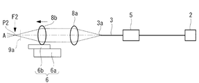
- FIG. 1 is an overall configuration diagram of an optical projection device according to an embodiment of the present invention.
- FIG. 2 is a diagram illustrating a configuration example of a first scanning unit in the optical projection device in FIG. 1.
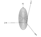
- FIG. 5 is a diagram illustrating a scanning locus of an intermediate spot when the movable lens is stationary.
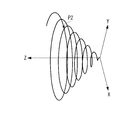
- FIG. 7 is a diagram illustrating a scanning locus of an intermediate spot when the movable lens is moving. It is a figure explaining the positional relationship of a movable lens and an intermediate spot, and is a figure showing the state where a movable lens is arranged at a reference position.
- FIG. 4B is a diagram illustrating a state where the movable lens is displaced from the reference position in FIG. 4A to the ⁇ Z side.
- FIG. 4B is a diagram illustrating a state where the movable lens is displaced from the reference position in FIG. 4A to the ⁇ Z side.
- FIG. 4B is a diagram illustrating a state where the movable lens has been displaced from the reference position in FIG. 4A to the + Z side.
- FIG. 7 is a diagram illustrating a change in an image plane of the relay lens and the objective lens when the movable lens is stationary.
- FIG. 7 is a diagram illustrating a change in an image plane of the relay lens and the objective lens when the movable lens is moving.
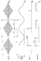
- 2 is a timing chart illustrating an operation of the light projection device in FIG. 1.
- FIG. 3 is a diagram illustrating a non-corrected image plane and a target image plane on the surface of a subject.
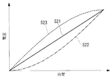
- FIG. 7 is a diagram illustrating a specific example of a second drive signal.
- FIG. 9 is a diagram showing an intermediate image plane formed based on a second drive signal S21 of FIG.
- FIG. 9 is a diagram showing an intermediate image plane formed based on a second drive signal S22 in FIG.
- FIG. 9 is a diagram showing an intermediate image plane formed based on a second drive signal S23 in FIG.
- FIG. 9 is a diagram illustrating an example of a change in a second drive signal due to a user I / F.
- FIG. 9 is a diagram illustrating an example of a change in an intermediate image plane due to a user I / F.
- FIG. 11 is a diagram illustrating another example of the target image plane.
- FIG. 11 is a diagram illustrating another example of the target image plane.
- FIG. 11 is a diagram illustrating another example of the target image plane.
- FIG. 9 is a diagram illustrating a positional relationship between a movable element and an intermediate spot in a modification of the light projection device in FIG.
- FIG. 13B is a diagram showing a state where the intermediate spot is displaced to the ⁇ Z side due to displacement of the movable element from the reference position in FIG. 13A.
- FIG. 13B is a diagram illustrating a state where the movable element is displaced to the intermediate spot + Z side by the displacement of the movable element from the reference position in FIG. 13A.
- FIG. 13 is a diagram illustrating a positional relationship between a movable lens and an intermediate spot in another modification of the light projection device in FIG. 1, and is a diagram illustrating a state where a movable element is arranged at a reference position.
- FIG. 13 is a diagram showing a state where a movable element is arranged at a reference position.
- FIG. 14B is a diagram showing a state where the intermediate spot has been displaced to the ⁇ Z side due to displacement of the movable element from the reference position in FIG. 14A.
- FIG. 14B is a diagram showing a state in which the intermediate spot has been displaced to the + Z side by displacement of the movable element from the reference position in FIG. 14A.
- FIG. 13 is a diagram illustrating a positional relationship between a movable lens and an intermediate spot in another modification of the light projection device in FIG. 1, and is a diagram illustrating a state where a movable element is arranged at a reference position.
- FIG. 15B is a diagram illustrating a state in which the intermediate spot has been displaced to the ⁇ Z side due to displacement of the movable element from the reference position in FIG. 15A.
- FIG. 15B is a diagram showing a state in which the intermediate spot has been displaced to the + Z side by displacement of the movable element from the reference position in FIG. 15A.
- the optical projection device 1 is built in an endoscope 100 as shown in FIG.
- the endoscope 100 includes a hard and long scope 20, a handle 30 connected to a base end of the scope 20, and a controller 40.
- the light projection device 1 includes a light source unit 2, a long optical fiber 3, an imaging optical system 4, a first scanning unit 5, a second scanning unit 6, and a control unit 7. .
- the light source unit 2, the optical fiber 3, and the imaging optical system 4 are arranged in this order from the base end side of the endoscope 100 to the distal end side.
- the light source unit 2 is provided in the handle 30 and includes a laser light source such as a laser diode.
- the laser light L emitted from the laser light source enters the base end of the optical fiber 3.
- the optical fiber 3 is disposed in the handle 30, and the base end of the optical fiber 3 is connected to the light source 2.
- the optical fiber 3 guides the laser light L from the light source unit 2 from the base end to the distal end 3a, and emits the laser light L from the distal end 3a.
- the distal end of the optical fiber 3 is supported in a cantilever shape by a support 5a of a first scanning unit 5 described later.
- the optical axis of the optical fiber 3 in the support portion 5a is defined as "optical axis A", and an XYZ orthogonal coordinate system having the optical axis A as the Z axis is used.
- the + Z direction is the traveling direction of the laser light L (forward of the optical axis A), and the -Z direction is the direction opposite to the traveling direction of the laser light L (back of the optical axis A).
- the X axis and the Y axis are orthogonal to the optical axis A and mutually orthogonal.
- illustration of the support part 5a is abbreviate
- the imaging optical system 4 has the same optical axis as the optical axis A.
- the imaging optical system 4 condenses the laser light L emitted from the tip 3a of the optical fiber 3, and projects the spot P1 of the laser light L on the subject B.
- the imaging optical system 4 includes a light-collecting optical system 8 provided in a handle 30, and a relay lens 9 and an objective lens 10 provided in a scope 20.
- the focusing optical system 8 is disposed between the distal end 3a of the optical fiber 3 and the relay lens 9, and focuses the laser light L from the distal end 3a on the base end 9a of the relay lens 9 or near the base end 9a.
- the condensing optical system 8 includes a pair of lenses 8a and 8b.
- the lens 8a on the side of the optical fiber 3 forms the laser beam L emitted from the tip 3a of the optical fiber 3 into parallel light.
- the lens 8b on the side of the relay lens 9 has a focal point F2 at or near the proximal end 9a of the relay lens 9.
- the lens 8b focuses the laser beam L on the focal point F2 and forms an intermediate spot P2 on the focal point F2.
- the relay lens 9 is a long gradient index (GRIN) lens disposed along the longitudinal direction of the scope 20.
- the relay lens 9 relays the laser light L that has entered the base end 9a from the focusing optical system 8.
- the objective lens 10 is a short GRIN lens arranged along the longitudinal direction of the scope 20, and is arranged at the tip of the scope 20.
- the objective lens 10 is joined to the tip of the relay lens 9, focuses the laser light L emitted from the tip of the relay lens 9, and projects the spot P 1 of the laser light L on the subject B.
- the lens 8b is a movable lens that can move along the optical axis A with respect to the scope 20 and the handle 30.
- the movement of the lens 8b causes the focal point F2 and the intermediate spot P2 to move linearly in the direction along the optical axis A.
- the lenses 8a, 9, and 10 other than the movable lens 8b are fixed to the scope 20 and the handle 30.
- the optical fiber 3 is also fixed to the scope 20 and the handle 30 except for the tip portion vibrated by the first scanning unit 5.
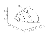
- the first scanning unit 5 moves the tip 3a of the optical fiber 3 around the optical axis A in a spiral shape in the XY plane in accordance with the first drive signals S1_X and S1_Y (see FIG. 6) from the control unit 7. Spiral vibration along the vibration trajectory. Thereby, the laser light L emitted from the tip 3a is spirally scanned along a spiral scanning trajectory around the optical axis A, and the intermediate spot P2 and the spot P1 are also rotated around the optical axis A as shown in FIG. Is scanned spirally.
- FIG. 3A shows a scanning trajectory of the intermediate spot P2.
- the first scanning unit 5 forms an uncorrected image plane I1 (see FIG. 5A) by spirally scanning the spot P1 with the movable lens 8b stationary at a predetermined reference position.
- FIG. 2 is a front view of the optical fiber 3 and the first scanning unit 5 as viewed in the ⁇ Z direction, and shows a configuration example of the first scanning unit 5.
- the first scanning unit 5 is a piezoelectric actuator including a ferrule 11 and piezoelectric elements 12X and 12Y.
- the ferrule 11 is a quadrangular cylindrical member having elasticity.
- the ferrule 11 is fixed to the outer peripheral surface of the optical fiber 3 at a position spaced from the distal end 3a toward the proximal end.
- a support 5 a is fixed to the base end of the ferrule 11, and the support 5 a is fixed to the handle 30.
- the distal end of the optical fiber 3 is supported in a cantilever shape by the support portion 5a.
- Plate-shaped piezoelectric elements 12X and 12Y are fixed to each of the four outer peripheral surfaces of the ferrule 11.
- the two piezoelectric elements 12X facing each other in the X direction expand and contract in the Z direction according to the first drive signal S1_X for the X direction, thereby causing the distal end portion of the optical fiber 3 to bend and vibrate, thereby causing the distal end 3a to move in the X direction.
- the two piezoelectric elements 12Y opposed to each other in the Y direction expand and contract and vibrate in the Z direction according to the first drive signal S1_Y for the Y direction, thereby causing the distal end of the optical fiber 3 to bend and vibrate, thereby causing the distal end 3a to move in the Y direction.
- the phase of the drive signal S1_X and the phase of the drive signal S1_Y are shifted from each other by ⁇ / 2, whereby the tip 3a is caused to spirally vibrate.
- the first scanning unit 5 may be another type of actuator.
- the first scanning unit 5 is an electromagnetic actuator including a cylindrical permanent magnet magnetically attached in the longitudinal direction and having magnetic poles at both ends, and an electromagnetic coil provided at a position facing each magnetic pole of the permanent magnet. It may be.
- the optical fiber 3 is inserted into the permanent magnet so as to protrude from the permanent magnet, and the permanent magnet is fixed to the outer peripheral surface of the optical fiber 3.
- the electromagnetic coil When a current is supplied from the control unit 7 to the electromagnetic coil, the electromagnetic coil generates a magnetic field near the magnetic pole of the permanent magnet, the permanent magnet vibrates, and the optical fiber 3 vibrates.
- FIG. 4A shows a state where the lens 8b is arranged at a reference position where the intermediate spot P2 coincides with the base end 9a of the relay lens 9.
- FIG. 4B shows a state where the lens 8b is displaced in the ⁇ Z direction from the reference position.
- FIG. 4C shows a state where the lens 8b is displaced in the + Z direction from the reference position.
- the second scanning section 6 has a fixed section 6a fixed to the handle 30 and a movable section 6b fixed to the lens 8b, and the movable section 6b moves in the direction along the optical axis A with respect to the fixed section 6a. Can be moved.
- a second scanning unit 6 is an arbitrary element that can move the lens 8b in one axis direction.
- the second scanning unit 6 includes a piezo actuator or a voice coil motor.
- FIG. 5A shows the relationship between the image plane I2 formed by the scanned intermediate spot P2 and the field curvature generated in the relay lens 9 and the objective lens 10.
- An intermediate image plane I2 is formed at or near the base end 9a of the relay lens 9.
- the intermediate image plane I2 is a plane on which the intermediate spot P2 is scanned by the first and second scanning units 5, 6.
- the intermediate image plane I2 becomes a flat plane perpendicular to the optical axis A, as shown in FIGS. 3A and 5A.
- An image transmitted through the relay lens 9 and the objective lens 10, which are GRIN lenses, is gradually added with field curvature.
- the image surface I3 at the tip of the objective lens 10 is a curved surface that is convex on the + Z side (subject B side), and the image surface formed by the scanned spot P1 (non- The (corrected image plane) I1 also becomes a curved surface convex on the + Z side.
- the non-corrected image plane I1 is a plane on which the spot P1 is scanned by the first scanning unit 5 in a state where the lens 8b is stationary at the reference position.
- the control unit 7 generates the first drive signals S1_X, S1_Y and the second drive signal S2, as shown in FIG.
- the control unit 7 supplies the first drive signals S1_X and S1_Y to the first scanning unit 5, and supplies the second drive signal S2 to the second scanning unit 6.
- the first drive signals S1_X and S1_Y are vibration waves whose amplitude envelopes change with time in a constant cycle T in a sinusoidal manner.
- the amplitudes of the first drive signals S1_X and S1_Y correspond to the vibration amplitudes of the tip 3a of the optical fiber 3 in the X and Y directions.
- the first scanning unit 5 spirally scans the spots P1 and P2 radially outward during the first period ⁇ t1 in accordance with the first drive signals S1_X and S1_Y, and performs the first period ⁇ t1.
- the spots P1 and P2 are spirally scanned radially inward.
- the second drive signal S2 is a triangular wave or a sine wave.
- the magnitude of the second drive signal S2 corresponds to the amount of movement of the lens 8b in the + Z direction from the initial position.
- the initial position is a position where the intermediate spot P2 is separated from the base end 9a in the ⁇ Z direction.
- the second drive signal S2 has the same cycle T as the cycle T of the first drive signals S1_X and S1_Y.
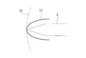
- the control unit 7 controls the first scanning unit 5 and the second scanning unit 6 in synchronization by synchronizing the first driving signals S1_X and S1_Y with the second driving signal S2. At this time, based on the difference between the non-corrected image plane I1 and the target image plane I1 ', the control unit 7 moves the spot P1 spirally scanned by the first scanning unit 5 from the position on the non-corrected image plane I1 to the target.
- the moving direction and the moving amount of the movable lens 8b are controlled by the second drive signal S2 so as to be displaced to the position on the image plane I1 ', whereby the uncorrected image plane I1 is corrected to the target image plane I1'. .
- the target image plane I1 ' is, for example, a plane set in the control unit 7 by a user. This makes it possible to control the image plane on which the spot P1 is scanned to a surface having an arbitrary shape, and to correct the aberration of the illumination light, particularly the curvature of field, according to the shape of the surface of the subject B.
- the moving direction and the moving amount of the lens 8b are calculated from the difference between the known shape of the uncorrected image plane I1 and the shape of the target image plane I1 '.
- the moving direction and the moving amount of the lens 8b may be stored in a storage device (not shown) in advance.
- the control unit 7 sets the amplitudes of the first drive signals S1_X and S1_Y and the amplitude of the second drive signal S2 at the same time, as shown in FIG.
- the first drive signals S1_X, S1_Y and the second drive signal S2 are synchronized so that they become maximum and become minimum at the same time.
- the second scanning unit 6 moves the movable lens 8b in a direction approaching the base end 9a.
- the second scanning unit 6 moves the movable lens 8b in a direction away from the base end 9a.
- the intermediate image plane I2 becomes a curved surface or a conical surface that is convex on the ⁇ Z side, and the curvature of field caused by the lenses 9 and 10 is canceled by the curvature of the intermediate image plane I2.
- the non-corrected image plane I1 is corrected to a flat target image plane I1 '. In this manner, the non-corrected image plane I1 convex toward the subject B is corrected to a flat surface without using a lens having a negative refractive power.
- the control unit 7 includes, for example, a processor, a storage device, a signal generator, and a digital-to-analog (DA) converter (all not shown) incorporated in the controller 40.
- the processor is, for example, a central processing unit, and generates a control signal according to a control program stored in a storage device.
- the control signal is a signal that defines parameters such as frequency, amplitude, and phase of each of the drive signals S1_X, S1_Y, and S2.
- the signal generator generates a digital waveform according to the control signal.
- the DA converter generates drive signals S1_X, S1_Y, and S2, which are analog signals, by performing DA conversion on the digital waveform.
- the laser light L emitted from the light source unit 2 guides the inside of the optical fiber 3, is emitted from the tip 3 a of the optical fiber 3, and The light enters the relay lens 9 via the relay lens 9, is relayed by the relay lens 9, and is focused on the subject B by the objective lens 10.
- the spot P1 of the laser beam L formed on the subject B is spirally scanned around the optical axis A by causing the first scanning section 5 to spirally vibrate the tip 3a of the optical fiber 3.
- the spot P1 is linearly scanned in the direction along the optical axis A by the lens 8b being linearly moved by the second scanning unit 6.
- the spiral scanning by the first scanning unit 5 and the linear scanning by the second scanning unit 6 are executed by the control unit 7 in synchronization with each other so that the spot P1 is linearly scanned during one period of the spiral scanning.
- the non-corrected image plane I1 of the laser beam L illuminating the subject B is corrected to a flat target image plane I1 '. Therefore, it is possible to scan a flat or less uneven surface of the subject B with the small spot P1 of the laser beam L.
- signal light such as fluorescence or reflected light of the laser light L is generated.
- the signal light is detected by a detection optical system (not shown) provided in the scope 20, and information on the intensity of the signal light is transmitted from the detection optical system to the controller 40.
- an image of the subject B is generated by associating the intensity of the signal light with the position of the spot P1 on the scanning trajectory.
- FIG. 6 shows an example in which an image of the subject B is acquired on the outward path of the spiral scan.
- the control unit 7 generates a pulse signal as a photographing trigger at a timing when the drive signals S1_X, S1_Y, and S2 are maximized.
- the detection optical system detects the signal light over an imaging period of a predetermined length in response to the imaging trigger.
- FIG. 7 shows the relationship between the shape of the surface of the subject B and the shapes of the image planes I1 and I1 '.
- the spot diameter of the laser beam L on the surface of the subject B increases, and as a result, , The image is blurred. Image blur becomes more remarkable as the deviation ⁇ between the uncorrected image plane I1 and the surface of the subject B increases.
- the non-corrected image plane I1 is corrected to a flat target image plane I1 'according to the surface shape of the subject B that is flat or has little unevenness. Therefore, there is an advantage that an image in which the entire surface of the subject B is in focus can be obtained.
- the large curvature of field generated by the GRIN lenses 9 and 10 can be easily corrected by simple means simply moving the lens 8b other than the GRIN lenses 9 and 10 linearly.
- the non-corrected image plane I1 has a spread of 0.26 mm in the direction along the optical axis A due to field curvature. Even such a large curvature of field, which is difficult to correct using the refractive power of the lens, can be easily corrected by moving the movable lens 8b.
- the tip 3a of the optical fiber 3 has a vibration period of about 0.1 ms. Is required.
- the lens 8b only needs to make one reciprocation within 16.7 ms. It is easy to realize such mechanical movement of the lens 8b.
- the curvature of field caused by the INGRIN lenses 9 and 10 can also be corrected by arranging a concave lens having a negative refractive power at the distal end of the scope 20.
- a concave lens having a negative refractive power at the distal end of the scope 20.
- FIG. 8 shows a specific example of the second drive signal S2
- FIGS. 9A to 9C show specific examples of the scanning trajectory of the intermediate spot P2, that is, the intermediate image plane I2.
- a second drive signal S21 for moving the lens 8b at a constant speed a second drive signal S22 for gradually increasing the movement speed of the lens 8b, and a second drive signal S22 for gradually decreasing the movement speed of the lens 8b.
- the drive signal S23 is shown.
- the intermediate image plane I2 formed according to the second drive signal S21 has a conical shape as shown in FIG. 9A.
- the intermediate image plane I2 formed according to the second drive signal S22 has a substantially conical shape with a concave side surface.
- the intermediate image plane I2 formed in accordance with the second drive signal S23 has a substantially conical shape with a convex side surface, as shown in FIG. 9C.
- the specific waveform shape of the second drive signal S2 can be variously set according to the curvature of field generated by the lenses 9 and 10.
- the user wants to change the target image plane I1 'while observing the subject B.
- the shape of the surface of the subject B in the observation range may differ depending on the position in the body cavity.
- a user interface (I / F) 13 for the user to change the shape of the intermediate image plane I2 may be provided.
- the user I / F 13 may be provided in the controller 40.
- the user I / F 13 is a dial provided on the handle 30.
- the second drive signal S2 can be continuously changed between two patterns 1 and 2 having different amplitudes by the operation of the user I / F 13 by the user, as shown in FIG.
- the size of the intermediate image plane I2 in the direction along the optical axis A is changed according to the change in the amplitude of the second drive signal S2.
- the user I / F 13 may be configured to be able to change the moving speed of the movable lens 8b.
- the target image plane I1 ' is not limited to a flat surface, but can be set to an arbitrary shape according to the shape of the surface of the subject B.
- 12A and 12B show another example of the target image plane I1 '.
- the target image plane I1 ′ shown in FIG. 12A is a curved surface that is larger on the + Z side and has a larger curvature than the uncorrected image plane I1.
- Such a target image plane I1 ' is advantageous in that, for example, when observing a narrow cavity, it is possible to obtain an image whose focus is not only on the front but also on the inner surface of the cavity.
- control unit 7 moves the movable lens 8b in the direction away from the base end 9a by the second scanning unit 6 during the first period ⁇ t1 in order to form the intermediate image plane I2 convex on the + Z side. Then, the movable lens 8b is moved by the second scanning unit 6 in a direction approaching the base end 9a during the second period ⁇ t2.
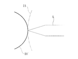
- the target image plane I1 ′ shown in FIG. 12B is a curved surface that is convex on the ⁇ Z side.
- a target image plane I1 ' is advantageous in that, for example, when observing the surface of the raised subject B, the entire subject B can be observed without blurring.
- the control section 7 moves the lens 8b by the second scanning section 6 so that the intermediate image plane I2 is further convexed on the ⁇ Z side than the intermediate image plane I2 shown in FIG. 5B.
- the movable element moved by the second scanning unit 6 is only one lens 8b, but the movable element can move the intermediate spot P2 along the optical axis A.
- the second scanning unit 6 supports the condensing optical system 8 and the first scanning unit 5.
- the second scanning unit 6 moves the light collecting optical system 8 and the distal end of the optical fiber 3 integrally along the optical axis A while maintaining the relative positions of the light collecting optical system 8 and the distal end of the optical fiber 3. Move.
- the tip of the optical fiber 3 is a movable element.
- the second scanning unit 6 supports the first scanning unit 5 and moves the first scanning unit 5 and the distal end of the optical fiber 3 integrally along the optical axis A.
- the intermediate spot P2 moves to the + Z side. Therefore, when forming the intermediate image plane I2 convex on the ⁇ Z side, the control unit 7 controls the second scanning unit 6 to move the distal end of the optical fiber 3 closer to the base end 9a during the first period ⁇ t1.
- the second scanning unit 6 moves the distal end of the optical fiber 3 away from the base end 9a during the second period ⁇ t2.
- the second scanning unit 6 supports the lens 8a and the first scanning unit 5.
- the second scanning unit 6 moves the tip of the lens 8a and the tip of the optical fiber 3 along the optical axis A in a direction in which the lens 8a approaches and separates from each other, and moves between the tip 3a of the optical fiber 3 and the lens 8a. Change the distance.
- the second scanning unit 6 is an element such as a piezo actuator that can expand and contract in the direction along the optical axis A.
- the second scanning unit 6 may include two elements that respectively move the first scanning unit 5 and the lens 8a.
- the control unit 7 moves the distal end of the optical fiber 3 to the + Z side by the second scanning unit 6 during the first period ⁇ t1.
- the lens 8a is moved to the ⁇ Z side, and the tip of the optical fiber 3 is moved to the ⁇ Z side and the lens 8a is moved to the + Z side by the second scanning unit 6 during the second period ⁇ t2.
- the condensing optical system 8 is an optical system including a pair of lenses.
- the specific configuration of the condensing optical system 8 is not limited to this, and a combination of three or more lenses is used.
- the lens as the movable element does not necessarily need to be a lens located at the end of the condensing optical system 8, and the position of the lens as the movable element can be freely selected by the practitioner of the present invention. .
- Objective lens imaging optical system, gradient index lens
- Ferrule Ferrule
- User interface 20 Scope 30 Handle 40 Controller 100 Endoscope A Optical axis B Subject I1 Uncorrected image plane I1 'Target image plane I2 Intermediate image plane P1 Spot P2 Intermediate spot
Landscapes
- Physics & Mathematics (AREA)
- Health & Medical Sciences (AREA)
- Life Sciences & Earth Sciences (AREA)
- Optics & Photonics (AREA)
- Surgery (AREA)
- General Physics & Mathematics (AREA)
- Biomedical Technology (AREA)
- General Health & Medical Sciences (AREA)
- Pathology (AREA)
- Engineering & Computer Science (AREA)
- Nuclear Medicine, Radiotherapy & Molecular Imaging (AREA)
- Heart & Thoracic Surgery (AREA)
- Medical Informatics (AREA)
- Molecular Biology (AREA)
- Animal Behavior & Ethology (AREA)
- Radiology & Medical Imaging (AREA)
- Public Health (AREA)
- Veterinary Medicine (AREA)
- Biophysics (AREA)
- Astronomy & Astrophysics (AREA)
- Mechanical Optical Scanning Systems (AREA)
- Endoscopes (AREA)
- Instruments For Viewing The Inside Of Hollow Bodies (AREA)
Abstract
光投影装置(1)は、光源部(2)と、光源部(2)からのレーザ光(L)を先端(3a)から射出する光ファイバ(3)と、先端(3a)をスパイラル振動させることによって、レーザ光(L)のスポット(P1)を被写体(B)上でスパイラル走査する第1の走査部(5)と、先端(3a)からのレーザ光(L)のスポット(P1)を被写体(B)に投影する結像光学系(4)と、光ファイバ(3)の先端部および結像光学系(4)のうち少なくとも一部を光軸(A)に沿う方向に移動させることによってスポット(P1)を光軸(A)に沿う方向に直線走査する第2の走査部(6)と、第1および第2の走査部(5,6)を同期させて制御することによってスポット(P1)をスパイラル走査の1周期の間に直線走査させる制御部(7)とを備える。
Description
本発明は、光投影装置および光投影方法に関するものである。
従来、光ファイバの先端を振動させることによって、光ファイバから被写体に照射される光を走査する内視鏡用の光ファイバスキャナが知られている(例えば、特許文献1参照。)。
特許文献1において、光ファイバの先端から射出された光は、レンズを経由して被写体に照射される。したがって、被写体に照射される光には、レンズに起因する像面湾曲等の収差が発生する。診断または治療には鮮鋭な被写体の内視鏡画像が必要であり、そのためには、被写体面の形状に応じて収差を補正する必要がある。しかしながら、特許文献1は、収差、特に像面湾曲を適切に補正することができないという問題がある。
本発明は、上述した事情に鑑みてなされたものであって、被写体を照明する照明光の収差を被写体面の形状に応じて補正することができる光投影装置および光投影方法を提供することを目的とする。
本発明の一態様は、レーザ光を発する光源部と、該光源部から発せられた前記レーザ光を導光し、先端から射出する光ファイバと、前記光ファイバの先端部を片持ち梁状に支持する支持部を有し、該支持部における前記光ファイバの光軸を軸にして前記光ファイバの先端をスパイラル振動させることによって、前記レーザ光のスポットを被写体上でスパイラル走査する第1の走査部と、前記支持部における前記光ファイバの光軸と同一の光軸を有し、前記光ファイバの先端から射出された前記レーザ光を集光させ、前記レーザ光のスポットを前記被写体に投影する結像光学系と、前記光ファイバの先端部および前記結像光学系のうち少なくとも一部を前記支持部における前記光ファイバの光軸に沿う方向に移動させることによって前記スポットを前記支持部における前記光ファイバの光軸に沿う方向に直線走査する第2の走査部と、前記第1の走査部および前記第2の走査部を同期させて制御することによって前記スポットを前記スパイラル走査の1周期の間に直線走査させる制御部とを備える光投影装置である。
本発明の他の態様は、光ファイバの先端から射出されたレーザ光を集光させ、該レーザ光のスポットを被写体に投影する光投影方法であって、前記光ファイバの先端部を片持ち梁状に支持する支持部における前記光ファイバの光軸を軸にして前記光ファイバの先端をスパイラル振動させることによって、前記スポットをスパイラル走査するステップと、前記スポットを前記光軸に沿う方向に直線走査するステップとを含み、前記スパイラル走査するステップと前記直線走査するステップとを同期させて実行することによって前記スポットをスパイラル走査の1周期の間に直線走査させる光投影方法である。
本発明によれば、被写体を照明する照明光の収差を被写体面の形状に応じて補正することができるという効果を奏する。
以下に、本発明の一実施形態に係る光投影装置1および光投影方法について図面を参照して説明する。
本実施形態に係る光投影装置1は、図1に示されるように、内視鏡100に内蔵される。内視鏡100は、硬質で長尺のスコープ20と、スコープ20の基端に接続されるハンドル30と、コントローラ40とを備えている。
光投影装置1は、光源部2と、長尺の光ファイバ3と、結像光学系4と、第1の走査部5と、第2の走査部6と、制御部7とを備えている。
本実施形態に係る光投影装置1は、図1に示されるように、内視鏡100に内蔵される。内視鏡100は、硬質で長尺のスコープ20と、スコープ20の基端に接続されるハンドル30と、コントローラ40とを備えている。
光投影装置1は、光源部2と、長尺の光ファイバ3と、結像光学系4と、第1の走査部5と、第2の走査部6と、制御部7とを備えている。
光源部2、光ファイバ3および結像光学系4は、内視鏡100の基端側から先端側に向かって順に配置されている。
光源部2は、ハンドル30内に設けられており、レーザダイオードのようなレーザ光源を備えている。レーザ光源が発したレーザ光Lは、光ファイバ3の基端に入射する。
光源部2は、ハンドル30内に設けられており、レーザダイオードのようなレーザ光源を備えている。レーザ光源が発したレーザ光Lは、光ファイバ3の基端に入射する。
光ファイバ3はハンドル30内に配置され、光ファイバ3の基端は光源部2に接続されている。光ファイバ3は、光源部2からのレーザ光Lを基端から先端3aまで導光し、先端3aからレーザ光Lを射出する。光ファイバ3の先端部は、後述する第1の走査部5の支持部5aによって片持ち梁状に支持されている。以下の説明において、支持部5aにおける光ファイバ3の光軸を「光軸A」と定義し、光軸AをZ軸とするXYZ直交座標系を用いる。+Z方向は、レーザ光Lの進行方向(光軸Aの前方)であり、-Z方向は、レーザ光Lの進行方向とは逆方向(光軸Aの後方)である。X軸およびY軸は、光軸Aに直交し、かつ、相互に直交している。なお、図1および図2以外の図面において、支持部5aの図示は省略されている。
結像光学系4は、光軸Aと同一の光軸を有している。結像光学系4は、光ファイバ3の先端3aから射出されたレーザ光Lを集光させ、レーザ光LのスポットP1を被写体Bに投影する。具体的には、結像光学系4は、ハンドル30内に設けられた集光光学系8と、スコープ20内に設けられたリレーレンズ9および対物レンズ10と、を備えている。
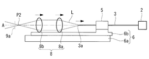
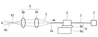
集光光学系8は、光ファイバ3の先端3aとリレーレンズ9との間に配置され、先端3aからのレーザ光Lを、リレーレンズ9の基端9aまたは基端9a近傍に集光させる。具体的には、集光光学系8は、一対のレンズ8a,8bを備える。光ファイバ3側のレンズ8aは、光ファイバ3の先端3aから射出されたレーザ光Lを平行光に形成する。リレーレンズ9側のレンズ8bは、リレーレンズ9の基端9aまたは基端9aの近傍に焦点F2を有している。レンズ8bは、焦点F2にレーザ光Lを集光させ、焦点F2に中間スポットP2を形成する。
リレーレンズ9は、スコープ20の長手方向に沿って配置された長尺の屈折率分布型(GRIN)レンズである。リレーレンズ9は、集光光学系8から基端9aに入射したレーザ光Lをリレーする。
対物レンズ10は、スコープ20の長手方向に沿って配置された短尺のGRINレンズであり、スコープ20の先端に配置されている。対物レンズ10は、リレーレンズ9の先端に接合されており、リレーレンズ9の先端から射出されたレーザ光Lを集光させ、レーザ光LのスポットP1を被写体Bに投影する。
対物レンズ10は、スコープ20の長手方向に沿って配置された短尺のGRINレンズであり、スコープ20の先端に配置されている。対物レンズ10は、リレーレンズ9の先端に接合されており、リレーレンズ9の先端から射出されたレーザ光Lを集光させ、レーザ光LのスポットP1を被写体Bに投影する。
レンズ8bは、スコープ20およびハンドル30に対して光軸Aに沿って移動可能である可動レンズである。レンズ8bの移動によって、焦点F2および中間スポットP2が光軸Aに沿う方向に直線移動する。
可動レンズ8b以外のレンズ8a,9,10は、スコープ20およびハンドル30に対して固定されている。光ファイバ3も、第1の走査部5によって振動させられる先端部を除いて、スコープ20およびハンドル30に対して固定されている。
可動レンズ8b以外のレンズ8a,9,10は、スコープ20およびハンドル30に対して固定されている。光ファイバ3も、第1の走査部5によって振動させられる先端部を除いて、スコープ20およびハンドル30に対して固定されている。
第1の走査部5は、制御部7からの第1の駆動信号S1_X,S1_Y(図6参照。)に従って、光軸Aを軸にして光ファイバ3の先端3aをXY平面内でスパイラル状の振動軌跡に沿ってスパイラル振動させる。これにより、先端3aから射出されるレーザ光Lは、光軸A回りのスパイラル状の走査軌跡に沿ってスパイラル走査され、図3Aに示されるように、中間スポットP2およびスポットP1も光軸A回りにスパイラル走査される。図3Aは、中間スポットP2の走査軌跡を示している。第1の走査部5は、可動レンズ8bが所定の基準位置に静止した状態でスポットP1をスパイラル走査することによって非補正像面I1(図5A参照。)を形成する。
図2は、-Z方向に見た光ファイバ3および第1の走査部5の正面図であり、第1の走査部5の構成例を示している。第1の走査部5は、フェルール11と圧電素子12X,12Yとを備える圧電式のアクチュエータである。フェルール11は、弾性を有する四角筒状の部材である。フェルール11は、先端3aから基端側に間隔を空けた位置において光ファイバ3の外周面に固定されている。フェルール11の基端部には支持部5aが固定され、支持部5aはハンドル30に対して固定されている。支持部5aによって光ファイバ3の先端部が片持ち梁状に支持されている。フェルール11の4個の外周面の各々に平板状の圧電素子12X,12Yが固定されている。
X方向に相互に対向する2枚の圧電素子12Xは、X方向用の第1の駆動信号S1_Xに従ってZ方向に伸縮振動することによって、光ファイバ3の先端部を屈曲振動させ、先端3aをX方向に振動させる。Y方向に相互に対向する2枚の圧電素子12Yは、Y方向用の第1の駆動信号S1_Yに従ってZ方向に伸縮振動することによって、光ファイバ3の先端部を屈曲振動させ、先端3aをY方向に振動させる。駆動信号S1_Xの位相と駆動信号S1_Yの位相は、相互にπ/2だけずれており、これにより、先端3aがスパイラル振動させられる。
第1の走査部5は、他の方式のアクチュエータであってもよい。例えば、第1の走査部5は、長手方向に磁着され両端に磁極を有する筒状の永久磁石と、永久磁石の各磁極に対向する位置に設けられた電磁コイルとを備える電磁式のアクチュエータであってもよい。永久磁石内には、光ファイバ3が永久磁石から突出するように挿入され、光ファイバ3の外周面に永久磁石が固定される。制御部7から電磁コイルに電流が供給されることによって、電磁コイルが永久磁石の磁極の近傍に磁場を発生させて永久磁石が振動し、光ファイバ3が振動するようになっている。
第2の走査部6は、制御部7からの第2の駆動信号S2(図6参照。)に従ってレンズ8bを光軸Aに沿って直線移動させる。これにより、図4Aから図4Cに示されるように、中間スポットP2が光軸Aに沿う方向に直線走査され、中間スポットP2に追従してスポットP1も光軸Aに沿う方向に直線走査される。図4Aは、中間スポットP2がリレーレンズ9の基端9aに一致する基準位置にレンズ8bが配置されている状態を示している。図4Bは、レンズ8bが、基準位置から-Z方向に変位した状態を示している。図4Cは、レンズ8bが、基準位置から+Z方向に変位した状態を示している。
第2の走査部6は、ハンドル30に固定される固定部6aと、レンズ8bに固定される可動部6bとを有し、可動部6bが固定部6aに対して光軸Aに沿う方向に移動可能である。このような第2の走査部6は、レンズ8bを1軸方向に移動させることができる任意の素子である。例えば、第2の走査部6は、ピエゾアクチュエータまたはボイスコイルモータを備える。
図5Aは、走査される中間スポットP2によって形成される像面I2と、リレーレンズ9および対物レンズ10において発生する像面湾曲との関係を示している。
リレーレンズ9の基端9aまたは基端9aの近傍には、中間像面I2が形成される。中間像面I2は、第1および第2の走査部5,6によって中間スポットP2が走査される面である。レンズ8bが静止している場合、中間像面I2は、図3Aおよび図5Aに示されるように、光軸Aに垂直な平坦面になる。GRINレンズであるリレーレンズ9および対物レンズ10内を伝送される像には、像面湾曲が徐々に加算される。したがって、中間像面I2が平坦面である場合、対物レンズ10の先端における像面I3は+Z側(被写体B側)に凸の曲面になり、走査されるスポットP1によって形成される像面(非補正像面)I1も、+Z側に凸の曲面になる。非補正像面I1は、レンズ8bが基準位置に静止した状態で第1の走査部5によってスポットP1が走査される面である。
リレーレンズ9の基端9aまたは基端9aの近傍には、中間像面I2が形成される。中間像面I2は、第1および第2の走査部5,6によって中間スポットP2が走査される面である。レンズ8bが静止している場合、中間像面I2は、図3Aおよび図5Aに示されるように、光軸Aに垂直な平坦面になる。GRINレンズであるリレーレンズ9および対物レンズ10内を伝送される像には、像面湾曲が徐々に加算される。したがって、中間像面I2が平坦面である場合、対物レンズ10の先端における像面I3は+Z側(被写体B側)に凸の曲面になり、走査されるスポットP1によって形成される像面(非補正像面)I1も、+Z側に凸の曲面になる。非補正像面I1は、レンズ8bが基準位置に静止した状態で第1の走査部5によってスポットP1が走査される面である。
制御部7は、図6に示されるように、第1の駆動信号S1_X,S1_Yおよび第2の駆動信号S2を生成する。制御部7は、第1の駆動信号S1_X,S1_Yを第1の走査部5に供給し、第2の駆動信号S2を第2の走査部6に供給する。
第1の駆動信号S1_X,S1_Yは、振幅包絡線が一定の周期Tで正弦波状に時間変化する振動波である。第1の駆動信号S1_X,S1_Yの振幅が、光ファイバ3の先端3aのX方向およびY方向の振動振幅に相当する。第1の走査部5は、このような第1の駆動信号S1_X,S1_Yに従って、第1の期間Δt1中にスポットP1,P2を径方向外方に向かってスパイラル走査し、第1の期間Δt1に続く第2の期間Δt2中にスポットP1,P2を径方向内方に向かってスパイラル走査する。
第2の駆動信号S2は、三角波または正弦波である。第2の駆動信号S2の大きさが、レンズ8bの初期位置からの+Z方向の移動量に相当する。初期位置は、中間スポットP2が、基端9aから-Z方向に離間した位置である。第2の駆動信号S2は、第1の駆動信号S1_X,S1_Yの周期Tと同一の周期Tを有する。
制御部7は、第1の駆動信号S1_X,S1_Yと第2の駆動信号S2とを同期させることによって第1の走査部5と第2の走査部6とを同期させて制御する。このときに、制御部7は、非補正像面I1と目標像面I1’との差に基づき、第1の走査部5によってスパイラル走査されるスポットP1を非補正像面I1上の位置から目標像面I1’上の位置に変位させるように、第2の駆動信号S2によって可動レンズ8bの移動方向および移動量を制御し、それにより、非補正像面I1を目標像面I1’に補正する。目標像面I1’は、例えば、ユーザによって制御部7に設定された面である。これにより、スポットP1が走査される像面を任意の形状の面に制御し、照明光の収差、特に像面湾曲を被写体Bの表面の形状に応じて補正することができる。レンズ8bの移動方向および移動量は、既知の非補正像面I1の形状と目標像面I1’の形状との差分から算出される。あるいは、レンズ8bの移動方向および移動量が、図示しない記憶装置に予め記憶されていてもよい。
例えば、目標像面I1’が平坦面である場合、制御部7は、図6に示されるように、第1の駆動信号S1_X,S1_Yの振幅および第2の駆動信号S2の振幅が同一時刻に最大となり、同一時刻に最小となるように、第1の駆動信号S1_X,S1_Yと第2の駆動信号S2とを同期させる。これにより、スポットP1,P2が径方向外方に向かってスパイラル走査される第1の期間Δt1中に、第2の走査部6は可動レンズ8bを基端9aに近接する方向に移動させる。また、スポットP1,P2が径方向内方に向かってスパイラル走査される第2の期間Δt2中に、第2の走査部6は可動レンズ8bを基端9aから離間する方向に移動させる。その結果、図3Bおよび図5Bに示されるように、中間像面I2が-Z側に凸の曲面または円錐面になり、レンズ9,10による像面湾曲が中間像面I2の湾曲によって相殺され、非補正像面I1は平坦な目標像面I1’に補正される。このように、被写体B側に凸の非補正像面I1が、負の屈折力を有するレンズを使用することなく、平坦面に補正される。
このような制御部7は、例えば、コントローラ40に内蔵されたプロセッサ、記憶装置、信号発生器、およびデジタルアナログ(DA)変換器(いずれも図示略。)を備える。プロセッサは、例えば中央演算処理装置であり、記憶装置に記憶された制御プログラムに従って制御信号を生成する。制御信号は、駆動信号S1_X,S1_Y,S2の各々の周波数、振幅および位相等のパラメータを規定する信号である。信号発生器は、制御信号に従ってデジタル波形を発生させる。DA変換器は、デジタル波形をDA変換することによって、アナログ信号である駆動信号S1_X,S1_Y,S2を生成する。
次に、光投影装置1による光投影方法について説明する。
本実施形態に係る光投影装置1によれば、光源部2から発せられたレーザ光Lは、光ファイバ3内を導光し、光ファイバ3の先端3aから射出され、集光光学系8を経由してリレーレンズ9に入射し、リレーレンズ9によってリレーされ、対物レンズ10によって被写体B上に集光させられる。
本実施形態に係る光投影装置1によれば、光源部2から発せられたレーザ光Lは、光ファイバ3内を導光し、光ファイバ3の先端3aから射出され、集光光学系8を経由してリレーレンズ9に入射し、リレーレンズ9によってリレーされ、対物レンズ10によって被写体B上に集光させられる。
被写体B上に形成されたレーザ光LのスポットP1は、光ファイバ3の先端3aが第1の走査部5によってスパイラル振動させられることで、光軸A回りにスパイラル走査される。また、スポットP1は、レンズ8bが第2の走査部6によって直線移動させられることで、光軸Aに沿う方向に直線走査される。スポットP1がスパイラル走査の1周期の間に直線走査されるように、第1の走査部5によるスパイラル走査と第2の走査部6による直線走査は、制御部7によって相互に同期して実行される。これにより、被写体Bを照明するレーザ光Lの非補正像面I1は平坦な目標像面I1’に補正される。したがって、平坦な、または凹凸の少ない被写体Bの表面をレーザ光Lの小さなスポットP1で走査することができる。
被写体B上のスポットP1の位置では、蛍光またはレーザ光Lの反射光のような信号光が発生する。信号光は、スコープ20に設けられた検出光学系(図示略)によって検出され、検出光学系からコントローラ40に信号光の強度の情報が送信される。コントローラ40において、信号光の強度が走査軌跡上のスポットP1の位置と対応付けられることによって、被写体Bの画像が生成される。図6には、スパイラル走査の往路において被写体Bの画像を取得する例が示されている。制御部7は、駆動信号S1_X,S1_Y,S2が最大となるタイミングで、撮影トリガであるパルス信号を発生させる。検出光学系は、撮影トリガに応答して、所定の長さの撮影期間にわたって信号光を検出する。
図7は、被写体Bの表面の形状と像面I1,I1’の形状との関係を示している。図7に示されるように、非補正像面I1の形状と被写体Bの表面の形状との間にずれが存在している場合、被写体Bの表面におけるレーザ光Lのスポット径が広がり、その結果、画像にぼけが生じる。画像のぼけは、非補正像面I1と被写体Bの表面との間のずれδが大きい程、顕著になる。
本実施形態によれば、平坦なまたは凹凸の少ない被写体Bの表面形状に応じて、非補正像面I1が平坦な目標像面I1’に補正される。したがって、全体にわたって被写体Bの表面に焦点が合った画像を取得することができるという利点がある。
本実施形態によれば、平坦なまたは凹凸の少ない被写体Bの表面形状に応じて、非補正像面I1が平坦な目標像面I1’に補正される。したがって、全体にわたって被写体Bの表面に焦点が合った画像を取得することができるという利点がある。
また、本実施形態によれば、GRINレンズ9,10が発生させる大きな像面湾曲を、GRINレンズ9,10以外のレンズ8bを直線移動させるだけの簡易な手段によって容易に補正することができるという利点がある。例えば、図5Aに示されるように、GRINレンズ9,10の一設計例において、非補正像面I1は、像面湾曲によって、光軸Aに沿う方向に0.26mmの広がりを有する。このような、レンズの屈折力を利用した補正が困難な大きな像面湾曲であっても、可動レンズ8bの移動によって容易に補正することができる。
例えば、スパイラル状の走査軌跡の周回数が180周である場合、観察範囲の1枚の画像を16.7msで取得するために、光ファイバ3の先端3aには、0.1ms程度の振動周期が要求される。一方、レンズ8bは、16.7msの間に一往復すればよい。このようなレンズ8bの機械的な移動の実現は容易である。
例えば、スパイラル状の走査軌跡の周回数が180周である場合、観察範囲の1枚の画像を16.7msで取得するために、光ファイバ3の先端3aには、0.1ms程度の振動周期が要求される。一方、レンズ8bは、16.7msの間に一往復すればよい。このようなレンズ8bの機械的な移動の実現は容易である。
GRINレンズ9,10による像面湾曲は、負の屈折力を有する凹レンズをスコープ20の先端に配置することによっても、補正することができる。ただし、極細のスコープ20の場合、凹レンズをスコープ20の先端に配置することが困難である。本実施形態によれば、ハンドル30内の光学素子8aの移動によって像面湾曲を補正するので、極細のスコープ20にも好適に適用することができるという利点がある。
図8は、第2の駆動信号S2の具体例を示し、図9Aから図9Cは、中間スポットP2の走査軌跡、すなわち中間像面I2の具体例を示している。
図8において、レンズ8bを一定の速度で移動させる第2の駆動信号S21と、レンズ8bの移動速度を次第に増大させる第2の駆動信号S22と、レンズ8bの移動速度を次第に低下させる第2の駆動信号S23が示されている。
図8において、レンズ8bを一定の速度で移動させる第2の駆動信号S21と、レンズ8bの移動速度を次第に増大させる第2の駆動信号S22と、レンズ8bの移動速度を次第に低下させる第2の駆動信号S23が示されている。
第2の駆動信号S21に従って形成される中間像面I2は、図9Aに示されるように、円錐形である。第2の駆動信号S22に従って形成される中間像面I2は、図9Bに示されるように、側面が凹状の略円錐形である。第2の駆動信号S23に従って形成される中間像面I2は、図9Cに示されるように、側面が凸状の略円錐形である。このように、第2の駆動信号S2の具体的な波形形状は、レンズ9,10によって発生する像面湾曲に応じて様々に設定することができる。
被写体Bの観察中に、目標像面I1’を変化させたいことがある。例えば、体腔内の観察において、観察範囲の被写体Bの表面の形状が体腔内の位置によって異なることがある。このような場合のために、ユーザが中間像面I2の形状を変化させるためのユーザインタフェース(I/F)13が設けられていてもよい。ユーザI/F13は、コントローラ40に設けられていてもよい。あるいは、ユーザI/F13は、ハンドル30に設けられたダイヤルである。
例えば、ユーザによるユーザI/F13の操作によって、図10に示されるように、第2の駆動信号S2が、振幅が異なる2つのパターン1,2の間で連続的に変更可能であり、図11に示されるように、第2の駆動信号S2の振幅の変更に従って光軸Aに沿う方向の中間像面I2の寸法が変更される。図8に示されるように、ユーザI/F13は、可動レンズ8bの移動速度を変更することができるように構成されていてもよい。
本実施形態において、目標像面I1’は、平坦面に限定されるものではなく、被写体Bの表面の形状に応じて任意の形状に設定することができる。
図12Aおよび図12Bは、目標像面I1’の他の例を示している。
図12Aに示される目標像面I1’は、非補正像面I1よりも大きな曲率を有する+Z側に凸の曲面である。このような目標像面I1’は、例えば、細い空洞内の観察において、焦点が正面のみならず空洞の内面にも合った画像を得ることができる点で、有利である。この場合、+Z側に凸の中間像面I2を形成するために、制御部7は、第1の期間Δt1中に第2の走査部6によって可動レンズ8bを基端9aから離間する方向に移動させ、第2の期間Δt2中に可動レンズ8bを第2の走査部6によって基端9aに近接する方向に移動させる。
図12Aおよび図12Bは、目標像面I1’の他の例を示している。
図12Aに示される目標像面I1’は、非補正像面I1よりも大きな曲率を有する+Z側に凸の曲面である。このような目標像面I1’は、例えば、細い空洞内の観察において、焦点が正面のみならず空洞の内面にも合った画像を得ることができる点で、有利である。この場合、+Z側に凸の中間像面I2を形成するために、制御部7は、第1の期間Δt1中に第2の走査部6によって可動レンズ8bを基端9aから離間する方向に移動させ、第2の期間Δt2中に可動レンズ8bを第2の走査部6によって基端9aに近接する方向に移動させる。
図12Bに示される目標像面I1’は、-Z側に凸の曲面である。このような目標像面I1’は、例えば、盛り上がった被写体Bの表面の観察において、被写体B全体をボケなく観察することができる点において、有利である。さらに、レーザ光Lによる患部の焼灼または結石の破壊等の治療において、患部である被写体Bにレーザ光Lを均一の強度で照射することができる、あるいは、一定以上のエネルギー密度を担保することができる点で有利である。
この場合、中間像面I2が、図5Bに示される中間像面I2よりも-Z側にさらに凸となるように、制御部7は、第2の走査部6によってレンズ8bを移動させる。
この場合、中間像面I2が、図5Bに示される中間像面I2よりも-Z側にさらに凸となるように、制御部7は、第2の走査部6によってレンズ8bを移動させる。
本実施形態においては、第2の走査部6によって移動させられる可動素子が、一方のレンズ8bのみであることとしたが、可動素子は、中間スポットP2を光軸Aに沿って移動させることができる任意の素子であってよい。具体的には、リレーレンズ9と第1の走査部5との間に配置された素子、すなわち光ファイバ3の先端部および集光光学系8のレンズ8a,8bの中から1つ以上を可動素子として選択することができる。
図13Aから図15Cは、可動素子の他の例を示している。
図13Aから図15Cは、可動素子の他の例を示している。
図13Aから図13Cにおいて、集光光学系8の全てのレンズ8a,8bおよび光ファイバ3の先端部が可動素子である。第2の走査部6は、集光光学系8および第1の走査部5を支持している。第2の走査部6は、集光光学系8および光ファイバ3の先端部の相対位置を維持しながら、集光光学系8および光ファイバ3の先端部を一体的に光軸Aに沿って移動させる。
図14Aから図14Cにおいて、光ファイバ3の先端部が可動素子である。第2の走査部6は、第1の走査部5を支持し、第1の走査部5および光ファイバ3の先端部を一体的に光軸Aに沿って移動させる。光ファイバ3の先端3aが基端9aに近接するにつれて中間スポットP2は+Z側に移動する。したがって、-Z側に凸の中間像面I2を形成する場合、制御部7は、第1の期間Δt1中に第2の走査部6によって光ファイバ3の先端部を基端9aに近接する方向に移動させ、第2の期間Δt2中に第2の走査部6によって光ファイバ3の先端部を基端9aから離間する方向に移動させる。
図15Aから図15Cにおいて、集光光学系8の光ファイバ3側のレンズ8aおよび光ファイバ3の先端部が可動素子である。第2の走査部6は、レンズ8aおよび第1の走査部5を支持している。第2の走査部6は、レンズ8aおよび光ファイバ3の先端部を相互に近接する方向および離間する方向に光軸Aに沿って移動させ、光ファイバ3の先端3aとレンズ8aとの間の距離を変化させる。このような第2の走査部6は、ピエゾアクチュエータのような、光軸Aに沿う方向に伸縮可能な素子である。第2の走査部6は、第1の走査部5およびレンズ8aをそれぞれ移動させる2つの素子を備えていてもよい。
光ファイバ3の先端3aおよびレンズ8aが相互に離間する方向に移動したときに、中間スポットP2は-Z側に移動する。したがって、-Z側に凸の中間像面I2を形成する場合、制御部7は、第1の期間Δt1中に第2の走査部6によって、光ファイバ3の先端部を+Z側に移動させるとともにレンズ8aを-Z側に移動させ、第2の期間Δt2中に第2の走査部6によって、光ファイバ3の先端部を-Z側に移動させるとともにレンズ8aを+Z側に移動させる。
ここまで、本発明を実施するための形態を説明してきたが、本発明は上述した実施の形態のみに限定されるべきものではなく、本発明の要旨を逸脱しない範囲の設計変更等も含まれる。
例えば、上述した実施形態において、集光光学系8は一対のレンズからなる光学系であったが、集光光学系8の具体的な構成はこれに限定されず、3枚以上のレンズの組み合わせから集光光学系8を構成することが可能である。可動素子としてのレンズは、必ずしも集光光学系8の端に位置するレンズである必要はなく、いずれの位置のレンズを可動素子とするかは本発明の実施者が自由に選択することができる。
例えば、上述した実施形態において、集光光学系8は一対のレンズからなる光学系であったが、集光光学系8の具体的な構成はこれに限定されず、3枚以上のレンズの組み合わせから集光光学系8を構成することが可能である。可動素子としてのレンズは、必ずしも集光光学系8の端に位置するレンズである必要はなく、いずれの位置のレンズを可動素子とするかは本発明の実施者が自由に選択することができる。
1 光投影装置
2 光源部
3 光ファイバ
3a 光ファイバの先端
4 結像光学系
5 第1の走査部
5a 支持部
6 第2の走査部
6a 固定部(第2の走査部)
6b 可動部(第2の走査部)
7 制御部
8 集光光学系
8a,8b レンズ(結像光学系、可動レンズ)
9 リレーレンズ(結像光学系、屈折率分布型レンズ)
10 対物レンズ(結像光学系、屈折率分布型レンズ)
11 フェルール
12X,12Y 圧電素子
13 ユーザインタフェース
20 スコープ
30 ハンドル
40 コントローラ
100 内視鏡
A 光軸
B 被写体
I1 非補正像面
I1’ 目標像面
I2 中間像面
P1 スポット
P2 中間スポット
2 光源部
3 光ファイバ
3a 光ファイバの先端
4 結像光学系
5 第1の走査部
5a 支持部
6 第2の走査部
6a 固定部(第2の走査部)
6b 可動部(第2の走査部)
7 制御部
8 集光光学系
8a,8b レンズ(結像光学系、可動レンズ)
9 リレーレンズ(結像光学系、屈折率分布型レンズ)
10 対物レンズ(結像光学系、屈折率分布型レンズ)
11 フェルール
12X,12Y 圧電素子
13 ユーザインタフェース
20 スコープ
30 ハンドル
40 コントローラ
100 内視鏡
A 光軸
B 被写体
I1 非補正像面
I1’ 目標像面
I2 中間像面
P1 スポット
P2 中間スポット
Claims (9)
- レーザ光を発する光源部と、
該光源部から発せられた前記レーザ光を導光し、先端から射出する光ファイバと、
前記光ファイバの先端部を片持ち梁状に支持する支持部を有し、該支持部における前記光ファイバの光軸を軸にして前記光ファイバの先端をスパイラル振動させることによって、前記レーザ光のスポットを被写体上でスパイラル走査する第1の走査部と、
前記支持部における前記光ファイバの光軸と同一の光軸を有し、前記光ファイバの先端から射出された前記レーザ光を集光させ、前記レーザ光のスポットを前記被写体に投影する結像光学系と、
前記光ファイバの先端部および前記結像光学系のうち少なくとも一部を前記支持部における前記光ファイバの光軸に沿う方向に移動させることによって前記スポットを前記支持部における前記光ファイバの光軸に沿う方向に直線走査する第2の走査部と、
前記第1の走査部および前記第2の走査部を同期させて制御することによって前記スポットを前記スパイラル走査の1周期の間に直線走査させる制御部とを備える光投影装置。 - 前記第1の走査部による前記スポットのスパイラル走査の周期の長さと、前記第2の走査部による前記スポットの直線走査の周期の長さとが、相互に同一である請求項1に記載の光投影装置。
- 前記第1の走査部は、前記光ファイバの先端部および前記結像光学系が所定の基準位置に静止した状態で前記スポットをスパイラル走査することによって非補正像面を形成し、
前記制御部は、前記第2の走査部を制御することによって、前記スポットを、前記非補正像面上の位置から目標像面上の位置に前記支持部における前記光ファイバの光軸に沿う方向に変位させる請求項1または請求項2に記載の光投影装置。 - 前記非補正像面が、前記被写体側に凸の曲面であり、
前記目標像面が、平坦面である請求項3に記載の光投影装置。 - 前記結像光学系が、屈折率分布型レンズを含み、
前記第2の走査部は、前記光ファイバの先端部および前記結像光学系のうち、前記屈折率分布型レンズを除く少なくとも一部を移動させる請求項4に記載の光投影装置。 - 前記制御部は、前記第1の走査部によって前記スポットが径方向外方に向かってスパイラル走査されている第1の期間中に前記第2の走査部によって前記光ファイバの先端部および前記結像光学系のうち少なくとも一部を一方向に移動させ、前記第1の走査部によって前記スポットが径方向内方に向かってスパイラル走査されている第2の期間中に前記第2の走査部によって前記光ファイバの先端部および前記結像光学系のうち少なくとも一部を反対方向に移動させる請求項5に記載の光投影装置。
- 前記結像光学系が、前記光ファイバの先端と前記屈折率分布型レンズとの間に配置され、前記光ファイバの先端から射出された前記レーザ光を集光させて前記レーザ光の中間スポットを形成する集光光学系を備え、
前記第2の走査部は、前記集光光学系が備える可動レンズを移動させ、
前記制御部は、前記第1の期間中に前記第2の走査部によって前記可動レンズを前記中間スポットが前記屈折率分布型レンズに近接する方向に移動させ、前記第2の期間中に前記第2の走査部によって前記可動レンズを前記中間スポットが前記屈折率分布型レンズから離間する方向に移動させる請求項6に記載の光投影装置。 - 前記第2の走査部は、前記光ファイバの先端部を移動させ、
前記制御部は、前記第1の期間中に前記第2の走査部によって前記光ファイバの先端部を前記屈折率分布型レンズに近接する方向に移動させ、前記第2の期間中に前記第2の走査部によって前記光ファイバの先端部を前記屈折率分布型レンズから離間する方向に移動させる請求項6に記載の光投影装置。 - 光ファイバの先端から射出されたレーザ光を集光させ、該レーザ光のスポットを被写体に投影する光投影方法であって、
前記光ファイバの先端部を片持ち梁状に支持する支持部における前記光ファイバの光軸を軸にして前記光ファイバの先端をスパイラル振動させることによって、前記スポットをスパイラル走査するステップと、
前記スポットを前記光軸に沿う方向に直線走査するステップとを含み、
前記スパイラル走査するステップと前記直線走査するステップとを同期させて実行することによって前記スポットをスパイラル走査の1周期の間に直線走査させる光投影方法。
Priority Applications (1)
| Application Number | Priority Date | Filing Date | Title |
|---|---|---|---|
| PCT/JP2018/027921 WO2020021658A1 (ja) | 2018-07-25 | 2018-07-25 | 光投影装置および光投影方法 |
Applications Claiming Priority (1)
| Application Number | Priority Date | Filing Date | Title |
|---|---|---|---|
| PCT/JP2018/027921 WO2020021658A1 (ja) | 2018-07-25 | 2018-07-25 | 光投影装置および光投影方法 |
Publications (1)
| Publication Number | Publication Date |
|---|---|
| WO2020021658A1 true WO2020021658A1 (ja) | 2020-01-30 |
Family
ID=69180922
Family Applications (1)
| Application Number | Title | Priority Date | Filing Date |
|---|---|---|---|
| PCT/JP2018/027921 Ceased WO2020021658A1 (ja) | 2018-07-25 | 2018-07-25 | 光投影装置および光投影方法 |
Country Status (1)
| Country | Link |
|---|---|
| WO (1) | WO2020021658A1 (ja) |
Cited By (1)
| Publication number | Priority date | Publication date | Assignee | Title |
|---|---|---|---|---|
| CN114384692A (zh) * | 2020-10-21 | 2022-04-22 | 成都理想境界科技有限公司 | 一种扫描致动器及光纤扫描器 |
Citations (4)
| Publication number | Priority date | Publication date | Assignee | Title |
|---|---|---|---|---|
| JP2010213764A (ja) * | 2009-03-13 | 2010-09-30 | Hoya Corp | 医療用プローブ、及び医療用観察システム |
| US20160014383A1 (en) * | 2008-05-19 | 2016-01-14 | University Of Washington | Scanning laser projection display for small handheld devices |
| WO2016103793A1 (ja) * | 2014-12-25 | 2016-06-30 | オリンパス株式会社 | 走査型内視鏡 |
| JP2017176471A (ja) * | 2016-03-30 | 2017-10-05 | オリンパス株式会社 | 内視鏡プロセッサ及び内視鏡プロセッサを有する観察システム |
-
2018
- 2018-07-25 WO PCT/JP2018/027921 patent/WO2020021658A1/ja not_active Ceased
Patent Citations (4)
| Publication number | Priority date | Publication date | Assignee | Title |
|---|---|---|---|---|
| US20160014383A1 (en) * | 2008-05-19 | 2016-01-14 | University Of Washington | Scanning laser projection display for small handheld devices |
| JP2010213764A (ja) * | 2009-03-13 | 2010-09-30 | Hoya Corp | 医療用プローブ、及び医療用観察システム |
| WO2016103793A1 (ja) * | 2014-12-25 | 2016-06-30 | オリンパス株式会社 | 走査型内視鏡 |
| JP2017176471A (ja) * | 2016-03-30 | 2017-10-05 | オリンパス株式会社 | 内視鏡プロセッサ及び内視鏡プロセッサを有する観察システム |
Cited By (1)
| Publication number | Priority date | Publication date | Assignee | Title |
|---|---|---|---|---|
| CN114384692A (zh) * | 2020-10-21 | 2022-04-22 | 成都理想境界科技有限公司 | 一种扫描致动器及光纤扫描器 |
Similar Documents
| Publication | Publication Date | Title |
|---|---|---|
| CN107407802B (zh) | 光扫描装置的驱动条件设定方法和驱动条件设定装置 | |
| JP6438221B2 (ja) | 光走査用アクチュエータおよび光走査装置 | |
| JP6270830B2 (ja) | 光走査ユニット、光走査型観察装置、および光ファイバ走査装置 | |
| JP6274949B2 (ja) | 光ファイバスキャナ、照明装置および観察装置 | |
| JP6634263B2 (ja) | 顕微鏡 | |
| JP2017044871A (ja) | 走査型顕微鏡 | |
| JP2012231911A (ja) | 光走査装置および走査型観察装置 | |
| US10151918B2 (en) | Scanner, scanning illuminator, and scanning observation apparatus | |
| JP6626117B2 (ja) | 光走査装置および光走査装置の制御方法 | |
| US9874739B2 (en) | Optical fiber scanner, illumination apparatus, and observation apparatus | |
| JP6226730B2 (ja) | 光走査装置および光走査型観察装置 | |
| JP2016206534A (ja) | レーザ走査型顕微鏡 | |
| JP2008525844A (ja) | 高フレーム・レートを達成するために走査ビーム・デバイスを駆動する方法 | |
| JP5865562B1 (ja) | 走査型内視鏡用画像処理装置 | |
| WO2020021658A1 (ja) | 光投影装置および光投影方法 | |
| WO2016116963A1 (ja) | 光走査方法及び光走査装置 | |
| US9977236B2 (en) | Optical scanning method and optical scanning apparatus | |
| US20180252910A1 (en) | Optical fiber scanner, illumination device, and observation device | |
| JP6401382B2 (ja) | 光ファイバスキャナおよび走査型観察装置 | |
| WO2016116968A1 (ja) | 光走査装置 | |
| JP2012078733A (ja) | 共焦点内視鏡装置 | |
| WO2020021659A1 (ja) | 光投影装置および光投影方法 | |
| CN107427182B (zh) | 扫描型观察装置和扫描型观察装置的图像显示方法 | |
| JP6382004B2 (ja) | 光走査型観察装置 | |
| JPWO2018092302A1 (ja) | 光走査装置および光走査装置の組立調整方法 |
Legal Events
| Date | Code | Title | Description |
|---|---|---|---|
| 121 | Ep: the epo has been informed by wipo that ep was designated in this application |
Ref document number: 18928129 Country of ref document: EP Kind code of ref document: A1 |
|
| NENP | Non-entry into the national phase |
Ref country code: DE |
|
| 122 | Ep: pct application non-entry in european phase |
Ref document number: 18928129 Country of ref document: EP Kind code of ref document: A1 |
|
| NENP | Non-entry into the national phase |
Ref country code: JP |