WO2020021630A1 - 健全性診断装置 - Google Patents
健全性診断装置 Download PDFInfo
- Publication number
- WO2020021630A1 WO2020021630A1 PCT/JP2018/027690 JP2018027690W WO2020021630A1 WO 2020021630 A1 WO2020021630 A1 WO 2020021630A1 JP 2018027690 W JP2018027690 W JP 2018027690W WO 2020021630 A1 WO2020021630 A1 WO 2020021630A1
- Authority
- WO
- WIPO (PCT)
- Prior art keywords
- elevator
- door
- gap
- car
- earthquake
- Prior art date
- Legal status (The legal status is an assumption and is not a legal conclusion. Google has not performed a legal analysis and makes no representation as to the accuracy of the status listed.)
- Ceased
Links
Images









Classifications
-
- B—PERFORMING OPERATIONS; TRANSPORTING
- B66—HOISTING; LIFTING; HAULING
- B66B—ELEVATORS; ESCALATORS OR MOVING WALKWAYS
- B66B5/00—Applications of checking, fault-correcting, or safety devices in elevators
- B66B5/02—Applications of checking, fault-correcting, or safety devices in elevators responsive to abnormal operating conditions
Definitions
- the present invention relates to a soundness diagnostic device that diagnoses the soundness of a diagnosis target that is at least one of a building provided with an elevator and an elevator.
- a distance sensor and a target are provided on the landing three-way frame.
- the distance sensor is disposed above one end of the landing entrance in the width direction.
- the target is arranged below the other end in the width direction of the landing entrance.
- the evaluation unit obtains an interlayer displacement amount of the building before and after the earthquake from the deformation amount of the landing three-way frame (for example, see Patent Document 1).
- the present invention has been made to solve the above-described problems, and has as its object to obtain a soundness diagnostic apparatus that can simplify the configuration and reduce costs.
- a soundness diagnostic device is provided with a connecting member provided on a landing door of an elevator and a vane mechanism provided on a car door of the elevator, and interlocking the connecting member to link the landing door with the car door.
- a gap estimating unit for estimating the gap size between at least one of the rotation speed and the torque of the door motor of the elevator, a storage unit for storing the gap reference value, and comparing the gap size after the occurrence of the earthquake with the gap reference value.
- the soundness diagnostic apparatus stores a torque reference waveform corresponding to a torque waveform of an elevator door motor before the occurrence of an earthquake, and compares the torque waveform of the door motor after the occurrence of an earthquake with the torque reference waveform. Accordingly, a diagnosis unit is provided for diagnosing the soundness of the diagnosis target, which is at least one of the building in which the elevator is provided and the elevator, after the occurrence of the earthquake. Further, the soundness diagnostic apparatus according to the present invention is provided in an elevator car, a gap detector for detecting a gap size between a car sill and a landing sill, and a gap reference value after an earthquake occurs as a gap reference value.
- the diagnostic device main body diagnoses the soundness after the occurrence of the earthquake of the diagnosis target, which is at least one of the building in which the elevator is provided and the elevator by comparing with.
- the soundness diagnostic apparatus according to the present invention is provided in an elevator car, and detects a position of a characteristic point which is a part of a landing door device, and a position of a characteristic point after an earthquake occurs. Is compared with the reference position to diagnose the soundness of the diagnosis target, which is at least one of the building and the elevator, after the occurrence of the earthquake.
- the soundness diagnostic device is provided with a connecting member provided on a landing door of an elevator and on a car door of the elevator, and interlocks the connecting member to link the landing door with the car door.
- a gap estimating unit for estimating a gap size between the vane mechanism and at least one of a rotation speed and a torque of a door motor of the elevator, a storage unit for storing an allowable angle of inclination of the elevator car, and a first car.
- the difference between the gap size when stopping at the position and the gap size when stopping the car at the second position vertically displaced from the first position is determined, and based on the difference, By estimating the inclination angle of the elevator and comparing the estimated inclination angle with the allowable angle, at least one of the building and the elevator in which the elevator is provided is provided. While in a provided with a diagnosis unit for diagnosing the soundness of the diagnosis target or.
- the configuration can be simplified and the cost can be reduced.
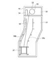
- FIG. 1 is a schematic configuration diagram illustrating an example of an elevator to which a soundness diagnosis device according to Embodiment 1 of the present invention is applied.
- FIG. 2 is a configuration diagram illustrating a state in which interlayer displacement due to an earthquake has occurred in the elevator of FIG. 1. It is a front view which shows the car door apparatus of the elevator of FIG. It is a front view which shows the landing door apparatus of the elevator of FIG.
- FIG. 5 is a plan view showing a positional relationship between the vane mechanism of FIG. 3 and a connecting roller of FIG. 4 when all doors are closed.
- FIG. 6 is a plan view showing a state where a landing door roller is sandwiched by the vane mechanism of FIG. 5.
- FIG. 7 is a plan view showing a state during a door opening operation of the vane mechanism and the landing door roller of FIG. 6.
- FIG. 6 is a plan view showing a state in which a displacement has occurred between the first car door and the second landing door of FIG. 5 due to an earthquake.
- FIG. 9 is a plan view illustrating a state where a landing door roller is sandwiched by the vane mechanism of FIG. 8.
- FIG. 10 is a plan view showing a state during a door opening operation of the vane mechanism and the landing door roller of FIG. 9.
- 4 is a graph illustrating an example of a rotation speed waveform and a torque waveform during a door opening operation of the door motor in FIG. 3.
- FIG. 4 is a block diagram illustrating the door control device of FIG.
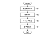
- FIG. 13 is a flowchart illustrating a determination criterion updating operation performed by the diagnostic apparatus main body of FIG. 13 is a flowchart illustrating a soundness diagnosis operation performed by the diagnostic device body of FIG. 12.
- FIG. 6 is a configuration diagram illustrating a health diagnostic device according to Embodiment 2 of the present invention.
- FIG. 9 is a configuration diagram illustrating a health diagnostic device according to Embodiment 3 of the present invention.
- FIG. 17 is a configuration diagram illustrating an example of a feature point to be detected by the feature point detector in FIG. 16.
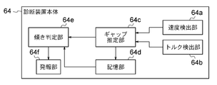
- FIG. 13 is a block diagram showing a soundness diagnosis apparatus according to Embodiment 4 of the present invention.
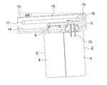
- FIG. 4 is a front view showing a state where the car door device of FIG. 3 is tilted due to the tilt of the car.
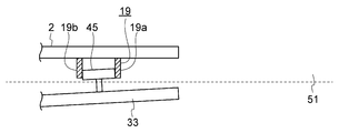
- FIG. 20 is a front view showing the relationship between the vane mechanism of FIG. 19 and a landing door roller when the car is located at a first position.
- FIG. 20 is a front view showing the relationship between the vane mechanism of FIG. 19 and a landing door roller when the car is located at a second position.
- FIG. 7 is a configuration diagram illustrating a first example of a processing circuit that implements each function of the diagnostic apparatus main body according to the first to fourth embodiments.
- FIG. 9 is a configuration diagram illustrating a second example of a processing circuit that implements each function of the diagnostic device main body according to the first to fourth embodiments.
- FIG. 1 is a schematic configuration diagram illustrating an example of an elevator to which a soundness diagnosis device according to Embodiment 1 of the present invention is applied.
- FIG. 2 is a configuration diagram showing a state in which interlayer displacement has occurred in the elevator of FIG. 1 due to an earthquake.
- a building 50 is provided with a hoistway 51 and a machine room 52.
- the machine room 52 is disposed right above the hoistway 51.
- a hoisting machine 53 and an elevator control device 54 are installed in the machine room 52.
- the hoist 53 has a drive sheave 55, a hoist motor (not shown), and a hoist brake (not shown).
- the hoist motor rotates the drive sheave 55.
- the hoisting machine brake keeps the drive sheave 55 stationary or brakes the rotation of the drive sheave 55.
- a suspension 56 is wound around the drive sheave 55.
- a plurality of ropes or a plurality of belts are used as the suspension 56.
- a car 57 is connected to the first end of the suspension 56.
- a counterweight (not shown) is connected to the second end of the suspension body 56.
- the car 57 and the counterweight are suspended in the hoistway 51 by a suspension body 56.
- the car 57 and the counterweight move up and down in the hoistway 51 by rotating the drive sheave 55.
- the elevator control device 54 controls the operation of the car 57 by controlling the hoisting machine 53.
- first car guide rail 58a and a second car guide rail 58b are installed in the hoistway 51.
- the first and second car guide rails 58a and 58b guide the car 57 up and down.
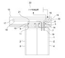
- FIG. 3 is a front view showing the car door device of the elevator of FIG. 1, and is a view of the car door device as seen from the landing side.
- the car entrance 1 is opened and closed by a first car door 2 and a second car door 3.
- the first car door 2 has a first car door panel 4 and a first car door hanger 5.
- the first car door hanger 5 is fixed to an upper part of the first car door panel 4.
- the first car door hanger 5 is provided with a pair of first car door rollers 6 and a pair of first car door up thrust rollers 7.
- the pair of first car door up thrust rollers 7 are disposed below the pair of first car door rollers 6.
- the second car door 3 has a second car door panel 8 and a second car door hanger 9.
- the second car door hanger 9 is fixed to an upper part of the second car door panel 8.
- the second car door hanger 9 is provided with a pair of second car door rollers 10 and a pair of second car door up thrust rollers 11.
- the pair of second car door up-thrust rollers 11 are arranged below the pair of second car door rollers 10.
- the car door girder 13 is fixed to the car above the car entrance 1.
- the car door girder 13 is provided with a car door rail 14.
- the first and second car doors 2 and 3 are suspended from a car door rail 14.
- the first and second car door rollers 6 and 10 move while rolling on the car door rail 14.
- the first and second car door up thrust rollers 7, 11 prevent the first and second car door rollers 6, 10 from dropping off the car door rail 14.
- a door motor 15 is fixed to the car door girder 13.
- the door motor 15 generates a driving force for causing the first and second car doors 2 and 3 to open and close. Further, the door motor 15 is disposed at one end of the car door beam 13 in the width direction of the car doorway 1. Further, the door motor 15 is disposed above the car door rail 14. The rotation axis of the door motor 15 is parallel and horizontal to the depth direction of the car.
- a motor pulley 16 is fixed to the rotation shaft of the door motor 15.
- An interlocking pulley 17 is provided at the other end of the car door girder 13 in the width direction of the car doorway 1.
- the interlocking pulley 17 is arranged above the car door rail 14.
- the rotation axis of the interlocking pulley 17 is parallel to the rotation axis of the door motor 15.
- An annular transmission 18 is wound between the motor pulley 16 and the interlocking pulley 17.
- the upper part and the lower part of the transmission body 18 are stretched in parallel to the width direction of the car doorway 1.
- the first car door 2 is provided with a vane mechanism 19.
- the transmission body 18 is provided with a gripping member 20.
- the gripping member 20 grips a lower portion of the transmission body 18.
- the movement of the transmission body 18 is transmitted to the first car door 2 via the holding member 20.
- the transmission body 18 is circulated by the door motor 15 and transmits the driving force of the door motor 15 to the first car door 2.
- the operation of opening and closing the first car door 2 is transmitted to the second car door 3 via the car door interlocking mechanism 21.
- the door motor 15 is controlled by a door control device 22.
- the car door device according to the first embodiment is of the single-door type. That is, the first and second car doors 2 and 3 move in the same direction during the opening / closing operation.
- the first car door 2 which is a high-speed door, is disposed farther from the door pocket when the car doorway 1 is fully closed.
- the second car door 3 which is a low-speed door, is disposed on the side close to the door pocket when the car doorway 1 is fully closed.
- the door pocket is on the left side of the second car door 3 in FIG.
- the first car door 2 moves faster than the second car door 3 during the opening and closing operation.
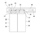
- FIG. 4 is a front view showing the landing door device of the elevator of FIG. 1, and is a view of the landing door device as seen from the hoistway side.
- the landing entrance 31 is opened and closed by a first landing door 32 and a second landing door 33.
- the first landing door 32 has a first landing door panel 34 and a first landing door hanger 35.
- the first landing door hanger 35 is fixed to an upper portion of the first landing door panel 34.
- the first landing door hanger 35 is provided with a pair of first landing door rollers 36 and a pair of first landing door up thrust rollers 37.
- the pair of first landing door up thrust rollers 37 are arranged below the pair of first landing door rollers 36.
- the second landing door 33 has a second landing door panel 38 and a second landing door hanger 39.
- the second landing door hanger 39 is fixed to an upper portion of the second landing door panel 38.
- the second landing door hanger 39 is provided with a pair of second landing door rollers 40 and a pair of second landing door up thrust rollers 41.
- the pair of second landing door up thrust rollers 41 are disposed below the pair of second landing door rollers 40.
- the landing door girder 43 is disposed above the landing entrance 31.
- the landing door girder 43 is provided with a landing door rail 44.
- the first and second landing doors 32 and 33 are suspended from a landing door rail 44.
- the first and second landing door rollers 36, 40 move while rolling on the landing door rails 44.
- the first and second landing door up thrust rollers 37, 41 prevent the first and second landing door rollers 36, 40 from falling off the landing door rail 44.
- the second landing door 33 is provided with a pair of connecting rollers 45 as connecting members.
- the connection roller 45 includes a fixed side interlock roller and a movable side interlock roller.
- the connecting roller 45 is sandwiched by the vane mechanism 19 when the car is landed and the first car door 2 is opened. As a result, the movable interlock roller rotates, and the locking device (not shown) is unlocked. Further, the vane mechanism 19 causes the second landing door 33 to interlock with the opening / closing operation of the first car door 2 by sandwiching the connecting roller 45.
- the landing door girder 43 is provided with a landing door interlocking mechanism 46.
- the opening / closing operation of the second landing door 33 is transmitted to the first landing door 32 via the landing door interlocking mechanism 46.
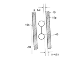
- FIG. 5 is a plan view showing the positional relationship between the vane mechanism 19 in FIG. 3 and the connecting roller 45 in FIG. 4 when all doors are closed.
- the vane mechanism 19 has a first vane 19a and a second vane 19b.
- the first vane 19a and the second vane 19b are arranged in parallel with each other and in the vertical direction. Further, the distance between the first vane 19a and the second vane 19b is variable.
- the gap dimension between the first vane 19a and the connecting roller 45 when all the doors are closed is X.
- FIG. 6 is a plan view showing a state where the connecting roller 45 is sandwiched by the vane mechanism 19 of FIG.
- FIG. 7 is a plan view showing a state during the door opening operation of the vane mechanism 19 and the connecting roller 45 in FIG.
- the second landing door 33 moves to the door pocket side integrally with the first car door 2.
- FIG. 8 is a plan view showing a state in which a displacement has occurred between the first car door 2 and the second landing door 33 of FIG. 5 due to the earthquake.
- interlayer displacement occurs in the building 50 due to the earthquake.
- the gap dimension changes to X + ⁇ X.
- the second landing door 33 has an angle shift of the angle shift amount ⁇ with respect to the first car door 2.
- FIG. 9 is a plan view showing a state where the connecting roller 45 is sandwiched by the vane mechanism 19 of FIG.
- FIG. 10 is a plan view showing a state during the door opening operation of the vane mechanism 19 and the connecting roller 45 in FIG.
- the second landing door 33 is performing an opening operation while being inclined with respect to the first car door 2.
- FIG. 11 is a graph showing an example of a rotation speed waveform and a torque waveform at the time of the door opening operation of the door motor 15 of FIG. As shown in FIG. 11, the gap size can be estimated from at least one of the rotation speed and the torque of the door motor 15.
- FIG. 12 is a block diagram showing the door control device 22 of FIG. 3 and the health diagnostic device of the first embodiment.
- the door motor 15 is provided with a rotation detector 23 that generates a signal according to the rotation speed of the door motor 15.
- a rotation detector 23 for example, a resolver or an encoder is used.
- the door control device 22 has, as functional blocks, a speed command unit 22a, a speed control unit 22b, a current control unit 22c, a speed calculation unit 22d, and a filter processing unit 22e.
- the speed command unit 22a generates a rotation speed command value of the door motor 15 for causing the first and second car doors 2 and 3 to open and close, and outputs the rotation speed command value to the speed control unit 22b.
- the speed control unit 22b corrects an error between the actual rotation speed of the door motor 15 and the rotation speed command value.
- the speed control unit 22b receives the rotation speed command value output from the speed command unit 22a and the actual rotation speed of the door motor 15 obtained from the speed calculation unit 22d and the filter processing unit 22e.
- an error is obtained by inputting the rotation speed command value and the actual rotation speed of the door motor 15 to the first adder / subtractor 24. Then, the speed control unit 22b outputs the rotation speed command value with the error corrected to the current control unit 22c as a current command value.
- the current control unit 22c controls the current supplied to the door motor 15 based on the current command value.
- the output of the current control unit 22c is input to the door motor 15 via a pulse width modulation inverter (not shown).
- the current control unit 22c corrects the current command value from the speed control unit 22b based on the current value detected by the current detector 25.
- an error is obtained by inputting the current command value from the speed control unit 22b and the current value detected by the current detector 25 to the second adder / subtractor 26.
- the motor rotation position or the rotation speed can be estimated using the current value detected by the current detector 25 instead of the rotation detector 23.
- the speed calculator 22d calculates the rotation speed by sampling the input rotation position at regular intervals, and outputs the rotation speed to the filter processor 22e.
- the filter processing unit 22e performs low-pass filter processing on the input rotation speed.
- the low-pass filter process is a process of excluding a vibration component in a high frequency region and extracting a low frequency region necessary for speed control.
- the door control device 22 has a computer.
- the function of the door control device 22 can be realized by arithmetic processing by a computer.
- the soundness diagnostic device of the first embodiment has a diagnostic device main body 61.
- the diagnostic device main body 61 diagnoses the soundness of the diagnostic target after the occurrence of the earthquake.
- the diagnosis target is at least one of the building 50 and the elevator.
- the diagnostic device main body 61 determines, as the soundness of the diagnosis target after the occurrence of the earthquake, whether or not there is an abnormality that hinders the automatic restart of the elevator.
- the diagnostic device main body 61 includes, as functional blocks, a speed detecting unit 61a, a torque detecting unit 61b, a gap estimating unit 61c, a storage unit 61d, a gap determining unit 61e as a diagnostic unit, a torque determining unit 61f as a diagnostic unit, and It has a reporting unit 61g.
- the speed detector 61a detects the rotation speed of the door motor 15 based on the output from the rotation detector 23.
- the torque detector 61b detects the torque of the door motor 15 based on the current command value output from the speed controller 22b.
- the gap estimating unit 61c estimates a gap size between the first vane 19a and the connection roller 45 when the door is completely closed, based on the rotation speed and the torque of the door motor 15.
- the diagnostic device main body 61 outputs an estimation operation command to the door control device 22.
- the door control device 22 Upon receiving the estimation operation command, the door control device 22 causes the first and second car doors 2 and 3 to open at a lower speed than usual with the car 57 landing on the landing floor. At this time, the gap estimating unit 61c estimates the gap size from changes in the rotation speed and torque of the door motor 15.
- the storage unit 61d stores a gap reference value corresponding to the gap size before the occurrence of the earthquake.
- the gap reference value is, for example, a gap size before the occurrence of an earthquake, or a value obtained by adding an allowable value to the gap size before the occurrence of an earthquake.
- the storage unit 61d stores a torque reference waveform corresponding to the torque waveform before the occurrence of the earthquake.
- the torque reference waveform is, for example, a torque waveform at the time of the door opening operation of the door motor 15 before the occurrence of the earthquake.
- the diagnostic device main body 61 periodically updates the gap reference value and the torque reference waveform.
- the update cycle is, for example, once a day, once a week, or once a month.
- the update may be performed when the elevator is started.
- the update may be performed when an update command is manually input.
- the gap determining unit 61e determines whether there is an abnormality in the diagnosis target after the earthquake by comparing the post-earthquake estimated value, which is the estimated value of the gap size after the earthquake, with the gap reference value. Thereby, the gap determination unit 61e diagnoses the soundness of the diagnosis target after the occurrence of the earthquake.
- the gap determination unit 61e determines that there is an abnormality when the difference between the post-earthquake estimated value and the gap reference value exceeds an allowable value.
- the gap determination unit 61e determines that there is an abnormality when the post-earthquake estimated value exceeds the gap reference value.
- the torque determination unit 61f determines whether there is an abnormality in the diagnosis target after the earthquake by comparing the post-earthquake waveform, which is the torque waveform after the earthquake, with the torque reference waveform. Thereby, the torque determination unit 61f diagnoses the soundness of the diagnosis target after the occurrence of the earthquake.
- the reporting unit 61g reports the determination results by the gap determining unit 61e and the torque determining unit 61f to the elevator control device 54 and a remote control room.
- FIG. 13 is a flowchart showing the determination reference updating operation by the diagnostic device main body 61 of FIG.
- the diagnostic device main body 61 updates the gap reference value and the torque reference waveform at the above timing.
- the diagnostic device main body 61 outputs an estimation operation command to the door control device 22 in step S1.
- the diagnostic device main body 61 acquires information on the rotation speed and the torque of the door motor 15 in step S2. Then, in step S3, the diagnostic device main body 61 estimates the gap size based on the acquired information. Thereafter, in step S4, the diagnostic device main body 61 updates the gap reference value and the torque reference waveform, and ends the processing.
- FIG. 14 is a flowchart showing a soundness diagnosis operation by the diagnosis device main body 61 of FIG.
- the diagnostic device main body 61 periodically executes the process of FIG. 14 at a set cycle.
- step S11 the diagnostic device main body 61 confirms whether or not an earthquake of a set seismic intensity or higher has been detected.
- the diagnostic device main body 61 ends the current process. If an earthquake has been detected, the diagnostic device main body 61 checks in step S12 whether the shaking of the earthquake has subsided. If the shaking has not stopped, the diagnostic device main body 61 ends the current process.
- the diagnostic device main body 61 checks in step S13 whether the set time has elapsed. If the set time has not elapsed, the diagnostic device main body 61 ends the current process.
- the diagnostic device main body 61 If the set time has elapsed, the diagnostic device main body 61 outputs an estimated operation command to the door control device 22 in step S14. Subsequently, the diagnostic device main body 61 acquires information on the rotation speed and the torque of the door motor 15 in step S15. Then, in step S16, the diagnostic device main body 61 estimates the gap size after the occurrence of the earthquake based on the acquired information.
- step S17 the diagnostic device main body 61 determines whether there is any abnormality in the diagnosis target. Subsequently, in step S18, the diagnostic device main body 61 outputs the determination result to the elevator control device 54 and the remote control room, and ends the processing.
- the diagnostic device main body 61 estimates the gap size from the rotation speed and the torque of the door motor 15. Then, the diagnostic device main body 61 diagnoses the soundness of the diagnosis target after the occurrence of the earthquake by comparing the gap size after the occurrence of the earthquake with the gap reference value. Therefore, the configuration can be simplified and the cost can be reduced.
- the diagnostic device main body 61 diagnoses the soundness of the diagnosis target after the occurrence of the earthquake by comparing the torque waveform of the door motor 15 with the torque reference waveform. Therefore, the configuration can be simplified and the cost can be reduced.
- the diagnostic apparatus main body 61 can estimate the degree of the interlayer displacement due to the earthquake from the gap size and the torque fluctuation, and can diagnose the soundness of the diagnosis target.
- the diagnostic device main body 61 periodically updates the gap reference value and the torque reference waveform. For this reason, the secular change can be removed and the damage caused by the earthquake can be estimated more accurately.
- the gap reference value and the torque reference waveform are set for each landing floor.
- the soundness diagnosis operation is preferably performed on all landing floors, a part of the landing floors may be selected and executed.
- the threshold value of the gap dimension may be manually set as the gap reference value.
- the torque reference waveform may be manually set.
- the gap size may be estimated from only the rotation speed or the torque of the door motor 15.
- the single-door type door device is described, but the door device may be a centrally-open type. Further, the number of doors is not limited to two.
- the connecting member is not limited to the connecting roller 45.
- FIG. 15 is a configuration diagram showing a health diagnostic apparatus according to Embodiment 2 of the present invention.
- the soundness diagnostic device of the second embodiment has a gap detector 71 and a diagnostic device main body 62.
- the gap detector 71 is provided in the car 57.
- the gap detector 71 is installed on the ceiling of the cab.
- the gap detector 71 detects a gap dimension between the car sill 72 and the landing sill 73.
- a camera is used as the gap detector 71.
- the car sill 72 is installed on the floor of the car entrance 1.
- the landing sill 73 is installed on the floor of the landing entrance 31.
- the diagnostic device main body 62 diagnoses the soundness of the diagnosis target after the occurrence of the earthquake by comparing the gap size after the occurrence of the earthquake with the gap reference value. Further, the diagnostic device main body 62 has a gap detection unit 62a, a storage unit 62b, a gap determination unit 62c, and a notification unit 62d as functional blocks.
- the gap detection unit 62a obtains a gap dimension between the car threshold 72 and the landing threshold 73 based on a signal from the gap detector 71.
- the storage unit 62b stores a gap reference value that is a value corresponding to the gap dimension before the occurrence of the earthquake.
- the gap reference value is, for example, a gap dimension before the occurrence of an earthquake or a value obtained by adding an allowable value to a gap dimension before an earthquake.
- the diagnostic device main body 62 periodically updates the gap reference value, similarly to the gap reference value of the first embodiment.
- the gap determining unit 62c compares the post-earthquake dimension, which is the gap dimension after the occurrence of the earthquake, with the gap reference value to determine whether there is an abnormality in the diagnosis target after the occurrence of the earthquake.
- the gap determination unit 62c determines that there is an abnormality when the difference between the post-earthquake dimension and the gap reference value exceeds an allowable value.
- the gap determination unit 62c determines that there is an abnormality when the size after the earthquake exceeds the gap reference value.
- the reporting unit 62d reports the determination result by the gap determining unit 62c to the elevator control device 54 and a remote control room.
- Other configurations and operations are the same as those of the first embodiment.
- the diagnostic device body 62 diagnoses the soundness of the diagnosis target after the occurrence of the earthquake by comparing the gap size after the occurrence of the earthquake with the gap reference value.
- the gap detector 71 is provided on the car 57. Therefore, the configuration can be simplified and the cost can be reduced.
- the degree of interlayer displacement due to the earthquake can be estimated from the gap size, and the soundness of the diagnosis target can be diagnosed.
- the hall camera 74 In the case where the hall camera 74 is provided on the ceiling of the hall, the hall camera 74 can be used as a gap detector. However, in that case, it becomes necessary to install the hall camera 74 in each hall.
- the diagnostic device main body 62 periodically updates the gap reference value. For this reason, the secular change can be removed and the damage caused by the earthquake can be estimated more accurately.
- the gap detector 71 is not limited to a camera.
- the gap reference value for each landing floor.
- the soundness diagnosis operation is preferably performed on all landing floors, a part of the landing floors may be selected and executed.
- the threshold value of the gap size may be manually set as the gap reference value.
- FIG. 16 is a configuration diagram showing a health diagnostic apparatus according to Embodiment 3 of the present invention.
- the soundness diagnostic device according to the third embodiment includes a feature point detector 75 and a diagnostic device main body 63.
- the feature point detector 75 is provided on the first car door 2.
- the feature point detector 75 detects the position of a feature point that is a part of the landing door device.
- a camera is used as the feature point detector 75.
- the diagnostic device body 63 diagnoses the soundness of the diagnostic object after the earthquake by comparing the position of the feature point after the earthquake with the reference position.
- the diagnostic device main body 63 has, as functional blocks, a position detection unit 63a, a storage unit 63b, a position determination unit 63c, and a notification unit 63d.
- the position detection unit 63a obtains the position of the feature point based on the signal from the feature point detector 75.
- the storage unit 63b stores a reference position that is a position of a feature point before the occurrence of an earthquake.
- the position determination unit 63c determines whether there is an abnormality in the diagnosis target after the earthquake by comparing the post-earthquake position, which is the position of the feature point after the earthquake, with the reference position. The position determining unit 63c determines that there is an abnormality when the amount of displacement of the post-earthquake position with respect to the reference position exceeds a threshold.
- the reporting unit 63d reports the determination result by the position determining unit 63c to the elevator control device 54 and a remote control room.
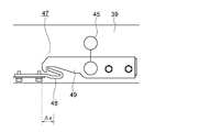
- FIG. 17 is a configuration diagram showing an example of a feature point to be detected by the feature point detector 75 in FIG. Although omitted in FIG. 4, the landing door device is provided with an interlock device 47.
- the interlock device 47 prevents the first and second landing doors 32 and 33 from being opened by an operation from the landing when the car 57 is not on the floor.
- the interlock device 47 has a latch receiving member 48 and a latch 49.
- the latch receiving member 48 is fixed to the landing door girder 43.
- the latch 49 is rotatably provided on the second landing door hanger 39. When the latch 49 is hooked on the latch receiving member 48, the opening operation of the first and second landing doors 32, 33 is prevented.
- the tip of the latch 49 can be used as a feature point.
- FIG. 17 shows that the tip of the latch 49, which is a feature point, is shifted by ⁇ x before and after the earthquake.
- Other configurations and operations are the same as those of the first embodiment.
- the diagnostic device main body 63 of the third embodiment diagnoses the soundness of the diagnostic target after the occurrence of the earthquake by comparing the positions of the characteristic points after the occurrence of the earthquake with the reference positions.
- the feature point detector 75 is provided in the car 57. Therefore, the configuration can be simplified and the cost can be reduced.
- the degree of interlayer displacement due to the earthquake can be estimated from the displacement of feature points, and the soundness of the diagnosis target can be diagnosed.
- the diagnostic device main body 63 periodically updates the reference position. For this reason, the secular change can be removed and the damage caused by the earthquake can be estimated more accurately.
- the feature point detector 75 is not limited to a camera.
- the reference position is set for each landing floor.
- the soundness diagnosis operation is preferably performed on all landing floors, a part of the landing floors may be selected and executed.
- FIG. 18 is a block diagram showing a health diagnostic apparatus according to Embodiment 4 of the present invention.
- the health diagnostic device of the fourth embodiment has a diagnostic device main body 64.
- the diagnostic device main body 64 has, as functional blocks, a speed detecting unit 64a, a torque detecting unit 64b, a gap estimating unit 64c, a storage unit 64d, an inclination determining unit 64e as a diagnostic unit, and an alarm unit 64f.
- the functions of the speed detector 64a, the torque detector 64b, and the gap estimator 64c are the same as the functions of the speed detector 61a, the torque detector 61b, and the gap estimator 61c of the first embodiment, respectively.
- the diagnostic device main body 64 obtains the gap size when the car 57 is stopped at the first position by the same estimation method as in the first embodiment. Further, the diagnostic apparatus main body 64 obtains the gap size when the car 57 is stopped at the second position vertically displaced from the first position by the same estimation method as in the first embodiment.
- the diagnostic device main body 64 also determines the difference between the gap size at the first position and the gap size at the second position.
- the first position and the second position are positions where the connecting roller 45 is disposed inside the vane mechanism 19 on the same landing floor.
- the storage unit 64d stores the estimated gap size. In addition, the storage unit 64d stores an allowable angle of inclination of the car 57.
- the inclination determining unit 64e diagnoses the soundness of the diagnosis target after the occurrence of the earthquake based on the difference.
- the inclination determining unit 64e estimates the inclination angle of the car 57 based on the difference between the gap dimensions. Further, the inclination determining unit 64e diagnoses the soundness of the diagnosis target after the occurrence of the earthquake by comparing the estimated inclination angle with the allowable angle.
- the reporting unit 64f reports the determination result by the tilt determining unit 64e to the elevator control device 54 and a remote control room.
- FIG. 19 is a front view showing a state in which the car door device of FIG. In the example of FIG. 19, the car door device is inclined from the horizontal state by an angle ⁇ in a direction in which the second car door 3 side is lowered.
- FIG. 20 is a front view showing the relationship between the vane mechanism 19 and the connection roller 45 in FIG. 19 when the car 57 is located at the first position. Since the car door device is tilted by ⁇ , the first and second vanes 19a and 19b are also tilted by ⁇ with respect to the vertical direction.
- the gap dimension between the lower connecting roller 45 and the first vane 19a increases by ⁇ X.
- the gap dimension between the upper connecting roller 45 and the first vane 19a is reduced by ⁇ X.
- FIG. 21 is a front view showing the relationship between the vane mechanism 19 and the connecting roller 45 in FIG. 19 when the car 57 is located at the second position. At the second position, the gap dimension between the lower connecting roller 45 and the first vane 19a is further increased by ⁇ y with respect to the first position.
- the inclination determining unit 64e can estimate the inclination angle of the car 57 with respect to the landing door device based on the distance between the first position and the second position and ⁇ y. Then, when the tilt angle exceeds the allowable angle, the tilt determination unit 64e determines that there is an abnormality.
- Other configurations and operations are the same as those of the first embodiment.
- the diagnostic apparatus main body 64 of the fourth embodiment has a difference between the gap size when the car 57 is stopped at the first position and the gap size when the car 57 is stopped at the second position. Is determined, and the soundness of the diagnosis target is diagnosed based on the difference. Therefore, the configuration can be simplified and the cost can be reduced.
- the degree of interlayer displacement due to the earthquake can be estimated from the inclination angle of the car 57, and the soundness of the diagnosis target can be diagnosed.
- the soundness diagnosis operation of the fourth embodiment may be performed at times other than after the occurrence of an earthquake.
- the soundness diagnosis operation of the fourth embodiment is performed for each landing floor.
- the soundness diagnosis operation of the fourth embodiment is preferably executed at all landing floors, but may be executed by selecting some landing floors.
- FIG. 22 is a configuration diagram illustrating a first example of a processing circuit that realizes each function of the diagnostic device main bodies 61 to 64 according to the first to fourth embodiments.
- the processing circuit 100 of the first example is dedicated hardware.
- the processing circuit 100 is, for example, a single circuit, a composite circuit, a programmed processor, a parallel programmed processor, an ASIC (Application Specific Integrated Circuit), an FPGA (Field Programmable Gate Array), or a combination thereof. Applicable. Further, each function of the diagnostic device main bodies 61 to 64 may be realized by the individual processing circuit 100, or each function may be realized by the processing circuit 100 collectively.
- FIG. 23 is a configuration diagram showing a second example of a processing circuit that realizes each function of the diagnostic device main bodies 61 to 64 of the first to fourth embodiments.
- the processing circuit 200 of the second example includes a processor 201 and a memory 202.
- each function of the diagnostic device main bodies 61 to 64 is realized by software, firmware, or a combination of software and firmware.
- Software and firmware are described as programs and stored in the memory 202.
- the processor 201 implements each function by reading and executing the program stored in the memory 202.
- the program stored in the memory 202 causes a computer to execute the procedure or method of each unit described above.
- the memory 202 is, for example, a RAM (Random Access Memory), a ROM (Read Only Memory), a flash memory, an EPROM (Erasable Programmable Read Memory Only), an EEPROM (Electrical Memory, etc.). Or volatile semiconductor memory.
- a magnetic disk, a flexible disk, an optical disk, a compact disk, a mini disk, a DVD, and the like also correspond to the memory 202.
- the processing circuit can realize the function of each unit described above by hardware, software, firmware, or a combination thereof.
- 2 1st car door, 15 door motor, 19 vane mechanism, 33 second landing door, 45 linkage roller (connection member), 61c, 64c gap estimation unit, 61d, 64d storage unit, 61e gap determination unit (diagnosis unit) 61f ⁇ torque determination section (diagnosis section), 62, 63 ⁇ diagnosis apparatus main body, 64e ⁇ tilt determination section (diagnosis section), 71 ⁇ gap detector, 72 ⁇ car threshold, 73 # landing threshold, 75 # feature point detector.
Landscapes
- Maintenance And Inspection Apparatuses For Elevators (AREA)
- Elevator Door Apparatuses (AREA)
Abstract
健全性診断装置は、ギャップ推定部、記憶部、及び診断部を有している。ギャップ推定部は、乗場ドアに設けられている連結部材と、かごドアに設けられているベーン機構との間のギャップ寸法を、ドアモータの回転速度及びトルクの少なくともいずれか一方から推定する。記憶部は、ギャップ基準値を記憶する。診断部は、地震発生後のギャップ寸法をギャップ基準値と比較することにより、建物とエレベータとの少なくともいずれか一方である診断対象の地震発生後の健全性を診断する。
Description
この発明は、エレベータが設けられている建物とエレベータとの少なくともいずれか一方である診断対象の健全性を診断する健全性診断装置に関するものである。
従来のエレベータ仮復旧運転システムでは、乗場三方枠に距離センサとターゲットとが設けられている。距離センサは、乗場出入口の幅方向の一端部の上部に配置されている。ターゲットは、乗場出入口の幅方向の他端部の下部に配置されている。評価部は、乗場三方枠の変形量から、地震前後の建物の層間変位量を求める(例えば、特許文献1参照)。
上記のような従来のエレベータ仮復旧運転システムでは、各階の乗場三方枠に距離センサ及びターゲットを設置する必要があり、構成が複雑になるとともに、コストが高くなる。
この発明は、上記のような課題を解決するためになされたものであり、構成を簡単にしてコストの低減を図ることができる健全性診断装置を得ることを目的とする。
この発明に係る健全性診断装置は、エレベータの乗場ドアに設けられている連結部材と、エレベータのかごドアに設けられており、連結部材を挟み込むことにより、乗場ドアをかごドアに連動させるベーン機構との間のギャップ寸法を、エレベータのドアモータの回転速度及びトルクの少なくともいずれか一方から推定するギャップ推定部、ギャップ基準値を記憶する記憶部、及び地震発生後のギャップ寸法をギャップ基準値と比較することにより、エレベータが設けられている建物とエレベータとの少なくともいずれか一方である診断対象の地震発生後の健全性を診断する診断部を備えている。
また、この発明に係る健全性診断装置は、地震発生前のエレベータのドアモータのトルク波形に対応するトルク基準波形を記憶する記憶部、及び地震発生後のドアモータのトルク波形をトルク基準波形と比較することにより、エレベータが設けられている建物とエレベータとの少なくともいずれか一方である診断対象の地震発生後の健全性を診断する診断部を備えている。
また、この発明に係る健全性診断装置は、エレベータのかごに設けられており、かご敷居と乗場敷居との間の隙間寸法を検出する隙間検出器、及び地震発生後の隙間寸法を隙間基準値と比較することにより、エレベータが設けられている建物とエレベータとの少なくともいずれか一方である診断対象の地震発生後の健全性を診断する診断装置本体を備えている。
また、この発明に係る健全性診断装置は、エレベータのかごに設けられており、乗場ドア装置の一部である特徴点の位置を検出する特徴点検出器、及び地震発生後の特徴点の位置を基準位置と比較することにより、エレベータが設けられている建物とエレベータとの少なくともいずれか一方である診断対象の地震発生後の健全性を診断する診断装置本体を備えている。
また、この発明に係る健全性診断装置は、エレベータの乗場ドアに設けられている連結部材と、エレベータのかごドアに設けられており、連結部材を挟み込むことにより、乗場ドアをかごドアに連動させるベーン機構との間のギャップ寸法を、エレベータのドアモータの回転速度及びトルクの少なくともいずれか一方から推定するギャップ推定部、エレベータのかごの傾きの許容角度を記憶する記憶部、及びかごを第1の位置で停止させたときのギャップ寸法と、第1の位置に対して上下方向にずらされた第2の位置でかごを停止させたときのギャップ寸法との差分を求め、差分に基づいて、かごの傾き角度を推定し、推定した傾き角度と許容角度とを比較することにより、エレベータが設けられている建物とエレベータとの少なくともいずれか一方である診断対象の健全性を診断する診断部を備えている。
また、この発明に係る健全性診断装置は、地震発生前のエレベータのドアモータのトルク波形に対応するトルク基準波形を記憶する記憶部、及び地震発生後のドアモータのトルク波形をトルク基準波形と比較することにより、エレベータが設けられている建物とエレベータとの少なくともいずれか一方である診断対象の地震発生後の健全性を診断する診断部を備えている。
また、この発明に係る健全性診断装置は、エレベータのかごに設けられており、かご敷居と乗場敷居との間の隙間寸法を検出する隙間検出器、及び地震発生後の隙間寸法を隙間基準値と比較することにより、エレベータが設けられている建物とエレベータとの少なくともいずれか一方である診断対象の地震発生後の健全性を診断する診断装置本体を備えている。
また、この発明に係る健全性診断装置は、エレベータのかごに設けられており、乗場ドア装置の一部である特徴点の位置を検出する特徴点検出器、及び地震発生後の特徴点の位置を基準位置と比較することにより、エレベータが設けられている建物とエレベータとの少なくともいずれか一方である診断対象の地震発生後の健全性を診断する診断装置本体を備えている。
また、この発明に係る健全性診断装置は、エレベータの乗場ドアに設けられている連結部材と、エレベータのかごドアに設けられており、連結部材を挟み込むことにより、乗場ドアをかごドアに連動させるベーン機構との間のギャップ寸法を、エレベータのドアモータの回転速度及びトルクの少なくともいずれか一方から推定するギャップ推定部、エレベータのかごの傾きの許容角度を記憶する記憶部、及びかごを第1の位置で停止させたときのギャップ寸法と、第1の位置に対して上下方向にずらされた第2の位置でかごを停止させたときのギャップ寸法との差分を求め、差分に基づいて、かごの傾き角度を推定し、推定した傾き角度と許容角度とを比較することにより、エレベータが設けられている建物とエレベータとの少なくともいずれか一方である診断対象の健全性を診断する診断部を備えている。
この発明の健全性診断装置によれば、構成を簡単にしてコストの低減を図ることができる。
以下、この発明を実施するための形態について、図面を参照して説明する。
実施の形態1.
図1は、この発明の実施の形態1による健全性診断装置が適用されるエレベータの一例を示す概略の構成図である。また、図2は、図1のエレベータに地震よる層間変位が発生した状態を示す構成図である。
実施の形態1.
図1は、この発明の実施の形態1による健全性診断装置が適用されるエレベータの一例を示す概略の構成図である。また、図2は、図1のエレベータに地震よる層間変位が発生した状態を示す構成図である。
図において、建物50には、昇降路51及び機械室52が設けられている。機械室52は、昇降路51の真上に配置されている。機械室52には、巻上機53及びエレベータ制御装置54が設置されている。
巻上機53は、駆動シーブ55、図示しない巻上機モータ、及び図示しない巻上機ブレーキを有している。巻上機モータは、駆動シーブ55を回転させる。巻上機ブレーキは、駆動シーブ55の静止状態を保持、又は駆動シーブ55の回転を制動する。
駆動シーブ55には、懸架体56が巻き掛けられている。懸架体56としては、複数本のロープ又は複数本のベルトが用いられている。
懸架体56の第1の端部には、かご57が接続されている。懸架体56の第2の端部には、図示しない釣合おもりが接続されている。かご57及び釣合おもりは、懸架体56により昇降路51内に吊り下げられている。また、かご57及び釣合おもりは、駆動シーブ55を回転させることにより、昇降路51内を昇降する。
エレベータ制御装置54は、巻上機53を制御することにより、かご57の運行を制御する。
昇降路51内には、第1のかごガイドレール58aと第2のかごガイドレール58bとが設置されている。第1及び第2のかごガイドレール58a,58bは、かご57の昇降を案内する。
図3は、図1のエレベータのかごドア装置を示す正面図であり、かごドア装置を乗場側から見た図である。
かご出入口1は、第1のかごドア2及び第2のかごドア3により開閉される。第1のかごドア2は、第1のかごドアパネル4と、第1のかごドアハンガ5とを有している。第1のかごドアハンガ5は、第1のかごドアパネル4の上部に固定されている。
第1のかごドアハンガ5には、一対の第1のかごドアローラ6と、一対の第1のかごドアアップスラストローラ7とが設けられている。一対の第1のかごドアアップスラストローラ7は、一対の第1のかごドアローラ6の下方に配置されている。
第2のかごドア3は、第2のかごドアパネル8と、第2のかごドアハンガ9とを有している。第2のかごドアハンガ9は、第2のかごドアパネル8の上部に固定されている。
第2のかごドアハンガ9には、一対の第2のかごドアローラ10と、一対の第2のかごドアアップスラストローラ11とが設けられている。一対の第2のかごドアアップスラストローラ11は、一対の第2のかごドアローラ10の下方に配置されている。
かごドア桁13は、かご出入口1の上方で、かごに固定されている。かごドア桁13には、かごドアレール14が設けられている。第1及び第2のかごドア2,3は、かごドアレール14から吊り下げられている。
第1及び第2のかごドア2,3の開閉動作時には、第1及び第2のかごドアローラ6,10は、かごドアレール14上を転がりながら移動する。第1及び第2のかごドアアップスラストローラ7,11は、第1及び第2のかごドアローラ6,10のかごドアレール14からの脱落を防止する。
かごドア桁13には、ドアモータ15が固定されている。ドアモータ15は、第1及び第2のかごドア2,3に開閉動作をさせる駆動力を発生する。また、ドアモータ15は、かご出入口1の幅方向のかごドア桁13の一端部に配置されている。また、ドアモータ15は、かごドアレール14の上方に配置されている。ドアモータ15の回転軸は、かごの奥行き方向に平行、かつ水平である。
ドアモータ15の回転軸には、モータプーリ16が固定されている。かご出入口1の幅方向のかごドア桁13の他端部には、連動プーリ17が設けられている。連動プーリ17は、かごドアレール14の上方に配置されている。連動プーリ17の回転軸は、ドアモータ15の回転軸に平行である。
モータプーリ16と連動プーリ17との間には、環状の伝達体18が巻かれている。伝達体18としては、例えば伝達ベルトが用いられている。伝達体18の上側部分及び下側部分は、かご出入口1の幅方向に平行に張られている。
第1のかごドア2には、ベーン機構19が設けられている。伝達体18には、把持部材20が設けられている。把持部材20は、伝達体18の下側部分を把持している。伝達体18の動きは、把持部材20を介して第1のかごドア2に伝達される。伝達体18は、ドアモータ15により循環動作し、ドアモータ15の駆動力を第1のかごドア2に伝達する。
第1のかごドア2の開閉動作は、かごドア連動機構21を介して第2のかごドア3に伝達される。ドアモータ15は、ドア制御装置22によって制御されている。
実施の形態1のかごドア装置は、片開き式である。即ち、第1及び第2のかごドア2,3は、開閉動作時に同方向へ移動する。
高速ドアである第1のかごドア2は、かご出入口1の全閉時に、戸袋から遠い側に配置されている。低速ドアである第2のかごドア3は、かご出入口1の全閉時に、戸袋に近い側に配置されている。戸袋は、図3の第2のかごドア3の左側である。第1のかごドア2は、開閉動作時に、第2のかごドア3よりも高速で移動する。
図4は、図1のエレベータの乗場ドア装置を示す正面図であり、乗場ドア装置を昇降路側から見た図である。
乗場出入口31は、第1の乗場ドア32及び第2の乗場ドア33により開閉される。第1の乗場ドア32は、第1の乗場ドアパネル34と、第1の乗場ドアハンガ35とを有している。第1の乗場ドアハンガ35は、第1の乗場ドアパネル34の上部に固定されている。
第1の乗場ドアハンガ35には、一対の第1の乗場ドアローラ36と、一対の第1の乗場ドアアップスラストローラ37とが設けられている。一対の第1の乗場ドアアップスラストローラ37は、一対の第1の乗場ドアローラ36の下方に配置されている。
第2の乗場ドア33は、第2の乗場ドアパネル38と、第2の乗場ドアハンガ39とを有している。第2の乗場ドアハンガ39は、第2の乗場ドアパネル38の上部に固定されている。
第2の乗場ドアハンガ39には、一対の第2の乗場ドアローラ40と、一対の第2の乗場ドアアップスラストローラ41とが設けられている。一対の第2の乗場ドアアップスラストローラ41は、一対の第2の乗場ドアローラ40の下方に配置されている。
乗場ドア桁43は、乗場出入口31の上方に配置されている。乗場ドア桁43には、乗場ドアレール44が設けられている。第1及び第2の乗場ドア32,33は、乗場ドアレール44から吊り下げられている。
第1及び第2の乗場ドア32,33の開閉動作時には、第1及び第2の乗場ドアローラ36,40は、乗場ドアレール44上を転がりながら移動する。第1及び第2の乗場ドアアップスラストローラ37,41は、第1及び第2の乗場ドアローラ36,40の乗場ドアレール44からの脱落を防止する。
第2の乗場ドア33には、連結部材としての一対の連結ローラ45が設けられている。連結ローラ45には、固定側インターロックローラと可動側インターロックローラとが含まれている。
連結ローラ45は、かごが着床し第1のかごドア2が開放動作する際、ベーン機構19により挟み込まれる。これにより、可動側インターロックローラが回転し、図示しない錠装置が解錠される。また、ベーン機構19は、連結ローラ45を挟み込むことにより、第2の乗場ドア33を第1のかごドア2の開閉動作に連動させる。
乗場ドア桁43には、乗場ドア連動機構46が設けられている。第2の乗場ドア33の開閉動作は、乗場ドア連動機構46を介して第1の乗場ドア32に伝達される。
図5は、全戸閉時における図3のベーン機構19と図4の連結ローラ45との位置関係を示す平面図である。ベーン機構19は、第1のベーン19aと第2のベーン19bとを有している。第1のベーン19a及び第2のベーン19bは、互いに平行、かつ鉛直方向に平行に配置されている。また、第1のベーン19aと第2のベーン19bとの間隔は、可変である。
全戸閉時には、第1のベーン19a及び第2のベーン19bは、それぞれ連結ローラ45から離れている。全戸閉時の第1のベーン19aと連結ローラ45との間のギャップ寸法は、Xである。
図6は、図5のベーン機構19により連結ローラ45が挟み込まれた状態を示す平面図である。また、図7は、図6のベーン機構19及び連結ローラ45の戸開動作中の状態を示す平面図である。
ドアモータ15が戸開動作を開始すると、まず第1のベーン19aと第2のベーン19bとの間隔が狭められ、第1のベーン19aと第2のベーン19bとの間に連結ローラ45が挟み込まれる。
この後、第1のかごドア2が戸袋側へ移動を開始すると、第2の乗場ドア33が第1のかごドア2と一体に戸袋側へ移動する。
図8は、図5の第1のかごドア2と第2の乗場ドア33との間に地震による位置ずれが生じた状態を示す平面図である。図8の例では、地震により建物50に層間変位が発生している。これにより、ギャップ寸法がX+ΔXに変化している。また、第1のかごドア2に対して、角度ずれ量Δθの角度ずれが第2の乗場ドア33に生じている。
図9は、図8のベーン機構19により連結ローラ45が挟み込まれた状態を示す平面図である。また、図10は、図9のベーン機構19及び連結ローラ45の戸開動作中の状態を示す平面図である。
図10の状態では、第2の乗場ドア33は、第1のかごドア2に対して傾斜した状態のまま開放動作している。
図11は、図3のドアモータ15の戸開動作時の回転速度波形及びトルク波形の一例を示すグラフである。図11に示すように、ギャップ寸法は、ドアモータ15の回転速度及びトルクの少なくともいずれか一方から推定することができる。
また、地震により、図8~10に示すように、第1のかごドア2に対する第2の乗場ドア33の角度ずれが生じた場合、第2の乗場ドア33に走行ロスが生じる。このため、角度ずれ量は、図11に示すようなトルク波形の増大から推定することができる。また、地震による乗場ドアレール44の変形も、トルク変動から推定することができる。
図12は、図3のドア制御装置22と実施の形態1の健全性診断装置とを示すブロック図である。ドアモータ15には、ドアモータ15の回転速度に応じた信号を発生する回転検出器23が設けられている。回転検出器23としては、例えばレゾルバ、又はエンコーダが用いられている。
ドア制御装置22は、機能ブロックとして、速度指令部22a、速度制御部22b、電流制御部22c、速度演算部22d、及びフィルタ処理部22eを有している。
速度指令部22aは、第1及び第2のかごドア2,3に開閉動作をさせるためのドアモータ15の回転速度指令値を生成して速度制御部22bに出力する。
速度制御部22bは、ドアモータ15の実回転速度と回転速度指令値との誤差を補正する。また、速度制御部22bには、速度指令部22aの出力である回転速度指令値と、速度演算部22d及びフィルタ処理部22eから得られるドアモータ15の実回転速度とが入力される。
図12では、回転速度指令値とドアモータ15の実回転速度とを第1の加減算器24に入力することで、誤差が求められている。そして、速度制御部22bは、誤差を補正した回転速度指令値を、電流指令値として電流制御部22cに出力する。
電流制御部22cは、電流指令値に基づいて、ドアモータ15に供給される電流を制御する。電流制御部22cの出力は、図示しないパルス幅変調インバータを介して、ドアモータ15に入力される。
また、電流制御部22cは、速度制御部22bからの電流指令値を、電流検出器25により検出された電流値に基づいて補正する。図12では、速度制御部22bからの電流指令値と、電流検出器25で検出された電流値とを、第2の加減算器26に入力することで、誤差が求められている。
なお、回転検出器23の代わりに、電流検出器25で検出された電流値を用いて、モータ回転位置又は回転速度を推定することもできる。
速度演算部22dは、入力された回転位置を一定時間毎にサンプリングすることで、回転速度を演算し、フィルタ処理部22eに出力する。
フィルタ処理部22eは、入力された回転速度に対してローパスフィルタ処理を実施する。ローパスフィルタ処理は、高周波数領域の振動成分を除外し、速度制御に必要となる低周波数領域を抽出する処理である。
ドア制御装置22は、コンピュータを有している。ドア制御装置22の機能は、コンピュータによる演算処理によって実現することができる。
実施の形態1の健全性診断装置は、診断装置本体61を有している。診断装置本体61は、地震発生後の診断対象の健全性を診断する。診断対象は、建物50とエレベータとの少なくともいずれか一方である。また、診断装置本体61は、地震発生後の診断対象の健全性として、エレベータの自動運転を再開するために支障となる異常の有無を判定する。
また、診断装置本体61は、機能ブロックとして、速度検出部61a、トルク検出部61b、ギャップ推定部61c、記憶部61d、診断部としてのギャップ判定部61e、診断部としてのトルク判定部61f、及び発報部61gを有している。
速度検出部61aは、回転検出器23からの出力に基づいて、ドアモータ15の回転速度を検出する。トルク検出部61bは、速度制御部22bの出力である電流指令値に基づいて、ドアモータ15のトルクを検出する。
ギャップ推定部61cは、ドアモータ15の回転速度及びトルクに基づいて、全戸閉時の第1のベーン19aと連結ローラ45との間のギャップ寸法を推定する。ギャップ寸法を推定する場合、診断装置本体61は、ドア制御装置22に推定動作指令を出力する。
ドア制御装置22は、推定動作指令を受けると、かご57が乗場階に着床した状態で、第1及び第2のかごドア2,3に通常よりも低速で開放動作をさせる。このとき、ギャップ推定部61cは、ドアモータ15の回転速度及びトルクの変化から、ギャップ寸法を推定する。
記憶部61dは、地震発生前のギャップ寸法に対応するギャップ基準値を記憶する。ギャップ基準値は、例えば、地震発生前のギャップ寸法、又は地震発生前のギャップ寸法に許容値を加えた値である。
また、記憶部61dは、地震発生前のトルク波形に対応するトルク基準波形を記憶する。トルク基準波形は、例えば、地震発生前のドアモータ15の戸開動作時のトルク波形である。
診断装置本体61は、ギャップ基準値及びトルク基準波形を定期的に更新する。更新の周期は、例えば1日1回、1週間に1回、又は1ヶ月に1回である。また、更新は、エレベータの起動時に行ってもよい。また、更新は、人手により更新指令が入力されたときに行ってもよい。
ギャップ判定部61eは、地震発生後のギャップ寸法の推定値である地震後推定値をギャップ基準値と比較することにより、地震発生後の診断対象の異常の有無を判定する。これにより、ギャップ判定部61eは、地震発生後の診断対象の健全性を診断する。
地震発生前のギャップ寸法をギャップ基準値とする場合、ギャップ判定部61eは、地震後推定値とギャップ基準値との差が許容値を超えた場合に、異常有りと判定する。地震発生前のギャップ寸法に許容値を加えた値をギャップ基準値とする場合、ギャップ判定部61eは、地震後推定値がギャップ基準値を超えた場合に、異常有りと判定する。
トルク判定部61fは、地震発生後のトルク波形である地震後波形をトルク基準波形と比較することにより、地震発生後の診断対象の異常の有無を判定する。これにより、トルク判定部61fは、地震発生後の診断対象の健全性を診断する。
発報部61gは、ギャップ判定部61e及びトルク判定部61fによる判定結果を、エレベータ制御装置54及び遠隔の管理室に発報する。
図13は、図12の診断装置本体61による判定基準更新動作を示すフローチャートである。診断装置本体61は、上記のようなタイミングでギャップ基準値及びトルク基準波形の更新を行う。判定基準更新動作を開始すると、診断装置本体61は、ステップS1において、推定動作指令をドア制御装置22に出力する。
次に、診断装置本体61は、ステップS2において、ドアモータ15の回転速度及びトルクに関する情報を取得する。そして、診断装置本体61は、ステップS3において、取得した情報に基づいて、ギャップ寸法を推定する。この後、診断装置本体61は、ステップS4において、ギャップ基準値及びトルク基準波形を更新して、処理を終了する。
図14は、図12の診断装置本体61による健全性診断動作を示すフローチャートである。診断装置本体61は、図14の処理を設定周期で定期的に実行する。診断装置本体61は、まずステップS11において、設定震度以上の地震が検出されたかどうかを確認する。
地震が検出されていない場合、診断装置本体61は、その回の処理を終了する。地震が検出されている場合、診断装置本体61は、ステップS12において、地震の揺れが収まっているかどうかを確認する。揺れが収まっていない場合、診断装置本体61は、その回の処理を終了する。
揺れが収まっている場合、診断装置本体61は、ステップS13において、設定時間が経過したかどうかを確認する。設定時間が経過していない場合、診断装置本体61は、その回の処理を終了する。
設定時間が経過している場合、診断装置本体61は、ステップS14において、ドア制御装置22に推定動作指令を出力する。続いて、診断装置本体61は、ステップS15において、ドアモータ15の回転速度及びトルクに関する情報を取得する。そして、診断装置本体61は、ステップS16において、取得した情報に基づいて、地震発生後のギャップ寸法を推定する。
この後、診断装置本体61は、ステップS17において、診断対象の異常の有無を判定する。続いて、診断装置本体61は、ステップS18において、判定結果をエレベータ制御装置54及び遠隔の管理室に出力して、処理を終了する。
このように、実施の形態1の健全性診断装置では、診断装置本体61は、ドアモータ15の回転速度及びトルクからギャップ寸法を推定する。そして、診断装置本体61は、地震発生後のギャップ寸法をギャップ基準値と比較することにより、地震発生後の診断対象の健全性を診断する。このため、構成を簡単にしてコストの低減を図ることができる。
また、診断装置本体61は、ドアモータ15のトルク波形をトルク基準波形と比較することにより、地震発生後の診断対象の健全性を診断する。このため、構成を簡単にしてコストの低減を図ることができる。
また、診断装置本体61は、地震による層間変位の度合いを、ギャップ寸法及びトルク変動から推定し、診断対象の健全性を診断することができる。
また、診断装置本体61は、ギャップ基準値及びトルク基準波形を定期的に更新する。このため、経年的な変化を除去し、地震による被害をより正確に推定することができる。
なお、ギャップ基準値及びトルク基準波形は、乗場階毎に設定することが好適である。また、健全性診断動作は、全ての乗場階で実行することが好適であるが、一部の乗場階を選択して実行してもよい。
また、ギャップ寸法の閾値を人手により設定してギャップ基準値としてもよい。同様に、トルク基準波形を人手により設定してもよい。
また、ギャップ寸法は、ドアモータ15の回転速度又はトルクのみから推定してもよい。
また、実施の形態1では、片開き式のドア装置を示したが、ドア装置は、中央開き式であってもよい。また、ドアの枚数も2枚に限定されない。
また、連結部材は、連結ローラ45に限定されない。
実施の形態2.
次に、図15は、この発明の実施の形態2による健全性診断装置を示す構成図である。実施の形態2の健全性診断装置は、隙間検出器71と診断装置本体62とを有している。隙間検出器71は、かご57内に設けられている。また、隙間検出器71は、かご室天井に設置されている。
次に、図15は、この発明の実施の形態2による健全性診断装置を示す構成図である。実施の形態2の健全性診断装置は、隙間検出器71と診断装置本体62とを有している。隙間検出器71は、かご57内に設けられている。また、隙間検出器71は、かご室天井に設置されている。
また、隙間検出器71は、かご敷居72と乗場敷居73との間の隙間寸法を検出する。隙間検出器71としては、例えばカメラが用いられている。かご敷居72は、かご出入口1の床に設置されている。乗場敷居73は、乗場出入口31の床に設置されている。
実施の形態2の診断装置本体62は、地震発生後の隙間寸法を隙間基準値と比較することにより、地震発生後の診断対象の健全性を診断する。また、診断装置本体62は、機能ブロックとして、隙間検出部62a、記憶部62b、隙間判定部62c、及び発報部62dを有している。
隙間検出部62aは、隙間検出器71からの信号に基づいて、かご敷居72と乗場敷居73との間の隙間寸法を求める。記憶部62bは、地震発生前の隙間寸法に対応する値である隙間基準値を記憶する。
隙間基準値は、例えば、地震発生前の隙間寸法、又は地震発生前の隙間寸法に許容値を加えた値である。診断装置本体62は、実施の形態1のギャップ基準値と同様に、隙間基準値を定期的に更新する。
隙間判定部62cは、地震発生後の隙間寸法である地震後寸法を隙間基準値と比較することにより、地震発生後の診断対象の異常の有無を判定する。
地震発生前の隙間寸法を隙間基準値とする場合、隙間判定部62cは、地震後寸法と隙間基準値との差が許容値を超えた場合に、異常有りと判定する。地震発生前の隙間寸法に許容値を加えた値を隙間基準値とする場合、隙間判定部62cは、地震後寸法が隙間基準値を超えた場合に、異常有りと判定する。
発報部62dは、隙間判定部62cによる判定結果を、エレベータ制御装置54及び遠隔の管理室に発報する。他の構成及び動作は、実施の形態1と同様である。
このように、実施の形態2の診断装置本体62は、地震発生後の隙間寸法を隙間基準値と比較することにより、地震発生後の診断対象の健全性を診断する。また、隙間検出器71は、かご57に設けられている。このため、構成を簡単にしてコストの低減を図ることができる。
また、地震による層間変位の度合いを隙間寸法から推定し、診断対象の健全性を診断することができる。
また、乗場の天井に乗場カメラ74が設けられている場合、乗場カメラ74を隙間検出器として用いることもできる。しかし、その場合、各乗場に乗場カメラ74を設置する必要が生じてしまう。
また、診断装置本体62は、隙間基準値を定期的に更新する。このため、経年的な変化を除去し、地震による被害をより正確に推定することができる。
なお、隙間検出器71は、カメラに限定されるものではない。
また、隙間基準値は、乗場階毎に設定することが好適である。また、健全性診断動作は、全ての乗場階で実行することが好適であるが、一部の乗場階を選択して実行してもよい。
また、隙間寸法の閾値を人手により設定して隙間基準値としてもよい。
実施の形態3.
次に、図16は、この発明の実施の形態3による健全性診断装置を示す構成図である。実施の形態3の健全性診断装置は、特徴点検出器75と診断装置本体63とを有している。
次に、図16は、この発明の実施の形態3による健全性診断装置を示す構成図である。実施の形態3の健全性診断装置は、特徴点検出器75と診断装置本体63とを有している。
特徴点検出器75は、第1のかごドア2に設けられている。また、特徴点検出器75は、乗場ドア装置の一部である特徴点の位置を検出する。また、特徴点検出器75としては、例えばカメラが用いられている。
実施の形態3の診断装置本体63は、地震発生後の特徴点の位置を基準位置と比較することにより、地震発生後の診断対象の健全性を診断する。また、診断装置本体63は、機能ブロックとして、位置検出部63a、記憶部63b、位置判定部63c、及び発報部63dを有している。
位置検出部63aは、特徴点検出器75からの信号に基づいて、特徴点の位置を求める。記憶部63bは、地震発生前の特徴点の位置である基準位置を記憶する。
位置判定部63cは、地震発生後の特徴点の位置である地震後位置を基準位置と比較することにより、地震発生後の診断対象の異常の有無を判定する。また、位置判定部63cは、基準位置に対する地震後位置のずれ量が閾値を超えた場合に、異常有りと判定する。
発報部63dは、位置判定部63cによる判定結果を、エレベータ制御装置54及び遠隔の管理室に発報する。
図17は、図16の特徴点検出器75の検出対象となる特徴点の一例を示す構成図である。図4では省略したが、乗場ドア装置には、インターロック装置47が設けられている。インターロック装置47は、かご57が着床していないときに、乗場側からの操作により第1及び第2の乗場ドア32,33が開放動作することを防止する。
また、インターロック装置47は、ラッチ受け部材48とラッチ49とを有している。ラッチ受け部材48は、乗場ドア桁43に固定されている。ラッチ49は、第2の乗場ドアハンガ39に回転可能に設けられている。ラッチ49がラッチ受け部材48に掛けられることにより、第1及び第2の乗場ドア32,33の開放動作が阻止される。
実施の形態3の健全性診断装置では、例えばラッチ49の先端を特徴点として用いることができる。図17では、特徴点であるラッチ49の先端が、地震前後でΔxだけずれたことを示している。他の構成及び動作は、実施の形態1と同様である。
このように、実施の形態3の診断装置本体63は、地震発生後の特徴点の位置を基準位置と比較することにより、地震発生後の診断対象の健全性を診断する。また、特徴点検出器75は、かご57に設けられている。このため、構成を簡単にしてコストの低減を図ることができる。
また、地震による層間変位の度合いを特徴点の変位から推定し、診断対象の健全性を診断することができる。
また、診断装置本体63は、基準位置を定期的に更新する。このため、経年的な変化を除去し、地震による被害をより正確に推定することができる。
なお、特徴点検出器75は、カメラに限定されるものではない。
また、基準位置は、乗場階毎に設定することが好適である。また、健全性診断動作は、全ての乗場階で実行することが好適であるが、一部の乗場階を選択して実行してもよい。
実施の形態4.
次に、図18は、この発明の実施の形態4による健全性診断装置を示すブロック図である。実施の形態4の健全性診断装置は、診断装置本体64を有している。
次に、図18は、この発明の実施の形態4による健全性診断装置を示すブロック図である。実施の形態4の健全性診断装置は、診断装置本体64を有している。
診断装置本体64は、機能ブロックとして、速度検出部64a、トルク検出部64b、ギャップ推定部64c、記憶部64d、診断部としての傾き判定部64e、及び発報部64fを有している。
速度検出部64a、トルク検出部64b、及びギャップ推定部64cの機能は、それぞれ実施の形態1の速度検出部61a、トルク検出部61b、及びギャップ推定部61cの機能と同様である。
診断装置本体64は、かご57を第1の位置で停止させたときのギャップ寸法を、実施の形態1と同様の推定方法により求める。また、診断装置本体64は、第1の位置に対して上下方向にずらされた第2の位置でかご57を停止させたときのギャップ寸法を、実施の形態1と同様の推定方法により求める。
また、診断装置本体64は、第1の位置におけるギャップ寸法と第2の位置におけるギャップ寸法との差分を求める。第1の位置及び第2の位置は、同一の乗場階でベーン機構19の内側に連結ローラ45が配置されている位置である。
記憶部64dは、推定されたギャップ寸法を記憶する。また、記憶部64dは、かご57の傾きの許容角度を記憶する。
傾き判定部64eは、差分に基づいて、地震発生後の診断対象の健全性を診断する。また、傾き判定部64eは、上記のギャップ寸法の差分に基づいて、かご57の傾き角度を推定する。また、傾き判定部64eは、推定した傾き角度と許容角度とを比較することにより、地震発生後の診断対象の健全性を診断する。
発報部64fは、傾き判定部64eによる判定結果を、エレベータ制御装置54及び遠隔の管理室に発報する。
図19は、かご57の傾きにより、図3のかごドア装置が傾いた状態を示す正面図である。図19の例では、かごドア装置は、水平な状態から、第2のかごドア3側が下がる方向へ、角度Δφだけ傾いている。
図20は、かご57が第1の位置に位置しているときの図19のベーン機構19と連結ローラ45との関係を示す正面図である。かごドア装置がΔφだけ傾いたことにより、第1及び第2のベーン19a,19bも、鉛直方向に対してΔφだけ傾いている。
これにより、第1の位置では、下側の連結ローラ45と第1のベーン19aとの間のギャップ寸法が、ΔXだけ増加している。また、上側の連結ローラ45と第1のベーン19aとの間のギャップ寸法が、ΔXだけ減少している。
図21は、かご57が第2の位置に位置しているときの図19のベーン機構19と連結ローラ45との関係を示す正面図である。第2の位置では、第1の位置に対して、下側の連結ローラ45と第1のベーン19aとの間のギャップ寸法が、Δyだけさらに増加している。
このため、傾き判定部64eは、第1の位置と第2の位置との間の距離と、Δyとに基づいて、乗場ドア装置に対するかご57の傾き角度を推定することができる。そして、傾き判定部64eは、傾き角度が許容角度を超えた場合に、異常ありと判定する。他の構成及び動作は、実施の形態1と同様である。
このように、実施の形態4の診断装置本体64は、かご57を第1の位置で停止させたときのギャップ寸法と、かご57を第2の位置で停止させたときのギャップ寸法との差分を求め、差分に基づいて、診断対象の健全性を診断する。このため、構成を簡単にしてコストの低減を図ることができる。
また、地震による層間変位の度合いを、かご57の傾き角度から推定し、診断対象の健全性を診断することができる。
なお、実施の形態4の健全性診断動作は、地震発生後以外のときに実施してもよい。
また、実施の形態4の健全性診断動作は、乗場階毎に実施することが好適である。また、実施の形態4の健全性診断動作は、全ての乗場階で実行することが好適であるが、一部の乗場階を選択して実行してもよい。
また、実施の形態1~4のうちの2つ以上の実施の形態を組み合わせて実施することも可能である。
また、実施の形態1~4の診断装置本体61~64の各機能は、処理回路によって実現される。図22は、実施の形態1~4の診断装置本体61~64の各機能を実現する処理回路の第1の例を示す構成図である。第1の例の処理回路100は、専用のハードウェアである。
また、処理回路100は、例えば、単一回路、複合回路、プログラム化したプロセッサ、並列プログラム化したプロセッサ、ASIC(Application Specific Integrated Circuit)、FPGA(Field Programmable Gate Array)、又はこれらを組み合わせたものが該当する。また、診断装置本体61~64の各機能それぞれを個別の処理回路100で実現してもよいし、各機能をまとめて処理回路100で実現してもよい。
また、図23は、実施の形態1~4の診断装置本体61~64の各機能を実現する処理回路の第2の例を示す構成図である。第2の例の処理回路200は、プロセッサ201及びメモリ202を備えている。
処理回路200では、診断装置本体61~64の各機能は、ソフトウェア、ファームウェア、又はソフトウェアとファームウェアとの組み合わせにより実現される。ソフトウェア及びファームウェアは、プログラムとして記述され、メモリ202に格納される。プロセッサ201は、メモリ202に記憶されたプログラムを読み出して実行することにより、各機能を実現する。
メモリ202に格納されたプログラムは、上述した各部の手順又は方法をコンピュータに実行させるものであるとも言える。ここで、メモリ202とは、例えば、RAM(Random Access Memory)、ROM(Read Only Memory)、フラッシュメモリ、EPROM(Erasable Programmable Read Only Memory)、EEPROM(Electrically Erasable and Programmable Read Only Memory)等の、不揮発性又は揮発性の半導体メモリである。また、磁気ディスク、フレキシブルディスク、光ディスク、コンパクトディスク、ミニディスク、DVD等も、メモリ202に該当する。
なお、上述した各部の機能について、一部を専用のハードウェアで実現し、一部をソフトウェア又はファームウェアで実現するようにしてもよい。
このように、処理回路は、ハードウェア、ソフトウェア、ファームウェア、又はこれらの組み合わせによって、上述した各部の機能を実現することができる。
2 第1のかごドア、15 ドアモータ、19 ベーン機構、33 第2の乗場ドア、45 連動ローラ(連結部材)、61c,64c ギャップ推定部、61d,64d 記憶部、61e ギャップ判定部(診断部)、61f トルク判定部(診断部)、62,63 診断装置本体、64e 傾き判定部(診断部)、71 隙間検出器、72 かご敷居、73 乗場敷居、75 特徴点検出器。
Claims (5)
- エレベータの乗場ドアに設けられている連結部材と、前記エレベータのかごドアに設けられており、前記連結部材を挟み込むことにより、前記乗場ドアを前記かごドアに連動させるベーン機構との間のギャップ寸法を、前記エレベータのドアモータの回転速度及びトルクの少なくともいずれか一方から推定するギャップ推定部、
ギャップ基準値を記憶する記憶部、及び
地震発生後の前記ギャップ寸法を前記ギャップ基準値と比較することにより、前記エレベータが設けられている建物と前記エレベータとの少なくともいずれか一方である診断対象の地震発生後の健全性を診断する診断部
を備えている健全性診断装置。 - 地震発生前のエレベータのドアモータのトルク波形に対応するトルク基準波形を記憶する記憶部、及び
地震発生後の前記ドアモータのトルク波形を前記トルク基準波形と比較することにより、前記エレベータが設けられている建物と前記エレベータとの少なくともいずれか一方である診断対象の地震発生後の健全性を診断する診断部
を備えている健全性診断装置。 - エレベータのかごに設けられており、かご敷居と乗場敷居との間の隙間寸法を検出する隙間検出器、及び
地震発生後の前記隙間寸法を隙間基準値と比較することにより、前記エレベータが設けられている建物と前記エレベータとの少なくともいずれか一方である診断対象の地震発生後の健全性を診断する診断装置本体
を備えている健全性診断装置。 - エレベータのかごに設けられており、乗場ドア装置の一部である特徴点の位置を検出する特徴点検出器、及び
地震発生後の前記特徴点の位置を基準位置と比較することにより、前記エレベータが設けられている建物と前記エレベータとの少なくともいずれか一方である診断対象の地震発生後の健全性を診断する診断装置本体
を備えている健全性診断装置。 - エレベータの乗場ドアに設けられている連結部材と、前記エレベータのかごドアに設けられており、前記連結部材を挟み込むことにより、前記乗場ドアを前記かごドアに連動させるベーン機構との間のギャップ寸法を、前記エレベータのドアモータの回転速度及びトルクの少なくともいずれか一方から推定するギャップ推定部、
前記エレベータのかごの傾きの許容角度を記憶する記憶部、及び
前記かごを第1の位置で停止させたときの前記ギャップ寸法と、前記第1の位置に対して上下方向にずらされた第2の位置で前記かごを停止させたときの前記ギャップ寸法との差分を求め、前記差分に基づいて、前記かごの傾き角度を推定し、推定した傾き角度と前記許容角度とを比較することにより、前記エレベータが設けられている建物と前記エレベータとの少なくともいずれか一方である診断対象の健全性を診断する診断部
を備えている健全性診断装置。
Priority Applications (3)
| Application Number | Priority Date | Filing Date | Title |
|---|---|---|---|
| CN201880094440.4A CN112424102B (zh) | 2018-07-24 | 2018-07-24 | 健全性诊断装置 |
| PCT/JP2018/027690 WO2020021630A1 (ja) | 2018-07-24 | 2018-07-24 | 健全性診断装置 |
| JP2020531872A JP7097972B2 (ja) | 2018-07-24 | 2018-07-24 | 健全性診断装置 |
Applications Claiming Priority (1)
| Application Number | Priority Date | Filing Date | Title |
|---|---|---|---|
| PCT/JP2018/027690 WO2020021630A1 (ja) | 2018-07-24 | 2018-07-24 | 健全性診断装置 |
Publications (1)
| Publication Number | Publication Date |
|---|---|
| WO2020021630A1 true WO2020021630A1 (ja) | 2020-01-30 |
Family
ID=69181512
Family Applications (1)
| Application Number | Title | Priority Date | Filing Date |
|---|---|---|---|
| PCT/JP2018/027690 Ceased WO2020021630A1 (ja) | 2018-07-24 | 2018-07-24 | 健全性診断装置 |
Country Status (3)
| Country | Link |
|---|---|
| JP (1) | JP7097972B2 (ja) |
| CN (1) | CN112424102B (ja) |
| WO (1) | WO2020021630A1 (ja) |
Cited By (3)
| Publication number | Priority date | Publication date | Assignee | Title |
|---|---|---|---|---|
| JPWO2024057445A1 (ja) * | 2022-09-14 | 2024-03-21 | ||
| WO2026074225A1 (en) * | 2024-10-01 | 2026-04-09 | Kone Corporation | Elevator car tilting monitoring |
| JP7855075B2 (ja) | 2022-09-14 | 2026-05-07 | 三菱電機ビルソリューションズ株式会社 | エレベーター |
Citations (6)
| Publication number | Priority date | Publication date | Assignee | Title |
|---|---|---|---|---|
| JP2007320717A (ja) * | 2006-06-01 | 2007-12-13 | Mitsubishi Electric Corp | エレベータのかご位置検出装置 |
| JP2010202335A (ja) * | 2009-03-03 | 2010-09-16 | Hitachi Ltd | エレベータのドア制御装置 |
| JP2015093770A (ja) * | 2013-11-13 | 2015-05-18 | 株式会社日立ビルシステム | エレベータのドア係合装置の点検装置 |
| WO2016151694A1 (ja) * | 2015-03-20 | 2016-09-29 | 三菱電機株式会社 | エレベータシステム |
| JP2017088280A (ja) * | 2015-11-05 | 2017-05-25 | 株式会社日立ビルシステム | エレベーター制御装置及びエレベーター装置の制御方法 |
| WO2017179169A1 (ja) * | 2016-04-14 | 2017-10-19 | 三菱電機株式会社 | エレベータ装置 |
Family Cites Families (3)
| Publication number | Priority date | Publication date | Assignee | Title |
|---|---|---|---|---|
| JP5173244B2 (ja) * | 2007-04-18 | 2013-04-03 | 東芝エレベータ株式会社 | エレベータの地震監視制御装置 |
| JP5120811B2 (ja) | 2008-03-18 | 2013-01-16 | 東芝エレベータ株式会社 | エレベータの制御装置 |
| JP2010260666A (ja) | 2009-04-30 | 2010-11-18 | Hitachi Building Systems Co Ltd | エレベーターの地震時仮復旧運転装置 |
-
2018
- 2018-07-24 JP JP2020531872A patent/JP7097972B2/ja active Active
- 2018-07-24 WO PCT/JP2018/027690 patent/WO2020021630A1/ja not_active Ceased
- 2018-07-24 CN CN201880094440.4A patent/CN112424102B/zh active Active
Patent Citations (6)
| Publication number | Priority date | Publication date | Assignee | Title |
|---|---|---|---|---|
| JP2007320717A (ja) * | 2006-06-01 | 2007-12-13 | Mitsubishi Electric Corp | エレベータのかご位置検出装置 |
| JP2010202335A (ja) * | 2009-03-03 | 2010-09-16 | Hitachi Ltd | エレベータのドア制御装置 |
| JP2015093770A (ja) * | 2013-11-13 | 2015-05-18 | 株式会社日立ビルシステム | エレベータのドア係合装置の点検装置 |
| WO2016151694A1 (ja) * | 2015-03-20 | 2016-09-29 | 三菱電機株式会社 | エレベータシステム |
| JP2017088280A (ja) * | 2015-11-05 | 2017-05-25 | 株式会社日立ビルシステム | エレベーター制御装置及びエレベーター装置の制御方法 |
| WO2017179169A1 (ja) * | 2016-04-14 | 2017-10-19 | 三菱電機株式会社 | エレベータ装置 |
Cited By (4)
| Publication number | Priority date | Publication date | Assignee | Title |
|---|---|---|---|---|
| JPWO2024057445A1 (ja) * | 2022-09-14 | 2024-03-21 | ||
| WO2024057445A1 (ja) * | 2022-09-14 | 2024-03-21 | 三菱電機ビルソリューションズ株式会社 | エレベーター |
| JP7855075B2 (ja) | 2022-09-14 | 2026-05-07 | 三菱電機ビルソリューションズ株式会社 | エレベーター |
| WO2026074225A1 (en) * | 2024-10-01 | 2026-04-09 | Kone Corporation | Elevator car tilting monitoring |
Also Published As
| Publication number | Publication date |
|---|---|
| JP7097972B2 (ja) | 2022-07-08 |
| CN112424102A (zh) | 2021-02-26 |
| CN112424102B (zh) | 2022-09-13 |
| JPWO2020021630A1 (ja) | 2020-12-17 |
Similar Documents
| Publication | Publication Date | Title |
|---|---|---|
| CN109071150B (zh) | 电梯系统 | |
| JP5994926B2 (ja) | エレベータードアの制御装置 | |
| JP2009274805A (ja) | エレベーターの異常検出装置 | |
| CN114634072B (zh) | 点检系统以及电梯 | |
| JP2015020864A (ja) | エレベータドアの診断装置およびエレベータドアの診断方法 | |
| JP6565781B2 (ja) | エレベーターの戸開閉診断システム | |
| JP7097972B2 (ja) | 健全性診断装置 | |
| CN110167863A (zh) | 用于控制电梯的方法及电梯 | |
| JP6351853B2 (ja) | 油圧式エレベータの安全装置および油圧式エレベータの戸開走行異常検出方法 | |
| WO2011001764A1 (ja) | エレベータ装置 | |
| JP2011084355A (ja) | エレベータの制御装置 | |
| JP6749863B2 (ja) | エレベーター制御装置および方法 | |
| CN114901580B (zh) | 电梯的判定装置 | |
| CN110603220B (zh) | 电梯装置 | |
| JP2011132015A (ja) | エレベータのドア装置 | |
| JP7347654B2 (ja) | マルチカーエレベーター制御装置 | |
| CN113165836A (zh) | 避免电梯的利用者被困的监视装置 | |
| JP7392892B1 (ja) | エレベーターのドア制御装置 | |
| CN110678410A (zh) | 电梯装置 | |
| JP7652321B1 (ja) | エレベータードアの制御装置 | |
| CN115916683B (zh) | 诊断电梯门的状况检测装置的检测状态的诊断系统 | |
| JP2018203488A (ja) | エレベーターの制御装置及び制御方法 | |
| CN112041256A (zh) | 诊断电梯门的悬吊状态的控制装置 | |
| WO2025210804A1 (ja) | エレベーターのドア監視システム | |
| JP2006327748A (ja) | エレベータ装置 |
Legal Events
| Date | Code | Title | Description |
|---|---|---|---|
| 121 | Ep: the epo has been informed by wipo that ep was designated in this application |
Ref document number: 18927886 Country of ref document: EP Kind code of ref document: A1 |
|
| ENP | Entry into the national phase |
Ref document number: 2020531872 Country of ref document: JP Kind code of ref document: A |
|
| NENP | Non-entry into the national phase |
Ref country code: DE |
|
| 122 | Ep: pct application non-entry in european phase |
Ref document number: 18927886 Country of ref document: EP Kind code of ref document: A1 |