WO2020021621A1 - 誤発進制御装置および誤発進制御方法 - Google Patents
誤発進制御装置および誤発進制御方法 Download PDFInfo
- Publication number
- WO2020021621A1 WO2020021621A1 PCT/JP2018/027653 JP2018027653W WO2020021621A1 WO 2020021621 A1 WO2020021621 A1 WO 2020021621A1 JP 2018027653 W JP2018027653 W JP 2018027653W WO 2020021621 A1 WO2020021621 A1 WO 2020021621A1
- Authority
- WO
- WIPO (PCT)
- Prior art keywords
- traveling direction
- vehicle
- start control
- driver
- information
- Prior art date
- Legal status (The legal status is an assumption and is not a legal conclusion. Google has not performed a legal analysis and makes no representation as to the accuracy of the status listed.)
- Ceased
Links
Images







Classifications
-
- B—PERFORMING OPERATIONS; TRANSPORTING
- B60—VEHICLES IN GENERAL
- B60K—ARRANGEMENT OR MOUNTING OF PROPULSION UNITS OR OF TRANSMISSIONS IN VEHICLES; ARRANGEMENT OR MOUNTING OF PLURAL DIVERSE PRIME-MOVERS IN VEHICLES; AUXILIARY DRIVES FOR VEHICLES; INSTRUMENTATION OR DASHBOARDS FOR VEHICLES; ARRANGEMENTS IN CONNECTION WITH COOLING, AIR INTAKE, GAS EXHAUST OR FUEL SUPPLY OF PROPULSION UNITS IN VEHICLES
- B60K28/00—Safety devices for propulsion-unit control, specially adapted for, or arranged in, vehicles, e.g. preventing fuel supply or ignition in the event of potentially dangerous conditions
- B60K28/02—Safety devices for propulsion-unit control, specially adapted for, or arranged in, vehicles, e.g. preventing fuel supply or ignition in the event of potentially dangerous conditions responsive to conditions relating to the driver
-
- F—MECHANICAL ENGINEERING; LIGHTING; HEATING; WEAPONS; BLASTING
- F16—ENGINEERING ELEMENTS AND UNITS; GENERAL MEASURES FOR PRODUCING AND MAINTAINING EFFECTIVE FUNCTIONING OF MACHINES OR INSTALLATIONS; THERMAL INSULATION IN GENERAL
- F16H—GEARING
- F16H61/00—Control functions within control units of change-speed- or reversing-gearings for conveying rotary motion ; Control of exclusively fluid gearing, friction gearing, gearings with endless flexible members or other particular types of gearing
- F16H61/18—Preventing unintentional or unsafe shift, e.g. preventing manual shift from highest gear to reverse gear
-
- F—MECHANICAL ENGINEERING; LIGHTING; HEATING; WEAPONS; BLASTING
- F16—ENGINEERING ELEMENTS AND UNITS; GENERAL MEASURES FOR PRODUCING AND MAINTAINING EFFECTIVE FUNCTIONING OF MACHINES OR INSTALLATIONS; THERMAL INSULATION IN GENERAL
- F16H—GEARING
- F16H63/00—Control outputs from the control unit to change-speed- or reversing-gearings for conveying rotary motion or to other devices than the final output mechanism
- F16H63/40—Control outputs from the control unit to change-speed- or reversing-gearings for conveying rotary motion or to other devices than the final output mechanism comprising signals other than signals for actuating the final output mechanisms
-
- G—PHYSICS
- G08—SIGNALLING
- G08G—TRAFFIC CONTROL SYSTEMS
- G08G1/00—Traffic control systems for road vehicles
- G08G1/16—Anti-collision systems
Definitions
- the present invention relates to an erroneous start control device and an erroneous start control method.
- the vehicle start prevention device described in Patent Document 1 determines whether the traveling direction intended by the driver matches the traveling direction of the vehicle based on the gear switching position. If the traveling directions do not match, the false start prevention device prevents the vehicle from starting and issues a warning to the driver.
- Patent Document 1 invalidates the accelerator operation when the accelerator operation is performed or when the vehicle is moving.
- Patent Literature 1 does not disclose a false start prevention operation before an accelerator operation or when the vehicle is stopped.
- the erroneous start prevention control is executed after the vehicle starts in the direction opposite to the traveling direction intended by the driver. Such erroneous start suppression control is inferior in accuracy.
- the present invention has been made to solve the above-described problem, and has as its object to provide an erroneous start control device that accurately prevents erroneous start of a vehicle.
- the erroneous start control device includes a distance obtaining unit that obtains a distance between a driver's foot of a vehicle and an accelerator pedal of the vehicle, and a vehicle travel estimated based on a driver's image captured by a camera.
- a traveling direction acquisition unit that acquires information on a first traveling direction that is a direction and information on a second traveling direction that is a traveling direction of a vehicle detected based on shift information of the vehicle; If the distance to the pedal is within a predetermined distance and the information in the first traveling direction does not match the information in the second traveling direction, an alarm is output to a notification device provided in the vehicle.
- An alarm output control unit for performing control.
- FIG. 3 is a block diagram illustrating a configuration of a false start control device and a device that operates in connection therewith according to the first embodiment.
- 5 is a diagram illustrating an example of a processing circuit included in the erroneous start control device according to Embodiment 1.
- FIG. FIG. 5 is a diagram illustrating another example of the processing circuit included in the false start control device according to the first embodiment.
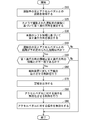
- 5 is a flowchart illustrating an operation of the erroneous start control device and an erroneous start control method according to the first embodiment.
- FIG. 13 is a block diagram illustrating a configuration of an erroneous start control device and a device that operates in connection therewith according to a second embodiment.
- FIG. 1 is a diagram illustrating an example of a processing circuit included in the erroneous start control device according to Embodiment 1.
- FIG. FIG. 5 is a diagram illustrating another example of the processing circuit included in the false start control device according to the first embodiment.
- FIG. 9 is a diagram showing a relationship between a false start control device and a device provided in a vehicle according to a second embodiment.
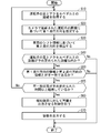
- 8 is a flowchart illustrating an operation of the erroneous start control device and an erroneous start control method according to Embodiment 2.
- FIG. 14 is a block diagram illustrating a configuration of a false start control device and a device that operates in connection therewith in a third embodiment.
- 9 is a flowchart illustrating an operation of the erroneous start control device and an erroneous start control method according to Embodiment 3.
- FIG. 14 is a block diagram showing a configuration of an erroneous start control device and a device that operates in connection therewith in Embodiment 4.
- FIG. 14 is a flowchart illustrating an operation of the erroneous start control device and an erroneous start control method according to Embodiment 4.
- 17 is a flowchart illustrating an operation of the erroneous start control device and an erroneous start control method according to Embodiment 5.
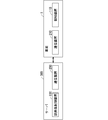
- FIG. 17 is a block diagram showing a configuration of an erroneous start control device and a device that operates in connection therewith in a sixth embodiment.
- FIG. 1 is a block diagram showing a configuration of an erroneous start control device 100 according to Embodiment 1 and a device that operates in connection therewith.
- the erroneous start control device 100 includes a distance acquisition unit 10, a traveling direction acquisition unit 20, and an alarm output control unit 30.
- FIG. 1 shows a notification device 110 as a device that operates in association with the false start control device 100.
- the distance acquisition unit 10 acquires the distance between the driver's foot of the vehicle and the accelerator pedal of the vehicle.
- the distance between the driver's foot of the vehicle and the accelerator pedal of the vehicle is measured by, for example, a distance sensor or a camera for distance measurement.
- the traveling direction acquisition unit 20 acquires information on the first traveling direction and information on the second traveling direction.
- the first traveling direction is the traveling direction of the vehicle estimated based on the driver's image captured by the camera.
- the second traveling direction is a traveling direction of the vehicle detected based on the vehicle shift information.
- the alarm output control unit 30 Is controlled to output an alarm to the notification device 110 provided in the communication device.
- Notification device 110 is provided in the vehicle.
- the notification device 110 outputs an alarm.
- FIG. 2 is a diagram showing an example of the processing circuit 90 included in the false start control device 100.
- Each function of the distance acquisition unit 10, the traveling direction acquisition unit 20, and the alarm output control unit 30 is realized by the processing circuit 90. That is, the processing circuit 90 includes the distance acquisition unit 10, the traveling direction acquisition unit 20, and the alarm output control unit 30.
- the processing circuit 90 When the processing circuit 90 is dedicated hardware, the processing circuit 90 includes, for example, a single circuit, a composite circuit, a programmed processor, a parallel programmed processor, an ASIC (Application Specific Integrated Circuit), and an FPGA (Field-Programmable). Gate Array) or a circuit combining these.
- Each function of the distance acquisition unit 10, the traveling direction acquisition unit 20, and the alarm output control unit 30 may be individually realized by a plurality of processing circuits, or may be realized by one processing circuit.
- FIG. 3 is a diagram showing another example of the processing circuit included in the false start control device 100.
- the processing circuit has a processor 91 and a memory 92.
- the processor 91 executes the program stored in the memory 92, the functions of the distance acquisition unit 10, the traveling direction acquisition unit 20, and the alarm output control unit 30 are realized.
- each function is realized by executing software or firmware described as a program by the processor 91. That is, the erroneous start control device 100 includes a memory 92 that stores a program, and a processor 91 that executes the program.
- the false start control device 100 obtains the distance between the driver's foot of the vehicle and the accelerator pedal of the vehicle, and indicates the traveling direction of the vehicle estimated based on the driver's image captured by the camera.
- the information of the first traveling direction and the information of the second traveling direction which is the traveling direction of the vehicle detected based on the shift information of the vehicle, are acquired, and the distance between the driver's foot and the accelerator pedal is predetermined.
- the program causes the computer to execute the procedure or method of the distance acquisition unit 10, the traveling direction acquisition unit 20, and the alarm output control unit 30.
- the processor 91 is, for example, a central processing unit, a processing unit, an arithmetic unit, a microprocessor, a microcomputer, a DSP (Digital Signal Processor), or the like.
- the memory 92 is a nonvolatile or volatile memory such as a RAM (Random Access Memory), a ROM (Read Only Memory), a flash memory, an EPROM (Erasable Programmable Read Only Memory), and an EEPROM (Electrically Erasable Programmable Read Only Memory). It is a semiconductor memory.
- the memory 92 may be any storage medium used in the future, such as a magnetic disk, a flexible disk, an optical disk, a compact disk, a mini disk, a DVD, and the like.
- the functions of the distance acquisition unit 10, the traveling direction acquisition unit 20, and the alarm output control unit 30 described above may be partially implemented by dedicated hardware and partially implemented by software or firmware.
- the processing circuit realizes the above-described functions by hardware, software, firmware, or a combination thereof.
- FIG. 4 is a flowchart showing the operation of the false start control device 100 and the false start control method according to the first embodiment.
- step S1 the distance acquisition unit 10 acquires the distance between the driver's foot and the accelerator pedal.
- step S2 the traveling direction acquisition unit 20 acquires information on the first traveling direction and information on the second traveling direction.
- step S3 the warning output control unit 30 determines that the distance between the driver's foot and the accelerator pedal is within a predetermined distance, and the information on the first traveling direction and the information on the second traveling direction do not match. Is determined.
- the alarm output control unit 30 has determined that the distance between the driver's foot and the accelerator pedal is within a predetermined distance, and that the information of the first traveling direction and the information of the second traveling direction do not match.
- step S4 is performed.
- the alarm output control unit 30 has determined that the distance between the driver's foot and the accelerator pedal is not within a predetermined distance, or that the information of the first traveling direction and the information of the second traveling direction are not inconsistent. In this case, the false start control method ends.
- step S4 the alarm output control unit 30 controls the alarm device 110 to output an alarm.
- the erroneous start control device 100 includes the distance acquisition unit 10 that acquires the distance between the driver's foot of the vehicle and the accelerator pedal of the vehicle, and the driver's image captured by the camera.
- a traveling direction acquisition unit that acquires information of a first traveling direction that is a traveling direction of a vehicle estimated based on the information and information of a second traveling direction that is a traveling direction of a vehicle detected based on shift information of the vehicle. 20 and the distance between the driver's foot and the accelerator pedal is within a predetermined distance, and the information of the first traveling direction and the information of the second traveling direction do not match each other.
- an alarm output control unit 30 that controls the alarm device 110 to output an alarm.
- the erroneous start control device 100 controls the notification device 110 to output an alarm regarding erroneous start before the driver of the vehicle depresses the accelerator pedal.
- the notification device 110 notifies the driver before the vehicle starts moving.
- the driver recognizes the warning and stops depressing the accelerator pedal. Therefore, the erroneous start control device 100 can accurately prevent erroneous start of the vehicle. Further, when the vehicle moves in a direction opposite to the direction intended by the driver, the driver is surprised by the movement.
- the false start control device 100 can reduce such a driver's burden.
- the false start control method obtains the distance between the driver's foot of the vehicle and the accelerator pedal of the vehicle, and estimates the vehicle based on the driver's image captured by the camera.
- the first traveling direction which is the traveling direction of the vehicle
- information of the second traveling direction which is the traveling direction of the vehicle detected based on the shift information of the vehicle.
- the erroneous start control method causes the notification device 110 to output an alarm indicating the possibility of erroneous start before the driver of the vehicle depresses the accelerator pedal.
- the notification device 110 notifies the driver before the vehicle starts moving.
- the driver recognizes the warning and stops depressing the accelerator pedal. Therefore, the erroneous start control method can accurately prevent erroneous start of the vehicle. Further, when the vehicle moves in a direction opposite to the direction intended by the driver, the driver is surprised by the movement. The false start control method can reduce such a burden on the driver.
- the second embodiment is a subordinate concept of the first embodiment.
- the false start control device according to the second embodiment includes the components of the false start control device 100 shown in the first embodiment. The description of the same configuration and operation as in the first embodiment will be omitted.
- FIG. 5 is a block diagram showing a configuration of the false start control apparatus 101 according to the second embodiment and a device that operates in connection therewith.
- the false start control device 101 includes a distance acquisition unit 10, a traveling direction acquisition unit 20, and an alarm output control unit 30.
- FIG. 5 illustrates a distance sensor 120, a camera 130, a gear 140, and a speaker 111 as devices that operate in association with the false start control device 101.
- FIG. 6 is a diagram showing a relationship between the erroneous start control device 101 and the device provided in the vehicle 1 according to the second embodiment.
- the false start control device 101 is mounted on the vehicle 1.
- Distance sensor 120 is provided in vehicle 1.
- Distance sensor 120 measures the distance between foot 2A of the driver of vehicle 1 and accelerator pedal 150.
- the driver's foot 2A is the foot of the driver 2 and, for example, the sole of the driver 2 who operates the accelerator pedal 150 (that is, the sole of the shoe) or the tip of the foot of the driver 2 (that is, the shoe 2). At the end).
- the distance sensor 120 may be a distance measuring camera.
- the distance acquisition unit 10 acquires the distance between the foot 2A of the driver of the vehicle 1 and the accelerator pedal 150 measured by the distance sensor 120.
- the camera 130 is mounted on the vehicle 1 and captures an image of the driver 2.
- the image of the driver 2 includes, for example, an image of the face of the driver 2 or an image of the eyes of the driver 2.
- the gear 140 is provided on the vehicle 1 and is operated by the shift lever 141.
- the traveling direction acquisition unit 20 acquires the first traveling direction estimated based on the image of the driver 2 captured by the camera 130.
- the traveling direction acquisition unit 20 estimates the first traveling direction by itself, the traveling direction acquisition unit 20 first acquires an image of the face of the driver 2 captured by the camera 130. Then, the traveling direction acquisition unit 20 estimates the first traveling direction based on the direction of the face of the driver 2 or the direction of the line of sight in the image of the driver 2.
- the traveling direction acquisition unit 20 determines that the first traveling direction is forward. presume. Or, for example, when the face or line of sight of the driver 2 is facing the rear of the vehicle 1, when facing the monitor that displays the rear image of the vehicle 1, or when facing the room mirror, the traveling direction is acquired. The unit 20 estimates that the first traveling direction is backward. The first traveling direction estimated in this way corresponds to the traveling direction intended by the driver 2 of the vehicle 1.
- the traveling direction acquisition unit 20 acquires the second traveling direction detected based on the shift information of the vehicle 1.
- the traveling direction obtaining unit 20 may detect the position of the shift lever 141 or the position of the gear 140 as the shift information of the vehicle 1.
- the traveling direction obtaining unit 20 detects the second traveling direction when the shift information is drive or reverse. For example, when the shift information based on the position of the shift lever 141 is drive, the second traveling direction is forward. Alternatively, for example, when the shift information based on the position of the shift lever 141 is reverse, the second traveling direction is backward.
- the second traveling direction detected in this manner corresponds to a direction in which the vehicle 1 travels when driven by a driving device (not shown) of the vehicle 1.
- the second traveling direction corresponds to the traveling direction of the vehicle 1 when the driver 2 depresses the accelerator pedal 150.
- the second traveling direction corresponds to a direction in which the vehicle 1 equipped with the automatic transmission travels due to a creep phenomenon.
- the alarm output control unit 30 determines that the distance between the driver's foot 2A and the accelerator pedal 150 is within a predetermined distance and that the information of the first traveling direction does not match the information of the second traveling direction. Control to output an alarm to the speaker 111.
- the traveling direction obtaining unit 20 does not detect the second traveling direction because there is no possibility of erroneous starting. That is, the warning output control unit 30 does not perform control to output a warning to the notification device 110 when the shift information is neutral or parking, and outputs the notification device 110 when the shift information is drive or reverse. Is controlled to output an alarm.
- the speaker 111 is the notification device 110 and is provided in the vehicle 1.
- the speaker 111 outputs a warning by voice under the control of the warning output control unit 30.
- a display device (not shown) may be provided in the vehicle 1 as the notification device 110, and in that case, the alarm output control unit 30 performs control to display an alarm on the display device.
- FIG. 7 is a flowchart showing the operation of the false start control device 101 and the false start control method according to the second embodiment.
- step S10 the distance acquisition unit 10 acquires the distance between the driver's foot 2A and the accelerator pedal 150 from the distance sensor 120.
- the traveling direction acquisition unit 20 estimates the first traveling direction based on the image of the driver 2 captured by the camera 130.
- the traveling direction acquisition unit 20 estimates the first traveling direction based on the direction of the face or the line of sight of the driver 2 in the image of the driver 2. For example, when the face or line of sight of the driver 2 is facing the front of the vehicle 1 via the windshield of the vehicle 1, the traveling direction acquisition unit 20 estimates that the first traveling direction is forward. Or, for example, when the face or line of sight of the driver 2 is facing the rear of the vehicle 1, when facing the monitor that displays the rear image of the vehicle 1, or when facing the room mirror, the traveling direction is acquired. The unit 20 estimates that the first traveling direction is backward.
- step S30 the traveling direction acquisition unit 20 detects the second traveling direction based on the shift information of the vehicle 1. For example, when the shift information based on the position of the shift lever 141 is drive, the second traveling direction is forward. Alternatively, for example, when the shift information based on the position of the shift lever 141 is reverse, the second traveling direction is backward.
- step S40 the warning output control unit 30 determines whether the distance between the driver's foot 2A and the accelerator pedal 150 is within a predetermined distance.
- step S50 is executed. If the distance is not within the predetermined distance, the false start control method ends.
- step S50 the warning output control unit 30 determines whether the information on the first traveling direction and the information on the second traveling direction do not match. If the information on the first traveling direction and the information on the second traveling direction do not match, there is a high possibility that the vehicle will start erroneously. Therefore, when the information of the first traveling direction does not match the information of the second traveling direction, step S60 is executed. When the information on the first traveling direction matches the information on the second traveling direction, the false start control method ends.
- alarm output control unit 30 controls alarm unit 110 to output an alarm.
- the alarm output control unit 30 controls the speaker 111 to output an alarm.
- step S70 speaker 111 outputs a warning by voice.
- the erroneous start control device 101 described above controls the speaker 111 to output an alarm about erroneous start before the driver 2 of the vehicle 1 depresses the accelerator pedal 150.
- the speaker 111 notifies the driver 2 by voice before the vehicle 1 starts moving.
- the driver 2 recognizes the warning and stops depressing the accelerator pedal 150. Therefore, the erroneous start control device 101 can accurately prevent the erroneous start of the vehicle 1.
- the driver 2 is surprised by the movement.
- the erroneous start control device 101 can reduce such a burden on the driver 2.
- the alarm output control unit 30 of the erroneous start control device 101 performs control to output an alarm when the shift information of the vehicle 1 is drive or reverse.
- the erroneous start control device 101 can accurately prevent the erroneous start of the vehicle 1.
- the third embodiment is a subordinate concept of the first embodiment.
- the erroneous start control device according to the third embodiment includes each configuration of erroneous start control device 100 shown in the first embodiment. The description of the same configuration and operation as those in the first or second embodiment is omitted.
- FIG. 8 is a block diagram showing a configuration of the erroneous start control device 102 according to the third embodiment and a device that operates in connection therewith.
- the erroneous start control device 102 further includes a start control unit 40 in addition to the configuration shown in the second embodiment.
- FIG. 8 further shows an accelerator pedal 150 as a device that operates in association with the false start control device 102.
- the alarm output control unit 30 determines that the distance between the driver's foot 2A and the accelerator pedal 150 is within a predetermined distance, and that the information on the first traveling direction and the second traveling direction Is controlled to output an alarm to the speaker 111 when the information does not match.
- the alarm output control unit 30 in the third embodiment further controls the start control unit 40 to invalidate the operation of the accelerator pedal 150 when outputting the alarm.
- the start control unit 40 has a function of preventing an erroneous operation on the accelerator pedal 150 provided on the vehicle 1.
- the opening of the accelerator pedal 150 is detected by, for example, a position sensor (not shown).
- An engine control unit (ECU) (not shown) of the vehicle 1 controls the output of the engine (not shown) based on the detection result.
- the vehicle 1 is an electric vehicle.
- a power control unit (ECU) (not shown) of the vehicle 1 controls a motor (not shown) based on the detection result of the position sensor.
- the start control unit 40 invalidates the operation of the driver 2 on the accelerator pedal 150 under the control of the alarm output control unit 30.
- the start control unit 40 may be included in, for example, an ECU or a PCU. Alternatively, for example, the start control unit 40 may be a device different from the ECU or the PCU.
- FIG. 9 is a flowchart showing the operation of the false start control device 102 and the false start control method according to the third embodiment.
- Steps up to step S70 are the same as the respective steps shown in FIG.
- step S80 the alarm output control unit 30 controls the start control unit 40 to invalidate the operation on the accelerator pedal 150.
- step S90 start control unit 40 invalidates the operation on accelerator pedal 150.
- the erroneous start control device 102 further includes a start control unit 40 that prevents erroneous operation of the accelerator pedal 150.
- the alarm output control unit 30 controls the start control unit 40 to invalidate the operation on the accelerator pedal 150 when outputting an alarm.
- the false start control device 102 can invalidate the accelerator pedal 150 before the driver 2 of the vehicle 1 depresses the accelerator pedal 150.
- the erroneous start control device 102 can accurately prevent erroneous start of the vehicle 1.
- the fourth embodiment is a subordinate concept of the first embodiment.
- the erroneous start control device according to the fourth embodiment includes the components of erroneous start control device 100 shown in the first embodiment. The description of the same configuration and operation as any of the first to third embodiments will be omitted.
- the first traveling direction does not coincide with the second traveling direction for a short time.
- the second traveling direction is forward.
- the first traveling direction is the rear in a short time of the rear confirmation.
- the speaker 111 outputs an alarm.
- an alarm is output each time the driver 2 confirms behind.
- the driver 2 checks leftward, rightward, or backward to prevent pedestrians from getting involved.
- the false start control device has a configuration that solves such a problem.
- FIG. 10 is a block diagram showing a configuration of the erroneous start control device 103 according to the fourth embodiment and a device that operates in connection therewith.
- the erroneous start control device 103 has a mismatch time measuring unit 31 in the alarm output control unit 30.
- Other configurations of the erroneous start control device 103 are the same as those of the erroneous start control device 101 described in the second embodiment.
- the inconsistency time measuring unit 31 measures a state in which the information in the first traveling direction and the information in the second traveling direction do not coincide, that is, the duration of the inconsistent state.
- the alarm output control unit 30 performs control to output an alarm when the continuation time of the mismatch state measured by the mismatch time measurement unit 31 exceeds a predetermined time.
- FIG. 11 is a flowchart showing an operation of the false start control device 103 and a false start control method according to the fourth embodiment.
- Steps up to step S50 are the same as the respective steps shown in FIG. However, if it is determined in step S50 that the alarm output control unit 30 is in a mismatch state, the alarm output control unit 30 records the time in a storage unit (not shown) of the false start control device 103.
- alarm output control unit 30 determines whether or not the mismatch state has continued for a predetermined time or more. For example, the alarm output control unit 30 determines whether or not the mismatch state has continued for a predetermined time or more based on the time recorded in the storage unit. If the mismatch state continues for a predetermined time or more, step S60 is executed. If the mismatch state has not continued for a predetermined time or more, step S10 is executed again.
- Step S60 and subsequent steps are the same as the respective steps shown in FIG.
- the alarm output control unit 30 of the false start control device 103 has been in a state where the information of the first traveling direction and the information of the second traveling direction do not match for a predetermined time or more. In such a case, control to output an alarm is performed.
- the false start control device 103 can perform control so that an alarm is not output in a short-time mismatch state caused by the driver's 2 confirming operation. As a result, the accuracy of the erroneous start suppression control is improved. Further, the erroneous start control device 103 eliminates the annoyance felt by the driver 2 with respect to an alarm caused by the confirmation operation of the driver 2.
- the fifth embodiment is a subordinate concept of the first embodiment.
- the false start control device according to the fifth embodiment includes the components of false start control device 100 shown in the first embodiment. The description of the same configuration and operation as any of the first to fourth embodiments will be omitted.
- the alarm continues to sound. For example, even when the driver 2 does not try to depress the accelerator pedal 150, if the state where the driver's foot 2A is close to the accelerator pedal 150 continues, the alarm continues to sound. Alternatively, for example, even when the position of the driver's foot 2A is close to the accelerator pedal 150 in the normal position of the driver 2, an alarm sounds. In order to improve the accuracy of the erroneous start suppression control, it is preferable that the frequency of alarm output be low in such a situation.
- the false start control device has a configuration for solving such a problem.
- the configuration of the erroneous start control device according to the fifth embodiment is similar to that of the erroneous start control device 101 according to the second embodiment.
- FIG. 12 is a flowchart showing the operation of the false start control device and the false start control method according to the fifth embodiment.
- Steps up to step S40 are the same as the respective steps shown in FIG. However, in step S40, when the alarm output control unit 30 determines that the distance between the driver's foot 2A and the accelerator pedal 150 is within a predetermined distance, the alarm output control unit 30 performs the erroneous start control. The distance between the driver's foot 2A and the accelerator pedal 150 is recorded in a storage unit of the device.
- step S45 the warning output control unit 30 determines whether or not the distance between the driver's foot 2A and the accelerator pedal 150 is approaching. For example, the alarm output control unit 30 reads the distance recorded in the storage unit, that is, the previously acquired distance. Then, the alarm output control unit 30 determines whether the driver's foot 2A is approaching the accelerator pedal 150 based on the previously acquired distance and the currently acquired distance. If the distance is approaching, step S50 is executed. If the distance is not approaching, step S10 is executed again.
- Step S50 and subsequent steps are the same as the respective steps shown in FIG.
- the alarm output control unit 30 of the erroneous start control device controls to output an alarm when the distance between the driver's foot 2A and the accelerator pedal 150 is approaching over time. I do.
- the erroneous start control device can perform control so that an alarm that is caused by the position of the driver's foot 2A and is not intended by the driver 2 is not output. As a result, the accuracy of the erroneous start suppression control is improved.
- the erroneous start control device eliminates the inconvenience felt by the driver 2 with respect to an unnecessary alarm caused by the position of the driver's foot 2A.
- the erroneous start control device shown in each of the above embodiments can be applied to a system constructed by appropriately combining the navigation device, the communication terminal, the server, and the functions of the applications installed therein.
- the navigation device includes, for example, a PND (Portable Navigation Device).
- the communication terminal includes, for example, a mobile terminal such as a mobile phone, a smartphone, and a tablet.
- FIG. 13 is a block diagram showing a configuration of an erroneous start control device 100 according to Embodiment 6 and a device operating in connection therewith.
- the erroneous start control device 100 and the communication device 200 are provided in the server 300.
- the erroneous start control device 100 includes information on the distance between the driver's foot and the accelerator pedal, the first traveling direction information, and the second Get information on the direction of travel.
- the erroneous start control device 100 informs when the distance between the driver's foot and the accelerator pedal is within a predetermined distance and the information on the first traveling direction does not match the information on the second traveling direction.
- the control to output an alarm to the device 110 is performed. At that time, the erroneous start control device 100 controls the notification device 110 to output an alarm via each communication device.
- the configuration of the vehicle-mounted device can be simplified.
- some of the functions or components of the erroneous start control device 100 may be provided in the server 300 and the other part may be provided in the vehicle 1, for example, in a distributed manner.
- each embodiment can be freely combined, or each embodiment can be appropriately modified or omitted within the scope of the invention.
Landscapes
- Engineering & Computer Science (AREA)
- General Engineering & Computer Science (AREA)
- Mechanical Engineering (AREA)
- Chemical & Material Sciences (AREA)
- Combustion & Propulsion (AREA)
- Transportation (AREA)
- Physics & Mathematics (AREA)
- General Physics & Mathematics (AREA)
- Auxiliary Drives, Propulsion Controls, And Safety Devices (AREA)
- Traffic Control Systems (AREA)
- Control Of Driving Devices And Active Controlling Of Vehicle (AREA)
- Control Of Transmission Device (AREA)
Abstract
車両の誤発進を正確に防止する誤発進制御装置の提供を目的とする。誤発進制御装置は、車両の運転手の足と車両のアクセルペダルとの距離を取得する距離取得部と、カメラで撮影された運転手の画像に基づいて推定される車両の進行方向である第1進行方向の情報と、車両のシフト情報に基づいて検出される車両の進行方向である第2進行方向の情報と、を取得する進行方向取得部と、運転手の足とアクセルペダルとの距離が予め定められた距離以内であり、かつ、第1進行方向の情報と第2進行方向の情報とが一致しない場合に、車両に設けられた報知装置に対して警報を出力させる制御を行う警報出力制御部と、を含む。
Description
本発明は、誤発進制御装置および誤発進制御方法に関する。
特許文献1に記載の車両の誤発進防止装置は、運転手が意図する進行方向とギア切替位置に基づく車両の進行方向とが一致しているかどうか判定する。それらの進行方向が一致していない場合は、誤発進防止装置は、車両の発進を阻止するとともに運転手に対し警告を発する。
特許文献1の誤発進防止装置は、アクセル操作が行われた場合、または車両が動いている場合に、アクセル操作を無効にする。その一方で、特許文献1には、アクセル操作を行う前もしくは車両が停止している状態での誤発進防止動作に関して記載がない。その誤発進防止の制御は、運転手が意図する進行方向とは逆方向に車両が発進した後に、実行される。そのような誤発進の抑制制御は、正確性に劣る。
本発明は、以上のような課題を解決するためになされたものであり、車両の誤発進を正確に防止する誤発進制御装置の提供を目的とする。
本発明に係る誤発進制御装置は、車両の運転手の足と車両のアクセルペダルとの距離を取得する距離取得部と、カメラで撮影された運転手の画像に基づいて推定される車両の進行方向である第1進行方向の情報と、車両のシフト情報に基づいて検出される車両の進行方向である第2進行方向の情報と、を取得する進行方向取得部と、運転手の足とアクセルペダルとの距離が予め定められた距離以内であり、かつ、第1進行方向の情報と第2進行方向の情報とが一致しない場合に、車両に設けられた報知装置に対して警報を出力させる制御を行う警報出力制御部と、を含む。
本発明によれば、車両の誤発進を正確に防止する誤発進制御装置の提供が可能である。
本発明の目的、特徴、局面、および利点は、以下の詳細な説明と添付図面とによって、より明白になる。
<実施の形態1>
図1は、実施の形態1における誤発進制御装置100およびそれに関連して動作する装置の構成を示すブロック図である。
図1は、実施の形態1における誤発進制御装置100およびそれに関連して動作する装置の構成を示すブロック図である。
誤発進制御装置100は、距離取得部10、進行方向取得部20および警報出力制御部30を有する。また、図1には、誤発進制御装置100に関連して動作する装置として、報知装置110が示されている。
距離取得部10は、車両の運転手の足と車両のアクセルペダルとの距離を取得する。車両の運転手の足と車両のアクセルペダルとの距離は、例えば、距離センサまたは距離測定用のカメラによって測定される。
進行方向取得部20は、第1進行方向の情報と第2進行方向の情報とを取得する。第1進行方向とは、カメラで撮影された運転手の画像に基づいて推定される車両の進行方向である。第2進行方向とは、車両のシフト情報に基づいて検出される車両の進行方向である。
警報出力制御部30は、運転手の足とアクセルペダルとの距離が予め定められた距離以内であり、かつ、第1進行方向の情報と第2進行方向の情報とが一致しない場合に、車両に設けられた報知装置110に対して警報を出力させる制御を行う。
報知装置110は、車両に設けられている。報知装置110は、警報を出力する。
図2は、誤発進制御装置100が有する処理回路90の一例を示す図である。距離取得部10、進行方向取得部20および警報出力制御部30の各機能は、処理回路90により実現される。すなわち、処理回路90は、距離取得部10、進行方向取得部20および警報出力制御部30を有する。
処理回路90が専用のハードウェアである場合、処理回路90は、例えば、単一回路、複合回路、プログラム化したプロセッサ、並列プログラム化したプロセッサ、ASIC(Application Specific Integrated Circuit)、FPGA(Field-Programmable Gate Array)、またはこれらを組み合わせた回路等である。距離取得部10、進行方向取得部20および警報出力制御部30の各機能は、複数の処理回路により個別に実現されてもよいし、1つの処理回路によりまとめて実現されてもよい。
図3は、誤発進制御装置100が有する処理回路の別の一例を示す図である。処理回路は、プロセッサ91とメモリ92とを有する。プロセッサ91がメモリ92に格納されるプログラムを実行することにより、距離取得部10、進行方向取得部20および警報出力制御部30の各機能が実現される。例えば、プログラムとして記述されたソフトウェアまたはファームウェアがプロセッサ91により実行されることにより各機能が実現される。すなわち、誤発進制御装置100は、プログラムを格納するメモリ92と、そのプログラムを実行するプロセッサ91とを有する。
プログラムには、誤発進制御装置100が、車両の運転手の足と車両のアクセルペダルとの距離を取得し、カメラで撮影された運転手の画像に基づいて推定される車両の進行方向である第1進行方向の情報と、車両のシフト情報に基づいて検出される車両の進行方向である第2進行方向の情報と、を取得し、運転手の足とアクセルペダルとの距離が予め定められた距離以内であり、かつ、第1進行方向の情報と第2進行方向の情報とが一致しない場合に、車両に設けられた報知装置110に対して警報を出力させる制御を行う機能が記述されている。また、プログラムは、距離取得部10、進行方向取得部20および警報出力制御部30の手順または方法をコンピュータに実行させるものである。
プロセッサ91は、例えば、中央処理装置、処理装置、演算装置、マイクロプロセッサ、マイクロコンピュータ、DSP(Digital Signal Processor)等である。メモリ92は、例えば、RAM(Random Access Memory)、ROM(Read Only Memory)、フラッシュメモリ、EPROM(Erasable Programmable Read Only Memory)、EEPROM(Electrically Erasable Programmable Read Only Memory)等の、不揮発性または揮発性の半導体メモリである。または、メモリ92は、磁気ディスク、フレキシブルディスク、光ディスク、コンパクトディスク、ミニディスク、DVD等、今後使用されるあらゆる記憶媒体であってもよい。
上述した距離取得部10、進行方向取得部20および警報出力制御部30の各機能は、一部が専用のハードウェアによって実現され、他の一部がソフトウェアまたはファームウェアにより実現されてもよい。このように、処理回路は、ハードウェア、ソフトウェア、ファームウェア、またはこれらの組み合わせによって、上述の各機能を実現する。
図4は、実施の形態1における誤発進制御装置100の動作および誤発進制御方法を示すフローチャートである。
ステップS1にて、距離取得部10は、運転手の足とアクセルペダルとの距離を取得する。
ステップS2にて、進行方向取得部20は、第1進行方向の情報と第2進行方向の情報とを取得する。
ステップS3にて、警報出力制御部30は、運転手の足とアクセルペダルとの距離が予め定められた距離以内であり、かつ、第1進行方向の情報と第2進行方向の情報とが不一致であるか否かを判定する。警報出力制御部30が、運転手の足とアクセルペダルとの距離が予め定められた距離以内であり、かつ、第1進行方向の情報と第2進行方向の情報とが不一致であると判定した場合、ステップS4が実行される。警報出力制御部30が、運転手の足とアクセルペダルとの距離が予め定められた距離以内ではない、または、第1進行方向の情報と第2進行方向の情報とが不一致ではないと判定した場合、誤発進制御方法は終了する。
ステップS4にて、警報出力制御部30は、報知装置110に対して警報を出力させる制御を行う。
以上をまとめると、実施の形態1における誤発進制御装置100は、車両の運転手の足と車両のアクセルペダルとの距離を取得する距離取得部10と、カメラで撮影された運転手の画像に基づいて推定される車両の進行方向である第1進行方向の情報と、車両のシフト情報に基づいて検出される車両の進行方向である第2進行方向の情報と、を取得する進行方向取得部20と、運転手の足とアクセルペダルとの距離が予め定められた距離以内であり、かつ、第1進行方向の情報と第2進行方向の情報とが一致しない場合に、車両に設けられた報知装置110に対して警報を出力させる制御を行う警報出力制御部30と、を含む。
以上の構成により、誤発進制御装置100は、車両の運転手がアクセルペダルを踏み込む前に、報知装置110が誤発進に関する警報を出力するよう制御する。報知装置110は、車両が動き出す前に運転手に対し報知する。運転手は、その警報を認知し、アクセルペダルを踏み込む動作を止める。そのため、誤発進制御装置100は、車両の誤発進を正確に防止することが可能である。また、車両が運転手の意図する方向とは逆方向に動いた場合、運転手はその動きに驚いてしまう。誤発進制御装置100は、そのような運転手の負担を軽減することができる。
以上をまとめると、実施の形態1における誤発進制御方法は、車両の運転手の足と車両のアクセルペダルとの距離を取得し、カメラで撮影された運転手の画像に基づいて推定される車両の進行方向である第1進行方向の情報と、車両のシフト情報に基づいて検出される車両の進行方向である第2進行方向の情報と、を取得し、運転手の足とアクセルペダルとの距離が予め定められた距離以内であり、かつ、第1進行方向の情報と第2進行方向の情報とが一致しない場合に、車両に設けられた報知装置110に対して警報を出力させる制御を行う。
以上の構成により、誤発進制御方法は、車両の運転手がアクセルペダルを踏み込む前に、誤発進の可能性の警報を報知装置110に出力させる。報知装置110は、車両が動き出す前に運転手に対し報知する。運転手は、その警報を認知し、アクセルペダルを踏み込む動作を止める。そのため、誤発進制御方法は、車両の誤発進を正確に防止することが可能である。また、車両が運転手の意図する方向とは逆方向に動いた場合、運転手はその動きに驚いてしまう。誤発進制御方法は、そのような運転手の負担を軽減することができる。
<実施の形態2>
実施の形態2における誤発進制御装置および誤発進制御方法を説明する。実施の形態2は、実施の形態1の下位概念である。実施の形態2における誤発進制御装置は、実施の形態1において示された誤発進制御装置100の各構成を含む。なお、実施の形態1と同様の構成および動作については説明を省略する。
実施の形態2における誤発進制御装置および誤発進制御方法を説明する。実施の形態2は、実施の形態1の下位概念である。実施の形態2における誤発進制御装置は、実施の形態1において示された誤発進制御装置100の各構成を含む。なお、実施の形態1と同様の構成および動作については説明を省略する。
図5は、実施の形態2における誤発進制御装置101およびそれに関連して動作する装置の構成を示すブロック図である。誤発進制御装置101は、距離取得部10、進行方向取得部20および警報出力制御部30を有する。また、図5には、誤発進制御装置101に関連して動作する装置として、距離センサ120、カメラ130、ギア140およびスピーカ111が示されている。
図6は、実施の形態2における誤発進制御装置101と車両1に設けられる装置との関係を示す図である。ここでは、誤発進制御装置101は、車両1に搭載されている。
距離センサ120は、車両1に設けられている。距離センサ120は、車両1の運転手の足2Aとアクセルペダル150との距離を測定する。運転手の足2Aとは、運転手2の足元のことであり、例えば、アクセルペダル150を操作する運転手2の足の裏(すなわち靴の裏)または運転手2の足の先(すなわち靴の先)である。距離センサ120は、距離測定用カメラであってもよい。
距離取得部10は、距離センサ120にて測定された車両1の運転手の足2Aとアクセルペダル150との距離を取得する。
カメラ130は、車両1に搭載されており、運転手2の画像を撮影する。運転手2の画像は、例えば、運転手2の顔の画像、または、運転手2の目の画像を含む。
ギア140は、車両1に設けられ、シフトレバー141によって操作される。
進行方向取得部20は、カメラ130で撮影された運転手2の画像に基づいて推定される第1進行方向を取得する。進行方向取得部20が自ら第1進行方向を推定する場合、進行方向取得部20は、まず、カメラ130で撮影された運転手2の顔の画像を取得する。そして、進行方向取得部20は、運転手2の画像における運転手2の顔の向き、または、視線の向きに基づき、第1進行方向を推定する。
例えば、運転手2の顔または視線が、車両1のフロントガラス(図示せず)を介して車両1の前方を向いている場合、進行方向取得部20は、第1進行方向が前方であると推定する。または、例えば、運転手2の顔または視線が、車両1の後方を向いている場合、車両1の後方映像を映すモニターを向いている場合、あるいは、ルームミラーを向いている場合、進行方向取得部20は、第1進行方向が後方であると推定する。このように推定された第1進行方向は、車両1の運転手2が意図する進行方向に対応する。
また、進行方向取得部20は、車両1のシフト情報に基づいて検出される第2進行方向を取得する。進行方向取得部20は、車両1のシフト情報として、シフトレバー141の位置を検出してもよいし、ギア140の位置を検出してもよい。
実施の形態2において、進行方向取得部20は、シフト情報がドライブまたはリバースである場合に、第2進行方向を検出する。例えば、シフトレバー141の位置に基づくシフト情報がドライブである場合、第2進行方向は前方である。または、例えば、シフトレバー141の位置に基づくシフト情報がリバースである場合、第2進行方向は後方である。このように検出された第2進行方向は、車両1の駆動装置(図示せず)が駆動することにより車両1が進行する方向に対応する。例えば、第2進行方向は、運転手2がアクセルペダル150を踏み込んだ場合に、車両1が進行する方向に対応する。または、例えば、第2進行方向は、オートマチックトランスミッションを搭載する車両1がクリープ現象により進行する方向に対応する。
警報出力制御部30は、運転手の足2Aとアクセルペダル150との距離が予め定められた距離以内であり、かつ、第1進行方向の情報と第2進行方向の情報とが一致しない場合に、スピーカ111に対して警報を出力させる制御を行う。
上記の進行方向取得部20は、シフトレバー141の位置に基づくシフト情報がニュートラルまたはパーキングである場合には、誤発進の可能性がないため、第2進行方向を検出しない。すなわち、警報出力制御部30は、シフト情報がニュートラルまたはパーキングである場合には、報知装置110に対して警報を出力させる制御を行わず、シフト情報がドライブまたはリバースである場合に、報知装置110に対して警報を出力させる制御を行う。
スピーカ111は、報知装置110であり、車両1に設けられている。スピーカ111は、警報出力制御部30の制御により、警報を音声で出力する。また、報知装置110として表示装置(図示せず)が車両1に設けられていてもよく、その場合、警報出力制御部30は、表示装置に対して警報を表示させる制御を行う。
図7は、実施の形態2における誤発進制御装置101の動作および誤発進制御方法を示すフローチャートである。
ステップS10にて、距離取得部10は、距離センサ120から運転手の足2Aとアクセルペダル150との距離を取得する。
ステップS20にて、進行方向取得部20は、カメラ130で撮影された運転手2の画像に基づいて第1進行方向を推定する。進行方向取得部20は、運転手2の画像における運転手2の顔の向きまたは視線の向きに基づき、第1進行方向を推定する。例えば、運転手2の顔または視線が、車両1のフロントガラスを介して車両1の前方を向いている場合、進行方向取得部20は、第1進行方向が前方であると推定する。または、例えば、運転手2の顔または視線が、車両1の後方を向いている場合、車両1の後方映像を映すモニターを向いている場合、あるいは、ルームミラーを向いている場合、進行方向取得部20は、第1進行方向が後方であると推定する。
ステップS30にて、進行方向取得部20は、車両1のシフト情報に基づいて第2進行方向を検出する。例えば、シフトレバー141の位置に基づくシフト情報がドライブである場合、第2進行方向は前方である。または、例えば、シフトレバー141の位置に基づくシフト情報がリバースである場合、第2進行方向は後方である。
ステップS40にて、警報出力制御部30は、運転手の足2Aとアクセルペダル150との距離が予め定められた距離以内か否かを判定する。運転手の足2Aとアクセルペダル150との距離が予め定められた距離以内である場合、運転手2がアクセルペダル150を踏み込む可能性が高い。よって、その距離が予め定められた距離以内である場合、ステップS50が実行される。その距離が予め定められた距離以内でない場合、誤発進制御方法は終了する。
ステップS50にて、警報出力制御部30は、第1進行方向の情報と第2進行方向の情報とが不一致であるか否かを判定する。第1進行方向の情報と第2進行方向の情報とが一致しない場合、車両が誤発進する可能性が高い。よって、第1進行方向の情報と第2進行方向の情報とが一致しない場合、ステップS60が実行される。第1進行方向の情報と第2進行方向の情報とが一致する場合、誤発進制御方法は、終了する。
ステップS60にて、警報出力制御部30は、報知装置110に対して警報を出力させる制御を行う。ここでは、警報出力制御部30は、スピーカ111に対して、警報を出力させる制御を行う。
ステップS70にて、スピーカ111は、警報を音声で出力する。
以上に示された、誤発進制御装置101は、車両1の運転手2がアクセルペダル150を踏み込む前に、スピーカ111が誤発進に関する警報を出力するよう制御する。スピーカ111は、車両1が動き出す前に運転手2に対し音声で報知する。運転手2は、その警報を認知し、アクセルペダル150を踏み込む動作を止める。そのため、誤発進制御装置101は、車両1の誤発進を正確に防止することが可能である。また、車両1が運転手2の意図する方向とは逆方向に動いた場合、運転手2はその動きに驚いてしまう。誤発進制御装置101は、そのような運転手2の負担を軽減することができる。
また、実施の形態2における誤発進制御装置101の警報出力制御部30は、車両1のシフト情報がドライブまたはリバースである場合に、警報を出力させる制御を行う。
このような構成により、誤発進制御装置101は、車両1の誤発進を正確に防止することが可能である。
<実施の形態3>
実施の形態3における誤発進制御装置および誤発進制御方法を説明する。実施の形態3は、実施の形態1の下位概念である。実施の形態3における誤発進制御装置は、実施の形態1において示された誤発進制御装置100の各構成を含む。なお、実施の形態1または2と同様の構成および動作については説明を省略する。
実施の形態3における誤発進制御装置および誤発進制御方法を説明する。実施の形態3は、実施の形態1の下位概念である。実施の形態3における誤発進制御装置は、実施の形態1において示された誤発進制御装置100の各構成を含む。なお、実施の形態1または2と同様の構成および動作については説明を省略する。
図8は、実施の形態3における誤発進制御装置102およびそれに関連して動作する装置の構成を示すブロック図である。
誤発進制御装置102は、実施の形態2に示された構成に加え、発進制御部40をさらに有する。また、図8には、誤発進制御装置102に関連して動作する装置として、アクセルペダル150がさらに示されている。
警報出力制御部30は、実施の形態2と同様に、運転手の足2Aとアクセルペダル150との距離が予め定められた距離以内であり、かつ、第1進行方向の情報と第2進行方向の情報とが一致しない場合に、スピーカ111に対して警報を出力させる制御を行う。実施の形態3における警報出力制御部30は、その警報を出力させる際に、発進制御部40がアクセルペダル150の操作を無効化するよう、さらに制御する。
発進制御部40は、車両1に設けられたアクセルペダル150に対する誤操作を防止する機能を有する。アクセルペダル150の開度は、例えば、ポジションセンサ(図示せず)によって検知される。車両1のエンジンコントロールユニット(ECU)(図示せず)は、その検知結果に基づき、エンジン(図示せず)の出力を制御する。車両1が電気自動車の場合も同様であり、例えば、車両1のパワーコントロールユニット(ECU)(図示せず)が、ポジションセンサの検知結果に基づき、モータ(図示せず)を制御する。発進制御部40は、警報出力制御部30の制御により、アクセルペダル150に対する運転手2の操作を無効化する。そのため、発進制御部40の制御によって、アクセルペダル150が踏み込まれた場合であっても、ECUはエンジンの出力を上げない。このように、発進制御部40は、アクセルペダル150に対する誤操作を防止する。発進制御部40は、例えば、ECUまたはPCUに含まれていてもよい。または、例えば、発進制御部40は、ECUまたはPCUとは別の装置であってもよい。
図9は、実施の形態3における誤発進制御装置102の動作および誤発進制御方法を示すフローチャートである。
ステップS70までは、図7に示された各ステップと同様である。
ステップS80にて、警報出力制御部30は、発進制御部40に対して、アクセルペダル150に対する操作を無効化させる制御を行う。
ステップS90にて、発進制御部40は、アクセルペダル150に対する操作を無効化する。
以上をまとめると、実施の形態3における誤発進制御装置102は、アクセルペダル150に対する誤操作を防止する発進制御部40さらに含む。警報出力制御部30は、警報を出力させる際に、発進制御部40に対してアクセルペダル150に対する操作を無効化させる制御を行う。
以上の構成により、誤発進制御装置102は、車両1の運転手2がアクセルペダル150を踏み込む前に、アクセルペダル150を無効化できる。誤発進制御装置102は、車両1の誤発進を正確に防止することが可能である。
<実施の形態4>
実施の形態4における誤発進制御装置および誤発進制御方法を説明する。実施の形態4は、実施の形態1の下位概念である。実施の形態4における誤発進制御装置は、実施の形態1において示された誤発進制御装置100の各構成を含む。なお、実施の形態1から3のいずれかと同様の構成および動作については説明を省略する。
実施の形態4における誤発進制御装置および誤発進制御方法を説明する。実施の形態4は、実施の形態1の下位概念である。実施の形態4における誤発進制御装置は、実施の形態1において示された誤発進制御装置100の各構成を含む。なお、実施の形態1から3のいずれかと同様の構成および動作については説明を省略する。
運転手2の意図的な動作により、短時間だけ第1進行方向と第2進行方向とが一致しない状態が発生する場合がある。例えば、シフト情報がドライブである場合、第2進行方向は前方である。その状態で運転手2が後方を確認した場合、その後方確認の短時間において、第1進行方向は後方である。後方確認時、第1進行方向と第2進行方向とは一致しないため、スピーカ111は警報を出力する。誤発進制御装置がこのような制御を行うと、運転手2が後方を確認する度に、警報が出力される。また、同様に、左折または右折の際、歩行者等の巻き込み防止のため、運転手2は、左方向の確認、右方向の確認または後方の確認を行う。その場合も、運転手2の確認動作に起因する第1進行方向と第2進行方向の不一致が発生し、警報が出力される。特に、車両1がマニュアルトランスミッションを搭載する場合、上記の課題が顕著に生じる。誤発進の抑制制御の正確性向上のためには、運転手2の意図的な確認動作による警報出力の頻度は少ないほうが好ましい。実施の形態4における誤発進制御装置は、このような課題を解決する構成を有する。
図10は、実施の形態4における誤発進制御装置103およびそれに関連して動作する装置の構成を示すブロック図である。
誤発進制御装置103は、警報出力制御部30に不一致時間計測部31を有する。誤発進制御装置103が有するその他の構成は、実施の形態2に示された誤発進制御装置101と同様である。
不一致時間計測部31は、第1進行方向の情報と第2進行方向の情報とが一致しない状態、つまり不一致状態の継続時間を計測する。
警報出力制御部30は、不一致時間計測部31によって計測された不一致状態の継続時間が、予め定められた時間以上経過した場合に、警報を出力させる制御を行う。
図11は、実施の形態4における誤発進制御装置103の動作および誤発進制御方法を示すフローチャートである。
ステップS50までは、図7に示された各ステップと同様である。ただし、ステップS50にて、警報出力制御部30が不一致状態であると判定した場合、警報出力制御部30は誤発進制御装置103が有する記憶部(図示せず)に時間を記録する。
ステップS55にて、警報出力制御部30は、不一致状態が予め定められた時間以上継続しているか否かを判定する。例えば、警報出力制御部30は、記憶部に記録された時間に基づき、不一致状態が予め定められた時間以上継続しているか否か判定する。不一致状態が予め定められた時間以上継続している場合、ステップS60が実行される。不一致状態が予め定められた時間以上継続していない場合、ステップS10が再び実行される。
ステップS60以降は、図7に示された各ステップと同様である。
以上をまとめると、実施の形態4における誤発進制御装置103の警報出力制御部30は、第1進行方向の情報と第2進行方向の情報とが一致しない状態が予め定められた時間以上継続した場合に、警報を出力させる制御を行う。
以上の構成により、誤発進制御装置103は、運転手2の確認動作に起因するような短時間の不一致状態においては、警報が出力されないように制御することができる。その結果、誤発進の抑制制御の正確性が向上する。また、誤発進制御装置103は、運転手2の確認動作に起因する警報に対し運転手2が感じる煩わしさを解消する。
<実施の形態5>
実施の形態5における誤発進制御装置および誤発進制御方法を説明する。実施の形態5は、実施の形態1の下位概念である。実施の形態5における誤発進制御装置は、実施の形態1において示された誤発進制御装置100の各構成を含む。なお、実施の形態1から4のいずれかと同様の構成および動作については説明を省略する。
実施の形態5における誤発進制御装置および誤発進制御方法を説明する。実施の形態5は、実施の形態1の下位概念である。実施の形態5における誤発進制御装置は、実施の形態1において示された誤発進制御装置100の各構成を含む。なお、実施の形態1から4のいずれかと同様の構成および動作については説明を省略する。
運転手の足2Aとアクセルペダル150との距離が、予め定められた距離以内である状態が継続した場合、警報が鳴り続ける。例えば、運転手2がアクセルペダル150を踏み込もうとしていない場合であっても、運転手の足2Aがアクセルペダル150に近い状態が継続した場合、警報が鳴り続ける。または、例えば、運転手2の通常の構えにおいて、運転手の足2Aの位置がアクセルペダル150に近い状態である場合であっても、警報が鳴る。誤発進の抑制制御の正確性向上のためには、このような状況では警報出力の頻度は少ないほうが好ましい。実施の形態5における誤発進制御装置は、このような課題を解決する構成を有する。
実施の形態5における誤発進制御装置の構成は、実施の形態2において示された誤発進制御装置101と同様である。
図12は、実施の形態5における誤発進制御装置の動作および誤発進制御方法を示すフローチャートである。
ステップS40までは、図7に示された各ステップと同様である。ただし、ステップS40にて、警報出力制御部30が、運転手の足2Aとアクセルペダル150との距離が予め定められた距離以内であると判定した場合、警報出力制御部30は、誤発進制御装置が有する記憶部に、その運転手の足2Aとアクセルペダル150との距離を記録する。
ステップS45にて、警報出力制御部30は、運転手の足2Aとアクセルペダル150との距離が近づいているか否かを判定する。例えば、警報出力制御部30は、記憶部に記録された距離、すなわち前回取得した距離を読み込む。そして、警報出力制御部30は、前回取得した距離と、今回取得した距離とに基づき、その運転手の足2Aがアクセルペダル150に近づいているか否か判定する。その距離が近づいている場合、ステップS50が実行される。その距離が近づいていない場合、ステップS10が再び実行される。
ステップS50以降は、図7に示された各ステップと同様である。
以上をまとめると、実施の形態4における誤発進制御装置の警報出力制御部30は、運転手の足2Aとアクセルペダル150との距離が時間の経過とともに近づいている場合に、警報を出力させる制御を行う。
以上の構成により、誤発進制御装置は、運転手の足2Aの位置に起因した警報であって、運転手2が意図しない警報は出力されないように制御することができる。その結果、誤発進の抑制制御の正確性が向上する。誤発進制御装置は、運転手の足2Aの位置に起因する不要な警報に対し運転手2が感じる煩わしさを解消する。
<実施の形態6>
以上の各実施の形態に示された誤発進制御装置は、ナビゲーション装置と、通信端末と、サーバと、これらにインストールされるアプリケーションの機能とを適宜に組み合わせて構築されるシステムにも適用することができる。ここで、ナビゲーション装置とは、例えば、PND(Portable Navigation Device)などを含む。通信端末とは、例えば、携帯電話、スマートフォンおよびタブレットなどの携帯端末を含む。
以上の各実施の形態に示された誤発進制御装置は、ナビゲーション装置と、通信端末と、サーバと、これらにインストールされるアプリケーションの機能とを適宜に組み合わせて構築されるシステムにも適用することができる。ここで、ナビゲーション装置とは、例えば、PND(Portable Navigation Device)などを含む。通信端末とは、例えば、携帯電話、スマートフォンおよびタブレットなどの携帯端末を含む。
図13は、実施の形態6における誤発進制御装置100およびそれに関連して動作する装置の構成を示すブロック図である。
誤発進制御装置100および通信装置200がサーバ300に設けられている。誤発進制御装置100は、車両1に設けられた誤発進制御装置100から通信装置210および通信装置200を介して運転手の足とアクセルペダルとの距離、第1進行方向の情報、および第2進行方向の情報を取得する。誤発進制御装置100は、運転手の足とアクセルペダルとの距離が予め定められた距離以内であり、かつ、第1進行方向の情報と第2進行方向の情報とが一致しない場合に、報知装置110に対して警報を出力させる制御を行う。その際、誤発進制御装置100は、報知装置110に対し、各通信装置を介して警報を出力させる制御を行う。
このように、誤発進制御装置100がサーバ300に配置されることにより、車載装置の構成を簡素化することができる。
また、誤発進制御装置100の機能あるいは構成要素の一部がサーバ300に設けられ、他の一部が車両1に設けられるなど、分散して配置されてもよい。
なお、本発明は、その発明の範囲内において、各実施の形態を自由に組み合わせたり、各実施の形態を適宜、変形、省略したりすることが可能である。
本発明は詳細に説明されたが、上記した説明は、全ての局面において、例示であって、本発明がそれに限定されるものではない。例示されていない無数の変形例が、この発明の範囲から外れることなく想定され得るものと解される。
1 車両、2 運転手、2A 運転手の足、10 距離取得部、20 進行方向取得部、30 警報出力制御部、31 不一致時間計測部、40 発進制御部、100 誤発進制御装置、101 誤発進制御装置、102 誤発進制御装置、103 誤発進制御装置、110 報知装置、111 スピーカ、120 距離センサ、130 カメラ、140 ギア、141 シフトレバー、150 アクセルペダル。
Claims (6)
- 車両の運転手の足と前記車両のアクセルペダルとの距離を取得する距離取得部と、
カメラで撮影された前記運転手の画像に基づいて推定される前記車両の進行方向である第1進行方向の情報と、前記車両のシフト情報に基づいて検出される前記車両の進行方向である第2進行方向の情報と、を取得する進行方向取得部と、
前記運転手の足と前記アクセルペダルとの前記距離が予め定められた距離以内であり、かつ、前記第1進行方向の情報と前記第2進行方向の情報とが一致しない場合に、前記車両に設けられた報知装置に対して警報を出力させる制御を行う警報出力制御部と、を備える誤発進制御装置。 - 前記アクセルペダルに対する誤操作を防止する発進制御部さらに備え、
前記警報出力制御部は、前記警報を出力させる際に、前記発進制御部に対して前記アクセルペダルに対する操作を無効化させる制御を行う、請求項1に記載の誤発進制御装置。 - 前記警報出力制御部は、前記第1進行方向の情報と前記第2進行方向の情報とが一致しない状態が予め定められた時間以上継続した場合に、前記警報を出力させる制御を行う、請求項1に記載の誤発進制御装置。
- 前記警報出力制御部は、前記運転手の足と前記アクセルペダルとの前記距離が時間の経過とともに近づいている場合に、前記警報を出力させる制御を行う、請求項1に記載の誤発進制御装置。
- 前記警報出力制御部は、前記車両の前記シフト情報がドライブまたはリバースである場合に、前記警報を出力させる制御を行う、請求項1に記載の誤発進制御装置。
- 車両の運転手の足と前記車両のアクセルペダルとの距離を取得し、
カメラで撮影された前記運転手の画像に基づいて推定される前記車両の進行方向である第1進行方向の情報と、前記車両のシフト情報に基づいて検出される前記車両の進行方向である第2進行方向の情報と、を取得し、
前記運転手の足と前記アクセルペダルとの前記距離が予め定められた距離以内であり、かつ、前記第1進行方向の情報と前記第2進行方向の情報とが一致しない場合に、前記車両に設けられた報知装置に対して警報を出力させる制御を行う、誤発進制御方法。
Priority Applications (2)
| Application Number | Priority Date | Filing Date | Title |
|---|---|---|---|
| PCT/JP2018/027653 WO2020021621A1 (ja) | 2018-07-24 | 2018-07-24 | 誤発進制御装置および誤発進制御方法 |
| JP2020531863A JP6942255B2 (ja) | 2018-07-24 | 2018-07-24 | 誤発進制御装置および誤発進制御方法 |
Applications Claiming Priority (1)
| Application Number | Priority Date | Filing Date | Title |
|---|---|---|---|
| PCT/JP2018/027653 WO2020021621A1 (ja) | 2018-07-24 | 2018-07-24 | 誤発進制御装置および誤発進制御方法 |
Publications (1)
| Publication Number | Publication Date |
|---|---|
| WO2020021621A1 true WO2020021621A1 (ja) | 2020-01-30 |
Family
ID=69181459
Family Applications (1)
| Application Number | Title | Priority Date | Filing Date |
|---|---|---|---|
| PCT/JP2018/027653 Ceased WO2020021621A1 (ja) | 2018-07-24 | 2018-07-24 | 誤発進制御装置および誤発進制御方法 |
Country Status (2)
| Country | Link |
|---|---|
| JP (1) | JP6942255B2 (ja) |
| WO (1) | WO2020021621A1 (ja) |
Cited By (4)
| Publication number | Priority date | Publication date | Assignee | Title |
|---|---|---|---|---|
| CN112356840A (zh) * | 2020-11-19 | 2021-02-12 | 奇瑞商用车(安徽)有限公司 | 一种规范驾驶行为的安全识别系统和方法 |
| CN114475243A (zh) * | 2022-01-05 | 2022-05-13 | 东风柳州汽车有限公司 | 一种车辆防误踩油门踏板的控制方法及车辆 |
| WO2024150276A1 (ja) * | 2023-01-10 | 2024-07-18 | 株式会社アイシン | 誤発進抑制システム |
| JP7582151B2 (ja) | 2021-10-08 | 2024-11-13 | 株式会社アイシン | 誤発進抑制システム |
Citations (5)
| Publication number | Priority date | Publication date | Assignee | Title |
|---|---|---|---|---|
| JP2007076585A (ja) * | 2005-09-16 | 2007-03-29 | Alpine Electronics Inc | 運転手警報発生装置および運転手警報発生方法 |
| JP2011201396A (ja) * | 2010-03-25 | 2011-10-13 | Denso It Laboratory Inc | 誤操作検出装置及び誤操作検出方法 |
| JP2015205536A (ja) * | 2014-04-17 | 2015-11-19 | 株式会社デンソー | 車両用誤操作防止装置 |
| JP2018049601A (ja) * | 2016-08-30 | 2018-03-29 | ホンダ リサーチ インスティテュート ヨーロッパ ゲーエムベーハーHonda Research Institute Europe GmbH | 運転席と少なくとも一つの乗員席とを備える車両、及び、交代運転者及び又は少なくとも一人の同乗者に現在経験されている運転状況についての情報を提供する方法 |
| JP2018067198A (ja) * | 2016-10-20 | 2018-04-26 | 矢崎総業株式会社 | 走行支援装置 |
-
2018
- 2018-07-24 JP JP2020531863A patent/JP6942255B2/ja active Active
- 2018-07-24 WO PCT/JP2018/027653 patent/WO2020021621A1/ja not_active Ceased
Patent Citations (5)
| Publication number | Priority date | Publication date | Assignee | Title |
|---|---|---|---|---|
| JP2007076585A (ja) * | 2005-09-16 | 2007-03-29 | Alpine Electronics Inc | 運転手警報発生装置および運転手警報発生方法 |
| JP2011201396A (ja) * | 2010-03-25 | 2011-10-13 | Denso It Laboratory Inc | 誤操作検出装置及び誤操作検出方法 |
| JP2015205536A (ja) * | 2014-04-17 | 2015-11-19 | 株式会社デンソー | 車両用誤操作防止装置 |
| JP2018049601A (ja) * | 2016-08-30 | 2018-03-29 | ホンダ リサーチ インスティテュート ヨーロッパ ゲーエムベーハーHonda Research Institute Europe GmbH | 運転席と少なくとも一つの乗員席とを備える車両、及び、交代運転者及び又は少なくとも一人の同乗者に現在経験されている運転状況についての情報を提供する方法 |
| JP2018067198A (ja) * | 2016-10-20 | 2018-04-26 | 矢崎総業株式会社 | 走行支援装置 |
Cited By (5)
| Publication number | Priority date | Publication date | Assignee | Title |
|---|---|---|---|---|
| CN112356840A (zh) * | 2020-11-19 | 2021-02-12 | 奇瑞商用车(安徽)有限公司 | 一种规范驾驶行为的安全识别系统和方法 |
| JP7582151B2 (ja) | 2021-10-08 | 2024-11-13 | 株式会社アイシン | 誤発進抑制システム |
| CN114475243A (zh) * | 2022-01-05 | 2022-05-13 | 东风柳州汽车有限公司 | 一种车辆防误踩油门踏板的控制方法及车辆 |
| CN114475243B (zh) * | 2022-01-05 | 2023-06-09 | 东风柳州汽车有限公司 | 一种车辆防误踩油门踏板的控制方法及车辆 |
| WO2024150276A1 (ja) * | 2023-01-10 | 2024-07-18 | 株式会社アイシン | 誤発進抑制システム |
Also Published As
| Publication number | Publication date |
|---|---|
| JPWO2020021621A1 (ja) | 2021-03-18 |
| JP6942255B2 (ja) | 2021-09-29 |
Similar Documents
| Publication | Publication Date | Title |
|---|---|---|
| JP6942255B2 (ja) | 誤発進制御装置および誤発進制御方法 | |
| US11618482B2 (en) | State determination device, driving support device, state determination method, and driving support method | |
| US20170028914A1 (en) | Parking assistance device | |
| US11491916B2 (en) | Tow assist apparatus | |
| JP7052312B2 (ja) | 運転支援装置 | |
| US20180137762A1 (en) | Start control device and method for vehicle | |
| JP2021111156A (ja) | 車両制御装置 | |
| CN103770649A (zh) | 信息显示装置 | |
| CN105160898A (zh) | 车辆限速方法及装置 | |
| US20210018908A1 (en) | Remote driving system | |
| CN111683850A (zh) | 停车辅助装置以及停车辅助方法 | |
| JP2020121638A (ja) | 表示制御装置 | |
| US10922977B2 (en) | Display control device | |
| JP2019139291A (ja) | 情報記録装置および情報記録方法 | |
| US10994723B2 (en) | Parking control device, parking control method, vehicle, and computer readable non-transitory recording medium storing a program | |
| CN115655738A (zh) | 一种故障诊断方法、装置、系统及存储介质 | |
| CN116161019B (zh) | 车辆控制方法、装置、电子设备、存储介质及车辆 | |
| CN111824307A (zh) | 交通工具控制方法、装置、设备、交通工具和介质 | |
| WO2020053983A1 (ja) | 自動運転診断装置及び自動運転診断方法 | |
| JP2010058578A (ja) | 車両周辺画像表示装置 | |
| CN118701040A (zh) | 车辆防碰撞控制方法、装置、电子设备和车辆 | |
| JP2020067754A (ja) | 物体検出装置 | |
| CN113631463B (zh) | 用于运行机动车辆的方法、机动车辆和电脑程序产品 | |
| JP2018197005A (ja) | 駐車支援システム及び駐車支援方法 | |
| JP7137356B2 (ja) | 車載用故障検出装置、及び故障検出方法 |
Legal Events
| Date | Code | Title | Description |
|---|---|---|---|
| 121 | Ep: the epo has been informed by wipo that ep was designated in this application |
Ref document number: 18927409 Country of ref document: EP Kind code of ref document: A1 |
|
| ENP | Entry into the national phase |
Ref document number: 2020531863 Country of ref document: JP Kind code of ref document: A |
|
| NENP | Non-entry into the national phase |
Ref country code: DE |
|
| 122 | Ep: pct application non-entry in european phase |
Ref document number: 18927409 Country of ref document: EP Kind code of ref document: A1 |