WO2020017452A1 - 像加熱装置及び画像形成装置 - Google Patents
像加熱装置及び画像形成装置 Download PDFInfo
- Publication number
- WO2020017452A1 WO2020017452A1 PCT/JP2019/027691 JP2019027691W WO2020017452A1 WO 2020017452 A1 WO2020017452 A1 WO 2020017452A1 JP 2019027691 W JP2019027691 W JP 2019027691W WO 2020017452 A1 WO2020017452 A1 WO 2020017452A1
- Authority
- WO
- WIPO (PCT)
- Prior art keywords
- image
- heating
- recording material
- temperature
- control target
- Prior art date
- Legal status (The legal status is an assumption and is not a legal conclusion. Google has not performed a legal analysis and makes no representation as to the accuracy of the status listed.)
- Ceased
Links
Images


Classifications
-
- G—PHYSICS
- G03—PHOTOGRAPHY; CINEMATOGRAPHY; ANALOGOUS TECHNIQUES USING WAVES OTHER THAN OPTICAL WAVES; ELECTROGRAPHY; HOLOGRAPHY
- G03G—ELECTROGRAPHY; ELECTROPHOTOGRAPHY; MAGNETOGRAPHY
- G03G15/00—Apparatus for electrographic processes using a charge pattern
- G03G15/20—Apparatus for electrographic processes using a charge pattern for fixing, e.g. by using heat
- G03G15/2003—Apparatus for electrographic processes using a charge pattern for fixing, e.g. by using heat using heat
- G03G15/2014—Apparatus for electrographic processes using a charge pattern for fixing, e.g. by using heat using heat using contact heat
- G03G15/2039—Apparatus for electrographic processes using a charge pattern for fixing, e.g. by using heat using heat using contact heat with means for controlling the fixing temperature
- G03G15/2042—Apparatus for electrographic processes using a charge pattern for fixing, e.g. by using heat using heat using contact heat with means for controlling the fixing temperature specially for the axial heat partition
-
- G—PHYSICS
- G03—PHOTOGRAPHY; CINEMATOGRAPHY; ANALOGOUS TECHNIQUES USING WAVES OTHER THAN OPTICAL WAVES; ELECTROGRAPHY; HOLOGRAPHY
- G03G—ELECTROGRAPHY; ELECTROPHOTOGRAPHY; MAGNETOGRAPHY
- G03G15/00—Apparatus for electrographic processes using a charge pattern
- G03G15/20—Apparatus for electrographic processes using a charge pattern for fixing, e.g. by using heat
- G03G15/2003—Apparatus for electrographic processes using a charge pattern for fixing, e.g. by using heat using heat
- G03G15/2014—Apparatus for electrographic processes using a charge pattern for fixing, e.g. by using heat using heat using contact heat
- G03G15/2064—Apparatus for electrographic processes using a charge pattern for fixing, e.g. by using heat using heat using contact heat combined with pressure
-
- G—PHYSICS
- G03—PHOTOGRAPHY; CINEMATOGRAPHY; ANALOGOUS TECHNIQUES USING WAVES OTHER THAN OPTICAL WAVES; ELECTROGRAPHY; HOLOGRAPHY
- G03G—ELECTROGRAPHY; ELECTROPHOTOGRAPHY; MAGNETOGRAPHY
- G03G15/00—Apparatus for electrographic processes using a charge pattern
- G03G15/65—Apparatus which relate to the handling of copy material
- G03G15/6588—Apparatus which relate to the handling of copy material characterised by the copy material, e.g. postcards, large copies, multi-layered materials, coloured sheet material
- G03G15/6594—Apparatus which relate to the handling of copy material characterised by the copy material, e.g. postcards, large copies, multi-layered materials, coloured sheet material characterised by the format or the thickness, e.g. endless forms
-
- G—PHYSICS
- G03—PHOTOGRAPHY; CINEMATOGRAPHY; ANALOGOUS TECHNIQUES USING WAVES OTHER THAN OPTICAL WAVES; ELECTROGRAPHY; HOLOGRAPHY
- G03G—ELECTROGRAPHY; ELECTROPHOTOGRAPHY; MAGNETOGRAPHY
- G03G2215/00—Apparatus for electrophotographic processes
- G03G2215/00362—Apparatus for electrophotographic processes relating to the copy medium handling
- G03G2215/00535—Stable handling of copy medium
- G03G2215/00717—Detection of physical properties
- G03G2215/00734—Detection of physical properties of sheet size
-
- G—PHYSICS
- G03—PHOTOGRAPHY; CINEMATOGRAPHY; ANALOGOUS TECHNIQUES USING WAVES OTHER THAN OPTICAL WAVES; ELECTROGRAPHY; HOLOGRAPHY
- G03G—ELECTROGRAPHY; ELECTROPHOTOGRAPHY; MAGNETOGRAPHY
- G03G2215/00—Apparatus for electrophotographic processes
- G03G2215/20—Details of the fixing device or porcess
- G03G2215/2003—Structural features of the fixing device
- G03G2215/2016—Heating belt
- G03G2215/2025—Heating belt the fixing nip having a rotating belt support member opposing a pressure member
-
- G—PHYSICS
- G03—PHOTOGRAPHY; CINEMATOGRAPHY; ANALOGOUS TECHNIQUES USING WAVES OTHER THAN OPTICAL WAVES; ELECTROGRAPHY; HOLOGRAPHY
- G03G—ELECTROGRAPHY; ELECTROPHOTOGRAPHY; MAGNETOGRAPHY
- G03G2215/00—Apparatus for electrophotographic processes
- G03G2215/20—Details of the fixing device or porcess
- G03G2215/2003—Structural features of the fixing device
- G03G2215/2016—Heating belt
- G03G2215/2035—Heating belt the fixing nip having a stationary belt support member opposing a pressure member
Definitions
- the present invention relates to an image forming apparatus such as a printer, a copying machine, a facsimile machine, or the like using an electrophotographic system or an electrostatic recording system. Further, the present invention relates to an image heating device such as a fixing device mounted on the image forming apparatus or a gloss applying device for improving the glossiness of the toner image by heating the toner image fixed on the recording material again.
- an image heating device such as a fixing device mounted on the image forming apparatus or a gloss applying device for improving the glossiness of the toner image by heating the toner image fixed on the recording material again.
- an image heating device there is a device having an endless belt (also referred to as a fixing film), a heater that contacts an inner surface of the endless belt and generates heat by energization, and a roller that forms a nip portion with the heater via the endless belt.
- This image heating apparatus has a feature of being excellent in quick start performance and power saving because of its small heat capacity.
- Patent Document 1 a film heating type image heating apparatus that can achieve energy saving as compared with a conventional image heating apparatus has been realized.
- Patent Document 2 a configuration for selectively heating a toner image portion formed on a recording material has been proposed (Patent Document 2).
- This configuration is a divided heater in which the heating range of the heater is divided into a plurality of heating blocks in the longitudinal direction of the heater (the direction orthogonal to the conveying direction of the recording material P).
- the divided heater selectively controls heat generation of each heat generating block according to the presence or absence of a toner image on a recording material. That is, in a portion (non-image portion) where there is no toner image on the recording material, the power supply to the heat generating block is stopped to save power.
- a technique for increasing the fixing temperature (hereinafter, referred to as a control target temperature), which is a target of a heater, in a period of a fixing member or a pressing member in one recording material from the front end to the rear end (hereinafter, recording). (In-material temperature control) is introduced (Patent Document 3).
- the temperature control in the recording material performed in accordance with the reduction of the heat capacity of the image heating device is performed by the fixing member or the pressing member by the unfixed toner image formed on the recording material passing through the fixing nip.
- This is a control for ensuring the fixability to the rear end of the recording material even if the heat amount is deprived.
- the amount of heat taken from the fixing member and the pressing member increases, so that the fixing property toward the rear end of the recording material becomes severe. Therefore, even when a toner image is formed on the entire surface of the recording material where the amount of toner is large, the control target temperature is increased toward the rear end of the recording material so that the amount of heat is not insufficient at the rear end of the recording material.
- An image heating apparatus employing a divided heater having a plurality of heating blocks selectively controls heat generation only in a toner image portion according to image information. Heating blocks with a toner image will not cause a problem because the toner image will lose heat even if the control target temperature is corrected to the rear end of the recording material by controlling the temperature in the recording material. Since there is no toner image to be robbed, the member temperature rises toward the rear end of the recording material. When continuous fixing is performed in such a state, it has also been found that the temperature of the fixing member and the pressing member corresponding to the heat generating block having no image increases, and that the curling and the durability deteriorate. .
- the temperature of the member corresponding to the heat generating block without the toner image rises, the temperature of the member corresponding to the heat generating block with the toner image is appropriate, so that the recording material is fixed.
- the surface temperature in the longitudinal direction of the member immediately after passing through the nip differs.
- the longitudinal direction is a direction orthogonal to the transport direction of the recording material P. If the subsequent recording material reaches the fixing nip in this state, a high-temperature offset may occur in a portion where the temperature of the member has increased. High-temperature offset is a phenomenon that occurs when the amount of heat applied to the toner on the recording material becomes excessive.
- the excessively melted toner has a reduced viscosity, and when the recording material separates from the fixing film, it separates (separates) in the toner layer, and the toner remains on the fixing film.
- the toner remaining on the fixing film is fixed on the recording material after one rotation of the fixing film, which causes stain on the recording material.
- An object of the present invention is to provide an image heating apparatus capable of performing more appropriate heating control according to the type of an image formed on a recording material.
- the image heating apparatus of the present invention A heater, a cylindrical film having an inner surface contacting the heater, and a rotating pressing member forming a nip portion for conveying a recording material between the film and the outer surface in contact with the outer surface of the film.
- An image heating unit that heats the unfixed toner image formed on the recording material by using the heat of the heater;
- a temperature detector for detecting the temperature of the heater;
- a control unit that controls electric power supplied to the heater so that the temperature detected by the temperature detection unit maintains a predetermined control target temperature;
- An acquisition unit that acquires image information for forming the unfixed toner image, With The control target temperature is set based on the image information for each of a plurality of areas obtained by dividing a recording material in a conveyance direction.
- an image forming apparatus includes: An image forming unit that forms an unfixed toner image on a recording material; A fixing unit for fixing the unfixed toner image formed on the recording material to the recording material, In the image forming apparatus having The fixing unit is the image heating device of the present invention.
- more appropriate heating control can be performed according to the type of image formed on the recording material.
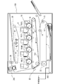
- FIG. 1 is a sectional view of an image forming apparatus according to an embodiment of the present invention.
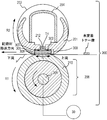
- FIG. 2 is a sectional view of the image heating apparatus according to the first embodiment of the present invention.
- FIG. 3 is an explanatory diagram of the temperature control according to the embodiment of the present invention.
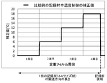
- FIG. 4 is an explanatory diagram of temperature control in a comparative example of the embodiment of the present invention.
- FIG. 5 is an explanatory diagram of the temperature control according to the first embodiment of the present invention.
- 6A to 6C are configuration diagrams of the heater according to the second embodiment of the present invention.
- FIG. 7 is a heater control circuit diagram according to the second embodiment of the present invention.
- FIG. 8 is an explanatory diagram of a heating region according to the second embodiment of the present invention.
- FIG. 9A and 9B are explanatory diagrams of the heating region according to the second embodiment of the present invention.
- FIG. 10 is a flowchart of the heater control according to the second embodiment of the present invention.
- FIG. 11 is an explanatory diagram of the temperature control according to the second embodiment of the present invention.
- FIG. 12 is an explanatory diagram of the temperature control according to the second embodiment of the present invention.
- FIG. 13 is an explanatory diagram of the temperature control according to the second embodiment of the present invention.
- FIG. 14 is an explanatory diagram of a heating region according to the second embodiment of the present invention.
- FIG. 15 is an explanatory diagram of the temperature control according to the second embodiment of the present invention.
- FIG. 16 is an explanatory diagram of a heating region according to the third embodiment of the present invention.
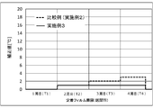
- FIG. 17 is a graph illustrating a comparative example of Example 3 of the present invention.
- FIG. 18 is an explanatory diagram of a comparative example of Example 3 of the present invention.
- FIG. 19 is an explanatory diagram of the temperature control according to the third embodiment of the present invention.
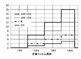
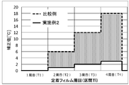
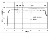
- FIG. 20 is a graph illustrating Example 3 of the present invention.
- FIG. 1 is a schematic sectional view of an image forming apparatus according to an embodiment of the present invention.
- an image forming apparatus to which the present invention can be applied there are a printer, a copying machine, a facsimile apparatus, and the like using an electrophotographic system or an electrostatic recording system.
- a case where the present invention is applied to a laser beam printer will be described.
- the image forming apparatus 100 receives a print signal, which is image information transmitted from an external device such as a personal computer, and forms a laser beam that forms an image on the recording material P using an electrophotographic method. It is a printer.
- the external device and the image forming apparatus 100 are connected via a control circuit 400 as a control unit in the image forming apparatus 100.
- image formation is performed by the following operation.
- the scanner unit 20 emits a laser beam modulated according to image information, and scans the surface of the photosensitive drum 19 charged to a predetermined polarity by the charging roller 16. As a result, an electrostatic latent image is formed on the photosensitive drum 19.
- toner developer
- the electrostatic latent image on the photosensitive drum 19 is developed as a toner image (developer image).
- the toner images of four colors are sequentially superimposed by being sequentially transferred onto the intermediate transfer body (intermediate transfer belt) 103 by the transfer electric field applied to the primary transfer roller 21, and the toner images of a plurality of colors are formed. Is formed on the intermediate transfer member 103.
- the toner image transferred onto the intermediate transfer member 103 is transferred onto the recording material P by a transfer electric field applied to the secondary transfer roller 22 at a secondary transfer portion formed by the intermediate transfer member 103 and the secondary transfer roller 22. The secondary transfer is performed.
- the recording material P is stacked and stored in the paper feed cassette 11.
- the recording material P is fed one by one from a paper feed cassette 11 by a pickup roller 12, passes through a pair of conveyance rollers 13 and a pair of registration rollers 14, and is synchronized with a toner image formed on the intermediate transfer body 103. Is conveyed toward the secondary transfer section.
- the recording material P on which the toner image has been transferred from the intermediate transfer body 103 in the secondary transfer portion is heated and pressed by a fixing device (image heating device) 200 as a fixing portion (image heating portion), and the toner image is transferred to the recording material.
- P is heated and fixed.
- the heating source of the fixing device 200 generates heat when electric power is supplied from the control circuit 400.
- the recording material P carrying the fixed toner image is discharged to a tray above the image forming apparatus 100 by the pair of conveying rollers 26.
- a cleaning unit including a photosensitive drum 19, a charging roller 16, and a drum cleaner 18, and a developing unit in which a developing roller 17 and toner are stored are integrated as a process cartridge 15, and are detachably mountable to the image forming apparatus 100. It is configured.
- the four process cartridges 15 are provided corresponding to the respective colors of cyan, magenta, yellow, and black, and have the same configuration except for the color of the toner to be stored.
- the above-described photosensitive drum 19, charging roller 16, scanner unit 20, developing roller 17, transfer rollers 21 and 22, and the like constitute an image forming unit that forms an unfixed toner image on the recording material P.
- the image forming apparatus 100 including the fixing device 200, the process cartridge 15, and the like are operated by a driving force obtained from a motor 30 as a driving source provided in the apparatus main body.
- the maximum sheet passing width in the direction orthogonal to the transport direction of the recording material P is 216 mm
- A4 size [210 mm ⁇ 297 mm] plain paper is transported at a transport speed of 230 mm / sec. It is possible to print sheets.
- FIG. 2 is a schematic cross-sectional view of the fixing device 200 of the present embodiment.
- the fixing device 200 includes a fixing film 202 as an endless belt, a pressing roller 208 as a pressing member that contacts an outer surface of the fixing film 202, and a metal stay 204.
- the pressure roller 208 forms a fixing nip N with the heater 300 via the fixing film 202.
- the fixing film 202 is a multi-layered, high heat-resistant fixing film 202 formed in a cylindrical shape, and has a base layer of a heat-resistant resin such as polyimide or a metal such as stainless steel.
- the surface of the fixing film 202 is formed as a release layer coated with a high-performance fluororesin having excellent releasability, such as PFA, which has excellent heat resistance and prevents adhesion of toner.
- a high heat-resistant rubber such as silicone rubber may be formed as an elastic layer between the base layer and the release layer.
- a fixing film 202 having an outer diameter of 24 mm having an elastic layer is used.
- the pressure roller 208 has a core 209 made of a material such as iron or aluminum, and an elastic layer 210 made of a highly heat-resistant rubber material such as silicone rubber. With such a configuration, by setting the pressure roller 208 to have appropriate hardness, a fixing nip N according to the specification of the fixing device 200 is obtained. In this embodiment, an elastic layer having a thickness of 4 mm and an outer diameter of 25 mm is used as the pressure roller 208.
- the heater 300 uses a ceramic-based heater. That is, the heater 300 includes the ceramic substrate 305 having high electrical insulation such as alumina, having excellent thermal conductivity, and low heat capacity. On the surface of the ceramic substrate 305 opposite to the side facing the fixing film 202, an electric heating resistor made of silver palladium or the like is arranged along the longitudinal direction of the substrate (the direction perpendicular to the drawing, the direction perpendicular to the recording material conveyance direction).
- the layer 302 (heating element) is formed by screen printing or the like. Further, a protective glass layer 307 of a thin layer of about 50 ⁇ m covers the current-carrying resistance layer 302 for the purpose of ensuring insulation of the current-carrying resistance layer 302.
- a ceramic substrate 305 having alumina (Al 2 O 3 ) as a base material was used.
- a sliding glass layer 308 having a thickness of about 10 ⁇ m is formed for the purpose of ensuring slidability with the fixing film 202.
- Fluorine-based grease (not shown) having excellent heat resistance is applied to the sliding glass layer 308 in order to enhance the slidability with the fixing film 202.
- the energization heating resistance layer 302 generates heat when AC voltage is supplied from electrodes (not shown) provided at both longitudinal ends of the heater 300, and the heater 300 includes a ceramic substrate 305, a protective glass layer 307, and a sliding glass layer 308. The whole heats up rapidly.
- the temperature rise of the heater 300 is detected by a thermistor TH (temperature detecting element) as a temperature detecting unit disposed on the back of the heater 300 and fed back to the control circuit 400.
- the control circuit 400 performs power control based on the phase and wave number of the AC voltage applied to the energized heating resistor layer 302 such that the temperature of the heater 300 detected by the thermistor TH is maintained at a predetermined control target temperature. )
- the control target temperature is maintained by control.
- a safety element 212 such as a thermoswitch or a temperature fuse that operates due to abnormal heat generation of the heater 300 and shuts off power supplied to the heater 300 directly or indirectly contacts the heater 300 via the heater holding member 201
- the heater 300 is held by a heater holding member 201 made of a heat-resistant resin, and heats the fixing film 202 by heating the inside of the fixing nip N.
- the heater holding member 201 also has a guide function for guiding the rotation of the fixing film 202.
- the metal stay 204 receives a pressing force (not shown) and presses the heater holding member 201 toward the pressing roller 208.
- the pressure roller 208 rotates in a direction indicated by an arrow R1 by receiving a rotational driving force from the motor 30. As the pressure roller 208 rotates, the fixing film 202 is driven to rotate in the direction of arrow R2.
- the heat from the heater 300 is applied through the fixing film 202 while nipping and transporting the recording material P in the fixing nip N, so that the unfixed toner image on the recording material P is fixed.
- Fixing Control The fixing control is executed as a fixing control by combining several controls. First, the basic control target temperature will be described.
- the basic control target temperature controls energization of the heater 300 so that the surface temperature of the fixing film 202 falls within a temperature range in which a fixing problem does not occur.
- the lower limit of the temperature range is equal to or higher than a temperature at which fixing failure (a phenomenon in which a toner image is not fixed as a permanent image on the recording material P) does not occur, and the upper limit is equal to or lower than a temperature at which high-temperature offset does not occur.
- the fixing device 200 of the film heating type using the thin fixing film 202 as a fixing member is constituted by a member having a reduced heat capacity in order to realize a quick start to shift to a state where fixing can be performed in an extremely short time. Since a member having a reduced heat capacity has a small heat storage capacity, the temperature of the member increases when continuous fixing is performed as a control target temperature of a constant temperature, and a high-temperature offset may occur. Therefore, stepwise temperature control is incorporated in which the control target temperature is lowered stepwise in accordance with the number of sheets on which the recording material P has been fixed, as shown in FIG.
- the reason why the correction value is set to 0 ° C. in the middle of the fourth rotation of the fixing film is at a timing when the A4-size recording material passes through the fixing nip, and is prepared for fixing the subsequent recording material P. This timing varies depending on the size of the recording material P to be passed.
- the control unit also incorporates a fixing device temperature rising state control corresponding to the temperature rising state of the fixing device 200 from the temperature detected by the thermistor T at the start of fixing.
- a fixing temperature rising state control as shown in Table 1, when the detected temperature is high, the fixing device 200 determines that the temperature is in the state of being raised and corrects the control target temperature to be low. If the detected temperature is low, it is determined that the fixing device 200 is in a cold state, and the control target temperature is corrected to be high.
- Table 1 shows correction values of the fixing unit temperature rising state control.
- the control target temperature is set according to the type of the recording material P.
- the type of the recording material P for example, a paper having a basis weight of 65 to 80 [g / m 2 ], a recording material P having a larger basis weight, gloss, Examples include paper, envelopes and label paper. Paper type control corresponding to various recording materials P in which control target temperatures for fixing these various recording materials P are respectively set is also incorporated.
- ⁇ Environmental correction control> There is also environmental correction control in which the temperature and humidity in the atmosphere where the image forming apparatus 100 is placed are detected by using environment detecting means such as a temperature / humidity sensor, and controlled at a control target temperature suitable for the environment.
- environment detecting means such as a temperature / humidity sensor
- a control target temperature suitable for the environment.
- the environment in which the image forming apparatus 100 is placed is a low-temperature environment, the temperatures of the recording material P and the toner also become low. In a high-temperature environment, the temperatures of the recording material P and the toner also increase. Therefore, by setting the control target temperature low, high-temperature offset and curl are prevented.
- Non-paper passing area temperature rise suppression control As a recording material P having a width smaller than the maximum width (LTR (width 216 mm) in this embodiment) that can be passed by the image forming apparatus 100, A5 (148 mm width) recording paper or Japanese Standard envelope "Long type No. 4" (width 90 mm) and the like.
- LTR width 216 mm
- A5 148 mm width
- Japanese Standard envelope "Long type No. 4" width 90 mm
- a thermistor is provided at the longitudinal end of the heater 300 to detect a rise in the temperature of the non-sheet passing portion.
- Non-sheet-passing part temperature rise suppression control for suppressing the non-sheet-passing part temperature rise is also realized.
- the correction in the recording material medium temperature control is such that the fixing property does not deteriorate toward the rear end of the recording material P even under the condition where the fixing property is most severe. It is the recording material P and the toner image carried on the recording material P that remove heat from the fixing film 202 and the pressure roller 208.
- the control for setting the heat amount suitable for the recording material P is performed by the paper type control, the effect of the toner image depends on the toner amount. If the amount of toner is small, the amount of heat removed is small, and if the amount of toner is large, the amount of heat removed is large. In the color image forming apparatus used in the present embodiment, the amount of heat taken by the “entire secondary color” in which the secondary color red, blue, or green image is on the entire surface is greatest, and Is an image in which the fixability of the image becomes severe.
- Table 2 shows the results of verifying the curl when the image pattern is changed using the image forming apparatus 100 that performs the correction of +6 [° C.] for each rotation of the fixing film as the conventional control of the temperature in the recording material. Verification was performed under the following conditions. The environment was performed under an environment of 27 ° C./65% assuming a normal office environment. The recording material P was printed on only one side using a sheet of PB PAPER having a small basis weight, 64 [g / m 2 ] (manufactured by Canon Inc.), which was easily curled and left for one week.
- the fixing device 200 In order to pass the paper, the fixing device 200 is cooled down to room temperature to 10 sheets continuously in order to make the conditions uniform, and the discharged recording material P is placed on a flat plate, and the curl amount of four squares (the square raised from the flat plate) is set. From the flat plate) was measured. Numerical values in the table are curl amounts curving toward the side opposite to the printing surface. The average value is the average value of a total of 40 data of 10 squares, and the maximum value is the maximum value of the 40 data.
- the image patterns were four types of images: red secondary colors having the highest fixability, black primary colors, those having characters in the table, and only characters.
- the curl amount is small in the optimized overall secondary color.
- the amount of heat taken by the toner image is small, the amount of heat applied to the recording material P is large, and the curl amount is large.
- the temperature control in the recording material is changed according to the toner image information printed on the recording material P, and the effect is to minimize the curl.
- the maximum toner amount and the toner occupancy are used as the toner image information.
- the maximum toner amount is the maximum value of the toner amount in the minimum pixel (unit pixel) and is calculated according to the following flow.
- Image data transmitted from an external device such as a host computer to the image forming apparatus 100 is converted into bitmap data by a control circuit 400 having a function of obtaining a toner image as an obtaining unit.
- the number of pixels of the image forming apparatus 100 of this embodiment is 600 dpi, and the control circuit 400 creates bitmap data (image density data of each of CMYK colors) according to the transmitted image data.
- Image data of each color of CMYK is obtained for each pixel from the created bitmap data, and d (C), d (M), d (Y), d (K) are obtained as image data of each color of CMYK for each pixel. , D (CMYK), which is the sum of these values, is calculated for each pixel. Such calculation is performed for the pixels of the entire recording material P.
- the image signal of the control circuit 400 is 8 bits, and the image data of each color is expressed in a range from 00 hex which is the minimum density to FF hex which is the maximum density.
- An image having a maximum toner amount exceeding 100% has a large image density on the recording material P and a large amount of toner. Therefore, the amount of heat required to melt and fix the toner also increases, and the control target temperature is increased. Become. Conventionally, it is set as a control target temperature at which a reliable fixing property can be obtained even with an image having such a maximum toner amount.
- the correction value by the recording medium temperature control of the present embodiment is set as shown in Table 3 according to the thus calculated maximum toner amount and toner image information of the toner occupancy.
- Table 3 The control is suitable for the image.
- the effects of this embodiment will be described. The effect was verified under the same conditions as the curl verification in the comparative example.
- the maximum toner amount and the toner occupancy of the image pattern used for the curl verification in the comparative example are: maximum toner amount: 200 [%] / toner occupancy: 100 [%] for the entire secondary color. Similarly, the maximum toner amount: 100 [%] / toner occupancy: 100 [%] for the entire primary color, the maximum toner amount: 100 [%] / toner occupancy: 16 [%] in the table, and the maximum toner amount for characters : 100 [%] / toner occupancy: 4 [%].
- the correction value for the entire secondary color is the same as that of the related art.
- the correction value is reduced. That is, the correction amount (the amount of increase in the control target temperature) that is cumulatively added from the region on the front end side to the region on the rear end side of the recording material depends on the type and content of the unfixed toner image formed on the recording material. Is set. As described above, the amount of heat applied to the recording material P is optimized by changing the correction value of the temperature control in the recording material according to the toner image.
- the recording medium temperature control is corrected for each rotation of the fixing film 202.
- the following development is also possible. Conceivable. For example, when the toner image disappears at the trailing end of the recording material P, no correction is performed. When the toner image changes in the middle of the recording material P, correction is performed according to the changed toner image information. It is also possible to control the inside temperature of the recording material by combining them, and a selection is made as needed.
- the curl amount can be minimized irrespective of the image pattern by controlling the temperature in the recording material suitable for the toner image to be printed, and curling does not become a problem.
- the fixing device 200 can be realized.
- In the present embodiment has a section obtained by dividing the interval T i based on the circumferential length of the fixing film 202 may be based on the circumference of the pressure roller 208.
- Example 2 Second Embodiment A fixing device according to a second embodiment of the present invention will be described.
- the second embodiment relates to a fixing device 200b employing a divided heater having a plurality of heating elements as an application example of the first embodiment.
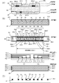
- the configuration of the divided heater 300b according to the present embodiment will be described with reference to FIGS. 6A to 6C.
- Configuration of heater 300b (common to split heaters) 6A is a cross-sectional view of the heater 300b
- FIG. 6B is a plan view of each layer of the heater 300b
- FIG. 6C is a diagram illustrating a method of connecting the electric contact C to the heater 300b.
- FIG. 6B illustrates the transport reference position X of the recording material P in the image forming apparatus 100 according to the present exemplary embodiment.
- the conveyance reference is the center reference
- the recording material P is conveyed so that the center line in the direction orthogonal to the conveyance direction is along the conveyance reference position X.
- FIG. 6A is a cross-sectional view of the heater 300b at the transport reference position X.
- the heater 300b is provided on a substrate 305 made of ceramics, a back surface layer 1 provided on the substrate 305, a back surface layer 2 covering the back surface layer 1, and a surface of the substrate 305 opposite to the back surface layer 1. It comprises a sliding surface layer 1 and a sliding surface layer 2 covering the sliding surface layer 1.
- the back layer 1 has the conductor 301 (301a, 301b) provided along the longitudinal direction of the heater 300b.
- the conductor 301 is separated into a conductor 301a and a conductor 301b, and the conductor 301b is disposed downstream of the conductor 301a in the transport direction of the recording material P.
- the back surface layer 1 has conductors 303 (303-1 to 303-7) provided in parallel with the conductors 301a and 301b.
- the conductor 303 is provided between the conductor 301a and the conductor 301b along the longitudinal direction of the heater 300b.
- the back layer 1 has a heating element 302a (302a-1 to 302a-7) and a heating element 302b (302b-1 to 302b-7).
- the heating element 302a is provided between the conductor 301a and the conductor 303, and generates heat by supplying power through the conductor 301a and the conductor 303.
- the heating element 302b is provided between the conductor 301b and the conductor 303, and generates heat by supplying power through the conductor 301b and the conductor 303.
- the heat generating portion including the conductor 301, the conductor 303, the heat generator 302a, and the heat generator 302b is divided into seven heat blocks (HB 1 to HB 7 ) in the longitudinal direction of the heater 300b. That is, the heating element 302a is divided into seven areas of the heating elements 302a-1 to 302a-7 in the longitudinal direction of the heater 300b. The heating element 302b is divided into seven areas of heating elements 302b-1 to 302b-7 in the longitudinal direction of the heater 300b. Further, the conductor 303 is divided into seven regions of the conductors 303-1 to 303-7 according to the division positions of the heating elements 302a and 302b.
- Heating range of this embodiment is in the range from left end in the drawing of the heating blocks HB 1 to right end in the drawing of the heating block HB 7, its length is 220 mm. Further, the length in the longitudinal direction of each heat generating block is all the same 31.4 mm, but the lengths may be different.
- the back surface layer 1 has electrodes E (E 1 to E 7 , and E 8-1 and E 8-2 ).
- the electrodes E 1 to E 7 are provided in the regions of the conductors 303-1 to 303-7, respectively, and supply power to the heating blocks HB 1 to HB 7 via the conductors 303-1 to 303-7, respectively.
- Electrode for The electrodes E 8-1 and E 8-2 are provided at the longitudinal ends of the heater 300b so as to be connected to the conductor 301, and supply power to the heat generating blocks HB 1 to HB 7 via the conductor 301. Electrode. In this embodiment, the electrodes E 8-1 and E 8-2 are provided at both ends in the longitudinal direction of the heater 300b.
- a configuration in which only the electrode E 8-1 is provided on one side may be used.
- power is supplied to the conductors 301a and 301b by a common electrode, individual electrodes may be provided for each of the conductors 301a and 301b to supply power.
- the back surface layer 2 is made up of a surface protection layer 307 having an insulating property (glass in this embodiment), and covers the conductor 301, the conductor 303, and the heating elements 302a and 302b.
- the surface protection layer 307 is formed except for the location of the electrode E, and has a configuration in which the electrical contact C can be connected to the electrode E from the back layer 2 side of the heater 300b.
- the sliding surface layer 1 is provided on the surface of the substrate 305 opposite to the surface on which the back surface layer 1 is provided, and the thermistors TH (TH1-1 to TH1) for detecting the temperatures of the heat generating blocks HB1 to HB7. -4, and TH2-5 to TH2-7).
- the thermistor TH is made of a material having PTC characteristics or NTC characteristics (NTC characteristics in this embodiment), and has a configuration in which the temperatures of all the heat generating blocks can be detected by detecting the resistance values.
- the sliding surface layer 1 is provided with a conductor ET (ET1-1 to ET1-4 and ET2-5 to ET2-7) and a conductor EG (EG1, EG2).
- the conductors ET1-1 to ET1-4 are connected to thermistors TH1-1 to TH1-4, respectively.
- the conductors ET2-5 to ET2-7 are connected to thermistors TH2-5 to TH2-7, respectively.
- the conductor EG1 is connected to the four thermistors TH1-1 to TH1-4 and forms a common conductive path.
- the conductor EG2 is connected to the three thermistors TH2-5 to TH2-7 and forms a common conductive path.
- the conductor ET and the conductor EG are each formed along the length of the heater 300b up to the longitudinal end, and are connected to the control circuit 400 via electrical contacts (not shown) at the heater 300b longitudinal end.
- the sliding surface layer 2 is composed of a surface protective layer 308 having a sliding property and an insulating property (in the present embodiment, glass).
- the sliding face layer 2 covers the thermistor TH, the conductor ET, and the conductor EG. And slidability.
- the surface protection layer 308 is formed except for both longitudinal ends of the heater 300b in order to provide an electrical contact with the conductor ET and the conductor EG. Subsequently, a method of connecting the electric contact C to each electrode E will be described.
- FIG. 3C is a plan view showing a state where the electric contacts C are connected to the respective electrodes E, as viewed from the heater holding member 201 side.
- through holes are provided at positions corresponding to the electrodes E (E 1 to E 7 , and E 8-1 and E 8-2 ).
- the electrical contacts C (C 1 -C 7 , and C 8-1 , C 8-2 ) are connected to the electrodes E (E 1 -E 7 , and E 8-1 , E 8-2 ).
- they are electrically connected by a method such as urging by a spring or welding.
- the electric contact C is connected to a control circuit 400 of the heater 300b described later via a conductive material (not shown) provided between the metal stay 204 and the heater holding member 201.
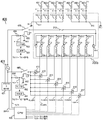
- FIG. 7 is a circuit diagram of the control circuit 400 of the heater 300b according to the first embodiment.
- a commercial AC power supply 401 is connected to the image forming apparatus 100.
- the power control of the heater 300b is performed by turning on / off the triacs 411 to 417.
- the triacs 411 to 417 operate according to FUSER1 to FUSER7 signals from the CPU 420, respectively.
- the drive circuits of the triacs 411 to 417 are not shown.
- the control circuit 400 of the heater 300b has a circuit configuration capable of independently controlling the seven heating blocks HB 1 to HB 7 by the seven triacs 411 to 417.
- the zero-cross detector 421 is a circuit that detects a zero-cross of a commercial AC power supply that operates the image forming apparatus 100, and outputs a zero-cross signal to the CPU 420.
- the zero cross signal is used for phase control of the triacs 411 to 417, detection of wave number control timing, and the like.
- the temperature detection of the heater 300b is performed by thermistors TH (TH1-1 to TH1-4, TH2-5 to TH2-7).
- the partial pressure of the thermistors TH1-1 to TH1-4 and the resistors 451 to 454 is detected as signals TH1-1 to TH1-4 by the CPU 420, and the CPU 420 converts the signals TH1-1 to TH1-4 to temperatures. Converting.
- the voltage division between the thermistors TH2-5 to TH2-7 and the resistors 465 to 467 is detected by the CPU 420 as signals TH2-5 to TH2-7, and the CPU 420 outputs the signals TH2-5 to TH2-7. Converting signal to temperature.
- the power to be supplied is calculated by, for example, PI control (proportional-integral control) based on the control target temperature TGTi of each heat generating block described later and the temperature detected by the thermistor TH. Further, the supplied power is converted into a phase angle (phase control) or a wave number (wave number control) control level corresponding to the power, and the triacs 411 to 417 are controlled based on the control conditions.
- the CPU 420 serves as a control unit and an acquisition unit according to the present invention, and executes various calculations and energization control related to the temperature control of the heater 300.
- the relay 430 and the relay 440 ensure safety by using the relay 300 and the relay 440 as a power cutoff unit for the heater 300b when the temperature of the heater 300b excessively rises due to a failure or the like.
- the relay 430 is turned off to ensure safety.
- the relay 440 is turned off to secure safety.
- the transistor 433 When the RLON signal goes high, the transistor 433 goes on, power is supplied to the secondary coil of the relay 430 from the power supply voltage Vcc, and the primary contact of the relay 430 goes on.
- the transistor 433 When the RLON signal goes low, the transistor 433 is turned off, the current flowing from the power supply voltage Vcc to the secondary coil of the relay 430 is cut off, and the primary contact of the relay 430 is turned off.
- the transistor 443 when the RLON signal goes high, the transistor 443 turns on, power is supplied to the secondary coil of the relay 440 from the power supply voltage Vcc, and the primary contact of the relay 440 turns on.
- the transistor 443 When the RLON signal goes low, the transistor 443 is turned off, the current flowing from the power supply voltage Vcc to the secondary coil of the relay 440 is cut off, and the primary contact of the relay 440 is turned off.
- the resistors 434 and 444 are current limiting resistors.
- the comparison unit 431 operates the latch unit 432, and the latch unit 432 latches the RLOFF1 signal in a low state. I do.
- the RLOFF1 signal goes low, the transistor 433 is kept off even when the CPU 420 puts the RLON signal high, so that the relay 430 can be kept off (safe state).
- the latch unit 432 outputs the RLOFF1 signal in the open state in the non-latched state.
- the comparison unit 441 operates the latch unit 442, and the latch unit 442 outputs the RLOFF2 signal to Low. Latch in state.
- the RLOFF2 signal goes low, the transistor 443 is kept off even if the CPU 420 puts the RLON signal high, so that the relay 440 can be kept off (safe state).
- the latch unit 442 outputs the RLOFF2 signal in the open state in the non-latched state.
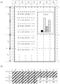
- Heating Area FIG. 8 is a diagram showing the relationship between the heating blocks of the heater 300b and the heating areas A 1 to A 7 in the present embodiment, and is shown in comparison with an A4-size recording material.
- the recording material P passes through the fixing nip N and segmentation at a predetermined time Tn, and performs the recording material in a temperature-controlled by the heating areas A i.
- the sectioning is performed for each rotation of the fixing film (75.4 mm), which is a feature of the present embodiment.
- the first section is based on the leading edge of the recording material P, the section T 1 , the second section is the section T 2 , and the third section. Is defined as a section T 3 ,.
- a recording material width end Direction end portions perpendicular to the conveying direction of the recording material P (hereinafter, referred to as a recording material width end) of a size that passes through A 7 from the heating region A 1, if the image is present in the position shown in FIG. 9A classification of the heating area a i is as shown in the table of FIG. 9B.
- the sections T 1 to T 2 are classified as image heating areas AI (Image of Area), since any of the heating areas A 1 to A 7 pass through the image range.
- the heating areas A 1 to A 4 are classified as image heating areas AI, and the heating areas A 5 to A 7 are classified as non-image heating areas AP (Paper of Area) because the image range does not pass through. Is done.
- the size of the recording material P shown in FIG. 9A is A4, and the recording material P passes through all the heating regions Ai.
- the width of the recording material P is narrow, and for example, the heating regions A 1 and A 7 are formed by the recording material P. If P does not pass, it is classified as a non-paper passing heating area AN (Non Paper of Area).
- Heating value of the heating block HB i is determined by the electric power supplied to the heating blocks HB i.
- the amount of heat generation of the heating block HB i is increased, by reducing the power supplied to the heating blocks HB i, the amount of heat generation of the heating block HB i decreases.
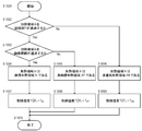
- the control target temperature TGT i of each heating block is set according to the classification of the heating area A i determined by the flowchart of FIG.
- Classification of the heating area A i includes an image data sent from an external device such as a host computer (not shown) (image information) is performed based on the size information of the recording material P. That determines the passage of the recording material P of the heating area A i (S1002), if not pass classifies the heating area A i in the non-paper passing heated area AN (S1006). If the heating area A i is the recording material P passes through the image area heating region A i to determine whether to pass (S1003). When passing through the classification heating area A i and the image heating area AI (S1004), if not pass classifies the heating area A i and the non-image heating area AP (S1005).
- the heating area A i is explained when it is classified as an image heating area AI (S1004).
- T AI is an image heating area reference temperature, which is set as an appropriate temperature for fixing the unfixed toner image on the recording material P.
- the image heating area reference temperature T AI 220 ° C. It is desirable that the image heating area reference temperature T AI be a temperature corrected by the paper type control described in the first embodiment.
- the correction value is set to 0 for the entire secondary color having severe fixability, and the image heating area reference temperature TAI is corrected to be lower as the maximum toner amount decreases.
- T AP is a non-image heating region reference temperature, by setting a temperature lower than the image heating reference temperature T AI, lowering the heating value of the heating block HB i in the non-image heating area AP than the image heating area AI Therefore, power saving of the image forming apparatus 100 is achieved.
- the non-image heating area reference temperature TAP is lowered too much, the maximum power that can be applied to the heat generating block HB i is applied when the heating area A i switches from the non-image heating area AP to the image heating area AI.
- the temperature cannot be increased to the control target temperature TAP of the image section.
- a fixing failure which is a phenomenon that the toner image cannot be reliably fixed to the recording material P
- Such control heating area A 5 ⁇ 7 will be controlled by the image heating reference temperature T AI as the control target temperature as a section T 1 ⁇ T 2 In the image heating area AI. Also, it will be controlled by the non-image heating reference temperature T AP as the control target temperature of the non-image heating area AP in the section T 3 ⁇ T 4.
- T AN is a non-sheet-passing the heating region reference temperature, by setting a temperature lower than the non-image heating reference temperature T AP, than the non-image heating area AP of the heating value of the heating block HB i in the non-paper passing heated area AN In order to reduce the power consumption of the fixing device 200b.
- the non-sheet-passing heating area reference temperature TN is too low, the sliding property between the inner surface of the fixing film 202 and the heater 300b deteriorates, and the conveyance of the recording material P becomes unstable.
- the non-paper passing the heating region reference temperature T AN is to be determined in consideration of the configuration of the fixing device 200b including the viscosity properties of the grease, is not limited to 128 ° C..
- Second Embodiment Temperature Control in Recording Material Temperature control in a recording material according to the second embodiment will be described.
- the conventional medium temperature control of the recording material is performed in the same manner as in the first embodiment so that even if a secondary color image having the maximum toner amount is formed on the entire surface, the fixing property toward the rear end of the recording material P is ensured.
- Control is performed with the correction values shown in FIG.
- the correction value of the temperature control in the recording material is optimized in accordance with the toner image information of each heating area, and the heating element is divided into a plurality of parts. It is possible to control the temperature in the recording material in accordance with the image.
- the maximum toner amount and the toner occupancy are used as the toner image information as in the first embodiment.
- the control target temperature of the image shown in FIG. 9A will be described.
- the correction is performed at + 6 ° C. in the comparative example because the correction is not based on the toner image information.
- the correction value suitable for the toner occupation ratio of 4% is + 1 ° C. according to Table 3. Is corrected by
- FIG. 11 shows control target temperatures of the heating areas A 1 to A 4 in the comparative example and the embodiment 2 by the control of the temperature in the recording material.
- the control target temperature of the heating areas A 1 to A 4 is smaller than that of the comparative example by controlling the medium temperature of the recording material according to the amount of toner, and the control target temperature is kept low. Calorific value can be reduced.
- the curl can be reduced by controlling the medium temperature in the recording material in Example 2, and that the difference between the left and right curls can be reduced.
- the difference between left and right curls will be described.
- the heat amounts of the heating areas A 5 to A 7 are suitable for the toner amount
- the heat amounts of the heating areas A 1 to A 4 are excessive with respect to the toner amount.
- the curl generated on the left side is large, and the curl has a left-right difference.
- the second embodiment is characterized in that the control target temperature of the heating areas A 1 to A 4 where the toner amount is small can be lowered, so that the amount of heat applied to the recording material P can be equalized right and left. Left and right differences can be eliminated.
- the fixing member and the pressing member do not receive an excessive amount of heat, and the heat deterioration of the member can be reduced, thereby stabilizing the image heating apparatus through durability. It also enhances the character.
- the correction value of the temperature control in the recording material in the heating areas A 5 to A 7 is set to +6 [° C.] suitable for the maximum toner amount in the sections T 1 to T 2 , and the correction in the sections T 3 to T 4 is also performed.
- the correction in the sections T 3 to T 4 where there is no toner image is performed by the correction value of the temperature control in the recording material suitable for the absence of the toner image (that is, the maximum toner amount and the toner occupation in the area corresponding to the sections T 3 to T 4).
- the rate is set to +1 [° C.] according to Table 3 assuming 0%.
- FIG. 12 shows the transition of the control target temperature in the first application example of the second embodiment.
- FIG. 13 shows a transition of the control target temperature in the application mode 2 of the second embodiment.
- the control target temperature of the section T 4 which no toner image section followed, in preparation for fixing the subsequent recording material P which in an image heating reference temperature T AI 222 [°C] It is.
- FIG. 13 shows a transition of the control target temperature in the application mode 3 of the second embodiment.
- there has been a change from the period T 4 it is also conceivable to return from the interval T 3 to which the toner image is eliminated.
- the temperature control in the recording material in the sections T 1 to T 2 of the heating areas A 5 to A 7 without the toner image is corrected by +1 [° C.] according to Table 3 (that is, the section T 1).
- maximum toner amount and toner occupancy in a region corresponding to ⁇ T 2 is set to both 0%).
- the correction of + 6 ° C. that is, the maximum toner amount in the area corresponding to the sections T 3 to T 4 is 200%, and the toner occupancy is about 23%).
- Application forms of a development of the applied mode 4 5 is for performing a correction from the interval T 2 as a recording material in the temperature control with the fixing of the section T 3 with the toner image.
- the correction is +3 [° C.] as compared with the application mode 4.
- the correction value of the recording material in the temperature control comprises a section T i that has toner image It is desirable to set a value suitable for the fixing device 200b and the image forming apparatus 100.
- the control based on the toner amount the recording medium temperature control using the maximum toner amount and the toner occupancy is used.
- the present invention is not limited to this.
- the object can also be achieved by performing control using the toner image information.
- the energization to the heating areas divided according to the image to be printed by the user is independently controlled.
- the curl can be suppressed.
- Example 3 Third Embodiment A third embodiment of the present invention will be described.
- the temperature control in the recording material is changed according to the toner image information of the heating area adjacent to the divided heater.
- the heating areas A 1 to A 5 are image heating areas having a toner image
- the heating areas A 6 to A 7 are non-image heating areas having no toner image. If a large number print such images in succession, since the heating region A 6 ⁇ A 7 is no toner image to take the heat, even when the correction by the recording material in the temperature control in Embodiment 2, the heating region A 6 it was found that the surface temperature of the fixing film 202, which corresponds to ⁇ a 7 resulting in temperature increase. Therefore, the surface temperature of the fixing film 202 corresponding to the heating areas A 6 to A 7 after a large number of continuous paper passes becomes higher than the portion corresponding to the heating areas A 1 to A 5.
- heating region A 7 becomes high. This is heating area A 5 which is adjacent to the heating area A 6 has a toner image, by heat from the heating region A 6 flows into the heating area A 5, the surface of the fixing film 202 corresponding to the heating area A 6 The temperature rise is smaller. On the other hand, the neighboring heating region A heated region A 7 is not a toner image to 6 without heat is taken away, Atsushi Nobori of the surface temperature of the fixing film 202 corresponding to the heating area A 7 is increased.
- the surface temperature of the fixing film 202 is increased by setting the correction value of the temperature control in the recording material in the heating areas A 6 to A 7 serving as the non-image image heating area to 0.
- the temperature is controlled, and the recording medium temperature control is performed as shown in FIG.
- the correction value in the section T 3 to T 4 on the rear end side of the recording material is set to zero.
- the timing at which the correction value is set to zero may be appropriately set according to the apparatus configuration. It is possible and is not limited to such a configuration.
- the correction value of the period T 4 may be zero.
- Example 2 was used as a comparative example. Table 7 shows the results of the verification.
- Example 2 As shown in Table 7, even in Example 2 as a comparative example, it was found that high-temperature offset did not occur for up to 25 continuous paper passes, but occurred for 30 sheets. On the other hand, in the present example, it was confirmed that high-temperature offset did not occur even when 80 sheets were continuously printed.
- FIG. 20 shows the results of measuring the surface temperature of the fixing film 202 at a portion corresponding to the heating area A7 in the comparative example and the present example.
- the image heating apparatus according to the present embodiment can suppress the temperature increase of the surface temperature of the fixing film 202. I can confirm that I can do it.
- the heating area A 5 which is an image heating region adjacent to the heating area A 6 has a toner image, by heat from the heating region A 6 flows into the heating area A 5, the fixing film 202 corresponding to the heating area A 6 Temperature rise is small.
- the heating area A 7 adjacent to the heating area A 6 which is a non-image heating area, is not deprived of heat, and the surface temperature of the fixing film 202 corresponding to the heating area A 7 rises greatly.
- the correction value is set to minus. By doing so, the surface temperature of the fixing film 202 can be made uniform.
- the temperature control in the recording material is set to a correction value 0 without correction, and the non-image heating area adjacent to the non-image heating area A 6 is set to 0.
- recording medium in the temperature control of a 7 is a -1 [° C.] recording medium in the temperature control of the negative correction.
- Correction value of the recording material in the temperature control in the absence heating area A i of the toner image described in the present embodiment is a matter of choice depending on the fixing device 200b or the image forming apparatus 100 to be used.
- a configuration is also conceivable in which a means for detecting a rise in the surface temperature of the fixing film 202 is provided, and the correction value of the in-recording material temperature control is changed according to the detected temperature.
- the correction of the temperature control in the recording material is changed according to the information of the adjacent toner images, thereby making the surface temperature of the fixing film 202 uniform. And succeeded in stabilizing the image quality of the succeeding paper.
- 201 heater holding member
- 202 fixing film
- 204 metal stay
- 208 pressure roller
- 212 safety element
- 300 heater
- 400 control circuit
- N fixing nip
- P recording material
- TH thermistor
Landscapes
- Physics & Mathematics (AREA)
- General Physics & Mathematics (AREA)
- Fixing For Electrophotography (AREA)
- Control Or Security For Electrophotography (AREA)
Priority Applications (5)
| Application Number | Priority Date | Filing Date | Title |
|---|---|---|---|
| CN201980046927.XA CN112424701B (zh) | 2018-07-18 | 2019-07-12 | 图像加热装置和图像形成装置 |
| KR1020217003815A KR102575264B1 (ko) | 2018-07-18 | 2019-07-12 | 상 가열 장치 및 화상 형성 장치 |
| EP19837330.0A EP3825774B1 (en) | 2018-07-18 | 2019-07-12 | Image heating device and image formation device |
| US17/150,621 US11320768B2 (en) | 2018-07-18 | 2021-01-15 | Image heating apparatus and image formation apparatus with power supply control that sets a target temperature for each of a plurality of regions of recording material |
| US17/699,639 US11809104B2 (en) | 2018-07-18 | 2022-03-21 | Image heating apparatus and image formation apparatus with power supply control that sets a target temperature for each of a plurality of regions of recording material |
Applications Claiming Priority (2)
| Application Number | Priority Date | Filing Date | Title |
|---|---|---|---|
| JP2018-134919 | 2018-07-18 | ||
| JP2018134919A JP7073217B2 (ja) | 2018-07-18 | 2018-07-18 | 像加熱装置及び画像形成装置 |
Related Child Applications (1)
| Application Number | Title | Priority Date | Filing Date |
|---|---|---|---|
| US17/150,621 Continuation US11320768B2 (en) | 2018-07-18 | 2021-01-15 | Image heating apparatus and image formation apparatus with power supply control that sets a target temperature for each of a plurality of regions of recording material |
Publications (1)
| Publication Number | Publication Date |
|---|---|
| WO2020017452A1 true WO2020017452A1 (ja) | 2020-01-23 |
Family
ID=69164453
Family Applications (1)
| Application Number | Title | Priority Date | Filing Date |
|---|---|---|---|
| PCT/JP2019/027691 Ceased WO2020017452A1 (ja) | 2018-07-18 | 2019-07-12 | 像加熱装置及び画像形成装置 |
Country Status (6)
| Country | Link |
|---|---|
| US (2) | US11320768B2 (enExample) |
| EP (1) | EP3825774B1 (enExample) |
| JP (1) | JP7073217B2 (enExample) |
| KR (1) | KR102575264B1 (enExample) |
| CN (1) | CN112424701B (enExample) |
| WO (1) | WO2020017452A1 (enExample) |
Families Citing this family (6)
| Publication number | Priority date | Publication date | Assignee | Title |
|---|---|---|---|---|
| JP7073217B2 (ja) * | 2018-07-18 | 2022-05-23 | キヤノン株式会社 | 像加熱装置及び画像形成装置 |
| JP7541877B2 (ja) | 2020-08-31 | 2024-08-29 | キヤノン株式会社 | 画像形成装置およびその制御方法 |
| KR20250038748A (ko) | 2022-07-18 | 2025-03-19 | 뉴마 레스퍼러토리 인코포레이티드 | 작은 스텝 크기 및 고해상도 에어로졸 생성 시스템 및 방법 |
| US12092976B2 (en) | 2023-01-25 | 2024-09-17 | Toshiba Tec Kabushiki Kaisha | Fixing device and image forming apparatus with temperature sensor and controller |
| US12130570B2 (en) | 2023-02-24 | 2024-10-29 | Toshiba Tec Kabushiki Kaisha | Fixing device and image forming apparatus |
| CN118818937A (zh) * | 2023-04-19 | 2024-10-22 | 珠海奔图电子有限公司 | 一种定影温度控制方法 |
Citations (8)
| Publication number | Priority date | Publication date | Assignee | Title |
|---|---|---|---|---|
| JPS63313182A (ja) | 1987-06-16 | 1988-12-21 | Canon Inc | 像加熱装置 |
| JPH0695540A (ja) | 1992-09-11 | 1994-04-08 | Canon Inc | 加熱装置及び画像形成装置 |
| US20020067935A1 (en) * | 2000-12-01 | 2002-06-06 | Mcintyre C. Kevin | Method and system of fusing portions of a print medium |
| JP2007206327A (ja) * | 2006-02-01 | 2007-08-16 | Canon Inc | 加熱装置、加熱装置の制御方法及び画像形成装置 |
| JP2015034952A (ja) * | 2013-08-09 | 2015-02-19 | 富士ゼロックス株式会社 | 画像形成装置 |
| JP2016048402A (ja) * | 2016-01-08 | 2016-04-07 | キヤノン株式会社 | 画像形成装置 |
| JP2018004945A (ja) * | 2016-07-01 | 2018-01-11 | キヤノン株式会社 | 画像形成装置及び像加熱装置 |
| JP2018134919A (ja) | 2017-02-20 | 2018-08-30 | テイ・エス テック株式会社 | 車両用シート |
Family Cites Families (15)
| Publication number | Priority date | Publication date | Assignee | Title |
|---|---|---|---|---|
| JP3513283B2 (ja) | 1995-09-28 | 2004-03-31 | キヤノン株式会社 | 画像形成装置 |
| JP2001100588A (ja) | 1999-09-28 | 2001-04-13 | Canon Inc | 加熱装置および画像形成装置 |
| JP2008003326A (ja) * | 2006-06-22 | 2008-01-10 | Sharp Corp | 定着装置およびそれを備えてなる画像形成装置 |
| US8295752B2 (en) * | 2009-02-25 | 2012-10-23 | Fuji Xerox Co., Ltd. | Fixing device and image forming apparatus |
| CN103826335B (zh) * | 2009-09-11 | 2016-01-13 | 佳能株式会社 | 加热器和包括该加热器的图像加热装置 |
| JP5861446B2 (ja) * | 2011-12-21 | 2016-02-16 | 富士ゼロックス株式会社 | 定着装置及び画像形成装置 |
| JP2014077873A (ja) * | 2012-10-10 | 2014-05-01 | Ricoh Co Ltd | 定着装置の温度制御方法及び定着装置並びに画像形成装置 |
| JP5772852B2 (ja) * | 2013-03-22 | 2015-09-02 | コニカミノルタ株式会社 | 画像形成装置 |
| JP6202381B2 (ja) * | 2013-08-13 | 2017-09-27 | 株式会社リコー | 定着装置及び画像形成装置 |
| JP6661311B2 (ja) * | 2015-09-11 | 2020-03-11 | キヤノン株式会社 | 像加熱装置及び像加熱装置に用いるヒータ |
| JP6723845B2 (ja) | 2016-07-01 | 2020-07-15 | キヤノン株式会社 | 像加熱装置及び画像形成装置 |
| JP7073220B2 (ja) * | 2017-08-04 | 2022-05-23 | キヤノン株式会社 | 像加熱装置及び画像形成装置 |
| US10520864B2 (en) | 2017-10-04 | 2019-12-31 | Canon Kabushiki Kaisha | Image forming apparatus that controls a target temperature of a heating member based on whether pixels for forming an image are a predetermined density or more |
| JP7073217B2 (ja) * | 2018-07-18 | 2022-05-23 | キヤノン株式会社 | 像加熱装置及び画像形成装置 |
| JP7433956B2 (ja) * | 2020-02-12 | 2024-02-20 | キヤノン株式会社 | 定着装置、及びそれを用いた画像形成装置 |
-
2018
- 2018-07-18 JP JP2018134919A patent/JP7073217B2/ja active Active
-
2019
- 2019-07-12 EP EP19837330.0A patent/EP3825774B1/en active Active
- 2019-07-12 CN CN201980046927.XA patent/CN112424701B/zh active Active
- 2019-07-12 KR KR1020217003815A patent/KR102575264B1/ko active Active
- 2019-07-12 WO PCT/JP2019/027691 patent/WO2020017452A1/ja not_active Ceased
-
2021
- 2021-01-15 US US17/150,621 patent/US11320768B2/en active Active
-
2022
- 2022-03-21 US US17/699,639 patent/US11809104B2/en active Active
Patent Citations (9)
| Publication number | Priority date | Publication date | Assignee | Title |
|---|---|---|---|---|
| JPS63313182A (ja) | 1987-06-16 | 1988-12-21 | Canon Inc | 像加熱装置 |
| JPH0695540A (ja) | 1992-09-11 | 1994-04-08 | Canon Inc | 加熱装置及び画像形成装置 |
| US20020067935A1 (en) * | 2000-12-01 | 2002-06-06 | Mcintyre C. Kevin | Method and system of fusing portions of a print medium |
| JP2007206327A (ja) * | 2006-02-01 | 2007-08-16 | Canon Inc | 加熱装置、加熱装置の制御方法及び画像形成装置 |
| JP4757046B2 (ja) | 2006-02-01 | 2011-08-24 | キヤノン株式会社 | 定着装置 |
| JP2015034952A (ja) * | 2013-08-09 | 2015-02-19 | 富士ゼロックス株式会社 | 画像形成装置 |
| JP2016048402A (ja) * | 2016-01-08 | 2016-04-07 | キヤノン株式会社 | 画像形成装置 |
| JP2018004945A (ja) * | 2016-07-01 | 2018-01-11 | キヤノン株式会社 | 画像形成装置及び像加熱装置 |
| JP2018134919A (ja) | 2017-02-20 | 2018-08-30 | テイ・エス テック株式会社 | 車両用シート |
Also Published As
| Publication number | Publication date |
|---|---|
| EP3825774B1 (en) | 2024-10-02 |
| JP2020012966A (ja) | 2020-01-23 |
| EP3825774A1 (en) | 2021-05-26 |
| JP7073217B2 (ja) | 2022-05-23 |
| KR102575264B1 (ko) | 2023-09-06 |
| CN112424701B (zh) | 2023-11-10 |
| KR20210028692A (ko) | 2021-03-12 |
| US20210132529A1 (en) | 2021-05-06 |
| US20220206417A1 (en) | 2022-06-30 |
| CN112424701A (zh) | 2021-02-26 |
| US11809104B2 (en) | 2023-11-07 |
| EP3825774A4 (en) | 2022-03-30 |
| US11320768B2 (en) | 2022-05-03 |
Similar Documents
| Publication | Publication Date | Title |
|---|---|---|
| US11269274B2 (en) | Heating device with a non-conveyance span temperature detector | |
| JP2023076691A (ja) | 画像形成装置 | |
| US10802427B2 (en) | Heating device for fixing device of image forming apparatus having plurality of resistance heating elements and power interrupter | |
| WO2020017452A1 (ja) | 像加熱装置及び画像形成装置 | |
| US10915045B2 (en) | Fixing apparatus and image forming apparatus that set target temperatures of heat generating elements for heating a developer image in each of a plurality of regions | |
| JP5959944B2 (ja) | 画像加熱装置 | |
| US20200174407A1 (en) | Heating device, fixing device, and image forming apparatus | |
| JP6914623B2 (ja) | 画像形成装置及び像加熱装置 | |
| US10802431B2 (en) | Heating device, fixing device, and image forming apparatus | |
| JP7302167B2 (ja) | 加熱装置、定着装置及び画像形成装置 | |
| JP7086691B2 (ja) | 像加熱装置及び画像形成装置 | |
| US11392064B2 (en) | Image forming apparatus capable of increasing gloss level of toner image without increasing number of processes performed by fixing unit | |
| JP2019105836A (ja) | 加熱装置、定着装置及び画像形成装置 | |
| CN110501890B (zh) | 图像加热装置 | |
| JP7106333B2 (ja) | 画像形成装置 | |
| JP7277230B2 (ja) | 像加熱装置 | |
| JP7157910B2 (ja) | 加熱装置、定着装置及び画像形成装置 | |
| JP7433943B2 (ja) | 画像形成装置 | |
| JP2019128385A (ja) | 画像形成装置 | |
| JP2024089684A (ja) | 画像形成装置 | |
| JP2023125553A (ja) | 画像形成システム及び画像形成装置 | |
| JP2020194044A (ja) | 画像形成装置 |
Legal Events
| Date | Code | Title | Description |
|---|---|---|---|
| 121 | Ep: the epo has been informed by wipo that ep was designated in this application |
Ref document number: 19837330 Country of ref document: EP Kind code of ref document: A1 |
|
| NENP | Non-entry into the national phase |
Ref country code: DE |
|
| ENP | Entry into the national phase |
Ref document number: 20217003815 Country of ref document: KR Kind code of ref document: A |
|
| WWE | Wipo information: entry into national phase |
Ref document number: 2019837330 Country of ref document: EP |
|
| ENP | Entry into the national phase |
Ref document number: 2019837330 Country of ref document: EP Effective date: 20210218 |