WO2020009218A1 - Dispositif d'affichage tête haute - Google Patents
Dispositif d'affichage tête haute Download PDFInfo
- Publication number
- WO2020009218A1 WO2020009218A1 PCT/JP2019/026798 JP2019026798W WO2020009218A1 WO 2020009218 A1 WO2020009218 A1 WO 2020009218A1 JP 2019026798 W JP2019026798 W JP 2019026798W WO 2020009218 A1 WO2020009218 A1 WO 2020009218A1
- Authority
- WO
- WIPO (PCT)
- Prior art keywords
- virtual image
- road surface
- image display
- vehicle
- display
- Prior art date
Links
Images


Classifications
-
- B—PERFORMING OPERATIONS; TRANSPORTING
- B60—VEHICLES IN GENERAL
- B60K—ARRANGEMENT OR MOUNTING OF PROPULSION UNITS OR OF TRANSMISSIONS IN VEHICLES; ARRANGEMENT OR MOUNTING OF PLURAL DIVERSE PRIME-MOVERS IN VEHICLES; AUXILIARY DRIVES FOR VEHICLES; INSTRUMENTATION OR DASHBOARDS FOR VEHICLES; ARRANGEMENTS IN CONNECTION WITH COOLING, AIR INTAKE, GAS EXHAUST OR FUEL SUPPLY OF PROPULSION UNITS IN VEHICLES
- B60K35/00—Arrangement of adaptations of instruments
-
- G—PHYSICS
- G02—OPTICS
- G02B—OPTICAL ELEMENTS, SYSTEMS OR APPARATUS
- G02B27/00—Optical systems or apparatus not provided for by any of the groups G02B1/00 - G02B26/00, G02B30/00
- G02B27/01—Head-up displays
Definitions
- the present invention relates to a head-up display device that displays a virtual image on a front windshield, a combiner, or the like of a vehicle.
- a head-up display device that superimposes on a real scene (a scene in front of the vehicle) that passes through a reflective translucent member such as a front windshield or a combiner of a vehicle and generates and displays a virtual image with display light reflected by the reflective translucent member. Contributes to safe and comfortable vehicle operation by providing the information desired by the viewer with a virtual image while minimizing the line of sight movement of the viewer driving the vehicle.
- a head-up display device described in Patent Document 1 is provided on a dashboard of a vehicle, projects display light on a front windshield, and gives a viewer a virtual image on a virtual image display surface by the display light reflected by the front windshield. Is visually recognized.
- the first virtual image is on a first virtual image display surface substantially parallel to the road surface on which the vehicle travels, and is on the second virtual image display surface substantially parallel to the direction perpendicular to the traveling direction of the vehicle.
- the second virtual image is displayed so as to form a predetermined angle.
- the first virtual image is visually recognized in a superimposed manner over a predetermined range of the road surface.
- the first virtual image display surface is located above the road surface (see paragraphs in the same patent document). 0015, FIG. 1), the viewer sees the first virtual image as if it were floating above the road surface.
- virtual images such as arrows indicating the route of the vehicle may not be visually recognized as floating from the road surface, but may be desirable to be viewed by sticking to the road surface. is there.
- the virtual image display surface 40 is positioned not above the road surface 41 but at the same height as the road surface 41 as shown in FIG. 8A, the road surface 41 is not If there is a change in the posture (change in the pitch angle) at 42, the virtual image display surface 40 floats above the road surface 41 and the virtual image 43 rises from the road surface 41 as shown in FIG. There was a problem that the viewer 44 could easily remember the uncomfortable feeling that 43 was not in harmony with the road surface 41.
- the present invention has been made in view of the above circumstances, and it is an object of the present invention to provide a head-up display device capable of stably displaying a virtual image stuck on a road surface when a vehicle is running.
- the display light is projected on a reflective translucent member provided in a vehicle, and a display reflected by the reflective translucent member is superimposed on an actual scene transmitted through the reflective translucent member.
- a head-up display device including a display unit that generates and displays a virtual image with light, an image display unit having a display surface that displays an image, and an optical member that projects the display light onto the reflective translucent member member
- the head-up display has a virtual image display surface that displays the virtual image, and the virtual image display surface has a first end closer to the vehicle and a remote end closer to the vehicle. A second end, wherein the second end is located lower than the first end; Further, the first end may be arranged at a highest position on the virtual image display surface.
- the virtual image display surface is a curved surface where the first end is located above the road surface, and The distance from the road surface of the end point closest to the vehicle at one end is the largest in the virtual image display surface, and at least a part of the second end portion overlaps the road surface, Adjusting the optical characteristics of the entire area or a partial area of the optical system, wherein the optical member and the display surface have a flattened shape higher than the first end;
- the shape of the virtual image display surface may be formed by adjusting the arrangement of the virtual image display surface, adjusting the shape of the display surface, or a combination thereof.
- the virtual image display surface may be partially or entirely including the second end portion located below the road surface.
- the virtual image display surface may be arranged such that a distance between the road surface and the second end is longer than a distance between the road surface and the first end. Further, the first and second ends may be located above the road surface. Further, the optical member may include a concave mirror having a curved reflecting surface, and a shape of the curved reflecting surface of the concave mirror may be adjusted to cause a shape of the virtual image display surface.
- a viewpoint of a viewer of the virtual image which is a passenger of the vehicle is located at a central eye point in the left-right direction of the eye box, and A virtual image is displayed in front of the display distance of 5 m or more, and a convergence angle for one point of the virtual image is defined as a first convergence angle, and a point on the road surface, which is an object to be superimposed, corresponding to one point of the virtual image.
- the convergence angle of the second convergence angle and the difference between the first convergence angle and the second convergence angle is the convergence angle difference, even if the convergence angle difference is 0.068 degrees or less Good.
- one or more actuators configured to move or / and rotate the display surface or / and the optical member, one or more I / O interfaces, and one or more A processor, a memory, and one or more computer programs stored in the memory and configured to be executed by the one or more processors; May obtain the position of the road surface, and may drive the actuator based on the position of the road surface such that at least a part of the virtual image display surface is disposed below the road surface.
- the reflection surface of the optical member has a first use area when an eye point of a viewer riding the vehicle is at a first position, and a position in the vertical direction is different from the first position.
- the shape of the second end on the far side may be a shape suitable for forming a desired shape.
- the entire virtual image can be arranged close to the road surface.
- a portion located far from the virtual image a distant portion, which can also be referred to as a tip portion
- a distant portion often has important information for a driver of the vehicle or the like (a viewer of the virtual image). Therefore, by adjusting the distant portion so that the flatness is increased so as to be closer to the road surface so as to overlap the road surface, visibility and recognition of the driver and the like can be improved.
- the nearby floating display can be brought as close as possible to the road surface. Therefore, the road surface superimposition property in the vicinity can be ensured.
- the head-up display device of the present invention it is possible to stably display a virtual image stuck on a road surface when the vehicle is running.
- FIG. 2 is an explanatory diagram illustrating a configuration of a head-up display device in FIG. 1.
- FIG. 2 is a block diagram illustrating a relationship among a display unit, an image generation unit, an object detection unit, and a vehicle information detection unit of the head-up display device in FIG. 1.
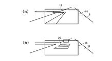
- (A) is an explanatory diagram illustrating an example in which a navigation arrow is displayed on a front windshield by the head-up display device in FIG. 1
- (b) is an explanatory diagram illustrating an example in which a guide indicating a distance between the vehicle and a preceding vehicle is displayed.
- FIG. 1 is an explanatory diagram illustrating a configuration of a head-up display device in FIG. 1.
- FIG. 2 is a block diagram illustrating a relationship among a display unit, an image generation unit, an object detection unit, and a vehicle information detection unit of the head-up display device in FIG. 1.
- (A) is an explanatory diagram illustrating an example in which a navigation arrow is displayed on
- FIG. 3 is a flowchart showing a virtual image display surface adjustment process by the head-up display device of FIG. 1.
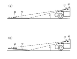
- FIG. 2A is an explanatory diagram illustrating a virtual image display surface of the head-up display device in FIG. 1
- FIG. 2B is an explanatory diagram illustrating a virtual image display surface when the front part of the vehicle floats and the rear part sinks.
- It is an explanatory view showing a vehicle provided with another head-up display device according to an embodiment of the present invention.
- (A) is an explanatory view showing a virtual image display surface of the conventional head-up display device
- (b) is an explanatory view showing the virtual image display surface when the front part of the vehicle in (a) floats and the rear part sinks.
- (A) is a figure for explaining magnification and a focus of a head-up display device
- (b) is a figure for explaining a relation between a viewer's eye point and a virtual image position.
- (A) is a figure which shows the virtual image display using the virtual image display surface by another example of a head-up display apparatus
- (b) is a figure which shows the example of the image displayed on the display surface of an image display part.
- (A) is a diagram for explaining the features of the virtual image display surface
- (b), (c), (c ′), and (d) are diagrams showing examples in which the positional relationship between the virtual image display surface and the road surface position is different. It is. It is a figure showing an example of an optical system in a head up display device.
- FIG. 14 is a diagram illustrating another example of the optical system in the head-up display device (an example in which the angle of the concave mirror is fixed and the use area on the reflection surface is changed in accordance with the vertical movement of the eye point).
- FIG. 7 is a diagram for describing a specific example in a case where a use area on a reflection surface of a concave mirror is changed, and a design feature of the reflection surface.
- FIG. 7 is a diagram illustrating a state in which a road surface is superimposed and displayed as a superimposed object (actual scene) when the vehicle is traveling on a straight road;
- (A)-(c) is a figure which shows a mode that a virtual image display position changes according to the change of the convergence angle difference in the head-up display apparatus, and the change of an eye point.
- (A), (b) is a figure for demonstrating the relationship between a virtual image display distance and a convergence angle difference.
- FIG. 2 is a diagram illustrating an example of a system configuration of a head-up display device.
- a head-up display device (HUD) 1 As shown in FIG. 1, a head-up display device (HUD) 1 according to the present embodiment is provided inside a dashboard 4 located below a front windshield 3 of a vehicle 2, The display light 5 is projected onto the section. The display light 5 is reflected by the front windshield 3 to generate a virtual image 6, and allows a viewer (driver) 7 to visually recognize the virtual image 6 so as to be superimposed on an actual scene transmitted through the front windshield 3.
- the virtual image 6 is displayed on a virtual image display surface 9 located below a road surface 8 on which the vehicle 2 travels, as described later in detail.
- the HUD 1 is schematically configured such that a display unit 12, a reflecting mirror 13, and an image generation unit 14 are provided inside a case 11 in which a light transmitting unit 10 is formed.
- the display unit 12 includes a projection unit 15 including a projector using a reflective display device such as DMD or LCoS, and receives projection light from the projection unit 15 and emits display light 5 including an image to the reflection mirror 13. And a screen 16 for performing the operation.
- the display light 5 from the display unit 12 is reflected by the concave reflecting mirror 13, passes through the light transmitting unit 10, and is projected on the front windshield 3.
- the display light 5 projected on the front windshield 3 is reflected to the viewer 7 side, generates a virtual image 6 and displays it on the viewer 7 (see FIG. 1).
- the reflecting mirror 13 may be capable of changing a projection position of the display light 5 on the front windshield 3 by being rotationally driven by a driving mechanism (not shown). And the like.
- the image generation unit 14 includes a microcomputer, a GDC, and the like, and is connected to the display unit 12 and an in-vehicle LAN bus 27 such as a CAN, as shown in FIG.
- the bus 27 includes an object detection unit 16 that detects a road surface 8 on which the vehicle 2 travels and other objects around the vehicle by a camera, LiDAR, V2X, or the like, a CAN transceiver IC, a GNSS, an acceleration sensor, a motion sensor, and a gyro sensor.
- a vehicle information detecting unit 17 for detecting vehicle speed, acceleration, and other vehicle information is connected to the vehicle.
- the virtual image 6 generated by the display light 5 is attached to the road surface 8 on which the vehicle 2 travels and is visually recognized, and is a navigation arrow displayed in the display area 18 of the front windshield 3 shown in FIG. 19 and a guide 20 indicating the distance between the vehicle and a preceding vehicle (the preceding vehicle is visually recognized by the viewer 7 as a real scene) shown in FIG.
- the image generation unit 14 projects the display light 5 so that the virtual image display surface 9 is substantially parallel to the road surface 8 and is positioned below the road surface 8 (see FIG. 1), and the virtual image is displayed.
- the display surface 9 is located at a predetermined depth (50 to 200 cm below the road surface 8) on the road surface 8 that is far (forward) from the vehicle 2 by a predetermined distance (20 to 50 m).
- the image generating unit 14 adjusts the position of the virtual image display surface 9 with respect to the vehicle 2 so that the predetermined distance and / or the predetermined depth is maintained. . That is, the image generation unit 14 acquires the pitch angle of the vehicle from the detection result of the vehicle information detection unit 17 (acceleration sensor, motion sensor, gyro sensor, etc.) (Step 1 (described as “S.1” in FIG. 5). Based on the pitch angle and the predetermined distance and / or the predetermined depth, a display shifted from the desired display position (FIG. 6A) on the virtual image display surface 9 by the acquired pitch angle is performed. The amount of deviation from the position (FIG. 6B) is calculated (step 2). Then, the position of the virtual image display surface 9 with respect to the vehicle 2 is adjusted so as to cancel the shift amount (Step 3), and the display unit 12 is controlled to project the display light 5 corresponding to the virtual image display surface 9 after the adjustment. (Step 4).
- the vehicle information detection unit 17 acceleration sensor, motion sensor,
- the position of the virtual image display surface 9 is adjusted according to the change in the pitch angle actually generated by the image generation unit 14.
- the object detection unit 16 (camera, LiDAR, or the like) adjusts the road surface 8.
- the real-time property may be improved by detecting the shape, unevenness, and the like, taking into account the detection results, and estimating the pitch angle at the next moment to adjust the position of the virtual image display surface 9.
- the image generation unit 14 detects the road surface 8 by the object detection unit 16 or assumes that the height is the same as the height of the road surface on which the vehicle 2 touches the ground. To grasp the height of the road surface 8.
- the virtual image display surface 9 is located below the road surface 8 on which the vehicle 2 travels, and the virtual image 6 is also displayed below the road surface 8. From the prejudice that the road surface 8 has no further depth side, it is visually recognized that the road surface 8 is stuck to the road surface 8. This tendency is particularly noticeable as the virtual image display surface 9 and the virtual image 6 are located farther from the vehicle 2. Depth perception becomes insensitive and remarkable. That is, although the virtual image 6 is actually formed on the far side (below) of the road surface 8 when viewed from the viewer 7, the viewer 7 feels as if the virtual image 6 is stretched on the surface of the road surface 8. Perceive as if it were displayed.
- the pitch angle of the vehicle 2 changes when there is no function of adjusting the position of the virtual image display surface 9 by the image generation unit 14, or when the pitch angle of the vehicle 2 changes beyond the assumption of the position adjustment function
- the virtual image display surface 9 rises as shown in FIGS. 6A and 6B
- the virtual image display surface 9 that has been positioned below the road surface 8 is still positioned below the road surface 8 even if it has floated.
- the virtual image 6 appears to the viewer 7 as sticking to the road surface 8, and the sense of overlap with the road surface 8 is not lost.
- the HUD 1 it is possible to stably display the virtual image 6 sticking to the road surface 8 even if the pitch angle of the vehicle 2, the shape of the road surface 8, or the unevenness of the vehicle 2 changes while the vehicle 2 is running.
- the image generation unit 14 adjusts the position of the virtual image display surface 9 with respect to the vehicle 2 so as to be constant, so that the virtual image display surface 9 itself is prevented from rising from the road surface 8 and the virtual image viewed from the viewer 7. Since the virtual image 6 is displayed at a fixed location, the virtual image 6 is displayed more stably on the road surface 8 when the vehicle 2 is traveling, and the visibility is improved.
- FIG. 7 shows a vehicle 2 provided with another HUD 21 according to the present embodiment.
- the HUD 21 has the same configuration as the HUD 1 except that the image generated by the image generation unit is different, and thus a detailed description of each unit is omitted.
- the end 23 on the far side (upper side as viewed from the viewer 7) with respect to the vehicle 2 is positioned higher than the end 24 on the near side (lower side as viewed from the viewer 7). And above the road surface 8.
- an end 24 on the near side to the vehicle 2 is located below the road surface 8
- a portion of the virtual image display surface 22 above the road surface 8 includes a background-related virtual image (vehicle speed or The remaining distance to the next guidance point by the navigation, an image of FCW (forward collision warning) 25, etc.) are displayed, and a portion below the road surface 8 is superimposed on the road surface 8 so as to stick to the road surface 8.
- the road surface related virtual image 26 visually recognized is displayed.
- the far end 23 of the virtual image display surface 22 is located above the road surface 8 and the near end 24 is located below the road surface 8.
- the road-related virtual image 26 superimposed on the background on the road surface 8 can be displayed on the side of the end 24 while the road-related virtual image 26 that is visually recognized is displayed on the side of the end 23.
- the configuration of the display unit and other components of the HUD is arbitrary as long as at least a part of the virtual image display surface can be positioned below the road surface on which the vehicle travels.
- the display position of the virtual image display surface and the display content of the virtual image are also arbitrary.
- the angle formed by the virtual image display surface and the road surface even if the virtual image display surface is substantially parallel to the road surface 8 as in the virtual image display surface 9, as in the virtual image display surface 22. It may be substantially perpendicular to the road surface 8 or another angle.
- the virtual image display surface is generally in a lying state (close to being parallel to the road surface). It is desirable that the distance from the vehicle to the virtual image display surface is the predetermined distance (20 to 50 m) and the depth from the road surface to the virtual image display surface is the predetermined depth (50 to 200 cm). ), The virtual image is visually recognized as being sufficiently stuck to the road surface, and rises from the road surface due to a change in the pitch angle of the vehicle, a change in the shape of the road surface, or a change in the unevenness of the vehicle under normal driving conditions of the vehicle. It is also prevented from seeing.
- FIG. 9 is a diagram for explaining a magnification and a focus of the head-up display device
- FIG. 9B is a diagram for explaining a relationship between an eye point of a viewer and a virtual image position.
- An optical path length a is defined as a distance from a viewpoint E (or a predetermined position of the vehicle) of a person (viewer) to a virtual image V (or a reference point on the virtual image display surface) is defined as a virtual image display distance b.
- a viewpoint E or a predetermined position of the vehicle
- V or a reference point on the virtual image display surface
- the size of the display surface of the image display unit increases, the size of optical members such as a concave mirror also increases, and the display light shines on the largely curved peripheral region of the concave mirror. Therefore, for example, when a flat road surface is set as an object to be superimposed and a navigation display (an arrow having a flat surface or the like) is superimposed and displayed on the road surface, the navigation display (virtual image) is completely flat. Cannot be displayed properly. In other words, it is difficult to superimpose the navigation display (virtual image) on the road surface while ensuring complete flatness over the entire angle of view.
- the image M is displayed on the display surface of the image display unit S, and a virtual image is displayed via the concave mirror WD and the front shield (reflective translucent member) T.
- the eye point EP (C) of the viewer (the driver of the vehicle or the like) is located at the center of the eye box EB.
- the virtual image display surfaces corresponding to the left and right eyes are PLN (L) and PLN (R)
- the virtual image V (C) is located at the center of the overlapping area.
- FIG. 10A is a diagram illustrating a virtual image display using a virtual image display surface according to another example of the head-up display device
- FIG. 10B is a diagram illustrating an example of an image displayed on the display surface of the image display unit. is there.
- the direction along the front of the vehicle 200 (also referred to as the front-back direction) is defined as the Z direction
- the direction along the width (lateral width) of the vehicle 200 is defined as the X direction
- the height of the vehicle 200 is defined as the X direction
- the vertical direction (the direction perpendicular to the flat road surface 80 and away from the road surface 80) is defined as the Y direction.
- a direction along a line segment (normal line) perpendicular to the road surface 80 is defined as an up-down direction.
- the vertical downward direction is downward, and the opposite direction is upward.
- an arrow mark is a virtual image having a linearly extending portion (extending component) extending in a direction coinciding with the extending direction of the road surface 80.
- a type of display 501 is displayed.
- the arrow mark 501 as a virtual image is a flat mark (in other words, a mark having a flat surface), and is displayed so as to overlap the road surface 80 with the road surface 80 as an object to be superimposed.
- this is a virtual image of content superimposed (referred to as superimposed content).
- J1 indicates an end point of the arrow mark 501 farther from the vehicle 200
- J3 indicates an end point closer to the vehicle 200
- J2 indicates an end point between J1 and J2.
- a HUD device (sometimes referred to as a road surface superimposed HUD) 101 of the present embodiment having display characteristics suitable for displaying a virtual image on the road surface is mounted. Have been.
- the HUD device 101 includes an image display unit (here, a screen) 160 having a display surface 164 that displays an image, and an optical member that projects display light 50 that displays an image onto a windshield 300 that is a reflective translucent member.
- the optical member has a concave mirror (magnifying reflector) 130 having a reflection surface 139, and the reflection surface 139 of the concave mirror 130 has It has a shape (including a curved surface) suitable for displaying a virtual image (here, an arrow mark 501) with the road surface 80 as an object to be superimposed, and is drawn by a thick line on the virtual image display surface 400 (lower left side in FIG. 10). ) Is determined according to the shape of the reflection surface 139.
- the shape of the virtual image display surface 400 is not limited to the shape (including the curved surface) of the reflection surface 139 of the concave mirror 130, the curved shape of the windshield 300, and other optical members (for example, a correction mirror) mounted in the optical system 120. ) Is also affected. In addition, it is affected by the shape of the display surface 164 (generally flat, but the whole or a part may be non-planar) and the arrangement of the display surface 164 with respect to the reflection surface 139.
- the concave mirror 130 is a magnifying reflection mirror, and has a large effect on the shape of the virtual image display surface 400. If the shape of the reflection surface 139 of the concave mirror 130 is different, the shape of the virtual image display surface 400 is actually changed. Therefore, the shape of the concave virtual image display surface 400 also depends on the shape of the reflection surface 139 of the concave mirror 130.
- a real image (real image) RE (501) of an arrow is displayed on the image display surface 164.
- the real image RE (501) of this arrow takes full advantage of the range of the angle of view of the image display unit 160, and the one end (first display limit end) 503 of the image display area 163 and the other end on the opposite side.
- the second display limit end) 504 is arranged as an image of an arrow mark having a linearly continuous portion.
- the extending direction NP can be referred to as (corresponding to) a direction along the Z direction which is a forward direction (front-back direction) in the real space. Since the display makes full use of the angle of view, the display light also shines on the peripheral area of the concave mirror 130 where the change in curvature can be large.
- the virtual image display surface 400 has a curved cross-sectional shape.
- the HUD device 101 displays the virtual image 501 so as to be superimposed on the road surface 80 with the road surface 80 as the object to be superimposed.
- the virtual image display surface 400 may be entirely or partially located below the road surface 80, or may be entirely located on the road surface.
- FIG. 10A shows an example in which a part is below the road surface 80.
- the size of the virtual image display surface 400 is determined according to the size of the image display area (effective display area) 163 corresponding to the angle of view of the HUD device 101.
- the virtual image of the image when an image is displayed using the size of the image display area 163 to the maximum, the virtual image of the image extends along the road surface, but the virtual image of the image depends on the aberration of the concave mirror and the windshield. It becomes a shape having a concave curved surface which is curved, and the concave shape adjusts the characteristics of the optical system 120 typified by the concave mirror 130, as appropriate, in detail, with high accuracy, and thereby reduces the entire shape of the virtual image display surface. Can be controlled.
- the virtual image display surface 400 includes an end 406 on the near side (including the end point Q3 on the side closer to the vehicle), a far end 403 (including the end point Q1 on the far side) with respect to the vehicle 200, and an end on the near side. And a central portion 405 (including the end point Q2) located between the 406 and the far end 403.
- the central portion is, in other words, an intermediate portion, and may be referred to as a middle region, a central region, or the like.
- a part (the end 403 on the far side and the center 405) of the virtual image display surface 400 is located below the road surface 80.
- the far end 403 has a shape that is substantially parallel to the road surface 80, so that the overlapping property on the road surface 80 is enhanced.
- the far end 403 has a higher flatness than the near end 406.
- the optical characteristics of the entire region or a part of the optical system 120 are adjusted, and the arrangement of the optical member (for example, the concave mirror 130) and the display surface 164 is adjusted.
- the shape of the virtual image display surface 400 can be formed by performing, adjusting the shape of the display surface 164, or a combination thereof.
- the shape of the reflection surface including the curved surface in the concave mirror (magnifying reflection mirror) 130 can be appropriately adjusted (designed) so as to cause the shape of the virtual image display surface 400.
- the change in curvature and the flatness of the surface can be appropriately adjusted.
- FIG. 11A is a diagram for explaining the characteristics of the virtual image display surface
- FIGS. 11B, 11C, 11C, and 11D show different positional relationships between the virtual image display surface and the road surface position. It is a figure showing an example.
- the virtual image display surface 400 shown in FIG. 11A has an end near the vehicle 200 (near end, first end) 406 and a far end (far end). (Second end) 403.
- the virtual image display surface 400 has no portion below the road surface 80.
- the virtual image display surface 400 is a curved surface in which the near end (first end) 406 is located above the road surface 80, and the vehicle at the near end (first end) 406
- the end point Q3 closest to 200 is located at the highest position (the position in the most positive direction on the Y-axis in FIG. 10) of the virtual image display surface 400 (the distance from the road surface 80 (in other words, the rising of the road surface). Height) is the largest in the virtual image display surface 400) and at least a part of the far end (second end) 403 (almost all in the case of FIG. 11A) is: It has a shape that is flatter than the end (first end) 406 on the near side so as to overlap the road surface 80.
- the far end 403 has a shape that is substantially parallel to the road surface 80, and the overlapping property on the road surface 80 is enhanced.
- the far end 403 has a higher flatness than the near end 406. Therefore, the virtual image (for example, the arrow mark 501 in the example of FIG. 10) displayed on the far end 403 is the far end including important information (that is, the portion of the arrow indicating the directionality). Can be perceived by a viewer as if it were completely stuck to the road surface 80.
- the far end can be perceived as having a very small change in position in the vertical direction (the direction along the normal to the road surface), so that the flatness is secured and the appearance is good.
- the central portion 405 of the virtual image display surface 400 also has a sufficiently high flatness, and the floating from the road surface 80 is suppressed.
- the floating of the image with respect to the road surface 80 is easily perceived by a viewer, and a sense of discomfort is likely to occur. Therefore, even when the pitching angle of the vehicle 200 with respect to the road surface 80 changes, the far side (the entire virtual image display surface) is shifted upward from the road surface by keeping the far side of the virtual image display surface 400 flat and suppressing the floating. Can be suppressed.
- the shape (cross-sectional shape) of the virtual image display surface 400 is the same, but the position of the road surface (ground) is different.
- 11B similarly to the example of FIG. 11A, the virtual image display surface 400 does not have a portion located below the road surface 80. The far end point Q1 is accurately superimposed on the road surface 80.
- the far end point Q1 and the center point Q2 of the virtual image display surface 400 are located below the road surface 80.
- the end point Q3 on the near side is located at a position distant from the road surface 80 (that is, at a slightly raised position).
- the lifting of the near end point Q3 from the road surface 80 is considerably suppressed, and no adverse effect such as a decrease in flatness occurs. It is considered.
- the human eye corrects the position of the virtual image on the road surface from the viewpoint that the virtual image does not fall below the road surface. Tend to be positioned. Therefore, a portion located below the road surface can be perceived as if it is completely superimposed on the road surface 80.
- the virtual image display surface 400 of the present embodiment has improved flatness particularly near the far end (that is, the degree of curvature is extremely low). Therefore, it can be said that fluctuations in the vertical direction (height direction) are sufficiently suppressed as a whole. Taking into account the effect of visual averaging, the virtual image can be perceived flat without any discomfort.
- the distance dp2 between the road surface 80 and the second end 403 (here, the end point Q1) is the distance between the road surface 80 and the first end 406 (here, the virtual image display surface 400). Is set to be longer than the distance dp1 to the end point Q3), that is, dp2> dp1 is satisfied.
- the lifting of the near end (first end) 406 can be further suppressed, and the far end (second end) 403 is disposed above the road surface 80. Can be improved.
- the far end 403 of the present embodiment is located at the lowest position (the most negative direction on the Y axis in FIG. 10) of the virtual image display surface 400. Position).
- the virtual image display surface 400 is formed such that the position in the height direction becomes lower in the order of the end 406 on the near side, the center 405, and the end 403 on the far side. Therefore, even when the attitude (pitching angle) of the vehicle 200 changes, the far end 403 can be prevented from being disposed above the road surface 80, and the far end can be suppressed due to the change in the attitude of the vehicle 200. Even when the portion 403 is arranged above the road surface 80, the distance in the height direction between the far side (the entire virtual image display surface) and the road surface 80 can be reduced.
- the distance between the road surface 80 and the second end 403 is small.
- the distance (in other words, the distance recessed downward from the road surface: dp2 in FIG. 11C) is the distance between the road surface 80 and the end (first end) 403 on the near side (in other words, the distance from the road surface).
- the virtual image display surface 400 may be formed so as to be longer than the rising height (dp1 in FIG. 11 (c ′)) or the distance below the road surface (FIG. 11 (d)).
- the lifting of the near end (first end) 406 can be further suppressed, and the far end (second end) 403 is disposed above the road surface 80. Can be suppressed.
- the far end 403 is not limited to a shape with higher flatness than the near end 406. That is, in some embodiments, the distal end 403 can be shaped similar to, or less flat than, the proximal end 406. Furthermore, if the virtual image display surface 400 is formed so that the position in the height direction becomes lower in the order of the end portion 406 on the near side, the center portion 405, and the end portion 403 on the far side, the virtual image display surface 400 has a curved surface shape. (The cross-sectional shape of the virtual image display surface 400 in the YZ plane may not be a curved shape.)
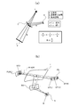
- FIG. 12 is a diagram illustrating an example of an optical system in a head-up display device.
- the HUD device 121 includes a light projecting unit 151, a screen 161 as an image display unit, a reflecting mirror 133, a concave mirror 131, an I / O interface for acquiring information from an external sensor or another ECU, a processor, a memory, And a control unit 171 (also referred to as a display control device) configured from a computer program stored in the memory.
- the angle of the concave mirror 131 can be appropriately adjusted by the operation of the rotation mechanism 175 including an actuator. Further, the inclination and the position of the screen 161 can be appropriately adjusted by the adjusting unit 173 including an actuator of the image display unit.
- the inclination of the screen 161 is, specifically, an inclination with respect to the optical axis of the light projecting unit 151, an inclination with respect to the optical axis of the optical system, or an inclination with respect to a main optical path (principal ray) of light emitted from the light projecting unit. It can be said.
- the control unit 171 generally controls the operation of the light projecting unit 151, the operation of the rotation mechanism 175, the operation of the adjustment unit 173 of the image display unit, and the like. Note that reference numeral 51 indicates outgoing light.
- FIG. 13 is a diagram for explaining an example of a shape of a concave mirror (an enlarged reflecting mirror having a reflecting surface including a curved surface) and a focal point.
- the concave mirror 135 shown in FIG. 13 has each part of ⁇ , ⁇ , and ⁇ , and the radius of curvature of each part is generally set to large, small, and small.
- Reference numeral 163 indicates a screen as an image display unit.
- An optical path indicated by a broken line indicates a main optical path (main ray) along the optical axis of the concave mirror 135 (optical system in a broader sense).
- the concave mirror 135 has focal points indicated by points F1 to F5 according to the change in the radius of curvature of the concave mirror 135.
- the shape (degree of curvature, flatness, etc.) of the virtual image display surface 400 can be changed according to the shape including the curved surface indicated by the locus of the focal point. For example, various variations are conceivable, such as finely adjusting the radius of curvature of each part of ⁇ , ⁇ , and ⁇ of the concave mirror 135 in a stepwise manner, or changing it continuously.
- the shape including the curved surface of the virtual image display surface is allowed, and the shape including the curved surface is controlled with high precision and freedom.
- FIG. 14 is a diagram illustrating another example of the optical system in the head-up display device.
- the optical system 121 ′ includes a light projecting unit 151 ′, a screen 161 ′ as an image display unit, a reflecting mirror (which can also be used as a correcting mirror) 133 ′, a concave mirror 131 ′, an external sensor and other sensors.
- a control unit 171 ′ (also referred to as a display control device) including an I / O interface for acquiring information from the ECU, a processor, a memory, and a computer program stored in the memory; an adjustment unit 173 ′; Having. The inclination and the position of the screen 161 as the image display unit can be appropriately adjusted by the adjustment unit 173 '(this point is the same as the example in FIG. 12).
- the example of FIG. 14 does not include a rotation mechanism for adjusting the inclination angle of the concave mirror 131 '. That is, the angle of inclination of the concave mirror 131 'is fixed (however, it is possible to change the angle of inclination in the initial setting).
- the viewpoint (eye point) 70 may change in the vertical direction (the height direction of the vehicle) in accordance with the height and the height of the sitting height of the viewer. It is necessary to adaptively change the optical axis (principal optical path, principal ray) of the optical system 121 'in response to this change in the viewpoint (eye point).
- the screen 161 ', the reflecting mirror 133', and the concave mirror 131 ' are larger than those in the example of FIG.
- the main optical path (principal ray) of the light emitted from the light projecting unit 151 ′ is switched according to the vertical change of the viewpoint (eye point) 70.
- the optical axis of the optical system 121) ' can be adjusted in accordance with a change in the vertical direction (height direction) of the viewpoint (eye point) 70.
- the reason why the mechanism for rotating the concave mirror 131 ′ is not provided is that the display characteristics of the HUD device may fluctuate due to an error in the rotation.
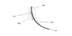
- FIG. 15 is referred.
- FIG. 7 is a diagram for describing a specific example in a case where a use area on a reflection surface of a concave mirror is changed, and a design feature of the reflection surface.
- the main optical path (principal ray) of the light emitted from the light projecting unit 151 ′ is switched according to the vertical change of the viewpoint (eye point) 70.
- the area used for light reflection on the reflecting surface of the concave mirror 131 ' also changes.
- FIG. 15 shows two use areas Ze1 and Ze2.
- a region 605 where the two regions Ze1 and Ze2 overlap (a region having an overlap) 605 and a region 607 which does not overlap (a region having no overlap) are generated.
- the curvature of the reflective surface in the overlapping area 605 greatly affects the shape of the end near the virtual image display surface.
- the region Ze1 when adopted, it has a great effect on the shape of the far end of the virtual image display surface.
- the design is made with priority given to enhancing the flatness of the shape of the far end of the virtual image display surface, assuming that the region Ze1 is applied. That is, the shape of the reflection surface in the overlapping area 605 is suitable for forming the shape of the end portion (the end portion on the far side, the second end portion) of the virtual image display surface 400 remote from the vehicle 200 into a desired shape. Shape.
- FIG. 16 is a diagram illustrating a state in which a road surface is superimposed and displayed as a superimposed object (actual scene) when the vehicle is traveling on a straight road.
- the vehicle is traveling straight on a straight road with good visibility.
- a virtual image 507 for navigation is displayed (arranged) so as to overlap the road surface 80.
- the virtual image display area 305 is a square, and the side in the width direction (lateral direction) of the vehicle is longer than the side in the height direction (vertical direction) of the vehicle, and is a horizontally long rectangle.
- the convergence angle causes a phenomenon in which the virtual image is perceived as inconsistent with the road surface, or the eye point is shifted due to the fact that the viewpoint of the person is shifted in the left-right direction (see FIG. 9B).
- the possibility of occurrence of a phenomenon or the like in which the displacement appears to be enlarged due to the change in the position of the virtual image due to the movement of (1) increases. According to the above-described embodiment, it is possible to effectively cope with these positional deviations (drawing positional deviations described later).
- a specific description will be given.
- FIGS. 17A to 17C are diagrams showing how the virtual image display position changes in response to a change in the convergence angle difference and a change in the eye point in the head-up display device.
- ⁇ HUD indicates the convergence angle of both eyes (left eye 70L, right eye 70R) at the HUD focal position PC0
- ⁇ scene is the actual scene that should originally match the HUD focal position PC0.
- the convergence angle at the point PC1 of the road surface (road surface as a superimposition target) 80 is shown.
- ⁇ scene (far) is the convergence angle for the point PC2 at a greater distance from the vehicle (ie, located farther).
- a point (closer end point) P11 closest to the vehicle (or the viewer) on the virtual image display surface 400 corresponds to the imaging point PC1 in FIG. 17A. If the curvature at the end near the virtual image display surface 400 is greater, the end point P11 on the near side of the virtual image display surface 400 changes to the end point P12.
- the distance between the end point P11 and the point PC1 on the road surface 80 is D11, and this D11 indicates a distance shift.
- the distance deviation between the end point P12 and the point PC2 on the road surface 80 is D12 (> D11). In other words, if the curvature at the end near the virtual image display surface 400 is larger, the end point is further away from the road surface, and the distance shift is correspondingly increased.
- the difference between ⁇ HUD and ⁇ scene is referred to as a convergence angle difference.
- the convergence angle difference is equal to or less than (or less than) a predetermined value (threshold) ⁇ th. That is, the amount of displacement of the convergence angle caused by the shift between the virtual image forming point and the real scene (here, the road surface) corresponding to the virtual image forming point is equal to or smaller than the threshold ⁇ th (or smaller).
- a distance shift also referred to as a focus shift
- a part of the virtual image display surface 400 (the end on the far side, the center, the portion near the far end, etc.) is positioned below the road surface 80.
- the distance between the end point P11 and the road surface 80 (in other words, the lift amount of the end point P11) can be reduced. Therefore, it is possible to prevent ⁇ scene from becoming too small.
- ⁇ HUD is fixed. Therefore, it is possible to sufficiently suppress the convergence angle difference ( ⁇ HUD ⁇ scene). Therefore, a good-looking virtual image display (road surface superimposed display or the like) is realized. Specific numerical values of the threshold value ⁇ th will be described later.
- the distance between the end point P11 and the road surface 80 can be reduced. Therefore, in a HUD device having a wide viewing angle and a long virtual image display distance, for example, even when a virtual image is displayed in a wide range (a wide range extending from near to far), it is possible to display the whole without a sense of incongruity. Therefore, the reliability of the HUD device is improved.
- FIGS. 18A and 18B are diagrams for explaining the relationship between the virtual image display distance and the convergence angle difference.
- the distance between the focal position (imaging point) of the HUD device and the point on the road surface 80 corresponding to the imaging point is 1 m.
- the displacement is 1 m.
- the virtual image display distance DHUD is 5 m
- the virtual image display distance FHUD is 10 m.
- the convergence angle difference is 0.068 degrees
- the convergence angle difference is 0.034.
- the convergence angle difference is calculated with the distance between the pupils being 65 mm. If the amount of displacement is the same, the longer the virtual image display distance, the smaller the convergence angle difference. Therefore, it can be said that the problem of a decrease in the visibility of the virtual image caused by the convergence angle difference is likely to occur when the virtual image display distance is small.
- the viewpoint of the viewer of the virtual image that is the occupant of the vehicle is located at the center eye point in the left-right direction of the eye box, and the virtual image display distance A virtual image is displayed in front of 5 m or more, and the convergence angle for one point of the virtual image is defined as a first convergence angle ⁇ HUD, and the convergence angle for the point on the road surface that is the object to be superimposed corresponds to one point of the virtual image.
- the difference between the first convergence angle and the second convergence angle is the convergence angle difference
- the virtual image display distance is 5 m or more by setting the convergence angle difference to 0.068 degrees or less. In the virtual image display in the above, a decrease in visibility can be suppressed.
- the optical system includes the concave mirror (magnifying reflector), but the optical characteristic (including optical power) obtained by combining one or a plurality of optical members has an enlarging function.
- the present invention is not limited thereto, and one or more refractive optical members such as lenses, diffractive optical members such as holograms, reflective optical members, Alternatively, a combination of these may be included.
- the optical system of the present embodiment may change the optical characteristics of the optical member for each optical path through which a plurality of display lights for displaying a virtual image on each region of one or more virtual image display surfaces.
- FIG. 19 is a diagram illustrating an example of a system configuration of the head-up display device.
- the system illustrated in FIG. 19 includes a display control device 740, an object detection unit 801, a vehicle information detection unit 803, the display unit 12, a first actuator 177, and a second actuator 179.
- the display control device 740 includes an I / O interface 741, a processor 742, and a memory 743.
- the display control device 740, the object detection unit 801 and the vehicle information detection unit 803 are connected to a communication line (BUS or the like).
- the display control unit 740 can be used, for example, as the control unit 171 illustrated in FIG.
- the first actuator 177 and the second actuator 179 can be used as the rotation mechanism 179 and the adjustment unit 173 shown in FIG. 12, and individually adjust the entirety and details of the optical system 121 shown in FIG. It can also be used to do These can also be referred to as an adjustment system of the optical system.
- the object detection unit 801 can be configured by, for example, an external sensor and an external camera provided in the vehicle 2 (or 200). Further, the vehicle information detection unit 803 can be configured by, for example, a speed sensor, a vehicle ECU, an external communication device, a sensor for detecting the position of an eye, or a height sensor.
- the display control device 740 based on the detection information of the target object detection unit 801 and the information from the vehicle information detection unit 803, for example, operates the optical system optimally and performs the above-described superimposition on the road surface with a high degree of superimposition. It is also possible to realize a superimposed HUD.
- the one or more processors 742 may obtain, for example, the position of the road surface 80, and based on the position of the road surface 80, at least a part of the virtual image display surface 400 may be disposed below the road surface 80, At least one of the first and second actuators 173 and 175 can be driven.
- vehicle is to be interpreted in a broad sense, such as a vehicle (or a simulator simulating a vehicle).
- the HUD device of the present invention can be applied to an aircraft cockpit simulator and the like.
- the term road surface should be interpreted broadly, for example, as a reference surface.
Abstract
L'objectif de la présente invention est de fournir un dispositif d'affichage tête haute susceptible d'afficher de manière stable une image virtuelle qui peut être visuellement reconnue sur une surface de route lorsqu'un véhicule se déplace. Un dispositif d'affichage tête haute (101) selon la présente invention comprend un moyen d'affichage qui projette une lumière d'affichage (50) sur un élément de réflexion/transmission (300) installé dans un véhicule (200) et génère et affiche une image virtuelle par la lumière d'affichage (50) réfléchie dans l'élément de réflexion/transmission (300) de façon à chevaucher une vue réelle transmettant l'élément de réflexion/transmission (300). Une surface d'affichage d'image virtuelle (400) sur laquelle des images virtuelles doivent être affichées est disposée de telle sorte qu'une extrémité (403) sur le côté plus éloigné du véhicule doit être située plus bas qu'une extrémité (406) sur le côté plus proche du véhicule.
Priority Applications (1)
| Application Number | Priority Date | Filing Date | Title |
|---|---|---|---|
| JP2020529061A JP7375753B2 (ja) | 2018-07-05 | 2019-07-05 | ヘッドアップディスプレイ装置 |
Applications Claiming Priority (4)
| Application Number | Priority Date | Filing Date | Title |
|---|---|---|---|
| JP2018127944 | 2018-07-05 | ||
| JP2018-127944 | 2018-07-05 | ||
| JP2019124234 | 2019-07-03 | ||
| JP2019-124234 | 2019-07-03 |
Publications (1)
| Publication Number | Publication Date |
|---|---|
| WO2020009218A1 true WO2020009218A1 (fr) | 2020-01-09 |
Family
ID=69059373
Family Applications (1)
| Application Number | Title | Priority Date | Filing Date |
|---|---|---|---|
| PCT/JP2019/026798 WO2020009218A1 (fr) | 2018-07-05 | 2019-07-05 | Dispositif d'affichage tête haute |
Country Status (2)
| Country | Link |
|---|---|
| JP (1) | JP7375753B2 (fr) |
| WO (1) | WO2020009218A1 (fr) |
Cited By (1)
| Publication number | Priority date | Publication date | Assignee | Title |
|---|---|---|---|---|
| WO2022007826A1 (fr) * | 2020-07-08 | 2022-01-13 | 杜加价 | Dispositif d'affichage en perspective virtuelle d'angle mort à l'avant d'un véhicule et procédé basé sur un miroir concave/une lentille convexe |
Citations (7)
| Publication number | Priority date | Publication date | Assignee | Title |
|---|---|---|---|---|
| WO2009071139A1 (fr) * | 2007-12-05 | 2009-06-11 | Audi Ag | Dispositif d'affichage pour véhicule automobile |
| JP2016053690A (ja) * | 2014-09-04 | 2016-04-14 | 矢崎総業株式会社 | 車両用投影表示装置 |
| JP2016064759A (ja) * | 2014-09-25 | 2016-04-28 | アイシン・エィ・ダブリュ株式会社 | 虚像表示装置 |
| WO2017134865A1 (fr) * | 2016-02-05 | 2017-08-10 | 日立マクセル株式会社 | Dispositif d'affichage tête haute |
| WO2018105585A1 (fr) * | 2016-12-09 | 2018-06-14 | 日本精機株式会社 | Dispositif d'affichage tête haute |
| WO2019004238A1 (fr) * | 2017-06-29 | 2019-01-03 | 日本精機株式会社 | Dispositif d'affichage tête haute |
| JP2019056840A (ja) * | 2017-09-21 | 2019-04-11 | パナソニックIpマネジメント株式会社 | ヘッドアップディスプレイ装置、及び車両 |
-
2019
- 2019-07-05 JP JP2020529061A patent/JP7375753B2/ja active Active
- 2019-07-05 WO PCT/JP2019/026798 patent/WO2020009218A1/fr active Application Filing
Patent Citations (7)
| Publication number | Priority date | Publication date | Assignee | Title |
|---|---|---|---|---|
| WO2009071139A1 (fr) * | 2007-12-05 | 2009-06-11 | Audi Ag | Dispositif d'affichage pour véhicule automobile |
| JP2016053690A (ja) * | 2014-09-04 | 2016-04-14 | 矢崎総業株式会社 | 車両用投影表示装置 |
| JP2016064759A (ja) * | 2014-09-25 | 2016-04-28 | アイシン・エィ・ダブリュ株式会社 | 虚像表示装置 |
| WO2017134865A1 (fr) * | 2016-02-05 | 2017-08-10 | 日立マクセル株式会社 | Dispositif d'affichage tête haute |
| WO2018105585A1 (fr) * | 2016-12-09 | 2018-06-14 | 日本精機株式会社 | Dispositif d'affichage tête haute |
| WO2019004238A1 (fr) * | 2017-06-29 | 2019-01-03 | 日本精機株式会社 | Dispositif d'affichage tête haute |
| JP2019056840A (ja) * | 2017-09-21 | 2019-04-11 | パナソニックIpマネジメント株式会社 | ヘッドアップディスプレイ装置、及び車両 |
Cited By (1)
| Publication number | Priority date | Publication date | Assignee | Title |
|---|---|---|---|---|
| WO2022007826A1 (fr) * | 2020-07-08 | 2022-01-13 | 杜加价 | Dispositif d'affichage en perspective virtuelle d'angle mort à l'avant d'un véhicule et procédé basé sur un miroir concave/une lentille convexe |
Also Published As
| Publication number | Publication date |
|---|---|
| JPWO2020009218A1 (ja) | 2021-08-12 |
| JP7375753B2 (ja) | 2023-11-08 |
Similar Documents
| Publication | Publication Date | Title |
|---|---|---|
| JP6377508B2 (ja) | 表示装置、制御方法、プログラム、及び記憶媒体 | |
| KR101759945B1 (ko) | 디스플레이 장치 | |
| WO2017163292A1 (fr) | Dispositif d'affichage tête haute, et véhicule | |
| JP7338625B2 (ja) | ヘッドアップディスプレイ装置 | |
| JP2010070066A (ja) | ヘッドアップディスプレイ | |
| US11215819B2 (en) | Head-up display | |
| CN110816408A (zh) | 显示装置、显示控制方法及存储介质 | |
| JP7310817B2 (ja) | ヘッドアップディスプレイ装置 | |
| JP2006195333A (ja) | 車載情報提供装置、および車載情報提供装置の制御方法 | |
| US11367418B2 (en) | Vehicle display device | |
| US20200124846A1 (en) | Display device | |
| US11604360B2 (en) | Head-up display | |
| WO2020009218A1 (fr) | Dispositif d'affichage tête haute | |
| JP2018120141A (ja) | ヘッドアップディスプレイ | |
| CN111727399B (zh) | 显示系统、移动体以及设计方法 | |
| WO2021002428A1 (fr) | Dispositif d'affichage tête haute | |
| JP7354846B2 (ja) | ヘッドアップディスプレイ装置 | |
| JP2022036432A (ja) | ヘッドアップディスプレイ装置、表示制御装置、及びヘッドアップディスプレイ装置の制御方法 | |
| JPWO2018199244A1 (ja) | 表示システム | |
| JP7279548B2 (ja) | ヘッドアップディスプレイ装置 | |
| JP2023104972A (ja) | 表示装置 | |
| JP2023120466A (ja) | 表示制御装置、表示装置、及び表示制御方法 | |
| JP2024048865A (ja) | 表示制御装置、表示装置 | |
| JP2019001459A (ja) | 表示装置 | |
| JP2023111754A (ja) | ヘッドアップディスプレイ装置 |
Legal Events
| Date | Code | Title | Description |
|---|---|---|---|
| 121 | Ep: the epo has been informed by wipo that ep was designated in this application |
Ref document number: 19830226 Country of ref document: EP Kind code of ref document: A1 |
|
| ENP | Entry into the national phase |
Ref document number: 2020529061 Country of ref document: JP Kind code of ref document: A |
|
| NENP | Non-entry into the national phase |
Ref country code: DE |
|
| 122 | Ep: pct application non-entry in european phase |
Ref document number: 19830226 Country of ref document: EP Kind code of ref document: A1 |