WO2020009218A1 - Head-up display device - Google Patents
Head-up display device Download PDFInfo
- Publication number
- WO2020009218A1 WO2020009218A1 PCT/JP2019/026798 JP2019026798W WO2020009218A1 WO 2020009218 A1 WO2020009218 A1 WO 2020009218A1 JP 2019026798 W JP2019026798 W JP 2019026798W WO 2020009218 A1 WO2020009218 A1 WO 2020009218A1
- Authority
- WO
- WIPO (PCT)
- Prior art keywords
- virtual image
- road surface
- image display
- vehicle
- display
- Prior art date
Links
Images


Classifications
-
- B—PERFORMING OPERATIONS; TRANSPORTING
- B60—VEHICLES IN GENERAL
- B60K—ARRANGEMENT OR MOUNTING OF PROPULSION UNITS OR OF TRANSMISSIONS IN VEHICLES; ARRANGEMENT OR MOUNTING OF PLURAL DIVERSE PRIME-MOVERS IN VEHICLES; AUXILIARY DRIVES FOR VEHICLES; INSTRUMENTATION OR DASHBOARDS FOR VEHICLES; ARRANGEMENTS IN CONNECTION WITH COOLING, AIR INTAKE, GAS EXHAUST OR FUEL SUPPLY OF PROPULSION UNITS IN VEHICLES
- B60K35/00—Arrangement of adaptations of instruments
-
- G—PHYSICS
- G02—OPTICS
- G02B—OPTICAL ELEMENTS, SYSTEMS OR APPARATUS
- G02B27/00—Optical systems or apparatus not provided for by any of the groups G02B1/00 - G02B26/00, G02B30/00
- G02B27/01—Head-up displays
Definitions
- the present invention relates to a head-up display device that displays a virtual image on a front windshield, a combiner, or the like of a vehicle.
- a head-up display device that superimposes on a real scene (a scene in front of the vehicle) that passes through a reflective translucent member such as a front windshield or a combiner of a vehicle and generates and displays a virtual image with display light reflected by the reflective translucent member. Contributes to safe and comfortable vehicle operation by providing the information desired by the viewer with a virtual image while minimizing the line of sight movement of the viewer driving the vehicle.
- a head-up display device described in Patent Document 1 is provided on a dashboard of a vehicle, projects display light on a front windshield, and gives a viewer a virtual image on a virtual image display surface by the display light reflected by the front windshield. Is visually recognized.
- the first virtual image is on a first virtual image display surface substantially parallel to the road surface on which the vehicle travels, and is on the second virtual image display surface substantially parallel to the direction perpendicular to the traveling direction of the vehicle.
- the second virtual image is displayed so as to form a predetermined angle.
- the first virtual image is visually recognized in a superimposed manner over a predetermined range of the road surface.
- the first virtual image display surface is located above the road surface (see paragraphs in the same patent document). 0015, FIG. 1), the viewer sees the first virtual image as if it were floating above the road surface.
- virtual images such as arrows indicating the route of the vehicle may not be visually recognized as floating from the road surface, but may be desirable to be viewed by sticking to the road surface. is there.
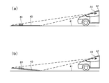
- the virtual image display surface 40 is positioned not above the road surface 41 but at the same height as the road surface 41 as shown in FIG. 8A, the road surface 41 is not If there is a change in the posture (change in the pitch angle) at 42, the virtual image display surface 40 floats above the road surface 41 and the virtual image 43 rises from the road surface 41 as shown in FIG. There was a problem that the viewer 44 could easily remember the uncomfortable feeling that 43 was not in harmony with the road surface 41.
- the present invention has been made in view of the above circumstances, and it is an object of the present invention to provide a head-up display device capable of stably displaying a virtual image stuck on a road surface when a vehicle is running.
- the display light is projected on a reflective translucent member provided in a vehicle, and a display reflected by the reflective translucent member is superimposed on an actual scene transmitted through the reflective translucent member.
- a head-up display device including a display unit that generates and displays a virtual image with light, an image display unit having a display surface that displays an image, and an optical member that projects the display light onto the reflective translucent member member
- the head-up display has a virtual image display surface that displays the virtual image, and the virtual image display surface has a first end closer to the vehicle and a remote end closer to the vehicle. A second end, wherein the second end is located lower than the first end; Further, the first end may be arranged at a highest position on the virtual image display surface.
- the virtual image display surface is a curved surface where the first end is located above the road surface, and The distance from the road surface of the end point closest to the vehicle at one end is the largest in the virtual image display surface, and at least a part of the second end portion overlaps the road surface, Adjusting the optical characteristics of the entire area or a partial area of the optical system, wherein the optical member and the display surface have a flattened shape higher than the first end;
- the shape of the virtual image display surface may be formed by adjusting the arrangement of the virtual image display surface, adjusting the shape of the display surface, or a combination thereof.
- the virtual image display surface may be partially or entirely including the second end portion located below the road surface.
- the virtual image display surface may be arranged such that a distance between the road surface and the second end is longer than a distance between the road surface and the first end. Further, the first and second ends may be located above the road surface. Further, the optical member may include a concave mirror having a curved reflecting surface, and a shape of the curved reflecting surface of the concave mirror may be adjusted to cause a shape of the virtual image display surface.
- a viewpoint of a viewer of the virtual image which is a passenger of the vehicle is located at a central eye point in the left-right direction of the eye box, and A virtual image is displayed in front of the display distance of 5 m or more, and a convergence angle for one point of the virtual image is defined as a first convergence angle, and a point on the road surface, which is an object to be superimposed, corresponding to one point of the virtual image.
- the convergence angle of the second convergence angle and the difference between the first convergence angle and the second convergence angle is the convergence angle difference, even if the convergence angle difference is 0.068 degrees or less Good.
- one or more actuators configured to move or / and rotate the display surface or / and the optical member, one or more I / O interfaces, and one or more A processor, a memory, and one or more computer programs stored in the memory and configured to be executed by the one or more processors; May obtain the position of the road surface, and may drive the actuator based on the position of the road surface such that at least a part of the virtual image display surface is disposed below the road surface.
- the reflection surface of the optical member has a first use area when an eye point of a viewer riding the vehicle is at a first position, and a position in the vertical direction is different from the first position.
- the shape of the second end on the far side may be a shape suitable for forming a desired shape.
- the entire virtual image can be arranged close to the road surface.
- a portion located far from the virtual image a distant portion, which can also be referred to as a tip portion
- a distant portion often has important information for a driver of the vehicle or the like (a viewer of the virtual image). Therefore, by adjusting the distant portion so that the flatness is increased so as to be closer to the road surface so as to overlap the road surface, visibility and recognition of the driver and the like can be improved.
- the nearby floating display can be brought as close as possible to the road surface. Therefore, the road surface superimposition property in the vicinity can be ensured.
- the head-up display device of the present invention it is possible to stably display a virtual image stuck on a road surface when the vehicle is running.
- FIG. 2 is an explanatory diagram illustrating a configuration of a head-up display device in FIG. 1.
- FIG. 2 is a block diagram illustrating a relationship among a display unit, an image generation unit, an object detection unit, and a vehicle information detection unit of the head-up display device in FIG. 1.
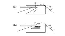
- (A) is an explanatory diagram illustrating an example in which a navigation arrow is displayed on a front windshield by the head-up display device in FIG. 1
- (b) is an explanatory diagram illustrating an example in which a guide indicating a distance between the vehicle and a preceding vehicle is displayed.
- FIG. 1 is an explanatory diagram illustrating a configuration of a head-up display device in FIG. 1.
- FIG. 2 is a block diagram illustrating a relationship among a display unit, an image generation unit, an object detection unit, and a vehicle information detection unit of the head-up display device in FIG. 1.
- (A) is an explanatory diagram illustrating an example in which a navigation arrow is displayed on
- FIG. 3 is a flowchart showing a virtual image display surface adjustment process by the head-up display device of FIG. 1.
- FIG. 2A is an explanatory diagram illustrating a virtual image display surface of the head-up display device in FIG. 1
- FIG. 2B is an explanatory diagram illustrating a virtual image display surface when the front part of the vehicle floats and the rear part sinks.
- It is an explanatory view showing a vehicle provided with another head-up display device according to an embodiment of the present invention.
- (A) is an explanatory view showing a virtual image display surface of the conventional head-up display device
- (b) is an explanatory view showing the virtual image display surface when the front part of the vehicle in (a) floats and the rear part sinks.
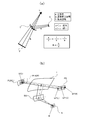
- (A) is a figure for explaining magnification and a focus of a head-up display device
- (b) is a figure for explaining a relation between a viewer's eye point and a virtual image position.
- (A) is a figure which shows the virtual image display using the virtual image display surface by another example of a head-up display apparatus
- (b) is a figure which shows the example of the image displayed on the display surface of an image display part.
- (A) is a diagram for explaining the features of the virtual image display surface
- (b), (c), (c ′), and (d) are diagrams showing examples in which the positional relationship between the virtual image display surface and the road surface position is different. It is. It is a figure showing an example of an optical system in a head up display device.
- FIG. 14 is a diagram illustrating another example of the optical system in the head-up display device (an example in which the angle of the concave mirror is fixed and the use area on the reflection surface is changed in accordance with the vertical movement of the eye point).
- FIG. 7 is a diagram for describing a specific example in a case where a use area on a reflection surface of a concave mirror is changed, and a design feature of the reflection surface.
- FIG. 7 is a diagram illustrating a state in which a road surface is superimposed and displayed as a superimposed object (actual scene) when the vehicle is traveling on a straight road;
- (A)-(c) is a figure which shows a mode that a virtual image display position changes according to the change of the convergence angle difference in the head-up display apparatus, and the change of an eye point.
- (A), (b) is a figure for demonstrating the relationship between a virtual image display distance and a convergence angle difference.
- FIG. 2 is a diagram illustrating an example of a system configuration of a head-up display device.
- a head-up display device (HUD) 1 As shown in FIG. 1, a head-up display device (HUD) 1 according to the present embodiment is provided inside a dashboard 4 located below a front windshield 3 of a vehicle 2, The display light 5 is projected onto the section. The display light 5 is reflected by the front windshield 3 to generate a virtual image 6, and allows a viewer (driver) 7 to visually recognize the virtual image 6 so as to be superimposed on an actual scene transmitted through the front windshield 3.
- the virtual image 6 is displayed on a virtual image display surface 9 located below a road surface 8 on which the vehicle 2 travels, as described later in detail.
- the HUD 1 is schematically configured such that a display unit 12, a reflecting mirror 13, and an image generation unit 14 are provided inside a case 11 in which a light transmitting unit 10 is formed.
- the display unit 12 includes a projection unit 15 including a projector using a reflective display device such as DMD or LCoS, and receives projection light from the projection unit 15 and emits display light 5 including an image to the reflection mirror 13. And a screen 16 for performing the operation.
- the display light 5 from the display unit 12 is reflected by the concave reflecting mirror 13, passes through the light transmitting unit 10, and is projected on the front windshield 3.
- the display light 5 projected on the front windshield 3 is reflected to the viewer 7 side, generates a virtual image 6 and displays it on the viewer 7 (see FIG. 1).
- the reflecting mirror 13 may be capable of changing a projection position of the display light 5 on the front windshield 3 by being rotationally driven by a driving mechanism (not shown). And the like.
- the image generation unit 14 includes a microcomputer, a GDC, and the like, and is connected to the display unit 12 and an in-vehicle LAN bus 27 such as a CAN, as shown in FIG.
- the bus 27 includes an object detection unit 16 that detects a road surface 8 on which the vehicle 2 travels and other objects around the vehicle by a camera, LiDAR, V2X, or the like, a CAN transceiver IC, a GNSS, an acceleration sensor, a motion sensor, and a gyro sensor.
- a vehicle information detecting unit 17 for detecting vehicle speed, acceleration, and other vehicle information is connected to the vehicle.
- the virtual image 6 generated by the display light 5 is attached to the road surface 8 on which the vehicle 2 travels and is visually recognized, and is a navigation arrow displayed in the display area 18 of the front windshield 3 shown in FIG. 19 and a guide 20 indicating the distance between the vehicle and a preceding vehicle (the preceding vehicle is visually recognized by the viewer 7 as a real scene) shown in FIG.
- the image generation unit 14 projects the display light 5 so that the virtual image display surface 9 is substantially parallel to the road surface 8 and is positioned below the road surface 8 (see FIG. 1), and the virtual image is displayed.
- the display surface 9 is located at a predetermined depth (50 to 200 cm below the road surface 8) on the road surface 8 that is far (forward) from the vehicle 2 by a predetermined distance (20 to 50 m).
- the image generating unit 14 adjusts the position of the virtual image display surface 9 with respect to the vehicle 2 so that the predetermined distance and / or the predetermined depth is maintained. . That is, the image generation unit 14 acquires the pitch angle of the vehicle from the detection result of the vehicle information detection unit 17 (acceleration sensor, motion sensor, gyro sensor, etc.) (Step 1 (described as “S.1” in FIG. 5). Based on the pitch angle and the predetermined distance and / or the predetermined depth, a display shifted from the desired display position (FIG. 6A) on the virtual image display surface 9 by the acquired pitch angle is performed. The amount of deviation from the position (FIG. 6B) is calculated (step 2). Then, the position of the virtual image display surface 9 with respect to the vehicle 2 is adjusted so as to cancel the shift amount (Step 3), and the display unit 12 is controlled to project the display light 5 corresponding to the virtual image display surface 9 after the adjustment. (Step 4).
- the vehicle information detection unit 17 acceleration sensor, motion sensor,
- the position of the virtual image display surface 9 is adjusted according to the change in the pitch angle actually generated by the image generation unit 14.
- the object detection unit 16 (camera, LiDAR, or the like) adjusts the road surface 8.
- the real-time property may be improved by detecting the shape, unevenness, and the like, taking into account the detection results, and estimating the pitch angle at the next moment to adjust the position of the virtual image display surface 9.
- the image generation unit 14 detects the road surface 8 by the object detection unit 16 or assumes that the height is the same as the height of the road surface on which the vehicle 2 touches the ground. To grasp the height of the road surface 8.
- the virtual image display surface 9 is located below the road surface 8 on which the vehicle 2 travels, and the virtual image 6 is also displayed below the road surface 8. From the prejudice that the road surface 8 has no further depth side, it is visually recognized that the road surface 8 is stuck to the road surface 8. This tendency is particularly noticeable as the virtual image display surface 9 and the virtual image 6 are located farther from the vehicle 2. Depth perception becomes insensitive and remarkable. That is, although the virtual image 6 is actually formed on the far side (below) of the road surface 8 when viewed from the viewer 7, the viewer 7 feels as if the virtual image 6 is stretched on the surface of the road surface 8. Perceive as if it were displayed.
- the pitch angle of the vehicle 2 changes when there is no function of adjusting the position of the virtual image display surface 9 by the image generation unit 14, or when the pitch angle of the vehicle 2 changes beyond the assumption of the position adjustment function
- the virtual image display surface 9 rises as shown in FIGS. 6A and 6B
- the virtual image display surface 9 that has been positioned below the road surface 8 is still positioned below the road surface 8 even if it has floated.
- the virtual image 6 appears to the viewer 7 as sticking to the road surface 8, and the sense of overlap with the road surface 8 is not lost.
- the HUD 1 it is possible to stably display the virtual image 6 sticking to the road surface 8 even if the pitch angle of the vehicle 2, the shape of the road surface 8, or the unevenness of the vehicle 2 changes while the vehicle 2 is running.
- the image generation unit 14 adjusts the position of the virtual image display surface 9 with respect to the vehicle 2 so as to be constant, so that the virtual image display surface 9 itself is prevented from rising from the road surface 8 and the virtual image viewed from the viewer 7. Since the virtual image 6 is displayed at a fixed location, the virtual image 6 is displayed more stably on the road surface 8 when the vehicle 2 is traveling, and the visibility is improved.
- FIG. 7 shows a vehicle 2 provided with another HUD 21 according to the present embodiment.
- the HUD 21 has the same configuration as the HUD 1 except that the image generated by the image generation unit is different, and thus a detailed description of each unit is omitted.
- the end 23 on the far side (upper side as viewed from the viewer 7) with respect to the vehicle 2 is positioned higher than the end 24 on the near side (lower side as viewed from the viewer 7). And above the road surface 8.
- an end 24 on the near side to the vehicle 2 is located below the road surface 8
- a portion of the virtual image display surface 22 above the road surface 8 includes a background-related virtual image (vehicle speed or The remaining distance to the next guidance point by the navigation, an image of FCW (forward collision warning) 25, etc.) are displayed, and a portion below the road surface 8 is superimposed on the road surface 8 so as to stick to the road surface 8.
- the road surface related virtual image 26 visually recognized is displayed.
- the far end 23 of the virtual image display surface 22 is located above the road surface 8 and the near end 24 is located below the road surface 8.
- the road-related virtual image 26 superimposed on the background on the road surface 8 can be displayed on the side of the end 24 while the road-related virtual image 26 that is visually recognized is displayed on the side of the end 23.
- the configuration of the display unit and other components of the HUD is arbitrary as long as at least a part of the virtual image display surface can be positioned below the road surface on which the vehicle travels.
- the display position of the virtual image display surface and the display content of the virtual image are also arbitrary.
- the angle formed by the virtual image display surface and the road surface even if the virtual image display surface is substantially parallel to the road surface 8 as in the virtual image display surface 9, as in the virtual image display surface 22. It may be substantially perpendicular to the road surface 8 or another angle.
- the virtual image display surface is generally in a lying state (close to being parallel to the road surface). It is desirable that the distance from the vehicle to the virtual image display surface is the predetermined distance (20 to 50 m) and the depth from the road surface to the virtual image display surface is the predetermined depth (50 to 200 cm). ), The virtual image is visually recognized as being sufficiently stuck to the road surface, and rises from the road surface due to a change in the pitch angle of the vehicle, a change in the shape of the road surface, or a change in the unevenness of the vehicle under normal driving conditions of the vehicle. It is also prevented from seeing.
- FIG. 9 is a diagram for explaining a magnification and a focus of the head-up display device
- FIG. 9B is a diagram for explaining a relationship between an eye point of a viewer and a virtual image position.
- An optical path length a is defined as a distance from a viewpoint E (or a predetermined position of the vehicle) of a person (viewer) to a virtual image V (or a reference point on the virtual image display surface) is defined as a virtual image display distance b.
- a viewpoint E or a predetermined position of the vehicle
- V or a reference point on the virtual image display surface
- the size of the display surface of the image display unit increases, the size of optical members such as a concave mirror also increases, and the display light shines on the largely curved peripheral region of the concave mirror. Therefore, for example, when a flat road surface is set as an object to be superimposed and a navigation display (an arrow having a flat surface or the like) is superimposed and displayed on the road surface, the navigation display (virtual image) is completely flat. Cannot be displayed properly. In other words, it is difficult to superimpose the navigation display (virtual image) on the road surface while ensuring complete flatness over the entire angle of view.
- the image M is displayed on the display surface of the image display unit S, and a virtual image is displayed via the concave mirror WD and the front shield (reflective translucent member) T.
- the eye point EP (C) of the viewer (the driver of the vehicle or the like) is located at the center of the eye box EB.
- the virtual image display surfaces corresponding to the left and right eyes are PLN (L) and PLN (R)
- the virtual image V (C) is located at the center of the overlapping area.
- FIG. 10A is a diagram illustrating a virtual image display using a virtual image display surface according to another example of the head-up display device
- FIG. 10B is a diagram illustrating an example of an image displayed on the display surface of the image display unit. is there.
- the direction along the front of the vehicle 200 (also referred to as the front-back direction) is defined as the Z direction
- the direction along the width (lateral width) of the vehicle 200 is defined as the X direction
- the height of the vehicle 200 is defined as the X direction
- the vertical direction (the direction perpendicular to the flat road surface 80 and away from the road surface 80) is defined as the Y direction.
- a direction along a line segment (normal line) perpendicular to the road surface 80 is defined as an up-down direction.
- the vertical downward direction is downward, and the opposite direction is upward.
- an arrow mark is a virtual image having a linearly extending portion (extending component) extending in a direction coinciding with the extending direction of the road surface 80.
- a type of display 501 is displayed.
- the arrow mark 501 as a virtual image is a flat mark (in other words, a mark having a flat surface), and is displayed so as to overlap the road surface 80 with the road surface 80 as an object to be superimposed.
- this is a virtual image of content superimposed (referred to as superimposed content).
- J1 indicates an end point of the arrow mark 501 farther from the vehicle 200
- J3 indicates an end point closer to the vehicle 200
- J2 indicates an end point between J1 and J2.
- a HUD device (sometimes referred to as a road surface superimposed HUD) 101 of the present embodiment having display characteristics suitable for displaying a virtual image on the road surface is mounted. Have been.
- the HUD device 101 includes an image display unit (here, a screen) 160 having a display surface 164 that displays an image, and an optical member that projects display light 50 that displays an image onto a windshield 300 that is a reflective translucent member.
- the optical member has a concave mirror (magnifying reflector) 130 having a reflection surface 139, and the reflection surface 139 of the concave mirror 130 has It has a shape (including a curved surface) suitable for displaying a virtual image (here, an arrow mark 501) with the road surface 80 as an object to be superimposed, and is drawn by a thick line on the virtual image display surface 400 (lower left side in FIG. 10). ) Is determined according to the shape of the reflection surface 139.
- the shape of the virtual image display surface 400 is not limited to the shape (including the curved surface) of the reflection surface 139 of the concave mirror 130, the curved shape of the windshield 300, and other optical members (for example, a correction mirror) mounted in the optical system 120. ) Is also affected. In addition, it is affected by the shape of the display surface 164 (generally flat, but the whole or a part may be non-planar) and the arrangement of the display surface 164 with respect to the reflection surface 139.
- the concave mirror 130 is a magnifying reflection mirror, and has a large effect on the shape of the virtual image display surface 400. If the shape of the reflection surface 139 of the concave mirror 130 is different, the shape of the virtual image display surface 400 is actually changed. Therefore, the shape of the concave virtual image display surface 400 also depends on the shape of the reflection surface 139 of the concave mirror 130.
- a real image (real image) RE (501) of an arrow is displayed on the image display surface 164.
- the real image RE (501) of this arrow takes full advantage of the range of the angle of view of the image display unit 160, and the one end (first display limit end) 503 of the image display area 163 and the other end on the opposite side.
- the second display limit end) 504 is arranged as an image of an arrow mark having a linearly continuous portion.
- the extending direction NP can be referred to as (corresponding to) a direction along the Z direction which is a forward direction (front-back direction) in the real space. Since the display makes full use of the angle of view, the display light also shines on the peripheral area of the concave mirror 130 where the change in curvature can be large.
- the virtual image display surface 400 has a curved cross-sectional shape.
- the HUD device 101 displays the virtual image 501 so as to be superimposed on the road surface 80 with the road surface 80 as the object to be superimposed.
- the virtual image display surface 400 may be entirely or partially located below the road surface 80, or may be entirely located on the road surface.
- FIG. 10A shows an example in which a part is below the road surface 80.
- the size of the virtual image display surface 400 is determined according to the size of the image display area (effective display area) 163 corresponding to the angle of view of the HUD device 101.
- the virtual image of the image when an image is displayed using the size of the image display area 163 to the maximum, the virtual image of the image extends along the road surface, but the virtual image of the image depends on the aberration of the concave mirror and the windshield. It becomes a shape having a concave curved surface which is curved, and the concave shape adjusts the characteristics of the optical system 120 typified by the concave mirror 130, as appropriate, in detail, with high accuracy, and thereby reduces the entire shape of the virtual image display surface. Can be controlled.
- the virtual image display surface 400 includes an end 406 on the near side (including the end point Q3 on the side closer to the vehicle), a far end 403 (including the end point Q1 on the far side) with respect to the vehicle 200, and an end on the near side. And a central portion 405 (including the end point Q2) located between the 406 and the far end 403.
- the central portion is, in other words, an intermediate portion, and may be referred to as a middle region, a central region, or the like.
- a part (the end 403 on the far side and the center 405) of the virtual image display surface 400 is located below the road surface 80.
- the far end 403 has a shape that is substantially parallel to the road surface 80, so that the overlapping property on the road surface 80 is enhanced.
- the far end 403 has a higher flatness than the near end 406.
- the optical characteristics of the entire region or a part of the optical system 120 are adjusted, and the arrangement of the optical member (for example, the concave mirror 130) and the display surface 164 is adjusted.
- the shape of the virtual image display surface 400 can be formed by performing, adjusting the shape of the display surface 164, or a combination thereof.
- the shape of the reflection surface including the curved surface in the concave mirror (magnifying reflection mirror) 130 can be appropriately adjusted (designed) so as to cause the shape of the virtual image display surface 400.
- the change in curvature and the flatness of the surface can be appropriately adjusted.
- FIG. 11A is a diagram for explaining the characteristics of the virtual image display surface
- FIGS. 11B, 11C, 11C, and 11D show different positional relationships between the virtual image display surface and the road surface position. It is a figure showing an example.
- the virtual image display surface 400 shown in FIG. 11A has an end near the vehicle 200 (near end, first end) 406 and a far end (far end). (Second end) 403.
- the virtual image display surface 400 has no portion below the road surface 80.
- the virtual image display surface 400 is a curved surface in which the near end (first end) 406 is located above the road surface 80, and the vehicle at the near end (first end) 406
- the end point Q3 closest to 200 is located at the highest position (the position in the most positive direction on the Y-axis in FIG. 10) of the virtual image display surface 400 (the distance from the road surface 80 (in other words, the rising of the road surface). Height) is the largest in the virtual image display surface 400) and at least a part of the far end (second end) 403 (almost all in the case of FIG. 11A) is: It has a shape that is flatter than the end (first end) 406 on the near side so as to overlap the road surface 80.
- the far end 403 has a shape that is substantially parallel to the road surface 80, and the overlapping property on the road surface 80 is enhanced.
- the far end 403 has a higher flatness than the near end 406. Therefore, the virtual image (for example, the arrow mark 501 in the example of FIG. 10) displayed on the far end 403 is the far end including important information (that is, the portion of the arrow indicating the directionality). Can be perceived by a viewer as if it were completely stuck to the road surface 80.
- the far end can be perceived as having a very small change in position in the vertical direction (the direction along the normal to the road surface), so that the flatness is secured and the appearance is good.
- the central portion 405 of the virtual image display surface 400 also has a sufficiently high flatness, and the floating from the road surface 80 is suppressed.
- the floating of the image with respect to the road surface 80 is easily perceived by a viewer, and a sense of discomfort is likely to occur. Therefore, even when the pitching angle of the vehicle 200 with respect to the road surface 80 changes, the far side (the entire virtual image display surface) is shifted upward from the road surface by keeping the far side of the virtual image display surface 400 flat and suppressing the floating. Can be suppressed.
- the shape (cross-sectional shape) of the virtual image display surface 400 is the same, but the position of the road surface (ground) is different.
- 11B similarly to the example of FIG. 11A, the virtual image display surface 400 does not have a portion located below the road surface 80. The far end point Q1 is accurately superimposed on the road surface 80.
- the far end point Q1 and the center point Q2 of the virtual image display surface 400 are located below the road surface 80.
- the end point Q3 on the near side is located at a position distant from the road surface 80 (that is, at a slightly raised position).
- the lifting of the near end point Q3 from the road surface 80 is considerably suppressed, and no adverse effect such as a decrease in flatness occurs. It is considered.
- the human eye corrects the position of the virtual image on the road surface from the viewpoint that the virtual image does not fall below the road surface. Tend to be positioned. Therefore, a portion located below the road surface can be perceived as if it is completely superimposed on the road surface 80.
- the virtual image display surface 400 of the present embodiment has improved flatness particularly near the far end (that is, the degree of curvature is extremely low). Therefore, it can be said that fluctuations in the vertical direction (height direction) are sufficiently suppressed as a whole. Taking into account the effect of visual averaging, the virtual image can be perceived flat without any discomfort.
- the distance dp2 between the road surface 80 and the second end 403 (here, the end point Q1) is the distance between the road surface 80 and the first end 406 (here, the virtual image display surface 400). Is set to be longer than the distance dp1 to the end point Q3), that is, dp2> dp1 is satisfied.
- the lifting of the near end (first end) 406 can be further suppressed, and the far end (second end) 403 is disposed above the road surface 80. Can be improved.
- the far end 403 of the present embodiment is located at the lowest position (the most negative direction on the Y axis in FIG. 10) of the virtual image display surface 400. Position).
- the virtual image display surface 400 is formed such that the position in the height direction becomes lower in the order of the end 406 on the near side, the center 405, and the end 403 on the far side. Therefore, even when the attitude (pitching angle) of the vehicle 200 changes, the far end 403 can be prevented from being disposed above the road surface 80, and the far end can be suppressed due to the change in the attitude of the vehicle 200. Even when the portion 403 is arranged above the road surface 80, the distance in the height direction between the far side (the entire virtual image display surface) and the road surface 80 can be reduced.
- the distance between the road surface 80 and the second end 403 is small.
- the distance (in other words, the distance recessed downward from the road surface: dp2 in FIG. 11C) is the distance between the road surface 80 and the end (first end) 403 on the near side (in other words, the distance from the road surface).
- the virtual image display surface 400 may be formed so as to be longer than the rising height (dp1 in FIG. 11 (c ′)) or the distance below the road surface (FIG. 11 (d)).
- the lifting of the near end (first end) 406 can be further suppressed, and the far end (second end) 403 is disposed above the road surface 80. Can be suppressed.
- the far end 403 is not limited to a shape with higher flatness than the near end 406. That is, in some embodiments, the distal end 403 can be shaped similar to, or less flat than, the proximal end 406. Furthermore, if the virtual image display surface 400 is formed so that the position in the height direction becomes lower in the order of the end portion 406 on the near side, the center portion 405, and the end portion 403 on the far side, the virtual image display surface 400 has a curved surface shape. (The cross-sectional shape of the virtual image display surface 400 in the YZ plane may not be a curved shape.)
- FIG. 12 is a diagram illustrating an example of an optical system in a head-up display device.
- the HUD device 121 includes a light projecting unit 151, a screen 161 as an image display unit, a reflecting mirror 133, a concave mirror 131, an I / O interface for acquiring information from an external sensor or another ECU, a processor, a memory, And a control unit 171 (also referred to as a display control device) configured from a computer program stored in the memory.
- the angle of the concave mirror 131 can be appropriately adjusted by the operation of the rotation mechanism 175 including an actuator. Further, the inclination and the position of the screen 161 can be appropriately adjusted by the adjusting unit 173 including an actuator of the image display unit.
- the inclination of the screen 161 is, specifically, an inclination with respect to the optical axis of the light projecting unit 151, an inclination with respect to the optical axis of the optical system, or an inclination with respect to a main optical path (principal ray) of light emitted from the light projecting unit. It can be said.
- the control unit 171 generally controls the operation of the light projecting unit 151, the operation of the rotation mechanism 175, the operation of the adjustment unit 173 of the image display unit, and the like. Note that reference numeral 51 indicates outgoing light.
- FIG. 13 is a diagram for explaining an example of a shape of a concave mirror (an enlarged reflecting mirror having a reflecting surface including a curved surface) and a focal point.
- the concave mirror 135 shown in FIG. 13 has each part of ⁇ , ⁇ , and ⁇ , and the radius of curvature of each part is generally set to large, small, and small.
- Reference numeral 163 indicates a screen as an image display unit.
- An optical path indicated by a broken line indicates a main optical path (main ray) along the optical axis of the concave mirror 135 (optical system in a broader sense).
- the concave mirror 135 has focal points indicated by points F1 to F5 according to the change in the radius of curvature of the concave mirror 135.
- the shape (degree of curvature, flatness, etc.) of the virtual image display surface 400 can be changed according to the shape including the curved surface indicated by the locus of the focal point. For example, various variations are conceivable, such as finely adjusting the radius of curvature of each part of ⁇ , ⁇ , and ⁇ of the concave mirror 135 in a stepwise manner, or changing it continuously.
- the shape including the curved surface of the virtual image display surface is allowed, and the shape including the curved surface is controlled with high precision and freedom.
- FIG. 14 is a diagram illustrating another example of the optical system in the head-up display device.
- the optical system 121 ′ includes a light projecting unit 151 ′, a screen 161 ′ as an image display unit, a reflecting mirror (which can also be used as a correcting mirror) 133 ′, a concave mirror 131 ′, an external sensor and other sensors.
- a control unit 171 ′ (also referred to as a display control device) including an I / O interface for acquiring information from the ECU, a processor, a memory, and a computer program stored in the memory; an adjustment unit 173 ′; Having. The inclination and the position of the screen 161 as the image display unit can be appropriately adjusted by the adjustment unit 173 '(this point is the same as the example in FIG. 12).
- the example of FIG. 14 does not include a rotation mechanism for adjusting the inclination angle of the concave mirror 131 '. That is, the angle of inclination of the concave mirror 131 'is fixed (however, it is possible to change the angle of inclination in the initial setting).
- the viewpoint (eye point) 70 may change in the vertical direction (the height direction of the vehicle) in accordance with the height and the height of the sitting height of the viewer. It is necessary to adaptively change the optical axis (principal optical path, principal ray) of the optical system 121 'in response to this change in the viewpoint (eye point).
- the screen 161 ', the reflecting mirror 133', and the concave mirror 131 ' are larger than those in the example of FIG.
- the main optical path (principal ray) of the light emitted from the light projecting unit 151 ′ is switched according to the vertical change of the viewpoint (eye point) 70.
- the optical axis of the optical system 121) ' can be adjusted in accordance with a change in the vertical direction (height direction) of the viewpoint (eye point) 70.
- the reason why the mechanism for rotating the concave mirror 131 ′ is not provided is that the display characteristics of the HUD device may fluctuate due to an error in the rotation.
- FIG. 15 is referred.
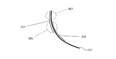
- FIG. 7 is a diagram for describing a specific example in a case where a use area on a reflection surface of a concave mirror is changed, and a design feature of the reflection surface.
- the main optical path (principal ray) of the light emitted from the light projecting unit 151 ′ is switched according to the vertical change of the viewpoint (eye point) 70.
- the area used for light reflection on the reflecting surface of the concave mirror 131 ' also changes.
- FIG. 15 shows two use areas Ze1 and Ze2.
- a region 605 where the two regions Ze1 and Ze2 overlap (a region having an overlap) 605 and a region 607 which does not overlap (a region having no overlap) are generated.
- the curvature of the reflective surface in the overlapping area 605 greatly affects the shape of the end near the virtual image display surface.
- the region Ze1 when adopted, it has a great effect on the shape of the far end of the virtual image display surface.
- the design is made with priority given to enhancing the flatness of the shape of the far end of the virtual image display surface, assuming that the region Ze1 is applied. That is, the shape of the reflection surface in the overlapping area 605 is suitable for forming the shape of the end portion (the end portion on the far side, the second end portion) of the virtual image display surface 400 remote from the vehicle 200 into a desired shape. Shape.
- FIG. 16 is a diagram illustrating a state in which a road surface is superimposed and displayed as a superimposed object (actual scene) when the vehicle is traveling on a straight road.
- the vehicle is traveling straight on a straight road with good visibility.
- a virtual image 507 for navigation is displayed (arranged) so as to overlap the road surface 80.
- the virtual image display area 305 is a square, and the side in the width direction (lateral direction) of the vehicle is longer than the side in the height direction (vertical direction) of the vehicle, and is a horizontally long rectangle.
- the convergence angle causes a phenomenon in which the virtual image is perceived as inconsistent with the road surface, or the eye point is shifted due to the fact that the viewpoint of the person is shifted in the left-right direction (see FIG. 9B).
- the possibility of occurrence of a phenomenon or the like in which the displacement appears to be enlarged due to the change in the position of the virtual image due to the movement of (1) increases. According to the above-described embodiment, it is possible to effectively cope with these positional deviations (drawing positional deviations described later).
- a specific description will be given.
- FIGS. 17A to 17C are diagrams showing how the virtual image display position changes in response to a change in the convergence angle difference and a change in the eye point in the head-up display device.
- ⁇ HUD indicates the convergence angle of both eyes (left eye 70L, right eye 70R) at the HUD focal position PC0
- ⁇ scene is the actual scene that should originally match the HUD focal position PC0.
- the convergence angle at the point PC1 of the road surface (road surface as a superimposition target) 80 is shown.
- ⁇ scene (far) is the convergence angle for the point PC2 at a greater distance from the vehicle (ie, located farther).
- a point (closer end point) P11 closest to the vehicle (or the viewer) on the virtual image display surface 400 corresponds to the imaging point PC1 in FIG. 17A. If the curvature at the end near the virtual image display surface 400 is greater, the end point P11 on the near side of the virtual image display surface 400 changes to the end point P12.
- the distance between the end point P11 and the point PC1 on the road surface 80 is D11, and this D11 indicates a distance shift.
- the distance deviation between the end point P12 and the point PC2 on the road surface 80 is D12 (> D11). In other words, if the curvature at the end near the virtual image display surface 400 is larger, the end point is further away from the road surface, and the distance shift is correspondingly increased.
- the difference between ⁇ HUD and ⁇ scene is referred to as a convergence angle difference.
- the convergence angle difference is equal to or less than (or less than) a predetermined value (threshold) ⁇ th. That is, the amount of displacement of the convergence angle caused by the shift between the virtual image forming point and the real scene (here, the road surface) corresponding to the virtual image forming point is equal to or smaller than the threshold ⁇ th (or smaller).
- a distance shift also referred to as a focus shift
- a part of the virtual image display surface 400 (the end on the far side, the center, the portion near the far end, etc.) is positioned below the road surface 80.
- the distance between the end point P11 and the road surface 80 (in other words, the lift amount of the end point P11) can be reduced. Therefore, it is possible to prevent ⁇ scene from becoming too small.
- ⁇ HUD is fixed. Therefore, it is possible to sufficiently suppress the convergence angle difference ( ⁇ HUD ⁇ scene). Therefore, a good-looking virtual image display (road surface superimposed display or the like) is realized. Specific numerical values of the threshold value ⁇ th will be described later.
- the distance between the end point P11 and the road surface 80 can be reduced. Therefore, in a HUD device having a wide viewing angle and a long virtual image display distance, for example, even when a virtual image is displayed in a wide range (a wide range extending from near to far), it is possible to display the whole without a sense of incongruity. Therefore, the reliability of the HUD device is improved.
- FIGS. 18A and 18B are diagrams for explaining the relationship between the virtual image display distance and the convergence angle difference.
- the distance between the focal position (imaging point) of the HUD device and the point on the road surface 80 corresponding to the imaging point is 1 m.
- the displacement is 1 m.
- the virtual image display distance DHUD is 5 m
- the virtual image display distance FHUD is 10 m.
- the convergence angle difference is 0.068 degrees
- the convergence angle difference is 0.034.
- the convergence angle difference is calculated with the distance between the pupils being 65 mm. If the amount of displacement is the same, the longer the virtual image display distance, the smaller the convergence angle difference. Therefore, it can be said that the problem of a decrease in the visibility of the virtual image caused by the convergence angle difference is likely to occur when the virtual image display distance is small.
- the viewpoint of the viewer of the virtual image that is the occupant of the vehicle is located at the center eye point in the left-right direction of the eye box, and the virtual image display distance A virtual image is displayed in front of 5 m or more, and the convergence angle for one point of the virtual image is defined as a first convergence angle ⁇ HUD, and the convergence angle for the point on the road surface that is the object to be superimposed corresponds to one point of the virtual image.
- the difference between the first convergence angle and the second convergence angle is the convergence angle difference
- the virtual image display distance is 5 m or more by setting the convergence angle difference to 0.068 degrees or less. In the virtual image display in the above, a decrease in visibility can be suppressed.
- the optical system includes the concave mirror (magnifying reflector), but the optical characteristic (including optical power) obtained by combining one or a plurality of optical members has an enlarging function.
- the present invention is not limited thereto, and one or more refractive optical members such as lenses, diffractive optical members such as holograms, reflective optical members, Alternatively, a combination of these may be included.
- the optical system of the present embodiment may change the optical characteristics of the optical member for each optical path through which a plurality of display lights for displaying a virtual image on each region of one or more virtual image display surfaces.
- FIG. 19 is a diagram illustrating an example of a system configuration of the head-up display device.
- the system illustrated in FIG. 19 includes a display control device 740, an object detection unit 801, a vehicle information detection unit 803, the display unit 12, a first actuator 177, and a second actuator 179.
- the display control device 740 includes an I / O interface 741, a processor 742, and a memory 743.
- the display control device 740, the object detection unit 801 and the vehicle information detection unit 803 are connected to a communication line (BUS or the like).
- the display control unit 740 can be used, for example, as the control unit 171 illustrated in FIG.
- the first actuator 177 and the second actuator 179 can be used as the rotation mechanism 179 and the adjustment unit 173 shown in FIG. 12, and individually adjust the entirety and details of the optical system 121 shown in FIG. It can also be used to do These can also be referred to as an adjustment system of the optical system.
- the object detection unit 801 can be configured by, for example, an external sensor and an external camera provided in the vehicle 2 (or 200). Further, the vehicle information detection unit 803 can be configured by, for example, a speed sensor, a vehicle ECU, an external communication device, a sensor for detecting the position of an eye, or a height sensor.
- the display control device 740 based on the detection information of the target object detection unit 801 and the information from the vehicle information detection unit 803, for example, operates the optical system optimally and performs the above-described superimposition on the road surface with a high degree of superimposition. It is also possible to realize a superimposed HUD.
- the one or more processors 742 may obtain, for example, the position of the road surface 80, and based on the position of the road surface 80, at least a part of the virtual image display surface 400 may be disposed below the road surface 80, At least one of the first and second actuators 173 and 175 can be driven.
- vehicle is to be interpreted in a broad sense, such as a vehicle (or a simulator simulating a vehicle).
- the HUD device of the present invention can be applied to an aircraft cockpit simulator and the like.
- the term road surface should be interpreted broadly, for example, as a reference surface.
Abstract
The purpose of the present invention to provide is a head-up display device capable of stably displaying a virtual image which can be visually recognized on a road surface when a vehicle drives. A head-up display device (101) according to the present invention comprises a display means that projects display light (50) on a reflection/transmission member (300) installed in a vehicle (200) and generates and displays a virtual image by the display light (50) reflected in the reflection/transmission member (300) so as to overlap a real view transmitting the reflection/transmission member (300). A virtual image displaying surface (400) on which virtual images are to be displayed is disposed such that an end (403) on the farther side from the vehicle should be lower than an end (406) on the nearer side to the vehicle.
Description
本発明は、車両のフロントウインドシールドやコンバイナ等に虚像を表示するヘッドアップディスプレイ装置に関する。
The present invention relates to a head-up display device that displays a virtual image on a front windshield, a combiner, or the like of a vehicle.
車両のフロントウインドシールドやコンバイナ等の反射透光部材を透過する実景(車両前方の風景)に重ねて、その反射透光部材に反射された表示光により虚像を生成して表示するヘッドアップディスプレイ装置は、車両を運転する視認者の視線移動を極力抑えつつ、視認者が所望する情報を虚像により提供することによって、安全で快適な車両運行に寄与する。
A head-up display device that superimposes on a real scene (a scene in front of the vehicle) that passes through a reflective translucent member such as a front windshield or a combiner of a vehicle and generates and displays a virtual image with display light reflected by the reflective translucent member. Contributes to safe and comfortable vehicle operation by providing the information desired by the viewer with a virtual image while minimizing the line of sight movement of the viewer driving the vehicle.
例えば特許文献1に記載のヘッドアップディスプレイ装置は、車両のダッシュボードに設けられてフロントウインドシールドに表示光を投影し、フロントウインドシールドで反射された表示光により視認者に虚像表示面上の虚像を視認させる。同特許文献では、車両が進行する路面と略平行な第一の虚像表示面上にある第一の虚像と、車両の進行方向と垂直な方向に略平行な第二の虚像表示面上にある第二の虚像とが、所定の角度をなすように表示される。
For example, a head-up display device described in Patent Document 1 is provided on a dashboard of a vehicle, projects display light on a front windshield, and gives a viewer a virtual image on a virtual image display surface by the display light reflected by the front windshield. Is visually recognized. In this patent document, the first virtual image is on a first virtual image display surface substantially parallel to the road surface on which the vehicle travels, and is on the second virtual image display surface substantially parallel to the direction perpendicular to the traveling direction of the vehicle. The second virtual image is displayed so as to form a predetermined angle.
ところで、特許文献1において、第一の虚像は路面の所定の範囲に亘って重畳して視認されるが、第一の虚像表示面が路面の上方に位置しているため(同特許文献の段落0015、図1参照)、視認者には、第一の虚像が路面から浮いているように視認される。同特許文献における第一の虚像のように、車両の経路を示す矢印等の虚像は、路面から浮いているように視認されるのではなく、路面に張り付いて視認される方が望ましい場合がある。
By the way, in Patent Literature 1, the first virtual image is visually recognized in a superimposed manner over a predetermined range of the road surface. However, since the first virtual image display surface is located above the road surface (see paragraphs in the same patent document). 0015, FIG. 1), the viewer sees the first virtual image as if it were floating above the road surface. Like the first virtual image in the patent document, virtual images such as arrows indicating the route of the vehicle may not be visually recognized as floating from the road surface, but may be desirable to be viewed by sticking to the road surface. is there.
しかしながら、そのために図8(a)に示すように虚像表示面40を路面41の上方ではなく路面41と同じ高さに位置させると、車両42の走行中、路面41が平坦でなかったり、車両42の姿勢変化(ピッチ角の変化)があったりした場合に、同図(b)に示すように虚像表示面40が路面41の上方に浮いて虚像43が路面41から浮き上がることになり、虚像43が路面41に調和していないとの違和感を視認者44が覚えやすいという問題があった。
However, if the virtual image display surface 40 is positioned not above the road surface 41 but at the same height as the road surface 41 as shown in FIG. 8A, the road surface 41 is not If there is a change in the posture (change in the pitch angle) at 42, the virtual image display surface 40 floats above the road surface 41 and the virtual image 43 rises from the road surface 41 as shown in FIG. There was a problem that the viewer 44 could easily remember the uncomfortable feeling that 43 was not in harmony with the road surface 41.
本発明は、上記の事情に鑑みてなされたもので、路面に張り付いて視認される虚像を車両の走行時に安定して表示することができるヘッドアップディスプレイ装置を提供することを課題としている。
The present invention has been made in view of the above circumstances, and it is an object of the present invention to provide a head-up display device capable of stably displaying a virtual image stuck on a road surface when a vehicle is running.
本発明のヘッドアップディスプレイ装置の一態様では、車両に設けられた反射透光部材に表示光を投影し、前記反射透光部材を透過する実景に重ねて前記反射透光部材に反射された表示光により虚像を生成して表示する表示手段を備えるヘッドアップディスプレイ装置であって、画像を表示する表示面を有する画像表示部と、前記表示光を、前記反射透光部材部材に投影する光学部材を含む光学系と、を有し、前記ヘッドアップディスプレイは、前記虚像を表示する虚像表示面を有し、前記虚像表示面は、前記車両から近い側の第1の端部と、遠い側の第2の端部を有し、前記第2の端部が、前記第1の端部より低く配置される。
また、前記第1の端部が、前記虚像表示面のうち、最高位置に配置されてもよい。
また、前記虚像表示面が、前記路面より下になる部分を有さない場合には、前記虚像表示面は、前記第1の端部が前記路面よりも上に位置する曲面であり、前記第1の端部における前記車両に最も近い端点の前記路面からの距離が、前記虚像表示面の内で最大となり、かつ、前記第2の端部の少なくとも一部が、前記路面に重なるように、前記第1の端部よりも平坦性が高められた面とされた形状を有し、前記光学系における全領域又は一部の領域の光学的特性を調整すること、前記光学部材と前記表示面との配置を調整すること、前記表示面の形状を調整すること、又はこれらの組み合わせにより、前記虚像表示面の形状を形成してもよい。
また、前記虚像表示面は、前記第2の端部を含む一部又はその全部が前記路面下に位置してもよい。
また、前記虚像表示面は、前記路面と前記第2の端部との距離が、前記路面と前記第1の端部との距離より長くなるように配置されてもよい。
また、前記第1、第2の端部が、前記路面より上に位置してもよい。
また、前記光学部材は、曲面の反射面を有する凹面鏡を有し、前記凹面鏡における前記曲面の反射面の形状が、前記虚像表示面の形状を生じさせるべく調整されていてもよい。
また、前記車両の幅に沿う方向を左右方向という場合に、前記車両の搭乗者である前記虚像の視認者の視点が、アイボックスの、左右方向における中央のアイポイントに位置し、かつ、虚像表示距離が5m以上の前方に虚像が表示され、かつ、前記虚像の一点についての輻輳角を第1の輻輳角とし、前記虚像の一点に対応する、重畳対象物である前記路面上の点についての輻輳角を第2の輻輳角とし、前記第1の輻輳角と前記第2の輻輳角との差を輻輳角差とするとき、前記輻輳角差が、0.068度以下であってもよい。
また、前記表示面又は/及び前記光学部材を移動又は/及び回転させるように構成される1つ又はそれ以上のアクチュエータと、1つ又はそれ以上のI/Oインタフェースと、1つ又はそれ以上のプロセッサと、メモリと、前記メモリに格納され、前記1つ又はそれ以上のプロセッサによって実行されるように構成される1つ又はそれ以上のコンピュータ・プログラムと、をさらに備え、前記1つ又はそれ以上のプロセッサは、前記路面の位置を取得し、前記路面の位置に基づき、前記虚像表示面の少なくとも一部が、前記路面下に配置するように、前記アクチュエータを駆動してもよい。
また、前記光学部材の反射面は、前記車両に搭乗する視認者のアイポイントが第1の位置にあるときの第1の使用領域と、前記第1の位置とは、上下方向における位置が異なる第2の位置にあるときの第2の使用領域と、を有し、前記第1、第2の各使用領域が重複する領域における前記反射面の形状は、前記虚像表示面における、前記車両から遠い側の前記第2の端部の形状を所望形状に形成するのに適した形状とされてもよい。 In one aspect of the head-up display device of the present invention, the display light is projected on a reflective translucent member provided in a vehicle, and a display reflected by the reflective translucent member is superimposed on an actual scene transmitted through the reflective translucent member. A head-up display device including a display unit that generates and displays a virtual image with light, an image display unit having a display surface that displays an image, and an optical member that projects the display light onto the reflective translucent member member Wherein the head-up display has a virtual image display surface that displays the virtual image, and the virtual image display surface has a first end closer to the vehicle and a remote end closer to the vehicle. A second end, wherein the second end is located lower than the first end;
Further, the first end may be arranged at a highest position on the virtual image display surface.
Further, when the virtual image display surface does not have a portion below the road surface, the virtual image display surface is a curved surface where the first end is located above the road surface, and The distance from the road surface of the end point closest to the vehicle at one end is the largest in the virtual image display surface, and at least a part of the second end portion overlaps the road surface, Adjusting the optical characteristics of the entire area or a partial area of the optical system, wherein the optical member and the display surface have a flattened shape higher than the first end; The shape of the virtual image display surface may be formed by adjusting the arrangement of the virtual image display surface, adjusting the shape of the display surface, or a combination thereof.
Also, the virtual image display surface may be partially or entirely including the second end portion located below the road surface.
In addition, the virtual image display surface may be arranged such that a distance between the road surface and the second end is longer than a distance between the road surface and the first end.
Further, the first and second ends may be located above the road surface.
Further, the optical member may include a concave mirror having a curved reflecting surface, and a shape of the curved reflecting surface of the concave mirror may be adjusted to cause a shape of the virtual image display surface.
Further, when a direction along the width of the vehicle is referred to as a left-right direction, a viewpoint of a viewer of the virtual image which is a passenger of the vehicle is located at a central eye point in the left-right direction of the eye box, and A virtual image is displayed in front of the display distance of 5 m or more, and a convergence angle for one point of the virtual image is defined as a first convergence angle, and a point on the road surface, which is an object to be superimposed, corresponding to one point of the virtual image. When the convergence angle of the second convergence angle and the difference between the first convergence angle and the second convergence angle is the convergence angle difference, even if the convergence angle difference is 0.068 degrees or less Good.
Also, one or more actuators configured to move or / and rotate the display surface or / and the optical member, one or more I / O interfaces, and one or more A processor, a memory, and one or more computer programs stored in the memory and configured to be executed by the one or more processors; May obtain the position of the road surface, and may drive the actuator based on the position of the road surface such that at least a part of the virtual image display surface is disposed below the road surface.
Further, the reflection surface of the optical member has a first use area when an eye point of a viewer riding the vehicle is at a first position, and a position in the vertical direction is different from the first position. And a second use area when in the second position, wherein the shape of the reflection surface in an area where the first and second use areas overlap is from the vehicle on the virtual image display surface. The shape of the second end on the far side may be a shape suitable for forming a desired shape.
これにより、例えば、虚像の全体を路面に近づけて配置することができる。言い換えれば、路面重畳HUDにおいて、虚像の路面からの浮き上がりを抑制することができる。また、例えば、虚像の遠方に位置する部分(遠方部分であり、先端部分ということもできる)は、車両の運転者等(虚像の視認者)にとって重要な情報をもつ場合が多い。よって、その遠方部分を、平坦性を高くして路面により近づけて重畳するように調整することによって、運転者等の視認性や認知性を高めることができる。
Thereby, for example, the entire virtual image can be arranged close to the road surface. In other words, in the road surface superposition HUD, it is possible to suppress the virtual image from rising off the road surface. Further, for example, a portion located far from the virtual image (a distant portion, which can also be referred to as a tip portion) often has important information for a driver of the vehicle or the like (a viewer of the virtual image). Therefore, by adjusting the distant portion so that the flatness is increased so as to be closer to the road surface so as to overlap the road surface, visibility and recognition of the driver and the like can be improved.
また、虚像の一部が路面の下(但し、路面の垂線に沿う方向を上下方向とする。よって、例えば、路面が水平なら鉛直下向きが下方向となる)に位置する場合であっても、虚像の遠方部分の路面への重畳性は維持しつつ、近傍の浮いた表示を、なるべく路面に近づけることができる。よって、近傍での路面重畳性を確保することもできる。
In addition, even if a part of the virtual image is located below the road surface (however, the direction along the vertical line of the road surface is the up-down direction, for example, if the road surface is horizontal, the vertical downward direction is the downward direction), While maintaining the superimposition of the distant portion of the virtual image on the road surface, the nearby floating display can be brought as close as possible to the road surface. Therefore, the road surface superimposition property in the vicinity can be ensured.
上記のような本発明の実施態様によれば、路面に重畳される虚像の、路面からの浮き上がりを効果的に抑制することができる。このことは、広画角、かつ虚像表示距離が長いHUD装置の視認性向上に貢献する。
According to the embodiment of the present invention as described above, it is possible to effectively suppress the floating of the virtual image superimposed on the road surface from the road surface. This contributes to improving the visibility of the HUD device having a wide angle of view and a long virtual image display distance.
本発明に係るヘッドアップディスプレイ装置によれば、路面に張り付いて視認される虚像を車両の走行時に安定して表示することができる。
According to the head-up display device of the present invention, it is possible to stably display a virtual image stuck on a road surface when the vehicle is running.
本発明を実施するための形態について、図面に基づいて説明する。
An embodiment for carrying out the present invention will be described with reference to the drawings.
図1に示すように、本実施の形態に係るヘッドアップディスプレイ装置(HUD)1は、車両2のフロントウインドシールド3の下方に位置するダッシュボード4の内部に設けられ、フロントウインドシールド3の一部に表示光5を投影する。表示光5は、フロントウインドシールド3に反射されて虚像6を生成し、視認者(運転者)7にフロントウインドシールド3を透過する実景に重ねて虚像6を視認させる。虚像6は、後に詳述するように、車両2が進行する路面8の下方に位置する虚像表示面9に表示される。
As shown in FIG. 1, a head-up display device (HUD) 1 according to the present embodiment is provided inside a dashboard 4 located below a front windshield 3 of a vehicle 2, The display light 5 is projected onto the section. The display light 5 is reflected by the front windshield 3 to generate a virtual image 6, and allows a viewer (driver) 7 to visually recognize the virtual image 6 so as to be superimposed on an actual scene transmitted through the front windshield 3. The virtual image 6 is displayed on a virtual image display surface 9 located below a road surface 8 on which the vehicle 2 travels, as described later in detail.
HUD1は、図2に示すように、透光部10が形成されたケース11の内部に表示部12、反射鏡13及び画像生成部14が設けられて概略構成されている。表示部12は、DMDやLCoS等の反射型表示デバイスを用いたプロジェクタからなる投影部15と、投影部15からの投影光を受光し、画像を含む表示光5を反射鏡13に向けて出射するスクリーン16とを備える。表示部12からの表示光5は、凹状の反射鏡13に反射され、透光部10を透過してフロントウインドシールド3に投影される。フロントウインドシールド3に投影された表示光5は、視認者7の側に反射され、虚像6を生成して視認者7に表示する(図1参照)。なお、反射鏡13は、図示を略す駆動機構により回動駆動されることによって、表示光5のフロントウインドシールド3における投影位置を変更可能としてもよく、投影部15は、LED照明とTFT液晶との組合せ等により構成してもよい。
As shown in FIG. 2, the HUD 1 is schematically configured such that a display unit 12, a reflecting mirror 13, and an image generation unit 14 are provided inside a case 11 in which a light transmitting unit 10 is formed. The display unit 12 includes a projection unit 15 including a projector using a reflective display device such as DMD or LCoS, and receives projection light from the projection unit 15 and emits display light 5 including an image to the reflection mirror 13. And a screen 16 for performing the operation. The display light 5 from the display unit 12 is reflected by the concave reflecting mirror 13, passes through the light transmitting unit 10, and is projected on the front windshield 3. The display light 5 projected on the front windshield 3 is reflected to the viewer 7 side, generates a virtual image 6 and displays it on the viewer 7 (see FIG. 1). The reflecting mirror 13 may be capable of changing a projection position of the display light 5 on the front windshield 3 by being rotationally driven by a driving mechanism (not shown). And the like.
画像生成部14は、マイコンやGDC等からなり、図3に示すように、表示部12及びCAN等の車内LANのバス27に接続されている。バス27には、カメラ、LiDAR又はV2X等により車両2が進行する路面8その他の車両周囲の対象物を検出する対象物検出部16や、CANトランシーバIC、GNSS、加速度センサ、モーションセンサ、ジャイロセンサ等により車速、加速度その他の車両情報を検出する車両情報検出部17が接続されている。
The image generation unit 14 includes a microcomputer, a GDC, and the like, and is connected to the display unit 12 and an in-vehicle LAN bus 27 such as a CAN, as shown in FIG. The bus 27 includes an object detection unit 16 that detects a road surface 8 on which the vehicle 2 travels and other objects around the vehicle by a camera, LiDAR, V2X, or the like, a CAN transceiver IC, a GNSS, an acceleration sensor, a motion sensor, and a gyro sensor. A vehicle information detecting unit 17 for detecting vehicle speed, acceleration, and other vehicle information is connected to the vehicle.
表示光5により生成される虚像6は、車両2が進行する路面8に張り付いて視認されるもので、図4(a)に示すフロントウインドシールド3の表示領域18に表示されるナビゲーションの矢印19や、同図(b)に示す先行車(先行車は、視認者7に実景として視認される。)との車間距離を表すガイド20等を含んでいてもよい。ここでは、画像生成部14が、虚像表示面9が路面8に対して概ね平行となるように、かつ、路面8の下方に位置するように表示光5を投影し(図1参照)、虚像表示面9は、車両2から所定距離(20~50m)だけ遠方(前方)の路面8において、所定深さ(路面8の下方50~200cm)に位置している。
The virtual image 6 generated by the display light 5 is attached to the road surface 8 on which the vehicle 2 travels and is visually recognized, and is a navigation arrow displayed in the display area 18 of the front windshield 3 shown in FIG. 19 and a guide 20 indicating the distance between the vehicle and a preceding vehicle (the preceding vehicle is visually recognized by the viewer 7 as a real scene) shown in FIG. Here, the image generation unit 14 projects the display light 5 so that the virtual image display surface 9 is substantially parallel to the road surface 8 and is positioned below the road surface 8 (see FIG. 1), and the virtual image is displayed. The display surface 9 is located at a predetermined depth (50 to 200 cm below the road surface 8) on the road surface 8 that is far (forward) from the vehicle 2 by a predetermined distance (20 to 50 m).
また、画像生成部14は、図5に示すように、車両2に対する虚像表示面9の位置を一定となるように(上記所定距離及び/又は上記所定深さが維持されるように)調整する。すなわち、画像生成部14は、車両情報検出部17(加速度センサ、モーションセンサ、ジャイロセンサ等)の検出結果から車両のピッチ角を取得し(ステップ1(図5において「S.1」と記載。以下同様。))、そのピッチ角と上記所定距離及び/又は上記所定深さに基づいて、虚像表示面9の所望の表示位置(図6(a))と取得したピッチ角の分ずれた表示位置(図6(b))とのずれ量を算出する(ステップ2)。そして、そのずれ量を打ち消すように、車両2に対する虚像表示面9の位置を調整し(ステップ3)、調整後の虚像表示面9に対応する表示光5を投影するように表示部12を制御する(ステップ4)。
Further, as shown in FIG. 5, the image generating unit 14 adjusts the position of the virtual image display surface 9 with respect to the vehicle 2 so that the predetermined distance and / or the predetermined depth is maintained. . That is, the image generation unit 14 acquires the pitch angle of the vehicle from the detection result of the vehicle information detection unit 17 (acceleration sensor, motion sensor, gyro sensor, etc.) (Step 1 (described as “S.1” in FIG. 5). Based on the pitch angle and the predetermined distance and / or the predetermined depth, a display shifted from the desired display position (FIG. 6A) on the virtual image display surface 9 by the acquired pitch angle is performed. The amount of deviation from the position (FIG. 6B) is calculated (step 2). Then, the position of the virtual image display surface 9 with respect to the vehicle 2 is adjusted so as to cancel the shift amount (Step 3), and the display unit 12 is controlled to project the display light 5 corresponding to the virtual image display surface 9 after the adjustment. (Step 4).
なお、図5においては、画像生成部14が現に生じたピッチ角の変化に応じて虚像表示面9の位置を調整しているが、対象物検出部16(カメラ、LiDAR等)により路面8の形状や凹凸等を検出してその検出結果も勘案し、次の瞬間のピッチ角を推定して虚像表示面9の位置を調整することによって、リアルタイム性を向上させてもよい。
In FIG. 5, the position of the virtual image display surface 9 is adjusted according to the change in the pitch angle actually generated by the image generation unit 14. However, the object detection unit 16 (camera, LiDAR, or the like) adjusts the road surface 8. The real-time property may be improved by detecting the shape, unevenness, and the like, taking into account the detection results, and estimating the pitch angle at the next moment to adjust the position of the virtual image display surface 9.
さらに、虚像表示面9を路面8の下方に位置させるために、画像生成部14は、対象物検出部16により路面8を検出したり、あるいは、車両2が接地する路面の高さと同一とみなしたりすることによって、路面8の高さを把握する。
Further, in order to position the virtual image display surface 9 below the road surface 8, the image generation unit 14 detects the road surface 8 by the object detection unit 16 or assumes that the height is the same as the height of the road surface on which the vehicle 2 touches the ground. To grasp the height of the road surface 8.
本実施の形態に係るHUD1では、虚像表示面9が、車両2が進行する路面8の下方に位置し、虚像6も路面8の下方に表示されるが、虚像6は、視認者7には、路面8にそれ以上奥側がないという先入観から、路面8に張り付いているように視認され、この傾向は、特に虚像表示面9及び虚像6が車両2から遠方に位置するほど、視認者7の奥行知覚が鈍感になり顕著となる。つまり、実際には、視認者7から見て、虚像6は路面8の奥側(下方)で結像しているにもかかわらず、視認者7は、あたかも路面8の表面に虚像6が張り付いて表示されているかのように知覚する。
In the HUD 1 according to the present embodiment, the virtual image display surface 9 is located below the road surface 8 on which the vehicle 2 travels, and the virtual image 6 is also displayed below the road surface 8. From the prejudice that the road surface 8 has no further depth side, it is visually recognized that the road surface 8 is stuck to the road surface 8. This tendency is particularly noticeable as the virtual image display surface 9 and the virtual image 6 are located farther from the vehicle 2. Depth perception becomes insensitive and remarkable. That is, although the virtual image 6 is actually formed on the far side (below) of the road surface 8 when viewed from the viewer 7, the viewer 7 feels as if the virtual image 6 is stretched on the surface of the road surface 8. Perceive as if it were displayed.
また、仮に、画像生成部14による虚像表示面9の位置調整機能がない場合に車両2のピッチ角が変化した際や、その位置調整機能の想定を超えて車両2のピッチ角が変化した際に、虚像表示面9が図6(a)から(b)に示すように浮き上がったとしても、路面8の下方に位置していた虚像表示面9は、浮き上がってもなお路面8の下方に位置し、視認者7にとって虚像6は路面8に張り付いたままに見え、路面8との重畳感が失われない。
Further, if the pitch angle of the vehicle 2 changes when there is no function of adjusting the position of the virtual image display surface 9 by the image generation unit 14, or when the pitch angle of the vehicle 2 changes beyond the assumption of the position adjustment function In addition, even if the virtual image display surface 9 rises as shown in FIGS. 6A and 6B, the virtual image display surface 9 that has been positioned below the road surface 8 is still positioned below the road surface 8 even if it has floated. However, the virtual image 6 appears to the viewer 7 as sticking to the road surface 8, and the sense of overlap with the road surface 8 is not lost.
したがって、HUD1によれば、路面8に張り付いて視認される虚像6を、車両2の走行中に車両2のピッチ角や路面8の形状、凹凸が変化したとしても、安定して表示することができる。ここでは、画像生成部14が車両2に対する虚像表示面9の位置を一定となるように調整し、虚像表示面9が路面8から浮き上がること自体が抑制されるとともに、視認者7から見て虚像6が一定の場所に表示されるので、虚像6は、車両2の走行時に、より一層安定的に路面8に張り付いたように表示され、その視認性も向上している。
Therefore, according to the HUD 1, it is possible to stably display the virtual image 6 sticking to the road surface 8 even if the pitch angle of the vehicle 2, the shape of the road surface 8, or the unevenness of the vehicle 2 changes while the vehicle 2 is running. Can be. Here, the image generation unit 14 adjusts the position of the virtual image display surface 9 with respect to the vehicle 2 so as to be constant, so that the virtual image display surface 9 itself is prevented from rising from the road surface 8 and the virtual image viewed from the viewer 7. Since the virtual image 6 is displayed at a fixed location, the virtual image 6 is displayed more stably on the road surface 8 when the vehicle 2 is traveling, and the visibility is improved.
図7は、本実施の形態に係る他のHUD21が設けられた車両2を示す。HUD21は、画像生成部の生成画像が異なるほかは、HUD1と同様の構成を有するので、各部の詳細な説明は省略する。
FIG. 7 shows a vehicle 2 provided with another HUD 21 according to the present embodiment. The HUD 21 has the same configuration as the HUD 1 except that the image generated by the image generation unit is different, and thus a detailed description of each unit is omitted.
HUD21による虚像表示面22は、車両2に対する遠方側(視認者7から見て上側)の端部23が、近傍側(視認者7から見て下側)の端部24よりも上方に位置し、さらには、路面8の上方に位置する。また、車両2に対する近傍側の端部24が路面8の下方に位置し、虚像表示面22の路面8よりも上方の部分には、路面8上の背景に重畳される背景関連虚像(車速やナビゲーションによる次の案内地点までの残距離、FCW(前方衝突警報)等についての像)25が表示され、路面8よりも下方の部分には、路面8に重畳されて路面8に張り付いたように視認される路面関連虚像26が表示される。
In the virtual image display surface 22 formed by the HUD 21, the end 23 on the far side (upper side as viewed from the viewer 7) with respect to the vehicle 2 is positioned higher than the end 24 on the near side (lower side as viewed from the viewer 7). And above the road surface 8. In addition, an end 24 on the near side to the vehicle 2 is located below the road surface 8, and a portion of the virtual image display surface 22 above the road surface 8 includes a background-related virtual image (vehicle speed or The remaining distance to the next guidance point by the navigation, an image of FCW (forward collision warning) 25, etc.) are displayed, and a portion below the road surface 8 is superimposed on the road surface 8 so as to stick to the road surface 8. The road surface related virtual image 26 visually recognized is displayed.
HUD21では、虚像表示面22の遠方側の端部23が路面8の上方に位置し、近傍側の端部24が路面8の下方に位置しているので、虚像6と同様に路面8に張り付いて視認される路面関連虚像26を端部23の側に表示しつつ、路面8上の背景に重畳される背景関連虚像25を端部24の側に表示することができる。
In the HUD 21, the far end 23 of the virtual image display surface 22 is located above the road surface 8, and the near end 24 is located below the road surface 8. The road-related virtual image 26 superimposed on the background on the road surface 8 can be displayed on the side of the end 24 while the road-related virtual image 26 that is visually recognized is displayed on the side of the end 23.
以上、本発明を実施するための形態について例示したが、本発明の実施形態は上述したものに限られず、発明の趣旨を逸脱しない範囲で適宜変更等してもよい。
Although the embodiments for carrying out the present invention have been described above, the embodiments of the present invention are not limited to those described above, and may be appropriately changed without departing from the spirit of the invention.
例えば、HUDは、虚像表示面の少なくとも一部を車両が進行する路面の下方に位置させることができるのであれば、表示部その他各部の構成は任意である。
For example, the configuration of the display unit and other components of the HUD is arbitrary as long as at least a part of the virtual image display surface can be positioned below the road surface on which the vehicle travels.
また、虚像表示面の表示位置及び虚像の表示内容も任意であり、虚像表示面が路面となす角度についても、虚像表示面9のように路面8と略平行でも、虚像表示面22のように路面8と略垂直でも、その他の角度でもかまわない。
The display position of the virtual image display surface and the display content of the virtual image are also arbitrary. Regarding the angle formed by the virtual image display surface and the road surface, even if the virtual image display surface is substantially parallel to the road surface 8 as in the virtual image display surface 9, as in the virtual image display surface 22. It may be substantially perpendicular to the road surface 8 or another angle.
虚像が路面に張り付いているように見える視覚的な程度(虚像の路面との重畳感、一体感)をより高めるためには、虚像表示面は全体的に寝た状態(路面と平行に近い状態)で路面の近くにあることが望ましいが、車両から虚像表示面までの距離が上記所定距離(20~50m)で、路面から虚像表示面までの深さが上記所定深さ(50~200cm)程度であれば、虚像は十分に路面に張り付いているように視認され、しかも、車両の通常の走行状況下において、車両のピッチ角の変化や路面の形状、凹凸の変化により路面から浮き上がって見えることも防止される。
In order to further increase the visual degree (a sense of superimposition of the virtual image on the road surface, a sense of unity) that the virtual image appears to be stuck to the road surface, the virtual image display surface is generally in a lying state (close to being parallel to the road surface). It is desirable that the distance from the vehicle to the virtual image display surface is the predetermined distance (20 to 50 m) and the depth from the road surface to the virtual image display surface is the predetermined depth (50 to 200 cm). ), The virtual image is visually recognized as being sufficiently stuck to the road surface, and rises from the road surface due to a change in the pitch angle of the vehicle, a change in the shape of the road surface, or a change in the unevenness of the vehicle under normal driving conditions of the vehicle. It is also prevented from seeing.
次に、図9を参照する。図9(a)はヘッドアップディスプレイ装置の倍率、焦点を説明するための図、図9(b)は視認者のアイポイントと虚像位置との関係について説明するための図である。
Next, FIG. 9 is referred to. FIG. 9A is a diagram for explaining a magnification and a focus of the head-up display device, and FIG. 9B is a diagram for explaining a relationship between an eye point of a viewer and a virtual image position.
図9(a)に示されるように、画像表示部(表示器や、透過型又は反射型のスクリーン等)Sの表示面から、反射透光部材(ウインドシールドやコンバイナ等)Tまでの距離を光路長aとし、人(視認者)の視点E(あるいは、車両の所定箇所)から虚像V(あるいは虚像表示面の基準点)までの距離を虚像表示距離bとする。このとき、a<bであれば、拡大表示がなされ、倍率Kはb/aで表される。また、焦点距離をfとするとき、1/f=1/a-1/bが成立する。
As shown in FIG. 9A, the distance from the display surface of the image display unit (display, transmissive or reflective screen, etc.) S to the reflective translucent member (wind shield, combiner, etc.) T is set. An optical path length a is defined as a distance from a viewpoint E (or a predetermined position of the vehicle) of a person (viewer) to a virtual image V (or a reference point on the virtual image display surface) is defined as a virtual image display distance b. At this time, if a <b, the display is enlarged and the magnification K is represented by b / a. When the focal length is f, 1 / f = 1 / a-1 / b holds.
近年、視野角が大きく(例えば視認者から見た縦方向の有効視野が10度程度)、かつ、虚像表示距離bが長い(例えば7m以上)のHUD装置が求められている。視野角及び虚像表示距離を共に増大させようとすると、HUD装置の大型化を招く。大型化を抑制するためには、光路長(上記のa)の増大を抑制しつつ、HUD装置の光学系の倍率(光学倍率)を大きくしなければならない。光学倍率を大きくするには、例えば、凹面鏡や補正鏡等の光学部材の曲面を大きく湾曲させる必要がある。また、HUD装置の高画角化に伴い、画像表示部の表示面のサイズが大型化し、凹面鏡等の光学部材も大型化し、凹面鏡の大きく湾曲した周辺領域にも表示光が当たるようになる。よって、例えば、平坦な路面を重畳対象物として、その路面上に、ナビゲーション表示(平坦面をもつ矢印等)を重ねて表示するような場合に、そのナビゲーション表示(虚像)を、完全には平坦な表示とすることができない。言い換えれば、そのナビゲーション表示(虚像)を、全画角にわたって完全な平坦性を確保しつつ、路面上に重畳表示することは困難である。
In recent years, there has been a demand for a HUD device having a large viewing angle (for example, an effective visual field in the vertical direction viewed from a viewer of about 10 degrees) and a long virtual image display distance b (for example, 7 m or more). Attempts to increase both the viewing angle and the virtual image display distance lead to an increase in the size of the HUD device. In order to suppress an increase in size, it is necessary to increase the magnification (optical magnification) of the optical system of the HUD device while suppressing an increase in the optical path length (a). In order to increase the optical magnification, for example, it is necessary to greatly curve a curved surface of an optical member such as a concave mirror or a correction mirror. In addition, as the angle of view of the HUD device increases, the size of the display surface of the image display unit increases, the size of optical members such as a concave mirror also increases, and the display light shines on the largely curved peripheral region of the concave mirror. Therefore, for example, when a flat road surface is set as an object to be superimposed and a navigation display (an arrow having a flat surface or the like) is superimposed and displayed on the road surface, the navigation display (virtual image) is completely flat. Cannot be displayed properly. In other words, it is difficult to superimpose the navigation display (virtual image) on the road surface while ensuring complete flatness over the entire angle of view.
また、図9(b)では、画像Mが画像表示部Sの表示面に表示され、凹面鏡WD、フロントシールド(反射透光部材)Tを介して虚像の表示がなされている。図9(b)では、視認者(車両の運転者等)のアイポイントEP(C)は、アイボックスEBの中央に位置する。左右の各目に対応する虚像表示面をPLN(L)、PLN(R)とすると、その重なりの領域の中央に虚像V(C)が位置する。虚像V(C)が、対象物に重畳される場合、虚像V(C)についての輻輳角と、重畳対象物の輻輳角との差の程度が大きくなると、焦点ずれが顕在化して、視認者は違和感を覚える(この点は後述する)。
9 (b), the image M is displayed on the display surface of the image display unit S, and a virtual image is displayed via the concave mirror WD and the front shield (reflective translucent member) T. In FIG. 9B, the eye point EP (C) of the viewer (the driver of the vehicle or the like) is located at the center of the eye box EB. Assuming that the virtual image display surfaces corresponding to the left and right eyes are PLN (L) and PLN (R), the virtual image V (C) is located at the center of the overlapping area. When the virtual image V (C) is superimposed on the object, if the degree of difference between the convergence angle of the virtual image V (C) and the convergence angle of the superimposed object increases, the defocus becomes apparent and the viewer Is uncomfortable (this point will be described later).
また、視認者のアイポイントが、車両の幅方向(左右方向)に沿って移動すると(EP(L)、EP(R))、画像Mの表示位置に変更がなくても、虚像の表示位置が変化する。広視野角の表示が可能なHUD装置では、そのアイポイントの移動距離も大きくなり、虚像の左右方向の位置ずれ(言い換えれば、描画位置ずれ)が増大して、この場合も、視認者は違和感を覚えることになる(この点も後述する)。したがって、焦点ずれや描画位置ずれを、適切に抑制することも重要である。
Also, when the eye point of the viewer moves along the width direction (left-right direction) of the vehicle (EP (L), EP (R)), even if the display position of the image M is not changed, the display position of the virtual image is changed. Changes. In a HUD device capable of displaying a wide viewing angle, the moving distance of the eye point is also large, and the lateral displacement of the virtual image (in other words, the displacement of the drawing position) is increased. (This point will also be described later). Therefore, it is also important to appropriately suppress the focus shift and the drawing position shift.
従来、上述の、虚像Vの歪みに対する対策としては、歪みをできるだけ抑制する、言い換えれば、歪みを補正する、という考え方が主流であった。これに対して、本発明の実施形態では、歪みを補正するのではなく、人の視覚を通じた像の知覚の特性を考慮しつつ、凹面鏡の曲面形状等を調整し、像の歪みを適正に、精度よく制御し、その像の歪みを目立たなくする、という、新たな手法を導入する。これにより、路面に虚像を重畳する際の、路面からの虚像の浮き上がり等を、比較的容易に抑制することが可能となる。
Conventionally, as a countermeasure against the above-described distortion of the virtual image V, the idea of suppressing the distortion as much as possible, in other words, correcting the distortion has been the mainstream. In contrast, in the embodiment of the present invention, instead of correcting the distortion, the curved surface shape and the like of the concave mirror are adjusted while considering the characteristics of the perception of the image through human vision, and the distortion of the image is appropriately adjusted. Introducing a new method of controlling the accuracy and making the image distortion less noticeable. This makes it possible to relatively easily suppress the floating of the virtual image from the road surface when the virtual image is superimposed on the road surface.
以下、具体的に説明する。図10を参照する。図10(a)はヘッドアップディスプレイ装置の他の例による、虚像表示面を用いた虚像表示を示す図、図10(b)画像表示部の表示面に表示される画像の例を示す図である。なお、図10(a)において、車両200の前方に沿う方向(前後方向ともいう)をZ方向とし、車両200の幅(横幅)に沿う方向(左右方向)をX方向とし、車両200の高さ方向(平坦な路面80に垂直な線分の、路面80から離れる方向)をY方向とする。
す る The following is a specific description. Please refer to FIG. FIG. 10A is a diagram illustrating a virtual image display using a virtual image display surface according to another example of the head-up display device, and FIG. 10B is a diagram illustrating an example of an image displayed on the display surface of the image display unit. is there. In FIG. 10A, the direction along the front of the vehicle 200 (also referred to as the front-back direction) is defined as the Z direction, the direction along the width (lateral width) of the vehicle 200 is defined as the X direction, and the height of the vehicle 200 is defined as the X direction. The vertical direction (the direction perpendicular to the flat road surface 80 and away from the road surface 80) is defined as the Y direction.
また、以下の説明では、虚像表示面400の形状の説明等において、上、下、という表現をする。ここでは、説明の便宜上、路面80に垂直な線分(法線)に沿う方向を上下方向とする。路面が水平である場合は、鉛直下向きが下方であり、その反対方向が上方である。
In the following description, the terms “up” and “down” will be used in the description of the shape of the virtual image display surface 400 and the like. Here, for convenience of description, a direction along a line segment (normal line) perpendicular to the road surface 80 is defined as an up-down direction. When the road surface is horizontal, the vertical downward direction is downward, and the opposite direction is upward.
図10(a)の上側に示されるように、車両(自車両)200は、直線状に延びる路面(道路)80上を走行している。本実施形態のHUD装置101の画像表示領域303には、路面80の延在方向と一致する方向に、直線状に延びる延在部分(延在成分)を有する虚像である、矢印のマーク(ナビゲーション表示の一種)501が表示されている。虚像としての矢印のマーク501は、平坦なマーク(言い換えれば、平坦面を有するマーク)であり、路面80を重畳対象物として、その路面80上に重なるようにして表示される、言い換えれば路面に対して重畳的に表示されるコンテンツ(重畳コンテンツと称する)の虚像ということができる。
As shown in the upper part of FIG. 10A, the vehicle (own vehicle) 200 is traveling on a linearly extending road surface (road) 80. In the image display area 303 of the HUD device 101 of the present embodiment, an arrow mark (navigation) is a virtual image having a linearly extending portion (extending component) extending in a direction coinciding with the extending direction of the road surface 80. (A type of display) 501 is displayed. The arrow mark 501 as a virtual image is a flat mark (in other words, a mark having a flat surface), and is displayed so as to overlap the road surface 80 with the road surface 80 as an object to be superimposed. On the other hand, it can be said that this is a virtual image of content superimposed (referred to as superimposed content).
図中、J1は、矢印のマーク501の、車両200から遠い側の端点を示し、J3は近い側の端点を示し、J2は、J1とJ2の間の端点を示す。
中 In the figure, J1 indicates an end point of the arrow mark 501 farther from the vehicle 200, J3 indicates an end point closer to the vehicle 200, and J2 indicates an end point between J1 and J2.
次に、図10(a)の下側の図を参照する。車両(自車両)200のダッシュボード40の内部に、本実施形態の、路面に重ねて虚像を表示するのに適した表示特性をもつHUD装置(路面重畳HUDと称する場合がある)101が搭載されている。
Next, reference is made to the lower view of FIG. Inside the dashboard 40 of the vehicle (own vehicle) 200, a HUD device (sometimes referred to as a road surface superimposed HUD) 101 of the present embodiment having display characteristics suitable for displaying a virtual image on the road surface is mounted. Have been.
HUD装置101は、画像を表示する表示面164を有する画像表示部(ここではスクリーン)160と、画像を表示する表示光50を、反射透光部材部材であるウインドシールド300に投影する光学部材を含む光学系120と、投光部(画像投射部)150と、を有し、光学部材は、反射面139を有する凹面鏡(拡大反射鏡)130を有し、その凹面鏡130の反射面139は、路面80を重畳対象物として虚像(ここでは矢印のマーク501)を表示するのに適した形状(曲面を含む)を有しており、虚像表示面400(図10の左下側に、太線で描かれている)の形状は、反射面139の形状に応じて定まる。
The HUD device 101 includes an image display unit (here, a screen) 160 having a display surface 164 that displays an image, and an optical member that projects display light 50 that displays an image onto a windshield 300 that is a reflective translucent member. The optical member has a concave mirror (magnifying reflector) 130 having a reflection surface 139, and the reflection surface 139 of the concave mirror 130 has It has a shape (including a curved surface) suitable for displaying a virtual image (here, an arrow mark 501) with the road surface 80 as an object to be superimposed, and is drawn by a thick line on the virtual image display surface 400 (lower left side in FIG. 10). ) Is determined according to the shape of the reflection surface 139.
なお、虚像表示面400の形状は、凹面鏡130の反射面139の形状(曲面を含む)の他、ウインドシールド300の曲面形状や、光学系120内に搭載される他の光学部材(例えば補正鏡)の形状にも影響される。また、表示面164の形状(一般的には平面だが、全体又は一部が非平面となり得る)や、反射面139に対する表示面164の配置にも影響される。但し、凹面鏡130は拡大反射鏡であり、虚像表示面400の形状に与える影響は大きい。また、凹面鏡130の反射面139の形状が異なれば、実際に、虚像表示面400の形状が変化する。よって、凹状の虚像表示面400の形状は、凹面鏡130の反射面139の形状にも依存する。
The shape of the virtual image display surface 400 is not limited to the shape (including the curved surface) of the reflection surface 139 of the concave mirror 130, the curved shape of the windshield 300, and other optical members (for example, a correction mirror) mounted in the optical system 120. ) Is also affected. In addition, it is affected by the shape of the display surface 164 (generally flat, but the whole or a part may be non-planar) and the arrangement of the display surface 164 with respect to the reflection surface 139. However, the concave mirror 130 is a magnifying reflection mirror, and has a large effect on the shape of the virtual image display surface 400. If the shape of the reflection surface 139 of the concave mirror 130 is different, the shape of the virtual image display surface 400 is actually changed. Therefore, the shape of the concave virtual image display surface 400 also depends on the shape of the reflection surface 139 of the concave mirror 130.
ここで、図10(b)を参照する。画像表示部160の画像表示領域163において、画像表示面164上に、矢印の実画像(実像)RE(501)が表示されている。この矢印の実像RE(501)は、画像表示部160の画角の範囲を最大限に活用して、画像表示領域163の一端部(第1の表示限界端部)503と、反対側の他の端部(第2の表示限界端部)504との間において、直線的に連続する部分を備える矢印のマークの画像として配置されている。その直線的に連続する部分の延在方向をNPとすると、その延在方向NPは、実空間における前方方向(前後方向)であるZ方向に沿う方向(に相当する)ということができる。画角をめいっぱいに活用した表示であるため、凹面鏡130の、曲率の変化が大きくなり得る周辺領域にも表示光が当たることになり、その大きな湾曲の程度が、反映されて、下に凹の湾曲した断面形状を有する虚像表示面400となる。
{Reference is now made to FIG. In the image display area 163 of the image display unit 160, a real image (real image) RE (501) of an arrow is displayed on the image display surface 164. The real image RE (501) of this arrow takes full advantage of the range of the angle of view of the image display unit 160, and the one end (first display limit end) 503 of the image display area 163 and the other end on the opposite side. (The second display limit end) 504 is arranged as an image of an arrow mark having a linearly continuous portion. Assuming that the extending direction of the linearly continuous portion is NP, the extending direction NP can be referred to as (corresponding to) a direction along the Z direction which is a forward direction (front-back direction) in the real space. Since the display makes full use of the angle of view, the display light also shines on the peripheral area of the concave mirror 130 where the change in curvature can be large. The virtual image display surface 400 has a curved cross-sectional shape.
上述のとおり、HUD装置101は、路面80を重畳対象物として、虚像501を、路面80に重ねるように表示する。虚像表示面400は、その全部又は一部が路面80の下に位置してもよく、全部が路面上に位置してもよい。図10(a)では、一部が路面80の下にある例が示されている。
As described above, the HUD device 101 displays the virtual image 501 so as to be superimposed on the road surface 80 with the road surface 80 as the object to be superimposed. The virtual image display surface 400 may be entirely or partially located below the road surface 80, or may be entirely located on the road surface. FIG. 10A shows an example in which a part is below the road surface 80.
虚像表示面400のサイズは、HUD装置101の画角に対応する画像表示領域(有効表示領域)163のサイズに対応して定まる。
The size of the virtual image display surface 400 is determined according to the size of the image display area (effective display area) 163 corresponding to the angle of view of the HUD device 101.
図10の例では、画像表示領域163のサイズを最大限に利用した画像の表示を行うと、その画像の虚像は、路面に沿って延在するが、凹面鏡とウインドシールドとの収差等に応じて湾曲した凹状の曲面を有する形状となり、その凹状の形状は、凹面鏡130に代表される光学系120の特性を、適宜、細部にわたって調整することで、高精度に、虚像表示面の全体形状を制御することができる。
In the example of FIG. 10, when an image is displayed using the size of the image display area 163 to the maximum, the virtual image of the image extends along the road surface, but the virtual image of the image depends on the aberration of the concave mirror and the windshield. It becomes a shape having a concave curved surface which is curved, and the concave shape adjusts the characteristics of the optical system 120 typified by the concave mirror 130, as appropriate, in detail, with high accuracy, and thereby reduces the entire shape of the virtual image display surface. Can be controlled.
虚像表示面400は、車両200に対する近傍側の端部406(車両に近い側の端点Q3を含む)と、遠方側の端部403(遠い側の端点Q1を含む)と、近傍側の端部406と遠方側の端部403との間に位置する中央部405(端点Q2を含む)と、を有する。なお、中央部は、言い換えれば中間部であり、また、ミドル領域、中央領域等と称する場合もある。図10(a)の例では、虚像表示面400の一部(遠方側の端部403、中央部405)は、路面80の下方に位置する。
The virtual image display surface 400 includes an end 406 on the near side (including the end point Q3 on the side closer to the vehicle), a far end 403 (including the end point Q1 on the far side) with respect to the vehicle 200, and an end on the near side. And a central portion 405 (including the end point Q2) located between the 406 and the far end 403. The central portion is, in other words, an intermediate portion, and may be referred to as a middle region, a central region, or the like. In the example of FIG. 10A, a part (the end 403 on the far side and the center 405) of the virtual image display surface 400 is located below the road surface 80.
特に、遠方側の端部403は、路面80とほぼ平行な形状といえるほど、路面80への重畳性が高められている。言い換えれば、遠方側の端部403は、近傍側の端部406よりも平坦性が高い形状とされている。虚像表示面400の形状の特徴については、図11を用いて、後に詳細に説明する。
Especially, the far end 403 has a shape that is substantially parallel to the road surface 80, so that the overlapping property on the road surface 80 is enhanced. In other words, the far end 403 has a higher flatness than the near end 406. The characteristics of the shape of the virtual image display surface 400 will be described later in detail with reference to FIG.
また、図10(a)のHUD装置101では、光学系120における全領域又は一部の領域の光学的特性を調整すること、光学部材(例えば、凹面鏡130)と表示面164との配置を調整すること、表示面164の形状を調整すること、又はこれらの組み合わせにより、虚像表示面400の形状を形成することができる。
Further, in the HUD device 101 of FIG. 10A, the optical characteristics of the entire region or a part of the optical system 120 are adjusted, and the arrangement of the optical member (for example, the concave mirror 130) and the display surface 164 is adjusted. The shape of the virtual image display surface 400 can be formed by performing, adjusting the shape of the display surface 164, or a combination thereof.
また、凹面鏡(拡大反射鏡)130における曲面を含む反射面の形状が、虚像表示面400の形状を生じさせるべく、適切に調整(設計)され得る。例えば、曲率の変化や面の平坦性が、適切に調整され得る。
The shape of the reflection surface including the curved surface in the concave mirror (magnifying reflection mirror) 130 can be appropriately adjusted (designed) so as to cause the shape of the virtual image display surface 400. For example, the change in curvature and the flatness of the surface can be appropriately adjusted.
次に、図11を参照する。図11(a)は虚像表示面の特徴を説明するための図、図11(b)、(c)、(c’)、(d)は、虚像表示面と路面位置との位置関係が異なる例を示す図である。図11(a)に示される虚像表示面400は、車両200から近い側の端部(近傍側の端部、第1の端部)406と、遠い側の端部(遠方側の端部、第2の端部)403を有する。
Next, FIG. 11 is referred to. FIG. 11A is a diagram for explaining the characteristics of the virtual image display surface, and FIGS. 11B, 11C, 11C, and 11D show different positional relationships between the virtual image display surface and the road surface position. It is a figure showing an example. The virtual image display surface 400 shown in FIG. 11A has an end near the vehicle 200 (near end, first end) 406 and a far end (far end). (Second end) 403.
また、図11(a)の例は、虚像表示面400が、路面80より下になる部分を有さない場合の例である。このとき、虚像表示面400は、近傍側の端部(第1の端部)406が路面80よりも上に位置する曲面であり、近傍側の端部(第1の端部)406における車両200に最も近い端点Q3が、虚像表示面400のうち、最高位置(図10のY軸で最も正の方向の位置)に配置され(路面80からの距離(言い換えれば、路面からの浮き上りの高さ)が、虚像表示面400の内で最大となり)、かつ、遠方側の端部(第2の端部)403の少なくとも一部(図11(a)の場合は、ほとんど全部)が、路面80に重なるように、近傍側の端部(第1の端部)406よりも平坦性が高められた面とされた形状を有する。
11A is an example in which the virtual image display surface 400 has no portion below the road surface 80. At this time, the virtual image display surface 400 is a curved surface in which the near end (first end) 406 is located above the road surface 80, and the vehicle at the near end (first end) 406 The end point Q3 closest to 200 is located at the highest position (the position in the most positive direction on the Y-axis in FIG. 10) of the virtual image display surface 400 (the distance from the road surface 80 (in other words, the rising of the road surface). Height) is the largest in the virtual image display surface 400) and at least a part of the far end (second end) 403 (almost all in the case of FIG. 11A) is: It has a shape that is flatter than the end (first end) 406 on the near side so as to overlap the road surface 80.
図11(a)の例では、特に、遠方側の端部403は、路面80とほぼ平行な形状といえるほど、路面80への重畳性が高められている。言い換えれば、遠方側の端部403は、近傍側の端部406よりも平坦性が高い形状とされている。よって、遠方側の端部403に表示される虚像(例えば、図10の例における、矢印のマーク501)は、重要な情報を含む遠方側の端部(すなわち、方向性を示す矢印の部分)が、路面80に完全に貼りついたように、視認者に知覚され得る。また、その遠方側の端部は、上下方向(路面の法線に沿う方向)における位置の変動が非常に少ないように知覚され得ることから、平坦性が担保され、見栄えがよい。また、図11(a)の例では、虚像表示面400の中央部405についても、かなり平坦性が確保されており、路面80からの浮きが抑制されている。
で は In the example of FIG. 11A, particularly, the far end 403 has a shape that is substantially parallel to the road surface 80, and the overlapping property on the road surface 80 is enhanced. In other words, the far end 403 has a higher flatness than the near end 406. Therefore, the virtual image (for example, the arrow mark 501 in the example of FIG. 10) displayed on the far end 403 is the far end including important information (that is, the portion of the arrow indicating the directionality). Can be perceived by a viewer as if it were completely stuck to the road surface 80. In addition, the far end can be perceived as having a very small change in position in the vertical direction (the direction along the normal to the road surface), so that the flatness is secured and the appearance is good. In the example of FIG. 11A, the central portion 405 of the virtual image display surface 400 also has a sufficiently high flatness, and the floating from the road surface 80 is suppressed.
よって、図11(a)に示される虚像表示面400上に虚像を表示すると、その虚像の、
重要な情報を含むことが多いと考えられる遠方側の端部、並びに、中央部(大きな面積を有する場合があり、主要部となり得る箇所でもある)は、視覚的な平坦性が担保され、視認者には、路面80に、ほぼ貼りついたように見える。よって、完成度の高い路面への重畳表示が実現され、路面重畳HUDの視認性が向上する。また、車両200が路面80の凹凸などでバウンディングし、車両200の路面80に対するピッチング角度が変化する際、虚像表示面の遠方側の部分ほど、大きく位置が変化する。すなわち、路面80から虚像表示面400が離れやすい。上述のとおり、路面80に対しての像の浮きは、視認者に知覚されやすく、違和感が生じやすい。したがって、虚像表示面400の遠方側を平坦に保ち、浮き上がりを抑えることで、車両200の路面80に対するピッチング角度が変化した場合でも、遠方側(虚像表示面全体)が路面よりも上側にずれてしまうことを抑制することができる。 Therefore, when a virtual image is displayed on the virtualimage display surface 400 shown in FIG.
The far end, which is likely to contain important information, and the center (which may have a large area and can be the main part) have visual flatness and are visible It appears to the driver that the vehicle is almost stuck to theroad surface 80. Therefore, superimposed display on a highly completed road surface is realized, and the visibility of the road surface superimposed HUD is improved. Further, when the vehicle 200 bounds due to unevenness of the road surface 80 and the pitching angle of the vehicle 200 with respect to the road surface 80 changes, the farther part of the virtual image display surface changes its position. That is, the virtual image display surface 400 is easily separated from the road surface 80. As described above, the floating of the image with respect to the road surface 80 is easily perceived by a viewer, and a sense of discomfort is likely to occur. Therefore, even when the pitching angle of the vehicle 200 with respect to the road surface 80 changes, the far side (the entire virtual image display surface) is shifted upward from the road surface by keeping the far side of the virtual image display surface 400 flat and suppressing the floating. Can be suppressed.
重要な情報を含むことが多いと考えられる遠方側の端部、並びに、中央部(大きな面積を有する場合があり、主要部となり得る箇所でもある)は、視覚的な平坦性が担保され、視認者には、路面80に、ほぼ貼りついたように見える。よって、完成度の高い路面への重畳表示が実現され、路面重畳HUDの視認性が向上する。また、車両200が路面80の凹凸などでバウンディングし、車両200の路面80に対するピッチング角度が変化する際、虚像表示面の遠方側の部分ほど、大きく位置が変化する。すなわち、路面80から虚像表示面400が離れやすい。上述のとおり、路面80に対しての像の浮きは、視認者に知覚されやすく、違和感が生じやすい。したがって、虚像表示面400の遠方側を平坦に保ち、浮き上がりを抑えることで、車両200の路面80に対するピッチング角度が変化した場合でも、遠方側(虚像表示面全体)が路面よりも上側にずれてしまうことを抑制することができる。 Therefore, when a virtual image is displayed on the virtual
The far end, which is likely to contain important information, and the center (which may have a large area and can be the main part) have visual flatness and are visible It appears to the driver that the vehicle is almost stuck to the
図11(b)~(d)の例では、虚像表示面400の形状(断面形状)は同じであるが、路面(地上)の位置が異なる。図11(b)は、図11(a)の例と同様に、虚像表示面400が、路面80よりも下に位置する部分を有さない。遠方側の端点Q1は、路面80に正確に重ね合わされている。
で は In the examples of FIGS. 11B to 11D, the shape (cross-sectional shape) of the virtual image display surface 400 is the same, but the position of the road surface (ground) is different. 11B, similarly to the example of FIG. 11A, the virtual image display surface 400 does not have a portion located below the road surface 80. The far end point Q1 is accurately superimposed on the road surface 80.
図11(c)では、虚像表示面400の、遠方側の端点Q1及び中央点Q2が、路面80よりも下側に位置する。近傍側の端点Q3は路面80から離れた位置(すなわち、やや浮き上がった位置)にある。但し、虚像表示面の一部が、路面80の下に位置することから、近傍側の端点Q3の路面80からの浮き上がりは、かなり抑制されており、平坦性が低下する等の悪影響は生じないものと考えられる。
11 (c), the far end point Q1 and the center point Q2 of the virtual image display surface 400 are located below the road surface 80. The end point Q3 on the near side is located at a position distant from the road surface 80 (that is, at a slightly raised position). However, since a part of the virtual image display surface is located below the road surface 80, the lifting of the near end point Q3 from the road surface 80 is considerably suppressed, and no adverse effect such as a decrease in flatness occurs. It is considered.
また、表示される虚像の一部が路面の下に位置する状態であっても、人の目は、虚像は路面より下にはならない、という観点から、虚像の位置を修正して路面上に位置する、と捉える傾向がある。よって、路面より下に位置する部分も、あたかも、路面80に完全に重畳されているかのように知覚され得る。
Also, even if a part of the displayed virtual image is located below the road surface, the human eye corrects the position of the virtual image on the road surface from the viewpoint that the virtual image does not fall below the road surface. Tend to be positioned. Therefore, a portion located below the road surface can be perceived as if it is completely superimposed on the road surface 80.
また、人は、虚像の全体について、上下方向の位置を平均化して把握しようとする傾向がある。本実施形態の虚像表示面400は、特に遠方側の端部付近の平坦性が向上されている(つまり、湾曲の程度が極めて低い)。よって、全体的に上下方向(高さ方向)についての変動が十分に抑制されているといえる。視覚による平均化の作用も考慮すれば、虚像は、違和感なく平坦に知覚され得るものである。
人 In addition, people tend to average and grasp the vertical position of the entire virtual image. The virtual image display surface 400 of the present embodiment has improved flatness particularly near the far end (that is, the degree of curvature is extremely low). Therefore, it can be said that fluctuations in the vertical direction (height direction) are sufficiently suppressed as a whole. Taking into account the effect of visual averaging, the virtual image can be perceived flat without any discomfort.
また、図11(c’)では、虚像表示面400は、路面80と第2の端部403(ここでは端点Q1とする)との距離dp2が、路面80と第1の端部406(ここでは端点Q3とする)との距離dp1より長くなるように、すなわち、dp2>dp1が満足されるように、配置される。これにより、近傍側の端部(第1の端部)406の浮き上がりをより抑えることができ、また、路面80より上側に遠方側の端部(第2の端部)403が配置されることを抑制する効果を高めることができる。
In FIG. 11 (c ′), the distance dp2 between the road surface 80 and the second end 403 (here, the end point Q1) is the distance between the road surface 80 and the first end 406 (here, the virtual image display surface 400). Is set to be longer than the distance dp1 to the end point Q3), that is, dp2> dp1 is satisfied. Thus, the lifting of the near end (first end) 406 can be further suppressed, and the far end (second end) 403 is disposed above the road surface 80. Can be improved.
また、図11(d)では、虚像表示面400のほぼ全体が、路面80より下に位置する。上述のとおり、人の目は、虚像は路面より下にはならない、という観点から、虚像の位置を修正して路面上に位置する、と捉える。また、虚像表示面400は、特に遠方側の端部付近の平坦性が向上されており、全体的に上下方向(高さ方向)についての変動が十分に抑制されている。視覚による平均化の作用も考慮すれば、図11(d)の場合においても、表示される虚像は、違和感なく平坦に知覚され得る。
11 (d), almost the entire virtual image display surface 400 is located below the road surface 80. As described above, from the viewpoint that the virtual image does not fall below the road surface, the human eye recognizes that the position of the virtual image is corrected and the virtual image is located on the road surface. In addition, the flatness of the virtual image display surface 400 particularly near the end on the far side is improved, and fluctuations in the vertical direction (height direction) are sufficiently suppressed as a whole. If the effect of visual averaging is also taken into account, the displayed virtual image can be perceived flat without any discomfort even in the case of FIG.
また、図11(a)~(d)の例のように、本実施形態の遠方側の端部403は、虚像表示面400のうち、最低位置(図10のY軸で最も負の方向の位置)に配置される。換言すると、虚像表示面400は、近傍側の端部406、中央部405、遠方側の端部403、の順に高さ方向の位置が低くなるように形成される。したがって、車両200の姿勢(ピッチング角)が変化した場合でも路面80より上側に遠方側の端部403が配置されることを抑制することができ、また、車両200の姿勢変化により遠方側の端部403が路面80の上側に配置される場合でも、遠方側(虚像表示面全体)と路面80との高さ方向の距離を小さく抑えることができる。
Also, as in the examples of FIGS. 11A to 11D, the far end 403 of the present embodiment is located at the lowest position (the most negative direction on the Y axis in FIG. 10) of the virtual image display surface 400. Position). In other words, the virtual image display surface 400 is formed such that the position in the height direction becomes lower in the order of the end 406 on the near side, the center 405, and the end 403 on the far side. Therefore, even when the attitude (pitching angle) of the vehicle 200 changes, the far end 403 can be prevented from being disposed above the road surface 80, and the far end can be suppressed due to the change in the attitude of the vehicle 200. Even when the portion 403 is arranged above the road surface 80, the distance in the height direction between the far side (the entire virtual image display surface) and the road surface 80 can be reduced.
また、図11(c’)、(d)の例のように、遠方側の端部(第2の端部)403を最低位置に配置する場合、路面80と第2の端部403との距離(言い換えれば、路面から下に奥まった距離:図11(c’)のdp2)が、路面80と近傍側の端部(第1の端部)403との距離(言い換えれば、路面からの浮き上りの高さ(図11(c’)のdp1)、又は路面から下に奥まった距離(図11(d)))より長くなるように、虚像表示面400が形成されてもよい。これにより、近傍側の端部(第1の端部)406の浮き上がりをより抑えることができ、さらに、路面80より上側に遠方側の端部(第2の端部)403が配置されることを抑制することができる。
When the far end (second end) 403 is located at the lowest position as in the examples of FIGS. 11C and 11D, the distance between the road surface 80 and the second end 403 is small. The distance (in other words, the distance recessed downward from the road surface: dp2 in FIG. 11C) is the distance between the road surface 80 and the end (first end) 403 on the near side (in other words, the distance from the road surface). The virtual image display surface 400 may be formed so as to be longer than the rising height (dp1 in FIG. 11 (c ′)) or the distance below the road surface (FIG. 11 (d)). Thus, the lifting of the near end (first end) 406 can be further suppressed, and the far end (second end) 403 is disposed above the road surface 80. Can be suppressed.
なお、いくつかの実施形態では、遠方側の端部403は、近傍側の端部406よりも平坦性が高い形状に限定されない。すなわち、いくつかの実施形態では、遠方側の端部403は、近傍側の端部406と同様、又は近傍側の端部406よりも平坦性が低い形状になり得る。さらに言えば、虚像表示面400は、近傍側の端部406、中央部405、遠方側の端部403、の順に高さ方向の位置が低くなるように形成されれば、曲面形状ではなくてもよい(虚像表示面400のYZ平面における断面形状が曲面形状ではなくてもよい)。
In some embodiments, the far end 403 is not limited to a shape with higher flatness than the near end 406. That is, in some embodiments, the distal end 403 can be shaped similar to, or less flat than, the proximal end 406. Furthermore, if the virtual image display surface 400 is formed so that the position in the height direction becomes lower in the order of the end portion 406 on the near side, the center portion 405, and the end portion 403 on the far side, the virtual image display surface 400 has a curved surface shape. (The cross-sectional shape of the virtual image display surface 400 in the YZ plane may not be a curved shape.)
次に、図12を参照する。図12は、ヘッドアップディスプレイ装置における光学系の一例を示す図である。HUD装置121は、投光部151と、画像表示部としてのスクリーン161と、反射鏡133と、凹面鏡131と、外部のセンサや他のECUから情報を取得するI/Oインタフェース、プロセッサ、メモリ、及びメモリに記憶されたコンピュータ・プログラムから構成される制御部171(表示制御装置と言うこともできる)と、を有する。
Next, FIG. 12 is referred to. FIG. 12 is a diagram illustrating an example of an optical system in a head-up display device. The HUD device 121 includes a light projecting unit 151, a screen 161 as an image display unit, a reflecting mirror 133, a concave mirror 131, an I / O interface for acquiring information from an external sensor or another ECU, a processor, a memory, And a control unit 171 (also referred to as a display control device) configured from a computer program stored in the memory.
また、凹面鏡131の角度は、アクチュエータからなる回転機構175の動作によって適宜、調整され得る。また、スクリーン161の傾きや位置は、画像表示部のアクチュエータからなる調整部173によって、適宜、調整され得る。なお、スクリーン161の傾きは、具体的には、投光部151の光軸に対する傾き、あるいは、光学系の光軸に対する傾き、あるいは、投光部が発する光の主光路(主光線)に対する傾き、ということができる。制御部171は、投光部151の動作、回転機構175の動作、画像表示部の調整部173の動作等を統括的に制御する。なお、参照符号51は出射光を示す。
The angle of the concave mirror 131 can be appropriately adjusted by the operation of the rotation mechanism 175 including an actuator. Further, the inclination and the position of the screen 161 can be appropriately adjusted by the adjusting unit 173 including an actuator of the image display unit. The inclination of the screen 161 is, specifically, an inclination with respect to the optical axis of the light projecting unit 151, an inclination with respect to the optical axis of the optical system, or an inclination with respect to a main optical path (principal ray) of light emitted from the light projecting unit. It can be said. The control unit 171 generally controls the operation of the light projecting unit 151, the operation of the rotation mechanism 175, the operation of the adjustment unit 173 of the image display unit, and the like. Note that reference numeral 51 indicates outgoing light.
光学系の特性を、種々の観点から調整することで、虚像表示面400の曲面の形状のバリエーションを増やすことができ、また、曲面の曲率等を、より高精度に調整することも可能となる。
By adjusting the characteristics of the optical system from various viewpoints, variations in the shape of the curved surface of the virtual image display surface 400 can be increased, and the curvature of the curved surface can be adjusted with higher accuracy. .
次に、図13を参照する。図13は、凹面鏡(曲面を含む反射面を有する拡大反射鏡)の形状、及び焦点の例を説明するための図である。図13に示される凹面鏡135は、α、β、γの各部を有し、各部の曲率半径は概ね、大、小、小、と設定される。なお、参照符号163は、画像表示部としてのスクリーンを示す。また、破線で示される光路は、凹面鏡135(より広義には光学系)の光軸に沿う主光路(主光線)を示す。
Next, FIG. 13 is referred to. FIG. 13 is a diagram for explaining an example of a shape of a concave mirror (an enlarged reflecting mirror having a reflecting surface including a curved surface) and a focal point. The concave mirror 135 shown in FIG. 13 has each part of α, β, and γ, and the radius of curvature of each part is generally set to large, small, and small. Reference numeral 163 indicates a screen as an image display unit. An optical path indicated by a broken line indicates a main optical path (main ray) along the optical axis of the concave mirror 135 (optical system in a broader sense).
凹面鏡135の曲率半径の変化に応じて、凹面鏡135は、F1~F5の各点で示される焦点をもつことになる。その焦点の軌跡が示す曲面を含む形状に応じて、虚像表示面400の形状(湾曲の程度や平坦性等)を変えることができる。例えば、凹面鏡135のα、β、γの各部の曲率半径を段階的に微調整する、あるいは、連続的に変化させる等、いろいろなバリエーションが考えられる。従来のように、凹面鏡とウインドシールドの収差による歪みを補正するのではなく、虚像表示面の曲面を含む形状は許容して、その曲面を含む形状を高精度に、自在に制御することで、人の目の特性を利用して、平坦性を確保したり、重畳対象物(路面等)に浮き上がり等がなく重畳されているかのように知覚させたりするという設計手法が、本実施形態では採用されている。このような設計思想は、従来とはまったく異なるものである。
凹 The concave mirror 135 has focal points indicated by points F1 to F5 according to the change in the radius of curvature of the concave mirror 135. The shape (degree of curvature, flatness, etc.) of the virtual image display surface 400 can be changed according to the shape including the curved surface indicated by the locus of the focal point. For example, various variations are conceivable, such as finely adjusting the radius of curvature of each part of α, β, and γ of the concave mirror 135 in a stepwise manner, or changing it continuously. Instead of correcting the distortion due to the aberration of the concave mirror and the windshield as in the past, the shape including the curved surface of the virtual image display surface is allowed, and the shape including the curved surface is controlled with high precision and freedom. In the present embodiment, a design method of using the characteristics of human eyes to ensure flatness or perceive as if the object to be superimposed (road surface or the like) is superimposed without being lifted or the like. Have been. Such a design concept is completely different from the conventional one.
次に、図14を参照する。図14は、ヘッドアップディスプレイ装置における光学系の他の例を示す図である。光学系121’は、投光部151’と、画像表示部としてのスクリーン161’と、反射鏡(補正鏡として使用することもできる)133’と、凹面鏡131’と、外部のセンサや他のECUから情報を取得するI/Oインタフェース、プロセッサ、メモリ、及びメモリに記憶されたコンピュータ・プログラムから構成される制御部171’(表示制御装置と言うこともできる)と、調整部173’と、を有する。画像表示部としてのスクリーン161の傾きや位置は、調整部173’によって、適宜、調整され得る(この点は、図12の例と同じである)。
Next, FIG. 14 is referred to. FIG. 14 is a diagram illustrating another example of the optical system in the head-up display device. The optical system 121 ′ includes a light projecting unit 151 ′, a screen 161 ′ as an image display unit, a reflecting mirror (which can also be used as a correcting mirror) 133 ′, a concave mirror 131 ′, an external sensor and other sensors. A control unit 171 ′ (also referred to as a display control device) including an I / O interface for acquiring information from the ECU, a processor, a memory, and a computer program stored in the memory; an adjustment unit 173 ′; Having. The inclination and the position of the screen 161 as the image display unit can be appropriately adjusted by the adjustment unit 173 '(this point is the same as the example in FIG. 12).
但し、図14の例では、図12の例と異なり、凹面鏡131’の傾きの角度を調整する回動機構は設けられていない。すなわち、凹面鏡131’の傾きの角度は固定されている(但し、初期設定で、傾き角を変えることは可能である)。
However, unlike the example of FIG. 12, the example of FIG. 14 does not include a rotation mechanism for adjusting the inclination angle of the concave mirror 131 '. That is, the angle of inclination of the concave mirror 131 'is fixed (however, it is possible to change the angle of inclination in the initial setting).
図14の上側に示されるように、視認者の身長や座高の高さ等に応じて、視点(アイポイント)70が、上下方向(車両の高さ方向)に変化する場合がある。この視点(アイポイント)の変化に対応して、光学系121’の光軸(主光路、主光線)を適応的に変化させる必要がある。図14の例では、スクリーン161’、反射鏡133’、凹面鏡131’は、図12の例に比べて大型化されている。そして、投光部151’から出射される光の主光路(主光線)が、視点(アイポイント)70の上下の変化に応じて、切り替えられる。これによって、光学系121)’の光軸を、視点(アイポイント)70の上下方向(高さ方向)の変化に対応させて調整することができる。
As shown in the upper part of FIG. 14, the viewpoint (eye point) 70 may change in the vertical direction (the height direction of the vehicle) in accordance with the height and the height of the sitting height of the viewer. It is necessary to adaptively change the optical axis (principal optical path, principal ray) of the optical system 121 'in response to this change in the viewpoint (eye point). In the example of FIG. 14, the screen 161 ', the reflecting mirror 133', and the concave mirror 131 'are larger than those in the example of FIG. Then, the main optical path (principal ray) of the light emitted from the light projecting unit 151 ′ is switched according to the vertical change of the viewpoint (eye point) 70. Thus, the optical axis of the optical system 121) 'can be adjusted in accordance with a change in the vertical direction (height direction) of the viewpoint (eye point) 70.
図14の例で、凹面鏡131’を回転させる機構を設けない理由は、その回転の誤差によって、HUD装置の表示特性に変動が生じることがある点を考慮したものである。
In the example of FIG. 14, the reason why the mechanism for rotating the concave mirror 131 ′ is not provided is that the display characteristics of the HUD device may fluctuate due to an error in the rotation.
ここで、図15を参照する。凹面鏡の反射面での使用領域を変更する場合の具体例、及び反射面の設計上の特徴点について説明するための図である。上述のとおり、投光部151’から出射される光の主光路(主光線)が、視点(アイポイント)70の上下の変化に応じて、切り替えられる。これに伴い、凹面鏡131’の反射面にて、光の反射に使用される領域も変化する。図15では、2つの使用領域Ze1とZe2とが示されている。
Here, FIG. 15 is referred. FIG. 7 is a diagram for describing a specific example in a case where a use area on a reflection surface of a concave mirror is changed, and a design feature of the reflection surface. As described above, the main optical path (principal ray) of the light emitted from the light projecting unit 151 ′ is switched according to the vertical change of the viewpoint (eye point) 70. Along with this, the area used for light reflection on the reflecting surface of the concave mirror 131 'also changes. FIG. 15 shows two use areas Ze1 and Ze2.
図15において、2つの領域Ze1とZe2とが重複する領域(重なりを有する領域)605と、重複しない領域(重なりを有しない領域)607が生じている。重複する領域605の反射面の曲率等は、領域Ze2が採用されるときは、虚像表示面の近傍側端部の形状に大きな影響を与える。また、領域Ze1が採用されるときは、虚像表示面の遠方側端部の形状に大きな影響を与える。
In FIG. 15, a region 605 where the two regions Ze1 and Ze2 overlap (a region having an overlap) 605 and a region 607 which does not overlap (a region having no overlap) are generated. When the area Ze2 is adopted, the curvature of the reflective surface in the overlapping area 605 greatly affects the shape of the end near the virtual image display surface. Further, when the region Ze1 is adopted, it has a great effect on the shape of the far end of the virtual image display surface.
凹面鏡131’の領域605における反射面の設計に際しては、領域Ze1が適用される場合を想定して、虚像表示面の遠方側端部の形状の平坦性を高めることを優先して設計する。すなわち、重複領域605における反射面の形状は、虚像表示面400における、車両200から遠い側の端部(遠方側の端部、第2の端部)の形状を所望形状に形成するのに適した形状とされる。
When designing the reflection surface in the region 605 of the 'concave mirror 131', the design is made with priority given to enhancing the flatness of the shape of the far end of the virtual image display surface, assuming that the region Ze1 is applied. That is, the shape of the reflection surface in the overlapping area 605 is suitable for forming the shape of the end portion (the end portion on the far side, the second end portion) of the virtual image display surface 400 remote from the vehicle 200 into a desired shape. Shape.
これによって、図11(a)~(d)に示したような、特に、遠方側の端部が平坦化されている虚像表示が実現される。なお、領域Ze2が適用される場合は、近傍側の端部で、やや所望の特性からはずれが生じるが、これはやむを得ないものであり、また、先に述べたとおり、近傍側の端部における路面からの浮き上がりを抑える等の対策によって、特に問題を生じさせないようにすることも可能である。
This realizes a virtual image display as shown in FIGS. 11 (a) to 11 (d), in particular, in which the far end is flattened. In the case where the region Ze2 is applied, a slight deviation from desired characteristics occurs at the end on the near side, but this is unavoidable, and as described above, It is also possible to prevent a particular problem from occurring by taking measures such as suppressing lifting from the road surface.
次に、図16を参照する。図16は、車両が直線状の道路を走行しているときに、路面を重畳対象物(実景)としてナビゲーション用の図形を重ねて表示した様子を示す図である。図13では、車両は直線状の見通しのよい道路を直進している。ウインドシールド300の虚像表示領域305には、路面80に重なるように、ナビゲーション用の虚像507が表示(配置)されている。
Next, FIG. 16 is referred to. FIG. 16 is a diagram illustrating a state in which a road surface is superimposed and displayed as a superimposed object (actual scene) when the vehicle is traveling on a straight road. In FIG. 13, the vehicle is traveling straight on a straight road with good visibility. In the virtual image display area 305 of the windshield 300, a virtual image 507 for navigation is displayed (arranged) so as to overlap the road surface 80.
図16の例では、虚像表示領域305は四角形であり、車両の幅方向(左右方向)の辺が、車両の高さ方向(上下方向)の辺よりも長い、横長の四角形となっている。これによって、広い視野角の虚像表示に対応できるようになっている。この場合、輻輳角に起因して、虚像と路面とが不一致のように感得される現象が生じたり、あるいは、人の視点が左右方向にずれることによる、アイポイント(図9(b)参照)の移動に伴う虚像の位置変化に起因してずれが拡大して見える現象等が生じたりする可能性が高まる。上述の本実施形態によれば、これらの位置ずれ(後述の描画位置ずれ)についても、効果的に対処することができる。以下、具体的に説明する。
In the example of FIG. 16, the virtual image display area 305 is a square, and the side in the width direction (lateral direction) of the vehicle is longer than the side in the height direction (vertical direction) of the vehicle, and is a horizontally long rectangle. Thus, it is possible to cope with a virtual image display with a wide viewing angle. In this case, the convergence angle causes a phenomenon in which the virtual image is perceived as inconsistent with the road surface, or the eye point is shifted due to the fact that the viewpoint of the person is shifted in the left-right direction (see FIG. 9B). The possibility of occurrence of a phenomenon or the like in which the displacement appears to be enlarged due to the change in the position of the virtual image due to the movement of (1) increases. According to the above-described embodiment, it is possible to effectively cope with these positional deviations (drawing positional deviations described later). Hereinafter, a specific description will be given.
図17を参照する。図17(a)~(c)は、ヘッドアップディスプレイ装置における輻輳角差の変化、及びアイポイントの変化に対応して、虚像表示位置が変化する様子を示す図である。図17(a)において、θHUDは、HUDの焦点位置PC0における両目(左眼70L、右眼70R)の輻輳角を示し、θsceneは、本来はHUDの焦点位置PC0と一致しているべき、実景である路面(重畳対象物としての路面)80の地点PC1における輻輳角を示す。θscene(far)は、車両からの距離がより大きい(つまり、より遠くに位置する)地点PC2についての輻輳角である。
参照 Refer to FIG. FIGS. 17A to 17C are diagrams showing how the virtual image display position changes in response to a change in the convergence angle difference and a change in the eye point in the head-up display device. In FIG. 17A, θHUD indicates the convergence angle of both eyes (left eye 70L, right eye 70R) at the HUD focal position PC0, and θscene is the actual scene that should originally match the HUD focal position PC0. The convergence angle at the point PC1 of the road surface (road surface as a superimposition target) 80 is shown. θscene (far) is the convergence angle for the point PC2 at a greater distance from the vehicle (ie, located farther).
図17(b)に示すように、虚像表示面400の、車両(あるいは視認者)から最も近い点(近い側の端点)P11が、図17(a)における結像点PC1に対応する。虚像表示面400の近傍側の端部における湾曲がより大きい場合には、虚像表示面400の近い側の端点P11が、端点P12へと変化する。端点P11と、路面80の地点PC1との距離はD11であり、このD11が距離ずれを示す。端点P12と路面80の地点PC2との距離ずれはD12(>D11)となる。すなわち、虚像表示面400の近傍側の端部における湾曲がより大きくなれば、端点が路面からより離れて、これに応じて、距離ずれも拡大する。
点 As shown in FIG. 17B, a point (closer end point) P11 closest to the vehicle (or the viewer) on the virtual image display surface 400 corresponds to the imaging point PC1 in FIG. 17A. If the curvature at the end near the virtual image display surface 400 is greater, the end point P11 on the near side of the virtual image display surface 400 changes to the end point P12. The distance between the end point P11 and the point PC1 on the road surface 80 is D11, and this D11 indicates a distance shift. The distance deviation between the end point P12 and the point PC2 on the road surface 80 is D12 (> D11). In other words, if the curvature at the end near the virtual image display surface 400 is larger, the end point is further away from the road surface, and the distance shift is correspondingly increased.
図17(a)にて、θHUDとθsceneとの差を輻輳角差と称している。この輻輳角差を、所定値(閾値)θth以下(あるいは以下)とするのが好ましい。すなわち、虚像の結像点と、その結像点に対応する実景(ここでは路面)の結像点がずれたことに起因する輻輳角の変位量を、閾値θth以下(あるいは以下)とすることで、距離ずれ(焦点ずれとも称する)によって生じる視認者の違和感を軽減することができる。よって、HUD装置の視認性が向上する。本発明の実施形態によれば、例えば、虚像表示面400の一部(遠い側の端部や、中央部の、遠い側の端部寄りの部分等)を、路面80の下側に位置させることで、端点P11と路面80との距離(言い換えれば、端点P11の浮き上がり量)を小さくできる。よって、θsceneが小さくなりすぎることを防止できる。θHUDは固定である。よって、輻輳角差(θHUD-θscene)を十分に抑制することが可能である。よって、見栄えの良い虚像表示(路面重畳表示等)が実現する。閾値θthの具体的な数値については後述する。
に て In FIG. 17A, the difference between θHUD and θscene is referred to as a convergence angle difference. It is preferable that the convergence angle difference is equal to or less than (or less than) a predetermined value (threshold) θth. That is, the amount of displacement of the convergence angle caused by the shift between the virtual image forming point and the real scene (here, the road surface) corresponding to the virtual image forming point is equal to or smaller than the threshold θth (or smaller). Thus, it is possible to reduce a sense of incongruity of a viewer caused by a distance shift (also referred to as a focus shift). Therefore, the visibility of the HUD device is improved. According to the embodiment of the present invention, for example, a part of the virtual image display surface 400 (the end on the far side, the center, the portion near the far end, etc.) is positioned below the road surface 80. Thus, the distance between the end point P11 and the road surface 80 (in other words, the lift amount of the end point P11) can be reduced. Therefore, it is possible to prevent θscene from becoming too small. θHUD is fixed. Therefore, it is possible to sufficiently suppress the convergence angle difference (θHUD−θscene). Therefore, a good-looking virtual image display (road surface superimposed display or the like) is realized. Specific numerical values of the threshold value θth will be described later.
図17(C)に示すように、視認者のアイポイントEP(C)が、左側のアイポイントEP(L)に移動すると、路面上の地点PC1は結像点G11に移動し、また、地点PC2は地点G21に移動する。視認者のアイポイントEP(C)が、右側のアイポイントEP(R)に移動すると、路面上の地点PC1は地点G13に移動し、また、地点PC2は地点G23に移動する。このような、アイポイントの移動に伴う、虚像の結像点に対応する実景の地点の変位によるずれ(これを描画位置ずれと称する)も、視認者に違和感を抱かせ、ハンドル操作を遅らせる等の好ましくない影響を与える可能性がある。本発明の実施形態によれば、上述のとおり、端点P11と路面80との距離を小さくできる。よって、広視野角で、虚像表示距離が長いHUD装置において、例えば、広い範囲(近傍から遠方にわたる広い範囲)で虚像を表示したときでも、全体を、違和感なく表示することが可能である。よって、HUD装置の信頼性が向上する。
As shown in FIG. 17C, when the eye point EP (C) of the viewer moves to the left eye point EP (L), the point PC1 on the road surface moves to the imaging point G11, PC2 moves to point G21. When the viewer's eye point EP (C) moves to the right eye point EP (R), the point PC1 on the road surface moves to the point G13, and the point PC2 moves to the point G23. Such a displacement due to the displacement of the point of the real scene corresponding to the image point of the virtual image due to the movement of the eye point (this is referred to as a displacement of the drawing position) also makes the viewer feel uncomfortable and delays the steering operation. May have undesirable effects. According to the embodiment of the present invention, as described above, the distance between the end point P11 and the road surface 80 can be reduced. Therefore, in a HUD device having a wide viewing angle and a long virtual image display distance, for example, even when a virtual image is displayed in a wide range (a wide range extending from near to far), it is possible to display the whole without a sense of incongruity. Therefore, the reliability of the HUD device is improved.
次に、図18を参照する。図18(a)、(b)は、虚像表示距離と輻輳角差との関係性について説明するための図である。図18(a)において、HUD装置の焦点位置(結像点)と、その結像点に対応する路面80の地点との距離ずれ量は1mである。図18(b)においても、同様に位置ずれ量は1mである。但し、図18(a)の場合、虚像表示距離DHUDが5mであり、これに対して、図18(b)では、虚像表示距離FHUDが10mである。
Next, FIG. 18 is referred to. FIGS. 18A and 18B are diagrams for explaining the relationship between the virtual image display distance and the convergence angle difference. In FIG. 18A, the distance between the focal position (imaging point) of the HUD device and the point on the road surface 80 corresponding to the imaging point is 1 m. Also in FIG. 18B, the displacement is 1 m. However, in the case of FIG. 18A, the virtual image display distance DHUD is 5 m, whereas in FIG. 18B, the virtual image display distance FHUD is 10 m.
図18(a)、(b)では、位置ずれ量は同じであるが、虚像表示距離が異なるため、輻輳角差に差異が生じている。すなわち、図18(a)の例では、輻輳角差は0.068度であり、図18(b)の例では、輻輳角差は0.034となる。なお、瞳孔間の距離を65mmとして、輻輳角差を算出している。位置ずれ量が同じであるならば、虚像表示距離が長いほど、輻輳角差は小さくなる。よって、輻輳角差に起因する虚像の視認性の低下の問題は、虚像表示距離が小さいときに生じ易いといえる。
In FIGS. 18A and 18B, although the amount of displacement is the same, the difference in the convergence angle occurs because the virtual image display distance is different. That is, in the example of FIG. 18A, the convergence angle difference is 0.068 degrees, and in the example of FIG. 18B, the convergence angle difference is 0.034. The convergence angle difference is calculated with the distance between the pupils being 65 mm. If the amount of displacement is the same, the longer the virtual image display distance, the smaller the convergence angle difference. Therefore, it can be said that the problem of a decrease in the visibility of the virtual image caused by the convergence angle difference is likely to occur when the virtual image display distance is small.
広視野角で、ある程度の遠方にも虚像を配置できるHUD装置では、虚像表示距離は5m程度は必要であり、そして、図18(a)の例のように、位置ずれ量を1m程度に抑えておけば、視認性にはそれほど影響がない。したがって、図18(a)の例における輻輳角差(=0.068度)は、視認性低下を判定する閾値となり得る。
In a HUD device having a wide viewing angle and capable of disposing a virtual image at a certain distance, a virtual image display distance of about 5 m is required, and the amount of positional deviation is suppressed to about 1 m as in the example of FIG. Otherwise, visibility is not significantly affected. Therefore, the convergence angle difference (= 0.068 degrees) in the example of FIG. 18A can be a threshold value for determining a decrease in visibility.
言い換えれば、車両の幅に沿う方向を左右方向という場合に、車両の搭乗者である虚像の視認者の視点が、アイボックスの、左右方向における中央のアイポイントに位置し、かつ、虚像表示距離が5m以上の前方に虚像が表示され、かつ、虚像の一点についての輻輳角を第1の輻輳角θHUDとし、虚像の一点に対応する、重畳対象物である路面上の点についての輻輳角を第2の輻輳角θsceneとし、第1の輻輳角と第2の輻輳角との差を輻輳角差とするとき、輻輳角差を0.068度以下にすることで、5m以上の虚像表示距離での虚像表示においては、視認性の低下を抑制可能である。
In other words, when the direction along the width of the vehicle is referred to as the left-right direction, the viewpoint of the viewer of the virtual image that is the occupant of the vehicle is located at the center eye point in the left-right direction of the eye box, and the virtual image display distance A virtual image is displayed in front of 5 m or more, and the convergence angle for one point of the virtual image is defined as a first convergence angle θHUD, and the convergence angle for the point on the road surface that is the object to be superimposed corresponds to one point of the virtual image. When the difference between the first convergence angle and the second convergence angle is the convergence angle difference, the virtual image display distance is 5 m or more by setting the convergence angle difference to 0.068 degrees or less. In the virtual image display in the above, a decrease in visibility can be suppressed.
また、上記実施形態では、光学系は、凹面鏡(拡大反射鏡)を含んでいたが、1つ又は複数の光学部材を合成した光学的特性(光学的パワーを含む。)が拡大機能を有するものであれば、これに限定されるものではなく、凹面鏡(拡大反射鏡)に追加又は代替で、1つ又はそれ以上の、レンズなどの屈折光学部材、ホログラムなどの回折光学部材、反射光学部材、又はこれらの組み合わせを含んでいてもよい。本実施形態の光学系は、1つ又は複数の虚像表示面の各領域に虚像を表示させる複数の表示光の通る光路毎に、光学部材の光学的特性を変えてもよい。すなわち、これら光学部材の全領域又は一部の領域の光学的パワー(光学的特性の一例)を調整すること、光学部材と表示面との配置を調整すること、表示面の形状を調整すること、又はこれらの組み合わせにより、虚像表示面の凹状が形成、及び調整され得る。
In the above embodiment, the optical system includes the concave mirror (magnifying reflector), but the optical characteristic (including optical power) obtained by combining one or a plurality of optical members has an enlarging function. However, the present invention is not limited thereto, and one or more refractive optical members such as lenses, diffractive optical members such as holograms, reflective optical members, Alternatively, a combination of these may be included. The optical system of the present embodiment may change the optical characteristics of the optical member for each optical path through which a plurality of display lights for displaying a virtual image on each region of one or more virtual image display surfaces. That is, to adjust the optical power (an example of optical characteristics) of the entire region or a partial region of these optical members, adjust the arrangement of the optical members and the display surface, and adjust the shape of the display surface. Or a combination thereof can form and adjust the concave shape of the virtual image display surface.
次に、図19を参照する。図19は、ヘッドアップディスプレイ装置のシステム構成の例を示す図である。図19に示されるシステムは、表示制御装置740と、対象物検出部801と、車両情報検出部803と、表示部12と、第1アクチュエータ177と、第2アクチュエータ179と、と、を有する。表示制御装置740は、I/Oインタフェース741と、プロセッサ742と、メモリ743を有する。表示制御装置740、対象物検出部801及び車両情報検出部803は、通信線(BUS等)に接続されている。
Next, reference is made to FIG. FIG. 19 is a diagram illustrating an example of a system configuration of the head-up display device. The system illustrated in FIG. 19 includes a display control device 740, an object detection unit 801, a vehicle information detection unit 803, the display unit 12, a first actuator 177, and a second actuator 179. The display control device 740 includes an I / O interface 741, a processor 742, and a memory 743. The display control device 740, the object detection unit 801 and the vehicle information detection unit 803 are connected to a communication line (BUS or the like).
表示制御部740は、例えば、図12に示した制御部171として用いることができる。また、第1アクチュエータ177、第2アクチュエータ179は、図12に示した回転機構179や調整部173として利用することができ、また、図12に示した光学系121の全体や細部を個別に調整することに利用することもできる。これらは、光学系の調整系ということもできる。
The display control unit 740 can be used, for example, as the control unit 171 illustrated in FIG. In addition, the first actuator 177 and the second actuator 179 can be used as the rotation mechanism 179 and the adjustment unit 173 shown in FIG. 12, and individually adjust the entirety and details of the optical system 121 shown in FIG. It can also be used to do These can also be referred to as an adjustment system of the optical system.
また、対象物検出部801は、例えば、車両2(又は200)に設けられた車外センサ、車外カメラにて構成することができる。また、車両情報検出部803は、例えば、速度センサ、車両ECU、車外通信機器、目の位置を検出するセンサ、あるいは、ハイトセンサにより構成することができる。表示制御装置740は、対象物検出部801の検出情報や、車両情報検出部803からの情報に基づいて、例えば、光学系を最適に動作させながら、上記の、路面への重畳性が高い路面重畳HUDを実現することも可能である。
The object detection unit 801 can be configured by, for example, an external sensor and an external camera provided in the vehicle 2 (or 200). Further, the vehicle information detection unit 803 can be configured by, for example, a speed sensor, a vehicle ECU, an external communication device, a sensor for detecting the position of an eye, or a height sensor. The display control device 740, based on the detection information of the target object detection unit 801 and the information from the vehicle information detection unit 803, for example, operates the optical system optimally and performs the above-described superimposition on the road surface with a high degree of superimposition. It is also possible to realize a superimposed HUD.
また、1つ又はそれ以上のプロセッサ742は、例えば、路面80の位置を取得し、路面80の位置に基づき、虚像表示面400の少なくとも一部が、路面80の下に配置されるように、第1、第2のアクチュエータ173、175のうちの少なくとも一方を駆動することができる。
In addition, the one or more processors 742 may obtain, for example, the position of the road surface 80, and based on the position of the road surface 80, at least a part of the virtual image display surface 400 may be disposed below the road surface 80, At least one of the first and second actuators 173 and 175 can be driven.
以上、本発明を実施形態に基づき説明したが、本発明は上記の実施例に限定されるものではなく、種々、変形、応用が可能である。車両という用語については、乗り物(あるいは、乗り物を模したシミュレータ)というように、広義に解釈するものとする。例えば、本発明のHUD装置は、航空機のコクピットのシミュレータ等にも応用が可能である。この場合、路面という用語も、例えば、基準面、というように広義に解釈するものとする。
Although the present invention has been described based on the embodiments, the present invention is not limited to the above-described embodiments, and various modifications and applications are possible. The term vehicle is to be interpreted in a broad sense, such as a vehicle (or a simulator simulating a vehicle). For example, the HUD device of the present invention can be applied to an aircraft cockpit simulator and the like. In this case, the term road surface should be interpreted broadly, for example, as a reference surface.
1,21 ヘッドアップディスプレイ装置
2 車両
3 フロントウインドシールド(反射透光部材)
5 表示光
6 虚像
8 路面
9,22 虚像表示面
12 表示部(表示手段)
14 画像生成部(表示手段、調整手段)
16 対象物検出部(路面検出手段)
23 (車両に対する虚像表示面の)遠方側の端部
24 (車両に対する虚像表示面の)近傍側の端部
26 路面関連虚像(虚像)
27 仮想平面
28,29 仮想平面画像
80 路面(地面)
120 光学系
130 凹面鏡(拡大反射鏡)
139 凹面鏡の反射面
150 投光部
160 画像表示部(表示器、スクリーン)
164 表示面
171 制御部(表示制御装置)
173 調整部(アクチュエータ)
175 回転機構(アクチュエータ)
177 第1アクチュエータ
179 第2アクチュエータ
400 虚像表示面
403 虚像表示面の遠方側の端部
405 虚像表示面の中央部(ミドル領域、中央領域)
406 虚像表示面の近傍側の端部
740 表示制御装置
801 対象物検出部
803 車両情報検出部
Q1 虚像表示面の遠方側の端点
Q2 虚像表示面の中央点
Q3 虚像表示面の近傍側の端点 1,21 head-updisplay device 2 vehicle 3 front windshield (reflective translucent member)
5display light 6 virtual image 8 road surface 9, 22 virtual image display surface 12 display unit (display means)
14 Image generation unit (display means, adjustment means)
16 Object detection unit (road surface detection means)
23 End portion on the far side (of the virtual image display surface for the vehicle) 24 End portion on the near side (of the virtual image display surface for the vehicle) 26 Road surface related virtual image (virtual image)
27 Virtual plane 28, 29Virtual plane image 80 Road surface (ground)
120optical system 130 concave mirror (magnifying reflector)
139 Reflecting surface ofconcave mirror 150 Light emitting unit 160 Image display unit (display, screen)
164display surface 171 control unit (display control device)
173 Adjustment unit (actuator)
175 Rotation mechanism (actuator)
177First actuator 179 Second actuator 400 Virtual image display surface 403 End portion 405 on the far side of virtual image display surface Central portion of virtual image display surface (middle area, central area)
406End portion 740 near the virtual image display surface 740 Display control device 801 Object detection unit 803 Vehicle information detection unit Q1 End point Q2 on the far side of virtual image display surface Center point Q3 on the virtual image display surface End point near the virtual image display surface
2 車両
3 フロントウインドシールド(反射透光部材)
5 表示光
6 虚像
8 路面
9,22 虚像表示面
12 表示部(表示手段)
14 画像生成部(表示手段、調整手段)
16 対象物検出部(路面検出手段)
23 (車両に対する虚像表示面の)遠方側の端部
24 (車両に対する虚像表示面の)近傍側の端部
26 路面関連虚像(虚像)
27 仮想平面
28,29 仮想平面画像
80 路面(地面)
120 光学系
130 凹面鏡(拡大反射鏡)
139 凹面鏡の反射面
150 投光部
160 画像表示部(表示器、スクリーン)
164 表示面
171 制御部(表示制御装置)
173 調整部(アクチュエータ)
175 回転機構(アクチュエータ)
177 第1アクチュエータ
179 第2アクチュエータ
400 虚像表示面
403 虚像表示面の遠方側の端部
405 虚像表示面の中央部(ミドル領域、中央領域)
406 虚像表示面の近傍側の端部
740 表示制御装置
801 対象物検出部
803 車両情報検出部
Q1 虚像表示面の遠方側の端点
Q2 虚像表示面の中央点
Q3 虚像表示面の近傍側の端点 1,21 head-up
5
14 Image generation unit (display means, adjustment means)
16 Object detection unit (road surface detection means)
23 End portion on the far side (of the virtual image display surface for the vehicle) 24 End portion on the near side (of the virtual image display surface for the vehicle) 26 Road surface related virtual image (virtual image)
27 Virtual plane 28, 29
120
139 Reflecting surface of
164
173 Adjustment unit (actuator)
175 Rotation mechanism (actuator)
177
406
Claims (10)
- 車両に設けられた反射透光部材に表示光を投影し、前記反射透光部材を透過する実景に重ねて前記反射透光部材に反射された表示光により虚像を生成して表示する表示手段を備えるヘッドアップディスプレイ装置であって、
画像を表示する表示面を有する画像表示部と、前記表示光を、前記反射透光部材部材に投影する光学部材を含む光学系と、を有し、
前記ヘッドアップディスプレイは、前記虚像を表示する虚像表示面を有し、
前記虚像表示面は、前記車両から近い側の第1の端部と、遠い側の第2の端部を有し、
前記第2の端部が、前記第1の端部より低く配置される、ことを特徴とするヘッドアップディスプレイ装置。 Display means for projecting display light on a reflective translucent member provided in a vehicle, generating a virtual image with the display light reflected on the reflective translucent member over a real scene transmitted through the reflective translucent member, and displaying the virtual image. A head-up display device comprising:
An image display unit having a display surface for displaying an image, and an optical system including an optical member that projects the display light onto the reflective translucent member,
The head-up display has a virtual image display surface that displays the virtual image,
The virtual image display surface has a first end closer to the vehicle and a second end farther from the vehicle,
The head-up display device, wherein the second end is disposed lower than the first end. - 前記第1の端部が、前記虚像表示面のうち、最高位置に配置される、ことを特徴とする請求項1に記載のヘッドアップディスプレイ装置。 2. The head-up display device according to claim 1, wherein the first end is disposed at a highest position of the virtual image display surface. 3.
- 前記虚像表示面が、前記路面より下になる部分を有さない場合には、前記虚像表示面は、前記第1の端部が前記路面よりも上に位置する曲面であり、前記第1の端部における前記車両に最も近い端点の前記路面からの距離が、前記虚像表示面の内で最大となり、かつ、前記第2の端部の少なくとも一部が、前記路面に重なるように、前記第1の端部よりも平坦性が高められた面とされた形状を有し、
前記光学系における全領域又は一部の領域の光学的特性を調整すること、前記光学部材と前記表示面との配置を調整すること、前記表示面の形状を調整すること、又はこれらの組み合わせにより、前記虚像表示面の形状を形成する、ことを特徴とする請求項1に記載のヘッドアップディスプレイ装置。 When the virtual image display surface does not have a portion below the road surface, the virtual image display surface is a curved surface where the first end is located above the road surface, and The distance from the road surface of the end point closest to the vehicle at the end is the largest in the virtual image display surface, and at least a part of the second end portion overlaps the road surface. It has a shape that is a surface with increased flatness than the end portion of 1,
By adjusting the optical characteristics of the entire region or a partial region in the optical system, by adjusting the arrangement of the optical member and the display surface, by adjusting the shape of the display surface, or by a combination thereof. The head-up display device according to claim 1, wherein a shape of the virtual image display surface is formed. - 前記虚像表示面は、前記第2の端部を含む一部又はその全部が前記路面下に位置する、ことを特徴とする請求項1に記載のヘッドアップディスプレイ装置。 The head-up display device according to claim 1, wherein a part or all of the virtual image display surface including the second end is located below the road surface.
- 前記虚像表示面は、前記路面と前記第2の端部との距離が、前記路面と前記第1の端部との距離より長くなるように配置される、ことを特徴とする請求項4に記載のヘッドアップディスプレイ装置。 5. The virtual image display surface according to claim 4, wherein the distance between the road surface and the second end is longer than the distance between the road surface and the first end. 6. The head-up display device as described in the above.
- 前記第1、第2の端部が、前記路面より上に位置する、ことを特徴とする請求項1に記載のヘッドアップディスプレイ装置。 The head-up display device according to claim 1, wherein the first and second end portions are located above the road surface.
- 前記光学部材は、曲面の反射面を有する凹面鏡を有し、
前記凹面鏡における前記曲面の反射面の形状が、前記虚像表示面の形状を生じさせるべく調整されている、ことを特徴とする、請求項1に記載のヘッドアップディスプレイ装置。 The optical member has a concave mirror having a curved reflecting surface,
2. The head-up display device according to claim 1, wherein the shape of the curved reflecting surface of the concave mirror is adjusted to generate the shape of the virtual image display surface. - 前記車両の幅に沿う方向を左右方向という場合に、
前記車両の搭乗者である前記虚像の視認者の視点が、アイボックスの、左右方向における中央のアイポイントに位置し、かつ、虚像表示距離が5m以上の前方に虚像が表示され、かつ、前記虚像の一点についての輻輳角を第1の輻輳角とし、前記虚像の一点に対応する、重畳対象物である前記路面上の点についての輻輳角を第2の輻輳角とし、前記第1の輻輳角と前記第2の輻輳角との差を輻輳角差とするとき、
前記輻輳角差が、0.068度以下である、ことを特徴とする請求項1乃至請求項4のいずれか1項に記載のヘッドアップディスプレイ装置。 When a direction along the width of the vehicle is referred to as a left-right direction,
A viewpoint of a viewer of the virtual image, which is a passenger of the vehicle, is located at a central eye point in the left-right direction of the eye box, and a virtual image is displayed in front of a virtual image display distance of 5 m or more, and The convergence angle for one point of the virtual image is defined as a first convergence angle, and the convergence angle for a point on the road surface which is an object to be superimposed, corresponding to one point of the virtual image, is defined as a second convergence angle. When the difference between the angle and the second convergence angle is the convergence angle difference,
The head-up display device according to any one of claims 1 to 4, wherein the convergence angle difference is equal to or less than 0.068 degrees. - 前記表示面又は/及び前記光学部材を移動又は/及び回転させるように構成される1つ又はそれ以上のアクチュエータと、
1つ又はそれ以上のI/Oインタフェースと、
1つ又はそれ以上のプロセッサと、
メモリと、
前記メモリに格納され、前記1つ又はそれ以上のプロセッサによって実行されるように構成される1つ又はそれ以上のコンピュータ・プログラムと、をさらに備え、
前記1つ又はそれ以上のプロセッサは、
前記路面の位置を取得し、
前記路面の位置に基づき、前記虚像表示面の少なくとも一部が、前記路面下に配置するように、前記アクチュエータを駆動する、
ことを特徴とする請求項1に記載のヘッドアップディスプレイ装置。 One or more actuators configured to move or / and rotate the display surface or / and the optical member;
One or more I / O interfaces;
One or more processors,
Memory and
One or more computer programs stored in the memory and configured to be executed by the one or more processors; and
The one or more processors include:
Obtain the position of the road surface,
Based on the position of the road surface, at least a part of the virtual image display surface, the actuator is driven so as to be arranged below the road surface,
The head-up display device according to claim 1, wherein: - 前記光学部材の反射面は、前記車両に搭乗する視認者のアイポイントが第1の位置にあるときの第1の使用領域と、前記第1の位置とは、上下方向における位置が異なる第2の位置にあるときの第2の使用領域と、を有し、
前記第1、第2の各使用領域が重複する領域における前記反射面の形状は、前記虚像表示面における、前記車両から遠い側の前記第2の端部の形状を所望形状に形成するのに適した形状とされる、
ことを特徴とする、請求項1に記載のヘッドアップディスプレイ装置。 The reflecting surface of the optical member has a first use area when an eye point of a viewer riding the vehicle is at a first position, and a second position different from the first position in a vertical direction. A second use area when in the position of
The shape of the reflection surface in the area where the first and second use areas overlap is used to form the shape of the second end of the virtual image display surface on the far side from the vehicle into a desired shape. It has a suitable shape,
The head-up display device according to claim 1, wherein:
Priority Applications (1)
| Application Number | Priority Date | Filing Date | Title |
|---|---|---|---|
| JP2020529061A JP7375753B2 (en) | 2018-07-05 | 2019-07-05 | heads up display device |
Applications Claiming Priority (4)
| Application Number | Priority Date | Filing Date | Title |
|---|---|---|---|
| JP2018127944 | 2018-07-05 | ||
| JP2018-127944 | 2018-07-05 | ||
| JP2019124234 | 2019-07-03 | ||
| JP2019-124234 | 2019-07-03 |
Publications (1)
| Publication Number | Publication Date |
|---|---|
| WO2020009218A1 true WO2020009218A1 (en) | 2020-01-09 |
Family
ID=69059373
Family Applications (1)
| Application Number | Title | Priority Date | Filing Date |
|---|---|---|---|
| PCT/JP2019/026798 WO2020009218A1 (en) | 2018-07-05 | 2019-07-05 | Head-up display device |
Country Status (2)
| Country | Link |
|---|---|
| JP (1) | JP7375753B2 (en) |
| WO (1) | WO2020009218A1 (en) |
Cited By (1)
| Publication number | Priority date | Publication date | Assignee | Title |
|---|---|---|---|---|
| WO2022007826A1 (en) * | 2020-07-08 | 2022-01-13 | 杜加价 | Vehicle front blind spot virtual perspective display device and method based on convex lens/concave mirror |
Citations (7)
| Publication number | Priority date | Publication date | Assignee | Title |
|---|---|---|---|---|
| WO2009071139A1 (en) * | 2007-12-05 | 2009-06-11 | Audi Ag | Display device for motor vehicle |
| JP2016053690A (en) * | 2014-09-04 | 2016-04-14 | 矢崎総業株式会社 | In-vehicle projection display device |
| JP2016064759A (en) * | 2014-09-25 | 2016-04-28 | アイシン・エィ・ダブリュ株式会社 | Virtual image display device |
| WO2017134865A1 (en) * | 2016-02-05 | 2017-08-10 | 日立マクセル株式会社 | Head-up display device |
| WO2018105585A1 (en) * | 2016-12-09 | 2018-06-14 | 日本精機株式会社 | Head-up display |
| WO2019004238A1 (en) * | 2017-06-29 | 2019-01-03 | 日本精機株式会社 | Head-up display device |
| JP2019056840A (en) * | 2017-09-21 | 2019-04-11 | パナソニックIpマネジメント株式会社 | Head-up display device, and vehicle |
-
2019
- 2019-07-05 JP JP2020529061A patent/JP7375753B2/en active Active
- 2019-07-05 WO PCT/JP2019/026798 patent/WO2020009218A1/en active Application Filing
Patent Citations (7)
| Publication number | Priority date | Publication date | Assignee | Title |
|---|---|---|---|---|
| WO2009071139A1 (en) * | 2007-12-05 | 2009-06-11 | Audi Ag | Display device for motor vehicle |
| JP2016053690A (en) * | 2014-09-04 | 2016-04-14 | 矢崎総業株式会社 | In-vehicle projection display device |
| JP2016064759A (en) * | 2014-09-25 | 2016-04-28 | アイシン・エィ・ダブリュ株式会社 | Virtual image display device |
| WO2017134865A1 (en) * | 2016-02-05 | 2017-08-10 | 日立マクセル株式会社 | Head-up display device |
| WO2018105585A1 (en) * | 2016-12-09 | 2018-06-14 | 日本精機株式会社 | Head-up display |
| WO2019004238A1 (en) * | 2017-06-29 | 2019-01-03 | 日本精機株式会社 | Head-up display device |
| JP2019056840A (en) * | 2017-09-21 | 2019-04-11 | パナソニックIpマネジメント株式会社 | Head-up display device, and vehicle |
Cited By (1)
| Publication number | Priority date | Publication date | Assignee | Title |
|---|---|---|---|---|
| WO2022007826A1 (en) * | 2020-07-08 | 2022-01-13 | 杜加价 | Vehicle front blind spot virtual perspective display device and method based on convex lens/concave mirror |
Also Published As
| Publication number | Publication date |
|---|---|
| JPWO2020009218A1 (en) | 2021-08-12 |
| JP7375753B2 (en) | 2023-11-08 |
Similar Documents
| Publication | Publication Date | Title |
|---|---|---|
| JP6377508B2 (en) | Display device, control method, program, and storage medium | |
| KR101759945B1 (en) | Display Device | |
| WO2017163292A1 (en) | Headup display device and vehicle | |
| JP7338625B2 (en) | head-up display device | |
| JP2010070066A (en) | Head-up display | |
| US11215819B2 (en) | Head-up display | |
| CN110816408A (en) | Display device, display control method, and storage medium | |
| JP7310817B2 (en) | head-up display device | |
| JP2006195333A (en) | On-vehicle information providing device and control method of on-vehicle information providing device | |
| US20200124846A1 (en) | Display device | |
| US11604360B2 (en) | Head-up display | |
| US11367418B2 (en) | Vehicle display device | |
| WO2020009218A1 (en) | Head-up display device | |
| JP2018120141A (en) | Head-up display | |
| CN111727399B (en) | Display system, mobile object, and design method | |
| WO2021002428A1 (en) | Head-up display device | |
| JP7354846B2 (en) | heads up display device | |
| JP2022036432A (en) | Head-up display device, display control device, and method for controlling head-up display device | |
| JPWO2018199244A1 (en) | Display system | |
| JP7279548B2 (en) | head-up display device | |
| JP2023104972A (en) | Display device | |
| JP2023120466A (en) | Display control apparatus, display apparatus, and display control method | |
| JP2024048865A (en) | Display control device, display device | |
| JP2019001459A (en) | Display device | |
| JP2023111754A (en) | head-up display device |
Legal Events
| Date | Code | Title | Description |
|---|---|---|---|
| 121 | Ep: the epo has been informed by wipo that ep was designated in this application |
Ref document number: 19830226 Country of ref document: EP Kind code of ref document: A1 |
|
| ENP | Entry into the national phase |
Ref document number: 2020529061 Country of ref document: JP Kind code of ref document: A |
|
| NENP | Non-entry into the national phase |
Ref country code: DE |
|
| 122 | Ep: pct application non-entry in european phase |
Ref document number: 19830226 Country of ref document: EP Kind code of ref document: A1 |