WO2020009149A1 - 指動作補助装置 - Google Patents
指動作補助装置 Download PDFInfo
- Publication number
- WO2020009149A1 WO2020009149A1 PCT/JP2019/026462 JP2019026462W WO2020009149A1 WO 2020009149 A1 WO2020009149 A1 WO 2020009149A1 JP 2019026462 W JP2019026462 W JP 2019026462W WO 2020009149 A1 WO2020009149 A1 WO 2020009149A1
- Authority
- WO
- WIPO (PCT)
- Prior art keywords
- finger
- band plate
- assisting device
- joint
- motor
- Prior art date
- Legal status (The legal status is an assumption and is not a legal conclusion. Google has not performed a legal analysis and makes no representation as to the accuracy of the status listed.)
- Ceased
Links
Images


Classifications
-
- A—HUMAN NECESSITIES
- A61—MEDICAL OR VETERINARY SCIENCE; HYGIENE
- A61H—PHYSICAL THERAPY APPARATUS, e.g. DEVICES FOR LOCATING OR STIMULATING REFLEX POINTS IN THE BODY; ARTIFICIAL RESPIRATION; MASSAGE; BATHING DEVICES FOR SPECIAL THERAPEUTIC OR HYGIENIC PURPOSES OR SPECIFIC PARTS OF THE BODY
- A61H1/00—Apparatus for passive exercising; Vibrating apparatus; Chiropractic devices, e.g. body impacting devices, external devices for briefly extending or aligning unbroken bones
- A61H1/02—Stretching or bending or torsioning apparatus for exercising
-
- B—PERFORMING OPERATIONS; TRANSPORTING
- B25—HAND TOOLS; PORTABLE POWER-DRIVEN TOOLS; MANIPULATORS
- B25J—MANIPULATORS; CHAMBERS PROVIDED WITH MANIPULATION DEVICES
- B25J11/00—Manipulators not otherwise provided for
Definitions
- the present invention relates to a finger movement assisting device that assists a finger in bending and expanding a finger.
- a finger motion assisting device of this type in Japanese Patent Application Laid-Open No. H11-163, there is disclosed a base attached to the back of a hand, and a fourth part integrally fixed on the base so as to protrude from an end of the base toward each finger.
- a knot portion, and a third knot portion attached to the back of the third knot of the finger, the rear end portion of which is swingably connected to the tip portion of the fourth knot portion via a third joint portion.
- a device having a first joint portion attached to the back of the first joint of the finger of the hand, the rear end portion of which is swingably connected to the distal end portion of the two joint portion via the first joint portion. ing.
- the conventional finger motion assisting device having a plurality of joints corresponding to the finger joints of a human hand has an extremely complicated structure, a large number of parts, and a heavy weight. Had been rare.
- an object of the present invention is to provide a finger motion assisting device which is simple in structure, small in size, light in weight and easy to use.
- the finger motion assisting device of the present invention has a built-in motor that rotates forward and backward and a driving gear that rotates by the operation of the motor, and a driving unit disposed on the back side of the user's hand, and a finger of the hand from inside the driving unit.
- a flexible strip extending along the back and having teeth meshing with the drive gear, and a fixing member for fixing the strip and the finger on the tip side of the second joint of the finger. ing.
- a support member is fixed to the finger at a position on the second joint of the finger or on a side closer to the first joint than the finger, and slidably supports the band plate material.
- the band plate member has the teeth on a lower surface facing the back of the finger, and has an engaging portion on the upper surface on the opposite side to engage with the support member in a lateral direction.
- the vehicle further includes a mounting section for mounting the driving section on the back of the hand.
- the strip material is made of a synthetic resin.
- At least two band plates are provided, and at least two drive gears corresponding to the band plates are provided, and the two or more drive gears are rotationally driven by the same motor.
- the finger motion assisting device of the present invention it is possible to assist the bending and spreading operation of the finger by the band plate material having no joint, so that the structure is simple and small, the weight is light and the usability is good. Things. Also, there is no intimidation in appearance.
- FIG. 1 is a perspective view illustrating a state in which a finger motion assisting device according to an embodiment of the present invention is mounted on a left hand of a user.
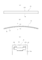
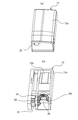
- 2A and 2B show a driving unit in the finger movement assisting device shown in FIG. 1, wherein FIG. 2A and 2B show a band member in the finger motion assisting device of FIG. 1, wherein FIG. 1A is a plan view, FIG. 2B is a side view, and FIG. 1C is a cross-sectional view taken along line AA in FIG. 7A and 7B show a driving unit in a finger motion assisting according to a modified example of the present invention, in which FIG. 7A is a perspective view showing its appearance, and FIG. 7B is a perspective view showing its internal structure.
- a finger movement assisting device 10 mainly includes a driving unit 12 arranged on the back side of a user's hand and a back of a finger of the hand from within the driving unit 12. It includes an extending strip 14, a fixing member 16, a support member 18, and a mounting portion 20.
- FIG. 1 shows, by way of example, a usage mode in which a finger motion assisting device 10 is used to assist the user in bending and expanding two fingers, the index finger and the middle finger, of the left hand.
- “front” means a direction from the base of the finger toward the fingertip
- “rear” means the opposite.
- the driving unit 12 includes a housing 12 a having a substantially rectangular parallelepiped shape, a motor 12 b having an output shaft fixed in the housing 12 a in the front-rear direction, and a motor 12 b.
- On the front surface of the housing 12a two T-shaped through holes 22, 22 through which the band plate members 14 are respectively inserted are formed.
- a flange 24 fixed to the mounting portion 20 is preferably formed at the lower end of the housing 12a over the entire circumference.
- the flange 24 be embedded in the resin.
- the motor 12b is driven by a current from a battery (not shown) provided inside or outside the housing 12a, and controls the forward / reverse rotation of the motor 12b via a control unit (not shown).
- the control unit has, for example, a sensor that detects a biological signal, and a calculation unit that outputs a control signal to the motor 12b based on the biological signal detected by the sensor. Based on a myoelectric potential signal generated in a muscle, it can be configured to assist a bending / extending operation of a finger corresponding to the muscle. Alternatively, the rotation direction and speed of the motor 12b may be directly operated using a controller (not shown).
- the transmission mechanism 12c includes a pair of bevel gears 28, 28, one of which is fixed to the output shaft of the motor 12b, the other being fixed to the drive shaft 26, and a spur gear fixed to both ends of the drive shaft 26. And two drive gears 30.
- the transmission mechanism 12c is not limited to the illustrated one as long as the power of the motor 12b can be transmitted to the band member 14 to move the band member 14 back and forth.
- a reduction gear may be incorporated in the transmission mechanism 12c.
- the band plate material 14 is a long body narrower than a finger, and preferably has a center in the longitudinal direction slightly curved in an upwardly convex shape in advance.
- the band plate material 14 has flexibility but has a certain degree of rigidity, and is resistant to tension and compression, that is, does not buckle when pulled out forward by the drive unit 12 as described later, and is drawn rearward. What has the strength which does not break is used.
- the band plate member 14 is made of synthetic resin or metal, and is preferably made of synthetic resin from the viewpoint of weight reduction. Further, a fiber reinforced plastic in which a reinforcing fiber such as a glass fiber or a carbon fiber is impregnated with a synthetic resin may be used. Alternatively, a composite material in which a metal band or a wire is covered with a synthetic resin may be used. Examples of the synthetic resin include, but are not limited to, polyethylene, polypropylene, polystyrene, and epoxy resin.
- a number of teeth 14a meshing with the drive gear 30 of the drive unit 12 are formed along the width direction orthogonal to the longitudinal direction.
- an engaging portion 14b that engages with the support member 18 (indicated by an imaginary line in the drawing) in the width direction is formed on the upper surface of the band plate member 14.
- two convex ridges 14b, 14b are formed along the left and right side edges of the band plate member 14, and the support member 18 has a convex portion 32 that enters the concave ridge between the engaging portions 14b.
- the arrangement may be reversed.
- the fixing member 16 fixes the distal end of the band plate member 14 and the finger on the distal end side of the second joint of the finger, and includes a contact portion 16a that contacts the back of the finger, and a contact portion 16a. And a fixing portion 16b extending upward from the fixing portion 16a.
- the lower surface of the contact portion 16a is formed of a curved surface that is curved in the width direction, whereby good contact with the back of the finger is obtained. Further, a hole 34 penetrating in the width direction is formed in the contact portion 16a.
- a fixing band (not shown) for fixing the fixing member 16 and the finger can be inserted through the hole 34.
- the strip 14 is inserted and fixed to the upper end of the fixing portion 16b.
- the fixing portion 16b also has a function as a spacer for maintaining a predetermined gap between the band plate member 14 and the finger.
- the support member 18 is fixed to the finger at the second joint of the finger or at a position closer to the first joint than the finger, and slidably supports the strip 14.
- the support member 18 has a contact portion 18a that contacts the back of the finger, and a guide portion 18b that extends upward from the contact portion 18a.
- the lower surface of the contact portion 18a is formed of a curved surface that is curved in the width direction, whereby good contact with the back of the finger is obtained.
- a hole 36 penetrating in the width direction is formed in the contact portion 18a.
- a fixing band (not shown) for fixing the support member 18 and the finger can be inserted through the hole 36.
- the band plate 14 is slidably inserted into the upper end of the guide portion 18b.
- the guide portion 18b also has a function as a spacer for maintaining a predetermined gap between the band plate member 14 and the finger.
- the mounting section 20 is for mounting and fixing the driving section 12 to the back of the hand.
- the mounting section 20 covers the upper half of the palm, preferably in the form of a hand of the user. It has a molded synthetic resin main body 20a and a connecting band (not shown) made of a surface fastener which is fixed to both sides of the main body 20a and is detachable from each other on the inner surface side of the hand.
- a hook may be used instead of the hook-and-loop fastener.
- a cushion layer such as urethane foam may be provided on the inner surface side of the main body 20a in order to enhance the contact with the hand.
- the operation of the finger motion assisting device 10 having the above configuration will be described.
- the motor 12 b of the driving unit 12 rotates in the first direction, and the band plate 14 is partially drawn into the driving unit 12 through the engagement between the driving gear 30 and the teeth 14 a of the band plate 14. .
- the fixing member 16 pulls up the tip of the finger, and the finger is deployed.
- the motor 12b of the drive section 12 rotates in the second direction, the strip 14 is fed out of the drive section 12 under the guide of the support member 18 through the engagement between the drive gear 30 and the teeth 14a of the strip 14.
- the band plate member 14 presses the fixing member 16 forward and bends itself, the fixing member 16 pushes down the tip of the finger, and the finger bends.
- the finger movement assisting device 10 of the present embodiment it is possible to assist the bending and the unfolding operation of the finger by the band plate material 14 having no joint, so that the structure is simple and small. , And the weight is light and easy to use. Also, there is no intimidation in appearance.
- the support member 18 is fixed to the finger at the second joint of the finger or at a position closer to the first joint than the finger and slidably supports the band plate 14, the front and rear of the band plate 14 are provided.
- the strip 14 does not buckle, giving a greater gripping assisting force to the user. can do.
- the band plate member 14 can be guided better.
- a lighter finger motion assisting device 10 can be provided.
- FIG. 1 shows an example in which the two band members 14 assist the bending and unfolding of two fingers
- the finger movement assisting device 10 may have only one band member 14.
- FIG. 4 shows the driving unit 12 in that case. The difference from the drive unit 12 shown in FIG. 3 is that only one drive gear 30 is provided on the drive shaft 26.
- the finger movement assisting device 10 may include three to five band plate members 14 and drive gears 30 corresponding to the band plate members 14. Further, in the above description, a case has been described in which the plurality of band members 14 are simultaneously operated by the power from one motor 12b, but each band member 14 may be driven by a separate motor 12b.
- a finger motion assisting device which is simple in structure, small in size, light in weight and easy to use.
Landscapes
- Health & Medical Sciences (AREA)
- Engineering & Computer Science (AREA)
- Life Sciences & Earth Sciences (AREA)
- Animal Behavior & Ethology (AREA)
- Epidemiology (AREA)
- Pain & Pain Management (AREA)
- Physical Education & Sports Medicine (AREA)
- Rehabilitation Therapy (AREA)
- Robotics (AREA)
- Mechanical Engineering (AREA)
- General Health & Medical Sciences (AREA)
- Public Health (AREA)
- Veterinary Medicine (AREA)
- Rehabilitation Tools (AREA)
- Manipulator (AREA)
- Prostheses (AREA)
Abstract
構造が簡単でかつ小型であり、重量も軽く使い勝手のよい指動作補助装置であって、指動作補助装置10は、正逆回転するモータ12bおよびモータ12bの作動によって回転する駆動歯車30を内蔵し、使用者の手の甲側に配置される駆動部12と、駆動部12内から手の指の背に沿って延出するとともに、駆動歯車30と噛み合う歯14aを有する屈曲性の帯板材14と、帯板材14と指とを該指の第2関節よりも先端側で固定する固定部材16とを備える。
Description
本発明は、人の手の指の屈曲、展開動作を補助する指動作補助装置に関する。
この種の指動作補助装置として、下記特許文献1では、手の甲に装着される基部と、その基部の端部から各指に向けて突出するようにその基部上に一体的に固着された第4節部と、その第4節部の先端部に第3関節部を介して揺動可能に後端部を連結された、手の指の第3節の背に装着される第3節部と、その第3節部の先端部に第2関節部を介して揺動可能に後端部を連結された、手の指の第2節の背に装着される第2節部と、その第2節部の先端部に第1関節部を介して揺動可能に後端部を連結された、手の指の第1節の背に装着される第1節部とを備えるものが提案されている。
このように、人の手の指の関節に対応した複数の関節部を有する従来の指動作補助装置は、構造が非常に複雑で部品点数が多く、重量も重いため使い勝手の点でも改良が望まれていた。
それ故本発明の目的は、構造が簡単でかつ小型であり、重量も軽く使い勝手のよい指動作補助装置を提供することにある。
本発明の指動作補助装置は、正逆回転するモータおよび前記モータの作動によって回転する駆動歯車を内蔵し、使用者の手の甲側に配置される駆動部と、前記駆動部内から前記手の指の背に沿って延出するとともに、前記駆動歯車と噛み合う歯を有する屈曲性の帯板材と、前記帯板材と前記指とを該指の第2関節よりも先端側で固定する固定部材とを備えている。
本発明の好適な態様では、前記指の前記第2関節上もしくはそれよりも第1関節側の位置で該指に固定され、前記帯板材を摺動可能に支持する支持部材を備える。
本発明の好適な態様では、前記帯板材は、前記指の背と対向する下面に前記歯を有し、その反対側の上面に前記支持部材と横方向で係合する係合部を有する。
本発明の好適な態様では、前記駆動部を前記手の甲に装着するための装着部を備える。
本発明の好適な態様では、前記帯板材は合成樹脂製である。
本発明の好適な態様では、前記帯板材を2以上備えるとともに、前記帯板材に対応する前記駆動歯車を2以上備え、該2以上の駆動歯車は同一の前記モータによって回転駆動される。
本発明の指動作補助装置によれば、関節部を持たない帯板材によって指の屈曲、展開動作を補助することが可能であるので、構造が簡単でかつ小型であり、重量も軽く使い勝手のよいものである。また、見た目にも威圧感がない。
以下、本発明の実施の形態を図面に基づき詳細に説明する。
本発明の一実施形態の指動作補助装置10は、図1に示すように、主として、使用者の手の甲側に配置される駆動部12と、駆動部12内から手の指の背に沿って延出する帯板材14と、固定部材16と、支持部材18と、装着部20とを備えている。図1は、一例として、指動作補助装置10を用いて使用者の左手の人差し指と中指の2本の指の屈曲、展開動作を補助する使用態様を示している。以下の説明において、前とは、指の付け根から指先に向かう方向であり、後とはその逆である。
図2に駆動部12の詳細を示すように、駆動部12は、略直方体をなすハウジング12aと、ハウジング12a内にその出力軸が前後方向に沿うように固定されたモータ12bと、モータ12bの回転を帯板材14の前後方向の直線移動に変換して伝達する伝達機構12cとを有する。ハウジング12aの前面には、帯板材14がそれぞれ挿通されるT字形の2つの貫通孔22,22が形成されている。また、ハウジング12aの下端部には、装着部20に固定されるフランジ24が好ましくは全周に亘って形成されている。装着部20の、少なくとも駆動部12が固定される部分(後述の本体20a)が樹脂から形成される場合には、フランジ24は当該樹脂内に埋め込むのが好ましい。
モータ12bは、ハウジング12a内または外に設けられた図示しないバッテリからの電流によって駆動し、図示しない制御部を介してその正逆回転を制御するのが好ましい。制御部は、例えば、生体信号を検出するセンサと、センサにより検出された生体信号に基づいてモータ12bへ制御信号を出力する演算部を有し、使用者が指を動作させようとした際に筋に生じる筋電位信号に基づき、該筋に対応する指の屈伸動作を補助するよう構成することができる。あるいは、図示しないコントローラを用いてモータ12bの回転方向や速度を直接操作してもよい。
伝達機構12cは、一方がモータ12bの出力軸に固定され、他方が駆動軸26に固定された一対のかさ歯車28,28と、駆動軸26の両端部に固定された、平歯車からなる2つの駆動歯車30とからなる。伝達機構12cは、モータ12bの動力を帯板材14に伝達して帯板材14を前後移動させることができれば図示のものに限定されない。伝達機構12cには減速機を組み込んでもよい。
帯板材14は、図3に示すように、指よりも狭幅な長尺体であり、予め長手方向中央を上方凸に僅かに湾曲させたものが好ましい。帯板材14は、屈曲性を有するがある程度の剛性を持ち、しかも引張、圧縮に強いもの、すなわち後述のように駆動部12によって前方に繰り出された際に座屈せず、後方に引き込まれた際に破断しない強度を有するものが使用される。帯板材14は合成樹脂製または金属製であり、軽量化の観点では合成樹脂製が好ましい。また、ガラス繊維や炭素繊維等の補強繊維に合成樹脂を含浸した繊維強化プラスチックを用いてもよい。あるいは、金属帯もしくは針金を合成樹脂で被覆した複合材を用いてもよい。合成樹脂には、例えば、ポリエチレンやポリプロピレン、ポリスチレン、エポキシ樹脂を用いることができるが、これらに限定されない。
帯板材14の下面には、駆動部12の駆動歯車30と噛み合う多数の歯14aが長手方向に直交する幅方向に沿って形成されている。また、帯板材14の上面には、図3(c)に示すように、支持部材18(図中、仮想線で示す。)と幅方向で係合する係合部14bが形成されている。図示例では、帯板材14の左右側縁に沿って2つの凸条の係合部14b,14bが形成され、支持部材18には、係合部14b間の凹条に入り込む凸部32が形成されているが、その配置関係は逆でもよい。
図1に戻り、固定部材16は、帯板材14の先端と指とを指の第2関節よりも先端側で固定するものであり、指の背に当接する当接部16aと、当接部16aから上方に延出した固定部16bとを有している。当接部16aの下面は、幅方向に湾曲した湾曲面で構成され、これにより指の背との良好な接触が得られる。また、当接部16aには幅方向に貫通した孔34が形成されている。この孔34には固定部材16と指とを固定する図示しない固定バンドを挿通させることができる。固定部16bの上端部には帯板材14が挿入され、固定されている。固定部16bは、帯板材14と指との間に所定の隙間を維持するスペーサとしての機能も有する。
図1に示すように、支持部材18は、指の第2関節上もしくはそれよりも第1関節側の位置で指に固定され、帯板材14を摺動可能に支持するものである。支持部材18は、指の背に当接する当接部18aと、当接部18aから上方に延在したガイド部18bとを有している。当接部18aの下面は、幅方向に湾曲した湾曲面で構成され、これにより指の背との良好な接触が得られる。また、当接部18aには幅方向に貫通した孔36が形成されている。この孔36には支持部材18と指とを固定する図示しない固定バンドを挿通させることができる。ガイド部18bの上端には、帯板材14が摺動可能に挿通されている。ガイド部18bは、帯板材14と指との間に所定の隙間を維持するスペーサとしての機能も有する。
装着部20は、図1に示すように、駆動部12を手の甲に装着、固定するためのものであり、図示例では、手のひらの上半部を覆う、好ましくは使用者の手を型にして成形された合成樹脂製の本体20aと、本体20aの両側部にそれぞれ固定され、手の内面側で互いに着脱自在な、面ファスナーからなる連結バンド(図示せず)とを有する。面ファスナーに代えてフックを用いてもよい。本体20aの内面側には、手との接触性を高めるためウレタンフォーム等のクッション層(図示せず)を設けてもよい。
次いで、上記構成を備える指動作補助装置10の動作を説明する。
まず、図1では、駆動部12のモータ12bが第1方向に回転し、駆動歯車30と帯板材14の歯14aとの噛み合いを介して帯板材14が駆動部12内に部分的に引き込まれる。これにより、帯板材14が固定部材16を引っ張るのに伴い、固定部材16が指の先端部を引き上げ、指が展開する。反対に、駆動部12のモータ12bが第2方向に回転すると、駆動歯車30と帯板材14の歯14aとの噛み合いを介して帯板材14が支持部材18のガイド下で駆動部12から繰り出される。これにより、帯板材14が固定部材16を前方に押圧すると共に自ら屈曲するのに伴い、固定部材16が指の先端部を押し下げ、指が屈曲する。
まず、図1では、駆動部12のモータ12bが第1方向に回転し、駆動歯車30と帯板材14の歯14aとの噛み合いを介して帯板材14が駆動部12内に部分的に引き込まれる。これにより、帯板材14が固定部材16を引っ張るのに伴い、固定部材16が指の先端部を引き上げ、指が展開する。反対に、駆動部12のモータ12bが第2方向に回転すると、駆動歯車30と帯板材14の歯14aとの噛み合いを介して帯板材14が支持部材18のガイド下で駆動部12から繰り出される。これにより、帯板材14が固定部材16を前方に押圧すると共に自ら屈曲するのに伴い、固定部材16が指の先端部を押し下げ、指が屈曲する。
このように、本実施形態の指動作補助装置10によれば、関節部を持たない帯板材14によって指の屈曲、展開動作を補助することが可能であるので、構造が簡単でかつ小型であり、重量も軽く使い勝手のよいものとなる。また、見た目にも威圧感がない。
特に、指の第2関節上もしくはそれよりも第1関節側の位置で指に固定され、帯板材14を摺動可能に支持する支持部材18を設けた好適な例では、帯板材14の前後移動をよりスムーズに行うことができるのに加えて、駆動部12によって帯板材14に大きな圧縮力を負荷した場合でも帯板材14が座屈せず、使用者に対してより大きな把持補助力を付与することができる。
また、帯板材14の上面に支持部材18と幅方向で係合する係合部14bを設けた好適な例では、帯板材14のガイドをより良好に行うことができる。
さらに、帯板材14を合成樹脂製とした好適な例では、より軽量な指動作補助装置10を提供することができる。
以上、図示例に基づき本発明を説明したが、本発明は上述の実施形態で示したものに限定されず、特許請求の範囲の開示内で適宜に変更することができる。図1では、2本の帯板材14で2本の指の屈曲、展開動作を補助する例を示したが、指動作補助装置10は、唯一の帯板材14を有するものでもよい。その場合の駆動部12を図4に示す。図3に示した駆動部12との違いは、駆動軸26に唯一の駆動歯車30が設けられている点である。図示しない他の変形例では、指動作補助装置10が3本以上5本以下の帯板材14と、各帯板材14に対応した駆動歯車30を備えたものでもよい。また、上記説明では、1つのモータ12bからの動力で複数の帯板材14を同時に作動させる場合について説明したが、各帯板材14を別々のモータ12bで駆動することもできる。
本発明によれば、構造が簡単でかつ小型であり、重量も軽く使い勝手のよい指動作補助装置を提供する。
10 指動作補助装置
12 駆動部
12b モータ
14 帯板材
14a 歯
14b 係合部
16 固定部材
18 支持部材
20 装着部
30 駆動歯車
12 駆動部
12b モータ
14 帯板材
14a 歯
14b 係合部
16 固定部材
18 支持部材
20 装着部
30 駆動歯車
Claims (6)
- 正逆回転するモータおよび前記モータの作動によって回転する駆動歯車を内蔵し、使用者の手の甲側に配置される駆動部と、
前記駆動部内から前記手の指の背に沿って延出するとともに、前記駆動歯車と噛み合う歯を有する屈曲性の帯板材と、
前記帯板材と前記指とを該指の第2関節よりも先端側で固定する固定部材とを備えることを特徴とする指動作補助装置。 - 前記指の前記第2関節上もしくはそれよりも第1関節側の位置で該指に固定され、前記帯板材を摺動可能に支持する支持部材を備える、請求項1に記載の指動作補助装置。
- 前記帯板材は、前記指の背と対向する下面に前記歯を有し、その反対側の上面に前記支持部材と横方向で係合する係合部を有する、請求項2に記載の指動作補助装置。
- 前記駆動部を前記手の甲に装着するための装着部を備える、請求項1から3までのいずれか一項に記載の指動作補助装置。
- 前記帯板材は合成樹脂製である、請求項1から4までのいずれか一項に記載の指動作補助装置。
- 前記帯板材を2以上備えるとともに、前記帯板材に対応する前記駆動歯車を2以上備え、該2以上の駆動歯車は同一の前記モータによって回転駆動される、請求項1から5までのいずれか一項に記載の指動作補助装置。
Applications Claiming Priority (2)
| Application Number | Priority Date | Filing Date | Title |
|---|---|---|---|
| JP2018127113A JP2021176342A (ja) | 2018-07-03 | 2018-07-03 | 指動作補助装置 |
| JP2018-127113 | 2018-07-03 |
Publications (1)
| Publication Number | Publication Date |
|---|---|
| WO2020009149A1 true WO2020009149A1 (ja) | 2020-01-09 |
Family
ID=69059181
Family Applications (1)
| Application Number | Title | Priority Date | Filing Date |
|---|---|---|---|
| PCT/JP2019/026462 Ceased WO2020009149A1 (ja) | 2018-07-03 | 2019-07-03 | 指動作補助装置 |
Country Status (2)
| Country | Link |
|---|---|
| JP (1) | JP2021176342A (ja) |
| WO (1) | WO2020009149A1 (ja) |
Cited By (2)
| Publication number | Priority date | Publication date | Assignee | Title |
|---|---|---|---|---|
| CN111544164A (zh) * | 2020-05-13 | 2020-08-18 | 西安交通大学 | 一种单向拉线式柔性假肢手指 |
| WO2021215513A1 (ja) * | 2020-04-23 | 2021-10-28 | 学校法人慶應義塾 | 指動作補助装置 |
Citations (4)
| Publication number | Priority date | Publication date | Assignee | Title |
|---|---|---|---|---|
| JP2013529937A (ja) * | 2010-03-23 | 2013-07-25 | イドロジェネット エスアールエル | 手リハビリ装置 |
| JP2015123563A (ja) * | 2013-12-27 | 2015-07-06 | 本田技研工業株式会社 | 関節機構 |
| JP2016068192A (ja) * | 2014-09-30 | 2016-05-09 | セイコーエプソン株式会社 | ロボットハンド及びロボット |
| JP2017023448A (ja) * | 2015-07-23 | 2017-02-02 | 原田電子工業株式会社 | 指動作補助装置 |
-
2018
- 2018-07-03 JP JP2018127113A patent/JP2021176342A/ja active Pending
-
2019
- 2019-07-03 WO PCT/JP2019/026462 patent/WO2020009149A1/ja not_active Ceased
Patent Citations (4)
| Publication number | Priority date | Publication date | Assignee | Title |
|---|---|---|---|---|
| JP2013529937A (ja) * | 2010-03-23 | 2013-07-25 | イドロジェネット エスアールエル | 手リハビリ装置 |
| JP2015123563A (ja) * | 2013-12-27 | 2015-07-06 | 本田技研工業株式会社 | 関節機構 |
| JP2016068192A (ja) * | 2014-09-30 | 2016-05-09 | セイコーエプソン株式会社 | ロボットハンド及びロボット |
| JP2017023448A (ja) * | 2015-07-23 | 2017-02-02 | 原田電子工業株式会社 | 指動作補助装置 |
Cited By (4)
| Publication number | Priority date | Publication date | Assignee | Title |
|---|---|---|---|---|
| WO2021215513A1 (ja) * | 2020-04-23 | 2021-10-28 | 学校法人慶應義塾 | 指動作補助装置 |
| JPWO2021215513A1 (ja) * | 2020-04-23 | 2021-10-28 | ||
| JP7709171B2 (ja) | 2020-04-23 | 2025-07-16 | 慶應義塾 | 指動作補助装置 |
| CN111544164A (zh) * | 2020-05-13 | 2020-08-18 | 西安交通大学 | 一种单向拉线式柔性假肢手指 |
Also Published As
| Publication number | Publication date |
|---|---|
| JP2021176342A (ja) | 2021-11-11 |
Similar Documents
| Publication | Publication Date | Title |
|---|---|---|
| JP5826862B2 (ja) | 挿入装置 | |
| KR102679703B1 (ko) | 보행 보조 장치 | |
| JP5927173B2 (ja) | 関節機構 | |
| JP5244029B2 (ja) | 歩行補助装置 | |
| US6158757A (en) | Motion conversion assembly and vehicle | |
| JP4102320B2 (ja) | 内視鏡 | |
| CN106853842B (zh) | 电动助力转向装置 | |
| JP2021176342A (ja) | 指動作補助装置 | |
| CN112077828B (zh) | 助力外骨骼 | |
| JP2017013157A (ja) | 脚部又は腕部動作支援式ウエアラブルロボット | |
| KR20130065032A (ko) | 스티어링 휠 내장형 스위치 모듈 | |
| JP2014180298A (ja) | 指アシスト装置 | |
| CN204246321U (zh) | 头带结构以及焊接面罩 | |
| JP2012176083A (ja) | リハビリ用手袋 | |
| JP6501358B2 (ja) | 指動作補助装置 | |
| JP4718581B2 (ja) | 身障者用車椅子 | |
| JP7709171B2 (ja) | 指動作補助装置 | |
| JP6550298B2 (ja) | 力伝達フレーム及びこれを含む運動補助装置 | |
| JP4529550B2 (ja) | 携帯式動力工具 | |
| WO2007136853A3 (en) | Medical device using beam construction and methods | |
| JP4299221B2 (ja) | 作業機の舵取り装置 | |
| JP2018199037A (ja) | 指動作補助装置 | |
| KR20090089602A (ko) | 효자손 장치 | |
| CN215080520U (zh) | 调节装置和矫姿带 | |
| JP2020196090A (ja) | アシスト装置 |
Legal Events
| Date | Code | Title | Description |
|---|---|---|---|
| 121 | Ep: the epo has been informed by wipo that ep was designated in this application |
Ref document number: 19830649 Country of ref document: EP Kind code of ref document: A1 |
|
| NENP | Non-entry into the national phase |
Ref country code: DE |
|
| 122 | Ep: pct application non-entry in european phase |
Ref document number: 19830649 Country of ref document: EP Kind code of ref document: A1 |
|
| NENP | Non-entry into the national phase |
Ref country code: JP |