WO2020008929A1 - 送信装置、受信装置、および伝送システム - Google Patents
送信装置、受信装置、および伝送システム Download PDFInfo
- Publication number
- WO2020008929A1 WO2020008929A1 PCT/JP2019/024887 JP2019024887W WO2020008929A1 WO 2020008929 A1 WO2020008929 A1 WO 2020008929A1 JP 2019024887 W JP2019024887 W JP 2019024887W WO 2020008929 A1 WO2020008929 A1 WO 2020008929A1
- Authority
- WO
- WIPO (PCT)
- Prior art keywords
- frame
- redundant
- transmission
- divided
- channel
- Prior art date
- Legal status (The legal status is an assumption and is not a legal conclusion. Google has not performed a legal analysis and makes no representation as to the accuracy of the status listed.)
- Ceased
Links
Images


Classifications
-
- H—ELECTRICITY
- H04—ELECTRIC COMMUNICATION TECHNIQUE
- H04L—TRANSMISSION OF DIGITAL INFORMATION, e.g. TELEGRAPHIC COMMUNICATION
- H04L1/00—Arrangements for detecting or preventing errors in the information received
- H04L1/08—Arrangements for detecting or preventing errors in the information received by repeating transmission, e.g. Verdan system
-
- H—ELECTRICITY
- H04—ELECTRIC COMMUNICATION TECHNIQUE
- H04L—TRANSMISSION OF DIGITAL INFORMATION, e.g. TELEGRAPHIC COMMUNICATION
- H04L1/00—Arrangements for detecting or preventing errors in the information received
- H04L1/0001—Systems modifying transmission characteristics according to link quality, e.g. power backoff
- H04L1/0006—Systems modifying transmission characteristics according to link quality, e.g. power backoff by adapting the transmission format
- H04L1/0007—Systems modifying transmission characteristics according to link quality, e.g. power backoff by adapting the transmission format by modifying the frame length
-
- H—ELECTRICITY
- H04—ELECTRIC COMMUNICATION TECHNIQUE
- H04L—TRANSMISSION OF DIGITAL INFORMATION, e.g. TELEGRAPHIC COMMUNICATION
- H04L1/00—Arrangements for detecting or preventing errors in the information received
- H04L1/12—Arrangements for detecting or preventing errors in the information received by using return channel
- H04L1/16—Arrangements for detecting or preventing errors in the information received by using return channel in which the return channel carries supervisory signals, e.g. repetition request signals
- H04L1/18—Automatic repetition systems, e.g. Van Duuren systems
- H04L1/1809—Selective-repeat protocols
-
- H—ELECTRICITY
- H04—ELECTRIC COMMUNICATION TECHNIQUE
- H04L—TRANSMISSION OF DIGITAL INFORMATION, e.g. TELEGRAPHIC COMMUNICATION
- H04L1/00—Arrangements for detecting or preventing errors in the information received
- H04L1/22—Arrangements for detecting or preventing errors in the information received using redundant apparatus to increase reliability
Definitions
- the present invention relates to a transmitting device, a receiving device, and a transmission system.
- the transmission method according to the above-described conventional technique has a problem that the use efficiency of the transmission / reception unit may be low because the fixed transmission / reception unit is allocated to the generated divided frames.
- FIG. 6 is a schematic diagram showing an example for explaining a problem in the related art.
- the client 1 has two data channels for transmitting data and one redundant channel that switches if any of them fails.
- the client 2 has two data channels and two redundant channels.
- the redundancy of the client 1 becomes 0 due to the use of the redundant channel.
- a redundant channel generated due to a failure of the transmitting / receiving unit is replaced with a redundant channel. May not be able to assign the transmission / reception unit assigned to.
- the present invention has been made in view of the above problem recognition, and provides a transmission device, a reception device, and a transmission system that can flexibly set a data channel and a redundant channel and increase the use efficiency of a transmission / reception unit.
- a transmission device generates a divided frame by dividing a frame into one or more, adds an error detection signal to each of the generated divided frames, A frame processing unit for outputting the divided frame to which the error detection signal is added to a plurality of data channels, and at least one redundancy including restoration information enabling restoration of the divided frame when an error of the divided frame is detected
- a redundant channel processing unit that generates a frame from the divided frame and outputs the data to a data channel, the divided frame output from the frame processing unit, and the redundant frame output from the redundant channel processing unit,
- a transmitting / receiving unit to be output, and assigning the divided frame and the redundant frame to the assignable transmitting / receiving unit.
- One aspect of the present invention is the transmission apparatus described above, further comprising: a redundant channel processing group having one or more redundant channel processing units; and two or more frame processing units being the redundant channel processing group. And the redundant channel processing group generates a number of redundant frames up to the number of redundant frames that can be generated by the redundant channel processing group based on the divided frames output by any of the frame processing units. Is the thing.
- the receiving device includes a divided frame generated by dividing a frame into one or more and adding an error detection code, or the divided frame generated when a transmission error of the divided frame occurs.
- An error detection process is performed by a transmission / reception unit that inputs a redundant frame generated so as to include restoration information enabling restoration from a transmission path, and the error detection code added to the divided frame passed from the transmission / reception unit.
- a frame processing unit that outputs the frame based on the divided frame when no error is detected, and based on the divided frame restored using the redundant frame when an error is detected.
- the frame processing unit detects an error based on the error detection code, Comprising a distribution, abnormal based on said divided frame of the data channel that has not been detected, and a redundant channel processing unit abnormalities restore the divided frames of the detected data channel.
- a transmission system includes the transmission device according to [1] or [2], the reception device according to [3], and the frame processing in the transmission device. Setting the number of redundant channels transmitted from the data channel processing unit in the transmission device and the transmission / reception unit selected by the channel selection unit in the transmission device for the divided frame transmitted from the transmission unit And a system.
- a plurality of divided frames generated from the main signal and a frame included in the redundant channel share a plurality of transmission / reception units.
- each of the divided frames is assigned to an arbitrary data channel generated by the transmission / reception unit, and an arbitrary number of redundant channels is assigned to these.
- the setting of the data channel and the redundant channel can be flexibly and efficiently realized without causing an instantaneous interruption.
- FIG. 1 is a block diagram illustrating a schematic functional configuration of a transmission system according to a first embodiment of the present invention. It is a schematic diagram showing a first application example of the same embodiment. It is a schematic diagram showing a second application example of the embodiment.
- FIG. 7 is a block diagram illustrating a schematic functional configuration of a transmission system according to a second embodiment of the present invention.
- FIG. 13 is a block diagram illustrating a schematic functional configuration of a transmission system according to a third embodiment of the present invention.
- FIG. 9 is a schematic diagram showing an example for explaining a problem in the conventional technology.
- FIG. 1 is a block diagram illustrating a schematic functional configuration of the transmission system according to the first embodiment.
- the transmission system includes a transmission line 101 and communication node devices 1 and 2 at the end points.
- the communication node device 1 is a communication node device (transmitting device) on the transmitting side
- the communication node device 2 is a communication node device (receiving device) on the receiving side.
- the signal flow is shown in only one direction (the direction from the communication node device 1 to the communication node device 2) in the same drawing, since the communication node device has both functions of the transmission side and the reception side, the flow of the signal is bidirectional. Communication can be easily realized.
- the communication node device 1 on the transmission side includes a plurality of frame processing units 21, a plurality of redundant channel processing units 22, a channel selection unit 23, and a plurality of transmission / reception units 24.
- the communication node device 2 on the receiving side includes a plurality of frame processing units 61, a plurality of redundant channel processing units 62, a channel selection unit 63, and a plurality of transmission / reception units 64.
- one redundant channel processing unit 22 is provided for each frame processing unit 21 in the communication node device 1.
- one redundant channel processing unit 62 is provided for each frame processing unit 61.
- each unit constituting the communication node device 1 transmits to transmission side.
- the frame processing unit 21 generates one or more divided frames based on a client signal (frame before being divided) input to the transmission system.
- the frame processing unit 21 adds an error detection signal to the generated divided frame.
- the communication node device 2 on the receiving side can detect which channel has a failure.
- the frame processing unit 21 outputs the divided frame to which the error detection signal has been added to a plurality of data channels.
- the redundant channel processing unit 22 generates one or more redundant frames based on the divided frames generated by the frame processing unit 21.
- the redundant frame includes restoration information that can be used by the communication node device 2 on the receiving side.
- the communication node device 2 on the receiving side uses the normal data channel in which the failure is not detected and the restoration information included in the redundant frame to perform the failure.
- the transmission frame contained in the detected channel is restored.
- an error detection code may be added to the redundant frame.
- the number of redundant channels that can be generated by the redundant channel processing unit 22 is one or more.
- a plurality of redundant channels may be configured by duplicating one redundant frame, or M-out-of-N coding may be used. That is, the redundant channel processing unit 22 generates one or more redundant frames including restoration information that enables restoration of the divided frame when an error in the divided frame is detected, and outputs the redundant frame to the data channel.
- the channel selection unit 23 accommodates a plurality of divided frames generated by the frame processing unit 21 based on the client signal and a plurality of redundant frames generated by the redundant channel processing unit 22, and allocates these frames to the transmission / reception unit 24, respectively.
- the transmission / reception unit that the channel selection unit 23 selects as a frame allocation destination is arbitrary. For example, a frame generated by a certain frame processing unit 21 is allocated to two transmission / reception units 24, and a frame generated by another frame processing unit 21 is transmitted to another transmission / reception unit 24 between the two transmission / reception units 24. May be assigned. That is, the channel selection unit 23 allocates the divided frame and the redundant frame to the assignable transmission / reception unit 24.
- the transmitting / receiving unit 24 sends out the allocated frame to the transmission path.
- the transmission / reception unit 24 may have a function of adding an error correction code based on FEC (Forward Error Correction) when transmitting a frame. That is, the transmission / reception unit 24 outputs the divided frame output from the frame processing unit 21 and the redundant frame output from the redundant channel processing unit 22 to the transmission path.
- FEC Forward Error Correction
- the transmission signal transmitted from the transmission / reception unit 24 reaches the transmission / reception unit 64 of the communication node device 2 on the reception side via the transmission path.
- a cross-connect unit selects a route for each transmission / reception unit in a transmission path section.
- the receiving-side communication node device 2 performs a receiving process that is the reverse of the process in the transmitting-side communication node device 1. That is, it is as follows.
- the transmission / reception unit 64 receives a transmission signal.
- the transmission / reception unit 64 performs an error correction process as needed.
- the transmission / reception unit 64 passes the received transmission frame and redundant frame to the channel selection unit 63. That is, the transmission / reception unit 64 may include the divided frame generated by dividing the frame into one or more and adding the error detection code, or the restoration information that enables the restoration of the divided frame when the transmission error of the divided frame occurs.
- the generated redundant frame is input from a transmission path.
- the channel selection unit 63 distributes each transmission frame and redundant frame passed from the transmission / reception unit 64 to an appropriate frame processing unit 61 or redundant channel processing unit 62.
- the redundant channel processing unit 62 restores the transmission frame based on the restoration information included in the redundant frame and the transmission frame in which no error is detected. Only when the following frame processing unit 61 detects an error in the transmission frame, the redundant channel processing unit 62 may restore the transmission frame related to the error. That is, when the frame processing unit 61 detects an error based on the error detection code, the redundant channel processing unit 62 uses the restoration information included in the redundant frame and the divided frame of the data channel in which no abnormality is detected. Then, the divided frame of the data channel in which the abnormality is detected is restored.
- the frame processing unit 61 restores the client signal based on the transmission frame.
- the frame processing unit 61 performs an operation on the error detection code added to the transmission frame to determine whether there is an error.
- the frame processing unit 61 converts the transmission frame restored by the redundant channel processing unit 62 based on the restoration information included in the redundant frame and the transmission frame in which no error is detected.
- the client signal (the original frame before division) is restored and output. That is, the frame processing unit 61 performs an error detection process using the error detection code added to the divided frame passed from the transmission / reception unit 64.
- the original frame is reconstructed and output based on the divided frame, and when an error is detected, based on the divided frame restored using the redundant frame.
- FIG. 2 is a schematic diagram showing a first application example of the present embodiment.
- FIG. 3A shows an initial state
- FIG. 3B shows a failure state.
- the process starts from the initial state (a) and shifts to the fault state (b) when a fault occurs at a predetermined time in the middle.
- the cross-connect unit 106 in the transmission path section controls the connection relationship between the transmission / reception unit 24 and the output destination path.
- (A) Initial State As shown in the figure, a plurality of client signals including a data channel and a redundant channel are input to the channel selection unit 23, and further output to the transmission line 101 via the transmission / reception unit 24.
- the number of redundant channels for the data channel and the route in which client signals of those channels are transmitted may be different for each client signal.
- a client 1 and a client 2 exist. Regarding the client 1, signals of two data channels and one redundant channel are output to the route A in the initial state. Regarding the client 2, similarly, signals of one data channel and two redundant channels are output to the route B in the initial state.
- (B) Failure state Here, it is assumed that a failure occurs in the transmission / reception unit of one of the data channels or the redundant channels of the client 1 that has output to the route A.
- Client 1 has one redundant channel. Therefore, the occurrence of a failure is detected by the communication node device 2 on the receiving side, and if the failed channel is a data channel, the redundant signal processing unit 62 on the receiving side causes an instantaneous interruption of the failed signal. It can be restored normally without causing the error. At this point, the number of redundant channels of the client 1 becomes zero. However, the channel selection unit 23 reassigns the transmission / reception unit 24 assigned to the redundant channel on the client 2 side to the client 1. Further, the connection relationship of the cross connect unit 106 is changed accordingly.
- control is performed so that the assignment destination corresponding to the transmitting / receiving unit 24 reassigned from the client 2 to the client 1 is changed from the route B to the route A.
- it is possible to secure at least one redundant channel for each of the clients 1 and 2.
- FIG. 3 is a schematic diagram showing a second application example of the present embodiment.
- two clients having the same route are connected to the channel selection unit 23.
- FIG. 7A shows the initial state
- FIG. 7B shows the transition destination state.
- the process starts from the initial state (a) and shifts to the transition destination state (b) when a request to improve the reliability of the client 1 is generated at a predetermined time in the middle.
- the transmission / reception unit 24 that has been a free resource can be used to satisfy the request. That is, the channel selection unit 23 changes the transmission / reception unit 24, which has been a free resource, to be assigned to the client 1. As a result, the number of channels used by the client 1 increases, and the reliability of communication relating to the client 1 improves.
- the channel selection unit 23 switches between the data channel and the redundant channel, so that the unallocated transmission / reception unit can be applied to uses such as failure recovery and improvement of reliability for arbitrary clients having different routes. it can.
- one redundant channel processing unit 22 is provided for each frame processing unit 21 in the communication node device 1. Further, in the communication node apparatus 2, one redundant channel processing unit 62 is provided for each frame processing unit 61. In the first embodiment, the upper limit value of the number of redundant channels that can be set for the frame processing unit 21 accommodating each client signal is determined by the redundant channel processing unit 22.
- the redundant channel processing group 27G including the redundant channel processing units 27 is shared by the frame processing units 21. Further, in the present embodiment, in the communication node device 4 on the receiving side, a redundant channel processing group 67G including a plurality of redundant channel processing units 67 is shared by a plurality of frame processing units 61.
- FIG. 4 is a block diagram showing a schematic functional configuration of the transmission system according to the second embodiment.
- the transmission system includes a transmission line 101 and communication node devices 3 and 4 at the end points.
- the communication node device 3 is a communication node device (transmitting device) on the transmitting side
- the communication node device 4 is a communication node device (receiving device) on the receiving side.
- the signal flow is shown in only one direction (the direction from the communication node device 1 to the communication node device 2) in the same drawing, since the communication node device has both functions of the transmission side and the reception side, the flow of the signal is bidirectional. Communication can be easily realized.
- the communication node device 3 on the transmission side includes a plurality of frame processing units 21, a redundant channel processing group 27G including a plurality of redundant channel processing units 27, a channel selection unit 23, and a plurality of transmission / reception units 24. Is done.
- the communication node device 4 on the receiving side includes a plurality of frame processing units 61, a redundant channel processing group 67G including a plurality of redundant channel processing units 67, a channel selection unit 63, and a plurality of transmission / reception units 64. Is done.
- the redundant channel processing group 27G includes one or more redundant channel processing units 27.
- the redundant channel processing group 27G is shared by two or more frame processing units 21.
- the redundant channel processing group 27G generates the number of redundant frames up to the number of redundant frames that can be generated by the redundant channel processing group 27G, based on the divided frames output from the arbitrary frame processing unit 21.
- the redundant channel processing group 27G has a function of selecting which redundant channel processing unit 27 accommodates a frame copied from each frame processing unit 21. With this configuration, the maximum number of redundant channels that can be generated from a single frame processing unit 21 is (the number of redundant channels that can be generated by one redundant channel processing unit 27) ⁇ (the number of redundant channel processing units 27). Become.
- the redundant channel processing unit 27 can be used more efficiently than in the case of the first embodiment.
- the operation system arranged at a remote place is provided with a function of selecting the number of redundant channels transmitted from the data channel processing unit and the channel selection unit for the divided frame transmitted from the frame processing unit in the communication node device. This is the point of setting and controlling the transmission / reception unit selected by.
- FIG. 5 is a block diagram illustrating a schematic functional configuration of the transmission system according to the third embodiment.
- this transmission system is configured to include transmission lines 101, 102, and 103, communication node devices 5, 6, and 7 arranged at the end points of the transmission lines, and an operation system 121.
- the transmission path 101 is a transmission path that directly connects the communication node device 5 and the communication node device 6.
- the transmission path 102 is a transmission path that directly connects the communication node device 5 and the communication node device 7.
- the transmission path 103 is a transmission path that directly connects the communication node device 7 and the communication node device 6.
- the communication node device 5 is a communication node device (transmitting device) on the transmitting side
- the communication node device 6 is a communication node device (receiving device) on the receiving side.
- the communication node device 7 has a role of relaying data transmission from the communication node device 5 to the communication node device 6.
- a route from the communication node device 5 to the communication node device 6 there is a route via the transmission line 101 and a route via the transmission line 102, the communication node device 7, and the transmission line 103.
- the communication node device 5 on the transmission side includes a plurality of frame processing units 21, a plurality of redundant channel processing units 22, a channel selection unit 23, a plurality of transmission / reception units 24, a control unit 28, a cross-connect unit 107, It is comprised including.
- the communication node device 6 on the receiving side includes a plurality of frame processing units 61, a plurality of redundant channel processing units 62, a channel selection unit 63, a plurality of transmission / reception units 64, a control unit 68, a cross-connect unit 108, It is comprised including.
- the communication node device 7 has a function as a transmitting device of the communication node device 5 and a function as a receiving device of the communication node device 6. Further, the communication node device 7 is also configured to include the control unit 78.
- the cross-connect unit 107 in the communication node device 5 controls connection of each of the plurality of transmission / reception units 24 for each transmission path.
- the cross-connect unit 108 in the communication node device 6 controls connection of each of the plurality of transmission / reception units 64 for each route.
- the feature of this embodiment is that the communication node device 5 has the control unit 28, the communication node device 6 has the control unit 68, and the communication node device 7 has the control unit 78.
- the operation system 121 unique to the present embodiment performs bidirectional communication with each of the control units 28, 68, and 78.
- the operation system 121 may be installed at a location remote from each of the communication node devices 5, 6, and 7.
- the operation system 121 controls the communication node devices 5, 6, and 7 via the control units 28, 68, and 78, respectively.
- the specific contents of the control are as follows.
- the control units 28, 68, 78 of the communication node devices 5, 6, 7 respectively notify the operation system 121 of the abnormality when the abnormality of the data channel is detected.
- the operation system 121 receives the data channel abnormality information notified from the control unit 28.68.78.
- the operation system 121 acquires information about demand such as new setting of the frame processing unit, bandwidth increase or bandwidth decrease, and improvement of redundancy from outside (for example, via a user interface of the operation system 121). .
- the operation system 121 determines the allocation destination of the divided frame or the redundant frame on the basis of the above-described abnormality notification of the data channel, the new setting of the frame processing unit, the speed-up or the speed-down of the band, and the demand for the improvement of the redundancy.
- the transmission / reception unit is determined, and the distribution destination in the channel selection unit is set.
- This setting by the operation system 121 is transmitted to the control units 28, 68, and 78 of the communication node devices 5, 6, and 7, respectively, and the setting is performed on the communication node device side.
- the operation system 121 determines the number of redundant channels transmitted from the data channel processing unit in the transmission-side communication node device and the number of redundant channels transmitted from the frame processing unit in the transmission-side communication node device. It controls and sets the transmission / reception unit selected by the channel selection unit in the node device.
- the present embodiment and the second embodiment may be implemented in combination.
- the communication node device has a redundant channel processing group. That is, each communication node device includes a redundant channel processing group (27G, 67G), similarly to the communication node devices 3 and 4 shown in FIG.
- Each communication node device includes a control unit (28, 68, 78), similarly to the communication node device 5, the communication node device 6, and the communication node device 7 illustrated in FIG. Then, the operation system 121 controls, via the control unit of each communication node device, to which redundant channel processing unit the divided frame generated by each frame processing unit is assigned.
- the operation system 121 has a control function and performs various settings and controls for each communication node device.
- the operation system 121 may be provided in a place remote from the communication node device. This makes it possible to easily configure a redundant system including a plurality of channels.
- a program for realizing this function may be recorded on a computer-readable recording medium, and the program recorded on this recording medium may be read into a computer system and executed.
- the “computer system” includes an OS and hardware such as peripheral devices.
- the “computer-readable recording medium” is a portable medium such as a flexible disk, a magneto-optical disk, a ROM, a CD-ROM, a DVD-ROM, a USB memory, or a storage device such as a hard disk built in a computer system. That means.
- a "computer-readable recording medium” is a medium that temporarily and dynamically holds a program, such as a communication line for transmitting a program through a network such as the Internet or a communication line such as a telephone line.
- a program holding a program for a certain period of time such as a volatile memory in a computer system serving as a server or a client, may be included.
- the above-mentioned program may be for realizing a part of the above-mentioned functions, or may be for realizing the above-mentioned functions in combination with a program already recorded in a computer system.
- the present invention can be used, for example, for data communication.
- the scope of use of the present invention is not limited to those exemplified here.
Landscapes
- Engineering & Computer Science (AREA)
- Computer Networks & Wireless Communication (AREA)
- Signal Processing (AREA)
- Quality & Reliability (AREA)
- Detection And Prevention Of Errors In Transmission (AREA)
- Data Exchanges In Wide-Area Networks (AREA)
Abstract
送信装置は、フレーム処理部と、冗長チャネル処理部と、送受信部と、チャネル選択部とを備える。フレーム処理部は、分割フレームを生成し、分割フレームのそれぞれに誤り検出信号を付加し、誤り検出信号を付加した分割フレームを複数のデータチャネルに出力する。冗長チャネル処理部は、分割フレームの復元を可能とする復元情報を含む1以上の冗長フレームを前記分割フレームから生成してデータチャネルに出力する。送受信部は、分割フレームおよび冗長フレームを、伝送路に出力する。チャネル選択部は、前記分割フレームおよび前記冗長フレームを、それぞれ割り当て可能な前記送受信部に割り当てる。
Description
本発明は、送信装置、受信装置、および伝送システムに関する。
通信網におけるトラフィックの大容量化に対応するために、伝送システムにおいては、主信号から生成されたフレームを並列に分割し、複数のデータチャネルに割り当てて伝送を行う方法が一般的となりつつある。一方で、データチャネルを生成する送受信部の信頼性はトラフィック量によらず一定であるため、複数の送受信部のうちいずれかの故障が発生する確率は、トラフィック増加に伴うデータチャネルの並列数の増加に比例して高くなる。
上記の故障の発生に対処するため、クライアント信号から生成されるフレームに対して冗長処理を加え、主信号の含まれるデータチャネルに加えて冗長チャネルとして並列伝送する方法が考案されている(特許文献1)。この方法では、前記フレームを複数の送受信部で各々データチャネルに割り当てた構成において、任意の箇所のデータチャネルに障害が発生した際に、障害の発生したデータチャネルを検出する。そして、この方法では、障害の発生していないデータチャネルに含まれるフレームと、冗長チャネルに含まれる復元情報とから、障害の発生したデータチャネルに含まれるフレームを復元する。これにより、任意の送受信部あるいは伝送路に障害が発生しても、通信の瞬断が発生することなく通信を継続することができる。
しかしながら、上記の従来技術による伝送方法では、生成された分割フレームに対して固定的な送受信部が割り当てられることにより、送受信部の利用効率が低い場合があるという課題がある。
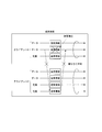
図6は、従来技術における課題を説明するための例を示す概略図である。図示する状況において、クライアント1は、データを伝送する2つのデータチャネルと、それらのいずれかが故障した際に切り替わる1つの冗長チャネルを有する。また、クライアント2は、2つのデータチャネルと2つの冗長チャネルを有する。ここで、クライアント1のデータチャネルのうち1つの送受信部に障害が発生した場合、クライアント1の冗長チャネルを用いることによって通信断を防ぐことができる。ここで、冗長チャネルを用いたことによって、クライアント1の冗長度は0になってしまう。クライアント1の冗長度が0になることを回避するためには、クライアント2が持つ2つの冗長チャネルのうち1つの送受信部をクライアント1と共有することができればよい(図6の破線で示す割り当て)。これができる場合には、クライアント1、2とも冗長チャネルを確保することができる。しかしながら、送受信部が個々のクライアントに対して固定的に設定されている場合や、各々のクライアントが異なる宛先に設定されている場合には、送受信部の障害によって発生した空きチャネルに対し、冗長チャネルに割り当てられていた送受信部を割り当てることができない場合が発生し得る。
本発明は、上記の課題認識に鑑み為されたもので、データチャネルおよび冗長チャネルの設定を柔軟にし、送受信部の利用効率を高めることのできる送信装置、受信装置、および伝送システムを提供する。
[1]上記の課題を解決するため、本発明の一態様による送信装置は、フレームを1以上に分割して分割フレームを生成し、生成した前記分割フレームのそれぞれに誤り検出信号を付加し、誤り検出信号を付加した前記分割フレームを複数のデータチャネルに出力するフレーム処理部と、前記分割フレームの誤りが検出された際に前記分割フレームの復元を可能とする復元情報を含む1以上の冗長フレームを前記分割フレームから生成してデータチャネルに出力する冗長チャネル処理部と、前記フレーム処理部から出力された前記分割フレーム、および前記冗長チャネル処理部から出力された前記冗長フレームを、伝送路に出力する送受信部と、前記分割フレームおよび前記冗長フレームを、それぞれ割り当て可能な前記送受信部に割り当てるチャネル選択部と、を備える。
[2]また、本発明の一態様は、上記の送信装置において、1以上の前記冗長チャネル処理部を有する冗長チャネル処理群、を備え、2以上の前記フレーム処理部が、前記冗長チャネル処理群を共有し、前記冗長チャネル処理群は、任意の前記フレーム処理部が出力した前記分割フレームを基に、前記冗長チャネル処理群が生成可能な冗長フレーム数を上限とした数の冗長フレームを生成する、ものである。
[3]また、本発明の一態様による受信装置は、フレームを1以上に分割し且つ誤り検出符号を付加することによって生成された分割フレームを、または前記分割フレームの伝送エラー時に前記分割フレームの復元を可能とする復元情報を含むよう生成された冗長フレームを、伝送路から入力する送受信部と、前記送受信部から渡される前記分割フレームに付加された前記誤り検出符号により誤り検出の処理を行うとともに、誤りが検出されなかった場合には当該分割フレームに基づき、また誤りが検出された場合には前記冗長フレームを用いて復元された前記分割フレームに基づき、前記フレームを出力するフレーム処理部と、前記フレーム処理部が前記誤り検出符号に基づいて誤りを検出した場合に、前記冗長フレームに含まれる復元情報と、異常が検出されなかったデータチャネルの前記分割フレームとに基づいて、異常が検出されたデータチャネルの分割フレームを復元する冗長チャネル処理部と、を備える。
[4]また、本発明の一態様による伝送システムは、上の[1]または[2]に記載の送信装置と、上の[3]に記載の受信装置と、前記送信装置における前記フレーム処理部から送出される分割フレームに対して、前記送信装置における前記データチャネル処理部から送出される冗長チャネル数と、前記送信装置における前記チャネル選択部にて選択される送受信部とを、設定するオペレーションシステムと、を有する。
本発明によれば、主信号から生成された複数の分割フレームと、冗長チャネルに含まれるフレームとが、複数の送受信部を共有する。これにより、分割フレームの各々を、送受信部で生成される任意のデータチャネルに割り当て、さらに、これらに対して任意数の冗長チャネル数を付与する。これにより、データチャネルおよび冗長チャネルの設定を、瞬断を発生させることなく柔軟かつ効率的に実現できる。
次に、本発明の実施形態について、図面を参照しながら説明する。
[第1実施形態]
図1は、第1実施形態による伝送システムの概略機能構成を示すブロック図である。図示するように、この伝送システムは、伝送路101と、その端点における通信ノード装置1および2とを含んで構成される。通信ノード装置1は送信側の通信ノード装置(送信装置)であり、通信ノード装置2は受信側の通信ノード装置(受信装置)である。同図では信号の流れを片方向(通信ノード装置1から通信ノード装置2への方向)のみ示しているが、通信ノード装置が送信側と受信側の両方の機能を備えることにより、双方向の通信も容易に実現可能である。
図1は、第1実施形態による伝送システムの概略機能構成を示すブロック図である。図示するように、この伝送システムは、伝送路101と、その端点における通信ノード装置1および2とを含んで構成される。通信ノード装置1は送信側の通信ノード装置(送信装置)であり、通信ノード装置2は受信側の通信ノード装置(受信装置)である。同図では信号の流れを片方向(通信ノード装置1から通信ノード装置2への方向)のみ示しているが、通信ノード装置が送信側と受信側の両方の機能を備えることにより、双方向の通信も容易に実現可能である。
送信側である通信ノード装置1は、複数のフレーム処理部21と、複数の冗長チャネル処理部22と、チャネル選択部23と、複数の送受信部24とを含んで構成される。
受信側である通信ノード装置2は、複数のフレーム処理部61と、複数の冗長チャネル処理部62と、チャネル選択部63と、複数の送受信部64とを含んで構成される。
なお、本実施形態では、通信ノード装置1において、各フレーム処理部21に対して1つの冗長チャネル処理部22が設けられている。また、通信ノード装置2において、各フレーム処理部61に対して1つの冗長チャネル処理部62が設けられている。
受信側である通信ノード装置2は、複数のフレーム処理部61と、複数の冗長チャネル処理部62と、チャネル選択部63と、複数の送受信部64とを含んで構成される。
なお、本実施形態では、通信ノード装置1において、各フレーム処理部21に対して1つの冗長チャネル処理部22が設けられている。また、通信ノード装置2において、各フレーム処理部61に対して1つの冗長チャネル処理部62が設けられている。
通信ノード装置1(送信側)を構成する各部の機能は次のとおりである。
フレーム処理部21は、伝送システムに対して入力されたクライアント信号(分割される前のフレーム)を基に、1以上の分割した分割フレームを生成する。ここで、フレーム処理部21は、生成される分割フレームに誤り検出信号を付加する。この誤り検出信号を付加することにより、受信側の通信ノード装置2は、どのチャネルに障害が発生したかを検知することが可能となる。
フレーム処理部21は、誤り検出信号を付加した分割フレームを複数のデータチャネルに出力する。
フレーム処理部21は、伝送システムに対して入力されたクライアント信号(分割される前のフレーム)を基に、1以上の分割した分割フレームを生成する。ここで、フレーム処理部21は、生成される分割フレームに誤り検出信号を付加する。この誤り検出信号を付加することにより、受信側の通信ノード装置2は、どのチャネルに障害が発生したかを検知することが可能となる。
フレーム処理部21は、誤り検出信号を付加した分割フレームを複数のデータチャネルに出力する。
冗長チャネル処理部22は、フレーム処理部21が生成した分割フレームに基づいて、1以上の冗長フレームを生成する。当該冗長フレームは、受信側の通信ノード装置2で使用することのできる復元情報を含むものである。受信側の通信ノード装置2は、データチャネルのうち一部チャネルに障害が検知された際に、障害が検知されていない正常なデータチャネルと、当該冗長フレームに含まれる復元情報を用いて、障害が検知されたチャネルに含まれる伝送フレームを復元する。分割フレームと同様に、冗長フレームに誤り検出符号が付加されていてもよい。冗長チャネル処理部22が生成することが可能な冗長チャネル数は1以上である。冗長チャネル数が1よりも大きい場合には、1つの冗長フレームを複製することで複数の冗長チャネルを構成してもよく、また、M-out-of-N符号化を用いてもよい。
つまり、冗長チャネル処理部22は、分割フレームの誤りが検出された際に分割フレームの復元を可能とする復元情報を含む1以上の冗長フレームを分割フレームから生成して、データチャネルに出力する。
つまり、冗長チャネル処理部22は、分割フレームの誤りが検出された際に分割フレームの復元を可能とする復元情報を含む1以上の冗長フレームを分割フレームから生成して、データチャネルに出力する。
チャネル選択部23は、クライアント信号を基にフレーム処理部21が生成した分割フレーム、および冗長チャネル処理部22が生成した冗長フレームを複数収容し、これらのフレームを、それぞれ送受信部24に割り当てる。チャネル選択部23がフレームの割り当て先として選択する送受信部は任意である。例えば、あるフレーム処理部21によって生成されたフレームが2つの送受信部24に割り当てられ、それら2つの送受信部24の間にある別の送受信部24に別のフレーム処理部21によって生成されたフレームが割り当てられてもよい。
つまり、チャネル選択部23は、分割フレームおよび冗長フレームを、それぞれ割り当て可能な送受信部24に割り当てる。
つまり、チャネル選択部23は、分割フレームおよび冗長フレームを、それぞれ割り当て可能な送受信部24に割り当てる。
送受信部24は、割り当てられたフレームを伝送路に送出する。なお、送受信部24は、フレームを送出するにあたって、FEC(Forward Error Correction,前方誤り訂正)による誤り訂正符号を付加する機能を有していてもよい。
つまり、送受信部24は、フレーム処理部21から出力された分割フレーム、および冗長チャネル処理部22から出力された冗長フレームを、伝送路に出力する。
つまり、送受信部24は、フレーム処理部21から出力された分割フレーム、および冗長チャネル処理部22から出力された冗長フレームを、伝送路に出力する。
送受信部24から送出された伝送信号は、伝送路を介して、宛先である受信側の通信ノード装置2の送受信部64に到達する。宛先となり得るノードが複数存在する場合には、伝送路区間において、クロスコネクト部(不図示)により各送受信部の方路選択が行われる。
受信側の通信ノード装置2では、送信側の通信ノード装置1における処理とは逆の受信処理を行う。すなわち、下の通りである。
送受信部64は、伝送信号を受信する。送受信部64は、必要に応じて誤り訂正処理を行う。送受信部64は、受信した伝送フレームおよび冗長フレームを、チャネル選択部63に渡す。つまり、送受信部64は、フレームを1以上に分割し且つ誤り検出符号を付加することによって生成された分割フレームを、または分割フレームの伝送エラー時に分割フレームの復元を可能とする復元情報を含むよう生成された冗長フレームを、伝送路から入力する。
送受信部64は、伝送信号を受信する。送受信部64は、必要に応じて誤り訂正処理を行う。送受信部64は、受信した伝送フレームおよび冗長フレームを、チャネル選択部63に渡す。つまり、送受信部64は、フレームを1以上に分割し且つ誤り検出符号を付加することによって生成された分割フレームを、または分割フレームの伝送エラー時に分割フレームの復元を可能とする復元情報を含むよう生成された冗長フレームを、伝送路から入力する。
チャネル選択部63は、送受信部64から渡された各々の伝送フレームおよび冗長フレームを、適切なフレーム処理部61あるいは冗長チャネル処理部62に振り分ける。
冗長チャネル処理部62は、冗長フレームに含まれる復元情報と誤りが検出されていない伝送フレームとに基づいて、伝送フレームを復元する。なお、下記のフレーム処理部61が伝送フレームの誤りを検出した場合にのみ、冗長チャネル処理部62がその誤りに関連する伝送フレームを復元するようにしてもよい。
つまり、冗長チャネル処理部62は、フレーム処理部61が誤り検出符号に基づいて誤りを検出した場合に、冗長フレームに含まれる復元情報と、異常が検出されなかったデータチャネルの分割フレームとに基づいて、異常が検出されたデータチャネルの分割フレームを復元する。
つまり、冗長チャネル処理部62は、フレーム処理部61が誤り検出符号に基づいて誤りを検出した場合に、冗長フレームに含まれる復元情報と、異常が検出されなかったデータチャネルの分割フレームとに基づいて、異常が検出されたデータチャネルの分割フレームを復元する。
フレーム処理部61は、伝送フレームを基にクライアント信号を復元する。フレーム処理部61は、伝送フレームに付加されていた誤り検出符号について演算を行い、誤りの有無を判定する。フレーム処理部61は、ある伝送フレームについて誤りを検出した場合には、冗長チャネル処理部62が冗長フレームに含まれる復元情報と誤りが検出されていない伝送フレームとに基づいて復元された伝送フレームを基に、クライアント信号(分割前の元のフレーム)を復元して出力する。
つまり、フレーム処理部61は、送受信部64から渡される分割フレームに付加された誤り検出符号により誤り検出の処理を行う。誤りが検出されなかった場合には当該分割フレームに基づき、また誤りが検出された場合には冗長フレームを用いて復元された分割フレームに基づき、元のフレームを再構成して出力する。
つまり、フレーム処理部61は、送受信部64から渡される分割フレームに付加された誤り検出符号により誤り検出の処理を行う。誤りが検出されなかった場合には当該分割フレームに基づき、また誤りが検出された場合には冗長フレームを用いて復元された分割フレームに基づき、元のフレームを再構成して出力する。
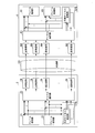
図2は、本実施形態の第1の適用例を示す概略図である。同図(a)は初期状態を示し、同図(b)は障害状態を示す。本図では、初期状態(a)から開始し、途中の所定の時点で障害が発生することにより、障害状態(b)に移行することを想定している。図示する構成において、伝送路区間におけるクロスコネクト部106は、送受信部24と、その出力先の方路との接続関係を制御する。
(a)初期状態
図示するように、データチャネルおよび冗長チャネルを含む複数のクライアント信号は、チャネル選択部23に対して入力され、さらに送受信部24を介して伝送路101へ出力される。データチャネルに対する冗長チャネル数や、それらのチャネルのクライアント信号が送出される方路は、クライアント信号毎に異なっていてもよい。図示する例では、クライアント1とクライアント2が存在する。クライアント1に関しては、初期状態において、2つのデータチャネルおよび1つの冗長チャネルの信号が方路Aに対して出力される。クライアント2に関しては、同じく初期状態において、1つデータチャネルおよび2つの冗長チャネルの信号が方路Bに対して出力される。
図示するように、データチャネルおよび冗長チャネルを含む複数のクライアント信号は、チャネル選択部23に対して入力され、さらに送受信部24を介して伝送路101へ出力される。データチャネルに対する冗長チャネル数や、それらのチャネルのクライアント信号が送出される方路は、クライアント信号毎に異なっていてもよい。図示する例では、クライアント1とクライアント2が存在する。クライアント1に関しては、初期状態において、2つのデータチャネルおよび1つの冗長チャネルの信号が方路Aに対して出力される。クライアント2に関しては、同じく初期状態において、1つデータチャネルおよび2つの冗長チャネルの信号が方路Bに対して出力される。
(b)障害状態
ここで、方路Aに出力していたクライアント1のデータチャネルまたは冗長チャネルのうち1チャネルの送受信部に障害が発生する場合を仮定する。クライアント1は1つの冗長チャネルを持っている。したがって、受信側の通信ノード装置2で障害発生を検出し、障害の発生したチャネルがデータチャネルであった場合は、受信側の冗長チャネル処理部62によって障害の発生した信号を、瞬断を発生させることなく正常に復元することができる。この時点で、クライアント1の冗長チャネル数が0になる。しかしながら、チャネル選択部23は、クライアント2側で冗長チャネルに割り当てていた送受信部24をクライアント1に割り当て直す。さらに、それに合わせて、クロスコネクト部106の接続関係を変更する。即ち、クライアント2からクライアント1に割り当てなおした送受信部24に対応する割当先を、方路Bから方路Aに変更するよう制御する。このことにより、クライアント1および2の双方にそれぞれ少なくとも1チャネル分の冗長チャネルを確保することができる。
ここで、方路Aに出力していたクライアント1のデータチャネルまたは冗長チャネルのうち1チャネルの送受信部に障害が発生する場合を仮定する。クライアント1は1つの冗長チャネルを持っている。したがって、受信側の通信ノード装置2で障害発生を検出し、障害の発生したチャネルがデータチャネルであった場合は、受信側の冗長チャネル処理部62によって障害の発生した信号を、瞬断を発生させることなく正常に復元することができる。この時点で、クライアント1の冗長チャネル数が0になる。しかしながら、チャネル選択部23は、クライアント2側で冗長チャネルに割り当てていた送受信部24をクライアント1に割り当て直す。さらに、それに合わせて、クロスコネクト部106の接続関係を変更する。即ち、クライアント2からクライアント1に割り当てなおした送受信部24に対応する割当先を、方路Bから方路Aに変更するよう制御する。このことにより、クライアント1および2の双方にそれぞれ少なくとも1チャネル分の冗長チャネルを確保することができる。
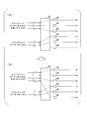
図3は、本実施形態の第2の適用例を示す概略図である。同図に示す例では、方路が同一である2つのクライアントがチャネル選択部23に接続されている。同図(a)は初期状態を示し、同図(b)は遷移先状態を示す。本図では、初期状態(a)から開始し、途中の所定の時点でクライアント1の信頼性を向上させる要求が発生することにより、遷移先状態(b)に移行することを想定している。
(a)初期状態
初期状態において、クライアント1は、2チャネルのデータチャネルと1チャネルの冗長チャネルとを持つ。また、初期状態において、クライアント2は、2チャネルのデータチャネルのみを持つ。また、初期状態において、通信ノード装置1は、1つの送受信部24(同図(a)における最も下の送受信部24)を空きリソースとして持つ。
(b)遷移先状態
ここで、クライアント1の信頼性を上げる要求が発生した場合、当該要求を満たすために、空きリソースとなっていた送受信部24を利用することができる。つまり、チャネル選択部23は、空きリソースであった送受信部24を、クライアント1に割り当てるように変更する。これにより、クライアント1が利用するチャネル数が増え、クライアント1に関する通信の信頼性が向上する。
初期状態において、クライアント1は、2チャネルのデータチャネルと1チャネルの冗長チャネルとを持つ。また、初期状態において、クライアント2は、2チャネルのデータチャネルのみを持つ。また、初期状態において、通信ノード装置1は、1つの送受信部24(同図(a)における最も下の送受信部24)を空きリソースとして持つ。
(b)遷移先状態
ここで、クライアント1の信頼性を上げる要求が発生した場合、当該要求を満たすために、空きリソースとなっていた送受信部24を利用することができる。つまり、チャネル選択部23は、空きリソースであった送受信部24を、クライアント1に割り当てるように変更する。これにより、クライアント1が利用するチャネル数が増え、クライアント1に関する通信の信頼性が向上する。
このように、チャネル選択部23がデータチャネルおよび冗長チャネルを切り替えることにより、未割当の送受信部を、方路がそれぞれ異なる任意のクライアントに対する障害復旧や信頼性の向上などの用途に適用することができる。
[第2実施形態]
次に、第2実施形態について説明する。なお、前実施形態において既に説明した事項については以下において説明を省略する場合がある。ここでは、本実施形態に特有の事項を中心に説明する。第1実施形態では、通信ノード装置1において、各フレーム処理部21に対して1つの冗長チャネル処理部22が設けられていた。また、通信ノード装置2において、各フレーム処理部61に対して1つの冗長チャネル処理部62が設けられていた。
そして、第1実施形態では、各クライアント信号を収容するフレーム処理部21に対して設定可能な冗長チャネル数の上限値が、冗長チャネル処理部22によって決定されていた。これに対し、本実施形態では、送信側の通信ノード装置3において、複数の冗長チャネル処理部27からなる冗長チャネル処理群27Gが、複数のフレーム処理部21によって共有される構成となっている。また、本実施形態では、受信側の通信ノード装置4において、複数の冗長チャネル処理部67からなる冗長チャネル処理群67Gが、複数のフレーム処理部61によって共有される構成となっている。
次に、第2実施形態について説明する。なお、前実施形態において既に説明した事項については以下において説明を省略する場合がある。ここでは、本実施形態に特有の事項を中心に説明する。第1実施形態では、通信ノード装置1において、各フレーム処理部21に対して1つの冗長チャネル処理部22が設けられていた。また、通信ノード装置2において、各フレーム処理部61に対して1つの冗長チャネル処理部62が設けられていた。
そして、第1実施形態では、各クライアント信号を収容するフレーム処理部21に対して設定可能な冗長チャネル数の上限値が、冗長チャネル処理部22によって決定されていた。これに対し、本実施形態では、送信側の通信ノード装置3において、複数の冗長チャネル処理部27からなる冗長チャネル処理群27Gが、複数のフレーム処理部21によって共有される構成となっている。また、本実施形態では、受信側の通信ノード装置4において、複数の冗長チャネル処理部67からなる冗長チャネル処理群67Gが、複数のフレーム処理部61によって共有される構成となっている。
図4は、第2実施形態による伝送システムの概略機能構成を示すブロック図である。図示するように、この伝送システムは、伝送路101と、その端点における通信ノード装置3および4とを含んで構成される。通信ノード装置3は送信側の通信ノード装置(送信装置)であり、通信ノード装置4は受信側の通信ノード装置(受信装置)である。同図では信号の流れを片方向(通信ノード装置1から通信ノード装置2への方向)のみ示しているが、通信ノード装置が送信側と受信側の両方の機能を備えることにより、双方向の通信も容易に実現可能である。
送信側である通信ノード装置3は、複数のフレーム処理部21と、複数の冗長チャネル処理部27からなる冗長チャネル処理群27Gと、チャネル選択部23と、複数の送受信部24とを含んで構成される。
受信側である通信ノード装置4は、複数のフレーム処理部61と、複数の冗長チャネル処理部67からなる冗長チャネル処理群67Gと、チャネル選択部63と、複数の送受信部64とを含んで構成される。
受信側である通信ノード装置4は、複数のフレーム処理部61と、複数の冗長チャネル処理部67からなる冗長チャネル処理群67Gと、チャネル選択部63と、複数の送受信部64とを含んで構成される。
冗長チャネル処理群27Gは、1以上の冗長チャネル処理部27を有する。冗長チャネル処理群27Gは、2以上のフレーム処理部21によって共有される。冗長チャネル処理群27Gは、任意のフレーム処理部21が出力した分割フレームを基に、冗長チャネル処理群27Gが生成可能な冗長フレーム数を上限とした数の冗長フレームを生成する。
冗長チャネル処理群27Gは、各々のフレーム処理部21から複製されたフレームがどの冗長チャネル処理部27に収容されるかを選択する機能を持つ。この構成により、単一のフレーム処理部21から生成可能な冗長チャネル数は、最大で、(1つの冗長チャネル処理部27で生成可能な冗長チャネル数)×(冗長チャネル処理部27の数)となる。つまり、第1実施形態の場合と比較して、本実施形態では、大幅に増加したチャネルの冗長性を確保することが可能となる。また、さらに、複数のクライアント間で冗長チャネル数を融通し合うことにより、第1実施形態の場合と比較して、冗長チャネル処理部27の効率的な利用が可能になる。
冗長チャネル処理群27Gは、各々のフレーム処理部21から複製されたフレームがどの冗長チャネル処理部27に収容されるかを選択する機能を持つ。この構成により、単一のフレーム処理部21から生成可能な冗長チャネル数は、最大で、(1つの冗長チャネル処理部27で生成可能な冗長チャネル数)×(冗長チャネル処理部27の数)となる。つまり、第1実施形態の場合と比較して、本実施形態では、大幅に増加したチャネルの冗長性を確保することが可能となる。また、さらに、複数のクライアント間で冗長チャネル数を融通し合うことにより、第1実施形態の場合と比較して、冗長チャネル処理部27の効率的な利用が可能になる。
その他の点については、本実施形態の機能、動作は、第1実施形態のそれらと同様である。
[第3実施形態]
次に、第3実施形態について説明する。なお、前実施形態までにおいて既に説明した事項については以下において説明を省略する場合がある。ここでは、本実施形態に特有の事項を中心に説明する。第3実施形態の特徴は、遠隔地に配置したオペレーションシステムが、通信ノード装置におけるフレーム処理部から送出される分割フレームに対して、データチャネル処理部から送出される冗長チャネル数と、チャネル選択部にて選択される送受信部とを、設定・制御する点である。
次に、第3実施形態について説明する。なお、前実施形態までにおいて既に説明した事項については以下において説明を省略する場合がある。ここでは、本実施形態に特有の事項を中心に説明する。第3実施形態の特徴は、遠隔地に配置したオペレーションシステムが、通信ノード装置におけるフレーム処理部から送出される分割フレームに対して、データチャネル処理部から送出される冗長チャネル数と、チャネル選択部にて選択される送受信部とを、設定・制御する点である。
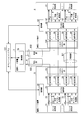
図5は、第3実施形態による伝送システムの概略機能構成を示すブロック図である。図示するように、この伝送システムは、伝送路101,102,103と、それらの伝送路の端点に配した通信ノード装置5,6,7と、オペレーションシステム121とを含んで構成される。伝送路101は、通信ノード装置5と通信ノード装置6とを直接結ぶ伝送路である。伝送路102は、通信ノード装置5と通信ノード装置7とを直接結ぶ伝送路である。伝送路103は、通信ノード装置7と通信ノード装置6とを直接結ぶ伝送路である。
通信ノード装置5は送信側の通信ノード装置(送信装置)であり、通信ノード装置6は受信側の通信ノード装置(受信装置)である。
通信ノード装置5は送信側の通信ノード装置(送信装置)であり、通信ノード装置6は受信側の通信ノード装置(受信装置)である。
本実施形態では、通信ノード装置7は、通信ノード装置5から通信ノード装置6へのデータの伝送を中継する役割を持つ。言い換えれば、通信ノード装置5から通信ノード装置6への経路としては、伝送路101を経由する経路と、伝送路102と通信ノード装置7と伝送路103とを経由する経路とが存在する。
送信側である通信ノード装置5は、複数のフレーム処理部21と、複数の冗長チャネル処理部22と、チャネル選択部23と、複数の送受信部24と、制御部28と、クロスコネクト部107とを含んで構成される。
受信側である通信ノード装置6は、複数のフレーム処理部61と、複数の冗長チャネル処理部62と、チャネル選択部63と、複数の送受信部64と、制御部68と、クロスコネクト部108とを含んで構成される。
また、通信ノード装置7は、通信ノード装置5が有する送信装置としての機能と、通信ノード装置6が有する受信装置としての機能を備える。また、通信ノード装置7もまた、制御部78を含んで構成される。
受信側である通信ノード装置6は、複数のフレーム処理部61と、複数の冗長チャネル処理部62と、チャネル選択部63と、複数の送受信部64と、制御部68と、クロスコネクト部108とを含んで構成される。
また、通信ノード装置7は、通信ノード装置5が有する送信装置としての機能と、通信ノード装置6が有する受信装置としての機能を備える。また、通信ノード装置7もまた、制御部78を含んで構成される。
通信ノード装置5内のクロスコネクト部107は、複数の送受信部24の各々について、伝送路の方路別の接続を制御する。
また、通信ノード装置6内のクロスコネクト部108は、複数の送受信部64の各々について、方路別の接続を制御する。
また、通信ノード装置6内のクロスコネクト部108は、複数の送受信部64の各々について、方路別の接続を制御する。
本実施形態の特徴は、通信ノード装置5が制御部28を有し、通信ノード装置6が制御部68を有し、通信ノード装置7が制御部78を有する点である。また、本実施形態に特有のオペレーションシステム121は、上記の制御部28,68,78のそれぞれとの間で双方向の通信を行う。オペレーションシステム121は、通信ノード装置5,6,7のそれぞれから遠隔の地に設置されていてもよい。オペレーションシステム121は、制御部28,68,78を介して、それぞれ、通信ノード装置5,6,7を制御する。その制御の具体的な内容は、次の通りである。
通信ノード装置5,6,7の、それぞれ、制御部28,68,78は、データチャネルの異常が検出された場合にはその異常をオペレーションシステム121に通知する。
オペレーションシステム121は、制御部28.68.78から通知されるデータチャネルの異常の情報を受信する。また、オペレーションシステム121は、フレーム処理部の新規設定や、帯域増速あるいは帯域減速や、冗長度向上などの需要に関する情報を外部から(例えば、オペレーションシステム121のユーザーインターフェースなどを介して)取得する。オペレーションシステム121は、上記の、データチャネルの異常通知や、フレーム処理部の新規設定や、帯域増速あるいは帯域減速や、冗長度向上の需要などに基づいて、分割フレームまたは冗長フレームの割り当て先となる送受信部を決定し、チャネル選択部での振り分け先を設定する。オペレーションシステム121によるこの設定は、通信ノード装置5,6,7の、それぞれ、制御部28,68,78に伝えられ、通信ノード装置側での設定が行われる。
オペレーションシステム121は、制御部28.68.78から通知されるデータチャネルの異常の情報を受信する。また、オペレーションシステム121は、フレーム処理部の新規設定や、帯域増速あるいは帯域減速や、冗長度向上などの需要に関する情報を外部から(例えば、オペレーションシステム121のユーザーインターフェースなどを介して)取得する。オペレーションシステム121は、上記の、データチャネルの異常通知や、フレーム処理部の新規設定や、帯域増速あるいは帯域減速や、冗長度向上の需要などに基づいて、分割フレームまたは冗長フレームの割り当て先となる送受信部を決定し、チャネル選択部での振り分け先を設定する。オペレーションシステム121によるこの設定は、通信ノード装置5,6,7の、それぞれ、制御部28,68,78に伝えられ、通信ノード装置側での設定が行われる。
つまりオペレーションシステム121は、送信側の通信ノード装置におけるフレーム処理部から送出される分割フレームに対して、送信側の通信ノード装置におけるデータチャネル処理部から送出される冗長チャネル数と、送信側の通信ノード装置におけるチャネル選択部にて選択される送受信部とを、制御・設定するものである。
[第3実施形態の変形例]
なお、変形例として、本実施形態と、第2実施形態とを組み合わせて実施するようにしてもよい。言い換えれば、本実施形態において、通信ノード装置が冗長チャネル処理群を備えるようにする。即ち、各通信ノード装置は、図4に示した通信ノード装置3や通信ノード装置4と同様に、冗長チャネル処理群(27G,67G)を備える。また、各通信ノード装置は、図5に示した通信ノード装置5や通信ノード装置6や通信ノード装置7と同様に、制御部(28,68,78)を備える。そして、オペレーションシステム121は、各通信ノード装置の制御部を介して、各フレーム処理部によって生成された分割フレームをどの冗長チャネル処理部に割り当てるかを制御する。
なお、変形例として、本実施形態と、第2実施形態とを組み合わせて実施するようにしてもよい。言い換えれば、本実施形態において、通信ノード装置が冗長チャネル処理群を備えるようにする。即ち、各通信ノード装置は、図4に示した通信ノード装置3や通信ノード装置4と同様に、冗長チャネル処理群(27G,67G)を備える。また、各通信ノード装置は、図5に示した通信ノード装置5や通信ノード装置6や通信ノード装置7と同様に、制御部(28,68,78)を備える。そして、オペレーションシステム121は、各通信ノード装置の制御部を介して、各フレーム処理部によって生成された分割フレームをどの冗長チャネル処理部に割り当てるかを制御する。
本実施形態およびその変形例によれば、オペレーションシステム121が制御機能を備え、各通信ノード装置に関する各種設定、制御を行う。オペレーションシステム121は通信ノード装置とは遠隔の地に設けられていてよい。これにより、複数チャネルから構成される冗長システムを容易に構成することが可能となる。
なお、上述した各実施形態および変形例における通信ノード装置およびオペレーションシステムの少なくとも一部の機能をコンピューターで実現することができる。その場合、この機能を実現するためのプログラムをコンピューター読み取り可能な記録媒体に記録して、この記録媒体に記録されたプログラムをコンピューターシステムに読み込ませ、実行することによって実現しても良い。なお、ここでいう「コンピューターシステム」とは、OSや周辺機器等のハードウェアを含むものとする。また、「コンピューター読み取り可能な記録媒体」とは、フレキシブルディスク、光磁気ディスク、ROM、CD-ROM、DVD-ROM、USBメモリー等の可搬媒体、コンピューターシステムに内蔵されるハードディスク等の記憶装置のことをいう。さらに「コンピューター読み取り可能な記録媒体」とは、インターネット等のネットワークや電話回線等の通信回線を介してプログラムを送信する場合の通信線のように、一時的に、動的にプログラムを保持するもの、その場合のサーバーやクライアントとなるコンピューターシステム内部の揮発性メモリーのように、一定時間プログラムを保持しているものも含んでも良い。また上記プログラムは、前述した機能の一部を実現するためのものであっても良く、さらに前述した機能をコンピューターシステムにすでに記録されているプログラムとの組み合わせで実現できるものであっても良い。
以上、この発明の実施形態について図面を参照して詳述してきたが、具体的な構成はこの実施形態に限られるものではなく、この発明の要旨を逸脱しない範囲の設計等も含まれる。
本発明は、例えば、データの通信のために利用することができる。但し、本発明の利用範囲はここに例示したものには限られない。
1,3,5 通信ノード装置(送信装置)
2,4,6 通信ノード装置(受信装置)
7 通信ノード装置
21 フレーム処理部
22 冗長チャネル処理部
23 チャネル選択部
24 送受信部
27 冗長チャネル処理部
27G 冗長チャネル処理群
28 制御部
61 フレーム処理部
62 冗長チャネル処理部
63 チャネル選択部
64 送受信部
67 冗長チャネル処理部
67G 冗長チャネル処理群
68,78 制御部
101,102,103 伝送路
106,107,108 クロスコネクト部
121 オペレーションシステム
2,4,6 通信ノード装置(受信装置)
7 通信ノード装置
21 フレーム処理部
22 冗長チャネル処理部
23 チャネル選択部
24 送受信部
27 冗長チャネル処理部
27G 冗長チャネル処理群
28 制御部
61 フレーム処理部
62 冗長チャネル処理部
63 チャネル選択部
64 送受信部
67 冗長チャネル処理部
67G 冗長チャネル処理群
68,78 制御部
101,102,103 伝送路
106,107,108 クロスコネクト部
121 オペレーションシステム
Claims (4)
- フレームを1以上に分割して分割フレームを生成し、生成した前記分割フレームのそれぞれに誤り検出信号を付加し、誤り検出信号を付加した前記分割フレームを複数のデータチャネルに出力するフレーム処理部と、
前記分割フレームの誤りが検出された際に前記分割フレームの復元を可能とする復元情報を含む1以上の冗長フレームを前記分割フレームから生成してデータチャネルに出力する冗長チャネル処理部と、
前記フレーム処理部から出力された前記分割フレーム、および前記冗長チャネル処理部から出力された前記冗長フレームを、伝送路に出力する送受信部と、
前記分割フレームおよび前記冗長フレームを、それぞれ割り当て可能な前記送受信部に割り当てるチャネル選択部と、
を備える送信装置。 - 1以上の前記冗長チャネル処理部を有する冗長チャネル処理群、
を備え、
2以上の前記フレーム処理部が、前記冗長チャネル処理群を共有し、
前記冗長チャネル処理群は、任意の前記フレーム処理部が出力した前記分割フレームを基に、前記冗長チャネル処理群が生成可能な冗長フレーム数を上限とした数の冗長フレームを生成する、
請求項1に記載の送信装置。 - フレームを1以上に分割し且つ誤り検出符号を付加することによって生成された分割フレームを、または前記分割フレームの伝送エラー時に前記分割フレームの復元を可能とする復元情報を含むよう生成された冗長フレームを、伝送路から入力する送受信部と、
前記送受信部から渡される前記分割フレームに付加された前記誤り検出符号により誤り検出の処理を行うとともに、誤りが検出されなかった場合には当該分割フレームに基づき、また誤りが検出された場合には前記冗長フレームを用いて復元された前記分割フレームに基づき、前記フレームを出力するフレーム処理部と、
前記フレーム処理部が前記誤り検出符号に基づいて誤りを検出した場合に、前記冗長フレームに含まれる復元情報と、異常が検出されなかったデータチャネルの前記分割フレームとに基づいて、異常が検出されたデータチャネルの分割フレームを復元する冗長チャネル処理部と、
を備える受信装置。 - 請求項1または2に記載の送信装置と、
請求項3に記載の受信装置と、
前記送信装置における前記フレーム処理部から送出される分割フレームに対して、前記送信装置における前記冗長チャネル処理部から送出される冗長チャネル数と、前記送信装置における前記チャネル選択部にて選択される送受信部とを、設定するオペレーションシステムと、
を有する伝送システム。
Priority Applications (1)
| Application Number | Priority Date | Filing Date | Title |
|---|---|---|---|
| US17/257,759 US11581988B2 (en) | 2018-07-06 | 2019-06-24 | Transmitting apparatus, receiving apparatus, and transmission system |
Applications Claiming Priority (2)
| Application Number | Priority Date | Filing Date | Title |
|---|---|---|---|
| JP2018-129373 | 2018-07-06 | ||
| JP2018129373A JP2020010180A (ja) | 2018-07-06 | 2018-07-06 | 送信装置、受信装置、および伝送システム |
Publications (1)
| Publication Number | Publication Date |
|---|---|
| WO2020008929A1 true WO2020008929A1 (ja) | 2020-01-09 |
Family
ID=69059621
Family Applications (1)
| Application Number | Title | Priority Date | Filing Date |
|---|---|---|---|
| PCT/JP2019/024887 Ceased WO2020008929A1 (ja) | 2018-07-06 | 2019-06-24 | 送信装置、受信装置、および伝送システム |
Country Status (3)
| Country | Link |
|---|---|
| US (1) | US11581988B2 (ja) |
| JP (1) | JP2020010180A (ja) |
| WO (1) | WO2020008929A1 (ja) |
Families Citing this family (1)
| Publication number | Priority date | Publication date | Assignee | Title |
|---|---|---|---|---|
| JP7521582B2 (ja) * | 2020-07-13 | 2024-07-24 | 日本電信電話株式会社 | 送信側伝送装置、受信側伝送装置、送信側伝送装置の冗長化方法、受信側伝送装置の冗長化方法、プログラム、及び伝送装置 |
Citations (7)
| Publication number | Priority date | Publication date | Assignee | Title |
|---|---|---|---|---|
| US20030229844A1 (en) * | 2002-03-25 | 2003-12-11 | Akash Bansal | Graceful degradation of serial channels |
| JP2006186527A (ja) * | 2004-12-27 | 2006-07-13 | Nec Computertechno Ltd | データ伝送方式及び方法 |
| JP2010161673A (ja) * | 2009-01-09 | 2010-07-22 | National Institute Of Information & Communication Technology | 無線通信システム及び方法 |
| JP2014017637A (ja) * | 2012-07-09 | 2014-01-30 | Nippon Telegr & Teleph Corp <Ntt> | 送受信制御装置、送受信制御方法及び送受信制御プログラム |
| WO2014045906A1 (ja) * | 2012-09-21 | 2014-03-27 | 日本電信電話株式会社 | 並列データ符号復号化システム |
| JP2016103762A (ja) * | 2014-11-28 | 2016-06-02 | 日本電信電話株式会社 | 光伝送システム及び光伝送方法 |
| JP2016208190A (ja) * | 2015-04-20 | 2016-12-08 | 日本電信電話株式会社 | 通信装置及び通信方法 |
Family Cites Families (8)
| Publication number | Priority date | Publication date | Assignee | Title |
|---|---|---|---|---|
| JP3877576B2 (ja) * | 2001-11-07 | 2007-02-07 | 沖電気工業株式会社 | 並列送信装置及び並列伝送システム |
| JP2009159440A (ja) * | 2007-12-27 | 2009-07-16 | Kyocera Corp | 通信装置、通信システムおよび通信方法 |
| JP5610709B2 (ja) * | 2009-06-04 | 2014-10-22 | キヤノン株式会社 | エラー訂正用データの生成装置、及び生成方法 |
| JP5398907B2 (ja) * | 2010-04-23 | 2014-01-29 | 三菱電機株式会社 | 光通信システム |
| US20120082448A1 (en) * | 2010-09-30 | 2012-04-05 | Fujitsu Limited | System and method for sparing channels of a multi-wavelength transponder |
| WO2013005766A1 (ja) * | 2011-07-04 | 2013-01-10 | 日本電信電話株式会社 | 伝送システム及び伝送方法 |
| WO2015194217A1 (ja) * | 2014-06-20 | 2015-12-23 | 日本電気株式会社 | 通信装置、通信方法、プログラム及び通信システム |
| WO2019053296A1 (de) * | 2017-09-18 | 2019-03-21 | Osram Gmbh | Verfahren zur linearen kodierung von signalen für die redundante übertragung von daten über mehrere optische kanäle |
-
2018
- 2018-07-06 JP JP2018129373A patent/JP2020010180A/ja active Pending
-
2019
- 2019-06-24 WO PCT/JP2019/024887 patent/WO2020008929A1/ja not_active Ceased
- 2019-06-24 US US17/257,759 patent/US11581988B2/en active Active
Patent Citations (7)
| Publication number | Priority date | Publication date | Assignee | Title |
|---|---|---|---|---|
| US20030229844A1 (en) * | 2002-03-25 | 2003-12-11 | Akash Bansal | Graceful degradation of serial channels |
| JP2006186527A (ja) * | 2004-12-27 | 2006-07-13 | Nec Computertechno Ltd | データ伝送方式及び方法 |
| JP2010161673A (ja) * | 2009-01-09 | 2010-07-22 | National Institute Of Information & Communication Technology | 無線通信システム及び方法 |
| JP2014017637A (ja) * | 2012-07-09 | 2014-01-30 | Nippon Telegr & Teleph Corp <Ntt> | 送受信制御装置、送受信制御方法及び送受信制御プログラム |
| WO2014045906A1 (ja) * | 2012-09-21 | 2014-03-27 | 日本電信電話株式会社 | 並列データ符号復号化システム |
| JP2016103762A (ja) * | 2014-11-28 | 2016-06-02 | 日本電信電話株式会社 | 光伝送システム及び光伝送方法 |
| JP2016208190A (ja) * | 2015-04-20 | 2016-12-08 | 日本電信電話株式会社 | 通信装置及び通信方法 |
Also Published As
| Publication number | Publication date |
|---|---|
| US20210160017A1 (en) | 2021-05-27 |
| JP2020010180A (ja) | 2020-01-16 |
| US11581988B2 (en) | 2023-02-14 |
Similar Documents
| Publication | Publication Date | Title |
|---|---|---|
| JP6536586B2 (ja) | 光通信システム、光ノード装置、および光パス設定方法 | |
| US20120281525A1 (en) | METHOD AND SYSTEM FOR PRIORITY BASED (1:1)n ETHERNET PROTECTION | |
| EP3618350B1 (en) | Protection switching method, device and system | |
| US20140372601A1 (en) | Monitoring apparatus and monitoring method | |
| JP6135226B2 (ja) | 情報処理装置、情報処理方法、ストレージシステム及びコンピュータプログラム | |
| JP2009010441A (ja) | インタフェース切替方法および装置 | |
| JPWO2019188635A1 (ja) | 光トランスポンダ | |
| JP4078670B2 (ja) | データ伝送方法及び装置 | |
| GB2128782A (en) | Data processing systems | |
| US11581988B2 (en) | Transmitting apparatus, receiving apparatus, and transmission system | |
| JP4036652B2 (ja) | リング制御ノード | |
| JP5471652B2 (ja) | 通信ノード装置、通信システム及びそれらに用いる宛先受信インタフェース選択方法 | |
| CN111263250B (zh) | 业务数据处理方法及设备 | |
| JP6082357B2 (ja) | 通信システム及び冗長構成設定方法 | |
| JP7327638B2 (ja) | 通信システム、送信装置、受信装置、通信方法及びプログラム | |
| KR102251407B1 (ko) | 소프트웨어 정의 네트워크에서 컨트롤러의 이중화 제어 시스템 및 그 방법 | |
| JP7248267B2 (ja) | ストレージ装置、復旧方法、プログラム | |
| JP2017085309A (ja) | リング型光アクセスネットワークシステム、局側装置、加入者側装置、局側光スイッチ、加入者側光スイッチ、コントローラ、光通信方法 | |
| JP5644226B2 (ja) | 冗長ペア、信号伝送方法およびプログラム | |
| JP2014017637A (ja) | 送受信制御装置、送受信制御方法及び送受信制御プログラム | |
| JP2867865B2 (ja) | 予備回線切替制御方式 | |
| Cho | Trade-off between Resource Efficiency and Fast Protection for Shared Mesh Protection | |
| WO2023233666A1 (ja) | 無瞬断冗長切替装置、無瞬断冗長切替方法、無瞬断冗長切替システム、及びプログラム | |
| JP6408500B2 (ja) | 呼処理システム、負荷分散装置及び負荷分散方法 | |
| WO2023188860A1 (ja) | 分散システムおよび分散システムにおける通信経路作成方法 |
Legal Events
| Date | Code | Title | Description |
|---|---|---|---|
| 121 | Ep: the epo has been informed by wipo that ep was designated in this application |
Ref document number: 19830863 Country of ref document: EP Kind code of ref document: A1 |
|
| NENP | Non-entry into the national phase |
Ref country code: DE |
|
| 122 | Ep: pct application non-entry in european phase |
Ref document number: 19830863 Country of ref document: EP Kind code of ref document: A1 |