WO2020008659A1 - Ligne de production et procédé de fabrication de ligne de production - Google Patents
Ligne de production et procédé de fabrication de ligne de production Download PDFInfo
- Publication number
- WO2020008659A1 WO2020008659A1 PCT/JP2018/037037 JP2018037037W WO2020008659A1 WO 2020008659 A1 WO2020008659 A1 WO 2020008659A1 JP 2018037037 W JP2018037037 W JP 2018037037W WO 2020008659 A1 WO2020008659 A1 WO 2020008659A1
- Authority
- WO
- WIPO (PCT)
- Prior art keywords
- cell
- work
- production line
- pallet
- conveyor
- Prior art date
Links
- 238000004519 manufacturing process Methods 0.000 title claims abstract description 142
- 230000008439 repair process Effects 0.000 claims abstract description 40
- 230000032258 transport Effects 0.000 claims description 170
- 230000007246 mechanism Effects 0.000 claims description 69
- 238000011144 upstream manufacturing Methods 0.000 claims description 39
- 238000000034 method Methods 0.000 claims description 31
- 230000008569 process Effects 0.000 claims description 24
- 238000012546 transfer Methods 0.000 claims description 23
- 238000007599 discharging Methods 0.000 claims description 13
- 239000011265 semifinished product Substances 0.000 description 51
- 230000003028 elevating effect Effects 0.000 description 22
- 239000000047 product Substances 0.000 description 21
- 230000002950 deficient Effects 0.000 description 15
- 239000000758 substrate Substances 0.000 description 14
- 238000012423 maintenance Methods 0.000 description 9
- 238000010586 diagram Methods 0.000 description 7
- 230000006872 improvement Effects 0.000 description 7
- 230000007547 defect Effects 0.000 description 6
- 238000001514 detection method Methods 0.000 description 6
- 238000004891 communication Methods 0.000 description 4
- 230000004048 modification Effects 0.000 description 4
- 238000012986 modification Methods 0.000 description 4
- 230000008859 change Effects 0.000 description 3
- 238000005192 partition Methods 0.000 description 2
- 238000004904 shortening Methods 0.000 description 2
- 150000001875 compounds Chemical class 0.000 description 1
- 238000011161 development Methods 0.000 description 1
- 230000000694 effects Effects 0.000 description 1
- NJPPVKZQTLUDBO-UHFFFAOYSA-N novaluron Chemical compound C1=C(Cl)C(OC(F)(F)C(OC(F)(F)F)F)=CC=C1NC(=O)NC(=O)C1=C(F)C=CC=C1F NJPPVKZQTLUDBO-UHFFFAOYSA-N 0.000 description 1
- 230000003287 optical effect Effects 0.000 description 1
- 238000012545 processing Methods 0.000 description 1
- 239000004065 semiconductor Substances 0.000 description 1
- 239000013589 supplement Substances 0.000 description 1
- 238000011179 visual inspection Methods 0.000 description 1
Images


Classifications
-
- B—PERFORMING OPERATIONS; TRANSPORTING
- B23—MACHINE TOOLS; METAL-WORKING NOT OTHERWISE PROVIDED FOR
- B23P—METAL-WORKING NOT OTHERWISE PROVIDED FOR; COMBINED OPERATIONS; UNIVERSAL MACHINE TOOLS
- B23P21/00—Machines for assembling a multiplicity of different parts to compose units, with or without preceding or subsequent working of such parts, e.g. with programme control
- B23P21/004—Machines for assembling a multiplicity of different parts to compose units, with or without preceding or subsequent working of such parts, e.g. with programme control the units passing two or more work-stations whilst being composed
-
- B—PERFORMING OPERATIONS; TRANSPORTING
- B23—MACHINE TOOLS; METAL-WORKING NOT OTHERWISE PROVIDED FOR
- B23Q—DETAILS, COMPONENTS, OR ACCESSORIES FOR MACHINE TOOLS, e.g. ARRANGEMENTS FOR COPYING OR CONTROLLING; MACHINE TOOLS IN GENERAL CHARACTERISED BY THE CONSTRUCTION OF PARTICULAR DETAILS OR COMPONENTS; COMBINATIONS OR ASSOCIATIONS OF METAL-WORKING MACHINES, NOT DIRECTED TO A PARTICULAR RESULT
- B23Q7/00—Arrangements for handling work specially combined with or arranged in, or specially adapted for use in connection with, machine tools, e.g. for conveying, loading, positioning, discharging, sorting
- B23Q7/14—Arrangements for handling work specially combined with or arranged in, or specially adapted for use in connection with, machine tools, e.g. for conveying, loading, positioning, discharging, sorting co-ordinated in production lines
-
- B—PERFORMING OPERATIONS; TRANSPORTING
- B25—HAND TOOLS; PORTABLE POWER-DRIVEN TOOLS; MANIPULATORS
- B25J—MANIPULATORS; CHAMBERS PROVIDED WITH MANIPULATION DEVICES
- B25J21/00—Chambers provided with manipulation devices
-
- B—PERFORMING OPERATIONS; TRANSPORTING
- B25—HAND TOOLS; PORTABLE POWER-DRIVEN TOOLS; MANIPULATORS
- B25J—MANIPULATORS; CHAMBERS PROVIDED WITH MANIPULATION DEVICES
- B25J9/00—Programme-controlled manipulators
- B25J9/0084—Programme-controlled manipulators comprising a plurality of manipulators
-
- B—PERFORMING OPERATIONS; TRANSPORTING
- B25—HAND TOOLS; PORTABLE POWER-DRIVEN TOOLS; MANIPULATORS
- B25J—MANIPULATORS; CHAMBERS PROVIDED WITH MANIPULATION DEVICES
- B25J9/00—Programme-controlled manipulators
- B25J9/0093—Programme-controlled manipulators co-operating with conveyor means
-
- G—PHYSICS
- G05—CONTROLLING; REGULATING
- G05B—CONTROL OR REGULATING SYSTEMS IN GENERAL; FUNCTIONAL ELEMENTS OF SUCH SYSTEMS; MONITORING OR TESTING ARRANGEMENTS FOR SUCH SYSTEMS OR ELEMENTS
- G05B19/00—Programme-control systems
- G05B19/02—Programme-control systems electric
- G05B19/418—Total factory control, i.e. centrally controlling a plurality of machines, e.g. direct or distributed numerical control [DNC], flexible manufacturing systems [FMS], integrated manufacturing systems [IMS] or computer integrated manufacturing [CIM]
- G05B19/41865—Total factory control, i.e. centrally controlling a plurality of machines, e.g. direct or distributed numerical control [DNC], flexible manufacturing systems [FMS], integrated manufacturing systems [IMS] or computer integrated manufacturing [CIM] characterised by job scheduling, process planning, material flow
-
- B—PERFORMING OPERATIONS; TRANSPORTING
- B23—MACHINE TOOLS; METAL-WORKING NOT OTHERWISE PROVIDED FOR
- B23P—METAL-WORKING NOT OTHERWISE PROVIDED FOR; COMBINED OPERATIONS; UNIVERSAL MACHINE TOOLS
- B23P2700/00—Indexing scheme relating to the articles being treated, e.g. manufactured, repaired, assembled, connected or other operations covered in the subgroups
- B23P2700/50—Other automobile vehicle parts, i.e. manufactured in assembly lines
-
- G—PHYSICS
- G05—CONTROLLING; REGULATING
- G05B—CONTROL OR REGULATING SYSTEMS IN GENERAL; FUNCTIONAL ELEMENTS OF SUCH SYSTEMS; MONITORING OR TESTING ARRANGEMENTS FOR SUCH SYSTEMS OR ELEMENTS
- G05B2219/00—Program-control systems
- G05B2219/30—Nc systems
- G05B2219/32—Operator till task planning
- G05B2219/32015—Optimize, process management, optimize production line
-
- Y—GENERAL TAGGING OF NEW TECHNOLOGICAL DEVELOPMENTS; GENERAL TAGGING OF CROSS-SECTIONAL TECHNOLOGIES SPANNING OVER SEVERAL SECTIONS OF THE IPC; TECHNICAL SUBJECTS COVERED BY FORMER USPC CROSS-REFERENCE ART COLLECTIONS [XRACs] AND DIGESTS
- Y02—TECHNOLOGIES OR APPLICATIONS FOR MITIGATION OR ADAPTATION AGAINST CLIMATE CHANGE
- Y02P—CLIMATE CHANGE MITIGATION TECHNOLOGIES IN THE PRODUCTION OR PROCESSING OF GOODS
- Y02P90/00—Enabling technologies with a potential contribution to greenhouse gas [GHG] emissions mitigation
- Y02P90/02—Total factory control, e.g. smart factories, flexible manufacturing systems [FMS] or integrated manufacturing systems [IMS]
Definitions
- the disclosed embodiments relate to a production line and a method of manufacturing the production line.
- Patent Document 1 discloses a first robot, a movable first cell provided with the first robot, a second robot, and a movable second cell provided with the second robot.
- a described robot system is described.
- the above-mentioned conventional robot system is used, for example, in a production line for producing products.
- a production line for producing products.
- high flexibility is demanded.
- the present invention has been made in view of such a problem, and an object of the present invention is to provide a production line and a method of manufacturing the production line that can realize high flexibility.
- a production line for producing a product configured by combining a plurality of cells, wherein the plurality of cells perform a predetermined operation on a part.
- a production line including at least one first cell provided with an automatic working machine for performing and at least one second cell arranged adjacent to the first cell and capable of performing repair or discharge of the part is applied. Is done.
- a production line for producing a product which is configured by combining a plurality of cells, wherein the plurality of cells includes an automatic working machine that performs a predetermined operation on a part. And at least one second cell disposed adjacent to the first cell and capable of performing repair or discharge of the component, wherein the first cell includes the automatic cell.
- a working machine at least one dedicated working machine designed exclusively for performing the predetermined work, and the parts between the pallet and the dedicated working machine, or between a plurality of the dedicated working machines. Moving at least one multi-joint type robot having a plurality of joints, and transporting the pallet on which the components are mounted in a first direction which is a transport direction of the components on the production line.
- a plurality of works each of which is a stop position for stopping the pallet conveyed by the first transfer device for a predetermined stop time, and each of which is assigned a predetermined work process executed by the dedicated work machine;
- a production line with stations is applied.
- a method for manufacturing a production line for producing a product which is configured by combining a plurality of cells, and performs a predetermined operation on a part based on the specification of the production line.
- a method of manufacturing a production line having the steps of:
- a production line for producing a product is configured by combining a plurality of cells, and each of the plurality of cells includes a pallet on which parts are placed.
- a production line is provided which has a conveying device for conveying, and at least one of the plurality of cells has an automatic working machine for performing a predetermined operation on the component.
- FIG. 3 is an explanatory diagram illustrating a configuration example of hardware of a controller.
- the right direction in the left-right direction refers to the direction in which the work is transported on the production line
- the up-down direction refers to the vertical direction
- the front-back direction refers to the direction perpendicular to both the left-right direction and the up-down direction.
- FIG. 1 is an explanatory diagram illustrating an example of an appearance of a production line
- FIG. 2 is an explanatory diagram illustrating an example of a pallet flow and an example of a controller configuration in the production line.
- the production line 1 is a production line for producing a product by combining a plurality of components while transporting the components in the transport direction, and is configured by combining a plurality of cells as shown in FIG.
- Each cell is assigned a predetermined work content.
- Each cell includes a housing for accommodating devices and the like for performing assigned work, and a plurality of casters 2 provided at a lower portion of the housing, and is configured to be movable.
- An adjuster is provided at the caster 2 or at a location different from the caster 2, and the height can be adjusted by leveling or the like.
- the production line 1 includes a connection cell 3, a first component supply cell 5, a connection cell 7, a first assembly cell 9, a connection cell 11, from the upstream side (left side) to the downstream side (right side) in the component transport direction.
- the second assembly cell 13, the connection cell 15, the second component supply cell 17, the connection cell 19, the third assembly cell 21, the connection cell 23, the third component supply cell 25, the connection cell 27, the fourth assembly cell 29, and It has a plurality of cells arranged in the order of the connected cells 31.
- connection cell 3 (an example of the second cell) is arranged adjacent to the upstream side of the first component supply cell 5 and is arranged at the most upstream side of the production line 1.
- the connection cell 3 is a cell for connecting the previous process of the production line 1 and the production line 1, in other words, a cell functioning as an entrance of the production line 1.
- An opening 3B is provided on the front side of the housing 3A of the connection cell 3, so that maintenance work or the like can be performed from the front.
- the connection cell 3 has an access space 3S (an example of an access unit) behind the housing 3A for accessing the first pallet 33 so that an operator can perform at least one of repairing and discharging components. Have. As shown in FIG.
- a conveyor 3 ⁇ / b> C (an example of a third conveyor) and an elevating mechanism 32 are provided inside the connection cell 3, and the conveyor 3 ⁇ / b> C moves up and down.
- the elevating mechanism 32 (an example of a moving mechanism) moves the conveyor 3C between a position corresponding to the first conveyor 5Ca and a position corresponding to the second conveyor 5Cb of the first component supply cell 5 described later.
- the empty first pallet 33 returned from the downstream side is moved upward by the transport conveyor 3C.
- the first pallet 33 is provided with an uneven shape and a positioning member (not shown) for positioning each component, and is a member on which components W1, W2, etc., which will be described later, are positioned at predetermined positions and placed.
- a part W1 (shown simply as “W” in FIG. 2) carried from the previous process is placed on the first pallet 33 by an operator, and the first pallet 33 is transferred to the next first part supply cell 5 by the conveyor 3C.
- Transported to The component W1 is, for example, a control board or the like.
- the worker can inspect the component W1 and repair or discharge the component W1 if there is a defect, for example.
- the connection cell 3 includes a controller 35 that controls and controls the devices in the connection cell 3.
- a servo motor (not shown) that drives the conveyor 3 ⁇ / b> C is controlled by the controller 35.
- an automatic working machine may be installed in the connection cell 3 and the movement of the component W1 to the first pallet 33 may be performed by the automatic working machine.
- the “automatic working machine” is designed exclusively for a specific work having a vertical articulated or horizontal articulated robot or an actuator movable in at least one of the XYZ ⁇ directions. Includes dedicated work equipment.
- the access space 3S is provided outside (rearward) of the housing 3A.
- the access space 3S may be provided inside the housing 3A, and a door or the like through which an operator can enter and leave the housing 3A. Good.
- the first component supply cell 5 (an example of a first cell and a third cell) is arranged adjacent to the downstream side of the connection cell 3 and is a cell for supplying the component W2 (an example of a predetermined operation). is there.
- a window 5B is provided on the front side of the housing 5A of the first component supply cell 5, so that the inside can be checked from the front.
- transport conveyors 5 ⁇ / b> C (an example of a transport device) are installed in two upper and lower stages, and an upper first transport conveyor 5 ⁇ / b> Ca (an example of a first transport device) is provided.
- the first pallet 33 on which the parts W1, W2, etc. (simply shown as “W” in FIG.
- the empty first pallet 33 is transported by the conveyor 5Cb (an example of a second transport device) to the upstream side (to the left, which is the opposite direction to the transport direction; an example of the second direction).
- the first component supply cell 5 includes a receiving port 39 for receiving the component container 37 containing the component W2 from the automatic guided vehicle 43, and the empty component container 37 for the automatic guided vehicle 43.
- a discharge port 40 for discharging is provided on the front side.
- the component containers 37 are transported by the automatic guided vehicle 43 in a state of being stacked in two stages, for example, and are supplied to and discharged from the first component supply cell 5.
- the receiving port 39 is located upstream of the discharge port 40 in the moving direction of the automatic guided vehicle 43. In the example shown in FIG. 1, since the moving direction of the automatic guided vehicle 43 is rightward in the left-right direction (indicated by an arrow 42 in the figure), the reception port 39 is disposed on the left side of the discharge port 40.
- the automatic guided vehicle 43 includes a conveyor 44 capable of transporting the component container 37 in a direction perpendicular to the moving direction 42 (in this example, the front-back direction).
- a carry-in conveyor 41L is provided at the receiving port 39, and receives the parts container 37 conveyed by the conveyor 44 of the automatic guided vehicle 43 and conveys it into the cell.
- An automatic working machine (not shown) is installed inside the first component supply cell 5, and the automatic working machine moves the component W2 stored in the component container 37 to the first pallet 33.
- the component W2 is, for example, a heat sink, a board cover, or the like.
- the first pallet 33 on which the parts W1, W2 and the like are placed is transported to the next connection cell 7 by the first transport conveyor 5Ca.
- a discharge conveyor 41R is provided at the discharge port 40, and discharges the empty component container 37 to the conveyor 44 of the automatic guided vehicle 43.
- the automatic guided vehicle 43 moves to the receiving port 39 of the first component supply cell 5, supplies the component container 37 containing the component W2 to the receiving port 39, and then moves to the discharge port 40,
- the empty component container 37 is received from the outlet 40, and then moves to a predetermined place.
- the first component supply cell 5 includes a controller 47 that controls the devices in the first component supply cell 5 in an integrated manner. ) And automatic working machines are controlled by the controller 47. Further, in the first component supply cell 5, a camera, a sensor, and the like (not shown) for detecting whether or not the supply operation has been properly performed are installed. Is diagnosed, and when a failure is diagnosed, a notifying unit (such as a touch panel or an alarm device) (not shown) notifies the user.
- a notifying unit such as a touch panel or an alarm device
- the transport of the component container 37 may be performed by a worker using a cart, for example. Further, the component containers 37 may be conveyed in a single-stage stack, or may be conveyed in a stack of three or more stages.
- connection cell 7 (an example of a second cell) is arranged adjacent to the downstream side of the first component supply cell 5 and is a cell for connecting the first component supply cell 5 and the first assembly cell 9. is there.
- the connection cell 7 is provided on the first pallet 33 behind the housing 7C between the first component supply cell 5 and the first assembly cell 9 so that the operator can perform at least one of repair and discharge of the component.
- An access space 7S (an example of an access unit) for access is provided. As shown in FIG.
- transport conveyors 7 ⁇ / b> A are installed in upper and lower tiers inside the connection cell 7, and components W ⁇ b> 1, W ⁇ b> 2, etc., on which the first transport conveyor 7 ⁇ / b> Aa in the upper tier is placed.
- One pallet 33 is conveyed to the downstream side, and the empty first pallet 33 is conveyed to the upstream side by the lower second conveyor 7Ab.
- the worker replaces the part W ⁇ b> 2 on the first pallet 33 and repairs the part W ⁇ b> 2. If the repair is impossible, the defective first pallet 33 or the part W2 is discharged from the production line.
- connection cell 7 includes a controller 49 that controls and controls the devices in the connection cell 7.
- a servo motor (not shown) that drives the conveyors 7 ⁇ / b> Aa and 7 ⁇ / b> Ab is controlled by the controller 49. Is done.
- connection cell 7 even if the worker manually performs a task other than the above-described repair and discharge of the parts, such as a maintenance task and a task that is difficult with an automatic working machine (for example, wiring and complicated assembly work). Good. Further, an automatic working machine may be installed in the connection cell 7, and the above-described operations and the like may be performed by the automatic working machine.
- the access space 7S is provided outside (rearward) of the housing 7C. However, the access space 7S may be provided inside the housing 7C, and a door or the like through which an operator can enter and leave the housing 7C. Good.
- the first assembly cell 9 (an example of a first cell) is disposed adjacent to the downstream side of the connection cell 7 and is a cell for performing an assembly operation (an example of a predetermined operation) on the components W1 and W2. It is.
- a window 9B is provided on the front side of the housing 9A of the first assembly cell 9 so that the inside can be checked from the front.
- transport conveyors 9 ⁇ / b> C (an example of a transport device) are installed in two upper and lower stages inside the first assembly cell 9, and the upper transport conveyor 9 ⁇ / b> Ca (an example of a first transport device) is provided.
- the first pallet 33 on which the parts W1, W2, etc.
- the empty first pallet 33 is transported to the upstream side.
- a robot (not shown) and a dedicated working machine (not shown) for performing various operations are installed inside the first assembly cell 9, and the robot transfers the parts W1 and W2 to the first pallet 33 and each dedicated working machine.
- the work performed by the dedicated working machine of the first assembly cell 9 includes, for example, application of a compound, mounting of a control board on a heat sink, and screwing of the control board.
- the first pallet 33 on which the assembled parts W1, W2 and the like are placed is transported to the next connection cell 11 by the first transport conveyor 9Ca.
- the first assembling cell 9 includes a controller 53 that controls and controls the devices in the first assembling cell 9, and includes a servomotor (not shown) that drives the conveyors 9Ca and 9Cb.
- the robot, the dedicated working machine, and the like are controlled by the controller 53.
- a camera, a sensor, and the like (not shown) for detecting whether or not the assembling work has been properly performed are installed in the first assembling cell 9, and the controller 53 determines that the assembling work is defective based on the detection result. It is diagnosed whether there is or not, and when it is diagnosed as defective, it is notified by a not-shown notifying means (such as a touch panel and an alarm device).
- a not-shown notifying means such as a touch panel and an alarm device.
- connection cell 11 (an example of a second cell) is disposed adjacent to the downstream side of the first assembly cell 9 and is a cell for connecting the first assembly cell 9 and the second assembly cell 13.
- the connection cell 11 accesses the first pallet 33 behind the housing 11 ⁇ / b> C between the first assembly cell 9 and the second assembly cell 13 so that an operator can perform at least one of repair and discharge of parts.
- Access space 11S (an example of an access unit).
- transport conveyors 11 ⁇ / b> A (an example of a transport device) are installed in upper and lower tiers in the connection cell 11, and the components W ⁇ b> 1, W ⁇ b> 2, etc. assembled by the upper transport conveyor 11 ⁇ / b> Aa are provided.
- the loaded first pallet 33 is conveyed to the downstream side, and the empty first pallet 33 is conveyed to the upstream side by the lower second conveyor 11Ab.
- the worker repairs the same, or when the repair is impossible, discharges the defective part from the production line. . Even if the notification is not given, the worker checks whether or not the assembly work for the parts W1 and W2 has been properly performed in the first assembly cell 9 on the upstream side, and when the work has failed, Repair and discharge may be performed.
- the first pallet 33 on which the assembled parts W1, W2 and the like are placed is transported to the next second assembly cell 13 by the first transport conveyor 11Aa. As shown in FIG.
- connection cell 11 includes a controller 55 that controls and controls the devices in the connection cell 11.
- a servo motor (not shown) that drives the conveyors 11 ⁇ / b> Aa and 11 ⁇ / b> Ab is controlled by the controller 55. Is done.
- connection cell 11 even if a worker performs a maintenance work or a work (for example, wiring routing or a complicated assembling work) that is difficult with an automatic working machine, other than the above-described repair and discharge work of the parts, the worker may manually perform the work. Good. Further, an automatic working machine may be installed in the connection cell 11, and the above-described operations and the like may be performed by the automatic working machine.
- the access space 11S is provided outside (rearward) of the housing 11C. However, the access space 11S may be provided inside the housing 11C, and the housing 11C may be provided with a door through which an operator can enter and exit. Good.
- the second assembly cell 13 (an example of a first cell) is disposed adjacent to the downstream side of the connection cell 11 and is used for further performing an assembly operation (an example of a predetermined operation) on the components W1 and W2. Cell.
- a window 13B is provided on the front side of the housing 13A of the second assembly cell 13, so that the inside can be checked from the front.
- transport conveyors 13 ⁇ / b> C (an example of a transport device) are installed in upper and lower tiers inside the second assembly cell 13, and an upper first transport conveyor 13 ⁇ / b> Ca (an example of a first transport device) is provided.
- the first pallet 33 on which the parts W1, W2, etc.
- the empty first pallet 33 is transported to the upstream side.
- a robot (not shown) and a dedicated work machine (not shown) for performing various operations are installed inside the second assembly cell 13, and the robot transfers the parts W1 and W2 to the first pallet 33 and each dedicated work machine.
- the work performed by the dedicated working machine of the second assembly cell 13 includes, for example, screwing of the control board, printing on the board cover, fitting of the board cover, and the like.
- the first pallet 33 on which the assembled parts W1, W2, etc. are placed is transported to the next connection cell 15 by the transport conveyor 13C.
- the parts W1 and W2 assembled in the second assembly cell 13 are also referred to as “first semi-finished products W3” as appropriate.
- the second assembling cell 13 includes a controller 57 that controls and controls the devices in the second assembling cell 13, and includes a servo motor (not shown) that drives the conveyors 13Ca and 13Cb.
- the robot, the dedicated working machine, and the like are controlled by the controller 57.
- a camera, a sensor, and the like (not shown) for detecting whether or not the assembly work has been properly performed are installed.
- the controller 57 determines that the assembly work is defective based on the detection result. It is diagnosed whether there is or not, and when it is diagnosed as defective, it is notified by a not-shown notifying means (such as a touch panel and an alarm device).
- connection cell 15 (an example of a second cell) is arranged adjacent to the downstream side of the second assembly cell 13 and is a cell for connecting the second assembly cell 13 and the second component supply cell 17. .
- the connection cell 15 is provided on the first pallet 33 behind the housing 15A between the second assembly cell 13 and the second component supply cell 17 so that an operator can perform at least one of repair and discharge of the component. It has an access space 15S (an example of an access unit) for accessing.
- An opening 15B is provided on the front side of the housing 15A of the connection cell 15, so that maintenance work or the like can be performed from the front. As shown in FIG.
- a conveyor 15 ⁇ / b> C (an example of a transport device) is installed in two stages above and below the connected cell 15, and a transport conveyor 15 ⁇ / b> D (an example of a third transport device) and an elevating mechanism 46 are provided. And the conveyor 15D moves up and down.
- the elevating mechanism 46 (an example of a moving mechanism) moves the transport conveyor 15D between a position corresponding to the first transport conveyor 13Ca of the second assembly cell 13 and a position corresponding to the second transport conveyor 13Cb.
- the first pallet 33 on which the first semi-finished product W3 is placed is transported to a predetermined position by the upper first conveyor 15Ca, and the first semi-finished product W3 is taken out of the first pallet 33 by the automatic working machine.
- the empty first pallet 33 is moved downward by the conveyor 15D, and is transported upstream by the lower second conveyor 15Cb. In this manner, the first pallet 33 circulates among the connection cell 3, the first component supply cell 5, the connection cell 7, the first assembly cell 9, the connection cell 11, the second assembly cell 13, and the connection cell 15. I do.
- the empty second pallet 59 returned from the downstream side is moved upward by the transport conveyor 15D.
- the second pallet 59 is provided with an uneven shape and a positioning member (not shown) for positioning each component, and the first semi-finished product W3, a component W4 described later, and the like are positioned and mounted on predetermined portions. It is a member.
- the automatic working machine described above places the first semi-finished product W3 taken out of the first pallet 33 on the second pallet 59.
- the first semi-finished product W3 is replaced from the first pallet 33 to the second pallet 59.
- the transport pallet 15D carries the empty first pallet 33 when moving downward, and carries the empty second pallet 59 when moving upward. 59 is raised and lowered alternately.
- connection cell 15 when the defect of the assembling work is notified by the notifying means of the second assembling cell 13, the worker repairs the first semi-finished product W3. Is discharged from the production line. Even if the notification is not made, the worker checks whether or not the assembling work of the first semi-finished product W3 has been properly performed in the second assembling cell 13 on the upstream side. May be repaired or discharged.
- the second pallet 59 on which the assembled first semi-finished product W3 is placed is transported to the next second component supply cell 17 by the transport conveyor 15D. As shown in FIG.
- connection cell 15 includes a controller 61 that controls and controls devices in the connection cell 15, and includes a servomotor (not shown) that drives the conveyors 15 Ca, 15 Cb, and 15 D, and an automatic motor.
- the working machine is controlled by the controller 61.
- the access space 15S is provided outside (rearward) of the housing 15A.
- the access space 15S may be provided inside the housing 15A, and the housing 15A may be provided with a door or the like through which an operator can enter and exit. Good.
- the second component supply cell 17 (an example of a first cell or a third cell) is disposed adjacent to the downstream side of the connection cell 15 and supplies the component W4 (an example of a predetermined operation). is there.
- a window 17B is provided on the front side of the housing 17A of the second component supply cell 17, so that the inside can be checked from the front.
- transport conveyors 17 ⁇ / b> C (an example of a transport device) are installed in the upper and lower two stages inside the second component supply cell 17, and an upper first transport conveyor 17 ⁇ / b> Ca (an example of the first transport device) is provided.
- the second pallet 59 on which the first semi-finished product W3 and the parts W4 and the like (shown simply as “W” in FIG. 2) are conveyed to the downstream side, and the lower second conveyor 17Cb (an example of a second conveyor) ), The empty second pallet 59 is transported to the upstream side.
- the second component supply cell 17 includes a receiving port 63 for receiving the component container 37 containing the component W4 from the automatic guided vehicle 43 and the empty component container 37 for the automatic guided vehicle 43.
- a discharge port 64 for discharging is provided on the front side.
- the receiving port 63 is disposed on the left side, which is the upstream side in the moving direction of the automatic guided vehicle 43 (indicated by the arrow 42 in the figure), relative to the discharge port 64.
- a loading conveyor 65L is provided at the receiving port 63, and receives the component container 37 transported by the conveyor 44 of the automatic guided vehicle 43 and transports it into the cell.
- An automatic working machine see FIG.
- the second pallet 59 on which the first semi-finished product W3 and the parts W4 are placed is transported to the next connection cell 19 by the first transport conveyor 17Ca.
- a discharge conveyor 65R is provided at the discharge port 64, and discharges the empty component container 37 to the conveyor 44 of the automatic guided vehicle 43.
- the automatic guided vehicle 43 moves to the receiving port 63 of the second component supply cell 17, supplies the component container 37 containing the component W4 to the receiving port 63, and then moves to the discharge port 64, The empty parts container 37 is received from the outlet 64, and then moves to a predetermined place.
- the second component supply cell 17 includes a controller 67 that controls the devices in the second component supply cell 17 and controls the conveyors 17Ca and 17Cb (not shown). ) And automatic working machines are controlled by the controller 67. Further, in the second component supply cell 17, a camera, a sensor, and the like (not shown) for detecting whether or not the supply operation is properly performed are installed, and the controller 67 determines that the supply operation is defective based on the detection result. Is diagnosed, and when a failure is diagnosed, a notifying unit (such as a touch panel or an alarm device) (not shown) notifies the user.
- a notifying unit such as a touch panel or an alarm device
- the transport of the component container 37 may be performed by a worker using a cart, for example. Further, the component containers 37 may be conveyed in a single-stage stack, or may be conveyed in a stack of three or more stages.
- connection cell 19 (an example of a second cell) is disposed adjacent to the downstream side of the second component supply cell 17 and is a cell for connecting the second component supply cell 17 and the third assembly cell 21. is there.
- the connection cell 19 is provided on the second pallet 59 at the rear of the housing 19C between the second component supply cell 17 and the third assembly cell 21 so that the operator can perform at least one of repair and discharge of the component.
- An access space 19S (an example of an access unit) for accessing is provided.
- transport conveyors 19 ⁇ / b> A (an example of a transport device) are installed in upper and lower tiers in the connection cell 19, and the first semi-finished product W ⁇ b> 3 and the parts W ⁇ b> 4 etc.
- connection cell 19 when the defect of the supply operation is reported by the reporting means of the second component supply cell 17, the worker re-installs the part W4 on the second pallet 59 and repairs it (repair of the part W4). If the repair is impossible, the defective second pallet 59 or the part W4 is discharged from the production line. Even if the notification is not given, the operator checks whether or not the component W4 has been properly supplied to the second pallet 59 in the second component supply cell 17 on the upstream side. May be repaired or discharged.
- connection cell 19 includes a controller 69 that controls and controls the devices in the connection cell 19.
- a servo motor (not shown) that drives the conveyors 19 ⁇ / b> Aa and 19 ⁇ / b> Ab is controlled by the controller 69. Is done.
- connection cell 19 in addition to the above-described repair and discharge work of the parts, even if the worker manually performs maintenance work or work that is difficult with an automatic working machine (for example, wiring or complicated assembly work). Good. Further, an automatic working machine may be installed in the connection cell 15 and the above-described operations and the like may be performed by the automatic working machine.
- the access space 19S is provided outside (rearward) of the housing 19C. However, the access space 19S may be provided inside the housing 19C, and the housing 19C may be provided with a door through which an operator can enter and exit. Good.
- the third assembly cell 21 (an example of a first cell) is disposed adjacent to the downstream side of the connection cell 19 and performs an assembly operation (an example of a predetermined operation) on the first semi-finished product W3 and the component W4. It is a cell for performing.
- a window 21B is provided on the front side of the housing 21A of the third assembly cell 21 so that the inside can be checked from the front.
- transport conveyors 21C (an example of a transport device) are provided in two upper and lower stages, and an upper first transport conveyor 21Ca (an example of a first transport device).
- the second pallet 59 on which the first semi-finished product W3, the parts W4, and the like (only shown as "W" in FIG.
- the empty second pallet 59 is transported to the upstream side.
- a robot (see FIG. 3 described later) and a dedicated work machine (see FIG. 3 described later) for performing various operations are installed in the third assembly cell 21.
- the robot can handle the first semi-finished product W3 and the parts W4. It is moved between the second pallet 59 and each dedicated working machine.
- the work performed by the dedicated working machine of the third assembly cell 21 includes, for example, placing the interface board on the first semi-finished product W3, screwing the interface board, fitting the interface cover, and the like.
- the second pallet 59 on which the assembled first semi-finished product W3 and component W4 are placed is transported to the next connection cell 23 by the first transport conveyor 21Ca.
- the first semi-finished product W3 and the parts W4 assembled in the third assembly cell 21 are also referred to as “second semi-finished products W5” as appropriate.
- the third assembly cell 21 includes a controller 71 that controls and controls the devices in the third assembly cell 21, and includes a servomotor (not shown) that drives the conveyors 21 ⁇ / b> Ca and 21 ⁇ / b> Cb.
- the robot, the dedicated working machine, and the like are controlled by the controller 71.
- a camera, a sensor, and the like (not shown) for detecting whether or not the assembly work has been properly performed are installed, and the controller 71 determines that the assembly work is defective based on the detection result. It is diagnosed whether there is or not, and when it is diagnosed as defective, it is notified by a not-shown notifying means (such as a touch panel and an alarm device).
- connection cell 23 (an example of a second cell) is arranged adjacent to the downstream side of the third assembly cell 21 and is a cell for connecting the third assembly cell 21 and the third component supply cell 25. .
- the connection cell 23 is provided on the second pallet 59 at the rear of the housing 23C between the third assembly cell 21 and the third component supply cell 25 so that the operator can perform at least one of repair and discharge of the component.
- An access space 23S (an example of an access unit) for accessing is provided.
- a transport conveyor 23A (an example of a third transport device) and an elevating mechanism 48 are provided inside the connection cell 23, and the transport conveyor 23A moves up and down.
- the elevating mechanism 48 moves the transport conveyor 23A between a position corresponding to the first transport conveyor 21Ca of the third assembly cell 21 and a position corresponding to the second transport conveyor 21Cb.
- the second pallet 59 on which the second semi-finished product W5 is placed is transported to a predetermined position by the transport conveyor 23A moved upward, and the second semi-finished product W5 is transported to a second position by an automatic working machine (not shown).
- the pallet 59 is taken out.
- the empty second pallet 59 is moved downward by the conveyor 23A and is transported upstream. In this way, the second pallet 59 circulates between the connection cell 15, the second component supply cell 17, the connection cell 19, the third assembly cell 21, and the connection cell 23.
- the empty third pallet 73 returning from the downstream side is moved upward by the transport conveyor 23A.
- the third pallet 73 is provided with an uneven shape and a positioning member (not shown) for positioning each component, and the second semi-finished product W5, a component W6 described later, and the like are positioned and mounted on predetermined portions. It is a member.
- the automatic working machine described above places the second semi-finished product W5 taken out of the second pallet 59 on the third pallet 73.
- the second semi-finished product W5 is replaced by the third pallet 73 from the second pallet 59.
- the transport conveyor 23A carries an empty second pallet 59 when moving downward, and carries an empty third pallet 73 when moving upward. 73 is raised and lowered alternately.
- connection cell 23 when the informing work of the third assembling cell 21 notifies the defect of the assembling work, the worker repairs the second semi-finished product W5. Is discharged from the production line. Even if the notification is not made, the operator checks whether or not the assembly work of the second semi-finished product W5 has been properly performed in the third assembly cell 21 on the upstream side. May repair or discharge the second semi-finished product W5.
- the third pallet 73 on which the assembled second semi-finished product W5 is placed is transported to the next third component supply cell 25 by the transport conveyor 23A.
- the connection cell 23 includes a controller 75 that controls and controls devices in the connection cell 23.
- a servo motor (not shown) that drives the transport conveyor 23 ⁇ / b> A and an automatic working machine include the controller 75. Is controlled by
- connection cell 23 in addition to the above-described repair and discharge of the parts, even if a worker manually performs a maintenance work or a work that is difficult with an automatic working machine (for example, wiring or complicated assembly work). Good.
- an automatic working machine for example, wiring or complicated assembly work.
- the above-described work and the like may be performed by an automatic working machine.
- the access space 23S is provided outside (rearward) of the housing 23C.
- the access space 23S may be provided inside the housing 23C, and a door or the like through which an operator can enter and leave the housing 23C. Good.
- the third component supply cell 25 (an example of a first cell and a third cell) is disposed adjacent to the downstream side of the connection cell 23 and is a cell for supplying the component W6 (an example of a predetermined operation). is there.
- a window 25B is provided on the front side of the housing 25A of the third component supply cell 25 so that the inside can be checked from the front.
- transport conveyors 25 ⁇ / b> C (an example of a transport device) are installed in the upper and lower two stages inside the third component supply cell 25, and an upper first transport conveyor 25 ⁇ / b> Ca (an example of the first transport device) is provided.
- the third component supply cell 25 includes a receiving port 77 for receiving the component container 37 containing the component W ⁇ b> 6 from the automatic guided vehicle 43 and the empty component container 37 to the automatic guided vehicle 43.
- a discharge port 78 for discharging is provided on the front side.
- the receiving port 77 is disposed on the left side, which is the upstream side in the moving direction of the automatic guided vehicle 43 (indicated by the arrow 42 in the figure), relative to the discharge port 78.
- a loading conveyor 79L is provided at the receiving port 77, and receives the component container 37 transported by the conveyor 44 of the automatic guided vehicle 43 and transports it into the cell.
- An automatic working machine (not shown) is installed in the third component supply cell 25, and the automatic working machine moves the component W6 stored in the component container 37 to the third pallet 73.
- the component W6 is, for example, a panel or the like.
- the third pallet 73 on which the second semi-finished product W5 and the parts W6 are placed is transported to the next connection cell 27 by the first transport conveyor 25Ca.
- a discharge conveyor 79R is provided at the discharge port 78, and discharges the empty component container 37 to the conveyor 44 of the automatic guided vehicle 43.
- the automatic guided vehicle 43 moves to the receiving port 77 of the third component supply cell 25, supplies the component container 37 containing the component W6 to the receiving port 77, and then moves to the discharge port 78, The empty component container 37 is received from the outlet 78, and then moves to a predetermined location.
- the third component supply cell 25 includes a controller 81 that controls the devices in the third component supply cell 25 in an integrated manner, and a servo motor (not shown) that drives the conveyors 25Ca and 25Cb. ) And automatic working machines are controlled by the controller 81.
- a camera, a sensor, and the like (not shown) for detecting whether or not the supply operation has been properly performed are installed. Is diagnosed, and when it is diagnosed as defective, it is notified by a not-shown notifying means (such as a touch panel and an alarm device).
- the transport of the component container 37 may be performed by a worker using a cart, for example. Further, the component containers 37 may be conveyed in a single-stage stack, or may be conveyed in a stack of three or more stages.
- connection cell 27 (an example of a second cell) is arranged adjacent to the downstream side of the third component supply cell 25 and is a cell for connecting the third component supply cell 25 and the fourth assembly cell 29. is there.
- the connection cell 27 is provided on the third pallet 73 behind the housing 27C between the third component supply cell 25 and the fourth assembly cell 29 so that the operator can perform at least one of repair and discharge of the component.
- An access space 27S (an example of an access unit) for accessing is provided.
- transport conveyors 27 ⁇ / b> A (an example of a transport device) are installed in upper and lower tiers inside the connection cell 27, and the second semi-finished product W ⁇ b> 5 and the parts W ⁇ b> 6 etc.
- the empty third pallet 73 is transported to the upstream side by the lower second conveyor 27Ab.
- the operator re-installs the component W6 on the third pallet 73 and repairs the component W6 (repair of the component W6). If the repair is impossible, the defective third pallet 73 or the part W6 is discharged from the production line. Even if the notification is not made, the worker checks whether or not the component W6 has been properly supplied to the third pallet 73 in the third component supply cell 25 on the upstream side. May be repaired or discharged.
- connection cell 27 includes a controller 83 that controls and controls the devices in the connection cell 27.
- a servo motor (not shown) that drives the conveyors 27 ⁇ / b> Aa and 27 ⁇ / b> Ab is controlled by the controller 83. Is done.
- connection cell 27 in addition to the above-described repair and discharge work of the parts, a worker may manually perform a work (for example, wiring routing or a complicated assembly work) which is difficult with an automatic working machine. .
- an automatic working machine may be installed in the connection cell 27, and the above-described operations and the like may be performed by the automatic working machine.
- the access space 27S is provided outside (rearward) of the housing 27C.
- the access space 27S may be provided inside the housing 27C, and the housing 27C may be provided with a door or the like through which an operator can enter and exit. Good.
- the fourth assembly cell 29 (an example of a first cell) is disposed adjacent to the downstream side of the connection cell 27, and performs an assembly operation (an example of a predetermined operation) on the second semi-finished product W5 and the component W6. It is a cell to perform.
- a window 29B is provided on the front side of the housing 29A of the fourth assembly cell 29 so that the inside can be checked from the front.
- transport conveyors 29C (an example of a transport device) are installed in two upper and lower stages, and an upper first transport conveyor 29Ca (an example of a first transport device).
- the third pallet 73 on which the second semi-finished product W5 and the parts W6 and the like (only shown as "W" in FIG.
- the empty third pallet 73 is transported to the upstream side.
- a robot (not shown) and a dedicated work machine (not shown) for performing various operations are installed, and the robot transfers the second semi-finished product W5 and the parts W6 to the third pallet 73 with each other. Move to and from the dedicated work equipment.
- the work performed by the dedicated working machine of the fourth assembly cell 29 includes, for example, screwing of a ground screw, printing on a panel, fitting of a panel, and the like.
- the third pallet 73 on which the assembled second semi-finished product W5 and the component W6 are placed is transported to the next connection cell 31 by the first transport conveyor 29Ca.
- the second semi-finished product W5 and the component W6 assembled in the fourth assembly cell 29 are also referred to as “product W7” as appropriate.
- the fourth assembling cell 29 includes a controller 85 that controls and controls the devices in the fourth assembling cell 29.
- the robot, the dedicated working machine, and the like are controlled by the controller 85.
- a camera, a sensor, and the like, not shown, for detecting whether or not the assembly work has been properly performed are installed in the fourth assembly cell 29, a camera, a sensor, and the like, not shown, for detecting whether or not the assembly work has been properly performed, are installed.
- the controller 85 determines that the assembly work is defective based on the detection result. It is diagnosed whether or not there is, and when it is diagnosed as defective, it is notified by a not-shown notifying means (such as a touch panel and an alarm device).
- connection cell 31 (an example of a second cell) is arranged adjacent to the downstream side of the fourth assembly cell 29, and is arranged at the most downstream side of the production line 1.
- the connection cell 31 is a cell for connecting the production line 1 and a post-process of the production line 1, that is, a cell that functions as an outlet of the production line 1.
- the connection cell 31 has an access space 31S (an example of an access unit) behind the housing 31C for accessing the third pallet 73 so that the operator can perform at least one of repairing and discharging components.
- a transport conveyor 31A (an example of a third transport device) and an elevating mechanism 50 are provided inside the connection cell 31, and the transport conveyor 31A moves up and down.
- the elevating mechanism 50 moves the conveyor 31A between a position corresponding to the first conveyor 29Ca of the fourth assembly cell 29 and a position corresponding to the second conveyor 29Cb.
- the third pallet 73 on which the product W7 is placed is transported to a predetermined position by the transport conveyor 31A that has moved upward, and the product W7 is taken out of the third pallet 73 by an automatic working machine (not shown).
- the empty third pallet 73 is moved downward by the conveyor 31A and is transported upstream.
- the third pallet 73 circulates among the connection cell 23, the third component supply cell 25, the connection cell 27, the fourth assembly cell 29, and the connection cell 31.
- connection cell 31 when the failure of the assembling work is reported by the reporting means of the fourth assembling cell 29, the worker repairs the product W7, or when the repair is impossible, the defective product is repaired. W7 is discharged from the production line. Even when the notification is not made, the worker checks whether or not the assembly work for the second semi-finished product W5 and the component W6 has been properly performed in the fourth assembly cell 29 on the upstream side, and the work has failed. In this case, repair and discharge may be performed.
- the assembled product W7 is taken out of the third pallet 73 by the automatic working machine and transported to a subsequent process by an operator or the like.
- the connection cell 31 includes a controller 87 that controls and controls the devices in the connection cell 31.
- a servo motor (not shown) that drives the transport conveyor 31 ⁇ / b> A and an automatic working machine include the controller 87. Is controlled by
- connection cell 31 in addition to the above-described repair and discharge work of the product W7, the worker manually performs maintenance work or work that is difficult with an automatic working machine (for example, wiring routing or complicated assembly work). Is also good.
- an automatic working machine for example, wiring routing or complicated assembly work.
- the above-described work and the like may be performed by an automatic working machine.
- the access space 31S is provided outside (rearward) of the housing 31C.
- the access space 31S may be provided inside the housing 31C, and the housing 31C may be provided with a door or the like through which an operator can enter and exit. Good.
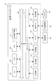
- each cell has a controller 35, 47, 49, 53, 55, 57, 61, 67, 69, 71, 75, 81 for controlling devices in the cell independently of the other cells.
- , 83, 85, 87 are provided respectively.
- those controllers are connected to a higher-level controller 89 and are controlled by the higher-level controller 89 in cooperation with each other.
- Each controller may be installed separately from the cell.
- the host controller 89 may be installed in any of the cells, or may be installed separately from the cells.
- any of the controllers 35, 47, 49, 53, 55, 57, 61, 67, 69, 71, 75, 81, 83, 85, 87 may have the function of the controller 89.
- each controller and the higher-level controller 89 may be configured by one or both of a programmable logic controller (PLC) and a robot controller (RC).
- PLC programmable logic controller
- RC robot controller
- the above-described cell combination of the production line 1 is an example, and the present invention is not limited to the above-described combination.
- the number, arrangement, and combination of the cells may be changed in accordance with the type and quantity of products to be produced, variations in work processes, and the like.
- cells to which work contents different from the above-described cells are assigned may be combined.
- FIG. 3 is an explanatory diagram illustrating an example of the internal configuration of the third assembly cell 21
- FIG. 4 is an explanatory diagram illustrating an example of the configuration of the positioning mechanism 94. 3 and 4, illustration of parts other than the base of the housing 21 ⁇ / b> A and illustration of the positioning member of the second pallet 59 are omitted as appropriate.
- the housing 21A of the third assembly cell 21 has a base 91.
- the above-mentioned first transport conveyor 21Ca and second transport conveyor 21Cb are installed in two stages by a gantry 93.
- a substrate mounting machine 97 is installed via a pedestal 95.
- the substrate mounting machine 97 is a dedicated working machine that includes an actuator that can move in the XYZ directions and performs a substrate mounting operation of mounting the above-described interface substrate (hereinafter, referred to as “interface substrate W4a”) on the first semi-finished product W3. is there.
- a vertical articulated robot 99 having six joints (six axes) is installed.
- the robot 99 grips and moves the component with the hand 101.
- a screw tightening machine 105 is installed via a stand 103.
- the screw tightening machine 105 is a dedicated working machine that includes an actuator that can move in the XYZ directions and performs a screw tightening operation for screwing the interface substrate W4a to the first semi-finished product W3.
- a cover fitting machine 109 is installed via a mount 107.
- the cover fitting machine 109 includes an actuator that can move in the XYZ directions, and is a dedicated working machine that performs a cover fitting operation for fitting the above-described interface cover (hereinafter, referred to as “interface cover W4b”) to the first semi-finished product W3. is there.
- the first transport conveyor 21Ca includes a pulley 100 provided at both ends in the transport direction (left-right direction) and a pair of narrow belts wound around the pulley 100 and provided at both ends in the width direction of the conveyor (front-rear direction). 102, and a pair of plate members 104 provided outside the pulley 100 and the belt 102 in the width direction.
- the pulley 100 is driven by a servomotor 92.
- the plate member 104 is positioned in the width direction by contacting both ends of the second pallet 59 being conveyed.
- the conveyor 21Cb has the same configuration.
- the first conveyor 21Ca stops the second pallet 59 at, for example, three work stations ST1, ST2, and ST3 by the position control by the controller 71 described above.
- the work station is a stop position where the second pallet 59 is stopped for a predetermined time.
- a predetermined assembly work process is assigned to each work station. The assigned work may be performed at each work station, or may be performed at another place. Further, the number of work stations is not particularly limited and may be other than three.
- the time until the next second semi-finished product W5 is supplied to the connection cell 23, that is, the supply interval time of the second semi-finished product W5, and the performance (movable range, payload, movable) of the robot 99 In this embodiment, three points are set in consideration of the speed and the like, thereby optimizing the improvement of the working efficiency of the robot and the shortening of the tact time.
- the first work station ST1 is located below the substrate placing machine 97, and is assigned a substrate placing operation process. This substrate mounting operation is performed at the first work station ST1. That is, the interface board W4a is placed on the first semi-finished product W3 by the board placement machine 97 on the second pallet 59 stopped at the work station ST1.
- the second work station ST2 and the third work station ST3 are respectively assigned both a screw tightening work step and a cover fitting work step.
- the screw tightening operation and the cover fitting operation are performed in another place different from the work stations ST2 and ST3. That is, the work (the first semi-finished product W3 on which the interface substrate W4a is mounted) mounted on the second pallet 59 stopped at the second work station ST2 is moved by the robot 99 to the screw tightening machine 105 to tighten the screws. Work is performed. During this time, the second pallet 59 from which the work has been taken out at the second work station ST2 is moved to the third work station ST3.
- the work (the first semi-finished product W3 in which the interface board W4a is screwed) is moved by the robot 99 to the cover fitting machine 109 to perform the cover fitting operation. Thereafter, the work (the first semi-finished product W3 fitted with the interface cover W4b) is moved by the robot 99 to the second pallet 59 stopped at the third work station ST3.
- One work may be assigned to one work station, such as a screw tightening work to the second work station ST2 and a cover fitting work to the third work station ST3.
- the work on which the screw tightening operation has been performed by the screw tightening machine 105 is returned to the second pallet 59 of the second work station ST2, and after the second pallet 59 is moved to the third work station ST3, the work is fitted with a cover.
- the tact time is extended.
- the work on which the screw tightening operation has been performed by the screw tightening machine 105 is transferred to the second work station ST2. It is possible to move to the cover fitting machine 109 without returning, and the tact time can be shortened.
- a push-up mechanism 111 that pushes up the second pallet 59 by a predetermined amount from the transfer surface of the first transfer conveyor 21Ca is provided inside the pair of belts 102.
- the push-up mechanism 111 is configured by, for example, a linear motion actuator that expands and contracts in the up-down direction and is disposed below the four corners of the second pallet 59.
- the second pallet 59 of the work station ST3 is sent out to the next connection cell 23 while leaving the second pallet 59 of the work stations ST1 and ST2, or the previous pallet 59 is left while the second pallet 59 of the work stations ST2 and ST3 is left. It is possible to receive the second pallet 59 from the connection cell 19 to the work station ST1 or the like.
- the first work station ST1 arranged at the most upstream side in the transport direction of the first transport conveyor 21Ca is provided with a positioning mechanism 94 for positioning the second pallet 59 at a predetermined position.
- the positioning mechanism 94 includes a pair of linear actuators 96 which are arranged at, for example, two places in the width direction of the conveyor (the front-back direction) and extend and contract in the up-down direction, and extend and contract in the transport direction (the left-right direction). And a pair of vertical actuators 106 for vertically moving the linear actuators 98.
- a pair of concave portions 108 (not shown in FIG. 3) into which the linear actuators 96 can be fitted are formed at positions corresponding to the pair of linear actuators 96.
- the second pallet 59 is transported from the connecting cell 19 to the work station ST1 and stopped.
- the linear actuator 96 extends, and the linear actuator 98 is raised by the lifting actuator 106.
- the concave portion 108 is fitted to the linear actuator 96, and the second pallet 59 is positioned at a predetermined position.
- the second work station ST2 and the third work station ST2 are controlled by the position control and the speed control by the servomotor 92 for driving the first conveyor 21Ca. Stopped at station ST3. Therefore, it is not necessary to install a sensor for detecting a pallet in each work station.
- the robot 99 may be a robot other than six axes (for example, five axes or seven axes), or may be a robot other than a vertical articulated robot such as a horizontal articulated robot.
- a robot having a plurality of joints it may be a dedicated work machine for transporting a work including an actuator movable in at least one of the XYZ ⁇ directions.
- at least one of the operations by the above-described dedicated working machine may be executed by the robot 99, and the corresponding dedicated working machine may be omitted.
- a dedicated working machine for performing other work may be installed.
- a sensor for detecting the second pallet 59 is provided at each of the work stations ST1, ST2, and ST3, and the first pallet 59 is provided based on the detection result of the sensor.
- the conveyor 21Ca may be controlled.
- FIG. 5 is an explanatory diagram illustrating an example of the internal configuration of the second component supply cell 17
- FIG. 6 is an explanatory diagram illustrating an example of the operation of the second component supply cell 17.
- illustration of parts other than the base of the housing 17A, the conveyors 17Ca, 17Cb, and the like is omitted as appropriate.
- the housing 17A of the second component supply cell 17 has a base 113.
- the above-mentioned carry-in conveyor 65L and carry-out conveyor 65R are installed corresponding to the receiving port 63 and the discharging port 64, respectively.
- a first conveyor 115 is provided at a substantially central portion of the base 113 in the front-rear direction.
- the first transport conveyor 115 is moved in the left-right direction by the slide mechanism 117, and is movable to a position corresponding to each of the carry-in conveyor 65L and the carry-out conveyor 65R.
- a second conveyor 119 is installed on the rear side of the base 113.
- the second conveyor 119 is moved in the left-right direction by the slide mechanism 120 and is movable to a position corresponding to each of the carry-in conveyor 65L and the carry-out conveyor 65R.
- first conveyor 17Ca and the second conveyor 17Cb are installed above and below the first conveyor 115, respectively.
- a first component container lifting / lowering mechanism 124 is provided on both left and right sides of a partition wall 122 that partitions the receiving port 63 and the discharge port 64.
- the first component container elevating mechanism 124 has, for example, a pair of guide rails 126, an elevating member 128 that moves up and down along the guide rails 126, and a pair of clamp members 130 attached to the elevating member 128, for example.
- the clamp member 130 can hold the component container 37 by engaging with an engaging portion (not shown) such as a flange portion of the component container 37, for example.
- the first component container lifting / lowering mechanism 124 provided on the receiving port 63 side can hold and raise / lower the component container 37 in which the component W4 received from the receiving port 63 is stored.
- the first component container lifting / lowering mechanism 124 provided on the discharge port 64 side can hold and raise and lower the empty component container 37 discharged from the discharge port 64.
- second component container lifting / lowering mechanisms 134 are provided at positions corresponding to the carry-in conveyor 65L and the carry-out conveyor 65R, respectively.
- the second component container elevating mechanism 134 has, for example, a pair of guide rails 136, an elevating member 138 that moves up and down along the guide rail 136, and a pair of clamp members 140 attached to the elevating member 138, for example.
- the clamp member 140 can hold the component container 37 by engaging with an engaging portion (not shown) such as a flange portion of the component container 37.
- the second component container lifting / lowering mechanism 134 provided on the left side can hold and move the component container 37 placed on the second transport conveyor 119 moved to the left side up and down.
- the second component container lifting / lowering mechanism 134 provided on the right side can hold the component container 37 placed on the second transport conveyor 119 moved to the right side and move it up and down.
- a robot base 123 is installed above the second transport conveyor 119 via a gantry 121.
- the robot base 123 is moved in the left-right direction by the slide mechanism 125, and forms an opening 142 exposing the component container 37 on the side opposite to the moving direction. That is, as shown in FIG. 5, when the robot base 123 moves to the right side, the opening 142 is formed on the left side, and when the robot base 123 moves to the left side, the opening 142 is formed on the right side.
- the component container 37 is lifted by the second component container elevating mechanism 134 to a height that does not make contact with the robot base 123.
- a vertical articulated robot 127 having, for example, six joints (six axes) is installed. It is only possible to move.
- the robot 127 grasps the component W4 stored in the component container 37 via the opening 142 by the hand 129, and moves to the second pallet 59 on the upper first conveyor 17Ca.
- the slide mechanism 144, the robot 127, and the like are integrally controlled by the controller 67 described above.
- the carry-in conveyor 65 ⁇ / b> L receives the two-tiered component container 37 containing the component W ⁇ b> 4 from the automatic guided vehicle 43 at the receiving port 63.
- the first component container lifting / lowering mechanism 124 holds and lifts the upper component container 37.
- the carry-in conveyor 65L, the first conveyor 115, and the second conveyor 119 convey the lower part container 37 to the rear left side.
- the second component container lifting / lowering mechanism 134 lifts the component container 37 and exposes the component container 37 from the left opening 142.
- the robot 127 starts the operation of moving (supplying) the component W4 stored in the component container 37 held in the left opening 142 to the second pallet 59 on the first transport conveyor 17Ca.
- the upper component container 37 held by the first component container lifting / lowering mechanism 124 is lowered onto the carry-in conveyor 65L.
- the carry-in conveyor 65L, the first transport conveyor 115, and the second transport conveyor 119 transport the second component container 37 to the left rear side, and the first transport conveyor 115 and The second transport conveyor 119 moves to the right to move the component container 37 to the right rear side (below the robot base 123).
- the second component container lifting / lowering mechanism 134 lifts and holds the component container 37 below the robot base 123.
- the first transport conveyor 115 and the second transport conveyor 119 move to the left before the component container 37 held in the left opening 142 becomes empty.
- the robot base 123 moves to the left as shown in the operation step (8), and the parts container 37 held on the right rear side is exposed from the opening 142 formed on the right side. Thereby, the robot 127 starts the operation of moving (supplying) the component W4 stored in the component container 37 held in the right opening 142 to the second pallet 59 on the first transport conveyor 17Ca.
- the second component container elevating mechanism 134 lowers the empty left component container 37 onto the second transport conveyor 119.
- the first transport conveyor 115 and the second transport conveyor 119 move rightward, and the first transport conveyor 115, the second transport conveyor 119, and the unloading conveyor 65R are empty components.
- the container 37 is moved to a position near the outlet 64.
- the first component container lifting / lowering mechanism 124 holds and lifts the empty component container 37.
- the carry-in conveyor 65L receives the two-tiered component container 37 containing the component W4 from the automatic guided vehicle 43 at the receiving port 63.
- the first component container lifting / lowering mechanism 124 of the receiving port 63 holds and lifts the upper component container 37.
- the loading conveyor 65L, the first transport conveyor 115, and the second transport conveyor 119 transport the lower part container 37 to the left rear side, and the second parts container lifting / lowering mechanism 134 lifts the parts container 37 to move the lower part of the robot base 123. Hold down.
- the first transport conveyor 115 and the second transport conveyor 119 move rightward until the component container 37 held in the right opening 142 becomes empty.
- the robot base 123 moves to the right as shown in the operation step (15), and the parts container 37 held on the left rear side is exposed from the opening 142 formed on the left side.
- the robot 127 starts the operation of moving (supplying) the component W4 stored in the component container 37 held in the left opening 142 to the second pallet 59 on the first transport conveyor 17Ca.
- the right component container 37 in which the second component container lifting / lowering mechanism 134 is empty is lowered onto the second transport conveyor 119, and the second transport conveyor 119 and the first transport conveyor 115 are moved.
- the carry-out conveyor 65R moves the empty component container 37 to the vicinity of the discharge port 64.
- an operation step (17) the empty component containers 37 held by the first component container lifting / lowering mechanism 124 are lowered to a two-tiered state, and the unloading conveyor 65R is unmannedly transported from the discharge port 64.
- the two-tiered empty parts container 37 is discharged to the car 43.
- the unmanned transport vehicle 43 is an unmanned transport vehicle 43 that has been emptied by supplying the component container 37 to the receiving port 63 in the operation step (12).
- the operation step (18) the first transport conveyor 115 and the second transport conveyor 119 move to the left.
- the upper parts container 37 held by the first parts container elevating mechanism 124 is lowered onto the carry-in conveyor 65L. Thereafter, the operation step (5) and subsequent steps are repeated.
- the robot 127 may be a robot other than six axes (for example, five axes or seven axes), or may be a robot other than a vertical articulated robot such as a horizontal articulated robot.
- the robot 127 may be a dedicated work machine for transporting a work including an actuator movable in at least one of the XYZ ⁇ directions.
- the production line 1 described above includes the assembling cells 9, 13, 21, 29 and the parts supply cells 5, 17, 25 (hereinafter, referred to as “assembly cells”) equipped with automatic working machines for performing predetermined operations on parts based on the specifications of the production line. Arrangement of “work cells 5, 9, 13, 17, 21, 25, 29” as appropriate) and connection cells 3, 7, 11, 15, 19, 23, 23 capable of repairing or discharging parts. 27, 31 are arranged adjacent to the working cells 5, 9, 13, 17, 21, 21, 25, 29 as necessary.
- “as needed” means that, for example, when the reliability and reliability of the work in each of the assembly cells and each of the component supply cells are high, a configuration in which the connection cells are not arranged can be adopted.
- the reliability and certainty of the work in the assembly cell or parts supply cell is low enough to realize completely unmanned operation, or if priority is given to improving the yield of the production line or continuing production, etc. It means that it is arranged adjacent to an assembly cell or a component supply cell.
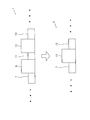
- all the work cells 5, 9, 13, 17, and Connected cells 3, 7, 11, 15, 19, 23, 27, 31 are arranged adjacent to 21, 25, 29 (the configuration shown in the first row of FIG. 7).
- the production line 1 configured as described above, based on the reliability of the work performed by the automatic working machine in each assembly cell and each component supply cell, the production line 1 is arranged adjacent to a specific assembly cell or a component supply cell.
- the linked cells may be deleted.
- the component supply cells 5, 17, and 25 are improved.
- the layout of the production line 1 can be optimized by deleting the connection cells 7, 19, and 27 adjacent on the downstream side (the configuration shown in the second row in FIG. 7).
- the assembly cell 9 can be further optimized by deleting the connection cells 11, 15, 23, 31 adjacent to the downstream side of 13, 21, 29.
- the connecting cells 15, 23, 31 of the connecting cells 11, 15, 23, 31 are provided with an elevating mechanism for the transport conveyor and constitute a pallet circulation structure. It is possible to adopt a configuration in which the connected cells 11 not provided are deleted (the configuration shown in the third row of FIG. 7).
- the production line 1 uses only one type of pallet without changing the type of pallet in the middle of the line, for example, the number of parts used is small, or the size of the pallet can be sufficiently secured.
- the production line 1 of the present embodiment it is easy to convert a plurality of cells into a single cell or a single cell into a plurality of cells.
- the first assembly cell 9 and the second assembly cell 13 can be replaced by a single assembly cell 12 due to the introduction of a new automatic working machine, technical improvement, technical innovation, and the like.
- the connection cell 11 disposed between the first assembly cell 9 and the second assembly cell 13 is deleted, and the first assembly cell 9 and the second assembly cell 13 are replaced with the assembly cell 12, thereby producing a production line. 1 can be optimized.
- the reliability and reliability of the substrate mounting operation assigned to the first work station ST1 and the cover fitting operation assigned to the third work station ST3 can be completely unmanned. If the degree of reliability is high, but the reliability and reliability of the screw tightening work assigned to the second work station ST2 are low to realize complete unmanned operation, for example, a plurality of cells may be formed as follows. Good. That is, as shown in FIG. 9, the third assembly cell 21 is divided into an assembly cell 20 having a first work station ST1 and a second work station ST2, and an assembly cell 22 having a third work station ST3.
- the connecting cell 23 arranged adjacent to the third assembling cell 21 is moved to the downstream side of the assembling cell 20 having the second work station ST2 having low reliability or the like (the new associating cell is replaced by a new one).
- the third component supply cell 25 is directly arranged without disposing the connection cell downstream of the assembly cell 22 having the third work station ST3 having high reliability or the like.
- the layout of the production line 1 can be optimized in this way.
- the production line 1 of the present embodiment is a production line for producing a product configured by combining a plurality of cells, and the plurality of cells is an automatic operation for performing a predetermined operation on a part.
- connection cells 3, 7, 11, 15, 19, 23, 27, and 31 are not used. Since the parts can be repaired or discharged, the production of products can be continued without stopping the production line 1. Further, by adopting such a configuration of the production line 1, the reliability of the work in the work cells 5, 9, 13, 17, 21, 25, 29 is improved by, for example, introduction of a new automatic working machine, technical improvement, technical innovation, or the like. If the certainty is improved, the connected cell adjacent to the corresponding work cell can be deleted. Further, for example, in order to improve the yield of the production line 1 and the like, the connection cells 3, 7, 11, 15, 19, 23, 27, and 31 were not arranged adjacent to each other at the beginning of the new production line.
- Connected cells can also be added. Further, for example, when changing the number, arrangement, type, combination, etc. of the work cells in accordance with the type and quantity of products to be produced, fluctuations in the production process, etc., the reliability of the work in the changed work cells, Connected cells can also be added, deleted, changed, etc. according to the nature and the like. In this way, the layout of the production line can be optimized, so that high flexibility (flexibility, adaptability, flexibility) can be realized.
- connection cells 3, 7, 11, 15, 19, 23, 27, and 31 are access units 3S, 7S, 11S, 15S, and 19S that enable the operator to repair or discharge parts. , 23S, 27S, 31S. Accordingly, when a predetermined operation is not properly performed on a part in the work cells 5, 9, 13, 17, 21, 25, and 29, the operator repairs the part or when the part cannot be repaired. Allows the operator to discharge the part from the production line 1. In this way, by performing the operation of the connection cell by the operator, it is possible to perform, for example, visual inspection work, maintenance work, work difficult with an automatic working machine, and the like, in addition to repair and discharge of parts.
- connection cells can be unmanned by manning the connection cells, automation of the production line 1 can be promoted. Furthermore, as compared with the case where the operation of the connection cell is performed by an automatic working machine, the cost can be reduced because an automatic working machine and a hand specially designed for grasping parts are not required.
- the work cells 5, 9, 13, 17, 21, 25, and 29 transfer the pallets 33, 59, and 73 on which the components are placed, to the downstream in the transport direction of the components on the production line 1.
- Conveyors 5Cb, 9Cb, 13Cb, 17Cb, 21Cb, 25Cb, and 29Cb Conveyors 5Cb, 9Cb, 13Cb, 17Cb, 21Cb, 25Cb, and 29Cb.
- the parts to be conveyed can be positioned, and the handling property and work accuracy by the automatic working machine can be improved. Further, the pallets 33, 59, 73 on which the components are placed are transported downstream by the first transport conveyor, and the pallets 33, 59, 73 from which the components are removed are transported upstream by the second transport conveyor. , The pallets 33, 59 and 73 can be circulated in the production line 1. As a result, the number of pallets can be significantly reduced as compared with a case where used pallets are transported from the exit to the entrance of the production line 1 by a cart or an unmanned transport vehicle, and pallet transport means such as an unmanned transport vehicle is unnecessary. Therefore, the cost can be reduced.
- connection cells 3, 15, 23, 31 include transport conveyors 3C, 15D, 23A, 31A capable of transporting the pallets 33, 59, 73 to both the upstream side and the downstream side; Lifting and lowering mechanisms 32, 46, 48, and 50 for moving the 3C, 15D, 23A, and 31A between a position corresponding to the first conveyor and a position corresponding to the second conveyor of the work cell.
- the circulation structure of the pallets 33, 59, 73 can be realized by the combination of the work cells 5, 9, 13, 17, 21, 25, 29 and the connection cells 3, 15, 23, 31 and the like. Also, by providing the lifting / lowering mechanisms 32, 46, 48, 50 of the conveyors 3C, 15D, 23A, 31A in the connecting cells, the transfer direction of the pallets 33, 59, 73 is not changed in the working cells, but only in the connecting cells. , The work cell can be standardized. Further, for example, the lifting mechanisms 32, 46, 48, and 50 carry one pallet when moving down the conveyors 3C, 15D, 23A, and 31A, and carry a different pallet when moving up.
- the third assembly cell 21 is a stop position for stopping the pallet 59 conveyed by the first conveyor 21Ca for a predetermined stop time, and each of the third assembly cells 21 is a predetermined stop position that is executed by the automatic working machine. It has a plurality of work stations ST1, ST2, ST3 to which work processes are assigned. As a result, the work can be assigned to each work station and designed, so that the production line 1 can be easily configured, and a single production line 1 can produce a large number of products.
- the third assembly cell 21 has a push-up mechanism 111 for pushing up the pallet 59 by a predetermined amount from the transfer surface of the first transfer conveyor 21Ca for each of the work stations ST1, ST2, ST3.
- the pallets 59 located at any of the work stations ST1, ST2, ST3 can be independently transported.
- the pallets 59 of each work station can be individually moved so as to fill the empty space. By doing so, it is possible to prevent the working stations ST1, ST2, and ST3 from being vacant, and it is possible to reduce the tact time.
- the third assembly cell 21 is disposed at the first work station ST1 located at the most upstream side in the transport direction, and includes a positioning mechanism 94 for positioning the pallet 59 at a predetermined position; And a servo motor 92 for driving the conveyor 21Ca.
- the position and speed of the pallet 59 can be accurately controlled by the servomotor 92, so that the accuracy of position control between the work stations can be improved and the moving speed of the pallet 59 can be reduced. Speed up and reduce travel time. Further, since it becomes unnecessary to install a position sensor at each work station, costs can be reduced.
- the third assembling cell 21 includes, as an automatic working machine, a board mounting machine 97, a screw tightening machine 105, and a cover fitting machine 109 specially designed for performing a predetermined work. And a multi-joint robot having a plurality of joints for moving parts between the pallet 59 and the screw tightening machine 105 or the cover fitting machine 109 or between the screw tightening machine 105 and the cover fitting machine 109 99.
- the work on the parts is executed by the dedicated work machine, and the movement of the parts is executed by the robot 99, and the different work is executed by exchanging the special work machine while leaving the articulated robot 99. It is possible to change to an assembly cell to be used, thereby increasing the flexibility of the assembly cell.
- it is possible to focus on the development of a dedicated working machine it is possible to flexibly respond to technical improvements, technological innovations, and the like.
- the production line 1 has the component supply cells 5, 17, and 25. And the outlets 40, 64, 78 for discharging empty component containers 37 to the automatic guided vehicle 43, and the receivers 39, 63, 77 are provided with It is arranged on the upstream side in the moving direction 42 of the automatic guided vehicle 43 than 64 and 78.
- the automatic guided vehicle 43 transports the component container 37 containing the component and supplies it to the receiving port of the component supply cell, and then moves to the discharge port, and removes the empty component container 37 from the discharge port of the component supply cell. You can receive. In this way, since the automatic guided vehicle 43 can supply and discharge the component containers 37 without changing the moving direction, the traveling distance of the automatic guided vehicle 43 can be reduced, and the supply and reception of the component containers 37 can be performed. Can be executed efficiently.
- the manufacturing method of the production line 1 according to the present embodiment is based on the specifications of the production line 1, and the work cells 5, 9, 13, 17, 21, 25 and 25 are provided with automatic working machines for performing predetermined operations on parts. 29, and the connecting cells 3, 7, 11, 15, 19, 23, 27, 31 capable of repairing or discharging parts are arranged adjacent to the working cells as required; Having.
- connection cell can be arranged adjacent to the work cell. In this way, the layout of the production line 1 can be optimized, so that high flexibility (flexibility, adaptability, flexibility) can be realized.
- the method further includes deleting the connected cells 3, 7, 11, 15, 19, 23, 27, 31 disposed adjacent to 17, 21, 25, 29.
- the layout of the production line 1 can be optimized.
- the production line 1 of the present embodiment is configured by combining a plurality of cells 3, 5, 7, 9, 11, 13, 15, 17, 19, 21, 23, 25, 27, 29, and 31.
- Each of the plurality of cells includes a transport conveyor 3C, 5C, 7A, 9C, which transports a pallet 33, 59, 73 on which at least one of the parts W1, W2, W3, W4, W5, W6 is placed.
- Reference numerals 25, 29, and 31 each include an automatic working machine that performs a predetermined work on the parts W1, W2, W3, W4, W5, and W6.
- the main work such as the supply of parts and the assembling of parts can be performed by the automatic work machine while the parts are conveyed in each cell constituting the production line 1, so that automation can be promoted.
- the production line 1 is configured by combining a plurality of cells, the number, arrangement, type, combination, and the like of each cell are changed to cope with variations in the type and quantity of products to be produced, work processes, and the like. This makes it possible to realize a highly flexible production line.
- the cells 7, 11, 15, 19, 23, 27, etc. which can be manually operated by the operator, are arranged between the cells 5, 9, 13, 17, 21, 25, 29 provided with the automatic working machines. , Check whether the work has been properly performed by the automatic work machine, and if the work is not performed properly or if the work cannot be performed due to failure of the automatic work machine, etc. Then, it is possible to supplement difficult tasks manually.
- the screw tightening machine 105 and the cover fitting machine 109 are installed on both the gantry 103 and the gantry 107. Can be simultaneously executed in two systems in parallel.
- This modification is an example in which the time required for the screw fastening operation process and the cover fitting operation process (for example, 60 seconds) is longer than the tact time (for example, 45 seconds) set in the third assembly cell 21X.
- the second work station ST2 and the third work station ST3 are assigned the same work process, that is, both the screw tightening work process and the cover fitting work process in this example.
- the third assembly cell 21X operates as follows. That is, the work (the first semi-finished product W3 on which the interface substrate W4a is mounted) mounted on the second pallet 59 stopped at the second work station ST2 is moved by the robot 99 to one of the screw tighteners (for example, the gantry 103). 105 and the other (for example, the gantry 107) are alternately moved to the screw tightener 105. In each of the pedestals 103 and 107, a screw fastening operation is performed by the screw fastening machine 105, and a cover fitting operation is performed by the cover fitting machine 109.
- the screw tighteners for example, the gantry 103
- 105 and the other for example, the gantry 107
- the second pallet 59 from which the work has been taken out at the second work station ST2 is moved to the third work station ST3, and is covered by the robot 99 with one of the cover fitting machine 109 (for example, the gantry 103) and the other (for example, the gantry 107) of the cover.
- the work is placed alternately from the fitting machine 109.
- work processes that require a longer time than the tact time of the third assembly cell 21X can be executed simultaneously and in parallel by two systems.
- the above work process can be executed without extending the tact time of the third assembly cell 21X.
- two or more work stations to which the same work process is assigned as described above need not necessarily be provided in the same cell.
- the joint unit 109 may be installed in a cell different from the third assembly cell 21X (for example, another assembly cell).
- a second work station ST2 to which work by one of the screw tightening machines 105 and the cover fitting machine 109 is allocated is provided in the third assembly cell 21X, and the other screw tightening machine 105 and the cover are provided in another assembly cell.
- a third work station ST3 to which work by the fitting machine 109 is assigned may be provided.
- the structure in which the pallets are circulated in the production line 1 is not necessarily required.
- a pallet is supplied by an automatic working machine or an operator at the most upstream connection cell (the connection cell 3 in the above embodiment) of the production line, and the most downstream connection cell (the connection cell 31 in the above embodiment) of the production line.
- the pallets may be collected by an automatic working machine or an operator, and the pallets may be conveyed from the exit of the production line to the entrance by, for example, a bogie or an automatic guided vehicle.
- the pallet is replaced by the automatic working machine or the operator at that location (the connection cells 15, 23 in the above embodiment). Connected cells may be arranged.
- Example of controller hardware configuration> an example of the hardware configuration of the above-described upper controller 89 will be described with reference to FIG.
- the controllers 35, 47, 49, 53, 55, 57, 61, 67, 69, 71, 75, 81, 83, 85, and 87 of each cell may have the same hardware configuration.
- FIG. 11 the configuration relating to the function of supplying the driving power to the servo motor and the like is omitted as appropriate.
- the host controller 89 includes, for example, a CPU 901, a ROM 903, a RAM 905, a dedicated integrated circuit 907 constructed for a specific use such as an ASIC or an FPGA, an input device 913, and an output device 915. , A recording device 917, a drive 919, a connection port 921, and a communication device 923. These components are connected so that signals can be transmitted to each other via a bus 909 and an input / output interface 911.
- the program can be recorded in, for example, the ROM 903, the RAM 905, the recording device 917, or the like.
- the program is temporarily or non-temporarily (permanently) recorded on a magnetic disk such as a flexible disk, an optical disk such as various CD / MO disks / DVDs, or a removable recording medium 925 such as a semiconductor memory. You can keep it.
- a recording medium 925 can be provided as so-called package software.
- the programs recorded on these recording media 925 may be read by the drive 919 and recorded on the recording device 917 via the input / output interface 911, the bus 909, and the like.
- the program can also be recorded on, for example, a download site, another computer, another recording device, or the like (not shown).
- the program is transferred via a network NW such as a LAN or the Internet, and the communication device 923 receives the program.
- NW such as a LAN or the Internet
- the program received by the communication device 923 may be recorded in the recording device 917 via the input / output interface 911, the bus 909, and the like.
- the program can also be recorded on, for example, an appropriate externally connected device 927.
- the program may be transferred through an appropriate connection port 921 and recorded in the recording device 917 via the input / output interface 911, the bus 909, or the like.
- ⁇ Operation of the production line 1 is realized by the CPU 901 executing various processes according to the program recorded in the recording device 917.
- the CPU 901 may, for example, directly read out the program from the recording device 917 and execute the program, or may execute the program after temporarily loading it into the RAM 905. Further, for example, when the CPU 901 receives a program via the communication device 923, the drive 919, and the connection port 921, the CPU 901 may directly execute the received program without recording it on the recording device 917.
- the CPU 901 may perform various processes as needed based on signals and information input from an input device 913 such as a mouse, a keyboard, and a microphone (not shown).
- an input device 913 such as a mouse, a keyboard, and a microphone (not shown).
- the CPU 901 may output the result of executing the above processing from an output device 915 such as a display device or an audio output device.
- the data may be transmitted via the port 921 or may be recorded on the recording device 917 or the recording medium 925.
Landscapes
- Engineering & Computer Science (AREA)
- Mechanical Engineering (AREA)
- Robotics (AREA)
- Physics & Mathematics (AREA)
- Manufacturing & Machinery (AREA)
- Quality & Reliability (AREA)
- General Engineering & Computer Science (AREA)
- General Physics & Mathematics (AREA)
- Automation & Control Theory (AREA)
- Automatic Assembly (AREA)
- General Factory Administration (AREA)
- Intermediate Stations On Conveyors (AREA)
- Multi-Process Working Machines And Systems (AREA)
Abstract
Priority Applications (4)
| Application Number | Priority Date | Filing Date | Title |
|---|---|---|---|
| JP2020528675A JP7276718B2 (ja) | 2018-07-04 | 2018-10-03 | 生産ライン及び生産ラインの製造方法 |
| CN201880095286.2A CN112400145A (zh) | 2018-07-04 | 2018-10-03 | 生产线及生产线的制造方法 |
| EP18925579.7A EP3819731A4 (fr) | 2018-07-04 | 2018-10-03 | Ligne de production et procédé de fabrication de ligne de production |
| US17/128,208 US20210107102A1 (en) | 2018-07-04 | 2020-12-21 | Production line and method of manufacturing production line |
Applications Claiming Priority (2)
| Application Number | Priority Date | Filing Date | Title |
|---|---|---|---|
| JP2018127852 | 2018-07-04 | ||
| JP2018-127852 | 2018-07-04 |
Related Child Applications (1)
| Application Number | Title | Priority Date | Filing Date |
|---|---|---|---|
| US17/128,208 Continuation US20210107102A1 (en) | 2018-07-04 | 2020-12-21 | Production line and method of manufacturing production line |
Publications (1)
| Publication Number | Publication Date |
|---|---|
| WO2020008659A1 true WO2020008659A1 (fr) | 2020-01-09 |
Family
ID=69060043
Family Applications (1)
| Application Number | Title | Priority Date | Filing Date |
|---|---|---|---|
| PCT/JP2018/037037 WO2020008659A1 (fr) | 2018-07-04 | 2018-10-03 | Ligne de production et procédé de fabrication de ligne de production |
Country Status (5)
| Country | Link |
|---|---|
| US (1) | US20210107102A1 (fr) |
| EP (1) | EP3819731A4 (fr) |
| JP (1) | JP7276718B2 (fr) |
| CN (1) | CN112400145A (fr) |
| WO (1) | WO2020008659A1 (fr) |
Families Citing this family (3)
| Publication number | Priority date | Publication date | Assignee | Title |
|---|---|---|---|---|
| JP2022101474A (ja) * | 2020-11-18 | 2022-07-06 | ザ・ボーイング・カンパニー | 対応付け装置及び対応付け方法 |
| WO2023041184A1 (fr) * | 2021-09-20 | 2023-03-23 | Abb Schweiz Ag | Unité de base pour système d'alimentation, système d'alimentation, système industriel, et procédé de manipulation d'un système d'alimentation |
| WO2024079770A1 (fr) * | 2022-10-11 | 2024-04-18 | Dynamic Technologies S.P.A. | Appareil automatisé pour raccordement structural d'éléments métalliques et procédé associé |
Citations (8)
| Publication number | Priority date | Publication date | Assignee | Title |
|---|---|---|---|---|
| JPH0557570A (ja) * | 1991-08-31 | 1993-03-09 | Mazda Motor Corp | ワークの検査加工方法及び検査加工装置 |
| JPH071298A (ja) * | 1993-06-11 | 1995-01-06 | Sanken Electric Co Ltd | ユニット型物品生産装置とそれを使用した物品生産ラインシステム |
| JP2004001990A (ja) * | 2002-04-17 | 2004-01-08 | Shinmei Ind Co Ltd | ワーク搬送装置およびトランスファ装置 |
| JP2008213129A (ja) * | 2007-03-07 | 2008-09-18 | Seiko Epson Corp | 生産システム用汎用セル及び該汎用セルを用いた生産システム |
| JP2009199488A (ja) * | 2008-02-25 | 2009-09-03 | Jtekt Corp | シーケンス制御システム |
| JP2013158876A (ja) * | 2012-02-03 | 2013-08-19 | Canon Inc | 組立装置および組立方法 |
| JP2016203348A (ja) | 2015-04-28 | 2016-12-08 | セイコーエプソン株式会社 | ロボットシステム |
| WO2018051476A1 (fr) * | 2016-09-16 | 2018-03-22 | 富士機械製造株式会社 | Machine automatisée de transfert de pièces |
Family Cites Families (11)
| Publication number | Priority date | Publication date | Assignee | Title |
|---|---|---|---|---|
| JPH04261763A (ja) * | 1991-02-15 | 1992-09-17 | Sony Corp | 組立・加工装置 |
| JP2865507B2 (ja) * | 1992-11-30 | 1999-03-08 | 株式会社ピーエフユー | 混流生産システムおよびその運転方法 |
| JPH06168249A (ja) * | 1992-11-30 | 1994-06-14 | Pfu Ltd | 混流生産システムおよびその運転方法 |
| JP2001121386A (ja) | 1999-10-19 | 2001-05-08 | Toyoda Mach Works Ltd | 生産ライン |
| JP4789103B2 (ja) | 2004-08-06 | 2011-10-12 | セイコーインスツル株式会社 | 生産ライン |
| JP2009151753A (ja) * | 2007-11-27 | 2009-07-09 | Asmo Co Ltd | モータ製品の生産システム及び生産方法 |
| JP5289226B2 (ja) | 2008-11-20 | 2013-09-11 | パナソニック株式会社 | フレキシブル生産システム |
| JP2011152615A (ja) * | 2010-01-28 | 2011-08-11 | Honda Motor Co Ltd | ワーク組立て方法 |
| JP2011175498A (ja) | 2010-02-25 | 2011-09-08 | Nsk Ltd | 生産数制御システム |
| JP6174359B2 (ja) * | 2013-04-12 | 2017-08-02 | Ntn株式会社 | 生産設備 |
| DE202017101643U1 (de) * | 2017-03-21 | 2018-05-08 | Kuka Systems Gmbh | Fertigungsstation |
-
2018
- 2018-10-03 CN CN201880095286.2A patent/CN112400145A/zh active Pending
- 2018-10-03 JP JP2020528675A patent/JP7276718B2/ja active Active
- 2018-10-03 WO PCT/JP2018/037037 patent/WO2020008659A1/fr active Application Filing
- 2018-10-03 EP EP18925579.7A patent/EP3819731A4/fr not_active Withdrawn
-
2020
- 2020-12-21 US US17/128,208 patent/US20210107102A1/en not_active Abandoned
Patent Citations (8)
| Publication number | Priority date | Publication date | Assignee | Title |
|---|---|---|---|---|
| JPH0557570A (ja) * | 1991-08-31 | 1993-03-09 | Mazda Motor Corp | ワークの検査加工方法及び検査加工装置 |
| JPH071298A (ja) * | 1993-06-11 | 1995-01-06 | Sanken Electric Co Ltd | ユニット型物品生産装置とそれを使用した物品生産ラインシステム |
| JP2004001990A (ja) * | 2002-04-17 | 2004-01-08 | Shinmei Ind Co Ltd | ワーク搬送装置およびトランスファ装置 |
| JP2008213129A (ja) * | 2007-03-07 | 2008-09-18 | Seiko Epson Corp | 生産システム用汎用セル及び該汎用セルを用いた生産システム |
| JP2009199488A (ja) * | 2008-02-25 | 2009-09-03 | Jtekt Corp | シーケンス制御システム |
| JP2013158876A (ja) * | 2012-02-03 | 2013-08-19 | Canon Inc | 組立装置および組立方法 |
| JP2016203348A (ja) | 2015-04-28 | 2016-12-08 | セイコーエプソン株式会社 | ロボットシステム |
| WO2018051476A1 (fr) * | 2016-09-16 | 2018-03-22 | 富士機械製造株式会社 | Machine automatisée de transfert de pièces |
Non-Patent Citations (1)
| Title |
|---|
| See also references of EP3819731A4 |
Also Published As
| Publication number | Publication date |
|---|---|
| EP3819731A1 (fr) | 2021-05-12 |
| US20210107102A1 (en) | 2021-04-15 |
| JPWO2020008659A1 (ja) | 2021-05-20 |
| EP3819731A4 (fr) | 2022-03-23 |
| CN112400145A (zh) | 2021-02-23 |
| JP7276718B2 (ja) | 2023-05-18 |
Similar Documents
| Publication | Publication Date | Title |
|---|---|---|
| US20210107102A1 (en) | Production line and method of manufacturing production line | |
| KR101716524B1 (ko) | 기판 컨테이너 보관 시스템 | |
| US6308496B1 (en) | Computer manufacturing system | |
| EP0277423B1 (fr) | Monture programmable et cellule d'assemblage | |
| US5321885A (en) | Method and apparatus for manufacturing printed wiring boards | |
| KR101927363B1 (ko) | 기판 컨테이너 보관 시스템과 연결하기 위한 일체형 시스템 | |
| US9919871B2 (en) | Buffer station for stocker system | |
| JP3068546B2 (ja) | ロボットの制御方法及びその装置 | |
| JPH10223728A (ja) | 半導体ウェハキャリアの格納及び装填用コンパクト装置及び方法 | |
| CN112041112A (zh) | 汽车白车身组件的组焊或拼接生产线 | |
| US9218994B2 (en) | Two-dimensional transfer station used as interface between a process tool and a transport system and a method of operating the same | |
| KR100684157B1 (ko) | 반송시스템 | |
| WO2021106026A1 (fr) | Système d'entrepôt | |
| US20020064440A1 (en) | Production line constructing system | |
| US20080041694A1 (en) | Buffer station for stocker system | |
| Kaempf | Automated wafer transport in the wafer Fab | |
| WO2021145087A1 (fr) | Dispositif de transfert de foup | |
| CN111736073B (zh) | 一种伺服电机的检测流水线 | |
| KR100245650B1 (ko) | 반도체 제조라인의 계측시스템 | |
| US10627809B2 (en) | Multilevel fabricators | |
| KR101491858B1 (ko) | 모듈화된 팰릿 반송 및 저장 시스템 | |
| CN220884615U (zh) | 整车制造岛区 | |
| KR20080019085A (ko) | 타워형 대차 보관 및 이송설비 | |
| EP2062287B1 (fr) | Station tampon pour un système de stockage | |
| JPH1149349A (ja) | 生産設備のセルシステム |
Legal Events
| Date | Code | Title | Description |
|---|---|---|---|
| 121 | Ep: the epo has been informed by wipo that ep was designated in this application |
Ref document number: 18925579 Country of ref document: EP Kind code of ref document: A1 |
|
| ENP | Entry into the national phase |
Ref document number: 2020528675 Country of ref document: JP Kind code of ref document: A |
|
| NENP | Non-entry into the national phase |
Ref country code: DE |
|
| WWE | Wipo information: entry into national phase |
Ref document number: 2018925579 Country of ref document: EP |
|
| ENP | Entry into the national phase |
Ref document number: 2018925579 Country of ref document: EP Effective date: 20210204 |