WO2020008603A1 - 昇降機監視装置 - Google Patents
昇降機監視装置 Download PDFInfo
- Publication number
- WO2020008603A1 WO2020008603A1 PCT/JP2018/025572 JP2018025572W WO2020008603A1 WO 2020008603 A1 WO2020008603 A1 WO 2020008603A1 JP 2018025572 W JP2018025572 W JP 2018025572W WO 2020008603 A1 WO2020008603 A1 WO 2020008603A1
- Authority
- WO
- WIPO (PCT)
- Prior art keywords
- control panel
- signal
- elevator
- display
- unit
- Prior art date
- Legal status (The legal status is an assumption and is not a legal conclusion. Google has not performed a legal analysis and makes no representation as to the accuracy of the status listed.)
- Ceased
Links
Images


Classifications
-
- B—PERFORMING OPERATIONS; TRANSPORTING
- B66—HOISTING; LIFTING; HAULING
- B66B—ELEVATORS; ESCALATORS OR MOVING WALKWAYS
- B66B3/00—Applications of devices for indicating or signalling operating conditions of elevators
-
- B—PERFORMING OPERATIONS; TRANSPORTING
- B66—HOISTING; LIFTING; HAULING
- B66B—ELEVATORS; ESCALATORS OR MOVING WALKWAYS
- B66B5/00—Applications of checking, fault-correcting, or safety devices in elevators
-
- B—PERFORMING OPERATIONS; TRANSPORTING
- B66—HOISTING; LIFTING; HAULING
- B66B—ELEVATORS; ESCALATORS OR MOVING WALKWAYS
- B66B7/00—Other common features of elevators
Definitions
- the present invention relates to an elevator monitoring device that is applied to renewal of an elevator such as an elevator or an escalator and that is connected to a control panel that controls the operation of the elevator.
- a control panel that controls the operation of the elevator is installed in the machine room of the building where the elevator is installed.
- the elevator substantially indicates an elevator car and an escalator.
- the escalator usually has a service direction as a service for passengers, but since the service direction can be reversed, it can be regarded as an elevator.
- an elevator monitoring device connected to the control panel will be installed.
- the elevator monitoring device may be referred to as a monitoring device.
- the control panel and the monitoring device can be replaced at the time of renewal.
- the monitoring device is also called a monitoring panel or a monitoring circuit.
- the communication connection between the control panel and the monitoring panel is generally performed in a wired manner using electric wires.
- both the control panel and the monitoring panel are provided with a wireless communication function, it is also possible to apply a wireless method as a communication connection.
- an elevator that sends operation signals of both the existing control panel and the new control panel to the new monitoring panel through the signal switching unit of the interface device, and monitors the new control panel when the existing control panel is removed.
- Patent Document 1 In the technology according to Patent Document 1 described above, it is necessary to provide an existing monitoring panel circuit and a new monitoring panel circuit in a new control panel installed in a machine room. In addition, the technology according to Patent Document 1 proposes connecting a new monitoring panel to an existing monitoring panel and installing both the existing monitoring panel and the new monitoring panel for a monitoring panel installed in a monitoring room. . However, there are restrictions on the installation location, and for example, if the installation space is narrow, the technique according to Patent Literature 1 may not be applicable.
- Patent Literature 2 needs to simultaneously monitor the existing monitoring panel and the new monitoring panel by sending the operation signals of both the existing and the new control panel to the new monitoring panel.
- there is a restriction on the installation location For example, if the installation space is narrow, the technique according to Patent Document 2 may not be applicable.
- the present invention has been made in order to solve such a problem, and an object of the present invention is to provide an elevator monitoring device capable of easily renewing a control panel without restriction on an installation space at the time of renewal.
- the elevator monitoring device of the present invention has a communication connection receiving unit that receives, as an input, the presence or absence of a connection related to communication transmission and reception with one or more control panels that control the operation of the elevator, A signal input / output unit that outputs a connection state signal that specifies a connected control panel among one or more control panels; and a connection state based on the connection state signal output from the signal input / output unit.
- a signal allocating unit for allocating unique information to the control panel being configured, and a signal processing unit for performing identification processing of the control panel to which the unique information is allocated.
- FIG. 3 is a schematic diagram illustrating an arrangement relationship of a control panel in a state where a part of an existing control panel of the elevator monitoring device illustrated in FIG. 2 is disconnected.
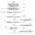
- 4 is a flowchart showing an operation process of the elevator monitoring device applied to the states of FIGS. 2 and 3.
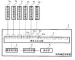
- FIG. 1 is a schematic diagram showing a basic configuration of an elevator monitoring device 2 according to Embodiment 1 of the present invention as being connected to one or more control panels 1a to 1d.
- the elevator monitoring device 2 includes a signal input / output unit 3, a signal allocation unit 4, a signal processing unit 5, and a display unit 6.
- the signal input / output unit 3 has a plurality of connection points where the connection of the new control panel with respect to the control panels 1a to 1d can be attached and the connection of the existing control panel can be removed.
- the signal input / output unit 3 has eleven connection points. These connection points correspond to the case where the control panels 1a to 1d and the elevator monitoring device 2 are connected by communication in a wired manner.
- the connection point in FIG. 1 illustrates a case where the connector is generally attached and detached with a connector attached to the end of the electric wire.
- the signal input / output unit 3 itself has a function of transmitting and receiving signals to and from the connected control panels 1a to 1d, and also outputs a transmission output of a connection state signal for a system of the connected control panels 1a to 1d. This is performed for the allocation unit 4.
- the connection state signal specifies the control panels 1a to 1d in the connected state. This connection state signal is hereinafter referred to as a signal.
- FIG. 1 shows a configuration in which the control panels 1a to 1d and the elevator monitoring device 2 are connected to each other in a wired manner, but may be changed to a wireless manner.
- the plurality of connection points serve as a communication connection receiving unit that receives the presence / absence of a connection related to communication transmission / reception with the control panels 1a to 1d having a wireless communication function.
- This communication connection receiving unit also has a specification having a wireless communication function.
- the signal input / output unit 3 has a function of transmitting a signal for the system of the connected control panels 1a to 1d to the signal allocating unit 4, similarly to the case of the wired system.
- the signal allocating unit 4 allocates unique information to each of the systems of the control panels 1a to 1d that have received the signal transmitted from the signal input / output unit 3.
- An example of the unique information is an Internet protocol address IP.
- the signal allocating unit 4 allocates the IP to the receiving system of the signal transmitted from the signal input / output unit 3. Note that it is preferable to use the Internet protocol address IP for the wireless communication function of the communication connection receiving unit in order to identify the control panels 1a to 1d.
- control panel 1a to 1d Specific information to be assigned to the control panels 1a to 1d includes, for example, a control panel (1) for the control panel 1a, a control panel (2) for the control panel 1b, a control panel (3) for the control panel 1c, and a control panel.
- the control panel (4) can be exemplified as the control panel 1d.
- the signal processing unit 5 performs the identification processing of the signal to which the unique information is allocated, and performs the display processing for displaying the state of the signal according to the identification processing. Further, the signal processing unit 5 transmits a display signal indicating a result of the display processing to the display unit 6.
- the display unit 6 displays the display signal received from the signal processing unit 5 on a display screen.
- the signal input / output unit 3 sends a signal to the signal allocating unit 4 to transmit a signal for a new control panel corresponding to the newly added elevator. Therefore, the signal allocating unit 4 additionally allocates unique information to the newly added control panel system.
- the signal processing unit 5 additionally displays a new elevator corresponding to the additional allocation of the unique information on the display screen of the display unit 6 as a display process.
- the signal input / output unit 3 interrupts the signal allocating unit 4 with respect to the transmission output of the signal of the existing control panel system corresponding to the removed existing elevator. . Therefore, the signal allocating unit 4 deletes the allocation of the unique information to the system of the removed existing control panel. As a display process, the signal processing unit 5 deletes the display of the existing elevator corresponding to the deletion of the assignment of the unique information on the display screen of the display unit 6.
- the signal processing unit 5 optimizes the display layout as a display process when adding a display when such a new elevator is added and when changing a display screen due to display deletion when an existing elevator is removed. Relocate the connected control panel.
- FIG. 2 is a schematic diagram showing an arrangement relationship with the existing control panels 7a to 7d when the new control panels 8a and 8b are connected to the elevator monitoring device 2 described above.
- the signal input / output unit 3 transmits and outputs a new signal indicating the connection between the new control panels 8a and 8b to the signal allocation unit 4.
- the signal allocating unit 4 allocates new unique information to each of the new control panels 8a and 8b. Further, the signal allocating unit 4 transmits the signal to which the new unique information is allocated to the signal processing unit 5.
- the signal processing unit 5 performs a process of identifying a signal to which new unique information is assigned. Further, the signal processing unit 5 transmits a display signal indicating a result of the display processing for displaying the state of the signal to the display unit 6 according to the identification processing.
- the unique information assigned to the existing control panels 7a to 7d includes, for example, the existing control panel (1) for the existing control panel 7a, the existing control panel (2) for the existing control panel 7b, and the existing control panel 7c for the existing control panel 7c.
- the existing control panel (4) can be exemplified as the existing control panel (3) and the existing control panel 7d.
- the unique information assigned to the new control panels 8a and 8b can be exemplified, for example, in the case where the new control panel 8a is a new control panel (5) and the new control panel 8b is a new control panel (6). .
- FIG. 3 is a schematic diagram showing the arrangement of the control panels of the elevator monitoring device 2 shown in FIG. 2 with some of the existing control panels 7a to 7d disconnected.
- the removal is performed without turning off the power of the other existing control panels 7 a and 7 b and the new control panels 8 a and 8 b and the elevator monitoring device 2. Work is performed. That is, the connector 11c connected to the control panel 7c and the connector 11d connected to the control panel 7d are removed from the connection points of the signal input / output unit 3.
- the signal processing unit 5 transmits to the display unit 6 that the signal relating to the deleted unique information is not displayed. Therefore, the display unit 6 can hide the operation state of the elevator corresponding to the signal related to the deleted unique information.
- FIG. 4 is a flowchart showing an operation process of the elevator monitoring device 2 applied to the states of FIGS. 2 and 3.
- step S41 the signal allocating unit 4 confirms a signal transmitted and output from the signal input / output unit 3, and allocates unique information to a signal receiving system.
- step S42 the signal processing unit 5 checks at a certain interval whether or not the unique information has been allocated by the signal allocating unit 4. Specifically, the signal processing unit 5 executes such assignment confirmation of the unique information by the following processes from step S43 to step S49.
- step S43 the signal processing unit 5 determines whether there is a change in unique information allocation. If the result of this determination is that there is no change in unique information allocation, the signal processing unit 5 returns to the process of step S42. On the other hand, when there is a change in the unique information allocation, the process proceeds to step S44, and the signal processing unit 5 determines whether there is an additional unique information allocation. If the result of this determination is that there is an addition of unique information, the process proceeds to step S45, where the signal processing unit 5 displays a new elevator on the display unit 6. Thereafter, the signal processing unit 5 proceeds to the process of step S46, as in the case where the unique information is not added.
- step S46 the signal processing unit 5 determines whether there is a deletion of the unique information allocation. If the result of this determination is that there is a deletion of the unique information allocation, the process proceeds to step S47, where the signal processing unit 5 deletes the corresponding existing elevator on the display unit 6, that is, hides it. After that, the signal processing unit 5 proceeds to the process of step S48 as in the case where the unique information is not deleted.
- step S48 the signal processing unit 5 determines whether or not the elevators are arranged as set based on the increase and decrease of the elevators due to the increase and decrease of the control panel. In simple terms, this determination is a determination as to whether the display layout of the display unit 6 is appropriate.
- step S49 the signal processing unit 5 confirms the setting of the display unit 6 and rearranges the elevator that should exist at present.
- the signal processing unit 5 returns to the process of step S42 and repeats the subsequent processes.
- the signal allocating unit automatically allocates the unique information to the system of the control panel that has received the signal transmitted from the signal input / output unit. Further, the signal processing unit 5 performs a process of identifying a signal to which unique information is assigned. Then, the signal processing unit performs a display process in accordance with the identification process, and displays a state of the signal including the change on a display screen of the display unit. Thereby, the signal processing unit can appropriately display the monitoring information of the currently used control panel. That is, according to the elevator monitoring device, even when renewal work is involved, only necessary monitoring information can be appropriately displayed on the display unit.
- the control panel can be easily renewed without turning off the power of the elevator that is continuously used. Further, there is no need to newly install an elevator monitoring device, and the control panel currently used can be monitored using only the existing elevator monitoring device. Therefore, the manufacturing cost and the number of days required for newly installing the elevator monitoring device are not required. Furthermore, work such as stopping the elevator and shutting off the power supply of the elevator monitoring device, which is normally required when changing the connection from the existing control panel to the new control panel, becomes unnecessary, and the renewal can be easily performed. .
Landscapes
- Indicating And Signalling Devices For Elevators (AREA)
Abstract
リニューアル時に設置スペースの制約がなく、制御盤を容易にリニューアルできる昇降機監視装置を提供する。昇降機監視装置において、信号入出力部は、制御盤との間で通信送受に係る接続の有無を通信接続受付部で受け付け、接続の有る制御盤の系統についての接続状態信号の送信出力を行う。信号割付部は、信号入出力部から送信される接続状態信号を受信した制御盤の系統に固有情報を割り付ける。信号処理部は、固有情報の割り付けられた信号の識別処理に応じて信号の状態を表示させるための表示処理を行う。
Description
本発明は、エレベータ、エスカレータ等の昇降機のリニューアルに適用され、昇降機の動作を制御する制御盤と通信接続される昇降機監視装置に関する。
従来、昇降機が据付けられる建物の機械室には、昇降機の動作を制御する制御盤が設置される。ここで、昇降機とは、実質上、エレベータの乗りかご、並びにエスカレータを示すものである。エスカレータは、通常、乗客向けのサービスとして、運行方向が定められるが、その運行方向を反転させることができるため、昇降機とみなせる。
また、建物の監視室には、制御盤と通信接続される昇降機監視装置が設置される。尚、以下の説明では、昇降機監視装置のことを監視装置と呼ぶこともある。制御盤及び監視装置は、リニューアルに際して、何れも交換可能なものである。尚、監視装置については、監視盤、監視回路とも呼ばれる。
因みに、制御盤と監視盤との通信接続は、汎用的に電線を用いて有線方式で行われる。ただし、制御盤と監視盤との双方に無線通信機能を持たせれば、通信接続として無線方式を適用することも可能である。
昇降機が併設されたエレベータであって、且つリニューアルを行う場合に用いられる、監視装置に係る周知技術は、少なくない。一例として、既設監視盤用回路及び新設監視盤用回路を新制御盤に設け、リニューアル前後でエレベータを全て監視するエレベータのリニューアル方法が挙げられる(例えば、特許文献1参照)。
他例として、既設の制御盤及び新設の制御盤の両方の動作信号を、インターフェース装置の信号切り替え部を通して新設の監視盤に送り、既設の制御盤の撤去時に新設の監視盤で監視を行うエレベータのリニューアルシステムが挙げられる(例えば、特許文献2参照)。
上述した特許文献1に係る技術は、機械室に設置される新制御盤に、既設監視盤用回路及び新設監視盤用回路を設ける必要がある。また、特許文献1に係る技術は、監視室に設置される監視盤についても、既設監視盤に新監視盤を接続して、既設監視盤及び新監視盤の双方を設置する提案がされている。ところが、設置場所に制約があり、例えば、設置スペースが狭い場合には、特許文献1に係る技術は、適用できなくなるおそれがある。
また、特許文献2に係る技術は、既設・新設の制御盤の両方の動作信号を新設の監視盤に送ることにより、既設の監視盤及び新設の監視盤で同時に監視を行う必要がある。こうした場合も、同様に、設置場所に制約があり、例えば、設置スペースが狭い場合には、特許文献2に係る技術は、適用できなくなるおそれがある。
更に、新設の監視盤を設置するスペースがなく、既設の監視盤を改造して対処する場合には、リニューアルを行う際に、既設の監視盤に繋がれている既設の昇降機の電源を、遮断しなければならない。こうした場合には、手間が掛かり過ぎてしまう。
本発明は、このような問題点を解決するためになされたものであり、リニューアル時に設置スペースの制約がなく、制御盤を容易にリニューアルできる昇降機監視装置を提供することを目的とする。
上記目的を達成するため、本発明の昇降機監視装置は、昇降機の動作を制御する1台以上の制御盤との間で通信送受に係る接続の有無を入力として受け付ける通信接続受付部を有し、1台以上の制御盤のうち、接続状態となっている制御盤を特定する接続状態信号を出力する信号入出力部と、信号入出力部から出力される接続状態信号に基づいて、接続状態となっている制御盤に対して固有情報を割り付ける信号割付部と、固有情報の割り付けられた前記制御盤の識別処理を行う信号処理部と、を備える
本発明によれば、上記構成により、リニューアル時に設置スペースの制約がなく、制御盤を容易にリニューアルできる昇降機監視装置を実現できる。
以下、本発明の昇降機監視装置について、実施の形態を挙げ、図面を参照して詳細に説明する。
実施の形態1.
図1は、本発明の実施の形態1に係る昇降機監視装置2の基本構成を、1台以上の制御盤1a~1dと接続された状態として示した概略図である。
図1は、本発明の実施の形態1に係る昇降機監視装置2の基本構成を、1台以上の制御盤1a~1dと接続された状態として示した概略図である。
図1を参照すれば、昇降機監視装置2は、信号入出力部3、信号割付部4、信号処理部5、及び表示部6を備えて構成される。
信号入出力部3は、制御盤1a~1dについての新設制御盤に係る接続の取り付け、及び既設制御盤に係る接続の取り外しが可能な、複数の接続箇所を有する。図1に示す例では、信号入出力部3は、11箇所の接続箇所を有する。これらの接続箇所は、制御盤1a~1dと昇降機監視装置2とが有線方式で通信接続される場合に該当する。図1における接続箇所は、汎用的に、電線の先端に取り付けられたコネクタで着脱する場合を例示している。
信号入出力部3自体は、接続された制御盤1a~1dとの間で信号を送受信する機能を有する他、接続の有る制御盤1a~1dの系統についての接続状態信号の送信出力を、信号割付部4に対して行う。接続状態信号は、接続状態となっている制御盤1a~1dを特定するものである。この接続状態信号は、以下、信号と称する。
尚、図1では、制御盤1a~1dと昇降機監視装置2とが有線方式で通信接続される構成を示しているが、無線方式に変更することも可能である。この場合、複数の接続箇所は、無線通信機能を有する制御盤1a~1dとの間で通信送受に係る接続の有無を受け付ける通信接続受付部となる。この通信接続受付部についても、無線通信機能を有する仕様となる。また、信号入出力部3が、接続の有る制御盤1a~1dの系統についての信号の送信出力を、信号割付部4に対して行う機能を持つ点は、有線方式の場合と同様である。
信号割付部4は、信号入出力部3から送信される信号を受信した制御盤1a~1dの系統に対して、それぞれ固有情報を割り付ける。固有情報の一例として、インターネットプロトコルアドレスIPを例示できる。この場合、信号割付部4は、信号入出力部3から送信される信号の受信系統にIP割り付けを行うことになる。尚、通信接続受付部の無線通信機能についても、制御盤1a~1dを識別するため、インターネットプロトコルアドレスIPを利用することが好ましい。
制御盤1a~1dに割り付ける固有情報は、例えば、制御盤1aには、制御盤(1)、制御盤1bには、制御盤(2)、制御盤1cには、制御盤(3)、制御盤1dには、制御盤(4)とする場合を例示できる。
信号処理部5は、固有情報が割り付けられた信号の識別処理を行うと共に、識別処理に応じて信号の状態を表示させるための表示処理を行う。また、信号処理部5は、表示処理の結果を示す表示信号を表示部6へ送信する。
表示部6は、信号処理部5から受信した表示信号を、表示画面に表示する。新規の昇降機が追加された際、信号入出力部3は、信号割付部4に対して、追加された新規の昇降機に対応する新設制御盤についての信号の送信出力を行う。そこで、信号割付部4は、追加された新設制御盤の系統に固有情報を追加割り付けする。信号処理部5は、表示処理として、固有情報の追加割り付けに該当する新規の昇降機を、表示部6の表示画面において追加表示させる。
また、既存の昇降機が撤去された際、信号入出力部3は、信号割付部4に対して、撤去された既存の昇降機に対応する既設制御盤の系統についての信号の送信出力の遮断を行う。そこで、信号割付部4は、撤去された既設制御盤の系統への固有情報の割り付けを削除する。信号処理部5は、表示処理として、固有情報の割り付けの削除に該当する既存の昇降機を、表示部6の表示画面において表示削除する。
更に、信号処理部5は、こうした新規の昇降機が追加された際の表示追加、及び既存の昇降機が撤去された際の表示削除に伴う表示画面の変更時に、表示処理として、表示レイアウトを最適化し、接続されている制御盤を再配置する。これらの各部機能については、後文で詳述する。
図2は、上述した昇降機監視装置2に新設制御盤8a、8bを接続する際の、既設制御盤7a~7dとの配置関係を示した概略図である。
図2を参照すれば、既設制御盤7a~7dに対して新設制御盤8a、8bを追加する場合には、既設制御盤7a~7d及び昇降機監視装置2の電源を落とさないことを前提とする。そして、信号入出力部3における既設制御盤7a~7dの接続箇所に隣接する空きの接続箇所10a、10bに、新設制御盤8a、8bからの配線に接続されたコネクタ9a、9bが接続される。既設制御盤7a~7dは、図1中の制御盤1a~1dと実質上、同じものであるが、新設制御盤8a、8bと対比するために、参照符号を変更している。
図2に示す接続関係となった場合、信号入出力部3は、新設制御盤8a、8bの接続を示す新規な信号を、信号割付部4へ送信出力する。新規な信号を受け取った信号割付部4は、新設制御盤8a、8bのそれぞれに対して、新規な固有情報の割り付けを行う。さらに、信号割付部4は、新規な固有情報が割り付けられた信号を、信号処理部5へ送信する。これにより、信号処理部5は、新規な固有情報が割り付けられた信号の識別処理を行う。さらに、信号処理部5は、識別処理に応じて、信号の状態を表示させるための表示処理の結果を示す表示信号を表示部6へ送信する。
既設制御盤7a~7dに割り付けられる固有情報は、例えば、既設制御盤7aには、既設制御盤(1)、既設制御盤7bには、既設制御盤(2)、既設制御盤7cには、既設制御盤(3)、既設制御盤7dには、既設制御盤(4)とする場合を例示できる。また、新設制御盤8a、8bに割り付けられる固有情報は、例えば、新設制御盤8aには、新設制御盤(5)、新設制御盤8bには、新設制御盤(6)とする場合を例示できる。
図3は、図2に示す昇降機監視装置2の既設制御盤7a~7dの一部の接続を取り外した状態の制御盤の配置関係を示した概略図である。
図3を参照すれば、例えば、既設制御盤7c、7dを撤去する場合、その他の既設制御盤7a、7b及び新設制御盤8a、8bと、昇降機監視装置2との電源を落とさずに、撤去作業が行われる。即ち、制御盤7cと接続されているコネクタ11c、及び制御盤7dと接続されているコネクタ11dが、信号入出力部3の接続箇所から取り外される。
このような撤去作業が行われた場合、信号入力部3において、撤去された既設制御盤7c、7dの接続を示す信号の送信が、信号割付部4に対して遮断された状態となる。信号の入力が遮断された信号割付部4は、撤去された既設制御盤7c、7dへの固有情報の割り付けを削除する。この結果、既設制御盤(3)、既設制御盤(4)が削除されることになる。
信号処理部5は、削除された固有情報に係る信号を非表示にする旨を、表示部6に送信する。そこで、表示部6は、削除された固有情報に係る信号に対応する昇降機の運行状態を非表示とすることができる。
図4は、図2及び図3の状態に適用される昇降機監視装置2の動作処理を示したフローチャートである。
図4を参照すれば、まず、ステップS41において、信号割付部4は、信号入出力部3から送信出力される信号を確認し、信号の受信系統に固有情報を割り付けする。次に、ステップS42に進み、信号処理部5は、信号割付部4により固有情報の割り付けが行われたか否かの確認を、一定の間隔で行う。具体的には、信号処理部5は、このような固有情報の割り付け確認を、以下のステップS43からステップS49までの処理によって実行する。
まず、ステップS43において、信号処理部5は、固有情報割り付けの変更があるか否かの判定を行う。この判定の結果、固有情報割り付けの変更がない場合には、信号処理部5は、ステップS42の処理に戻る。これに対し、固有情報割り付けの変更がある場合には、ステップS44に進み、信号処理部5は、固有情報割り付けの追加があるか否かの判定を行う。この判定の結果、固有情報割り付けの追加がある場合、ステップS45に進み、信号処理部5は、表示部6に新規昇降機を表示させる。この後、信号処理部5は、固有情報割り付けの追加がない場合と同様に、ステップS46の処理に移行する。
そして、ステップS46に進んだ場合には、信号処理部5は、固有情報割り付けの削除があるか否かの判定を行う。この判定の結果、固有情報割り付けの削除がある場合、ステップS47に進み、信号処理部5は、表示部6の該当する既設昇降機を削除、すなわち非表示にする。この後、信号処理部5は、固有情報割り付けの削除がない場合と同様に、ステップS48の処理に移行する。
ステップS48に進んだ場合には、信号処理部5は、制御盤の増減に伴う昇降機の増減によって、設定通りに昇降機が配置されているか否かの判定を行う。この判定は、簡単に云えば、表示部6の表示レイアウトが適切か否かの判定であると換言できる。
この判定の結果、設定通りに昇降機が配置されていない場合、ステップS49に進み、信号処理部5は、表示部6の設定を確認し、現状で存在すべき昇降機を再配置する。設定通りに昇降機が配置されていない例として、削除された昇降機の箇所に表示のスペースが空いている場合を例示できる。この後、ステップS48において設定通りに昇降機が配置されている場合と同様に、信号処理部5は、ステップS42の処理に戻って、それ以降の処理を繰り返す。
以上のように、実施の形態1に係る昇降機監視装置によれば、信号割付部は、信号入出力部から送信される信号を受信した制御盤の系統に、固有情報を自動で割り付ける。また、信号処理部5は、固有情報の割り付けられた信号の識別処理を行う。そして、信号処理部は、識別処理に応じて表示処理を行い、変更を含む信号の状態を表示部の表示画面に表示させる。これにより、信号処理部は、現状で使用されている制御盤の監視情報を、適切に表示させることができる。即ち、この昇降機監視装置によれば、リニューアルの作業が伴う場合でも、必要な監視情報のみを表示部に適切に表示させることができる。
この結果、使用を継続する昇降機の電源を落とさずに、制御盤を容易にリニューアルすることができる。また、昇降機監視装置を新設する必要がなく、既設の昇降機監視装置のみを利用して、現状で使用されている制御盤を監視することができる。このため、昇降機監視装置を新設するための製造コスト及び製造日数を必要としない。更に、既設の制御盤から新設の制御盤に接続を変更する際に通常発生していた、昇降機の停止、昇降機監視装置の電源遮断といった作業が不要となり、リニューアルを容易に行うことが可能となる。
1a、1b、1c、1d 制御盤、2 昇降機監視装置、3 信号入出力部、4 信号割付部、5 信号処理部、6 表示部、7a、7b、7c、7d 既設制御盤、8a、8b 新設制御盤、9a、9b、11c、11d コネクタ、10a、10b 接続箇所。
Claims (5)
- 昇降機の動作を制御する1台以上の制御盤との間で通信送受に係る接続の有無を入力として受け付ける通信接続受付部を有し、前記1台以上の制御盤のうち、接続状態となっている制御盤を特定する接続状態信号を出力する信号入出力部と、
前記信号入出力部から出力される前記接続状態信号に基づいて、前記接続状態となっている制御盤に対して固有情報を割り付ける信号割付部と、
前記固有情報の割り付けられた前記制御盤の識別処理を行う信号処理部と、
を備える昇降機監視装置。 - 前記固有情報の割り付けられた前記制御盤を識別するための表示画面を表示する表示部を更に備え、
前記信号処理部は、前記識別処理に応じて前記表示画面を前記表示部に表示させる
請求項1に記載の昇降機監視装置。 - 前記信号入出力部は、新規の昇降機が追加され、前記接続状態となった際に、当該新規の昇降機に対応する新設制御盤を特定する前記接続状態信号を出力し、
前記信号割付部は、前記新設制御盤に対して前記固有情報の追加割り付けを行い、
前記信号処理部は、前記追加割り付けが行われた前記新設制御盤を識別するための前記表示画面を前記表示部に表示させ、前記新規の昇降機に対応する前記新設制御盤の追加表示を行う
請求項2に記載の昇降機監視装置。 - 前記信号入出力部は、既存の昇降機が撤去され、前記接続状態でなくなった際に、当該既存の昇降機に対応する既設制御盤を特定する前記接続状態信号の出力を遮断し、
前記信号割付部は、前記既設制御盤に対して行った前記固有情報の割り付けを削除し、
前記信号処理部は、前記固有情報の割り付けが削除された前記既設制御盤を識別するための前記表示画面を前記表示部に表示させ、前記既存の昇降機に対応する前記既設制御盤の表示削除を行う
請求項3に記載の昇降機監視装置。 - 前記信号処理部は、前記新規の昇降機が追加された際の追加表示、及び前記既存の昇降機が撤去された際の表示削除に伴う前記表示画面の変更時における表示処理として、表示レイアウトを最適化し、再配置する
請求項4に記載の昇降機監視装置。
Priority Applications (1)
| Application Number | Priority Date | Filing Date | Title |
|---|---|---|---|
| PCT/JP2018/025572 WO2020008603A1 (ja) | 2018-07-05 | 2018-07-05 | 昇降機監視装置 |
Applications Claiming Priority (1)
| Application Number | Priority Date | Filing Date | Title |
|---|---|---|---|
| PCT/JP2018/025572 WO2020008603A1 (ja) | 2018-07-05 | 2018-07-05 | 昇降機監視装置 |
Publications (1)
| Publication Number | Publication Date |
|---|---|
| WO2020008603A1 true WO2020008603A1 (ja) | 2020-01-09 |
Family
ID=69060035
Family Applications (1)
| Application Number | Title | Priority Date | Filing Date |
|---|---|---|---|
| PCT/JP2018/025572 Ceased WO2020008603A1 (ja) | 2018-07-05 | 2018-07-05 | 昇降機監視装置 |
Country Status (1)
| Country | Link |
|---|---|
| WO (1) | WO2020008603A1 (ja) |
Cited By (1)
| Publication number | Priority date | Publication date | Assignee | Title |
|---|---|---|---|---|
| JP7673300B1 (ja) * | 2024-06-20 | 2025-05-08 | 東芝エレベータ株式会社 | エレベータの制御装置、エレベータシステム及びエレベータの制御プログラム |
Citations (9)
| Publication number | Priority date | Publication date | Assignee | Title |
|---|---|---|---|---|
| JPH07285743A (ja) * | 1994-04-14 | 1995-10-31 | Hitachi Ltd | エレベーターシステム |
| JPH11100177A (ja) * | 1997-09-29 | 1999-04-13 | Hitachi Ltd | エレベーターの信号伝送装置 |
| JP2003348083A (ja) * | 2002-05-23 | 2003-12-05 | Canon Inc | 情報処理機器、ネットワークシステムおよびそのネットワーク接続処理方法 |
| JP2011026040A (ja) * | 2009-07-22 | 2011-02-10 | Toshiba Elevator Co Ltd | エレベータの伝送制御システム |
| JP2011070961A (ja) * | 2009-09-25 | 2011-04-07 | Panasonic Electric Works Co Ltd | 分散型照明制御システム |
| JP2012501283A (ja) * | 2008-08-29 | 2012-01-19 | オーチス エレベータ カンパニー | エレベータ設備のアドレス自動指定 |
| JP2013005374A (ja) * | 2011-06-21 | 2013-01-07 | Panasonic Corp | 計測システム |
| JP2016013912A (ja) * | 2014-07-03 | 2016-01-28 | 三菱電機ビルテクノサービス株式会社 | エレベータ監視装置および表示端末 |
| JP2016181330A (ja) * | 2015-03-23 | 2016-10-13 | 東芝ライテック株式会社 | 照明制御システム、照明制御方法および照明制御プログラム |
-
2018
- 2018-07-05 WO PCT/JP2018/025572 patent/WO2020008603A1/ja not_active Ceased
Patent Citations (9)
| Publication number | Priority date | Publication date | Assignee | Title |
|---|---|---|---|---|
| JPH07285743A (ja) * | 1994-04-14 | 1995-10-31 | Hitachi Ltd | エレベーターシステム |
| JPH11100177A (ja) * | 1997-09-29 | 1999-04-13 | Hitachi Ltd | エレベーターの信号伝送装置 |
| JP2003348083A (ja) * | 2002-05-23 | 2003-12-05 | Canon Inc | 情報処理機器、ネットワークシステムおよびそのネットワーク接続処理方法 |
| JP2012501283A (ja) * | 2008-08-29 | 2012-01-19 | オーチス エレベータ カンパニー | エレベータ設備のアドレス自動指定 |
| JP2011026040A (ja) * | 2009-07-22 | 2011-02-10 | Toshiba Elevator Co Ltd | エレベータの伝送制御システム |
| JP2011070961A (ja) * | 2009-09-25 | 2011-04-07 | Panasonic Electric Works Co Ltd | 分散型照明制御システム |
| JP2013005374A (ja) * | 2011-06-21 | 2013-01-07 | Panasonic Corp | 計測システム |
| JP2016013912A (ja) * | 2014-07-03 | 2016-01-28 | 三菱電機ビルテクノサービス株式会社 | エレベータ監視装置および表示端末 |
| JP2016181330A (ja) * | 2015-03-23 | 2016-10-13 | 東芝ライテック株式会社 | 照明制御システム、照明制御方法および照明制御プログラム |
Cited By (1)
| Publication number | Priority date | Publication date | Assignee | Title |
|---|---|---|---|---|
| JP7673300B1 (ja) * | 2024-06-20 | 2025-05-08 | 東芝エレベータ株式会社 | エレベータの制御装置、エレベータシステム及びエレベータの制御プログラム |
Similar Documents
| Publication | Publication Date | Title |
|---|---|---|
| EP1721857B1 (en) | Terminal for monitoring elevator and monitor for elevator | |
| CN104276465A (zh) | 电梯控制信号的输入输出接口装置 | |
| US10120400B2 (en) | Air-conditioning apparatus and remote controller power supply method | |
| JP2002316778A (ja) | 昇降機設備の管理装置、それを用いたビル設備の改修方法および管理方法、並びに昇降機システム | |
| WO2020008603A1 (ja) | 昇降機監視装置 | |
| KR100633061B1 (ko) | 네트워크시스템 및 그 정식어드레스 할당방법 | |
| JP6452905B1 (ja) | エレベーター遠隔監視システム | |
| CN111601765B (zh) | 电梯远程监视系统 | |
| JP2004051283A (ja) | エレベーター制御システム | |
| JP2667557B2 (ja) | 群管理エレベーター制御システム | |
| JP6131504B2 (ja) | インターホンシステム | |
| JP2009046284A (ja) | 群管理エレベータのリニューアル方法 | |
| JP2003287267A (ja) | ファンフィルタユニット監視制御システム | |
| JP4476590B2 (ja) | エレベータの制御装置 | |
| JP4468706B2 (ja) | エレベータ制御システム | |
| JP4734096B2 (ja) | エレベーター用制御システム | |
| JPH11349254A (ja) | リニューアルエレベーターのインターフェース装置 | |
| JPH09151043A (ja) | エレベータの信号伝送装置 | |
| JP2006067202A (ja) | 機器制御システム | |
| JP2009220998A (ja) | エレベータのリニューアルシステム | |
| JP2005170662A (ja) | エレベーターの遠隔監視装置用phs端末 | |
| JP2010009451A (ja) | 監視制御システム及び改造方法 | |
| JP2656672B2 (ja) | 昇降機の制御盤交換方法 | |
| WO2020183514A1 (ja) | エレベーター群管理システム | |
| JP2017121989A (ja) | 昇降機制御システム |
Legal Events
| Date | Code | Title | Description |
|---|---|---|---|
| 121 | Ep: the epo has been informed by wipo that ep was designated in this application |
Ref document number: 18925695 Country of ref document: EP Kind code of ref document: A1 |
|
| NENP | Non-entry into the national phase |
Ref country code: DE |
|
| 122 | Ep: pct application non-entry in european phase |
Ref document number: 18925695 Country of ref document: EP Kind code of ref document: A1 |
|
| NENP | Non-entry into the national phase |
Ref country code: JP |